US6997468B2 - Control rod suspension with outboard shock - Google Patents
Control rod suspension with outboard shockDownload PDFInfo
- Publication number
- US6997468B2 US6997468B2US10/614,232US61423203AUS6997468B2US 6997468 B2US6997468 B2US 6997468B2US 61423203 AUS61423203 AUS 61423203AUS 6997468 B2US6997468 B2US 6997468B2
- Authority
- US
- United States
- Prior art keywords
- suspension
- king pin
- dampening structure
- axle beam
- knuckle
- Prior art date
- Legal status (The legal status is an assumption and is not a legal conclusion. Google has not performed a legal analysis and makes no representation as to the accuracy of the status listed.)
- Expired - Fee Related, expires
Links
- 239000000725suspensionSubstances0.000titleclaimsabstractdescription56
- 230000035939shockEffects0.000titleclaimsdescription25
- 239000006096absorbing agentSubstances0.000claimsdescription20
- 230000001154acute effectEffects0.000claimsdescription4
- 230000001052transient effectEffects0.000claimsdescription4
- 238000010276constructionMethods0.000description6
- 238000009434installationMethods0.000description6
- 238000010521absorption reactionMethods0.000description2
- 238000000034methodMethods0.000description2
- 230000001419dependent effectEffects0.000description1
- 230000001747exhibiting effectEffects0.000description1
- 239000013589supplementSubstances0.000description1
Images


Classifications
- B—PERFORMING OPERATIONS; TRANSPORTING
- B60—VEHICLES IN GENERAL
- B60G—VEHICLE SUSPENSION ARRANGEMENTS
- B60G9/00—Resilient suspensions of a rigid axle or axle housing for two or more wheels
- B—PERFORMING OPERATIONS; TRANSPORTING
- B60—VEHICLES IN GENERAL
- B60G—VEHICLE SUSPENSION ARRANGEMENTS
- B60G11/00—Resilient suspensions characterised by arrangement, location or kind of springs
- B60G11/26—Resilient suspensions characterised by arrangement, location or kind of springs having fluid springs only, e.g. hydropneumatic springs
- B60G11/28—Resilient suspensions characterised by arrangement, location or kind of springs having fluid springs only, e.g. hydropneumatic springs characterised by means specially adapted for attaching the spring to axle or sprung part of the vehicle
- B—PERFORMING OPERATIONS; TRANSPORTING
- B60—VEHICLES IN GENERAL
- B60G—VEHICLE SUSPENSION ARRANGEMENTS
- B60G13/00—Resilient suspensions characterised by arrangement, location or type of vibration dampers
- B60G13/001—Arrangements for attachment of dampers
- B—PERFORMING OPERATIONS; TRANSPORTING
- B62—LAND VEHICLES FOR TRAVELLING OTHERWISE THAN ON RAILS
- B62D—MOTOR VEHICLES; TRAILERS
- B62D7/00—Steering linkage; Stub axles or their mountings
- B62D7/18—Steering knuckles; King pins
- B—PERFORMING OPERATIONS; TRANSPORTING
- B60—VEHICLES IN GENERAL
- B60G—VEHICLE SUSPENSION ARRANGEMENTS
- B60G2200/00—Indexing codes relating to suspension types
- B60G2200/30—Rigid axle suspensions
- B60G2200/314—Rigid axle suspensions with longitudinally arranged arms articulated on the axle
- B—PERFORMING OPERATIONS; TRANSPORTING
- B60—VEHICLES IN GENERAL
- B60G—VEHICLE SUSPENSION ARRANGEMENTS
- B60G2200/00—Indexing codes relating to suspension types
- B60G2200/40—Indexing codes relating to the wheels in the suspensions
- B60G2200/44—Indexing codes relating to the wheels in the suspensions steerable
- B—PERFORMING OPERATIONS; TRANSPORTING
- B60—VEHICLES IN GENERAL
- B60G—VEHICLE SUSPENSION ARRANGEMENTS
- B60G2204/00—Indexing codes related to suspensions per se or to auxiliary parts
- B60G2204/10—Mounting of suspension elements
- B60G2204/12—Mounting of springs or dampers
- B60G2204/126—Mounting of pneumatic springs
- B—PERFORMING OPERATIONS; TRANSPORTING
- B60—VEHICLES IN GENERAL
- B60G—VEHICLE SUSPENSION ARRANGEMENTS
- B60G2204/00—Indexing codes related to suspensions per se or to auxiliary parts
- B60G2204/10—Mounting of suspension elements
- B60G2204/12—Mounting of springs or dampers
- B60G2204/128—Damper mount on vehicle body or chassis
- B—PERFORMING OPERATIONS; TRANSPORTING
- B60—VEHICLES IN GENERAL
- B60G—VEHICLE SUSPENSION ARRANGEMENTS
- B60G2204/00—Indexing codes related to suspensions per se or to auxiliary parts
- B60G2204/10—Mounting of suspension elements
- B60G2204/12—Mounting of springs or dampers
- B60G2204/129—Damper mount on wheel suspension or knuckle
- B—PERFORMING OPERATIONS; TRANSPORTING
- B60—VEHICLES IN GENERAL
- B60G—VEHICLE SUSPENSION ARRANGEMENTS
- B60G2300/00—Indexing codes relating to the type of vehicle
- B60G2300/14—Buses
- B—PERFORMING OPERATIONS; TRANSPORTING
- B60—VEHICLES IN GENERAL
- B60G—VEHICLE SUSPENSION ARRANGEMENTS
- B60G2300/00—Indexing codes relating to the type of vehicle
- B60G2300/38—Low or lowerable bed vehicles
Definitions
- Known shock absorber installationshave a similar motion ratio for both roll and vertical wheel movements.
- these installationsinclude at least one shock absorber having one end attached to the chassis of the vehicle and the other end attached to the axle of the vehicle.
- shock absorber installationscan be found in for example, U.S. Pat. No. 2,941,817 which provides for a vehicle axle and air suspension assembly.
- a first end of a shock absorberis attached to an inside portion of a chassis.
- the second end of the shock absorberis attached to an inside portion of a non-steerable axle.
- U.S. Pat. No. 4,262,929teaches a vehicle suspension for connecting an axle to the frame.
- the suspensionincludes both a spring and a shock absorber.
- the upper end of the shock absorberis mounted to a vehicle frame beam.
- the lower end of the shock absorberis mounted to the axle.
- U.S. Pat. No. 4,802,690provides for a suspension assembly for a steering axle.
- the assemblyuses a shock absorber attached to both the chassis side rail and a portion of the axle adjacent the air spring.
- U.S. Pat. No. 6,073,946teaches a suspension system for a steerable axle assembly.
- the systemhas a shock absorber attached at a first end to the frame of the vehicle and a second end to a plate.
- the plateis attached to the axle of the vehicle.
- U.S. Pat. No. 6,135,470provides for a wheel axle suspension system having a shock absorber.
- the shock absorberis attached to the chassis frame member and to an axle seat directly above the axle.
- transient roll dampening characteristics of these known installationsneed to be improved while not exhibiting overly harsh vertical wheel movements. It has been found in the present invention that by locating at least one dampening structure having an inboard end pivotally mounted to a vehicle frame and an outboard end pivotally mounted to a king pin, that the transient roll dampening characteristics are improved.
- This inventionfulfills the above-described needs in the art by providing a control rod suspension with at least one dampening structure having an outboard end and an inboard end.
- the inboard endis pivotally mounted to the vehicle frame.
- the outboard endis pivotally mounted to a king pin.
- a king pinrotatably connects the knuckle with a beam axle.
- the dampening structureimproves the transient roll dampening characteristics of the vehicle.
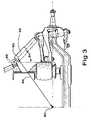
- FIG. 1is a sectional, perspective view of a construction embodying the present invention
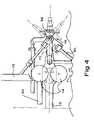
- FIG. 2is a side view of a portion of the invention depicted in FIG. 1 ;
- FIG. 3is a side view of a portion of the invention depicted in FIG. 1 ;
- FIG. 4is a top view of yet another construction embodying the present invention.
- FIG. 5is a side view of the construction depicted in FIG. 4 ;
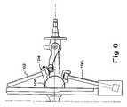
- FIG. 6is a side view of yet another construction embodying the present invention.
- FIG. 1 of the present inventiondepicts two substantially parallel chassis frame rails 10 .
- the chassis frame rails 10may be such as, for example, from a Peterbilt® 377 chassis made by Peterbilt Motors Company of Denton, Tex., although those skilled in the art will understand that other chassis frame rails 10 may be used without departing from the scope or spirit of the invention.
- a steer axle beam 12is preferably located beneath the chassis frame rails 10 .
- the steer axle beam 12is a front steer axle beam 12 such as for example a Dana® Spicer® Steer Axle from the E-1200 W series made by Dana Corporation of Toledo, Ohio, however, the present invention can be used with any axle system.
- the steer axle beam 12is connected to the chassis frame rails 10 through devices and methods known by those skilled in the art.
- One such connecting deviceis at least one air spring 14 .
- the air spring 14may be such as a Firestone ITI4F-4 air spring made by Bridgestone Americas Holding, Inc. of Nashville, Tenn., however, other air springs may also be used.
- the front steer axle beam 12has a first end portion 16 and a second end portion 18 . Both the first 16 and the second end portions 18 are located outboard from the chassis frame rails 10 .
- End portion 16has a first cylindrical portion 20 integrally formed therewith.
- End portion 18has a second cylindrical portion 22 integrally formed therewith.
- a first knuckle 24 and a second knuckle 26are each rotatably mounted to the first and second cylindrical portions 20 and 22 , respectively, of the front steer axle beam 12 .
- the first knuckle 24is mounted by locating a first king pin 28 through both the knuckle 24 and the first cylindrical portion 20 of the front steer axle beam 12 .
- a second king pin 30similarly mounts the second knuckle 26 to the second cylindrical portion 22 of the front steer axle beam 12 .
- the knuckles 24 , 26may be such as for example a Dana® Spicer® steer knuckle from the E-1200 W series made by Dana Corporation of Toledo, Ohio, however, the present invention can be used with any knuckle.
- an upper king pin bracket 38is located adjacent an upper portion 40 of the knuckle 24 .
- a top portion 42 of the king pin 28extends upwardly from the knuckle 24 through an aperture 44 in the bracket 38 .
- the top portion 42 of the king pin 28preferably has a threaded surface 46 for receiving a complimentary threaded nut 48 .
- the nut 48is located on the king pin 28 and tightened thus connecting the bracket 38 to the king pin 28 .
- the upper king pin bracket 38has an attachment portion 50 for a dampening structure 52 and an attachment portion 54 for a rear suspension linkage 56 .
- a lower king pin bracket 58is located adjacent a lower portion 60 of the knuckle 24 in a manner similar to that described for the upper king pin bracket 38 .
- the lower king pin bracket 58preferably has an attachment portion 62 for a front suspension linkage 64 and an attachment portion 66 for a steering tie rod 68 .
- a knuckle steer arm 70is preferably located below the upper king pin bracket 38 and above the steer axle beam 12 . Additionally, the knuckle 24 extends in an outboard direction and has a knuckle spindle 72 for receiving a vehicle wheel (not shown), as known by those skilled in the art.
- At least one dampening structure 52is attached to the chassis frame rail 10 and the dampening structure attachment portion 50 of the upper king pin bracket 38 .
- An inboard end 74 of the dampening structure 52is preferably pivotally mounted to the chassis frame rail 10 with at least one bracket 76 .
- an outboard end 78 of the dampening structure 52is preferably pivotally mounted to the dampening structure attachment portion 50 of the upper king pin bracket 38 .
- Both the inboard 74 and outboard 78 ends of the dampening structure 52are attached to their respective attachment points by any structure which allows the two to pivotally move with respect to one another, such as a pin 80 .
- the dampening structure 52may be any device that mechanically connects the chassis and an end portion, 16 or 18 , and that dampens a compressive and/or de-compressive force between the chassis and an end portion 16 or 18 .
- the dampening structure 52is a shock absorber as known to those skilled in the art.
- the shock absorbermay be for example, a Monroe Shock absorber manufactured by Tenneco Automotive Company of Monroe, Mich.
- any type of shock absorbermay be used depending upon the desired ride and desired vehicle dynamic roll rate.
- any viscoelastic member and/or any mechanical membersuch as, without limitation, air shocks/bags and/or struts and/or shocks and/or springs, can be used as the dampening structure.
- the dampening structure 52is angled so that a longitudinal centerline 82 of the dampening structure 52 is at an acute angle 84 (i.e., less than ninety degrees) from the vertical 86 , as depicted in FIG. 3 .
- the vertical 86is perpendicular to the plane of the supporting surface on which the present invention resides. The exact angle is dependent upon the desired response of the dampening structure 52 to both vertical and roll movements and the stiffness of the dampening structure 52 selected.
- a relatively low anglesuch as between zero and approximately twenty degrees, will result in high roll dampening, but reduced vertical dampening.
- dampening structure 52be at an approximate angle of twenty to sixty degrees to have desirable vertical and roll dampening characteristics, although other angles are well within the scope of the present invention.
- the selected anglemaximizes the perpendicular distance 88 from the centerline 82 of the dampening structure 52 to a vehicle suspension roll center point 90 .
- the vehicle suspension roll center point 90is the point about which the vehicle chassis rotates in response to a roll input.
- the suspension roll center point 90is alternately defined as the point in the transverse axle plane at which lateral forces may be applied to the chassis without producing suspension roll. Maximizing this distance reduces the vehicle dynamic roll and provides shock absorption in the vertical direction. It is also well within the scope of the present invention to connect the dampening structure 52 to the chassis rail 10 and the portion of the axle beam 12 without concern for maximizing the distance to provide a degree of vehicle dynamic roll reduction and shock absorption.
- a dampening structure 52having what is characterized by those skilled in the art as a high dampening coefficient is used.
- the acute installation angle 84 of the dampening structure 52reduces the effectiveness of the dampening structure 52 in vertical motion, however, the installation angle allows the dampening structure 52 to be effective in roll.
- Other dampening structures 52such as for example, air springs can be used to supplement the effectiveness of the suspension in the vertical direction.
- each of the above described componentscan be seen in addition to a torsion tube 92 .
- the torsion tube 92resists, or prevents, twisting of the steer axle beam 12 during roll.
- a bracket 94having an aperture 96 for the torsion tube 92 , is attached to a steer axle beam spring pad 98 .
- the bracket 94may be located anywhere on the steer axle beam 12 .
- the bracket 94is located under an air spring 14 .
- the aperture 96accommodates the torsion tube 92 which extends from one end of the steer axle beam 12 to the other end of the steer axle beam 12 where it is received by a substantially identical bracket (not shown).
- a suspensionsubstantially identical to that disclosed above is depicted.
- the front suspension linkage 100 and the rear suspension linkage 102are attached to a suspension bracket 104 .
- the suspension bracket 104is of a one-piece construction, however, the bracket 104 may be of a multi-piece construction without departing from the scope of the invention.
- the suspension bracket 104connects both linkages 100 , 102 to the steer axle beam 12 and forms the lower seat 106 for an air spring 14 .
- the suspension bracket 104is attached directly to the steer axle beam 12 .
Landscapes
- Engineering & Computer Science (AREA)
- Mechanical Engineering (AREA)
- Chemical & Material Sciences (AREA)
- Combustion & Propulsion (AREA)
- Transportation (AREA)
- Vehicle Body Suspensions (AREA)
Abstract
Description
Claims (17)
Priority Applications (3)
| Application Number | Priority Date | Filing Date | Title |
|---|---|---|---|
| US10/614,232US6997468B2 (en) | 2003-07-07 | 2003-07-07 | Control rod suspension with outboard shock |
| MXPA04006583AMXPA04006583A (en) | 2003-07-07 | 2004-07-05 | Control rod suspension with outboard shock. |
| CA002473104ACA2473104A1 (en) | 2003-07-07 | 2004-07-07 | Control rod suspension with outboard shock |
Applications Claiming Priority (1)
| Application Number | Priority Date | Filing Date | Title |
|---|---|---|---|
| US10/614,232US6997468B2 (en) | 2003-07-07 | 2003-07-07 | Control rod suspension with outboard shock |
Publications (2)
| Publication Number | Publication Date |
|---|---|
| US20050006868A1 US20050006868A1 (en) | 2005-01-13 |
| US6997468B2true US6997468B2 (en) | 2006-02-14 |
Family
ID=33564342
Family Applications (1)
| Application Number | Title | Priority Date | Filing Date |
|---|---|---|---|
| US10/614,232Expired - Fee RelatedUS6997468B2 (en) | 2003-07-07 | 2003-07-07 | Control rod suspension with outboard shock |
Country Status (3)
| Country | Link |
|---|---|
| US (1) | US6997468B2 (en) |
| CA (1) | CA2473104A1 (en) |
| MX (1) | MXPA04006583A (en) |
Cited By (6)
| Publication number | Priority date | Publication date | Assignee | Title |
|---|---|---|---|---|
| US20050110235A1 (en)* | 2003-10-03 | 2005-05-26 | Leblanc James C.Sr. | Wheel suspension system for vehicles |
| US20050218621A1 (en)* | 2004-03-31 | 2005-10-06 | Ziech James F | Beam axle suspension with diagonal link |
| US20050275183A1 (en)* | 2004-02-13 | 2005-12-15 | Hidetoshi Amano | Vehicular rear suspension system |
| US20080084042A1 (en)* | 2006-10-06 | 2008-04-10 | Suresh Gingade Dinakaran | King pin suspension mount adapter |
| US20140210174A1 (en)* | 2013-01-28 | 2014-07-31 | Saf-Holland, Inc. | Auxiliary Axle and Suspension Assembly |
| US8919793B1 (en) | 2010-05-17 | 2014-12-30 | Cush Corporation | Lateral-stability promoting semi-trailer suspension |
Families Citing this family (10)
| Publication number | Priority date | Publication date | Assignee | Title |
|---|---|---|---|---|
| JP4142543B2 (en)* | 2003-09-30 | 2008-09-03 | 本田技研工業株式会社 | Anti-roll bar device mounting structure for vehicle |
| USD555548S1 (en)* | 2005-05-05 | 2007-11-20 | National Association For Stock Car Auto Racing, Inc. | Vehicle frame rail |
| WO2011047275A1 (en)* | 2009-10-15 | 2011-04-21 | World's Fresh Waters Pte. Ltd | Method and system for processing glacial water |
| US8746719B2 (en) | 2010-08-03 | 2014-06-10 | Polaris Industries Inc. | Side-by-side vehicle |
| US9981519B2 (en) | 2015-01-29 | 2018-05-29 | Bombardier Recreational Products Inc. | Rear suspension assembly for an off-road vehicle |
| DE102015211529A1 (en) | 2015-06-23 | 2016-12-29 | Zf Friedrichshafen Ag | independent suspension |
| US10967694B2 (en) | 2017-12-21 | 2021-04-06 | Polaris Industries Inc. | Rear suspension assembly for a vehicle |
| US11260773B2 (en) | 2018-01-09 | 2022-03-01 | Polaris Industries Inc. | Vehicle seating arrangements |
| CN112622550B (en)* | 2020-12-25 | 2022-08-12 | 奇瑞汽车股份有限公司 | Guide structure, vehicle suspension and vehicle |
| US11459035B1 (en)* | 2021-03-16 | 2022-10-04 | Ford Global Technologies, Llc | Shock absorber assembly structures |
Citations (17)
| Publication number | Priority date | Publication date | Assignee | Title |
|---|---|---|---|---|
| US1866167A (en)* | 1929-07-22 | 1932-07-05 | William H Lolley | Shock absorber |
| US2304291A (en) | 1940-01-06 | 1942-12-08 | Nash Kelvinator Corp | Wheel suspension |
| US2403145A (en)* | 1941-07-17 | 1946-07-02 | Budd Edward G Mfg Co | Wheel and motor suspension, especially for automobiles |
| US2756067A (en)* | 1952-10-21 | 1956-07-24 | Porsche Kg | Independent wheel suspensions for power driven vehicles |
| US2941817A (en) | 1955-03-21 | 1960-06-21 | Spencer Safford Loadcraft Inc | Adjustable vehicle axle and air suspension assembly |
| US3512802A (en)* | 1968-03-07 | 1970-05-19 | Arthur La Rock Jr | Tractor rig |
| US4181323A (en)* | 1976-10-01 | 1980-01-01 | Raidel John E | Air spring and parallelogram suspension |
| US4262929A (en) | 1978-12-22 | 1981-04-21 | Lear Siegler, Inc. | Suspension with resilient reaction bar |
| US4662467A (en) | 1984-12-18 | 1987-05-05 | Honda Giken Kogyo Kabushiki Kaisha | Front wheel suspension for a motor vehicle with riding saddle |
| US4802690A (en) | 1986-11-12 | 1989-02-07 | Raidel John E | Suspension assembly for steer axle with single air spring mounted directly over the axle |
| US4951962A (en)* | 1986-07-08 | 1990-08-28 | Toyoda Gosei Co., Ltd. | Vibration-proof structure for axle beam of motor vehicle |
| JPH10181322A (en)* | 1996-12-20 | 1998-07-07 | Fuji Heavy Ind Ltd | Vehicular front suspention device |
| US6073946A (en) | 1997-07-16 | 2000-06-13 | Neway Anchorlok International, Inc. | Trailing arm suspension |
| US6135470A (en) | 1998-06-01 | 2000-10-24 | The Boler Company | Transverse stabilizer for wheel axle suspension system |
| US6293570B1 (en) | 2000-06-15 | 2001-09-25 | The Boler Company. | Self-steering, caster-adjustable suspension system |
| US6375203B1 (en)* | 1999-08-09 | 2002-04-23 | International Truck And Engine Corp. | Front air spring suspension with leading arm trailing and V-link |
| US6866277B2 (en)* | 2002-06-20 | 2005-03-15 | Dana Corporation | Front suspension |
- 2003
- 2003-07-07USUS10/614,232patent/US6997468B2/ennot_activeExpired - Fee Related
- 2004
- 2004-07-05MXMXPA04006583Apatent/MXPA04006583A/enunknown
- 2004-07-07CACA002473104Apatent/CA2473104A1/ennot_activeAbandoned
Patent Citations (17)
| Publication number | Priority date | Publication date | Assignee | Title |
|---|---|---|---|---|
| US1866167A (en)* | 1929-07-22 | 1932-07-05 | William H Lolley | Shock absorber |
| US2304291A (en) | 1940-01-06 | 1942-12-08 | Nash Kelvinator Corp | Wheel suspension |
| US2403145A (en)* | 1941-07-17 | 1946-07-02 | Budd Edward G Mfg Co | Wheel and motor suspension, especially for automobiles |
| US2756067A (en)* | 1952-10-21 | 1956-07-24 | Porsche Kg | Independent wheel suspensions for power driven vehicles |
| US2941817A (en) | 1955-03-21 | 1960-06-21 | Spencer Safford Loadcraft Inc | Adjustable vehicle axle and air suspension assembly |
| US3512802A (en)* | 1968-03-07 | 1970-05-19 | Arthur La Rock Jr | Tractor rig |
| US4181323A (en)* | 1976-10-01 | 1980-01-01 | Raidel John E | Air spring and parallelogram suspension |
| US4262929A (en) | 1978-12-22 | 1981-04-21 | Lear Siegler, Inc. | Suspension with resilient reaction bar |
| US4662467A (en) | 1984-12-18 | 1987-05-05 | Honda Giken Kogyo Kabushiki Kaisha | Front wheel suspension for a motor vehicle with riding saddle |
| US4951962A (en)* | 1986-07-08 | 1990-08-28 | Toyoda Gosei Co., Ltd. | Vibration-proof structure for axle beam of motor vehicle |
| US4802690A (en) | 1986-11-12 | 1989-02-07 | Raidel John E | Suspension assembly for steer axle with single air spring mounted directly over the axle |
| JPH10181322A (en)* | 1996-12-20 | 1998-07-07 | Fuji Heavy Ind Ltd | Vehicular front suspention device |
| US6073946A (en) | 1997-07-16 | 2000-06-13 | Neway Anchorlok International, Inc. | Trailing arm suspension |
| US6135470A (en) | 1998-06-01 | 2000-10-24 | The Boler Company | Transverse stabilizer for wheel axle suspension system |
| US6375203B1 (en)* | 1999-08-09 | 2002-04-23 | International Truck And Engine Corp. | Front air spring suspension with leading arm trailing and V-link |
| US6293570B1 (en) | 2000-06-15 | 2001-09-25 | The Boler Company. | Self-steering, caster-adjustable suspension system |
| US6866277B2 (en)* | 2002-06-20 | 2005-03-15 | Dana Corporation | Front suspension |
Non-Patent Citations (4)
| Title |
|---|
| Hendrickson, Airtek Integrated Front Air Suspension and Steer Axle Technology, 2002. |
| Holen, Peter et al., Aspects on Roll and Bounce Damping for Heavy Vehicles, Nov. 18-20, 2002, Warrendale, PA. |
| Man, All Part of the Whole, Munich, Germany. |
| Neway, AS-Series R.V./Bus Air Steer Suspension, 1997, Muskegon, Michigan. |
Cited By (12)
| Publication number | Priority date | Publication date | Assignee | Title |
|---|---|---|---|---|
| US20050110235A1 (en)* | 2003-10-03 | 2005-05-26 | Leblanc James C.Sr. | Wheel suspension system for vehicles |
| US7798506B2 (en)* | 2003-10-03 | 2010-09-21 | Gpv, L.L.C. | Wheel suspension system for vehicles |
| US20050275183A1 (en)* | 2004-02-13 | 2005-12-15 | Hidetoshi Amano | Vehicular rear suspension system |
| US7258355B2 (en)* | 2004-02-13 | 2007-08-21 | Honda Motor Co., Ltd. | Vehicular rear suspension system |
| US20050218621A1 (en)* | 2004-03-31 | 2005-10-06 | Ziech James F | Beam axle suspension with diagonal link |
| US7188850B2 (en) | 2004-03-31 | 2007-03-13 | Dana Corporation | Beam axle suspension with diagonal link |
| US20080084042A1 (en)* | 2006-10-06 | 2008-04-10 | Suresh Gingade Dinakaran | King pin suspension mount adapter |
| US7614629B2 (en)* | 2006-10-06 | 2009-11-10 | Arvinmeritor Technology, Llc | King pin suspension mount adapter |
| US8919793B1 (en) | 2010-05-17 | 2014-12-30 | Cush Corporation | Lateral-stability promoting semi-trailer suspension |
| US9505284B1 (en) | 2010-05-17 | 2016-11-29 | Cush Corporation | Lateral-stability promoting semi-trailer suspension |
| US20140210174A1 (en)* | 2013-01-28 | 2014-07-31 | Saf-Holland, Inc. | Auxiliary Axle and Suspension Assembly |
| US8967639B2 (en)* | 2013-01-28 | 2015-03-03 | Saf-Holland, Inc. | Auxiliary axle and suspension assembly |
Also Published As
| Publication number | Publication date |
|---|---|
| CA2473104A1 (en) | 2005-01-07 |
| US20050006868A1 (en) | 2005-01-13 |
| MXPA04006583A (en) | 2005-06-08 |
Similar Documents
| Publication | Publication Date | Title |
|---|---|---|
| CA1196658A (en) | Rear wheel suspension with a transverse leaf spring | |
| US9174505B2 (en) | Vehicle independent suspension | |
| US6997468B2 (en) | Control rod suspension with outboard shock | |
| US6782731B2 (en) | System for analyzing a suspension system | |
| EP1789268B1 (en) | Wheel suspension | |
| US7077407B2 (en) | Interconnected suspension | |
| US4458913A (en) | Independent rear wheel suspension | |
| EP1910108B1 (en) | Individual wheel suspension | |
| US20060001311A1 (en) | Front steer axle air suspension system | |
| KR100264649B1 (en) | McPherson Independent Suspension System for Automobile | |
| JP2005506922A (en) | Method and apparatus for suspending a vehicle wheel assembly | |
| EP0083184B1 (en) | Independent rear wheel suspension | |
| KR200237453Y1 (en) | Wishbone type steering system of automobile | |
| KR20080054815A (en) | Strut suspension of vehicle | |
| KR100498697B1 (en) | Torsion beam type suspension | |
| KR100498696B1 (en) | Torsion beam type suspension | |
| KR20070035874A (en) | McPherson strut suspension for wheel camber control | |
| KR100211575B1 (en) | Pin bolt fixing structure of upper arm for a vehicle | |
| KR100199753B1 (en) | Stabilizer bar mounting link structure | |
| KR100831495B1 (en) | Structure of stabilizer bar for automobile | |
| WO2001079009A1 (en) | Wheel axle assembly | |
| KR20040048643A (en) | torsion beam type suspension | |
| KR20160076763A (en) | Suspension with stabilizer for Multi-purpose Utility vehicle and Multi-purpose Utility vehicle containing the same | |
| KR19980028799A (en) | Spring system of semi trailing arm suspension | |
| KR19980029888U (en) | Pin bolt fixing structure of car upper arm shaft pin by leaf spring |
Legal Events
| Date | Code | Title | Description |
|---|---|---|---|
| AS | Assignment | Owner name:DANA CORPORATION, OHIO Free format text:ASSIGNMENT OF ASSIGNORS INTEREST;ASSIGNORS:ZIECH, JAMES F.;POLLOCK, PAUL;REEL/FRAME:014269/0115;SIGNING DATES FROM 20030701 TO 20030703 | |
| FEPP | Fee payment procedure | Free format text:PAYOR NUMBER ASSIGNED (ORIGINAL EVENT CODE: ASPN); ENTITY STATUS OF PATENT OWNER: LARGE ENTITY | |
| AS | Assignment | Owner name:DANA HEAVY VEHICLE SYSTEMS GROUP, LLC, OHIO Free format text:ASSIGNMENT OF ASSIGNORS INTEREST;ASSIGNOR:DANA CORPORATION;REEL/FRAME:020571/0741 Effective date:20080131 Owner name:DANA HEAVY VEHICLE SYSTEMS GROUP, LLC,OHIO Free format text:ASSIGNMENT OF ASSIGNORS INTEREST;ASSIGNOR:DANA CORPORATION;REEL/FRAME:020571/0741 Effective date:20080131 | |
| AS | Assignment | Owner name:CITICORP USA, INC., NEW YORK Free format text:INTELLECTUAL PROPERTY TERM FACILITY SECURITY AGREEMENT;ASSIGNORS:DANA HOLDING CORPORATION;DANA LIMITED;DANA AUTOMOTIVE SYSTEMS GROUP, LLC;AND OTHERS;REEL/FRAME:020859/0359 Effective date:20080131 Owner name:CITICORP USA, INC., NEW YORK Free format text:INTELLECTUAL PROPERTY REVOLVING FACILITY SECURITY AGREEMENT;ASSIGNORS:DANA HOLDING CORPORATION;DANA LIMITED;DANA AUTOMOTIVE SYSTEMS GROUP, LLC;AND OTHERS;REEL/FRAME:020859/0249 Effective date:20080131 Owner name:CITICORP USA, INC.,NEW YORK Free format text:INTELLECTUAL PROPERTY REVOLVING FACILITY SECURITY AGREEMENT;ASSIGNORS:DANA HOLDING CORPORATION;DANA LIMITED;DANA AUTOMOTIVE SYSTEMS GROUP, LLC;AND OTHERS;REEL/FRAME:020859/0249 Effective date:20080131 Owner name:CITICORP USA, INC.,NEW YORK Free format text:INTELLECTUAL PROPERTY TERM FACILITY SECURITY AGREEMENT;ASSIGNORS:DANA HOLDING CORPORATION;DANA LIMITED;DANA AUTOMOTIVE SYSTEMS GROUP, LLC;AND OTHERS;REEL/FRAME:020859/0359 Effective date:20080131 | |
| FPAY | Fee payment | Year of fee payment:4 | |
| REMI | Maintenance fee reminder mailed | ||
| LAPS | Lapse for failure to pay maintenance fees | ||
| STCH | Information on status: patent discontinuation | Free format text:PATENT EXPIRED DUE TO NONPAYMENT OF MAINTENANCE FEES UNDER 37 CFR 1.362 | |
| FP | Lapsed due to failure to pay maintenance fee | Effective date:20140214 |