US6996904B1 - Method for managing cables - Google Patents
Method for managing cablesDownload PDFInfo
- Publication number
- US6996904B1 US6996904B1US08/987,005US98700597AUS6996904B1US 6996904 B1US6996904 B1US 6996904B1US 98700597 AUS98700597 AUS 98700597AUS 6996904 B1US6996904 B1US 6996904B1
- Authority
- US
- United States
- Prior art keywords
- cable
- notch
- edge
- tray
- cables
- Prior art date
- Legal status (The legal status is an assumption and is not a legal conclusion. Google has not performed a legal analysis and makes no representation as to the accuracy of the status listed.)
- Expired - Fee Related
Links
- 238000000034methodMethods0.000titleclaimsabstractdescription19
- 230000008901benefitEffects0.000description4
- 238000010276constructionMethods0.000description3
- 238000013461designMethods0.000description3
- 230000008878couplingEffects0.000description2
- 238000010168coupling processMethods0.000description2
- 238000005859coupling reactionMethods0.000description2
- 238000011161developmentMethods0.000description2
- 230000007246mechanismEffects0.000description2
- 238000012986modificationMethods0.000description2
- 230000004048modificationEffects0.000description2
- 239000013307optical fiberSubstances0.000description2
- 230000008520organizationEffects0.000description2
- 101000910458Mus musculus CDK5 and ABL1 enzyme substrate 1Proteins0.000description1
- 238000005452bendingMethods0.000description1
- 230000005540biological transmissionEffects0.000description1
- 230000000295complement effectEffects0.000description1
- 238000012423maintenanceMethods0.000description1
- 230000006855networkingEffects0.000description1
- 230000002093peripheral effectEffects0.000description1
Images


Classifications
- H—ELECTRICITY
- H02—GENERATION; CONVERSION OR DISTRIBUTION OF ELECTRIC POWER
- H02G—INSTALLATION OF ELECTRIC CABLES OR LINES, OR OF COMBINED OPTICAL AND ELECTRIC CABLES OR LINES
- H02G3/00—Installations of electric cables or lines or protective tubing therefor in or on buildings, equivalent structures or vehicles
- H02G3/02—Details
- H02G3/04—Protective tubing or conduits, e.g. cable ladders or cable troughs
- H02G3/0437—Channels
- H02G3/045—Channels provided with perforations or slots permitting introduction or exit of wires
- H—ELECTRICITY
- H01—ELECTRIC ELEMENTS
- H01R—ELECTRICALLY-CONDUCTIVE CONNECTIONS; STRUCTURAL ASSOCIATIONS OF A PLURALITY OF MUTUALLY-INSULATED ELECTRICAL CONNECTING ELEMENTS; COUPLING DEVICES; CURRENT COLLECTORS
- H01R25/00—Coupling parts adapted for simultaneous co-operation with two or more identical counterparts, e.g. for distributing energy to two or more circuits
- H01R25/16—Rails or bus-bars provided with a plurality of discrete connecting locations for counterparts
- H—ELECTRICITY
- H01—ELECTRIC ELEMENTS
- H01R—ELECTRICALLY-CONDUCTIVE CONNECTIONS; STRUCTURAL ASSOCIATIONS OF A PLURALITY OF MUTUALLY-INSULATED ELECTRICAL CONNECTING ELEMENTS; COUPLING DEVICES; CURRENT COLLECTORS
- H01R9/00—Structural associations of a plurality of mutually-insulated electrical connecting elements, e.g. terminal strips or terminal blocks; Terminals or binding posts mounted upon a base or in a case; Bases therefor
- H01R9/22—Bases, e.g. strip, block, panel
- H01R9/24—Terminal blocks
- H01R9/2416—Means for guiding or retaining wires or cables connected to terminal blocks
- H—ELECTRICITY
- H01—ELECTRIC ELEMENTS
- H01R—ELECTRICALLY-CONDUCTIVE CONNECTIONS; STRUCTURAL ASSOCIATIONS OF A PLURALITY OF MUTUALLY-INSULATED ELECTRICAL CONNECTING ELEMENTS; COUPLING DEVICES; CURRENT COLLECTORS
- H01R24/00—Two-part coupling devices, or either of their cooperating parts, characterised by their overall structure
- H01R24/60—Contacts spaced along planar side wall transverse to longitudinal axis of engagement
- H01R24/62—Sliding engagements with one side only, e.g. modular jack coupling devices
- Y—GENERAL TAGGING OF NEW TECHNOLOGICAL DEVELOPMENTS; GENERAL TAGGING OF CROSS-SECTIONAL TECHNOLOGIES SPANNING OVER SEVERAL SECTIONS OF THE IPC; TECHNICAL SUBJECTS COVERED BY FORMER USPC CROSS-REFERENCE ART COLLECTIONS [XRACs] AND DIGESTS
- Y10—TECHNICAL SUBJECTS COVERED BY FORMER USPC
- Y10T—TECHNICAL SUBJECTS COVERED BY FORMER US CLASSIFICATION
- Y10T29/00—Metal working
- Y10T29/49—Method of mechanical manufacture
- Y10T29/49002—Electrical device making
- Y10T29/49117—Conductor or circuit manufacturing
- Y10T29/49174—Assembling terminal to elongated conductor
- Y—GENERAL TAGGING OF NEW TECHNOLOGICAL DEVELOPMENTS; GENERAL TAGGING OF CROSS-SECTIONAL TECHNOLOGIES SPANNING OVER SEVERAL SECTIONS OF THE IPC; TECHNICAL SUBJECTS COVERED BY FORMER USPC CROSS-REFERENCE ART COLLECTIONS [XRACs] AND DIGESTS
- Y10—TECHNICAL SUBJECTS COVERED BY FORMER USPC
- Y10T—TECHNICAL SUBJECTS COVERED BY FORMER US CLASSIFICATION
- Y10T29/00—Metal working
- Y10T29/49—Method of mechanical manufacture
- Y10T29/49002—Electrical device making
- Y10T29/49117—Conductor or circuit manufacturing
- Y10T29/49194—Assembling elongated conductors, e.g., splicing, etc.
- Y—GENERAL TAGGING OF NEW TECHNOLOGICAL DEVELOPMENTS; GENERAL TAGGING OF CROSS-SECTIONAL TECHNOLOGIES SPANNING OVER SEVERAL SECTIONS OF THE IPC; TECHNICAL SUBJECTS COVERED BY FORMER USPC CROSS-REFERENCE ART COLLECTIONS [XRACs] AND DIGESTS
- Y10—TECHNICAL SUBJECTS COVERED BY FORMER USPC
- Y10T—TECHNICAL SUBJECTS COVERED BY FORMER US CLASSIFICATION
- Y10T29/00—Metal working
- Y10T29/51—Plural diverse manufacturing apparatus including means for metal shaping or assembling
- Y10T29/5187—Wire working
- Y—GENERAL TAGGING OF NEW TECHNOLOGICAL DEVELOPMENTS; GENERAL TAGGING OF CROSS-SECTIONAL TECHNOLOGIES SPANNING OVER SEVERAL SECTIONS OF THE IPC; TECHNICAL SUBJECTS COVERED BY FORMER USPC CROSS-REFERENCE ART COLLECTIONS [XRACs] AND DIGESTS
- Y10—TECHNICAL SUBJECTS COVERED BY FORMER USPC
- Y10T—TECHNICAL SUBJECTS COVERED BY FORMER US CLASSIFICATION
- Y10T29/00—Metal working
- Y10T29/53—Means to assemble or disassemble
- Y10T29/5313—Means to assemble electrical device
- Y10T29/532—Conductor
- Y10T29/53243—Multiple, independent conductors
Definitions
- the inventionrelates in general to the field of cable and conduit management and, more particularly, to the organization and distribution of computer cables or other similar items.
- Computer systemsfor example, personal computers, servers, etc. may be coupled to peripheral and other devices for communicating information such as data, commands, addresses, etc. through a multitude of cables. Oftentimes these cables lay about in a haphazard or dangerous fashion. Cables strewn about a room in disarray offer ample opportunities for tripping over, for damaging the equipment to which they are connected, or for harming other equipment in close proximity. Moreover, cables laying in disarray may make it more difficult and time consuming to find a particular cable or circuit for equipment maintenance periods or during system downtimes. To avoid these problems, most of the current solutions to cable management and organization employ rings or trays of rectangular cross-section that hold the cables in place. These designs work well in some situations, but in some cases they are less than adequate, such as when it is desirable to substantially hide the cables or when space is limited.
- a rectangular cross-section tray designmay not fit snugly into an area (e.g., a corner) where cables will run, or may require too much space down the length of one side of an area to be sufficiently usable.
- the inventionin one embodiment, is a method for using a device capable of carrying a cable, the device having a cover with a port.
- the methodincludes: (1) arranging the cable in the tray; (2) determining that the port is to be used to connect the cable; and (3) connecting the cable to the port.
- FIG. 1is a perspective view representation of a device in accordance with a first embodiment of the invention.
- FIG. 2is an end view of the embodiment in FIG. 1 along line 2 — 2 therein.
- FIG. 3is a sectional exterior view representation of portions of the device in FIG. 1 along line 3 — 3 or line 3 ′— 3 ′ in FIG. 1 in accordance with an embodiment of the invention.
- FIG. 4is another end view illustrating a cable exiting the device in accordance with the embodiment of FIG. 1 .
- FIG. 5is another sectional exterior view representation similar to FIG. 3 with the cable exiting the device as in FIG. 4 .
- FIG. 6is a perspective view of a device similar to the device in FIG. 1 in accordance with a second embodiment of the invention.
- FIG. 7is an end view representation similar to the view along line 7 — 7 in FIG. 6 in accordance with the second embodiment of the invention.
- FIG. 8is a flow chart representation of a method in accordance with an embodiment of the invention.
- FIG. 1shows a perspective representation view
- FIG. 2shows an end view along line 2 — 2 in FIG. 1 of a cable management device 10 in accordance with a first embodiment of the invention.
- the cable management device 10has a somewhat triangular cross-section.
- the cable management device 10includes a tray portion 11 having a rear surface or segment 12 angularly disposed relative to a bottom surface or segment 14 which, in this particular embodiment, are continuous with each other at approximately a right angle. Angles other than a right angle may be employed in alternative embodiments.
- the cable management system 10also includes a removable cover 16 which may be affixed at snapable or bendable edges 17 a and 17 b to both upper 13 and lateral 15 edges of the tray 11 which are located distally from the surfaces 12 and 14 , respectfully.
- the edges 17 a and 17 b of the cover 16are curved and snap or fit over a portion of the upper 13 and lower 15 ends of the tray 11 over the full length of the elongated tray 111 in the embodiment illustrated.
- the cover 16need not cover the full length of the tray 11 provided that the uncovered portion is relatively insubstantial relative to the covered portion.
- FIG. 3which shows a sectional exterior view of either the rear surface 12 or the bottom surface 14
- surface 12is continuous with section 18 and section 18 is continuous with section 19 .
- surface 14is continuous with section 20 and section 20 is continuous with section 21 .
- Sections 18 and 19are angularly disposed with respect to each other at approximately a right angle in this particular embodiment.
- Sections 20 and 21are similarly angularly disposed with respect to each other.
- Sections 18 and 20are also angularly disposed with surfaces 12 and 14 , respectively, forming approximately a right angle in this particular embodiment.
- the notches (or openings) 22 and 23are defined between tabs (or teeth) 24 and 25 , which are continuous with and form part of the notched sections 19 and 21 , respectively.
- the notches 22 , 23 and the tabs 24 , 25may be of sufficient size in the sections 19 and 21 to allow one or more cables to be routed into or out of the tray 11 through the notches 22 and 23 in an organized fashion as will be described below.
- the tabs 24 and 25 of the sections 19 and 21are of sufficient strength to support cables 26 when they are passed through the notches 22 and 23 .
- cables 26which may be a plurality of cables, are arranged or distributed along the length of the tray 11 , and the removable cover 16 is shown in its closed position on the tray 11 over the ends 13 and 15 .
- the cover 16when attached to the tray 11 , will hide the cables 26 except where the cables 26 exit or enter through the notches 22 or 23 (not directly shown in FIG. 4 ).
- only one set, or neither set, of notches 22 or 23is included in the device 10 (i.e., one section, either 19 or 21 may have no openings and the other section does) as set forth below.
- the cable management device 10may be made of plastic, for example, electrically insulating plastic.
- the combined height of the surface 12 and the section 19 , and the combined width of the surface 14 and the section 21may each be approximately two to three inches, although it is possible that other dimensions could be used.
- the length of the tray 11may be from approximately a few inches to approximately several feet long. As will be appreciated by those in the art having the benefit of this disclosure, the actual dimensions of the device 10 will depend on the particular embodiment being implemented.
- the surfaces 12 and 14are continuous by virtue of their construction, they may be separate pieces fixedly joined by any suitable technique.
- the surfaces 12 and 14are continuous by their integral construction whether they be of one piece or two.
- edges 17 a or 17 b of the cover 16may instead be affixed to either one of the ends 13 or 15 of the sections 19 and 21 , respectively, by a suitable hinged mechanism while the unhinged other edge may be snapped over the end 13 or 15 not having the hinged mechanism affixed.
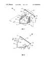
- the device 10may be positioned in a corner 30 between a floor 32 and a wall 34 of a room (not shown).
- the ideal angle between the floor 32 and the wall 34will typically be square or 90 degrees.
- the angle between the surfaces 12 and 14will generally be preferred to also be square.
- the angle between the floor 32 and the wall 34will seldom be ideal, and the angle between the surfaces 12 and 14 need not exactly conform to the angle between the floor 32 and the wall 34 .
- the angle between the surfaces 12 and 14therefore need only substantially approximate the angle between the floor 32 and the wall 34 .
- the cables 26 within the tray 11 of FIG. 4may be, for example, a bundle of ten to twenty network cables (e.g., CAT-5 networking cables) or could be smaller cables, such as computer monitor, keyboard, or mouse cables, optical fiber, etc.
- FIG. 4also shows one of the cables 26 exiting through one of the notches 22 in the section 19 .
- FIG. 5shows a sectional exterior view similar to FIG. 3 with one of the cables 26 exiting through one of the notches 22 or 23 in the sections 19 or 21 , respectively.
- the openings 22 and 23 in the sections 19 and 21 of the cable tray 11allow any of the cables 26 to be routed in and out of the tray 11 .
- More than one of the cables 26could come out of any one of the notches 22 or 23 , depending on the size of the notches 22 or 23 , the size of the cables 26 , the requirements set by or for a particular implementation, or according to the wishes of a user.
- the tray 11could easily fit horizontally along the length of the corner 30 formed between the floor 32 and the wall 34 of the room or vertically along the length of the corner between two walls, or between a ceiling and the wall, of the room.
- the rear surface 12could be mounted to the wall 34 and the fixed bottom surface 14 could be mounted to the floor 32 of the room with screws (not shown) in the surfaces 12 and 14 .
- Pre-tapped screw holescould be provided or screw hole locations could be indicated in the surfaces 12 and 14 (not shown).
- the device 10could be available in various lengths to fit a given wall length or height in a room, or be connected in lengths with triangular junction boxes (not shown) in between pairs of lengths.
- the device 10could be designed to allow a clean junction at room corners, for example, with corner junction boxes (not shown) for coupling the cables 26 to another device 10 , another cable 26 termination point, or for the cable 26 to be routed outside the device 10 for coupling elsewhere.
- the device 10could be designed with an angle, for example, a right angle, in the tray 11 and cover 16 such that the angle would fit in the corner of the room and the device 10 would itself function as a junction box. In this case, the angle would be about a vertical axis parallel to the surface 12 .
- a device 10 ′in accordance with a second embodiment of the invention, shown in a perspective view in FIG. 6 , includes a tray 11 ′ and a cover 16 ′ having ports or connectors 27 (e.g., network ports).
- the tray 11 ′may be similar to tray 11 in the device 10 with the notches 21 and 22 in sections 19 and 21 , or one or both sets of the notches 19 and 21 may be omitted (not shown).
- the device 10 ′is otherwise similar to the device 10 .
- the ports 27 in the cover 16 ′may be, for example, RJ-45 network ports, RJ-11 ports, GPIB ports, serial or parallel ports, DB-9 or DB-25 connectors, or 34 or 50 pin, or other connectors for connecting network cables external to the device 10 ′ to the cables 26 (which may be network cables) which are carried within the device 10 ′, as shown in FIG. 7 in an end view (with the cover 16 ′ closed).
- one of the cables 26is shown coupled by a connector 28 to the port 27 and an external cable 29 is also coupled by a connector 29 a to the port 27 so that signals may be passed between the cables 26 and 29 .
- Such an implementationfacilitates cable connection with the cables 26 to completely contain them within the device 10 ′.
- triangular cable devices 10 or 10 ′could be to hide network or other cables 26 that are run along the corners between wall and floor or ceiling, or to hide the cables 26 running up and down corners between walls.
- Another use of the devices 10 or 10 ′could be to mount it under the working surface of a desk. This would allow the user of a workstation or computer to route monitor, keyboard, mouse, network, or other cables 26 through the trays 11 or 11 ′ and drop them to the workstation or computer, or to a network port.
- the devices 10 or 10 ′could help clear up a tangle of cables beneath the desk.
- the devices 10 or 10 ′could also be used anywhere where a port-like device would need to be routed on a semi-permanent or permanent basis.
- the triangular cable trays 11 or 11 ′may be mounted as in block 102 against a wall, floor, desk, other piece of furniture, etc. (e.g., with screws).
- the cables 26may then be placed and arranged as in block 104 into the trays 11 or 11 ′, as needed, for a particular implementation. If the openings 22 or 23 in the sections 19 or 21 of the cable trays 11 or 11 ′, respectively, are to be used as in block 106 to pass cables, the cables 26 may be routed as in block 108 into or out of the trays 11 or 11 ′, as needed, for further connection.
- the notches 22 or 23could be available in different trays 11 or 11 ′ and could be chosen for a particular implementation based on what type of cable (or cord or hose) 26 is to be routed into or out of the trays 11 or 11 ′.
- the covers 16 or 16 ′may be closed as in block 114 on the trays 11 or 11 ′.
- the ports 27 of the device 10 ′are to be used in the implementation (with or without the notches 22 or 23 being present) to connect, as in block 110 , the cable 26 (or more than one cable 26 ), the cable 26 may be connected, as in block 112 , to the port 27 (e.g., using the appropriate cable 26 connector 28 which is complementary to the port 27 ).
- the cable 26may be connected to or through the port 27 and to the cable 29 external to the cover 16 ′ for further connection to equipment external to the device 10 ′, or for termination.
- the type of port 27could vary depending on what type of cable 26 (or cord or hose), or connection is necessary, sufficient, or preferable for the particular implementation. Moreover, some ports 26 may be interchangeable, and if the device 10 ′ includes the notches 22 or 23 , these may also be used, in similarity to implementations using device 10 as described above. Once all cables 26 are positioned, routed, or connected, or if the ports 27 (device 10 ′) are not used to connect the cables 26 , or if the ports 27 are not included (e.g., device 10 ), the covers 16 or 16 ′ may be positioned as in block 112 , as discussed, on the trays 11 or 11 ′ to close the devices 10 or 10 ′. This may be accomplished by snapping or bending the edges 17 a and 17 b of the covers 16 or 16 ′ over the ends 13 and 15 , respectively, of the sections 19 and 21 as discussed.
- the somewhat triangular cross-section of, for example, the device 10 ′may allow port numbers, which may be indicated near the ports 27 , to be easily read for identification by a standing person. This is possible because the cover 16 ′, when the tray 11 ′ is closed, is aligned at an angle (e.g., a 45 degree angle to vertical).
- the somewhat triangular cross-section of the device 10 ′may also make it less likely that items (e.g., garbage, dirt, etc.) would fall into the ports 27 .
- a small shield(not shown) could be included which prevents these items from falling into the ports.
Landscapes
- Engineering & Computer Science (AREA)
- Architecture (AREA)
- Civil Engineering (AREA)
- Structural Engineering (AREA)
- Insertion, Bundling And Securing Of Wires For Electric Apparatuses (AREA)
Abstract
Description
This patent application is related to U.S. Pat. No. 6,012,683, entitled “Apparatus for Managing Cables,” granted on Jan. 11, 2000.
1. Field of the Invention
The invention relates in general to the field of cable and conduit management and, more particularly, to the organization and distribution of computer cables or other similar items.
2. Description of Related Art
Computer systems, for example, personal computers, servers, etc., may be coupled to peripheral and other devices for communicating information such as data, commands, addresses, etc. through a multitude of cables. Oftentimes these cables lay about in a haphazard or dangerous fashion. Cables strewn about a room in disarray offer ample opportunities for tripping over, for damaging the equipment to which they are connected, or for harming other equipment in close proximity. Moreover, cables laying in disarray may make it more difficult and time consuming to find a particular cable or circuit for equipment maintenance periods or during system downtimes. To avoid these problems, most of the current solutions to cable management and organization employ rings or trays of rectangular cross-section that hold the cables in place. These designs work well in some situations, but in some cases they are less than adequate, such as when it is desirable to substantially hide the cables or when space is limited.
Many times cables in offices are simply dropped down corners of walls and “zip-tied” together. A rectangular cross-section tray design may not fit snugly into an area (e.g., a corner) where cables will run, or may require too much space down the length of one side of an area to be sufficiently usable.
Another use of rectangular cable trays is to hide cables between areas where network drop boxes provide RJ-45 or other types of ports to plug in network cables. With rectangular boxes, the ports are either on the side of the tray where it is sometimes difficult to identify port numbers, or on top of the tray where it is easier for garbage to fall into the ports.
Thus, there exists a need for a cable management system which will avoid or reduce these problems, fit well into a confined space, be unobtrusive, and also provide for easy positioning of cables into and out from the system at particular required locations.
The invention, in one embodiment, is a method for using a device capable of carrying a cable, the device having a cover with a port. The method includes: (1) arranging the cable in the tray; (2) determining that the port is to be used to connect the cable; and (3) connecting the cable to the port.
Other objects and advantages of the invention will become apparent upon reading the following detailed description and upon reference to the drawings in which:
While the invention is susceptible to various modifications and alternative forms, specific embodiments thereof have been shown by way of example in the drawings and are herein described in detail. It should be understood, however, that the description of specific embodiments is not intended to limit the invention to the particular forms disclosed, but on the contrary, the intention is to cover all modifications, equivalents, and alternatives falling within the spirit and scope of the invention as defined by the appended claims.
Illustrative embodiments of the invention are described below. In the interest of clarity, not all features of an actual implementation are described in this specification. It will of course be appreciated that in the development of any such actual embodiment, numerous implementation-specific decisions must be made to achieve the developers' specific goals, such as compliance with system-related and business-related constraints, which will vary from one implementation to another. Moreover, it will be appreciated that such a development effort, even if complex and time-consuming, would nevertheless be a routine undertaking for those of ordinary skill in the art having the benefit of this disclosure.
Thecable management system 10 also includes aremovable cover 16 which may be affixed at snapable orbendable edges tray 11 which are located distally from thesurfaces edges cover 16 are curved and snap or fit over a portion of the upper13 and lower15 ends of thetray 11 over the full length of the elongated tray111 in the embodiment illustrated. In alternative embodiments, thecover 16 need not cover the full length of thetray 11 provided that the uncovered portion is relatively insubstantial relative to the covered portion.
Referring also toFIG. 3 , which shows a sectional exterior view of either therear surface 12 or thebottom surface 14,surface 12 is continuous withsection 18 andsection 18 is continuous withsection 19. Likewise,surface 14 is continuous withsection 20 andsection 20 is continuous withsection 21.Sections Sections Sections surfaces
As shown inFIGS. 1–3 , the notches (or openings)22 and23 are defined between tabs (or teeth)24 and25, which are continuous with and form part of thenotched sections notches tabs sections tray 11 through thenotches tabs sections cables 26 when they are passed through thenotches
Referring now toFIG. 4 ,cables 26, which may be a plurality of cables, are arranged or distributed along the length of thetray 11, and theremovable cover 16 is shown in its closed position on thetray 11 over theends cover 16, when attached to thetray 11, will hide thecables 26 except where thecables 26 exit or enter through thenotches 22 or23 (not directly shown inFIG. 4 ). In certain embodiments, only one set, or neither set, ofnotches
Thecable management device 10 may be made of plastic, for example, electrically insulating plastic. The combined height of thesurface 12 and thesection 19, and the combined width of thesurface 14 and thesection 21, may each be approximately two to three inches, although it is possible that other dimensions could be used. Moreover, the length of thetray 11 may be from approximately a few inches to approximately several feet long. As will be appreciated by those in the art having the benefit of this disclosure, the actual dimensions of thedevice 10 will depend on the particular embodiment being implemented. Further, although thesurfaces surfaces edges cover 16 may instead be affixed to either one of theends sections end
Referring toFIG. 4 , thedevice 10 may be positioned in acorner 30 between afloor 32 and awall 34 of a room (not shown). The ideal angle between thefloor 32 and thewall 34 will typically be square or 90 degrees. Hence, the angle between thesurfaces floor 32 and thewall 34 will seldom be ideal, and the angle between thesurfaces floor 32 and thewall 34. The angle between thesurfaces floor 32 and thewall 34.
Thecables 26 within thetray 11 ofFIG. 4 may be, for example, a bundle of ten to twenty network cables (e.g., CAT-5 networking cables) or could be smaller cables, such as computer monitor, keyboard, or mouse cables, optical fiber, etc.FIG. 4 also shows one of thecables 26 exiting through one of thenotches 22 in thesection 19.FIG. 5 shows a sectional exterior view similar toFIG. 3 with one of thecables 26 exiting through one of thenotches sections openings sections cable tray 11 allow any of thecables 26 to be routed in and out of thetray 11. More than one of thecables 26 could come out of any one of thenotches notches cables 26, the requirements set by or for a particular implementation, or according to the wishes of a user.
In use, thetray 11 could easily fit horizontally along the length of thecorner 30 formed between thefloor 32 and thewall 34 of the room or vertically along the length of the corner between two walls, or between a ceiling and the wall, of the room. For example, therear surface 12 could be mounted to thewall 34 and the fixedbottom surface 14 could be mounted to thefloor 32 of the room with screws (not shown) in thesurfaces surfaces 12 and14 (not shown).
Thedevice 10 could be available in various lengths to fit a given wall length or height in a room, or be connected in lengths with triangular junction boxes (not shown) in between pairs of lengths. Thedevice 10 could be designed to allow a clean junction at room corners, for example, with corner junction boxes (not shown) for coupling thecables 26 to anotherdevice 10, anothercable 26 termination point, or for thecable 26 to be routed outside thedevice 10 for coupling elsewhere. Moreover, in certain embodiments, thedevice 10 could be designed with an angle, for example, a right angle, in thetray 11 and cover16 such that the angle would fit in the corner of the room and thedevice 10 would itself function as a junction box. In this case, the angle would be about a vertical axis parallel to thesurface 12.
In accordance with a second embodiment of the invention, shown in a perspective view inFIG. 6 , adevice 10′ includes atray 11′ and acover 16′ having ports or connectors27 (e.g., network ports). Thetray 11′ may be similar totray 11 in thedevice 10 with thenotches sections notches device 10′ is otherwise similar to thedevice 10. Theports 27 in thecover 16′ may be, for example, RJ-45 network ports, RJ-11 ports, GPIB ports, serial or parallel ports, DB-9 or DB-25 connectors, or 34 or 50 pin, or other connectors for connecting network cables external to thedevice 10′ to the cables26 (which may be network cables) which are carried within thedevice 10′, as shown inFIG. 7 in an end view (with thecover 16′ closed).
InFIG. 7 , one of thecables 26 is shown coupled by aconnector 28 to theport 27 and anexternal cable 29 is also coupled by aconnector 29ato theport 27 so that signals may be passed between thecables FIG. 7 , facilitates cable connection with thecables 26 to completely contain them within thedevice 10′.
One use of thetriangular cable devices other cables 26 that are run along the corners between wall and floor or ceiling, or to hide thecables 26 running up and down corners between walls. Another use of thedevices other cables 26 through thetrays devices devices
Referring toFIG. 8 , a flowchart representation of a method in accordance with an embodiment of the invention is shown. In use, thetriangular cable trays block 102 against a wall, floor, desk, other piece of furniture, etc. (e.g., with screws). Thecables 26 may then be placed and arranged as inblock 104 into thetrays openings sections cable trays block 106 to pass cables, thecables 26 may be routed as inblock 108 into or out of thetrays notches different trays trays cables 26 have been routed into or out of thetrays trays covers block 114 on thetrays
Alternatively, if theports 27 of thedevice 10′ are to be used in the implementation (with or without thenotches block 110, the cable26 (or more than one cable26), thecable 26 may be connected, as inblock 112, to the port27 (e.g., using theappropriate cable 26connector 28 which is complementary to the port27). Hence, thecable 26 may be connected to or through theport 27 and to thecable 29 external to thecover 16′ for further connection to equipment external to thedevice 10′, or for termination.
The type ofport 27 could vary depending on what type of cable26 (or cord or hose), or connection is necessary, sufficient, or preferable for the particular implementation. Moreover, someports 26 may be interchangeable, and if thedevice 10′ includes thenotches implementations using device 10 as described above. Once allcables 26 are positioned, routed, or connected, or if the ports27 (device 10′) are not used to connect thecables 26, or if theports 27 are not included (e.g., device10), thecovers block 112, as discussed, on thetrays devices edges covers ends sections
In certain embodiments, the somewhat triangular cross-section of, for example, thedevice 10′ may allow port numbers, which may be indicated near theports 27, to be easily read for identification by a standing person. This is possible because thecover 16′, when thetray 11′ is closed, is aligned at an angle (e.g., a 45 degree angle to vertical). The somewhat triangular cross-section of thedevice 10′ may also make it less likely that items (e.g., garbage, dirt, etc.) would fall into theports 27. A small shield (not shown) could be included which prevents these items from falling into the ports.
The particular embodiments disclosed above are illustrative only, as the invention may be modified and practiced in different but equivalent manners apparent to those skilled in the art having the benefit of the teachings herein. For instance, the invention may be used to manage many forms of flexible, nonflexible, or partially flexible elongated transmission media such as coaxial cable, twisted wire pairs, optical fibers, etc., or combinations of all the above. Furthermore, no limitations are intended to the details of construction or design herein shown, other than as described in the claims below. It is therefore evident that the particular embodiments disclosed above may be altered or modified and all such variations are considered within the scope and spirit of the invention. Accordingly, the protection sought herein is as set forth in the claims below.
Claims (11)
1. A method comprising:
mounting a tray, the tray including a longitudinal groove that has a substantially uniform cross-section and is defined between first and second longitudinally-extending edges of the tray, the first edge comprising first a notch and the second edge comprising a second notch;
placing a cable in the groove;
selectively routing the cable through the first notch;
selectively routing the cable through the second notch, the cable extending through the first notch in a first direction that is substantially orthogonal to a second direction along which the cable extends through the second notch; and
placing a cover that extends between the first edge and the second edge to close the groove and conceal the cable in the groove.
2. The method ofclaim 1 , wherein placing comprises contacting at least one of the first and second longitudinal edges with the cover.
3. The method ofclaim 1 , wherein the notch in the first edge comprises one out of a plurality of notches in the first longitudinal edge.
4. The method ofclaim 3 , wherein the notch in the second edge comprises one out of a plurality of notches in the second longitudinal edge.
5. The method ofclaim 1 , wherein said plurality of notches are uniformly spaced with respect to each other along the first longitudinal edge.
6. The method ofclaim 1 , wherein the first and second longitudinal edges impart a slope to the cover relative to the edges when the cover closes the groove.
7. A method comprising:
forming a tray, the tray including a longitudinal groove that has a substantially uniform cross-section and is defined between first and second longitudinally-extending edges of the tray, the first edge comprising a first notch and the second edge comprising a second notch;
adapting the tray to hold at least one cable so that the first edge includes the first notch and the second edge includes the second notch so that when the cable is routed through the first notch, the cable extends through the first notch in a first direction and when the cable is routed through the second notch, the cable extends through the second notch in a second direction substantially orthogonal to the first direction; and
forming a cover to extend between the first edge and the second edge to close the groove and conceal the cable in the groove.
8. The method ofclaim 7 , wherein the forming comprises adapting the cover to contact at least one of the first and second longitudinal edges.
9. The method ofclaim 7 , wherein the notch in the first edge comprises one out of a plurality of notches in the first longitudinal edge.
10. The method ofclaim 9 , wherein the notch in the second edge comprises one out of a plurality of notches in the second longitudinal edge.
11. The method ofclaim 9 , wherein said plurality of notches are uniformly spaced with respect to each other along the first longitudinal edge.
Priority Applications (1)
| Application Number | Priority Date | Filing Date | Title |
|---|---|---|---|
| US08/987,005US6996904B1 (en) | 1997-12-08 | 1997-12-08 | Method for managing cables |
Applications Claiming Priority (1)
| Application Number | Priority Date | Filing Date | Title |
|---|---|---|---|
| US08/987,005US6996904B1 (en) | 1997-12-08 | 1997-12-08 | Method for managing cables |
Publications (1)
| Publication Number | Publication Date |
|---|---|
| US6996904B1true US6996904B1 (en) | 2006-02-14 |
Family
ID=35767726
Family Applications (1)
| Application Number | Title | Priority Date | Filing Date |
|---|---|---|---|
| US08/987,005Expired - Fee RelatedUS6996904B1 (en) | 1997-12-08 | 1997-12-08 | Method for managing cables |
Country Status (1)
| Country | Link |
|---|---|
| US (1) | US6996904B1 (en) |
Cited By (11)
| Publication number | Priority date | Publication date | Assignee | Title |
|---|---|---|---|---|
| US20060225912A1 (en)* | 2005-04-01 | 2006-10-12 | Adc Telecommunications, Inc. | Cable Management Bar and Patch Panel |
| US20090101762A1 (en)* | 2007-10-23 | 2009-04-23 | Slam Brands, Inc. | Cable management apparatus, system, and furniture structures |
| US20090102341A1 (en)* | 2007-10-23 | 2009-04-23 | Slam Brands, Inc. | Cable management apparatus, system, and furniture structures |
| US20090101404A1 (en)* | 2007-10-23 | 2009-04-23 | Slam Brands, Inc. | Cable management apparatuses and systems |
| US20100105242A1 (en)* | 2006-12-21 | 2010-04-29 | Panasonic Corporation | Cord accommodation member and its manufacturing method |
| US20110309591A1 (en)* | 2010-06-17 | 2011-12-22 | Bretford Manufacturing, Inc. | Computer Cart |
| FR2991517A1 (en)* | 2012-06-04 | 2013-12-06 | Gewiss France Sas | CHUTE FOR CABLES AND ASSEMBLY COMPRISING SUCH A CHUTE |
| US20150033653A1 (en)* | 2013-08-02 | 2015-02-05 | Zlate B. Malinajdovski | Decorative molding with multiple relief insert |
| USD732316S1 (en) | 2013-06-07 | 2015-06-23 | Herman Miller, Inc. | Table |
| US9089209B2 (en) | 2012-06-08 | 2015-07-28 | Herman Miller, Inc. | Pull-out power and data tray, worksurface assembly and methods for the use thereof |
| US11456581B2 (en)* | 2020-08-24 | 2022-09-27 | Daiwa Kasei Industry Co., Ltd. | Routing structure of wire harness |
Citations (62)
| Publication number | Priority date | Publication date | Assignee | Title |
|---|---|---|---|---|
| US334763A (en)* | 1886-01-26 | Building and system for laying electric conductors therein | ||
| US1857378A (en)* | 1928-08-17 | 1932-05-10 | Jr Harvey Hubbell | Baseboard wiring device |
| US2161492A (en) | 1928-08-21 | 1939-06-06 | Wadsworth Electric Mfg Co | Means for bank switch installations |
| US3338599A (en) | 1965-06-30 | 1967-08-29 | Square D Co | Transposition section for lay-in duct |
| US3403220A (en)* | 1965-10-25 | 1968-09-24 | Riedel Anton | Cable guiding channel |
| US3461220A (en)* | 1965-10-27 | 1969-08-12 | Blackwell & Co Ltd F C | Wiring section for an electrical wiring system |
| US3541244A (en) | 1968-01-15 | 1970-11-17 | Hughes Aircraft Co | Tv bandwidth reduction system |
| US3622686A (en)* | 1970-05-12 | 1971-11-23 | Gen Motors Corp | Conduit for housing a plurality of electric wires and associated connectors |
| US3626086A (en) | 1970-04-28 | 1971-12-07 | Computer Ind Inc | Wire-routing system |
| US3701836A (en)* | 1970-06-27 | 1972-10-31 | Ward Bros Sherburn Ltd | Building structures |
| US3705949A (en) | 1970-09-29 | 1972-12-12 | Ecp Mfg Co | Wireway structure |
| US3890459A (en) | 1974-06-17 | 1975-06-17 | Panduit Corp | Wireway system and retaining finger for use therein |
| US4136257A (en) | 1978-03-01 | 1979-01-23 | Taylor Philip W | Wire duct with wire retaining clip |
| US4406379A (en)* | 1982-06-11 | 1983-09-27 | Westinghouse Electric Corp. | Cable manager |
| US4534147A (en)* | 1982-12-09 | 1985-08-13 | Robert H. Donahue | Duct molding and cable mounting clips |
| US4713007A (en) | 1985-10-11 | 1987-12-15 | Alban Eugene P | Aircraft controls simulator |
| US4715010A (en) | 1984-08-14 | 1987-12-22 | Sharp Kabushiki Kaisha | Schedule alarm device |
| US4774697A (en) | 1985-05-31 | 1988-09-27 | Casio Computer Co., Ltd. | Electronic timepiece including a schedule memory device |
| US4872005A (en) | 1988-01-04 | 1989-10-03 | Motorola, Inc. | Paging receiver capable of reminding a user of an important message event |
| US5008491A (en)* | 1987-08-24 | 1991-04-16 | Butler Manufacturing Company | Floor box for access floors |
| US5023404A (en) | 1989-09-13 | 1991-06-11 | Johnson Service Company | Wiring duct |
| US5043721A (en) | 1989-12-18 | 1991-08-27 | Hewlett-Packard Company | Paging accessory for portable information/computing devices |
| US5076584A (en) | 1989-09-15 | 1991-12-31 | Openiano Renato M | Computer game controller with user-selectable actuation |
| US5086195A (en) | 1987-11-06 | 1992-02-04 | Planet Wattohm | Profile with two fittingly engageable parts, in particular a duct having a body and a cover |
| US5118069A (en) | 1990-02-13 | 1992-06-02 | Lanz Oensingen Ag | Suspension and mounting device |
| US5125843A (en) | 1988-05-27 | 1992-06-30 | Konix Products Limited | Control device |
| US5128981A (en) | 1989-05-24 | 1992-07-07 | Hitachi, Ltd. | Radio communication system and a portable wireless terminal |
| US5139261A (en) | 1989-09-15 | 1992-08-18 | Openiano Renato M | Foot-actuated computer game controller serving as a joystick |
| US5148152A (en) | 1991-01-11 | 1992-09-15 | Stueckle Duane H | Foot pedal control mechanism for computers |
| US5177473A (en) | 1991-03-28 | 1993-01-05 | Drysdale Frank R | Foot operated electrical control with potentiometers |
| USD333324S (en) | 1991-11-25 | 1993-02-16 | Std Electronic International Ltd. | Foot pedal for electronic game |
| USD339612S (en) | 1992-08-14 | 1993-09-21 | Thrustmaster, Inc. | Video game foot pedal controller |
| US5274972A (en)* | 1991-03-18 | 1994-01-04 | Hewing Gmbh | Installation duct for utility lines |
| US5317699A (en) | 1991-12-27 | 1994-05-31 | Nec Corporation | Schedule management system with common memory for multiple users |
| US5316244A (en) | 1990-10-01 | 1994-05-31 | Zetena Jr Maurice F | Supporting brackets for cable raceways |
| US5334997A (en) | 1992-12-22 | 1994-08-02 | David Scallon | Foot-operated computer control |
| US5362923A (en)* | 1991-11-27 | 1994-11-08 | Herman Miller, Inc. | System for distributing and managing cabling within a work space |
| US5396267A (en) | 1992-07-09 | 1995-03-07 | Thrustmaster, Inc. | Reconfigurable video game system |
| US5431569A (en) | 1993-08-27 | 1995-07-11 | Simpkins; Terry J. | Computer interactive motion simulator |
| USD362278S (en) | 1994-09-07 | 1995-09-12 | Hayes Charles L | Foot pedal for electronic game |
| US5451714A (en) | 1993-03-11 | 1995-09-19 | Spectranet International | Telephone and data signal distribution system and raceway and panel associated therewith |
| US5497141A (en) | 1994-05-12 | 1996-03-05 | Timecorp Systems, Inc. | Automated labor alert and remote messaging system |
| US5499020A (en) | 1991-08-15 | 1996-03-12 | Nec Corporation | Data display radio pager |
| USD368496S (en) | 1994-04-25 | 1996-04-02 | Seger James W | Foot pedal for use with video games |
| US5528667A (en) | 1992-10-13 | 1996-06-18 | U.S. Philips Corporation | Time management for cordless telephone by inputs from a user through the keypad to cause data to be transferred to the external source via input terminals and mating terminals on a battery charger |
| US5548506A (en) | 1994-03-17 | 1996-08-20 | Srinivasan; Seshan R. | Automated, electronic network based, project management server system, for managing multiple work-groups |
| US5548932A (en) | 1994-11-08 | 1996-08-27 | Maxcess Technologies, Inc. | Adjustable cable tray support system |
| US5552807A (en) | 1994-12-07 | 1996-09-03 | Hayes; Charles L. | Foot pedal assembly for use with personal computer |
| US5597980A (en)* | 1994-11-30 | 1997-01-28 | Yazaki Corporation | Detachable mounting mechanism for a fuel injector wiring harness cover |
| US5616078A (en) | 1993-12-28 | 1997-04-01 | Konami Co., Ltd. | Motion-controlled video entertainment system |
| US5623242A (en) | 1995-04-26 | 1997-04-22 | Anteon Corporation | Prescription reminder system and method |
| JPH09237530A (en)* | 1996-02-28 | 1997-09-09 | Sumitomo Wiring Syst Ltd | Mounting jig for corrugated tube of wire harness |
| US5709249A (en) | 1994-06-27 | 1998-01-20 | Yazaki Corporation | Locking structure |
| US5728976A (en) | 1996-05-22 | 1998-03-17 | Dek, Inc. | Detachable cover for wire ducts having a living hinge |
| US5732747A (en)* | 1997-01-21 | 1998-03-31 | Icm Corporation | Cove molding cover for electrical cables |
| US5831211A (en)* | 1996-04-04 | 1998-11-03 | Clifford W. Gartung | Variable-type cable management and distribution system |
| US5836148A (en) | 1996-02-06 | 1998-11-17 | Kunimorikagaku Ltd. | Cable chain |
| USD404101S (en)* | 1997-01-10 | 1999-01-12 | Bauer Inc. | Brake for an in-line roller skate |
| USD403951S (en)* | 1997-09-16 | 1999-01-12 | International Connectors And Cable Corporation | Rear mounted cable management bar |
| US5877451A (en) | 1997-05-29 | 1999-03-02 | Zimmerman; Harry I. | Flanged conduit and insulation for electric wires and method of use |
| US5902961A (en) | 1997-01-28 | 1999-05-11 | The Siemon Company | Cable manager |
| US6012683A (en)* | 1997-12-08 | 2000-01-11 | Micron Technology, Inc. | Apparatus for managing cables |
- 1997
- 1997-12-08USUS08/987,005patent/US6996904B1/ennot_activeExpired - Fee Related
Patent Citations (62)
| Publication number | Priority date | Publication date | Assignee | Title |
|---|---|---|---|---|
| US334763A (en)* | 1886-01-26 | Building and system for laying electric conductors therein | ||
| US1857378A (en)* | 1928-08-17 | 1932-05-10 | Jr Harvey Hubbell | Baseboard wiring device |
| US2161492A (en) | 1928-08-21 | 1939-06-06 | Wadsworth Electric Mfg Co | Means for bank switch installations |
| US3338599A (en) | 1965-06-30 | 1967-08-29 | Square D Co | Transposition section for lay-in duct |
| US3403220A (en)* | 1965-10-25 | 1968-09-24 | Riedel Anton | Cable guiding channel |
| US3461220A (en)* | 1965-10-27 | 1969-08-12 | Blackwell & Co Ltd F C | Wiring section for an electrical wiring system |
| US3541244A (en) | 1968-01-15 | 1970-11-17 | Hughes Aircraft Co | Tv bandwidth reduction system |
| US3626086A (en) | 1970-04-28 | 1971-12-07 | Computer Ind Inc | Wire-routing system |
| US3622686A (en)* | 1970-05-12 | 1971-11-23 | Gen Motors Corp | Conduit for housing a plurality of electric wires and associated connectors |
| US3701836A (en)* | 1970-06-27 | 1972-10-31 | Ward Bros Sherburn Ltd | Building structures |
| US3705949A (en) | 1970-09-29 | 1972-12-12 | Ecp Mfg Co | Wireway structure |
| US3890459A (en) | 1974-06-17 | 1975-06-17 | Panduit Corp | Wireway system and retaining finger for use therein |
| US4136257A (en) | 1978-03-01 | 1979-01-23 | Taylor Philip W | Wire duct with wire retaining clip |
| US4406379A (en)* | 1982-06-11 | 1983-09-27 | Westinghouse Electric Corp. | Cable manager |
| US4534147A (en)* | 1982-12-09 | 1985-08-13 | Robert H. Donahue | Duct molding and cable mounting clips |
| US4715010A (en) | 1984-08-14 | 1987-12-22 | Sharp Kabushiki Kaisha | Schedule alarm device |
| US4774697A (en) | 1985-05-31 | 1988-09-27 | Casio Computer Co., Ltd. | Electronic timepiece including a schedule memory device |
| US4713007A (en) | 1985-10-11 | 1987-12-15 | Alban Eugene P | Aircraft controls simulator |
| US5008491A (en)* | 1987-08-24 | 1991-04-16 | Butler Manufacturing Company | Floor box for access floors |
| US5086195A (en) | 1987-11-06 | 1992-02-04 | Planet Wattohm | Profile with two fittingly engageable parts, in particular a duct having a body and a cover |
| US4872005A (en) | 1988-01-04 | 1989-10-03 | Motorola, Inc. | Paging receiver capable of reminding a user of an important message event |
| US5125843A (en) | 1988-05-27 | 1992-06-30 | Konix Products Limited | Control device |
| US5128981A (en) | 1989-05-24 | 1992-07-07 | Hitachi, Ltd. | Radio communication system and a portable wireless terminal |
| US5023404A (en) | 1989-09-13 | 1991-06-11 | Johnson Service Company | Wiring duct |
| US5139261A (en) | 1989-09-15 | 1992-08-18 | Openiano Renato M | Foot-actuated computer game controller serving as a joystick |
| US5076584A (en) | 1989-09-15 | 1991-12-31 | Openiano Renato M | Computer game controller with user-selectable actuation |
| US5043721A (en) | 1989-12-18 | 1991-08-27 | Hewlett-Packard Company | Paging accessory for portable information/computing devices |
| US5118069A (en) | 1990-02-13 | 1992-06-02 | Lanz Oensingen Ag | Suspension and mounting device |
| US5316244A (en) | 1990-10-01 | 1994-05-31 | Zetena Jr Maurice F | Supporting brackets for cable raceways |
| US5148152A (en) | 1991-01-11 | 1992-09-15 | Stueckle Duane H | Foot pedal control mechanism for computers |
| US5274972A (en)* | 1991-03-18 | 1994-01-04 | Hewing Gmbh | Installation duct for utility lines |
| US5177473A (en) | 1991-03-28 | 1993-01-05 | Drysdale Frank R | Foot operated electrical control with potentiometers |
| US5499020A (en) | 1991-08-15 | 1996-03-12 | Nec Corporation | Data display radio pager |
| USD333324S (en) | 1991-11-25 | 1993-02-16 | Std Electronic International Ltd. | Foot pedal for electronic game |
| US5362923A (en)* | 1991-11-27 | 1994-11-08 | Herman Miller, Inc. | System for distributing and managing cabling within a work space |
| US5317699A (en) | 1991-12-27 | 1994-05-31 | Nec Corporation | Schedule management system with common memory for multiple users |
| US5396267A (en) | 1992-07-09 | 1995-03-07 | Thrustmaster, Inc. | Reconfigurable video game system |
| USD339612S (en) | 1992-08-14 | 1993-09-21 | Thrustmaster, Inc. | Video game foot pedal controller |
| US5528667A (en) | 1992-10-13 | 1996-06-18 | U.S. Philips Corporation | Time management for cordless telephone by inputs from a user through the keypad to cause data to be transferred to the external source via input terminals and mating terminals on a battery charger |
| US5334997A (en) | 1992-12-22 | 1994-08-02 | David Scallon | Foot-operated computer control |
| US5451714A (en) | 1993-03-11 | 1995-09-19 | Spectranet International | Telephone and data signal distribution system and raceway and panel associated therewith |
| US5431569A (en) | 1993-08-27 | 1995-07-11 | Simpkins; Terry J. | Computer interactive motion simulator |
| US5616078A (en) | 1993-12-28 | 1997-04-01 | Konami Co., Ltd. | Motion-controlled video entertainment system |
| US5548506A (en) | 1994-03-17 | 1996-08-20 | Srinivasan; Seshan R. | Automated, electronic network based, project management server system, for managing multiple work-groups |
| USD368496S (en) | 1994-04-25 | 1996-04-02 | Seger James W | Foot pedal for use with video games |
| US5497141A (en) | 1994-05-12 | 1996-03-05 | Timecorp Systems, Inc. | Automated labor alert and remote messaging system |
| US5709249A (en) | 1994-06-27 | 1998-01-20 | Yazaki Corporation | Locking structure |
| USD362278S (en) | 1994-09-07 | 1995-09-12 | Hayes Charles L | Foot pedal for electronic game |
| US5548932A (en) | 1994-11-08 | 1996-08-27 | Maxcess Technologies, Inc. | Adjustable cable tray support system |
| US5597980A (en)* | 1994-11-30 | 1997-01-28 | Yazaki Corporation | Detachable mounting mechanism for a fuel injector wiring harness cover |
| US5552807A (en) | 1994-12-07 | 1996-09-03 | Hayes; Charles L. | Foot pedal assembly for use with personal computer |
| US5623242A (en) | 1995-04-26 | 1997-04-22 | Anteon Corporation | Prescription reminder system and method |
| US5836148A (en) | 1996-02-06 | 1998-11-17 | Kunimorikagaku Ltd. | Cable chain |
| JPH09237530A (en)* | 1996-02-28 | 1997-09-09 | Sumitomo Wiring Syst Ltd | Mounting jig for corrugated tube of wire harness |
| US5831211A (en)* | 1996-04-04 | 1998-11-03 | Clifford W. Gartung | Variable-type cable management and distribution system |
| US5728976A (en) | 1996-05-22 | 1998-03-17 | Dek, Inc. | Detachable cover for wire ducts having a living hinge |
| USD404101S (en)* | 1997-01-10 | 1999-01-12 | Bauer Inc. | Brake for an in-line roller skate |
| US5732747A (en)* | 1997-01-21 | 1998-03-31 | Icm Corporation | Cove molding cover for electrical cables |
| US5902961A (en) | 1997-01-28 | 1999-05-11 | The Siemon Company | Cable manager |
| US5877451A (en) | 1997-05-29 | 1999-03-02 | Zimmerman; Harry I. | Flanged conduit and insulation for electric wires and method of use |
| USD403951S (en)* | 1997-09-16 | 1999-01-12 | International Connectors And Cable Corporation | Rear mounted cable management bar |
| US6012683A (en)* | 1997-12-08 | 2000-01-11 | Micron Technology, Inc. | Apparatus for managing cables |
Non-Patent Citations (4)
| Title |
|---|
| www.globetray.com-Globetray Cable Tray, G.S. Metals Corp., Pickneyville, IL., Jan. 1997. |
| www.siemon.com/products, Multi Access Horizontal Cable Managers, The Siemon Company, Aug. 7, 1997. |
| www.siemon.com/products/newproducts/nmultiaccesscm.html, Aug. 1997.* |
| www.usacitylink.com/afshome/cable, Baron Desmond, Jun. 1, 1997. |
Cited By (20)
| Publication number | Priority date | Publication date | Assignee | Title |
|---|---|---|---|---|
| US7200931B2 (en)* | 2005-04-01 | 2007-04-10 | Adc Telecommunications, Inc. | Cable management bar and patch panel |
| US20060225912A1 (en)* | 2005-04-01 | 2006-10-12 | Adc Telecommunications, Inc. | Cable Management Bar and Patch Panel |
| US20100105242A1 (en)* | 2006-12-21 | 2010-04-29 | Panasonic Corporation | Cord accommodation member and its manufacturing method |
| US8148638B2 (en)* | 2006-12-21 | 2012-04-03 | Panasonic Corporation | Cord accommodation member for television entertainment shelf and its manufacturing method |
| US20090102341A1 (en)* | 2007-10-23 | 2009-04-23 | Slam Brands, Inc. | Cable management apparatus, system, and furniture structures |
| US20090101404A1 (en)* | 2007-10-23 | 2009-04-23 | Slam Brands, Inc. | Cable management apparatuses and systems |
| US7825337B2 (en) | 2007-10-23 | 2010-11-02 | Slam Brands, Inc. | Cable management apparatuses and systems |
| US7922128B2 (en) | 2007-10-23 | 2011-04-12 | Slam Brands, Inc. | Cable management apparatus, system, and furniture structures |
| US20090101762A1 (en)* | 2007-10-23 | 2009-04-23 | Slam Brands, Inc. | Cable management apparatus, system, and furniture structures |
| US20110309591A1 (en)* | 2010-06-17 | 2011-12-22 | Bretford Manufacturing, Inc. | Computer Cart |
| US20140245605A1 (en)* | 2010-06-17 | 2014-09-04 | Bretford Manufacturing, Inc. | Computer Cart |
| US9398735B2 (en)* | 2010-06-17 | 2016-07-19 | Bretford Manufacturing Inc. | Computer cart |
| US8752848B2 (en)* | 2010-06-17 | 2014-06-17 | Bretford Manufacturing, Inc. | Computer cart |
| FR2991517A1 (en)* | 2012-06-04 | 2013-12-06 | Gewiss France Sas | CHUTE FOR CABLES AND ASSEMBLY COMPRISING SUCH A CHUTE |
| EP2672592A1 (en) | 2012-06-04 | 2013-12-11 | Gewiss France SA | Chute for cable tray and unit including such a chute |
| US9089209B2 (en) | 2012-06-08 | 2015-07-28 | Herman Miller, Inc. | Pull-out power and data tray, worksurface assembly and methods for the use thereof |
| US9474367B2 (en) | 2012-06-08 | 2016-10-25 | Herman Miller, Inc. | Pull-out power and data tray, worksurface assembly and methods for the use thereof |
| USD732316S1 (en) | 2013-06-07 | 2015-06-23 | Herman Miller, Inc. | Table |
| US20150033653A1 (en)* | 2013-08-02 | 2015-02-05 | Zlate B. Malinajdovski | Decorative molding with multiple relief insert |
| US11456581B2 (en)* | 2020-08-24 | 2022-09-27 | Daiwa Kasei Industry Co., Ltd. | Routing structure of wire harness |
Similar Documents
| Publication | Publication Date | Title |
|---|---|---|
| US6012683A (en) | Apparatus for managing cables | |
| US7227082B2 (en) | Multimedia outlet box | |
| US6918796B2 (en) | Vertical cable management system with ribcage structure | |
| CA2195130C (en) | Variable-type cable management and distribution system | |
| US6866541B2 (en) | Angled patch panel with cable support bar for network cable racks | |
| US6785459B2 (en) | Cable management brackets and cabinet | |
| US6884942B2 (en) | Cable manager for network rack | |
| US6410850B1 (en) | Cable enclosure assembly | |
| US5647045A (en) | Multi-media connection housing | |
| US6996904B1 (en) | Method for managing cables | |
| US8106311B2 (en) | Cable pathway patch rack with waterfall member | |
| US7848608B2 (en) | Fiber routing system with drop-in device | |
| RU2558334C2 (en) | Conduit and cabling system with adhesive coating for communication media | |
| US6009223A (en) | Bracket assembly for strain relief of optical fiber jumpers | |
| US20040020232A1 (en) | Underfloor cable junction unit and computer center equipped with such junction units | |
| US20020009278A1 (en) | Optic fiber management module and furniture incorporating same | |
| US20050247478A1 (en) | Cable manager for network rack | |
| MXPA01006997A (en) | Vertical cable management system with ribcage structure | |
| HK1107627A (en) | Vertical cable management system with ribcage structure |
Legal Events
| Date | Code | Title | Description |
|---|---|---|---|
| AS | Assignment | Owner name:MICRON ELECTRONICS, INC., IDAHO Free format text:ASSIGNMENT OF ASSIGNORS INTEREST;ASSIGNOR:HOWELL, MATTHEW G.;REEL/FRAME:009201/0022 Effective date:19980414 | |
| AS | Assignment | Owner name:MEI CALIFORNIA, INC., CALIFORNIA Free format text:ASSIGNMENT OF ASSIGNORS INTEREST;ASSIGNOR:MICRON ELECTRONICS, INC.;REEL/FRAME:011658/0956 Effective date:20010322 | |
| AS | Assignment | Owner name:MICRON TECHNOLOGY, INC., IDAHO Free format text:ASSIGNMENT OF ASSIGNORS INTEREST;ASSIGNOR:MEI CALIFORNIA, INC.;REEL/FRAME:012391/0370 Effective date:20010322 | |
| FEPP | Fee payment procedure | Free format text:PAYOR NUMBER ASSIGNED (ORIGINAL EVENT CODE: ASPN); ENTITY STATUS OF PATENT OWNER: LARGE ENTITY | |
| CC | Certificate of correction | ||
| FPAY | Fee payment | Year of fee payment:4 | |
| REMI | Maintenance fee reminder mailed | ||
| LAPS | Lapse for failure to pay maintenance fees | ||
| STCH | Information on status: patent discontinuation | Free format text:PATENT EXPIRED DUE TO NONPAYMENT OF MAINTENANCE FEES UNDER 37 CFR 1.362 | |
| FP | Lapsed due to failure to pay maintenance fee | Effective date:20140214 |