US6996195B2 - Channel estimation in a communication system - Google Patents
Channel estimation in a communication systemDownload PDFInfo
- Publication number
- US6996195B2 US6996195B2US09/746,376US74637600AUS6996195B2US 6996195 B2US6996195 B2US 6996195B2US 74637600 AUS74637600 AUS 74637600AUS 6996195 B2US6996195 B2US 6996195B2
- Authority
- US
- United States
- Prior art keywords
- channel
- calculating
- estimate
- power profile
- interpolator
- Prior art date
- Legal status (The legal status is an assumption and is not a legal conclusion. Google has not performed a legal analysis and makes no representation as to the accuracy of the status listed.)
- Expired - Lifetime, expires
Links
- 238000004891communicationMethods0.000titleabstractdescription40
- 238000000034methodMethods0.000claimsabstractdescription47
- 239000011159matrix materialSubstances0.000claimsdescription31
- 238000012549trainingMethods0.000claimsdescription21
- 238000004364calculation methodMethods0.000claimsdescription6
- 230000001131transforming effectEffects0.000claims2
- 230000005540biological transmissionEffects0.000description12
- 238000004422calculation algorithmMethods0.000description9
- 239000013598vectorSubstances0.000description7
- 230000004044responseEffects0.000description6
- 238000013459approachMethods0.000description4
- 238000005562fadingMethods0.000description4
- 230000008569processEffects0.000description4
- 239000000969carrierSubstances0.000description3
- 230000000694effectsEffects0.000description3
- 230000003044adaptive effectEffects0.000description2
- 230000008901benefitEffects0.000description2
- 238000005314correlation functionMethods0.000description2
- 238000005516engineering processMethods0.000description2
- 238000004088simulationMethods0.000description2
- 238000004458analytical methodMethods0.000description1
- 238000012937correctionMethods0.000description1
- 238000000354decomposition reactionMethods0.000description1
- 230000003247decreasing effectEffects0.000description1
- 230000006735deficitEffects0.000description1
- 238000010586diagramMethods0.000description1
- 238000005259measurementMethods0.000description1
- 238000012986modificationMethods0.000description1
- 230000004048modificationEffects0.000description1
- 238000012545processingMethods0.000description1
- 238000011084recoveryMethods0.000description1
- 238000001228spectrumMethods0.000description1
Images

Classifications
- H—ELECTRICITY
- H04—ELECTRIC COMMUNICATION TECHNIQUE
- H04L—TRANSMISSION OF DIGITAL INFORMATION, e.g. TELEGRAPHIC COMMUNICATION
- H04L25/00—Baseband systems
- H04L25/02—Details ; arrangements for supplying electrical power along data transmission lines
- H04L25/0202—Channel estimation
- H04L25/0212—Channel estimation of impulse response
- H04L25/0216—Channel estimation of impulse response with estimation of channel length
- H—ELECTRICITY
- H04—ELECTRIC COMMUNICATION TECHNIQUE
- H04L—TRANSMISSION OF DIGITAL INFORMATION, e.g. TELEGRAPHIC COMMUNICATION
- H04L25/00—Baseband systems
- H04L25/02—Details ; arrangements for supplying electrical power along data transmission lines
- H04L25/0202—Channel estimation
- H04L25/022—Channel estimation of frequency response
- H—ELECTRICITY
- H04—ELECTRIC COMMUNICATION TECHNIQUE
- H04L—TRANSMISSION OF DIGITAL INFORMATION, e.g. TELEGRAPHIC COMMUNICATION
- H04L27/00—Modulated-carrier systems
- H04L27/26—Systems using multi-frequency codes
- H04L27/2601—Multicarrier modulation systems
- H04L27/2647—Arrangements specific to the receiver only
Definitions
- the present inventionrelates generally to methods and apparatus for estimating a channel susceptible to distortion in a communication system. More particularly, the present invention relates to an apparatus and an associated method, for estimating channels in orthogonal frequency division multiplexed (OFDM) communication systems.
- OFDMorthogonal frequency division multiplexed
- Digital communication techniqueshave been developed and implemented in communication systems, including communication systems utilizing radio channels. Digital communication techniques generally permit the communication system in which the techniques are implemented to achieve greater transmission capacity as contrasted to the capacity available with conventional analog communication techniques.
- a communication systemgenerally comprises a sending station and a receiving station communicating by way of one or more communication channels. Data to be communicated by the sending station to the receiving station is converted, if necessary, into a form to permit its transmission on the communication channel.
- a communication systemcan be defined by almost any combination of sending and receiving stations, including, for instance, circuit board-positioned sending and receiving elements as well as more conventionally-defined communication systems including users spaced at great distances apart communicating data between each other by transmission over radio channels.
- the receiving stationWhen data transmitted on a communication channel is received at the receiving station, the receiving station acts upon, if necessary, the received data to recreate the informational content of the transmitted data.
- the data received at the receiving stationis identical to the data transmitted by the sending station.
- much of the datamay be distorted during its transmission on the communication channel. Such distortion distorts the data as received at the receiving station. If the distortion is significant, the informational content of portions of the data may not be recoverable.
- a radio communication systemis one example of a communication system utilized to transmit data between sending and receiving stations.
- the communication channelis formed of a radio communication channel.
- a radio communication channelmay be defined within a portion of the electromagnetic spectrum.
- a wireline communication systemin contrast, a physical connection between the sending and receiving stations is implemented to form the communication channel. Transmission of data upon a radio communication channel is particularly susceptible to distortion, due in part to the propagation characteristics of the radio communication channel. Data communicated on conventional wireline channels are also, however, susceptible to distortion in manners analogous to the manner by which distortion is introduced upon the data transmitted in a radio communication system.
- informationwhich is to be communicated, is digitized to form digital bits.
- the digital bitsare typically formatted according to a formatting scheme. Groups of the digital bits, for example, are assembled to form a packet of data.
- Orthogonal Frequency Division Multiplexingis a method that allows transmitting high data rates over extremely degraded channels at a comparable low complexity.
- OFDMOrthogonal Frequency Division Multiplexing
- In the classical terrestrial broadcasting scenarioin contrast to, for example, satellite communications where we have one single direct path from transmitter to receiver, we have to deal with a multipath-channel as the transmitted signal arrives at the receiver along various paths of different length. Since multiple versions of the signal interfere with each other (inter symbol interference (ISI)) it becomes very difficult to extract the original information.
- ISIinter symbol interference
- the common representation of the multipath channelis the channel impulse response (cir) of the channel, which is the signal received at the receiving station if a single pulse is transmitted from the transmitter.
- the critical measure concerning the multipath-channelis the delay Tm of the longest path with respect to the earliest path.
- Tmthe delay of the longest path with respect to the earliest path.
- a received symbolcan theoretically be influenced by Tm/T previous symbols. This influence has to be estimated and compensated for in the receiver, a task that may become very challenging.
- Multi-path transmission of the data upon a radio channel or other communication channelintroduces distortion upon the data as the data is actually communicated to the receiving station by a multiple number of paths.
- the data detected at the receiving stationtherefore, is the combination of signal values of data communicated upon a plurality of communication paths. Intersymbol interference and Rayleigh fading causes distortion of the data. Such distortion, if not compensated for, prevents the accurate recovery of the transmitted data.
- time correlationis used for channel estimate enhancement.
- a time interpolatorrelies on the correlation between different channel taps in the time domain, which requires the knowledge of the channel statistics versus time.
- the techniquerequires calculating the interpolator for every transmission burst.
- the interpolatorrequires a matrix inversion of dimension N (the size of the training sequence) for every burst which increases the system complexity.
- the inventionpresents a method and apparatus for estimating channels in orthogonal frequency division multiplexed (OFDM) communication systems.
- the method and apparatusallows a channel estimate to be determined independent of having knowledge on channel statistics.
- the method and apparatusmay be implemented in OFDM systems having single or multiple transmitting antennas.
- the method and apparatusis implemented in an OFDM system utilizing at least two antennas.
- Channel estimationis performed by determining and then utilizing a least square (LS) estimate and an interpolation coefficient for each transmitting antenna.
- the interpolation coefficientis determined independently from the statistics of the channel, i.e., without needing the channel multipath power profile (CMPP).
- CMPPchannel multipath power profile
- the interpolation coefficientis determined by estimating the maximum delay encountered by the channel, calculating a maximum number of multipaths L by dividing the maximum delay by the transmitted symbol duration, creating a channel multipath power profile for the receiver using L, and performing a fast fourier transform (FFT) on the multipath power profile to generate a frequency correction vector which is used to determine an interpolator coefficient in the form of an interpolator matrix M.
- FFTfast fourier transform
- the method and apparatusprovides a channel estimate, which is very close to the exact channel. Moreover, it can be readily applied to different communication systems such as MIMO (Multi Input Multi Output), SIMO (Single-Input Multi-Output), MISO (Multi-Input Single-Output) and (Single-Input Single-Output).
- MIMOMulti Input Multi Output
- SIMOSingle-Input Multi-Output
- MISOMulti-Input Single-Output
- the method and apparatusdoes not rely on knowledge of the channel statistics (either in time or frequency) to enhance the LS estimate, and does not require such information.
- the interpolatoris implemented mathematically by multiplying the LS estimate by the matrix M.
- the matrix Mis required to be estimated once, hence, the technique does not require estimating M every burst and does not include any mathematical operation except multiplication. Consequently, the approach has a very limited complexity, and therefore, can be easily implemented.
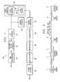
- FIG. 1illustrates portions of a receiver according to an embodiment of the invention
- FIG. 2illustrates portions of a channel estimator according to an embodiment of the invention
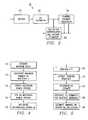
- FIG. 3illustrates process steps performed when applying interpolation according to an embodiment of the invention
- FIG. 4is a flow chart illustrating process steps performed when calculating interpolation coefficients according to an embodiment of the invention.
- FIG. 5is a flow chart illustrating process steps performed when applying interpolation to estimate a channel according to an embodiment of the invention.
- Receiver 100includes time synchronizer 30 , frequency offset corrector 32 , fast fourier transform (FFT) operator 34 , channel estimator 36 , channel corrector 42 , demodulator 44 , deinterleaver 46 , depuncturer 48 , Viterbi decoder 50 , and phase corrector 52 .
- Phase corrector 52includes pilot remover 38 and phase tracker 40 .
- a signal r(t), received over a radio channelis input to time synchronizer 30 .
- Time synchronizer 30synchronizes the signal to the beginning of a transmission burst or block.
- Frequency offset corrector 32then corrects the signal for any offset errors that occur between the transmitter local oscillator and the local oscillator of receiver 100 .
- the corrected signalis then input to FFT operator 34 and converted from the time domain to the frequency domain.
- the frequency domain signalis then input to phase corrector 52 , which comprises pilot remover 35 and phase tracker 40 .
- Phase correctors 52provide an estimate of the phase to channel corrector 42 .
- Channel estimator 36also receives the frequency domain signal and provides an estimate of the gain that the channel has incurred to channel corrector 42 , which provides the corrected signal to demodulator 44 .
- Demodulator 44deinterleaver 46 , depuncturer 48 , and Viterbi decoder 50 , together form the decoder function in receiver 100 .
- Buffer 54receives the frequency domain signal from FFT operator 34 and stores a training sequence from the frequency domain signal.
- a least squares (LS) channel estimateis then determined by performing division on the training sequence in LS estimator 56 .
- Channel estimate decoupler 58then decouples the LS channel estimate for each channel received over a separate antenna if more than one trasmitting antenna is being used, i.e., over each of a plurality of antennas.
- Coefficient interpolator and channel estimator 60receives each decoupled LS channel estimate from decoupler 58 .
- Coefficient interpolator and channel estimatorthen multiplies interpolation coefficient for each channel by the LS estimator to obtain final channel estimates.
- channel estimator 36in the embodiment of FIG. 1 , the case of two transmitting antennas may be used as an example. The embodiment however, may be implemented for any number N of transmitting antennas.
- An OFDM transmitter having two transmitting antennas (Tx 1 , Tx 2 ) transmitting to receiver 100 , with receiver 100 having one receiving antenna (Rx), for a down link transmission (the general case of M transmitting antennas is straightforward)will be used in this example.
- Each transmitting antenna Tx 1 , Tx 2 of the transmittermay use a long training sequence of length N.
- Q Ais assumed to be the diagonal N ⁇ N matrix whose entries are the elements of A
- h 1is assumed to be the N ⁇ 1 channel response for the i th (i ⁇ 1 , 2 ⁇ ) transmitting antenna
- n iis assumed to be the N ⁇ 1 noise vector associated with the i th (i ⁇ 1 , 2 ⁇ ) received training sequence, and has a variance ⁇ 2 .
- LSleast squares
- the LS estimatemay be obtained by dividing the received training sequences with the actual ones. It can be also noted from [4] and [5] that the LS channel estimate is a noisy version of the exact one (i.e. the LS channel estimate is the exact channel response plus noise).
- the channelis estimated by coefficient interpolator and channel estimator 60 using a MMSE based filter to enhance the LS channel estimates represented by [4] and [5].
- Thismitigates the effect of the noise vectors in equation [4] and [5] by decreasing the noise energy (variance).
- Thisis done by combining the LS channel estimates received from channel estimate decoupler 58 with suitable interpolating coefficients that are determined in coefficient interpolator and channel estimator 60 .
- the MMSE interpolator coefficient Mis based on the well-known MMSE criteria.
- R x,yE[xy H ] and x H would be the conjugate transpose of x.
- the filter Mminimizes the average error between the interpolated LS channel estimate ⁇ i and the exact channel response h i . This has the effect of preserving the useful term in equations [4] and [5] (i.e. h i ) while minimizing the noise term (i.e. v l ).
- CMPPchannel statistics manifested in CMPP
- CMPPcomplementary metal-oxide-semiconductor
- the embodiment of the inventionprovides an approach that almost does the same job as the exact MMSE interpolator without depending on the knowledge of CMPP (or equivalent the channel statistics) at the receiver.
- the above algorithmis replaced by an algorithm that may be performed independent of knowledge of the CMPP.
- Lemmamay be used to describe the method and apparatus.
- R Hi.Hiresults from the fact that the channel coefficients are uncorrected for different paths, hence the off-diagonal entries in R Hi.Hi vanish or equivalently, R Hi.Hi is a diagonal matrix.
- the diagonal entriesrepresent the power in each path, i.e. the components of the CMPP.
- Equation [8]indicates that the function of the interpolator is equivalent in the time domain to scaling the k th component of the LS channel estimate for each transmitting antenna with ⁇ (k).
- Nthe number of multipaths in the channel.
- H ithe useful term in equation [12]
- V ithe entries of the noise term V i are all nonzero.
- the maximum number of channel taps L ch that can existis so well defined, i.e. the ratio between the channel multipath spread Tm and the symbol duration T.
- a scenario that achieves most of the interpolator performance with much less complexityis to fix a multipath power profile at the receiver that basically includes a number of taps equal to L ch .
- the RMPPwill never miss a tap that is in CMPP.
- the coefficient interpolator and channel estimator 60will use a RMPP covering all the expected taps in CMPP. The values of the interpolation coefficients can then be determined (based on only knowing L ch ). The coefficient interpolator and channel estimator 60 then would use these coefficients to interpolate the LS channel estimate. It is to be noted again that the same coefficients are to be used every burst, so the coefficient interpolator and channel estimator 60 need not to calculate ⁇ circumflex over (M) ⁇ (and hence find the inverse of N ⁇ N matrix) every burst.
- a received time signal consisting of the training signalis convoluted with the channel plus White Gaussian Noise (WGN) ( 1 ).
- the time signalis then converted to the frequency domain via FFT operation ( 2 ) in FFT operator 34 .
- the LS estimator 56multiplies the received signal in the frequency domain by the conjugate of the training sequence ( 3 ) to result in a noisy version of the channel response.
- Coefficient interpolator and channel estimator 60takes the LS estimate in the time domain ( 4 ).
- the coefficient interpolator and channel estimator 60scales the first L ch components using ones and it replaces the last N-L ch components by zeros ( 5 ). This process has the effect of suppressing a lot ofnoise components while not affecting all the channel components since the channel can only exist at some positions in the first L ch components.
- the new (less-noisy) estimateis then transformed to the frequency domain ( 6 ). Consequently, the interpolator acts as a low-pass filter but in the time domain.
- FIG. 4therein is a flow chart illustrating process steps when calculating the interpolation coefficient according to an embodiment of the invention.
- Tmchannel multipath spread
- an estimate of the maximum delay encountered by the channelis performed. From block ( 10 ) the maximum number of multipaths L can be calculated by dividing the maximum delay encountered by the channel Tm by the symbol duration T ( 12 ). In block ( 14 ), a receiver multipath power profile is created. Next, in block ( 16 ) by performing an FFT operation on the receiver multipath power profile, the frequency correlation vector is found. Next, in block ( 18 ), the interpolator matrix M is calculated by constructing the teoplitz of ⁇ .
- FIG. 5therein is a flow chart illustrating process steps when applying interpolation according to an embodiment of the invention.
- the process described in FIG. 6is a burst by burst process to obtain the least square channel estimate.
- the received signal r(t)is put into the frequency domain by the FFT operation ( 20 ) and the training sequence is extracted from the preamble of the burst ( 22 ).
- a least square channel estimateis obtained by dividing the received training sequence by the exact training sequence ( 24 ).
- Block ( 26 )exists only in the case of multiple antennas case and comprises the step of decoupling the different channels corresponding to the different transmitting antennas.
- a complex matrix-vector multiplicationis performed, by multiplying the least square channel estimates and the interpolating coefficients to estimate each channel.
Landscapes
- Engineering & Computer Science (AREA)
- Computer Networks & Wireless Communication (AREA)
- Signal Processing (AREA)
- Power Engineering (AREA)
- Noise Elimination (AREA)
Abstract
Description
B=A
C=Aejπ/2
D=Ae−jπ/2 [1]
z1=QAh1+jQAh2+n1, [2]
z2=QAh1−jQAh2+n2, [3]
Where v1and v2would be the new noise vectors with
From [4] and [5], the LS estimate may be obtained by dividing the received training sequences with the actual ones. It can be also noted from [4] and [5] that the LS channel estimate is a noisy version of the exact one (i.e. the LS channel estimate is the exact channel response plus noise).
ĥi=M·hi,lsi=1,2 [6]
- Input: hi,ls, i=1,2.
- Output: ĥi, i=1,2.
Algorithm:
For a particular radio channel knowing CMPP, find - R=Toeplitz[FFT(CMPP)].
- Knowing the noise variance, substitute in [7] to get M.
- Substitute in equation [6] to get ĥi, i=1,2.
Proof
hi,ls=hi+vi, i=1,2 [11]
Hi,ls=Hi+Vi, i=1,2 [12]
where Hi=IDFT(hi), i=1,2 and due to the orthogonality of the IDFT operator, the new noise components are also independently identically distributed (iid) but with a
Solving for the MMSE filter F that estimates Hifrom Hi,lsin equation [12], we get,
then the exact value of the multipath profile used at the receiver is irrelevant and what really matters is the positions of these taps. In other words, we can achieve almost the same performance if the receiver used a Receiver Multipath Power Profile (RMPP) that differs from the channel one (CMPP) as long as it does not miss a tap in CMPP (i.e. as long as there is no zero entry in RMFPP which corresponds to a nonzero entry in CMPP).
Claims (14)
Priority Applications (1)
| Application Number | Priority Date | Filing Date | Title |
|---|---|---|---|
| US09/746,376US6996195B2 (en) | 1999-12-22 | 2000-12-21 | Channel estimation in a communication system |
Applications Claiming Priority (2)
| Application Number | Priority Date | Filing Date | Title |
|---|---|---|---|
| US17147099P | 1999-12-22 | 1999-12-22 | |
| US09/746,376US6996195B2 (en) | 1999-12-22 | 2000-12-21 | Channel estimation in a communication system |
Publications (2)
| Publication Number | Publication Date |
|---|---|
| US20010036235A1 US20010036235A1 (en) | 2001-11-01 |
| US6996195B2true US6996195B2 (en) | 2006-02-07 |
Family
ID=26867138
Family Applications (1)
| Application Number | Title | Priority Date | Filing Date |
|---|---|---|---|
| US09/746,376Expired - LifetimeUS6996195B2 (en) | 1999-12-22 | 2000-12-21 | Channel estimation in a communication system |
Country Status (1)
| Country | Link |
|---|---|
| US (1) | US6996195B2 (en) |
Cited By (23)
| Publication number | Priority date | Publication date | Assignee | Title |
|---|---|---|---|---|
| US20020181390A1 (en)* | 2001-04-24 | 2002-12-05 | Mody Apurva N. | Estimating channel parameters in multi-input, multi-output (MIMO) systems |
| US20040131012A1 (en)* | 2002-10-04 | 2004-07-08 | Apurva Mody | Methods and systems for sampling frequency offset detection, correction and control for MIMO OFDM systems |
| US20040208115A1 (en)* | 2003-04-17 | 2004-10-21 | Der-Zheng Liu | Multiple antenna ofdm transceiver and method for transceiving |
| US20050165949A1 (en)* | 2004-01-28 | 2005-07-28 | Teague Edward H. | Method and apparatus of using a single channel to provide acknowledgement and assignment messages |
| US20050170783A1 (en)* | 2002-10-29 | 2005-08-04 | Ranganathan Krishnan | Channel estimation for OFDM communication systems |
| US20060133522A1 (en)* | 2004-12-22 | 2006-06-22 | Arak Sutivong | MC-CDMA multiplexing in an orthogonal uplink |
| US20060153239A1 (en)* | 2004-12-22 | 2006-07-13 | Qualcomm Incorporated | Method of using a share resources in a communication system |
| US20060239370A1 (en)* | 2001-04-24 | 2006-10-26 | Mody Apurva N | Time and frequency synchronization in multi-input, multi-output (MIMO) systems |
| US20060279435A1 (en)* | 2002-10-29 | 2006-12-14 | Ranganathan Krishnan | Uplink pilot and signaling transmission in wireless communication systems |
| US20060286995A1 (en)* | 2005-06-20 | 2006-12-21 | Texas Instruments Incorporated | Slow Uplink Power Control |
| US20070211790A1 (en)* | 2003-05-12 | 2007-09-13 | Qualcomm Incorporated | Fast Frequency Hopping With a Code Division Multiplexed Pilot in an OFDMA System |
| US7277685B2 (en) | 2003-04-17 | 2007-10-02 | Realtek Semiconductor Corp. | Automatic gain control of multiple antenna OFDM receiver |
| WO2008013398A1 (en)* | 2006-07-28 | 2008-01-31 | Samsung Electronics Co., Ltd. | Method and apparatus for positioning pilot in an ofdma mobile communication system |
| US20080069190A1 (en)* | 2006-09-18 | 2008-03-20 | Mediatek Inc. | Receiver of a coma system with a path alignment circuit |
| US20080137603A1 (en)* | 2004-12-22 | 2008-06-12 | Qualcomm Incorporated | Method of implicit deassignment of resources |
| US20080178983A1 (en)* | 2007-01-30 | 2008-07-31 | Christina Louise Braidwood | Composite-forming method, composites formed thereby, and printed circuit boards incorporating them |
| US20080240310A1 (en)* | 2007-04-02 | 2008-10-02 | Industrial Technology Research Institute | Method for estimating and compensating frequency offset and frequency offset estimation module |
| US20080273583A1 (en)* | 2007-05-04 | 2008-11-06 | Kee-Bong Song | Channel estimation for ofdm-based wireless communication system using sparsely spaced pilot subcarriers |
| US20090274252A1 (en)* | 2005-01-28 | 2009-11-05 | At&T Intellectual Propery I, L.P. | Delay Restricted Channel Estimation for Multi-Carrier Systems |
| US7639600B1 (en)* | 2003-02-12 | 2009-12-29 | Marvell International Ltd. | Low complexity channel estimation for orthogonal frequency division modulation systems |
| US8331463B2 (en) | 2005-08-22 | 2012-12-11 | Qualcomm Incorporated | Channel estimation in communications |
| US8890744B1 (en) | 1999-04-07 | 2014-11-18 | James L. Geer | Method and apparatus for the detection of objects using electromagnetic wave attenuation patterns |
| US9480074B2 (en) | 2004-07-23 | 2016-10-25 | Qualcomm Incorporated | Enabling quick and easy demodulation |
Families Citing this family (23)
| Publication number | Priority date | Publication date | Assignee | Title |
|---|---|---|---|---|
| JP2001339328A (en)* | 2000-05-25 | 2001-12-07 | Communication Research Laboratory | Receiver, reception method, and information recording medium |
| US20020065047A1 (en)* | 2000-11-30 | 2002-05-30 | Moose Paul H. | Synchronization, channel estimation and pilot tone tracking system |
| US7154964B1 (en)* | 2001-04-09 | 2006-12-26 | At&T Corp. | Creating training sequences for space-time diversity arrangements |
| US7230911B2 (en)* | 2001-05-10 | 2007-06-12 | Intel Corporation | Sparse channel estimation for orthogonal frequency division multiplexed signals |
| US7088787B2 (en)* | 2001-09-24 | 2006-08-08 | Atheros Communications, Inc. | Post-FFT scaling to reduce multiple effects |
| US7305050B2 (en) | 2002-05-13 | 2007-12-04 | Marvell Dspc Ltd. | Method and apparatus for processing signals received from a channel having a variable channel length |
| US7418049B2 (en)* | 2002-06-03 | 2008-08-26 | Vixs Systems Inc. | Method and apparatus for decoding baseband orthogonal frequency division multiplex signals |
| US7613248B2 (en)* | 2002-06-24 | 2009-11-03 | Qualcomm Incorporated | Signal processing with channel eigenmode decomposition and channel inversion for MIMO systems |
| US7394873B2 (en)* | 2002-12-18 | 2008-07-01 | Intel Corporation | Adaptive channel estimation for orthogonal frequency division multiplexing systems or the like |
| US7006810B1 (en) | 2002-12-19 | 2006-02-28 | At&T Corp. | Method of selecting receive antennas for MIMO systems |
| US7260055B2 (en) | 2003-05-30 | 2007-08-21 | Agency For Science, Technology, And Research | Method for reducing channel estimation error in an OFDM system |
| US20050059366A1 (en)* | 2003-09-16 | 2005-03-17 | Atheros Communications, Inc. | Spur mitigation techniques |
| US7616698B2 (en) | 2003-11-04 | 2009-11-10 | Atheros Communications, Inc. | Multiple-input multiple output system and method |
| WO2005055543A1 (en)* | 2003-12-03 | 2005-06-16 | Australian Telecommunications Cooperative Research Centre | Channel estimation for ofdm systems |
| CN100405790C (en)* | 2004-06-25 | 2008-07-23 | 北京邮电大学 | An Adaptive Channel Estimation Method Based on Two-Dimensional Iterative Least Squares Criterion |
| KR100689418B1 (en)* | 2004-09-24 | 2007-03-08 | 삼성전자주식회사 | Apparatus and method for delay spread estimation of multipath fading channel in wireless communication system |
| KR100941901B1 (en)* | 2005-03-01 | 2010-02-16 | 퀄컴 인코포레이티드 | Channel estimate optimization for multiple transmit modes |
| US20070064740A1 (en)* | 2005-09-19 | 2007-03-22 | Shai Waxman | Device, system and method of clock synchronization |
| SG132516A1 (en)* | 2005-11-10 | 2007-06-28 | Oki Techno Ct Singapore Pte | A system and method for performing ls equalization on a signal in an ofdm system |
| US7991083B2 (en)* | 2006-06-22 | 2011-08-02 | Cisco Technology, Inc. | Method and system for detecting preambles in a multi-cell system |
| US20080181095A1 (en)* | 2007-01-29 | 2008-07-31 | Zangi Kambiz C | Method and Apparatus for Impairment Correlation Estimation in Multi-Antenna Receivers |
| CN101286775A (en)* | 2007-04-12 | 2008-10-15 | 北京三星通信技术研究有限公司 | Multi-antenna spatial multiplexing system using enhanced signal detection |
| US8885456B2 (en)* | 2009-07-10 | 2014-11-11 | Mitsubishi Electric Corporation | Demodulator and frame synchronization method |
Citations (3)
| Publication number | Priority date | Publication date | Assignee | Title |
|---|---|---|---|---|
| US6452981B1 (en)* | 1996-08-29 | 2002-09-17 | Cisco Systems, Inc | Spatio-temporal processing for interference handling |
| US6621808B1 (en)* | 1999-08-13 | 2003-09-16 | International Business Machines Corporation | Adaptive power control based on a rake receiver configuration in wideband CDMA cellular systems (WCDMA) and methods of operation |
| US6654429B1 (en)* | 1998-12-31 | 2003-11-25 | At&T Corp. | Pilot-aided channel estimation for OFDM in wireless systems |
- 2000
- 2000-12-21USUS09/746,376patent/US6996195B2/ennot_activeExpired - Lifetime
Patent Citations (3)
| Publication number | Priority date | Publication date | Assignee | Title |
|---|---|---|---|---|
| US6452981B1 (en)* | 1996-08-29 | 2002-09-17 | Cisco Systems, Inc | Spatio-temporal processing for interference handling |
| US6654429B1 (en)* | 1998-12-31 | 2003-11-25 | At&T Corp. | Pilot-aided channel estimation for OFDM in wireless systems |
| US6621808B1 (en)* | 1999-08-13 | 2003-09-16 | International Business Machines Corporation | Adaptive power control based on a rake receiver configuration in wideband CDMA cellular systems (WCDMA) and methods of operation |
Non-Patent Citations (10)
| Title |
|---|
| Channel estimation for OFDM systems with transmitter diversity in mobile wireless channelsYe Li; Seshadri, N.; Ariyavisitakul, S.; Selected Areas in Communications, IEEE Journal on , vol.: 17 , Issue: 3 , Mar. 1999, pp.: 461-471.* |
| J.J. Vande Beek, O. Edfors, M. Sandelli, S. K. Wilson, and P. O. Borjeson, "OFDM Channel Estimation with Singular Value Decomposition," in proc. 46th IEEE on Vehicular Technology Conference, Atlanta, GA, Apr. 1996, pp. 923-927. |
| J.J. Vande Beek, O. Edfors, M. Sandelli, S. K. Wilson, and P. O. Borjeson, "On Channel Estimation in OFDM systems," in proc. 45th IEEE on Vehicular Technology Conference, IL, Jul. 1995, pp. 815-819. |
| OFDM channel estimation by singular value decomposition;Edfors, O. et al. ; Vehicular Technology Conference, 1996. 'Mobile Technology for Human Race'., IEEE 46th , vol.: 2, Apr. 28-May 1, 1996, pp.: 923-927 vol. 2.* |
| OFDM channel estimation by singular value decomposition;Edfors, O. et al. ; Vehicular Technology Conference, 1996. 'Mobile Technology for the Human Race'., IEEE 46th , vol.: 2 , Apr. 28-May 1, 1996, pp.: 923-927 vol. 2.* |
| Robust channel estimation for OFDM systems with rapid dispersive fading channelsLi, Y.; Cimini, L.J., Jr.; Sollenberger, N.R.; □□Communications, IEEE Transactions on, vol.: 46 , Issue; 7 , Jul. 1998, pp.: 902-915.* |
| Robust channel estimation for OFDM systems with rapid dispersive fading channelsLi, Y.; Cimini, L.J., Jr.; Sollenberger, N.R.; Communications, IEEE Transactions on , vol.: 46 , Issue: 7, Jul. 1998, pp. 902-915.* |
| S. K. Wilson, R. E. Khayata and J. M. Cioffi, "16 QAM Modulation with Orthogonal Frequency Division Multiplexing in a Rayleigh-Fading Environment," in proc. VTC-1994, pp. 1660-1664, Stockholm, Sweden, Jun. 1994. |
| Y. Li, N. Seshadri and S. Ariyavisitakul, "Channel Estimation for OFDM Systems with Transmitter Diversity in Mobile Wireless Channels," IEEE JSAC, vol. 17, No. 3, Mar. 1999. |
| Y. Lli, L. J. Cimini, JRr. and N. R. Sollenberger, "Robust Channel Estimation for OFDM Systems with Rapid Dispersive Fading Channels," IEEE Trans. On Communications, vol. 46, No. 7 , Jul. 1998. |
Cited By (51)
| Publication number | Priority date | Publication date | Assignee | Title |
|---|---|---|---|---|
| US9551785B1 (en) | 1999-04-07 | 2017-01-24 | James L. Geer | Method and apparatus for the detection of objects using electromagnetic wave attenuation patterns |
| US8890744B1 (en) | 1999-04-07 | 2014-11-18 | James L. Geer | Method and apparatus for the detection of objects using electromagnetic wave attenuation patterns |
| US7310304B2 (en)* | 2001-04-24 | 2007-12-18 | Bae Systems Information And Electronic Systems Integration Inc. | Estimating channel parameters in multi-input, multi-output (MIMO) systems |
| US20020181390A1 (en)* | 2001-04-24 | 2002-12-05 | Mody Apurva N. | Estimating channel parameters in multi-input, multi-output (MIMO) systems |
| US7706458B2 (en) | 2001-04-24 | 2010-04-27 | Mody Apurva N | Time and frequency synchronization in Multi-Input, Multi-Output (MIMO) systems |
| US20060239370A1 (en)* | 2001-04-24 | 2006-10-26 | Mody Apurva N | Time and frequency synchronization in multi-input, multi-output (MIMO) systems |
| US7889819B2 (en) | 2002-10-04 | 2011-02-15 | Apurva Mody | Methods and systems for sampling frequency offset detection, correction and control for MIMO OFDM systems |
| US20040131012A1 (en)* | 2002-10-04 | 2004-07-08 | Apurva Mody | Methods and systems for sampling frequency offset detection, correction and control for MIMO OFDM systems |
| US8724555B2 (en) | 2002-10-29 | 2014-05-13 | Qualcomm Incorporated | Uplink pilot and signaling transmission in wireless communication systems |
| US20060279435A1 (en)* | 2002-10-29 | 2006-12-14 | Ranganathan Krishnan | Uplink pilot and signaling transmission in wireless communication systems |
| US7463576B2 (en)* | 2002-10-29 | 2008-12-09 | Qualcomm Incorporated | Channel estimation for OFDM communication systems |
| US20050170783A1 (en)* | 2002-10-29 | 2005-08-04 | Ranganathan Krishnan | Channel estimation for OFDM communication systems |
| US9155106B2 (en) | 2002-10-29 | 2015-10-06 | Qualcomm Incorporated | Uplink pilot and signaling transmission in wireless communication systems |
| US7952990B1 (en) | 2003-02-12 | 2011-05-31 | Marvell International Ltd. | Low complexity channel estimation for orthogonal frequency division modulation systems |
| US7639600B1 (en)* | 2003-02-12 | 2009-12-29 | Marvell International Ltd. | Low complexity channel estimation for orthogonal frequency division modulation systems |
| US7277685B2 (en) | 2003-04-17 | 2007-10-02 | Realtek Semiconductor Corp. | Automatic gain control of multiple antenna OFDM receiver |
| US20040208115A1 (en)* | 2003-04-17 | 2004-10-21 | Der-Zheng Liu | Multiple antenna ofdm transceiver and method for transceiving |
| US7257078B2 (en)* | 2003-04-17 | 2007-08-14 | Realtek Semiconductor Corp. | Multiple antenna OFDM transceiver and method for transceiving |
| US8102832B2 (en) | 2003-05-12 | 2012-01-24 | Qualcomm Incorporated | Fast frequency hopping with a code division multiplexed pilot in an OFDMA system |
| US20070211790A1 (en)* | 2003-05-12 | 2007-09-13 | Qualcomm Incorporated | Fast Frequency Hopping With a Code Division Multiplexed Pilot in an OFDMA System |
| US8611283B2 (en) | 2004-01-28 | 2013-12-17 | Qualcomm Incorporated | Method and apparatus of using a single channel to provide acknowledgement and assignment messages |
| US20050165949A1 (en)* | 2004-01-28 | 2005-07-28 | Teague Edward H. | Method and apparatus of using a single channel to provide acknowledgement and assignment messages |
| US9871617B2 (en) | 2004-07-23 | 2018-01-16 | Qualcomm Incorporated | Method of optimizing portions of a frame |
| US9480074B2 (en) | 2004-07-23 | 2016-10-25 | Qualcomm Incorporated | Enabling quick and easy demodulation |
| US8817897B2 (en) | 2004-12-22 | 2014-08-26 | Qualcomm Incorporated | MC-CDMA multiplexing in an orthogonal uplink |
| US8831115B2 (en) | 2004-12-22 | 2014-09-09 | Qualcomm Incorporated | MC-CDMA multiplexing in an orthogonal uplink |
| US20060153239A1 (en)* | 2004-12-22 | 2006-07-13 | Qualcomm Incorporated | Method of using a share resources in a communication system |
| US8649451B2 (en) | 2004-12-22 | 2014-02-11 | Qualcomm Incorporated | MC-CDMA multiplexing in an orthogonal uplink |
| US8638870B2 (en) | 2004-12-22 | 2014-01-28 | Qualcomm Incorporated | MC-CDMA multiplexing in an orthogonal uplink |
| US20060133522A1 (en)* | 2004-12-22 | 2006-06-22 | Arak Sutivong | MC-CDMA multiplexing in an orthogonal uplink |
| US20110064039A1 (en)* | 2004-12-22 | 2011-03-17 | Qualcomm Incorporated | Mc-cdma multiplexing in an orthogonal uplink |
| US20080137603A1 (en)* | 2004-12-22 | 2008-06-12 | Qualcomm Incorporated | Method of implicit deassignment of resources |
| US8238923B2 (en) | 2004-12-22 | 2012-08-07 | Qualcomm Incorporated | Method of using shared resources in a communication system |
| US20110235685A1 (en)* | 2004-12-22 | 2011-09-29 | Qualcomm Incorporated | Mc-cdma multiplexing in an orthogonal uplink |
| US7986614B2 (en) | 2005-01-28 | 2011-07-26 | At&T Intellectual Property I, L.P. | Delay restricted channel estimation for multi-carrier systems |
| US8649254B2 (en) | 2005-01-28 | 2014-02-11 | At&T Intellectual Property I, L.P. | Delay restricted channel estimation for multi-carrier systems |
| US20090274252A1 (en)* | 2005-01-28 | 2009-11-05 | At&T Intellectual Propery I, L.P. | Delay Restricted Channel Estimation for Multi-Carrier Systems |
| US8305874B2 (en) | 2005-01-28 | 2012-11-06 | At & T Intellectual Property I, L.P. | Delay restricted channel estimation for multi-carrier systems |
| US20060286995A1 (en)* | 2005-06-20 | 2006-12-21 | Texas Instruments Incorporated | Slow Uplink Power Control |
| US7668564B2 (en) | 2005-06-20 | 2010-02-23 | Texas Instruments Incorporated | Slow uplink power control |
| US8331463B2 (en) | 2005-08-22 | 2012-12-11 | Qualcomm Incorporated | Channel estimation in communications |
| US20080068980A1 (en)* | 2006-07-28 | 2008-03-20 | Samsung Electronics Co., Ltd. | Method and apparatus for positioning pilot in an ofdma mobile communication system |
| US7869341B2 (en) | 2006-07-28 | 2011-01-11 | Samsung Electronics Co., Ltd. | Method and apparatus for positioning pilot in an OFDMA mobile communication system |
| WO2008013398A1 (en)* | 2006-07-28 | 2008-01-31 | Samsung Electronics Co., Ltd. | Method and apparatus for positioning pilot in an ofdma mobile communication system |
| US7839917B2 (en)* | 2006-09-18 | 2010-11-23 | Mediatek Inc. | Receiver of a CDMA system with a path alignment circuit |
| US20080069190A1 (en)* | 2006-09-18 | 2008-03-20 | Mediatek Inc. | Receiver of a coma system with a path alignment circuit |
| US20080178983A1 (en)* | 2007-01-30 | 2008-07-31 | Christina Louise Braidwood | Composite-forming method, composites formed thereby, and printed circuit boards incorporating them |
| US7830990B2 (en) | 2007-04-02 | 2010-11-09 | Industrial Technology Research Institute | Method for estimating and compensating frequency offset and frequency offset estimation module |
| US20080240310A1 (en)* | 2007-04-02 | 2008-10-02 | Industrial Technology Research Institute | Method for estimating and compensating frequency offset and frequency offset estimation module |
| US8130848B2 (en)* | 2007-05-04 | 2012-03-06 | Amicus Wireless Technology Ltd. | Channel estimation for OFDM-based wireless communication system using sparsely spaced pilot subcarriers |
| US20080273583A1 (en)* | 2007-05-04 | 2008-11-06 | Kee-Bong Song | Channel estimation for ofdm-based wireless communication system using sparsely spaced pilot subcarriers |
Also Published As
| Publication number | Publication date |
|---|---|
| US20010036235A1 (en) | 2001-11-01 |
Similar Documents
| Publication | Publication Date | Title |
|---|---|---|
| US6996195B2 (en) | Channel estimation in a communication system | |
| US8094709B2 (en) | Equalizer and equalization method | |
| US7423961B2 (en) | Radio apparatus and adaptive array processing method | |
| US7885360B2 (en) | Wireless communication apparatus and receiving method | |
| US7974350B2 (en) | Propagation path estimation method and apparatus | |
| US6327314B1 (en) | Method and apparatus for channel estimation for multicarrier systems | |
| EP1523143B1 (en) | Receiving apparatus in OFDM transmission system | |
| US7529310B2 (en) | Apparatus and method for estimating a channel | |
| US6765969B1 (en) | Method and device for multi-user channel estimation | |
| US8605843B2 (en) | Method and apparatus for signal acquisition in OFDM receivers | |
| US8064328B2 (en) | Channel estimation device | |
| US20080008258A1 (en) | Wireless receiving apparatus and method | |
| US7443341B2 (en) | Method for deriving weight vectors to be used at the time of transmitting signals from a plurality of antennas, and transmitting apparatus and communication system utilizing said method | |
| US8249206B2 (en) | Method and apparatus for channel estimation in communication systems, and related computer program product | |
| US20020191535A1 (en) | OFDM signal communication system, OFDM signal transmitting device and OFDM signal receiving device | |
| US7466969B2 (en) | MIMO receiver, MIMO reception method and wireless communication system | |
| US6961371B2 (en) | Cellular communications system receivers | |
| US8345786B2 (en) | Apparatus and method for transmitting/receiving preamble signal and estimating channel in an orthogonal frequency division multiplexing communication systems using multiple input multiple output scheme | |
| US20060209974A1 (en) | Propagation path estimating method and apparatus | |
| JP2005192109A (en) | Propagation path estimator and receiving apparatus using the same for OFDM wireless communication system | |
| US7619964B2 (en) | High doppler channel estimation for OFD multiple antenna systems | |
| US20070217615A1 (en) | Method and system for estimating a channel frequency response of a training symbol in a block transmission system | |
| US20070047671A1 (en) | Frequency tracking and channel estimation in orthogonal frequency division multiplexing systems | |
| KR100801669B1 (en) | Adaptive Frequency Domain Equalizer and Frequency Domain Equalization Method | |
| Patra et al. | A novel LMMSE-EM channel estimator for high mobility STBC-OFDM system |
Legal Events
| Date | Code | Title | Description |
|---|---|---|---|
| AS | Assignment | Owner name:NOKIA MOBILE PHONES LIMITED, FINLAND Free format text:ASSIGNMENT OF ASSIGNORS INTEREST;ASSIGNOR:KADOUS, TAMER;REEL/FRAME:011600/0580 Effective date:20010228 | |
| STCF | Information on status: patent grant | Free format text:PATENTED CASE | |
| FPAY | Fee payment | Year of fee payment:4 | |
| AS | Assignment | Owner name:NOKIA CORPORATION, FINLAND Free format text:MERGER;ASSIGNOR:NOKIA MOBILE PHONES LIMITED;REEL/FRAME:028878/0908 Effective date:20090911 | |
| AS | Assignment | Owner name:VRINGO INFRASTRUCTURE INC., NEW YORK Free format text:ASSIGNMENT OF ASSIGNORS INTEREST;ASSIGNOR:NOKIA CORPORATION;REEL/FRAME:029010/0345 Effective date:20120910 | |
| FPAY | Fee payment | Year of fee payment:8 | |
| AS | Assignment | Owner name:VRINGO, INC., NEW YORK Free format text:SECURITY INTEREST;ASSIGNOR:VRINGO INFRASTRUCTURE, INC.;REEL/FRAME:035585/0371 Effective date:20150504 | |
| AS | Assignment | Owner name:IROQUOIS MASTER FUND, L.P., NEW YORK Free format text:ASSIGNMENT OF SECURITY INTEREST;ASSIGNOR:VRINGO, INC.;REEL/FRAME:035624/0710 Effective date:20150404 | |
| AS | Assignment | Owner name:VRINGO, INC., NEW YORK Free format text:RELEASE BY SECURED PARTY;ASSIGNOR:SILICON VALLEY BANK;REEL/FRAME:038380/0956 Effective date:20160406 | |
| FPAY | Fee payment | Year of fee payment:12 | |
| AS | Assignment | Owner name:NOKIA TECHNOLOGIES OY, FINLAND Free format text:ASSIGNMENT OF ASSIGNORS INTEREST;ASSIGNOR:FORM HOLDINGS CORP. (FORMERLY VRINGO INC.);REEL/FRAME:045921/0512 Effective date:20171220 |