US6995460B1 - Leadless plastic chip carrier with etch back pad singulation - Google Patents
Leadless plastic chip carrier with etch back pad singulationDownload PDFInfo
- Publication number
- US6995460B1 US6995460B1US11/123,489US12348905AUS6995460B1US 6995460 B1US6995460 B1US 6995460B1US 12348905 AUS12348905 AUS 12348905AUS 6995460 B1US6995460 B1US 6995460B1
- Authority
- US
- United States
- Prior art keywords
- chip carrier
- contact pads
- plastic chip
- leadless plastic
- row
- Prior art date
- Legal status (The legal status is an assumption and is not a legal conclusion. Google has not performed a legal analysis and makes no representation as to the accuracy of the status listed.)
- Expired - Lifetime
Links
- 239000004065semiconductorSubstances0.000claimsdescription15
- 229910000679solderInorganic materials0.000claimsdescription14
- 229910052737goldInorganic materials0.000claimsdescription12
- 229910052759nickelInorganic materials0.000claimsdescription9
- 229910052802copperInorganic materials0.000claimsdescription8
- 229910052709silverInorganic materials0.000claimsdescription5
- 239000002184metalSubstances0.000claims10
- 229910052751metalInorganic materials0.000claims10
- 238000005530etchingMethods0.000abstractdescription9
- 238000013461designMethods0.000abstractdescription6
- 238000000465mouldingMethods0.000abstractdescription4
- 238000004080punchingMethods0.000abstractdescription3
- 238000010276constructionMethods0.000abstract1
- 238000000034methodMethods0.000description37
- 230000008569processEffects0.000description23
- 229920002120photoresistant polymerPolymers0.000description15
- 238000004519manufacturing processMethods0.000description13
- 239000010949copperSubstances0.000description10
- 238000012545processingMethods0.000description10
- 239000004593EpoxySubstances0.000description9
- 239000010931goldSubstances0.000description8
- PXHVJJICTQNCMI-UHFFFAOYSA-NNickelChemical compound[Ni]PXHVJJICTQNCMI-UHFFFAOYSA-N0.000description7
- 230000008021depositionEffects0.000description5
- PCHJSUWPFVWCPO-UHFFFAOYSA-NgoldChemical group[Au]PCHJSUWPFVWCPO-UHFFFAOYSA-N0.000description5
- RYGMFSIKBFXOCR-UHFFFAOYSA-NCopperChemical compound[Cu]RYGMFSIKBFXOCR-UHFFFAOYSA-N0.000description4
- 230000004888barrier functionEffects0.000description4
- 238000007654immersionMethods0.000description4
- 230000006872improvementEffects0.000description4
- 239000000758substrateSubstances0.000description4
- KDLHZDBZIXYQEI-UHFFFAOYSA-NPalladiumChemical compound[Pd]KDLHZDBZIXYQEI-UHFFFAOYSA-N0.000description3
- 230000001965increasing effectEffects0.000description3
- 238000004806packaging method and processMethods0.000description3
- 230000002093peripheral effectEffects0.000description3
- 238000012360testing methodMethods0.000description3
- 238000010348incorporationMethods0.000description2
- 238000002955isolationMethods0.000description2
- 238000007747platingMethods0.000description2
- 239000002994raw materialSubstances0.000description2
- 235000001674Agaricus brunnescensNutrition0.000description1
- BQCADISMDOOEFD-UHFFFAOYSA-NSilverChemical compound[Ag]BQCADISMDOOEFD-UHFFFAOYSA-N0.000description1
- ATJFFYVFTNAWJD-UHFFFAOYSA-NTinChemical compound[Sn]ATJFFYVFTNAWJD-UHFFFAOYSA-N0.000description1
- 239000002390adhesive tapeSubstances0.000description1
- 230000000740bleeding effectEffects0.000description1
- 238000004140cleaningMethods0.000description1
- 150000001875compoundsChemical group0.000description1
- 230000001351cycling effectEffects0.000description1
- 230000032798delaminationEffects0.000description1
- 230000002708enhancing effectEffects0.000description1
- 230000002401inhibitory effectEffects0.000description1
- 229910052763palladiumInorganic materials0.000description1
- 230000003071parasitic effectEffects0.000description1
- 239000011347resinSubstances0.000description1
- 229920005989resinPolymers0.000description1
- 230000035945sensitivityEffects0.000description1
- 239000004332silverSubstances0.000description1
- 238000005476solderingMethods0.000description1
Images


Classifications
- H—ELECTRICITY
- H01—ELECTRIC ELEMENTS
- H01L—SEMICONDUCTOR DEVICES NOT COVERED BY CLASS H10
- H01L21/00—Processes or apparatus adapted for the manufacture or treatment of semiconductor or solid state devices or of parts thereof
- H01L21/02—Manufacture or treatment of semiconductor devices or of parts thereof
- H01L21/04—Manufacture or treatment of semiconductor devices or of parts thereof the devices having potential barriers, e.g. a PN junction, depletion layer or carrier concentration layer
- H01L21/50—Assembly of semiconductor devices using processes or apparatus not provided for in a single one of the groups H01L21/18 - H01L21/326 or H10D48/04 - H10D48/07 e.g. sealing of a cap to a base of a container
- H01L21/56—Encapsulations, e.g. encapsulation layers, coatings
- H01L21/568—Temporary substrate used as encapsulation process aid
- H—ELECTRICITY
- H01—ELECTRIC ELEMENTS
- H01L—SEMICONDUCTOR DEVICES NOT COVERED BY CLASS H10
- H01L21/00—Processes or apparatus adapted for the manufacture or treatment of semiconductor or solid state devices or of parts thereof
- H01L21/02—Manufacture or treatment of semiconductor devices or of parts thereof
- H01L21/04—Manufacture or treatment of semiconductor devices or of parts thereof the devices having potential barriers, e.g. a PN junction, depletion layer or carrier concentration layer
- H01L21/48—Manufacture or treatment of parts, e.g. containers, prior to assembly of the devices, using processes not provided for in a single one of the groups H01L21/18 - H01L21/326 or H10D48/04 - H10D48/07
- H01L21/4814—Conductive parts
- H01L21/4821—Flat leads, e.g. lead frames with or without insulating supports
- H01L21/4828—Etching
- H01L21/4832—Etching a temporary substrate after encapsulation process to form leads
- H—ELECTRICITY
- H01—ELECTRIC ELEMENTS
- H01L—SEMICONDUCTOR DEVICES NOT COVERED BY CLASS H10
- H01L21/00—Processes or apparatus adapted for the manufacture or treatment of semiconductor or solid state devices or of parts thereof
- H01L21/67—Apparatus specially adapted for handling semiconductor or electric solid state devices during manufacture or treatment thereof; Apparatus specially adapted for handling wafers during manufacture or treatment of semiconductor or electric solid state devices or components ; Apparatus not specifically provided for elsewhere
- H01L21/683—Apparatus specially adapted for handling semiconductor or electric solid state devices during manufacture or treatment thereof; Apparatus specially adapted for handling wafers during manufacture or treatment of semiconductor or electric solid state devices or components ; Apparatus not specifically provided for elsewhere for supporting or gripping
- H01L21/6835—Apparatus specially adapted for handling semiconductor or electric solid state devices during manufacture or treatment thereof; Apparatus specially adapted for handling wafers during manufacture or treatment of semiconductor or electric solid state devices or components ; Apparatus not specifically provided for elsewhere for supporting or gripping using temporarily an auxiliary support
- H—ELECTRICITY
- H01—ELECTRIC ELEMENTS
- H01L—SEMICONDUCTOR DEVICES NOT COVERED BY CLASS H10
- H01L23/00—Details of semiconductor or other solid state devices
- H01L23/28—Encapsulations, e.g. encapsulating layers, coatings, e.g. for protection
- H01L23/31—Encapsulations, e.g. encapsulating layers, coatings, e.g. for protection characterised by the arrangement or shape
- H01L23/3107—Encapsulations, e.g. encapsulating layers, coatings, e.g. for protection characterised by the arrangement or shape the device being completely enclosed
- H—ELECTRICITY
- H01—ELECTRIC ELEMENTS
- H01L—SEMICONDUCTOR DEVICES NOT COVERED BY CLASS H10
- H01L2224/00—Indexing scheme for arrangements for connecting or disconnecting semiconductor or solid-state bodies and methods related thereto as covered by H01L24/00
- H01L2224/01—Means for bonding being attached to, or being formed on, the surface to be connected, e.g. chip-to-package, die-attach, "first-level" interconnects; Manufacturing methods related thereto
- H01L2224/42—Wire connectors; Manufacturing methods related thereto
- H01L2224/44—Structure, shape, material or disposition of the wire connectors prior to the connecting process
- H01L2224/45—Structure, shape, material or disposition of the wire connectors prior to the connecting process of an individual wire connector
- H01L2224/45001—Core members of the connector
- H01L2224/45099—Material
- H01L2224/451—Material with a principal constituent of the material being a metal or a metalloid, e.g. boron (B), silicon (Si), germanium (Ge), arsenic (As), antimony (Sb), tellurium (Te) and polonium (Po), and alloys thereof
- H01L2224/45117—Material with a principal constituent of the material being a metal or a metalloid, e.g. boron (B), silicon (Si), germanium (Ge), arsenic (As), antimony (Sb), tellurium (Te) and polonium (Po), and alloys thereof the principal constituent melting at a temperature of greater than or equal to 400°C and less than 950°C
- H01L2224/45124—Aluminium (Al) as principal constituent
- H—ELECTRICITY
- H01—ELECTRIC ELEMENTS
- H01L—SEMICONDUCTOR DEVICES NOT COVERED BY CLASS H10
- H01L2224/00—Indexing scheme for arrangements for connecting or disconnecting semiconductor or solid-state bodies and methods related thereto as covered by H01L24/00
- H01L2224/01—Means for bonding being attached to, or being formed on, the surface to be connected, e.g. chip-to-package, die-attach, "first-level" interconnects; Manufacturing methods related thereto
- H01L2224/42—Wire connectors; Manufacturing methods related thereto
- H01L2224/44—Structure, shape, material or disposition of the wire connectors prior to the connecting process
- H01L2224/45—Structure, shape, material or disposition of the wire connectors prior to the connecting process of an individual wire connector
- H01L2224/45001—Core members of the connector
- H01L2224/45099—Material
- H01L2224/451—Material with a principal constituent of the material being a metal or a metalloid, e.g. boron (B), silicon (Si), germanium (Ge), arsenic (As), antimony (Sb), tellurium (Te) and polonium (Po), and alloys thereof
- H01L2224/45138—Material with a principal constituent of the material being a metal or a metalloid, e.g. boron (B), silicon (Si), germanium (Ge), arsenic (As), antimony (Sb), tellurium (Te) and polonium (Po), and alloys thereof the principal constituent melting at a temperature of greater than or equal to 950°C and less than 1550°C
- H01L2224/45144—Gold (Au) as principal constituent
- H—ELECTRICITY
- H01—ELECTRIC ELEMENTS
- H01L—SEMICONDUCTOR DEVICES NOT COVERED BY CLASS H10
- H01L2224/00—Indexing scheme for arrangements for connecting or disconnecting semiconductor or solid-state bodies and methods related thereto as covered by H01L24/00
- H01L2224/01—Means for bonding being attached to, or being formed on, the surface to be connected, e.g. chip-to-package, die-attach, "first-level" interconnects; Manufacturing methods related thereto
- H01L2224/42—Wire connectors; Manufacturing methods related thereto
- H01L2224/44—Structure, shape, material or disposition of the wire connectors prior to the connecting process
- H01L2224/45—Structure, shape, material or disposition of the wire connectors prior to the connecting process of an individual wire connector
- H01L2224/45001—Core members of the connector
- H01L2224/45099—Material
- H01L2224/451—Material with a principal constituent of the material being a metal or a metalloid, e.g. boron (B), silicon (Si), germanium (Ge), arsenic (As), antimony (Sb), tellurium (Te) and polonium (Po), and alloys thereof
- H01L2224/45138—Material with a principal constituent of the material being a metal or a metalloid, e.g. boron (B), silicon (Si), germanium (Ge), arsenic (As), antimony (Sb), tellurium (Te) and polonium (Po), and alloys thereof the principal constituent melting at a temperature of greater than or equal to 950°C and less than 1550°C
- H01L2224/45147—Copper (Cu) as principal constituent
- H—ELECTRICITY
- H01—ELECTRIC ELEMENTS
- H01L—SEMICONDUCTOR DEVICES NOT COVERED BY CLASS H10
- H01L2224/00—Indexing scheme for arrangements for connecting or disconnecting semiconductor or solid-state bodies and methods related thereto as covered by H01L24/00
- H01L2224/01—Means for bonding being attached to, or being formed on, the surface to be connected, e.g. chip-to-package, die-attach, "first-level" interconnects; Manufacturing methods related thereto
- H01L2224/42—Wire connectors; Manufacturing methods related thereto
- H01L2224/47—Structure, shape, material or disposition of the wire connectors after the connecting process
- H01L2224/48—Structure, shape, material or disposition of the wire connectors after the connecting process of an individual wire connector
- H01L2224/4805—Shape
- H01L2224/4809—Loop shape
- H01L2224/48091—Arched
- H—ELECTRICITY
- H01—ELECTRIC ELEMENTS
- H01L—SEMICONDUCTOR DEVICES NOT COVERED BY CLASS H10
- H01L2224/00—Indexing scheme for arrangements for connecting or disconnecting semiconductor or solid-state bodies and methods related thereto as covered by H01L24/00
- H01L2224/01—Means for bonding being attached to, or being formed on, the surface to be connected, e.g. chip-to-package, die-attach, "first-level" interconnects; Manufacturing methods related thereto
- H01L2224/42—Wire connectors; Manufacturing methods related thereto
- H01L2224/47—Structure, shape, material or disposition of the wire connectors after the connecting process
- H01L2224/48—Structure, shape, material or disposition of the wire connectors after the connecting process of an individual wire connector
- H01L2224/481—Disposition
- H01L2224/48151—Connecting between a semiconductor or solid-state body and an item not being a semiconductor or solid-state body, e.g. chip-to-substrate, chip-to-passive
- H01L2224/48221—Connecting between a semiconductor or solid-state body and an item not being a semiconductor or solid-state body, e.g. chip-to-substrate, chip-to-passive the body and the item being stacked
- H01L2224/48245—Connecting between a semiconductor or solid-state body and an item not being a semiconductor or solid-state body, e.g. chip-to-substrate, chip-to-passive the body and the item being stacked the item being metallic
- H01L2224/48247—Connecting between a semiconductor or solid-state body and an item not being a semiconductor or solid-state body, e.g. chip-to-substrate, chip-to-passive the body and the item being stacked the item being metallic connecting the wire to a bond pad of the item
- H—ELECTRICITY
- H01—ELECTRIC ELEMENTS
- H01L—SEMICONDUCTOR DEVICES NOT COVERED BY CLASS H10
- H01L2224/00—Indexing scheme for arrangements for connecting or disconnecting semiconductor or solid-state bodies and methods related thereto as covered by H01L24/00
- H01L2224/01—Means for bonding being attached to, or being formed on, the surface to be connected, e.g. chip-to-package, die-attach, "first-level" interconnects; Manufacturing methods related thereto
- H01L2224/42—Wire connectors; Manufacturing methods related thereto
- H01L2224/47—Structure, shape, material or disposition of the wire connectors after the connecting process
- H01L2224/48—Structure, shape, material or disposition of the wire connectors after the connecting process of an individual wire connector
- H01L2224/481—Disposition
- H01L2224/48151—Connecting between a semiconductor or solid-state body and an item not being a semiconductor or solid-state body, e.g. chip-to-substrate, chip-to-passive
- H01L2224/48221—Connecting between a semiconductor or solid-state body and an item not being a semiconductor or solid-state body, e.g. chip-to-substrate, chip-to-passive the body and the item being stacked
- H01L2224/48245—Connecting between a semiconductor or solid-state body and an item not being a semiconductor or solid-state body, e.g. chip-to-substrate, chip-to-passive the body and the item being stacked the item being metallic
- H01L2224/48257—Connecting between a semiconductor or solid-state body and an item not being a semiconductor or solid-state body, e.g. chip-to-substrate, chip-to-passive the body and the item being stacked the item being metallic connecting the wire to a die pad of the item
- H—ELECTRICITY
- H01—ELECTRIC ELEMENTS
- H01L—SEMICONDUCTOR DEVICES NOT COVERED BY CLASS H10
- H01L24/00—Arrangements for connecting or disconnecting semiconductor or solid-state bodies; Methods or apparatus related thereto
- H01L24/01—Means for bonding being attached to, or being formed on, the surface to be connected, e.g. chip-to-package, die-attach, "first-level" interconnects; Manufacturing methods related thereto
- H01L24/42—Wire connectors; Manufacturing methods related thereto
- H01L24/44—Structure, shape, material or disposition of the wire connectors prior to the connecting process
- H01L24/45—Structure, shape, material or disposition of the wire connectors prior to the connecting process of an individual wire connector
- H—ELECTRICITY
- H01—ELECTRIC ELEMENTS
- H01L—SEMICONDUCTOR DEVICES NOT COVERED BY CLASS H10
- H01L24/00—Arrangements for connecting or disconnecting semiconductor or solid-state bodies; Methods or apparatus related thereto
- H01L24/01—Means for bonding being attached to, or being formed on, the surface to be connected, e.g. chip-to-package, die-attach, "first-level" interconnects; Manufacturing methods related thereto
- H01L24/42—Wire connectors; Manufacturing methods related thereto
- H01L24/47—Structure, shape, material or disposition of the wire connectors after the connecting process
- H01L24/48—Structure, shape, material or disposition of the wire connectors after the connecting process of an individual wire connector
- H—ELECTRICITY
- H01—ELECTRIC ELEMENTS
- H01L—SEMICONDUCTOR DEVICES NOT COVERED BY CLASS H10
- H01L2924/00—Indexing scheme for arrangements or methods for connecting or disconnecting semiconductor or solid-state bodies as covered by H01L24/00
- H01L2924/0001—Technical content checked by a classifier
- H01L2924/00014—Technical content checked by a classifier the subject-matter covered by the group, the symbol of which is combined with the symbol of this group, being disclosed without further technical details
- H—ELECTRICITY
- H01—ELECTRIC ELEMENTS
- H01L—SEMICONDUCTOR DEVICES NOT COVERED BY CLASS H10
- H01L2924/00—Indexing scheme for arrangements or methods for connecting or disconnecting semiconductor or solid-state bodies as covered by H01L24/00
- H01L2924/01—Chemical elements
- H01L2924/01046—Palladium [Pd]
- H—ELECTRICITY
- H01—ELECTRIC ELEMENTS
- H01L—SEMICONDUCTOR DEVICES NOT COVERED BY CLASS H10
- H01L2924/00—Indexing scheme for arrangements or methods for connecting or disconnecting semiconductor or solid-state bodies as covered by H01L24/00
- H01L2924/01—Chemical elements
- H01L2924/01078—Platinum [Pt]
- H—ELECTRICITY
- H01—ELECTRIC ELEMENTS
- H01L—SEMICONDUCTOR DEVICES NOT COVERED BY CLASS H10
- H01L2924/00—Indexing scheme for arrangements or methods for connecting or disconnecting semiconductor or solid-state bodies as covered by H01L24/00
- H01L2924/01—Chemical elements
- H01L2924/01079—Gold [Au]
- H—ELECTRICITY
- H01—ELECTRIC ELEMENTS
- H01L—SEMICONDUCTOR DEVICES NOT COVERED BY CLASS H10
- H01L2924/00—Indexing scheme for arrangements or methods for connecting or disconnecting semiconductor or solid-state bodies as covered by H01L24/00
- H01L2924/10—Details of semiconductor or other solid state devices to be connected
- H01L2924/11—Device type
- H01L2924/14—Integrated circuits
- H—ELECTRICITY
- H01—ELECTRIC ELEMENTS
- H01L—SEMICONDUCTOR DEVICES NOT COVERED BY CLASS H10
- H01L2924/00—Indexing scheme for arrangements or methods for connecting or disconnecting semiconductor or solid-state bodies as covered by H01L24/00
- H01L2924/15—Details of package parts other than the semiconductor or other solid state devices to be connected
- H01L2924/181—Encapsulation
- H01L2924/1815—Shape
- H01L2924/1816—Exposing the passive side of the semiconductor or solid-state body
- H01L2924/18165—Exposing the passive side of the semiconductor or solid-state body of a wire bonded chip
- H—ELECTRICITY
- H01—ELECTRIC ELEMENTS
- H01L—SEMICONDUCTOR DEVICES NOT COVERED BY CLASS H10
- H01L2924/00—Indexing scheme for arrangements or methods for connecting or disconnecting semiconductor or solid-state bodies as covered by H01L24/00
- H01L2924/19—Details of hybrid assemblies other than the semiconductor or other solid state devices to be connected
- H01L2924/1901—Structure
- H01L2924/1904—Component type
- H01L2924/19041—Component type being a capacitor
- H—ELECTRICITY
- H05—ELECTRIC TECHNIQUES NOT OTHERWISE PROVIDED FOR
- H05K—PRINTED CIRCUITS; CASINGS OR CONSTRUCTIONAL DETAILS OF ELECTRIC APPARATUS; MANUFACTURE OF ASSEMBLAGES OF ELECTRICAL COMPONENTS
- H05K1/00—Printed circuits
- H05K1/18—Printed circuits structurally associated with non-printed electric components
- H05K1/182—Printed circuits structurally associated with non-printed electric components associated with components mounted in the printed circuit board, e.g. insert mounted components [IMC]
- H05K1/185—Components encapsulated in the insulating substrate of the printed circuit or incorporated in internal layers of a multilayer circuit
- H05K1/186—Components encapsulated in the insulating substrate of the printed circuit or incorporated in internal layers of a multilayer circuit manufactured by mounting on or connecting to patterned circuits before or during embedding
- H05K1/187—Components encapsulated in the insulating substrate of the printed circuit or incorporated in internal layers of a multilayer circuit manufactured by mounting on or connecting to patterned circuits before or during embedding the patterned circuits being prefabricated circuits, which are not yet attached to a permanent insulating substrate, e.g. on a temporary carrier
- H—ELECTRICITY
- H05—ELECTRIC TECHNIQUES NOT OTHERWISE PROVIDED FOR
- H05K—PRINTED CIRCUITS; CASINGS OR CONSTRUCTIONAL DETAILS OF ELECTRIC APPARATUS; MANUFACTURE OF ASSEMBLAGES OF ELECTRICAL COMPONENTS
- H05K3/00—Apparatus or processes for manufacturing printed circuits
- H05K3/10—Apparatus or processes for manufacturing printed circuits in which conductive material is applied to the insulating support in such a manner as to form the desired conductive pattern
- H05K3/20—Apparatus or processes for manufacturing printed circuits in which conductive material is applied to the insulating support in such a manner as to form the desired conductive pattern by affixing prefabricated conductor pattern
- H05K3/205—Apparatus or processes for manufacturing printed circuits in which conductive material is applied to the insulating support in such a manner as to form the desired conductive pattern by affixing prefabricated conductor pattern using a pattern electroplated or electroformed on a metallic carrier
Definitions
- the present inventionrelates in general to integrated circuit packaging, and more particularly to an improved process for fabricating a leadless plastic chip carrier which includes a post mold etch back step and unique contact pad and die attach pad design features.
- ICintegrated circuit packaging methodologies
- semiconductor diceare singulated and mounted using epoxy or other conventional means onto respective die pads (attach paddles) of a leadframe strip.
- Traditional QFP (Quad Flat Pack) packagesincorporate inner leads which function as lands for wire bonding the semiconductor die bond pads. These inner leads typically require mold locking features to ensure proper positioning of the leadframe strip during subsequent molding to encapsulate the package.
- the inner leadsterminate in outer leads that are bent down to contact a mother board, thereby limiting the packaging density of such prior art devices.
- LPCCLeadless Plastic Chip Carrier
- a leadframe stripis provided for supporting up to several hundred devices. Singulated IC dice are placed on the strip die attach pads using conventional die mount and epoxy techniques. After curing of the epoxy, the dice are gold wire bonded to peripheral internal leads.
- the leadframe stripis then molded in plastic or resin using a modified mold wherein the bottom cavity is a flat plate. In the resulting molded package, the die pad and leadframe inner leads are exposed. By exposing the bottom of the die attach pad, mold delamination at the bottom of the die paddle is eliminated, thereby increasing the moisture sensitivity performance.
- thermal performance of the IC packageis improved by providing a direct thermal path from the exposed die attach pad to the motherboard.
- the exposed inner leadframe leadsfunction as solder pads for motherboard assembly such that less gold wire bonding is required as compared to prior art methodologies, thereby improving electrical performance in terms of board level parasitics and enhancing package design flexibility over prior art packages (i.e. custom trim tools and form tools are not required).
- Applicants' LPCC production methodologyutilizes saw singulation to isolate the perimeter I/O row as well as multi-row partial lead isolation.
- the leadframe stripis mounted to a wafer saw ring using adhesive tape and saw-singulated using a conventional wafer saw.
- the singulationis guided by a pattern of fiducial marks on the bottom side of the leadframe strip.
- special mold processing techniquesare used to prevent the mold flow from bleeding onto the functional pad area and inhibiting electrical contact.
- the exposed die pad surfaceis required to be deflashed after molding to remove any molding compound residue and thereby allow the exposed leads and die attach pad to serve as solder pads for attachment to the motherboard.
- an etch back processis provided for the improved manufacture of the LPCC IC package.
- the leadframe stripis first subjected to a partial etch on one or both of the top and bottom surfaces in order to create a pattern of contact leads (pads) and a die attach pad (paddle). After wire bonding the contacts to a singulated semiconductor die, followed by overmolding and curing of the mold, the leadframe strip is exposed to a second full etch immersion for exposing the contact pads in an array pattern (i.e. multi-row) or perimeter pattern (i.e. single row), as well as the die attach pad.
- an array patterni.e. multi-row
- perimeter patterni.e. single row
- this etch back stepeliminates the requirement for two additional saw singulation operations (i.e. to sever the inner leads from the outer leads), and in both the single-row and multi-row configurations, the etch back step eliminates post mold processing steps (e.g. mold deflashing) and ensures superior device yield over the processing technique set forth in Applicants' prior application Ser. No. 09/095,803. Additionally, using this technique allows for higher I/O pad density and also allows for pad standoff from the package bottom which reduces stress in the solder joint during PCB temp cycling. Further, the technique allows for the use of a pre-singulation strip testing technique given that the electrical I/O pads are now isolated from each other and testing in strip can take place. This feature greatly increased the handling and throughput of the test operation.
- an etch barrieris provided as the first layer of the contact pads and die attach pad, and the contact pads are formed to a “rivet” head shape for improved interlocking and the die attach pad is formed with an interlock pattern for improved alignment with the semiconductor die.
- Improved electrical performanceis enjoyed over the above discussed prior art designs by incorporation of a ground ring on the die attach pad to which multiple ground pads on the die are parallel bonded.
- the incorporation of a ground ring on the die attach padprovides a constant distance between the ground ring and the ground pads to which the ground ring is wire bonded. The ground ring is then bonded out to only one of the external I/O pads.
- two concentric ringsare provided to allow for both power and ground using only a single I/O pad for each.
- an etch down cavityis provided for solder ball attachment.
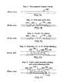
- FIGS. 1A–1Ishow processing steps for manufacturing a Leadless Plastic Chip Carrier (LPCC) with top and bottom partial etch resulting in a bottom etch cavity, according to a first embodiment of Applicants' prior art process;
- LPCCLeadless Plastic Chip Carrier
- FIGS. 2A–2Gshow processing steps for manufacturing a Leadless Plastic Chip Carrier (LPCC) with top and bottom partial etch incorporating standoff, according to a second embodiment of Applicants' prior art process;
- LPCCLeadless Plastic Chip Carrier
- FIGS. 3A–3Hshow processing steps for manufacturing a Leadless Plastic Chip Carrier (LPCC) with top side partial etch and solder ball attachment, according to a third embodiment of Applicants' prior art process;
- LPCCLeadless Plastic Chip Carrier
- FIGS. 4A–4Ishow processing steps for manufacturing a Leadless Plastic Chip Carrier (LPCC) with top side partial etch incorporating standoff, according to a fourth embodiment of Applicants' prior art process;
- LPCCLeadless Plastic Chip Carrier
- FIGS. 5A–5Jshow processing steps for manufacturing a Leadless Plastic Chip Carrier (LPCC) with bottom side partial etch, according to a fifth embodiment of Applicants' prior art process;
- LPCCLeadless Plastic Chip Carrier
- FIGS. 6A–6Hshow processing steps for manufacturing a Leadless Plastic Chip Carrier (LPCC) with etch back and special attachment features, according to the present invention
- FIG. 7is a bottom plan view of a single row IC package manufactured in accordance with the process of FIGS. 6A–6H ;
- FIGS. 8A and 8Bare bottom plan views of array type IC packages manufactured in accordance with the process of FIGS. 6A–6H .
- FIG. 9is a bottom plan view of an array type IC package according to the present invention, showing a pair of concentric rings.
- Applicants' prior Leadless Plastic Chip Carrier with Etch Back Singulation (LPCCEBS) processas described in copending application Ser. No. 09/288,352 is an improvement over Applicants' LPCC process as set forth in co-pending application Ser. No. 09/095,803.
- the present inventionrelates to an improvement in Applicants' prior LPCC methodology.
- FIGS. 1 to 5which set forth Applicants' LPCCEBS process. Where possible, the same reference numerals have been used in this application to denote identical features described in Applicants' earlier applications. Reference may be had to Applicants' co-pending applications for additional details concerning processing steps which are common to Applicants' processes.
- FIGS. 1A–1Ishow steps in the manufacture of an LPCCEBS according to a first embodiment of the invention disclosed in copending application Ser. No. 09/288,352—namely, with top and bottom side partial etch and bottom etch cavity.
- an elevation viewis provided of a copper panel substrate which forms the raw material of the leadframe strip 100 .
- the leadframe strip 100is divided into a plurality of sections, each of which incorporates a plurality of leadframe units in an array (e.g. 3 ⁇ 3 array, 5 ⁇ 5 array, etc.). Only one such unit is depicted in the elevation view of FIG. 1A , portions of adjacent units being shown by stippled lines.
- the leadframe strip 100is subjected to a partial etch on both top and bottom sides ( FIG. 1B ) to pattern the contact pads 203 and die attach pad 202 .
- the strip 100is plated with silver (Ag) or nickel/palladium (Ni/Pd) to facilitate wire bonding ( FIG. 1C ).
- a singulated semiconductor die 206is conventionally mounted via epoxy (or other means) to the die attach pad 202 , and the epoxy is cured. Gold wires 205 are then bonded between the semiconductor die 206 and peripheral leads or contacts 203 .
- the leadframe 100is then molded using a modified mold with the bottom cavity being a flat plate, and subsequently cured, as discussed in Applicants' application Ser. No. 09/095,803.
- the leadframe 100 after the foregoing stepsis as shown in FIG. 1D , which includes overmold 401 of cured plastic or epoxy.
- a wet film layer of photoresist 402is printed onto the bottom of leadframe 100 so as to cover portions of the bottom surface which are to be protected from etchant (i.e. positive photoresist).
- etchanti.e. positive photoresist
- the photoresistis then developed (cured) using conventional means ( FIG. 1E ).
- the leadframe 100is then subjected to a final etching via full immersion ( FIG. 1F ) which exposes an array or perimeter pattern of exposed contact pads 203 and the die attach pad 206 .
- the photoresist layer 402is then stripped using conventional means ( FIG. 1G ), resulting in small protrusions below the molded body for contact pads 203 .
- the leadframe strip 100is coated with either electroless gold or solder dip to facilitate pad soldering ( FIG. 1H ).
- barrel plated solder or chemically passivated bare coppermay be used for terminal finishing.
- the pads 203 and 202are fully isolated and exposed. Singulation of the individual units from the full leadframe array strip 100 may then be performed either by saw singulation or die punching ( FIG. 11 ).
- FIGS. 2A–2Gis similar to that of FIGS. 1A-11 , except that the partial etch ( FIG. 2B ) is a “mirror image” partial etch which results in a “standoff” structure, rather than being an offset pattern as shown in FIG. 1B . Consequently, no photoresist application is required following the mold step ( FIG. 2D ) and prior to the final etch back step ( FIG. 2E ).
- FIGS. 3A–3Hshow a single side partial etch process wherein, after the final full immersion etch and electroless gold plating ( FIGS. 3E and 3F ), the pads 203 are above the mold line so that solder balls 203 A are required to be attached in order to allow board mounting.
- FIGS. 4A–4Ishow a single side first partial etch with standoff (similar in this respect to the process of FIG. 2 ).
- a layer of photoresist 402is applied ( FIG. 4E ) and patterned, prior to the final etch back step ( FIG. 4F ).
- the steps depicted in FIGS. 3 and 4are similar to the steps discussed above and illustrated in FIGS. 1 and 2 , respectively.
- FIGS. 5A–5Jshow steps according to the etch back process of Applicants' prior invention, for fabricating an LPCC with multi-row partial lead isolation.
- a copper panelis provided, to which photoresist 502 is applied and patterned for a “first level” connect ( FIG. 5B ).
- An electrolytic plat of Cu/Ni/Auis applied to portions of the leadframe strip not covered by photoresist ( FIG. 5C ).
- the photoresistis then stripped ( FIG. 5D ), resulting in the structure of FIG. 5D with contact pads 203 and attach pad 202 .
- a layer of negative photoresist 504is applied and patterned for a “second level” connect ( FIG. 5E ).
- a pre-etch stepis then performed ( FIG. 5F ) to create contact and attach pad protrusions on the bottom of the structure.
- the photoresist 504is then stripped and the structure is cleaned ( FIG. 5G ).
- the semiconductor 206is attached to the pad 202 , gold wire bonds 203 are attached to the multi-row leads 203 and the structure is encapsulated as discussed above in mold 401 , such that the contact pad and attach pad protrusions remain exposed ( FIG. 5H ).
- a final etch backis performed ( FIG. 51 ) and the individual units are singulated. It will be noted that the steps in Applicants' prior LPCC process of saw singulating between the inner and outer rows of leads, is eliminated. Also, as with the embodiments of FIGS. 1 to 4 , post mold deflashing and cleaning has been eliminated.
- FIGS. 6 , 7 and 8showing the improvements which constitute the present invention.
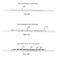
- an elevation viewis provided of a copper panel substrate which forms the raw material of leadframe strip 100 having thickness of approximately 5 mils.
- the leadframe stripis divided into a plurality of sections, each of which incorporates a plurality of leadframe units in an array (e.g. 3 ⁇ 3 array, 5 ⁇ 5 array, etc.). Only one such unit is depicted in the elevation view of FIG. 6A , portions of adjacent units being shown by stippled lines.
- the leadframe strip 100is covered with a photoresist mask 102 ( FIG. 6B ) in order to mask predetermined areas from subsequent multiple deposition steps ( FIG. 6C ).
- the leadframe strip 100is then subjected to an etching process to create the contact pads 203 , power or ground ring attachment 204 and die attach pad 202 ( FIG. 6D ).
- the ring 204can be either a power or a ground ring 204 .
- One feature of the present inventionis the deliberate deposition of the photoresist mask 102 in only a very thin layer (e.g. 2 mils) such that each contact pad 203 is plated up into a columnar shape as it flows over the photoresist mask, resulting in a “mushroom cap” or rivet shape ( FIGS. 6D and 6F ).
- the shape of the contact pads 203is such that they are capable of being locked into the mold body thereby providing superior board mount reliability. It is also contemplated that a “funnel” shape may be provided for the contact pads 203 by incorporating an angle on the photoresist mask.
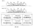
- options A-1 and A-2a layer of flash Cu (50 microinches) is provided over the Cu substrate for creating an etch down cavity following post etching (discussed in greater detail below with reference to FIG. 6F ) for attaching solder balls (also discussed below with reference to FIG. 6G ).
- An etch barrier layer of Au (20 microinches)is then deposited, followed by layers of Ni (40 microinches), and Cu (3-4 mils).
- option A-1final layers of Ni (40 microinches) and Au (20 microinches) are deposited whereas in Option A-2 a final layer of Ag is deposited (100-300 microinches).
- the initial flash Cu depositionis omitted, and in Options C-1 and C-2 the etch barrier of Au and subsequent Ni deposition are replaced by an etch barrier of tin (100–300 microinches).
- a singulated semiconductor die 206is conventionally mounted via epoxy (or other means) to the die attach pad 202 , and the epoxy is cured. Gold wires 205 are then bonded between the semiconductor die 206 and peripheral leads or contacts 203 .
- the leadframe 100is then molded using a modified mold with the bottom cavity being a flat plate, and subsequently cured, as discussed in Applicants' application Ser. No. 09/095,803.
- the leadframe 100 after the foregoing stepsis as shown in FIG. 6E , which includes overmold 401 of cured plastic or epoxy (0.8 mm).
- the leadframe 100is then subjected to a final alkaline etching via full immersion ( FIG. 6F ) which exposes an array or perimeter pattern of exposed contact pads 203 , power/ground ring 204 and the die attach pad 206 .
- a final alkaline etching via full immersionFIG. 6F
- an etch down cavity 203 Bis left after etching away the flash Cu, for attachment of solder balls 203 A to contact pads 203 , as shown in FIG. 6G .
- the power/ground ring 204 and die attach pad 202(which also functions as a ground plane) are fully isolated and exposed.
- Singulation of the individual units from the full leadframe array strip 100may then be performed either by saw singulation or die punching resulting in the final configuration of FIG. 6H . Since the entire LPCC contains short circuit connections prior to singulation, it is contemplated that the multiple circuits may be gang tested before singulation.
- the fabrication process of the present inventionmay alternatively omit the solder ball attachment step, as shown in Options B and C.
- FIG. 7is a bottom plan view of the assembled IC package according to the present invention, with a single row of I/O contacts, while FIGS. 8A and 8B show array type packages manufactured in accordance with the process of FIGS. 6A–6H .
- the contact pads 203are round, whereas in FIG. 8B the contact pads are rectangular.
- the power/ground ring 204 and the interlocking pattern of the die attach pad/ground plane 202are clearly shown.
- FIG. 9is a bottom plan view according to yet another embodiment of the present invention, with three rows of contact pads 203 , and a pair of concentric rings 204 .
- one of the rings 204is a power ring and the other is a ground ring.
- the two ringsmay be present, one being a power ring and the other being a ground ring. All such embodiments are believed to be within the sphere and scope of the invention as set forth in the claims appended hereto.
Landscapes
- Engineering & Computer Science (AREA)
- Physics & Mathematics (AREA)
- Condensed Matter Physics & Semiconductors (AREA)
- General Physics & Mathematics (AREA)
- Computer Hardware Design (AREA)
- Microelectronics & Electronic Packaging (AREA)
- Power Engineering (AREA)
- Manufacturing & Machinery (AREA)
- Lead Frames For Integrated Circuits (AREA)
- Semiconductor Integrated Circuits (AREA)
Abstract
Description
Claims (19)
Priority Applications (1)
| Application Number | Priority Date | Filing Date | Title |
|---|---|---|---|
| US11/123,489US6995460B1 (en) | 1998-06-10 | 2005-05-06 | Leadless plastic chip carrier with etch back pad singulation |
Applications Claiming Priority (4)
| Application Number | Priority Date | Filing Date | Title |
|---|---|---|---|
| US09/095,803US6229200B1 (en) | 1998-06-10 | 1998-06-10 | Saw-singulated leadless plastic chip carrier |
| US09/288,352US6498099B1 (en) | 1998-06-10 | 1999-04-08 | Leadless plastic chip carrier with etch back pad singulation |
| US09/802,678US6933594B2 (en) | 1998-06-10 | 2001-03-09 | Leadless plastic chip carrier with etch back pad singulation |
| US11/123,489US6995460B1 (en) | 1998-06-10 | 2005-05-06 | Leadless plastic chip carrier with etch back pad singulation |
Related Parent Applications (1)
| Application Number | Title | Priority Date | Filing Date |
|---|---|---|---|
| US09/802,678ContinuationUS6933594B2 (en) | 1998-06-10 | 2001-03-09 | Leadless plastic chip carrier with etch back pad singulation |
Publications (1)
| Publication Number | Publication Date |
|---|---|
| US6995460B1true US6995460B1 (en) | 2006-02-07 |
Family
ID=34991929
Family Applications (4)
| Application Number | Title | Priority Date | Filing Date |
|---|---|---|---|
| US10/353,241Expired - LifetimeUS6989294B1 (en) | 1998-06-10 | 2003-01-28 | Leadless plastic chip carrier with etch back pad singulation |
| US10/697,339Expired - LifetimeUS6946324B1 (en) | 1998-06-10 | 2003-10-30 | Process for fabricating a leadless plastic chip carrier |
| US10/757,499Expired - LifetimeUS6964918B1 (en) | 1998-06-10 | 2004-01-15 | Electronic components such as thin array plastic packages and process for fabricating same |
| US11/123,489Expired - LifetimeUS6995460B1 (en) | 1998-06-10 | 2005-05-06 | Leadless plastic chip carrier with etch back pad singulation |
Family Applications Before (3)
| Application Number | Title | Priority Date | Filing Date |
|---|---|---|---|
| US10/353,241Expired - LifetimeUS6989294B1 (en) | 1998-06-10 | 2003-01-28 | Leadless plastic chip carrier with etch back pad singulation |
| US10/697,339Expired - LifetimeUS6946324B1 (en) | 1998-06-10 | 2003-10-30 | Process for fabricating a leadless plastic chip carrier |
| US10/757,499Expired - LifetimeUS6964918B1 (en) | 1998-06-10 | 2004-01-15 | Electronic components such as thin array plastic packages and process for fabricating same |
Country Status (1)
| Country | Link |
|---|---|
| US (4) | US6989294B1 (en) |
Cited By (52)
| Publication number | Priority date | Publication date | Assignee | Title |
|---|---|---|---|---|
| US20050006737A1 (en)* | 2002-04-29 | 2005-01-13 | Shafidul Islam | Partially patterned lead frames and methods of making and using the same in semiconductor packaging |
| US20050196937A1 (en)* | 2004-03-05 | 2005-09-08 | Nicolas Daval | Methods for forming a semiconductor structure |
| US20050248016A1 (en)* | 2004-05-05 | 2005-11-10 | Cheng-Yen Huang | Chip-packaging with bonding options having a plurality of package substrates |
| US20060001130A1 (en)* | 2002-09-25 | 2006-01-05 | Shafidul Islam | Taped lead frames and methods of making and using the same in semiconductor packaging |
| US20060051912A1 (en)* | 2004-09-09 | 2006-03-09 | Ati Technologies Inc. | Method and apparatus for a stacked die configuration |
| US20060284290A1 (en)* | 2005-06-17 | 2006-12-21 | Joseph Cheng | Chip-package structure and fabrication process thereof |
| US20070052076A1 (en)* | 2002-04-29 | 2007-03-08 | Ramos Mary J | Partially Patterned Lead Frames and Methods of Making and Using the Same in Semiconductor Packaging |
| US20070108635A1 (en)* | 2005-04-28 | 2007-05-17 | Stats Chippac Ltd. | Integrated circuit package system |
| US20070235854A1 (en)* | 2006-03-30 | 2007-10-11 | Stats Chippac Ltd. | Integrated circuit package system with ground ring |
| US20080001263A1 (en)* | 2006-06-30 | 2008-01-03 | Stats Chippac Ltd. | Integrated circuit package system |
| US20080054421A1 (en)* | 2006-08-23 | 2008-03-06 | Stats Chippac Ltd. | Integrated circuit package system with interlock |
| US20080054490A1 (en)* | 2006-08-31 | 2008-03-06 | Ati Technologies Inc. | Flip-Chip Ball Grid Array Strip and Package |
| US20080099910A1 (en)* | 2006-08-31 | 2008-05-01 | Ati Technologies Inc. | Flip-Chip Semiconductor Package with Encapsulant Retaining Structure and Strip |
| US20080201943A1 (en)* | 2005-03-17 | 2008-08-28 | Hitachi Cable, Ltd. | Electronic device substrate and its fabrication method, and electronic device and its fabrication method |
| US20080258278A1 (en)* | 2002-04-29 | 2008-10-23 | Mary Jean Ramos | Partially patterned lead frames and methods of making and using the same in semiconductor packaging |
| US20090230524A1 (en)* | 2008-03-14 | 2009-09-17 | Pao-Huei Chang Chien | Semiconductor chip package having ground and power regions and manufacturing methods thereof |
| US20100044843A1 (en)* | 2008-08-21 | 2010-02-25 | Advanced Semiconductor Engineering, Inc. | Advanced quad flat non-leaded package structure and manufacturing method thereof |
| US20100127363A1 (en)* | 2006-04-28 | 2010-05-27 | Utac Thai Limited | Very extremely thin semiconductor package |
| US7790512B1 (en) | 2007-11-06 | 2010-09-07 | Utac Thai Limited | Molded leadframe substrate semiconductor package |
| US20100258934A1 (en)* | 2009-04-10 | 2010-10-14 | Advanced Semiconductor Engineering, Inc. | Advanced quad flat non-leaded package structure and manufacturing method thereof |
| US20100311208A1 (en)* | 2008-05-22 | 2010-12-09 | Utac Thai Limited | Method and apparatus for no lead semiconductor package |
| US20100327432A1 (en)* | 2006-09-26 | 2010-12-30 | Utac Thai Limited | Package with heat transfer |
| US20110018111A1 (en)* | 2009-07-23 | 2011-01-27 | Utac Thai Limited | Leadframe feature to minimize flip-chip semiconductor die collapse during flip-chip reflow |
| US20110039371A1 (en)* | 2008-09-04 | 2011-02-17 | Utac Thai Limited | Flip chip cavity package |
| US20110111562A1 (en)* | 2002-04-29 | 2011-05-12 | San Antonio Romarico S | Partially Patterned Lead Frames and Methods of Making and Using the Same in Semiconductor Packaging |
| US20110133319A1 (en)* | 2009-12-04 | 2011-06-09 | Utac Thai Limited | Auxiliary leadframe member for stabilizing the bond wire process |
| US20110147931A1 (en)* | 2006-04-28 | 2011-06-23 | Utac Thai Limited | Lead frame land grid array with routing connector trace under unit |
| US20110163430A1 (en)* | 2010-01-06 | 2011-07-07 | Advanced Semiconductor Engineering, Inc. | Leadframe Structure, Advanced Quad Flat No Lead Package Structure Using the Same, and Manufacturing Methods Thereof |
| US20110198752A1 (en)* | 2006-04-28 | 2011-08-18 | Utac Thai Limited | Lead frame ball grid array with traces under die |
| US8013437B1 (en) | 2006-09-26 | 2011-09-06 | Utac Thai Limited | Package with heat transfer |
| US20110221051A1 (en)* | 2010-03-11 | 2011-09-15 | Utac Thai Limited | Leadframe based multi terminal ic package |
| US20110233752A1 (en)* | 2010-03-26 | 2011-09-29 | Zigmund Ramirez Camacho | Integrated circuit packaging system with an intermediate pad and method of manufacture thereof |
| US20110233753A1 (en)* | 2010-03-26 | 2011-09-29 | Zigmund Ramirez Camacho | Integrated circuit packaging system with leads and method of manufacture thereof |
| US20110232693A1 (en)* | 2009-03-12 | 2011-09-29 | Utac Thai Limited | Metallic solderability preservation coating on metal part of semiconductor package to prevent oxide |
| US8089145B1 (en)* | 2008-11-17 | 2012-01-03 | Amkor Technology, Inc. | Semiconductor device including increased capacity leadframe |
| US20120326284A1 (en)* | 2011-06-23 | 2012-12-27 | Byung Tai Do | Integrated circuit packaging system with thermal emission and method of manufacture thereof |
| US8460970B1 (en) | 2006-04-28 | 2013-06-11 | Utac Thai Limited | Lead frame ball grid array with traces under die having interlocking features |
| US8461694B1 (en) | 2006-04-28 | 2013-06-11 | Utac Thai Limited | Lead frame ball grid array with traces under die having interlocking features |
| US8871571B2 (en) | 2010-04-02 | 2014-10-28 | Utac Thai Limited | Apparatus for and methods of attaching heat slugs to package tops |
| US8917521B2 (en) | 2010-04-28 | 2014-12-23 | Advanpack Solutions Pte Ltd. | Etch-back type semiconductor package, substrate and manufacturing method thereof |
| US9000590B2 (en) | 2012-05-10 | 2015-04-07 | Utac Thai Limited | Protruding terminals with internal routing interconnections semiconductor device |
| US9006034B1 (en) | 2012-06-11 | 2015-04-14 | Utac Thai Limited | Post-mold for semiconductor package having exposed traces |
| CN104681527A (en)* | 2013-12-03 | 2015-06-03 | 上海北京大学微电子研究院 | QFN (Quad Flat No-lead Package) package framework structure |
| US9082607B1 (en) | 2006-12-14 | 2015-07-14 | Utac Thai Limited | Molded leadframe substrate semiconductor package |
| US9355940B1 (en) | 2009-12-04 | 2016-05-31 | Utac Thai Limited | Auxiliary leadframe member for stabilizing the bond wire process |
| US9449905B2 (en) | 2012-05-10 | 2016-09-20 | Utac Thai Limited | Plated terminals with routing interconnections semiconductor device |
| US9570381B2 (en) | 2015-04-02 | 2017-02-14 | Advanced Semiconductor Engineering, Inc. | Semiconductor packages and related manufacturing methods |
| US9761435B1 (en) | 2006-12-14 | 2017-09-12 | Utac Thai Limited | Flip chip cavity package |
| US9805955B1 (en) | 2015-11-10 | 2017-10-31 | UTAC Headquarters Pte. Ltd. | Semiconductor package with multiple molding routing layers and a method of manufacturing the same |
| US10242934B1 (en) | 2014-05-07 | 2019-03-26 | Utac Headquarters Pte Ltd. | Semiconductor package with full plating on contact side surfaces and methods thereof |
| US10242953B1 (en) | 2015-05-27 | 2019-03-26 | Utac Headquarters PTE. Ltd | Semiconductor package with plated metal shielding and a method thereof |
| US10276477B1 (en) | 2016-05-20 | 2019-04-30 | UTAC Headquarters Pte. Ltd. | Semiconductor package with multiple stacked leadframes and a method of manufacturing the same |
Families Citing this family (70)
| Publication number | Priority date | Publication date | Assignee | Title |
|---|---|---|---|---|
| US6229200B1 (en) | 1998-06-10 | 2001-05-08 | Asat Limited | Saw-singulated leadless plastic chip carrier |
| US7247526B1 (en)* | 1998-06-10 | 2007-07-24 | Asat Ltd. | Process for fabricating an integrated circuit package |
| US8330270B1 (en) | 1998-06-10 | 2012-12-11 | Utac Hong Kong Limited | Integrated circuit package having a plurality of spaced apart pad portions |
| US7270867B1 (en)* | 1998-06-10 | 2007-09-18 | Asat Ltd. | Leadless plastic chip carrier |
| JP4611569B2 (en)* | 2001-05-30 | 2011-01-12 | ルネサスエレクトロニクス株式会社 | Lead frame and method for manufacturing semiconductor device |
| SG139508A1 (en)* | 2001-09-10 | 2008-02-29 | Micron Technology Inc | Wafer dicing device and method |
| SG102639A1 (en)* | 2001-10-08 | 2004-03-26 | Micron Technology Inc | Apparatus and method for packing circuits |
| SG142115A1 (en) | 2002-06-14 | 2008-05-28 | Micron Technology Inc | Wafer level packaging |
| JP2004071899A (en)* | 2002-08-07 | 2004-03-04 | Sanyo Electric Co Ltd | Circuit device and its producing method |
| JP2004200464A (en)* | 2002-12-19 | 2004-07-15 | Anden | Metal circuit board |
| US20040217488A1 (en)* | 2003-05-02 | 2004-11-04 | Luechinger Christoph B. | Ribbon bonding |
| SG119185A1 (en) | 2003-05-06 | 2006-02-28 | Micron Technology Inc | Method for packaging circuits and packaged circuits |
| MY140980A (en)* | 2003-09-23 | 2010-02-12 | Unisem M Berhad | Semiconductor package |
| US7595225B1 (en)* | 2004-10-05 | 2009-09-29 | Chun Ho Fan | Leadless plastic chip carrier with contact standoff |
| US7671451B2 (en)* | 2004-11-12 | 2010-03-02 | Chippac, Inc. | Semiconductor package having double layer leadframe |
| TWI249209B (en)* | 2004-12-22 | 2006-02-11 | Siliconware Precision Industries Co Ltd | Semiconductor package with support structure and fabrication method thereof |
| US7507605B2 (en)* | 2004-12-30 | 2009-03-24 | Texas Instruments Incorporated | Low cost lead-free preplated leadframe having improved adhesion and solderability |
| WO2006091032A1 (en)* | 2005-02-23 | 2006-08-31 | Lg Micron Ltd. | Lead frame |
| US8022522B1 (en) | 2005-04-01 | 2011-09-20 | Marvell International Ltd. | Semiconductor package |
| US20070130759A1 (en)* | 2005-06-15 | 2007-06-14 | Gem Services, Inc. | Semiconductor device package leadframe formed from multiple metal layers |
| US20090002969A1 (en)* | 2007-06-27 | 2009-01-01 | Rf Micro Devices, Inc. | Field barrier structures within a conformal shield |
| US8053872B1 (en) | 2007-06-25 | 2011-11-08 | Rf Micro Devices, Inc. | Integrated shield for a no-lead semiconductor device package |
| US8062930B1 (en) | 2005-08-08 | 2011-11-22 | Rf Micro Devices, Inc. | Sub-module conformal electromagnetic interference shield |
| US8959762B2 (en) | 2005-08-08 | 2015-02-24 | Rf Micro Devices, Inc. | Method of manufacturing an electronic module |
| TW200737479A (en)* | 2005-11-03 | 2007-10-01 | Koninkl Philips Electronics Nv | Surface treatments for contact pads used in semiconductor chip packages and methods of providing such surface treatments |
| US7679162B2 (en)* | 2005-12-19 | 2010-03-16 | Silicon Laboratories Inc. | Integrated current sensor package |
| TWI286375B (en)* | 2006-03-24 | 2007-09-01 | Chipmos Technologies Inc | Leadless semiconductor package with electroplated layer embedded in encapsulant and the method for fabricating the same |
| US7990132B2 (en)* | 2006-06-30 | 2011-08-02 | Silicon Laboratories Inc. | Current sensor including an integrated circuit die including a first and second coil |
| US7777353B2 (en)* | 2006-08-15 | 2010-08-17 | Yamaha Corporation | Semiconductor device and wire bonding method therefor |
| US7662672B2 (en)* | 2006-10-13 | 2010-02-16 | Chipmos Technologies (Bermuda) Ltd. | Manufacturing process of leadframe-based BGA packages |
| KR100827388B1 (en)* | 2006-12-19 | 2008-05-07 | 주식회사 씨오엘테크 | Manufacturing method of semiconductor package |
| US8124461B2 (en)* | 2006-12-27 | 2012-02-28 | Mediatek Inc. | Method for manufacturing leadframe, packaging method for using the leadframe and semiconductor package product |
| CN101211794A (en)* | 2006-12-27 | 2008-07-02 | 联发科技股份有限公司 | Method for packaging semiconductor element, method for manufacturing lead frame and semiconductor packaging product |
| US7834435B2 (en)* | 2006-12-27 | 2010-11-16 | Mediatek Inc. | Leadframe with extended pad segments between leads and die pad, and leadframe package using the same |
| CN100555592C (en)* | 2007-02-08 | 2009-10-28 | 百慕达南茂科技股份有限公司 | Chip-packaging structure and preparation method thereof |
| TWI358809B (en)* | 2007-06-13 | 2012-02-21 | Siliconware Precision Industries Co Ltd | Semiconductor package and fabrication method there |
| TWI385774B (en)* | 2007-12-26 | 2013-02-11 | Mediatek Inc | Lead frame package and lead frame |
| US7728578B2 (en)* | 2008-05-15 | 2010-06-01 | Silicon Laboratories Inc. | Method and apparatus for high current measurement |
| US20110042794A1 (en)* | 2008-05-19 | 2011-02-24 | Tung-Hsien Hsieh | Qfn semiconductor package and circuit board structure adapted for the same |
| JP2009302095A (en)* | 2008-06-10 | 2009-12-24 | Seiko Epson Corp | Semiconductor device and method for manufacturing the same |
| US20100127380A1 (en)* | 2008-11-26 | 2010-05-27 | Manolito Galera | Leadframe free leadless array semiconductor packages |
| TWI389228B (en)* | 2009-01-23 | 2013-03-11 | Everlight Electronics Co Ltd | Electronic device |
| CN101807561B (en)* | 2009-02-18 | 2011-10-19 | 亿光电子工业股份有限公司 | Electronic component |
| US7858443B2 (en)* | 2009-03-09 | 2010-12-28 | Utac Hong Kong Limited | Leadless integrated circuit package having standoff contacts and die attach pad |
| US8133759B2 (en)* | 2009-04-28 | 2012-03-13 | Macronix International Co., Ltd. | Leadframe |
| JP5195647B2 (en)* | 2009-06-01 | 2013-05-08 | セイコーエプソン株式会社 | Lead frame manufacturing method and semiconductor device manufacturing method |
| US20110108966A1 (en)* | 2009-11-11 | 2011-05-12 | Henry Descalzo Bathan | Integrated circuit packaging system with concave trenches and method of manufacture thereof |
| TWI392066B (en)* | 2009-12-28 | 2013-04-01 | 矽品精密工業股份有限公司 | Package structure and fabrication method thereof |
| TWI427716B (en) | 2010-06-04 | 2014-02-21 | 矽品精密工業股份有限公司 | Semiconductor package without carrier and method of fabricating the same |
| US8716873B2 (en) | 2010-07-01 | 2014-05-06 | United Test And Assembly Center Ltd. | Semiconductor packages and methods of packaging semiconductor devices |
| TWI433243B (en) | 2010-07-12 | 2014-04-01 | 矽品精密工業股份有限公司 | Semiconductor package without chip carrier and fabrication method thereof |
| US9137934B2 (en) | 2010-08-18 | 2015-09-15 | Rf Micro Devices, Inc. | Compartmentalized shielding of selected components |
| TWI464852B (en)* | 2010-11-03 | 2014-12-11 | Mediatek Inc | Quad flat no-lead package and board for quad flat no-lead packages |
| US8835226B2 (en) | 2011-02-25 | 2014-09-16 | Rf Micro Devices, Inc. | Connection using conductive vias |
| US9627230B2 (en) | 2011-02-28 | 2017-04-18 | Qorvo Us, Inc. | Methods of forming a microshield on standard QFN package |
| US8604596B2 (en) | 2011-03-24 | 2013-12-10 | Stats Chippac Ltd. | Integrated circuit packaging system with locking interconnects and method of manufacture thereof |
| TWI453872B (en) | 2011-06-23 | 2014-09-21 | 矽品精密工業股份有限公司 | Semiconductor package and fabrication method thereof |
| TWI455269B (en)* | 2011-07-20 | 2014-10-01 | Chipmos Technologies Inc | Chip package structure and manufacturing method thereof |
| US9590155B2 (en)* | 2012-06-06 | 2017-03-07 | Cree, Inc. | Light emitting devices and substrates with improved plating |
| US9807890B2 (en) | 2013-05-31 | 2017-10-31 | Qorvo Us, Inc. | Electronic modules having grounded electromagnetic shields |
| US9620480B1 (en) | 2013-06-28 | 2017-04-11 | STATS ChipPAC Pte. Ltd | Integrated circuit packaging system with unplated leadframe and method of manufacture thereof |
| US9190349B1 (en) | 2013-06-28 | 2015-11-17 | Stats Chippac Ltd. | Integrated circuit packaging system with leadframe and method of manufacture thereof |
| US9177897B1 (en) | 2013-06-28 | 2015-11-03 | Stats Chippac Ltd. | Integrated circuit packaging system with trace protection layer and method of manufacture thereof |
| US9947636B2 (en)* | 2014-06-02 | 2018-04-17 | Stmicroelectronics, Inc. | Method for making semiconductor device with lead frame made from top and bottom components and related devices |
| TWI627380B (en)* | 2016-11-23 | 2018-06-21 | 綠點高新科技股份有限公司 | Method And System For Estimating Contour Of A Surface Of A 3D Object |
| CN108242403A (en)* | 2016-12-27 | 2018-07-03 | 冠宝科技股份有限公司 | Substrate-free semiconductor package manufacturing method |
| US11127689B2 (en) | 2018-06-01 | 2021-09-21 | Qorvo Us, Inc. | Segmented shielding using wirebonds |
| US11219144B2 (en) | 2018-06-28 | 2022-01-04 | Qorvo Us, Inc. | Electromagnetic shields for sub-modules |
| US11114363B2 (en) | 2018-12-20 | 2021-09-07 | Qorvo Us, Inc. | Electronic package arrangements and related methods |
| US11515282B2 (en) | 2019-05-21 | 2022-11-29 | Qorvo Us, Inc. | Electromagnetic shields with bonding wires for sub-modules |
Citations (29)
| Publication number | Priority date | Publication date | Assignee | Title |
|---|---|---|---|---|
| JPS59208756A (en) | 1983-05-12 | 1984-11-27 | Sony Corp | Manufacture of semiconductor device package |
| US4530152A (en) | 1982-04-01 | 1985-07-23 | Compagnie Industrielle Des Telecommunications Cit-Alcatel | Method for encapsulating semiconductor components using temporary substrates |
| US4685998A (en) | 1984-03-22 | 1987-08-11 | Thomson Components - Mostek Corp. | Process of forming integrated circuits with contact pads in a standard array |
| US5066831A (en) | 1987-10-23 | 1991-11-19 | Honeywell Inc. | Universal semiconductor chip package |
| US5293072A (en) | 1990-06-25 | 1994-03-08 | Fujitsu Limited | Semiconductor device having spherical terminals attached to the lead frame embedded within the package body |
| US5444301A (en) | 1993-06-23 | 1995-08-22 | Goldstar Electron Co. Ltd. | Semiconductor package and method for manufacturing the same |
| US5457340A (en) | 1992-12-07 | 1995-10-10 | Integrated Device Technology, Inc. | Leadframe with power and ground planes |
| US5710695A (en) | 1995-11-07 | 1998-01-20 | Vlsi Technology, Inc. | Leadframe ball grid array package |
| US5777382A (en) | 1995-12-19 | 1998-07-07 | Texas Instruments Incorporated | Plastic packaging for a surface mounted integrated circuit |
| US5900676A (en) | 1996-08-19 | 1999-05-04 | Samsung Electronics Co., Ltd. | Semiconductor device package structure having column leads and a method for production thereof |
| US5976912A (en) | 1994-03-18 | 1999-11-02 | Hitachi Chemical Company, Ltd. | Fabrication process of semiconductor package and semiconductor package |
| US6001671A (en) | 1996-04-18 | 1999-12-14 | Tessera, Inc. | Methods for manufacturing a semiconductor package having a sacrificial layer |
| US6057601A (en) | 1998-11-27 | 2000-05-02 | Express Packaging Systems, Inc. | Heat spreader with a placement recess and bottom saw-teeth for connection to ground planes on a thin two-sided single-core BGA substrate |
| US6081029A (en) | 1998-03-12 | 2000-06-27 | Matsushita Electronics Corporation | Resin encapsulated semiconductor device having a reduced thickness and improved reliability |
| US6194786B1 (en) | 1997-09-19 | 2001-02-27 | Texas Instruments Incorporated | Integrated circuit package providing bond wire clearance over intervening conductive regions |
| US6229200B1 (en) | 1998-06-10 | 2001-05-08 | Asat Limited | Saw-singulated leadless plastic chip carrier |
| US6238952B1 (en) | 2000-02-29 | 2001-05-29 | Advanced Semiconductor Engineering, Inc. | Low-pin-count chip package and manufacturing method thereof |
| US6294100B1 (en) | 1998-06-10 | 2001-09-25 | Asat Ltd | Exposed die leadless plastic chip carrier |
| US6306685B1 (en) | 2000-02-01 | 2001-10-23 | Advanced Semiconductor Engineering, Inc. | Method of molding a bump chip carrier and structure made thereby |
| US6372539B1 (en) | 2000-03-20 | 2002-04-16 | National Semiconductor Corporation | Leadless packaging process using a conductive substrate |
| US6459163B1 (en) | 2001-03-21 | 2002-10-01 | United Test Center, Inc. | Semiconductor device and method for fabricating the same |
| US6498099B1 (en) | 1998-06-10 | 2002-12-24 | Asat Ltd. | Leadless plastic chip carrier with etch back pad singulation |
| US20030015780A1 (en) | 2001-07-19 | 2003-01-23 | In Ku Kang | Bumped chip carrier package using lead frame and method for manufacturing the same |
| US6528877B2 (en) | 1999-02-08 | 2003-03-04 | Infineon Technologies Ag | Semiconductor component having a chip carrier with openings for making contact |
| US6545347B2 (en) | 2001-03-06 | 2003-04-08 | Asat, Limited | Enhanced leadless chip carrier |
| US6586677B2 (en) | 1999-08-25 | 2003-07-01 | Amkor Technology, Inc. | Plastic integrated circuit device package having exposed lead surface |
| US6585905B1 (en) | 1998-06-10 | 2003-07-01 | Asat Ltd. | Leadless plastic chip carrier with partial etch die attach pad |
| US6635957B2 (en) | 1998-06-10 | 2003-10-21 | Asat Ltd. | Leadless plastic chip carrier with etch back pad singulation and die attach pad array |
| US6821821B2 (en) | 1996-04-18 | 2004-11-23 | Tessera, Inc. | Methods for manufacturing resistors using a sacrificial layer |
Family Cites Families (5)
| Publication number | Priority date | Publication date | Assignee | Title |
|---|---|---|---|---|
| US5726502A (en)* | 1996-04-26 | 1998-03-10 | Motorola, Inc. | Bumped semiconductor device with alignment features and method for making the same |
| TW322613B (en)* | 1997-03-10 | 1997-12-11 | guang-long Lin | Continuous method of implementing solder bump on semiconductor wafer electrode |
| US6872661B1 (en)* | 1998-06-10 | 2005-03-29 | Asat Ltd. | Leadless plastic chip carrier with etch back pad singulation and die attach pad array |
| US6489557B2 (en) | 1999-08-30 | 2002-12-03 | Intel Corporation | Implementing micro BGA™ assembly techniques for small die |
| US6261864B1 (en)* | 2000-01-28 | 2001-07-17 | Advanced Semiconductor Engineering, Inc. | Low-pin-count chip package and manufacturing method thereof |
- 2003
- 2003-01-28USUS10/353,241patent/US6989294B1/ennot_activeExpired - Lifetime
- 2003-10-30USUS10/697,339patent/US6946324B1/ennot_activeExpired - Lifetime
- 2004
- 2004-01-15USUS10/757,499patent/US6964918B1/ennot_activeExpired - Lifetime
- 2005
- 2005-05-06USUS11/123,489patent/US6995460B1/ennot_activeExpired - Lifetime
Patent Citations (31)
| Publication number | Priority date | Publication date | Assignee | Title |
|---|---|---|---|---|
| US4530152A (en) | 1982-04-01 | 1985-07-23 | Compagnie Industrielle Des Telecommunications Cit-Alcatel | Method for encapsulating semiconductor components using temporary substrates |
| JPS59208756A (en) | 1983-05-12 | 1984-11-27 | Sony Corp | Manufacture of semiconductor device package |
| US4685998A (en) | 1984-03-22 | 1987-08-11 | Thomson Components - Mostek Corp. | Process of forming integrated circuits with contact pads in a standard array |
| US5066831A (en) | 1987-10-23 | 1991-11-19 | Honeywell Inc. | Universal semiconductor chip package |
| US5293072A (en) | 1990-06-25 | 1994-03-08 | Fujitsu Limited | Semiconductor device having spherical terminals attached to the lead frame embedded within the package body |
| US5457340A (en) | 1992-12-07 | 1995-10-10 | Integrated Device Technology, Inc. | Leadframe with power and ground planes |
| US5444301A (en) | 1993-06-23 | 1995-08-22 | Goldstar Electron Co. Ltd. | Semiconductor package and method for manufacturing the same |
| US5976912A (en) | 1994-03-18 | 1999-11-02 | Hitachi Chemical Company, Ltd. | Fabrication process of semiconductor package and semiconductor package |
| US5710695A (en) | 1995-11-07 | 1998-01-20 | Vlsi Technology, Inc. | Leadframe ball grid array package |
| US5777382A (en) | 1995-12-19 | 1998-07-07 | Texas Instruments Incorporated | Plastic packaging for a surface mounted integrated circuit |
| US6093584A (en) | 1996-04-18 | 2000-07-25 | Tessera, Inc. | Method for encapsulating a semiconductor package having apertures through a sacrificial layer and contact pads |
| US6294830B1 (en) | 1996-04-18 | 2001-09-25 | Tessera, Inc. | Microelectronic assembly with conductive terminals having an exposed surface through a dielectric layer |
| US6821821B2 (en) | 1996-04-18 | 2004-11-23 | Tessera, Inc. | Methods for manufacturing resistors using a sacrificial layer |
| US6001671A (en) | 1996-04-18 | 1999-12-14 | Tessera, Inc. | Methods for manufacturing a semiconductor package having a sacrificial layer |
| US5900676A (en) | 1996-08-19 | 1999-05-04 | Samsung Electronics Co., Ltd. | Semiconductor device package structure having column leads and a method for production thereof |
| US6194786B1 (en) | 1997-09-19 | 2001-02-27 | Texas Instruments Incorporated | Integrated circuit package providing bond wire clearance over intervening conductive regions |
| US6081029A (en) | 1998-03-12 | 2000-06-27 | Matsushita Electronics Corporation | Resin encapsulated semiconductor device having a reduced thickness and improved reliability |
| US6294100B1 (en) | 1998-06-10 | 2001-09-25 | Asat Ltd | Exposed die leadless plastic chip carrier |
| US6229200B1 (en) | 1998-06-10 | 2001-05-08 | Asat Limited | Saw-singulated leadless plastic chip carrier |
| US6498099B1 (en) | 1998-06-10 | 2002-12-24 | Asat Ltd. | Leadless plastic chip carrier with etch back pad singulation |
| US6635957B2 (en) | 1998-06-10 | 2003-10-21 | Asat Ltd. | Leadless plastic chip carrier with etch back pad singulation and die attach pad array |
| US6585905B1 (en) | 1998-06-10 | 2003-07-01 | Asat Ltd. | Leadless plastic chip carrier with partial etch die attach pad |
| US6057601A (en) | 1998-11-27 | 2000-05-02 | Express Packaging Systems, Inc. | Heat spreader with a placement recess and bottom saw-teeth for connection to ground planes on a thin two-sided single-core BGA substrate |
| US6528877B2 (en) | 1999-02-08 | 2003-03-04 | Infineon Technologies Ag | Semiconductor component having a chip carrier with openings for making contact |
| US6586677B2 (en) | 1999-08-25 | 2003-07-01 | Amkor Technology, Inc. | Plastic integrated circuit device package having exposed lead surface |
| US6306685B1 (en) | 2000-02-01 | 2001-10-23 | Advanced Semiconductor Engineering, Inc. | Method of molding a bump chip carrier and structure made thereby |
| US6238952B1 (en) | 2000-02-29 | 2001-05-29 | Advanced Semiconductor Engineering, Inc. | Low-pin-count chip package and manufacturing method thereof |
| US6372539B1 (en) | 2000-03-20 | 2002-04-16 | National Semiconductor Corporation | Leadless packaging process using a conductive substrate |
| US6545347B2 (en) | 2001-03-06 | 2003-04-08 | Asat, Limited | Enhanced leadless chip carrier |
| US6459163B1 (en) | 2001-03-21 | 2002-10-01 | United Test Center, Inc. | Semiconductor device and method for fabricating the same |
| US20030015780A1 (en) | 2001-07-19 | 2003-01-23 | In Ku Kang | Bumped chip carrier package using lead frame and method for manufacturing the same |
Non-Patent Citations (4)
| Title |
|---|
| U.S. Appl. No. 09/802,678, Neil McLellan et al., Leadless Plastic Chip Carrier With Etch Back Pad Singlulation, filed Mar. 9, 2001, currently pending. |
| U.S. Appl. No. 10/353,241, Neil McLellen et al., "Leadless Plastic Chip Carrier With Etch Back Pad Singulation", filed Jan. 28, 2003, currently pending. |
| U.S. Appl. No. 10/697,339, Neil McLellan et al., "Process for Fabricating a Leadless Plastic Chip Carrier", filed Oct. 30, 2003, currently pending. |
| U.S. Appl. No. 10/757,499, Chun Ho Fan et al., Electronic Components Such as Thin Array Plastic Packages and Process for Fabricating Same, filed Jan. 15, 2004, currently pending. |
Cited By (119)
| Publication number | Priority date | Publication date | Assignee | Title |
|---|---|---|---|---|
| US20050006737A1 (en)* | 2002-04-29 | 2005-01-13 | Shafidul Islam | Partially patterned lead frames and methods of making and using the same in semiconductor packaging |
| US7790500B2 (en) | 2002-04-29 | 2010-09-07 | Unisem (Mauritius) Holdings Limited | Partially patterned lead frames and methods of making and using the same in semiconductor packaging |
| US20110111562A1 (en)* | 2002-04-29 | 2011-05-12 | San Antonio Romarico S | Partially Patterned Lead Frames and Methods of Making and Using the Same in Semiconductor Packaging |
| US20050263864A1 (en)* | 2002-04-29 | 2005-12-01 | Shafidul Islam | Partially patterned lead frames and methods of making and using the same in semiconductor packaging |
| US8236612B2 (en) | 2002-04-29 | 2012-08-07 | Unisem (Mauritius) Holdings Limited | Partially patterned lead frames and methods of making and using the same in semiconductor packaging |
| US7622332B2 (en) | 2002-04-29 | 2009-11-24 | Unisem (Mauritius) Holdings Limited | Partially patterned lead frames and methods of making and using the same in semiconductor packaging |
| US7799611B2 (en) | 2002-04-29 | 2010-09-21 | Unisem (Mauritius) Holdings Limited | Partially patterned lead frames and methods of making and using the same in semiconductor packaging |
| US20080258278A1 (en)* | 2002-04-29 | 2008-10-23 | Mary Jean Ramos | Partially patterned lead frames and methods of making and using the same in semiconductor packaging |
| US20070052076A1 (en)* | 2002-04-29 | 2007-03-08 | Ramos Mary J | Partially Patterned Lead Frames and Methods of Making and Using the Same in Semiconductor Packaging |
| US20060001130A1 (en)* | 2002-09-25 | 2006-01-05 | Shafidul Islam | Taped lead frames and methods of making and using the same in semiconductor packaging |
| US7439097B2 (en) | 2002-09-25 | 2008-10-21 | Unisem (Mauritius) Holdings Limited | Taped lead frames and methods of making and using the same in semiconductor packaging |
| US20050196937A1 (en)* | 2004-03-05 | 2005-09-08 | Nicolas Daval | Methods for forming a semiconductor structure |
| US7701041B2 (en) | 2004-05-05 | 2010-04-20 | Faraday Technology Corp. | Chip-packaging with bonding options having a plurality of package substrates |
| US7196401B2 (en)* | 2004-05-05 | 2007-03-27 | Faraday Technology Corp. | Chip-packaging with bonding options having a plurality of package substrates |
| US20060197208A1 (en)* | 2004-05-05 | 2006-09-07 | Cheng-Yen Huang | Chip-packaging with bonding options having a plurality of package substrates |
| US20050248016A1 (en)* | 2004-05-05 | 2005-11-10 | Cheng-Yen Huang | Chip-packaging with bonding options having a plurality of package substrates |
| US20060051912A1 (en)* | 2004-09-09 | 2006-03-09 | Ati Technologies Inc. | Method and apparatus for a stacked die configuration |
| US20080201943A1 (en)* | 2005-03-17 | 2008-08-28 | Hitachi Cable, Ltd. | Electronic device substrate and its fabrication method, and electronic device and its fabrication method |
| US8230591B2 (en)* | 2005-03-17 | 2012-07-31 | Hitachi Cable, Ltd. | Method for fabricating an electronic device substrate |
| US20070108635A1 (en)* | 2005-04-28 | 2007-05-17 | Stats Chippac Ltd. | Integrated circuit package system |
| US20060284290A1 (en)* | 2005-06-17 | 2006-12-21 | Joseph Cheng | Chip-package structure and fabrication process thereof |
| US20070235854A1 (en)* | 2006-03-30 | 2007-10-11 | Stats Chippac Ltd. | Integrated circuit package system with ground ring |
| US7671463B2 (en) | 2006-03-30 | 2010-03-02 | Stats Chippac Ltd. | Integrated circuit package system with ground ring |
| US8652879B2 (en) | 2006-04-28 | 2014-02-18 | Utac Thai Limited | Lead frame ball grid array with traces under die |
| US8487451B2 (en) | 2006-04-28 | 2013-07-16 | Utac Thai Limited | Lead frame land grid array with routing connector trace under unit |
| US9099317B2 (en) | 2006-04-28 | 2015-08-04 | Utac Thai Limited | Method for forming lead frame land grid array |
| US8310060B1 (en) | 2006-04-28 | 2012-11-13 | Utac Thai Limited | Lead frame land grid array |
| US8460970B1 (en) | 2006-04-28 | 2013-06-11 | Utac Thai Limited | Lead frame ball grid array with traces under die having interlocking features |
| US20100127363A1 (en)* | 2006-04-28 | 2010-05-27 | Utac Thai Limited | Very extremely thin semiconductor package |
| US8461694B1 (en) | 2006-04-28 | 2013-06-11 | Utac Thai Limited | Lead frame ball grid array with traces under die having interlocking features |
| US8492906B2 (en) | 2006-04-28 | 2013-07-23 | Utac Thai Limited | Lead frame ball grid array with traces under die |
| US8575762B2 (en) | 2006-04-28 | 2013-11-05 | Utac Thai Limited | Very extremely thin semiconductor package |
| US20110198752A1 (en)* | 2006-04-28 | 2011-08-18 | Utac Thai Limited | Lead frame ball grid array with traces under die |
| US20110147931A1 (en)* | 2006-04-28 | 2011-06-23 | Utac Thai Limited | Lead frame land grid array with routing connector trace under unit |
| US8685794B2 (en) | 2006-04-28 | 2014-04-01 | Utac Thai Limited | Lead frame land grid array with routing connector trace under unit |
| US8704381B2 (en) | 2006-04-28 | 2014-04-22 | Utac Thai Limited | Very extremely thin semiconductor package |
| US7863108B2 (en) | 2006-06-30 | 2011-01-04 | Stats Chippac Ltd. | Integrated circuit packaging system with etched ring and die paddle and method of manufacture thereof |
| US7556987B2 (en) | 2006-06-30 | 2009-07-07 | Stats Chippac Ltd. | Method of fabricating an integrated circuit with etched ring and die paddle |
| US20090230529A1 (en)* | 2006-06-30 | 2009-09-17 | Dimaano Jr Antonio B | Integrated circuit packaging system with etched ring and die paddle and method of manufacture thereof |
| US20080001263A1 (en)* | 2006-06-30 | 2008-01-03 | Stats Chippac Ltd. | Integrated circuit package system |
| US20080054421A1 (en)* | 2006-08-23 | 2008-03-06 | Stats Chippac Ltd. | Integrated circuit package system with interlock |
| US7936055B2 (en) | 2006-08-23 | 2011-05-03 | Stats Chippac Ltd. | Integrated circuit package system with interlock |
| US20080099910A1 (en)* | 2006-08-31 | 2008-05-01 | Ati Technologies Inc. | Flip-Chip Semiconductor Package with Encapsulant Retaining Structure and Strip |
| US20080197477A1 (en)* | 2006-08-31 | 2008-08-21 | Ati Technologies Inc. | Flip-Chip Grid Ball Array Strip and Package |
| US8120170B2 (en) | 2006-08-31 | 2012-02-21 | Ati Technologies Ulc | Integrated package circuit with stiffener |
| US20080054490A1 (en)* | 2006-08-31 | 2008-03-06 | Ati Technologies Inc. | Flip-Chip Ball Grid Array Strip and Package |
| US8847383B2 (en) | 2006-08-31 | 2014-09-30 | Ati Technologies Ulc | Integrated circuit package strip with stiffener |
| US8125077B2 (en) | 2006-09-26 | 2012-02-28 | Utac Thai Limited | Package with heat transfer |
| US8013437B1 (en) | 2006-09-26 | 2011-09-06 | Utac Thai Limited | Package with heat transfer |
| US20100327432A1 (en)* | 2006-09-26 | 2010-12-30 | Utac Thai Limited | Package with heat transfer |
| US9711343B1 (en) | 2006-12-14 | 2017-07-18 | Utac Thai Limited | Molded leadframe substrate semiconductor package |
| US9082607B1 (en) | 2006-12-14 | 2015-07-14 | Utac Thai Limited | Molded leadframe substrate semiconductor package |
| US9093486B2 (en) | 2006-12-14 | 2015-07-28 | Utac Thai Limited | Molded leadframe substrate semiconductor package |
| US9899208B2 (en) | 2006-12-14 | 2018-02-20 | Utac Thai Limited | Molded leadframe substrate semiconductor package |
| US9099294B1 (en) | 2006-12-14 | 2015-08-04 | Utac Thai Limited | Molded leadframe substrate semiconductor package |
| US9761435B1 (en) | 2006-12-14 | 2017-09-12 | Utac Thai Limited | Flip chip cavity package |
| US9196470B1 (en) | 2006-12-14 | 2015-11-24 | Utac Thai Limited | Molded leadframe substrate semiconductor package |
| US8338922B1 (en) | 2007-11-06 | 2012-12-25 | Utac Thai Limited | Molded leadframe substrate semiconductor package |
| US7790512B1 (en) | 2007-11-06 | 2010-09-07 | Utac Thai Limited | Molded leadframe substrate semiconductor package |
| US20090230524A1 (en)* | 2008-03-14 | 2009-09-17 | Pao-Huei Chang Chien | Semiconductor chip package having ground and power regions and manufacturing methods thereof |
| US8120152B2 (en) | 2008-03-14 | 2012-02-21 | Advanced Semiconductor Engineering, Inc. | Advanced quad flat no lead chip package having marking and corner lead features and manufacturing methods thereof |
| US8115285B2 (en) | 2008-03-14 | 2012-02-14 | Advanced Semiconductor Engineering, Inc. | Advanced quad flat no lead chip package having a protective layer to enhance surface mounting and manufacturing methods thereof |
| US20090230525A1 (en)* | 2008-03-14 | 2009-09-17 | Pao-Huei Chang Chien | Advanced quad flat no lead chip package having marking and corner lead features and manufacturing methods thereof |
| US8492883B2 (en) | 2008-03-14 | 2013-07-23 | Advanced Semiconductor Engineering, Inc. | Semiconductor package having a cavity structure |
| US20100311208A1 (en)* | 2008-05-22 | 2010-12-09 | Utac Thai Limited | Method and apparatus for no lead semiconductor package |
| US8071426B2 (en) | 2008-05-22 | 2011-12-06 | Utac Thai Limited | Method and apparatus for no lead semiconductor package |
| US8063470B1 (en) | 2008-05-22 | 2011-11-22 | Utac Thai Limited | Method and apparatus for no lead semiconductor package |
| US8237250B2 (en) | 2008-08-21 | 2012-08-07 | Advanced Semiconductor Engineering, Inc. | Advanced quad flat non-leaded package structure and manufacturing method thereof |
| US20100044843A1 (en)* | 2008-08-21 | 2010-02-25 | Advanced Semiconductor Engineering, Inc. | Advanced quad flat non-leaded package structure and manufacturing method thereof |
| US9947605B2 (en) | 2008-09-04 | 2018-04-17 | UTAC Headquarters Pte. Ltd. | Flip chip cavity package |
| US20110039371A1 (en)* | 2008-09-04 | 2011-02-17 | Utac Thai Limited | Flip chip cavity package |
| US8089145B1 (en)* | 2008-11-17 | 2012-01-03 | Amkor Technology, Inc. | Semiconductor device including increased capacity leadframe |
| US8569877B2 (en) | 2009-03-12 | 2013-10-29 | Utac Thai Limited | Metallic solderability preservation coating on metal part of semiconductor package to prevent oxide |
| US8431443B2 (en) | 2009-03-12 | 2013-04-30 | Utac Thai Limited | Metallic solderability preservation coating on metal part of semiconductor package to prevent oxide |
| US8367476B2 (en) | 2009-03-12 | 2013-02-05 | Utac Thai Limited | Metallic solderability preservation coating on metal part of semiconductor package to prevent oxide |
| US20110232693A1 (en)* | 2009-03-12 | 2011-09-29 | Utac Thai Limited | Metallic solderability preservation coating on metal part of semiconductor package to prevent oxide |
| US8124447B2 (en) | 2009-04-10 | 2012-02-28 | Advanced Semiconductor Engineering, Inc. | Manufacturing method of advanced quad flat non-leaded package |
| US8106492B2 (en) | 2009-04-10 | 2012-01-31 | Advanced Semiconductor Engineering, Inc. | Semiconductor package and manufacturing method thereof |
| US20100258934A1 (en)* | 2009-04-10 | 2010-10-14 | Advanced Semiconductor Engineering, Inc. | Advanced quad flat non-leaded package structure and manufacturing method thereof |
| US9449900B2 (en) | 2009-07-23 | 2016-09-20 | UTAC Headquarters Pte. Ltd. | Leadframe feature to minimize flip-chip semiconductor die collapse during flip-chip reflow |
| US20110018111A1 (en)* | 2009-07-23 | 2011-01-27 | Utac Thai Limited | Leadframe feature to minimize flip-chip semiconductor die collapse during flip-chip reflow |
| US20110133319A1 (en)* | 2009-12-04 | 2011-06-09 | Utac Thai Limited | Auxiliary leadframe member for stabilizing the bond wire process |
| US9355940B1 (en) | 2009-12-04 | 2016-05-31 | Utac Thai Limited | Auxiliary leadframe member for stabilizing the bond wire process |
| US8368189B2 (en) | 2009-12-04 | 2013-02-05 | Utac Thai Limited | Auxiliary leadframe member for stabilizing the bond wire process |
| US20110163430A1 (en)* | 2010-01-06 | 2011-07-07 | Advanced Semiconductor Engineering, Inc. | Leadframe Structure, Advanced Quad Flat No Lead Package Structure Using the Same, and Manufacturing Methods Thereof |
| US8722461B2 (en) | 2010-03-11 | 2014-05-13 | Utac Thai Limited | Leadframe based multi terminal IC package |
| US20110221051A1 (en)* | 2010-03-11 | 2011-09-15 | Utac Thai Limited | Leadframe based multi terminal ic package |
| US8575732B2 (en) | 2010-03-11 | 2013-11-05 | Utac Thai Limited | Leadframe based multi terminal IC package |
| US8138595B2 (en)* | 2010-03-26 | 2012-03-20 | Stats Chippac Ltd. | Integrated circuit packaging system with an intermediate pad and method of manufacture thereof |
| US20110233753A1 (en)* | 2010-03-26 | 2011-09-29 | Zigmund Ramirez Camacho | Integrated circuit packaging system with leads and method of manufacture thereof |
| US8203201B2 (en) | 2010-03-26 | 2012-06-19 | Stats Chippac Ltd. | Integrated circuit packaging system with leads and method of manufacture thereof |
| US20110233752A1 (en)* | 2010-03-26 | 2011-09-29 | Zigmund Ramirez Camacho | Integrated circuit packaging system with an intermediate pad and method of manufacture thereof |
| US8871571B2 (en) | 2010-04-02 | 2014-10-28 | Utac Thai Limited | Apparatus for and methods of attaching heat slugs to package tops |
| US8917521B2 (en) | 2010-04-28 | 2014-12-23 | Advanpack Solutions Pte Ltd. | Etch-back type semiconductor package, substrate and manufacturing method thereof |
| US9305868B2 (en) | 2010-04-28 | 2016-04-05 | Advanpack Solutions Pte Ltd. | Manufacturing method of forming an etch-back type semiconductor package with locking anchorages |
| US8957509B2 (en)* | 2011-06-23 | 2015-02-17 | Stats Chippac Ltd. | Integrated circuit packaging system with thermal emission and method of manufacture thereof |
| US20120326284A1 (en)* | 2011-06-23 | 2012-12-27 | Byung Tai Do | Integrated circuit packaging system with thermal emission and method of manufacture thereof |
| US9000590B2 (en) | 2012-05-10 | 2015-04-07 | Utac Thai Limited | Protruding terminals with internal routing interconnections semiconductor device |
| US9449905B2 (en) | 2012-05-10 | 2016-09-20 | Utac Thai Limited | Plated terminals with routing interconnections semiconductor device |
| US9972563B2 (en) | 2012-05-10 | 2018-05-15 | UTAC Headquarters Pte. Ltd. | Plated terminals with routing interconnections semiconductor device |
| US9922914B2 (en) | 2012-05-10 | 2018-03-20 | Utac Thai Limited | Plated terminals with routing interconnections semiconductor device |
| US9029198B2 (en) | 2012-05-10 | 2015-05-12 | Utac Thai Limited | Methods of manufacturing semiconductor devices including terminals with internal routing interconnections |
| US9922913B2 (en) | 2012-05-10 | 2018-03-20 | Utac Thai Limited | Plated terminals with routing interconnections semiconductor device |
| US9397031B2 (en) | 2012-06-11 | 2016-07-19 | Utac Thai Limited | Post-mold for semiconductor package having exposed traces |
| US9006034B1 (en) | 2012-06-11 | 2015-04-14 | Utac Thai Limited | Post-mold for semiconductor package having exposed traces |
| CN104681527A (en)* | 2013-12-03 | 2015-06-03 | 上海北京大学微电子研究院 | QFN (Quad Flat No-lead Package) package framework structure |
| US10242934B1 (en) | 2014-05-07 | 2019-03-26 | Utac Headquarters Pte Ltd. | Semiconductor package with full plating on contact side surfaces and methods thereof |
| US9570381B2 (en) | 2015-04-02 | 2017-02-14 | Advanced Semiconductor Engineering, Inc. | Semiconductor packages and related manufacturing methods |
| US10242953B1 (en) | 2015-05-27 | 2019-03-26 | Utac Headquarters PTE. Ltd | Semiconductor package with plated metal shielding and a method thereof |
| US10269686B1 (en) | 2015-05-27 | 2019-04-23 | UTAC Headquarters PTE, LTD. | Method of improving adhesion between molding compounds and an apparatus thereof |
| US9917038B1 (en) | 2015-11-10 | 2018-03-13 | Utac Headquarters Pte Ltd | Semiconductor package with multiple molding routing layers and a method of manufacturing the same |
| US9805955B1 (en) | 2015-11-10 | 2017-10-31 | UTAC Headquarters Pte. Ltd. | Semiconductor package with multiple molding routing layers and a method of manufacturing the same |
| US10032645B1 (en) | 2015-11-10 | 2018-07-24 | UTAC Headquarters Pte. Ltd. | Semiconductor package with multiple molding routing layers and a method of manufacturing the same |
| US10096490B2 (en) | 2015-11-10 | 2018-10-09 | UTAC Headquarters Pte. Ltd. | Semiconductor package with multiple molding routing layers and a method of manufacturing the same |
| US10163658B2 (en) | 2015-11-10 | 2018-12-25 | UTAC Headquarters PTE, LTD. | Semiconductor package with multiple molding routing layers and a method of manufacturing the same |
| US9922843B1 (en) | 2015-11-10 | 2018-03-20 | UTAC Headquarters Pte. Ltd. | Semiconductor package with multiple molding routing layers and a method of manufacturing the same |
| US10325782B2 (en) | 2015-11-10 | 2019-06-18 | UTAC Headquarters Pte. Ltd. | Semiconductor package with multiple molding routing layers and a method of manufacturing the same |
| US10734247B2 (en) | 2015-11-10 | 2020-08-04 | Utac Headquarters PTE. Ltd | Semiconductor package with multiple molding routing layers and a method of manufacturing the same |
| US10276477B1 (en) | 2016-05-20 | 2019-04-30 | UTAC Headquarters Pte. Ltd. | Semiconductor package with multiple stacked leadframes and a method of manufacturing the same |
Also Published As
| Publication number | Publication date |
|---|---|
| US6989294B1 (en) | 2006-01-24 |
| US6946324B1 (en) | 2005-09-20 |
| US6964918B1 (en) | 2005-11-15 |
Similar Documents
| Publication | Publication Date | Title |
|---|---|---|
| US6995460B1 (en) | Leadless plastic chip carrier with etch back pad singulation | |
| US6933594B2 (en) | Leadless plastic chip carrier with etch back pad singulation | |
| US6498099B1 (en) | Leadless plastic chip carrier with etch back pad singulation | |
| US6635957B2 (en) | Leadless plastic chip carrier with etch back pad singulation and die attach pad array | |
| US7271032B1 (en) | Leadless plastic chip carrier with etch back pad singulation | |
| US6294100B1 (en) | Exposed die leadless plastic chip carrier | |
| US7482690B1 (en) | Electronic components such as thin array plastic packages and process for fabricating same | |
| US7081403B1 (en) | Thin leadless plastic chip carrier | |
| US6872661B1 (en) | Leadless plastic chip carrier with etch back pad singulation and die attach pad array | |
| US6585905B1 (en) | Leadless plastic chip carrier with partial etch die attach pad | |
| US6940154B2 (en) | Integrated circuit package and method of manufacturing the integrated circuit package | |
| US7358119B2 (en) | Thin array plastic package without die attach pad and process for fabricating the same | |
| US7226811B1 (en) | Process for fabricating a leadless plastic chip carrier | |
| US7247526B1 (en) | Process for fabricating an integrated circuit package | |
| US7411289B1 (en) | Integrated circuit package with partially exposed contact pads and process for fabricating the same | |
| US7091581B1 (en) | Integrated circuit package and process for fabricating the same | |
| US6762118B2 (en) | Package having array of metal pegs linked by printed circuit lines | |
| US7371610B1 (en) | Process for fabricating an integrated circuit package with reduced mold warping | |
| US7049177B1 (en) | Leadless plastic chip carrier with standoff contacts and die attach pad | |
| KR100319609B1 (en) | A wire arrayed chip size package and the fabrication method thereof | |
| US6818976B2 (en) | Bumped chip carrier package using lead frame | |
| US7270867B1 (en) | Leadless plastic chip carrier | |
| US20160013075A1 (en) | Integrated circuit package and process for fabricating the same | |
| US7410830B1 (en) | Leadless plastic chip carrier and method of fabricating same | |
| US6380062B1 (en) | Method of fabricating semiconductor package having metal peg leads and connected by trace lines |
Legal Events
| Date | Code | Title | Description |
|---|---|---|---|
| AS | Assignment | Owner name:ASAT LTD., HONG KONG Free format text:ASSIGNMENT OF ASSIGNORS INTEREST;ASSIGNORS:KWAN, KIN PUI;LAU, WING HIM;TSANG, KWOK CHEUNG;AND OTHERS;REEL/FRAME:016794/0109 Effective date:20010223 | |
| STCF | Information on status: patent grant | Free format text:PATENTED CASE | |
| FPAY | Fee payment | Year of fee payment:4 | |
| FEPP | Fee payment procedure | Free format text:PAYOR NUMBER ASSIGNED (ORIGINAL EVENT CODE: ASPN); ENTITY STATUS OF PATENT OWNER: LARGE ENTITY | |
| AS | Assignment | Owner name:JPMORGAN CHASE BANK, N.A., AS COLLATERAL AGENT,TEX Free format text:GRANT OF SECURITY INTEREST IN PATENT RIGHTS - FIRST PRIORITY;ASSIGNOR:UTAC HONG KONG LIMITED;REEL/FRAME:024599/0743 Effective date:20100604 Owner name:JPMORGAN CHASE BANK, N.A., AS COLLATERAL AGENT,TEX Free format text:GRANT OF SECURITY INTEREST IN PATENT RIGHTS - SECOND PRIORITY;ASSIGNOR:UTAC HONG KONG LIMITED;REEL/FRAME:024599/0827 Effective date:20100604 Owner name:THE HONGKONG AND SHANGHAI BANKING CORPORATION LIMI Free format text:GRANT OF SECURITY INTEREST IN PATENT RIGHTS - SECOND PRIORITY;ASSIGNOR:UTAC HONG KONG LIMITED;REEL/FRAME:024611/0097 Effective date:20100604 Owner name:JPMORGAN CHASE BANK, N.A., AS COLLATERAL AGENT, TE Free format text:GRANT OF SECURITY INTEREST IN PATENT RIGHTS - FIRST PRIORITY;ASSIGNOR:UTAC HONG KONG LIMITED;REEL/FRAME:024599/0743 Effective date:20100604 Owner name:JPMORGAN CHASE BANK, N.A., AS COLLATERAL AGENT, TE Free format text:GRANT OF SECURITY INTEREST IN PATENT RIGHTS - SECOND PRIORITY;ASSIGNOR:UTAC HONG KONG LIMITED;REEL/FRAME:024599/0827 Effective date:20100604 | |
| AS | Assignment | Owner name:UTAC HONG KONG LIMITED, HONG KONG Free format text:CHANGE OF NAME;ASSIGNOR:ASAT LIMITED;REEL/FRAME:025217/0348 Effective date:20100325 | |
| FPAY | Fee payment | Year of fee payment:8 | |
| AS | Assignment | Owner name:UTAC HEADQUARTERS PTE. LTD., SINGAPORE Free format text:ASSIGNMENT OF ASSIGNORS INTEREST;ASSIGNOR:UTAC HONG KONG LIMITED;REEL/FRAME:037880/0534 Effective date:20150508 | |
| AS | Assignment | Owner name:UTAC HEADQUARTERS PTE. LTD., SINGAPORE Free format text:CORRECTIVE ASSIGNMENT TO CORRECT THE ADD ANNEX INADVERTENTLY LEFT OUT ORIGINAL ASSIGNMENT DOCUMENT PREVIOUSLY RECORDED AT REEL: 037880 FRAME: 0534. ASSIGNOR(S) HEREBY CONFIRMS THE ASSIGNMENT;ASSIGNOR:UTAC HONG KONG LIMITED;REEL/FRAME:039822/0591 Effective date:20150508 | |
| FPAY | Fee payment | Year of fee payment:12 |