US6994933B1 - Long life thin film battery and method therefor - Google Patents
Long life thin film battery and method thereforDownload PDFInfo
- Publication number
- US6994933B1 US6994933B1US10/244,260US24426002AUS6994933B1US 6994933 B1US6994933 B1US 6994933B1US 24426002 AUS24426002 AUS 24426002AUS 6994933 B1US6994933 B1US 6994933B1
- Authority
- US
- United States
- Prior art keywords
- layer
- thin film
- planarization
- anode
- film battery
- Prior art date
- Legal status (The legal status is an assumption and is not a legal conclusion. Google has not performed a legal analysis and makes no representation as to the accuracy of the status listed.)
- Expired - Fee Related, expires
Links
- 239000010409thin filmSubstances0.000titleclaimsabstractdescription90
- 238000000034methodMethods0.000titleclaimsdescription18
- 230000004888barrier functionEffects0.000claimsabstractdescription66
- 229910052751metalInorganic materials0.000claimsabstractdescription45
- 239000002184metalSubstances0.000claimsabstractdescription45
- 239000000463materialSubstances0.000claimsabstractdescription42
- 229910052760oxygenInorganic materials0.000claimsabstractdescription23
- 239000001301oxygenSubstances0.000claimsabstractdescription23
- QVGXLLKOCUKJST-UHFFFAOYSA-Natomic oxygenChemical compound[O]QVGXLLKOCUKJST-UHFFFAOYSA-N0.000claimsabstractdescription22
- 239000007784solid electrolyteSubstances0.000claimsabstractdescription11
- 230000004907fluxEffects0.000claimsabstractdescription10
- 229910010293ceramic materialInorganic materials0.000claimsabstractdescription9
- 230000003746surface roughnessEffects0.000claimsabstractdescription9
- 150000002739metalsChemical class0.000claimsabstractdescription3
- XLYOFNOQVPJJNP-UHFFFAOYSA-NwaterChemical compoundOXLYOFNOQVPJJNP-UHFFFAOYSA-N0.000claimsdescription26
- 229910052744lithiumInorganic materials0.000claimsdescription18
- WHXSMMKQMYFTQS-UHFFFAOYSA-NLithiumChemical compound[Li]WHXSMMKQMYFTQS-UHFFFAOYSA-N0.000claimsdescription16
- 238000000151depositionMethods0.000claimsdescription13
- 239000000758substrateSubstances0.000claimsdescription12
- 239000003792electrolyteSubstances0.000claimsdescription11
- 229910001416lithium ionInorganic materials0.000claimsdescription8
- 239000011777magnesiumSubstances0.000claimsdescription8
- -1phosphorus ionChemical class0.000claimsdescription8
- 239000002200LIPON - lithium phosphorus oxynitrideSubstances0.000claimsdescription7
- HBBGRARXTFLTSG-UHFFFAOYSA-NLithium ionChemical compound[Li+]HBBGRARXTFLTSG-UHFFFAOYSA-N0.000claimsdescription7
- FYYHWMGAXLPEAU-UHFFFAOYSA-NMagnesiumChemical compound[Mg]FYYHWMGAXLPEAU-UHFFFAOYSA-N0.000claimsdescription6
- 229910052749magnesiumInorganic materials0.000claimsdescription6
- 239000007769metal materialSubstances0.000claimsdescription6
- UCKMPCXJQFINFW-UHFFFAOYSA-NSulphideChemical compound[S-2]UCKMPCXJQFINFW-UHFFFAOYSA-N0.000claimsdescription5
- 150000001252acrylic acid derivativesChemical class0.000claimsdescription5
- 239000000203mixtureSubstances0.000claimsdescription5
- 239000000956alloySubstances0.000claimsdescription4
- 229910045601alloyInorganic materials0.000claimsdescription4
- 125000004386diacrylate groupChemical group0.000claimsdescription4
- 229920000098polyolefinPolymers0.000claimsdescription4
- NIXOWILDQLNWCW-UHFFFAOYSA-Macrylate groupChemical groupC(C=C)(=O)[O-]NIXOWILDQLNWCW-UHFFFAOYSA-M0.000claimsdescription3
- 229910012869LiwPOxNySzInorganic materials0.000claimsdescription2
- 239000010406cathode materialSubstances0.000claimsdescription2
- 229910052698phosphorusInorganic materials0.000claimsdescription2
- 239000011574phosphorusSubstances0.000claimsdescription2
- 150000007524organic acidsChemical group0.000claims3
- 239000002019doping agentSubstances0.000claims1
- 239000010410layerSubstances0.000description151
- 239000011248coating agentSubstances0.000description20
- 238000000576coating methodMethods0.000description20
- 239000000178monomerSubstances0.000description18
- 239000000919ceramicSubstances0.000description16
- 239000002131composite materialSubstances0.000description11
- 239000010408filmSubstances0.000description10
- 238000001704evaporationMethods0.000description6
- 230000008020evaporationEffects0.000description5
- 229920000052poly(p-xylylene)Polymers0.000description5
- 230000008901benefitEffects0.000description4
- 238000006243chemical reactionMethods0.000description4
- 238000010276constructionMethods0.000description4
- 239000010949copperSubstances0.000description4
- 238000003618dip coatingMethods0.000description4
- 238000010894electron beam technologyMethods0.000description4
- 229920000642polymerPolymers0.000description4
- 230000001681protective effectEffects0.000description4
- 239000011241protective layerSubstances0.000description4
- 239000007787solidSubstances0.000description4
- 238000005507sprayingMethods0.000description4
- 238000001771vacuum depositionMethods0.000description4
- WMFOQBRAJBCJND-UHFFFAOYSA-MLithium hydroxideChemical compound[Li+].[OH-]WMFOQBRAJBCJND-UHFFFAOYSA-M0.000description3
- 239000010405anode materialSubstances0.000description3
- 239000003990capacitorSubstances0.000description3
- 238000004132cross linkingMethods0.000description3
- 230000008021depositionEffects0.000description3
- 150000002500ionsChemical class0.000description3
- 238000004377microelectronicMethods0.000description3
- IJGRMHOSHXDMSA-UHFFFAOYSA-NnitrogenSubstancesN#NIJGRMHOSHXDMSA-UHFFFAOYSA-N0.000description3
- 239000013047polymeric layerSubstances0.000description3
- 238000004528spin coatingMethods0.000description3
- 238000004544sputter depositionMethods0.000description3
- RZVINYQDSSQUKO-UHFFFAOYSA-N2-phenoxyethyl prop-2-enoateChemical compoundC=CC(=O)OCCOC1=CC=CC=C1RZVINYQDSSQUKO-UHFFFAOYSA-N0.000description2
- FIHBHSQYSYVZQE-UHFFFAOYSA-N6-prop-2-enoyloxyhexyl prop-2-enoateChemical compoundC=CC(=O)OCCCCCCOC(=O)C=CFIHBHSQYSYVZQE-UHFFFAOYSA-N0.000description2
- FUJCRWPEOMXPAD-UHFFFAOYSA-NLi2OInorganic materials[Li+].[Li+].[O-2]FUJCRWPEOMXPAD-UHFFFAOYSA-N0.000description2
- 239000005062PolybutadieneSubstances0.000description2
- VYPSYNLAJGMNEJ-UHFFFAOYSA-NSilicium dioxideChemical compoundO=[Si]=OVYPSYNLAJGMNEJ-UHFFFAOYSA-N0.000description2
- GWEVSGVZZGPLCZ-UHFFFAOYSA-NTitan oxideChemical compoundO=[Ti]=OGWEVSGVZZGPLCZ-UHFFFAOYSA-N0.000description2
- MCMNRKCIXSYSNV-UHFFFAOYSA-NZirconium dioxideChemical compoundO=[Zr]=OMCMNRKCIXSYSNV-UHFFFAOYSA-N0.000description2
- 230000015572biosynthetic processEffects0.000description2
- 238000005524ceramic coatingMethods0.000description2
- 238000001723curingMethods0.000description2
- XUCJHNOBJLKZNU-UHFFFAOYSA-Mdilithium;hydroxideChemical compound[Li+].[Li+].[OH-]XUCJHNOBJLKZNU-UHFFFAOYSA-M0.000description2
- 238000001227electron beam curingMethods0.000description2
- 230000002209hydrophobic effectEffects0.000description2
- PBOSTUDLECTMNL-UHFFFAOYSA-Nlauryl acrylateChemical compoundCCCCCCCCCCCCOC(=O)C=CPBOSTUDLECTMNL-UHFFFAOYSA-N0.000description2
- 239000011244liquid electrolyteSubstances0.000description2
- 229910052757nitrogenInorganic materials0.000description2
- 229920002857polybutadienePolymers0.000description2
- 238000006116polymerization reactionMethods0.000description2
- 230000008569processEffects0.000description2
- 239000011253protective coatingSubstances0.000description2
- 230000005855radiationEffects0.000description2
- 239000007921spraySubstances0.000description2
- XOLBLPGZBRYERU-UHFFFAOYSA-Ntin dioxideChemical compoundO=[Sn]=OXOLBLPGZBRYERU-UHFFFAOYSA-N0.000description2
- 229910052719titaniumInorganic materials0.000description2
- PSGCQDPCAWOCSH-UHFFFAOYSA-N(4,7,7-trimethyl-3-bicyclo[2.2.1]heptanyl) prop-2-enoateChemical compoundC1CC2(C)C(OC(=O)C=C)CC1C2(C)CPSGCQDPCAWOCSH-UHFFFAOYSA-N0.000description1
- YIJYFLXQHDOQGW-UHFFFAOYSA-N2-[2,4,6-trioxo-3,5-bis(2-prop-2-enoyloxyethyl)-1,3,5-triazinan-1-yl]ethyl prop-2-enoateChemical compoundC=CC(=O)OCCN1C(=O)N(CCOC(=O)C=C)C(=O)N(CCOC(=O)C=C)C1=OYIJYFLXQHDOQGW-UHFFFAOYSA-N0.000description1
- FQMIAEWUVYWVNB-UHFFFAOYSA-N3-prop-2-enoyloxybutyl prop-2-enoateChemical compoundC=CC(=O)OC(C)CCOC(=O)C=CFQMIAEWUVYWVNB-UHFFFAOYSA-N0.000description1
- DXPPIEDUBFUSEZ-UHFFFAOYSA-N6-methylheptyl prop-2-enoateChemical compoundCC(C)CCCCCOC(=O)C=CDXPPIEDUBFUSEZ-UHFFFAOYSA-N0.000description1
- LVGFPWDANALGOY-UHFFFAOYSA-N8-methylnonyl prop-2-enoateChemical compoundCC(C)CCCCCCCOC(=O)C=CLVGFPWDANALGOY-UHFFFAOYSA-N0.000description1
- RYGMFSIKBFXOCR-UHFFFAOYSA-NCopperChemical compound[Cu]RYGMFSIKBFXOCR-UHFFFAOYSA-N0.000description1
- 229910032387LiCoO2Inorganic materials0.000description1
- 229910002097Lithium manganese(III,IV) oxideInorganic materials0.000description1
- 239000004698PolyethyleneSubstances0.000description1
- 239000004743PolypropyleneSubstances0.000description1
- 229910052581Si3N4Inorganic materials0.000description1
- XUIMIQQOPSSXEZ-UHFFFAOYSA-NSiliconChemical compound[Si]XUIMIQQOPSSXEZ-UHFFFAOYSA-N0.000description1
- PSGCQDPCAWOCSH-BREBYQMCSA-N[(1r,3r,4r)-4,7,7-trimethyl-3-bicyclo[2.2.1]heptanyl] prop-2-enoateChemical compoundC1C[C@@]2(C)[C@H](OC(=O)C=C)C[C@@H]1C2(C)CPSGCQDPCAWOCSH-BREBYQMCSA-N0.000description1
- FHLPGTXWCFQMIU-UHFFFAOYSA-N[4-[2-(4-prop-2-enoyloxyphenyl)propan-2-yl]phenyl] prop-2-enoateChemical classC=1C=C(OC(=O)C=C)C=CC=1C(C)(C)C1=CC=C(OC(=O)C=C)C=C1FHLPGTXWCFQMIU-UHFFFAOYSA-N0.000description1
- 239000002253acidSubstances0.000description1
- 229910052782aluminiumInorganic materials0.000description1
- PNEYBMLMFCGWSK-UHFFFAOYSA-Naluminium oxideInorganic materials[O-2].[O-2].[O-2].[Al+3].[Al+3]PNEYBMLMFCGWSK-UHFFFAOYSA-N0.000description1
- 230000005540biological transmissionEffects0.000description1
- 125000003178carboxy groupChemical group[H]OC(*)=O0.000description1
- 229910021525ceramic electrolyteInorganic materials0.000description1
- 229910052804chromiumInorganic materials0.000description1
- 229910052681coesiteInorganic materials0.000description1
- 229910052802copperInorganic materials0.000description1
- 229910052593corundumInorganic materials0.000description1
- 229910052906cristobaliteInorganic materials0.000description1
- 230000007423decreaseEffects0.000description1
- 238000005137deposition processMethods0.000description1
- 238000010586diagramMethods0.000description1
- 230000000694effectsEffects0.000description1
- 239000002001electrolyte materialSubstances0.000description1
- JZMPIUODFXBXSC-UHFFFAOYSA-Nethyl carbamate;prop-2-enoic acidChemical compoundOC(=O)C=C.OC(=O)C=C.CCOC(N)=OJZMPIUODFXBXSC-UHFFFAOYSA-N0.000description1
- 238000002474experimental methodMethods0.000description1
- 230000009969flowable effectEffects0.000description1
- 239000012535impuritySubstances0.000description1
- PJXISJQVUVHSOJ-UHFFFAOYSA-Nindium(III) oxideInorganic materials[O-2].[O-2].[O-2].[In+3].[In+3]PJXISJQVUVHSOJ-UHFFFAOYSA-N0.000description1
- AMGQUBHHOARCQH-UHFFFAOYSA-Nindium;oxotinChemical compound[In].[Sn]=OAMGQUBHHOARCQH-UHFFFAOYSA-N0.000description1
- 230000003993interactionEffects0.000description1
- 239000007788liquidSubstances0.000description1
- 229910001947lithium oxideInorganic materials0.000description1
- VTHJTEIRLNZDEV-UHFFFAOYSA-Lmagnesium dihydroxideChemical compound[OH-].[OH-].[Mg+2]VTHJTEIRLNZDEV-UHFFFAOYSA-L0.000description1
- 239000000347magnesium hydroxideSubstances0.000description1
- 229910001862magnesium hydroxideInorganic materials0.000description1
- 150000001247metal acetylidesChemical class0.000description1
- 229910044991metal oxideInorganic materials0.000description1
- 150000004706metal oxidesChemical class0.000description1
- YDKNBNOOCSNPNS-UHFFFAOYSA-Nmethyl 1,3-benzoxazole-2-carboxylateChemical compoundC1=CC=C2OC(C(=O)OC)=NC2=C1YDKNBNOOCSNPNS-UHFFFAOYSA-N0.000description1
- 238000012986modificationMethods0.000description1
- 230000004048modificationEffects0.000description1
- 229910003465moissaniteInorganic materials0.000description1
- 229910052759nickelInorganic materials0.000description1
- 150000004767nitridesChemical class0.000description1
- 230000003287optical effectEffects0.000description1
- 230000000149penetrating effectEffects0.000description1
- 230000035515penetrationEffects0.000description1
- 238000000623plasma-assisted chemical vapour depositionMethods0.000description1
- 229920000573polyethylenePolymers0.000description1
- 230000000379polymerizing effectEffects0.000description1
- 229920001155polypropylenePolymers0.000description1
- 238000003847radiation curingMethods0.000description1
- 230000009257reactivityEffects0.000description1
- 229910052710siliconInorganic materials0.000description1
- 239000010703siliconSubstances0.000description1
- 229910010271silicon carbideInorganic materials0.000description1
- 239000000377silicon dioxideSubstances0.000description1
- 229910052682stishoviteInorganic materials0.000description1
- 239000000126substanceSubstances0.000description1
- 238000006467substitution reactionMethods0.000description1
- 229910052715tantalumInorganic materials0.000description1
- 238000001029thermal curingMethods0.000description1
- XOALFFJGWSCQEO-UHFFFAOYSA-Ntridecyl prop-2-enoateChemical compoundCCCCCCCCCCCCCOC(=O)C=CXOALFFJGWSCQEO-UHFFFAOYSA-N0.000description1
- 229910052905tridymiteInorganic materials0.000description1
- 229910052721tungstenInorganic materials0.000description1
- 229910052720vanadiumInorganic materials0.000description1
- 229910001845yogo sapphireInorganic materials0.000description1
Images


Classifications
- H—ELECTRICITY
- H01—ELECTRIC ELEMENTS
- H01M—PROCESSES OR MEANS, e.g. BATTERIES, FOR THE DIRECT CONVERSION OF CHEMICAL ENERGY INTO ELECTRICAL ENERGY
- H01M6/00—Primary cells; Manufacture thereof
- H01M6/04—Cells with aqueous electrolyte
- H01M6/06—Dry cells, i.e. cells wherein the electrolyte is rendered non-fluid
- H01M6/12—Dry cells, i.e. cells wherein the electrolyte is rendered non-fluid with flat electrodes
- H—ELECTRICITY
- H01—ELECTRIC ELEMENTS
- H01M—PROCESSES OR MEANS, e.g. BATTERIES, FOR THE DIRECT CONVERSION OF CHEMICAL ENERGY INTO ELECTRICAL ENERGY
- H01M50/00—Constructional details or processes of manufacture of the non-active parts of electrochemical cells other than fuel cells, e.g. hybrid cells
- H01M50/10—Primary casings; Jackets or wrappings
- H01M50/102—Primary casings; Jackets or wrappings characterised by their shape or physical structure
- H01M50/11—Primary casings; Jackets or wrappings characterised by their shape or physical structure having a chip structure, e.g. micro-sized batteries integrated on chips
- H—ELECTRICITY
- H01—ELECTRIC ELEMENTS
- H01M—PROCESSES OR MEANS, e.g. BATTERIES, FOR THE DIRECT CONVERSION OF CHEMICAL ENERGY INTO ELECTRICAL ENERGY
- H01M50/00—Constructional details or processes of manufacture of the non-active parts of electrochemical cells other than fuel cells, e.g. hybrid cells
- H01M50/10—Primary casings; Jackets or wrappings
- H01M50/116—Primary casings; Jackets or wrappings characterised by the material
- H01M50/117—Inorganic material
- H01M50/119—Metals
- H—ELECTRICITY
- H01—ELECTRIC ELEMENTS
- H01M—PROCESSES OR MEANS, e.g. BATTERIES, FOR THE DIRECT CONVERSION OF CHEMICAL ENERGY INTO ELECTRICAL ENERGY
- H01M50/00—Constructional details or processes of manufacture of the non-active parts of electrochemical cells other than fuel cells, e.g. hybrid cells
- H01M50/10—Primary casings; Jackets or wrappings
- H01M50/116—Primary casings; Jackets or wrappings characterised by the material
- H01M50/121—Organic material
- H—ELECTRICITY
- H01—ELECTRIC ELEMENTS
- H01M—PROCESSES OR MEANS, e.g. BATTERIES, FOR THE DIRECT CONVERSION OF CHEMICAL ENERGY INTO ELECTRICAL ENERGY
- H01M50/00—Constructional details or processes of manufacture of the non-active parts of electrochemical cells other than fuel cells, e.g. hybrid cells
- H01M50/10—Primary casings; Jackets or wrappings
- H01M50/116—Primary casings; Jackets or wrappings characterised by the material
- H01M50/122—Composite material consisting of a mixture of organic and inorganic materials
- H—ELECTRICITY
- H01—ELECTRIC ELEMENTS
- H01M—PROCESSES OR MEANS, e.g. BATTERIES, FOR THE DIRECT CONVERSION OF CHEMICAL ENERGY INTO ELECTRICAL ENERGY
- H01M50/00—Constructional details or processes of manufacture of the non-active parts of electrochemical cells other than fuel cells, e.g. hybrid cells
- H01M50/10—Primary casings; Jackets or wrappings
- H01M50/116—Primary casings; Jackets or wrappings characterised by the material
- H01M50/124—Primary casings; Jackets or wrappings characterised by the material having a layered structure
- H01M50/126—Primary casings; Jackets or wrappings characterised by the material having a layered structure comprising three or more layers
- H—ELECTRICITY
- H01—ELECTRIC ELEMENTS
- H01M—PROCESSES OR MEANS, e.g. BATTERIES, FOR THE DIRECT CONVERSION OF CHEMICAL ENERGY INTO ELECTRICAL ENERGY
- H01M50/00—Constructional details or processes of manufacture of the non-active parts of electrochemical cells other than fuel cells, e.g. hybrid cells
- H01M50/10—Primary casings; Jackets or wrappings
- H01M50/131—Primary casings; Jackets or wrappings characterised by physical properties, e.g. gas permeability, size or heat resistance
- H—ELECTRICITY
- H01—ELECTRIC ELEMENTS
- H01M—PROCESSES OR MEANS, e.g. BATTERIES, FOR THE DIRECT CONVERSION OF CHEMICAL ENERGY INTO ELECTRICAL ENERGY
- H01M50/00—Constructional details or processes of manufacture of the non-active parts of electrochemical cells other than fuel cells, e.g. hybrid cells
- H01M50/10—Primary casings; Jackets or wrappings
- H01M50/14—Primary casings; Jackets or wrappings for protecting against damage caused by external factors
- H01M50/141—Primary casings; Jackets or wrappings for protecting against damage caused by external factors for protecting against humidity
- H—ELECTRICITY
- H01—ELECTRIC ELEMENTS
- H01M—PROCESSES OR MEANS, e.g. BATTERIES, FOR THE DIRECT CONVERSION OF CHEMICAL ENERGY INTO ELECTRICAL ENERGY
- H01M6/00—Primary cells; Manufacture thereof
- H01M6/40—Printed batteries, e.g. thin film batteries
- H—ELECTRICITY
- H01—ELECTRIC ELEMENTS
- H01M—PROCESSES OR MEANS, e.g. BATTERIES, FOR THE DIRECT CONVERSION OF CHEMICAL ENERGY INTO ELECTRICAL ENERGY
- H01M50/00—Constructional details or processes of manufacture of the non-active parts of electrochemical cells other than fuel cells, e.g. hybrid cells
- H01M50/10—Primary casings; Jackets or wrappings
- H01M50/116—Primary casings; Jackets or wrappings characterised by the material
- H01M50/124—Primary casings; Jackets or wrappings characterised by the material having a layered structure
- H01M50/1245—Primary casings; Jackets or wrappings characterised by the material having a layered structure characterised by the external coating on the casing
Definitions
- the inventionrelates to thin film batteries and in particular to improved, long-life thin film batteries and methods for making long-life thin film batteries.
- Thin-film rechargeable batterieshave numerous applications in the field of microelectronics.
- thin-film batteriesprovide active or standby power for microelectronic devices and circuits.
- Active power sources of the thin-film battery typeare used, for example, in implantable medical devices, remote sensors, miniature transmitters, smart cards, and MEMS devices.
- Standby power sources of the thin-film battery typeare used, for example, in PCMCIA cards and other types of CMOS-SRAM memory devices.
- a chemical reactiontakes place between an anode and cathode by interaction of the anode and cathode through an electrolyte.
- the attractiveness of thin-film batteries over conventional batteriesis that the electrolyte is a substantially solid or non-flowable material rather than a liquid.
- Liquid electrolytespose leakage problems and are often highly corrosive.
- thin-film batteriestypically employ ceramic electrolytes. Solid electrolytes are desirable in cells or batteries where liquid electrolytes may be undesirable, such as in implantable medical devices.
- Preferred solid electrolytesinclude materials that are solid at room temperature, electrically insulative and ionically conductive.
- One of the challenges for thin film battery manufacturersis to provide a thin film battery that will have a life of up to 20 years. Such a life is particularly difficult to obtain with thin film batteries containing anode materials which are highly reactive with oxygen and/or water or water vapor.
- Various barrier materialshave been applied to thin film batteries to reduce the reactivity of the anode materials toward oxygen and/or water or water vapor.
- such barrier materialshave met with limited success.
- the inventionprovides a method for improving the life of a thin film battery.
- the methodincludes providing a thin film battery having an anode layer reactive with oxygen and water vapor.
- a planarization materialis applied over the anode layer and thin film battery to provide a relatively smooth, substantially pinhole free planarization layer.
- the surface roughness of the planarization layeris no more than about 1.0 nanometers root mean square, and the planarization material in the planarization layer is substantially non-reactive with the anode layer.
- One or more barrier layersare applied to the planarization layer.
- the barrier layersare selected from the group consisting of metal materials, ceramic materials, and polymeric materials.
- the planarization layer and the one or more barrier layersare effective to provide an oxygen flux through the planarization layer and one or more barrier layers of less than about 1.6 ⁇ mol/m 2 -day.
- the inventionprovides a long-life, thin film battery.
- the batteryincludes a support substrate having a support surface.
- a cathode current collector spaced-apart from an anode current collectoris deposited on the support surface of the substrate.
- a cathode layeris deposited on a portion of the cathode current collector.
- a solid electrolyte layeris deposited on the cathode material, substrate and a first portion of the anode current collector.
- An anode layeris deposited on the electrolyte layer, and a second portion of the anode current collector to provide a thin film battery stack.
- a planarization material applied over the thin film battery stack to provide a relatively smooth planarization layerhave a surface roughness of no more than about 1.0 nanometers root mean square.
- the planarization material in the planarization layeris substantially non-reactive with the anode layer.
- One or more barrier layersare applied over the planarization layer, the barrier layers being selected from the group consisting of metal materials, ceramic materials, and polymeric materials.
- the planarization layer and the one or more barrier layersare effective to provide an oxygen flux through the planarization layer and one or more barrier layers of less than about 1.6 ⁇ mol/m 2 -day.
- the inventionprovides a thin film battery including an anode layer, a cathode layer and a solid electrolyte layer.
- the batteryalso includes, a planarization layer applied to the thin film battery.
- the planarization layerhas a surface roughness of no more than about 1.0 nanometers root mean square and a flatness no larger than about 0.005 cm/inch.
- a barrier layeris applied to the planarization layer.
- the barrier layeris provided by one or more layers of material selected from the group consisting of polymeric materials, metals and ceramic materials.
- planarization layer and barrier layerare sufficient to reduce oxygen flux through the barrier layer to the anode layer to no more than about 1.6 ⁇ mol/m 2 -day, and H 2 O flux through the barrier layer to the anode layer to less than about 3.3 ⁇ mol/m 2 -day.
- An important advantage of the inventionis that thin-film batteries containing the planarization layer and one or more barrier layers are expected to obtain a life approaching 20 years. Without wishing to be bound by theory, it is believed that a key component contributing to the increased life of the battery is the provision of a planarization layer on the thin film battery prior to depositing the one or more barrier layers on the battery.
- the planarization layeris preferably applied to the thin film battery so that it is relatively smooth and substantially planar.
- “Relatively smooth”means having a surface roughness of no more than about 1.0 nanometers root mean square (RMS)
- “Substantially planar”means having a flatness of no more than about 0.005 cm/inch, that is, the deviation in height per linear inch travel over the surface of the planarization layer is no more than about 0.005 cm.
- FIG. 1is a cross-sectional view, not to scale, of a conventional thin-film battery
- FIG. 2is a cross-sectional view, not to scale, of a thin-film battery containing a planarization/barrier layer according to the invention
- FIGS. 3–5are cross-sectional views, not to scale of planarization/barrier layers according to the invention.
- FIG. 6is a schematic side view of an apparatus for making improved thin film batteries according to the invention.
- FIG. 7is a schematic top view of the apparatus illustrated in FIG. 6 .
- the inventionprovides an improved thin-film battery that is expected to have a life of up to about 20 years.
- the extended life expectancyis provided by a unique thin film battery construction technique.
- Thin film battery lifetimeis determined by the time the capacity of the battery decreases to 80% of its rated value.
- a protective barrier coatingto prevent reaction of the battery components, especially the anode, with oxygen or water on exposure to air, we consider the example of a thin film battery with a 1 cm 2 ⁇ 3 ⁇ m thick lithium metal anode. While the area of the battery and therefore the anode could have any value, a 3 ⁇ m thick lithium anode would be typical of thin film lithium batteries.
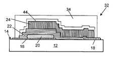
- the thin film battery 10includes a support substrate 12 having a support surface 14 , a cathode current collector 16 attached to the support surface 14 of the substrate 12 , and an anode current collector 18 on the support surface 14 of the substrate in a spaced-apart location relative to the cathode current collector 16 .
- a cathode 20is deposited on a portion of the cathode current collector 18 .
- a solid electrolyte 22is deposited over the cathode 20 , on a portion of the support surface 14 of the substrate 12 and on a portion of the anode current collector 18 .
- an anode 24is deposited on the electrolyte 22 and a portion of the anode current collector 18 .
- the components of the thin film batteryare referred to herein as the thin film battery stack 26 .
- the thin film battery stack 26has a maximum thickness of less than about 15 microns measured from the support surface 14 to the highest point of the battery stack 26 above the support surface 14 .
- the battery stack 26is relatively non-planar. That is, there is a “stair-step” configuration of the upper surface 30 , caused by overlapping the layers of the thin film battery 10 . Accordingly, the conformal coating 28 applied to the battery stack 26 also provides a non-planar upper surface 30 of the battery.
- One such conformal coatingis described, for example, in U.S. Pat. No. 5,561,004 to Bates et al. Experiments have shown that a coating 28 consisting of alternating layers of parylene and metal films provides protection for no longer than about three months even though the total thickness of the multilayer coating ranges from about 5 to about 10 ⁇ m. During this period of time, sufficient oxygen and water diffuse through the coating 28 so that essentially all of the lithium in a lithium anode 24 is converted to lithium oxide and/or lithium hydroxide.
- parylene-metal multilayer coating 28It is believed that the failure of a parylene-metal multilayer coating 28 is due to the conformal nature of parylene and to the presence of pin holes in the coating 28 . Asperities or pits on the surface of the anode 24 are replicated by a first parylene layer, so that a following metal layer does not uniformly coat the surface of the parylene. Since the metal films are deposited by sputtering or evaporation which are line of sight processes, the asperities shadow regions of the anode 24 from the metal coating, and possibly some regions near asperities receive little or no metal coating at all. Parylene by itself provides little protection because the transmission rates of oxygen and water through this material are too high to protect the anode from oxygen and/or water or water vapor.
- the present inventionsolves the problem of pin holes and asperities by first “planarizing” the battery surface 30 with a polymeric film that forms a planarization layer over the thin film battery stack 26 .
- the planarization layeris formed by flash evaporating a monomer or oligomer such as a high molecular weight acrylate and then polymerizing the monomer film by cross linking using ultra violet (UV) or electron beam (EB) irradiation.
- UVultra violet
- EBelectron beam
- the planarization layeris combined with additional barrier layer materials selected from metal, ceramic, and/or polymeric materials to provide a composite planarization/barrier layer 34 as illustrated in FIG. 2 .
- the monomer or oligomer deposit providing the planarization layerspreads out evenly over the surface of the battery and substrate to a depth that completely covers the asperities and other rough surface features. After cross-linking, a smooth, flat layer remains so that subsequent layers of metal or ceramic films are deposited onto a smooth, flat surface. This avoids any shadowing effects and minimizes the formation of pin holes during the deposition processes.
- the planarization layercan be deposited by spray or dip coating as described generally in U.S. Pat. No. 5,725,909 to Shaw et al., the disclosure of which is incorporated by reference thereto as if fully set forth herein, or by spin coating a monomer or oligomer followed by a UV cure.
- An important feature of the inventionis the provision of a planarizing layer followed by one or more additional barrier layers to provide a relatively smooth and substantially planar planarization layer/barrier layer composite 34 that is substantially pin hole free.
- a relatively smooth composite layer 34preferably has a surface roughness of no more than about 1.0 nanometers (nm) root mean square (RMS), and preferably from about 0.1 to about 1.0 nm RMS.
- a substantially planar composite 34preferably has a flatness of no greater than 0.005 cm/inch. In other words, for each inch of travel across the surface of the composite 34 , the deviation in height of the surface of the composite 34 is no more than about 0.005 centimeters.
- the preferred monomersare polyfunctional acrylates with number average molecular weights ranging from about 150 to about 1000 MW N , preferably ranging from about 200 to about 300 MW N .
- Such monomersare set forth, for example in U.S. Pat. No. 4,842,893 to Yializis, et al.
- acrylate monomers and oligomersthat may be used in accordance with the invention for providing a relatively smooth, and substantially planar planarization layer.
- the preferred monomersare hydrophobic and substantially non-reactive with the anode material of the thin film battery.
- Particularly preferred monomersare polyfunctional acrylates with number average molecular weights ranging from about 150 to about 5000 MW N , preferably ranging from about 200 to about 300 MW N .
- Such monomersare set forth, for example in U.S. Pat. No. 4,842,893 to Yializis, et al. and U.S. Pat. No. 4,499,520 to Cichanowski.
- any of the monomer or oligomer acrylates, diacrylates, or triacrylates that do not contain an acid group, i.e.—COOH,are suitable for providing the planarization layer.
- Other polymeric materialsmay also be used for the planarization layer.
- film forming polyolefins, such as polyethylene and polypropylene monomers deposited by plasma polymerizationmay also be used.
- hydrophobic oligomerssuch as polybutadiene dimethacrylate and polybutadiene urethane diacrylate are preferred because of their chemical and water resistance.
- the foregoing oligomersmay also be vapor deposited as well and cross-linked using UV radiation or EB curing.
- any number of different combinations of ceramic, metal, and additional polymeric layersmay be deposited on the relatively smooth planarization layer in order to provide a barrier layer for protecting the thin film battery.
- ceramic and metal films suitable for providing the one or more barrier layersis provided, for example, in U.S. Pat. No. 6,413,645 to Graff et al., the disclosure of which is incorporated by reference as if fully set forth herein.
- Planarization and barrier layer composites for thin film batteriesare illustrated for, example, in FIGS. 3–5 .
- a composite planarization layer/barrier layer 34 for a thin film battery 32is provided.
- the planarization layer 36is provided by a monomer or oligomer as described above.
- the thickness of the planarization layer 36preferably ranges from about 1 to about 5 microns.
- a metal layer 38 , ceramic layer 40 , and/or polymeric layer 42is applied to the planarization layer 36 to provide one or more barrier layers.
- the thickness of each of the one or more barrier layers 38 , 40 , and 42preferably ranges from about 20 nanometers to about 1 micron.
- Ceramic materials useful for forming a ceramic barrier layerinclude, but are not limited to, metal oxides, metal nitrides, metal carbides, metal oxynitrides, and the like, such as Al 2 O 3 , AIN, In 2 O 3 , SiO 2 , Si 3 N 4 , SiC, silicon oxynitride, SnO 2 , indium tin oxide, TiO 2 and ZrO 2 .
- Metal materials useful for forming a metal barrier layerinclude, but are not limited to, Al, Ta, Ti, and W.
- Polymeric materials useful for forming a polymeric barrier layerinclude, but are not limited to, the materials used for providing the planarization layer 36 .
- the planarization layer 36may be deposited directly on the anode layer 24 ( FIG. 3 ).
- a metal layer 38is deposited on the planarization layer 36 .
- a ceramic layer 40is deposited on the metal layer, and a polymeric layer 42 is deposited on the ceramic layer. If desired, additional ceramic, metal, and/or polymeric layers may be deposited on the polymeric layer 42 to provide the composite planarization layer/barrier layer on the thin film battery.
- the order, selection, and number of barrier layer materials deposited on the planarization layer 36is not critical to the invention, provided a relatively smooth planarization layer 36 , as set forth above, is provided over the thin film battery stack.
- a copper or other metal that does not alloy to any significant extent with the anode layer 24such as V, Cr, Ni, Ti, or W is deposited as a protective layer 44 over the anode layer and a portion of the anode current collector 18 .
- the protective layer 44provides temporary protection for the anode 24 and also improves the electrical contact between the anode 24 and the anode current collector 18 .
- the planarization layer 36is deposited on the protective layer 44 next followed by alternating layers of metal, layer 38 , and/or ceramic, layer 40 , and/or polymer, layer 42 .
- a layer 46 of the electrolyte materialfor example, lithium phosphorus oxynitride (“LIPON”)
- LIPONlithium phosphorus oxynitride
- a sacrificial or getter layer 48 of magnesiummay also is deposited in a barrier layer stack 50 close to the planarization layer 36 in order to trap oxygen or water that has diffused through the barrier layer stack 50 .
- the thickness of the getter layer 48preferably ranges from about 10 nm to about 100 nm. Magnesium will react with O 2 to form MgO or with O 2 and H 2 O to form Mg(OH) 2 .
- Various composite planarization layer/barrier layer composites according to the inventionmay include, but are not limited to:
- barrier coating materials for light emitting diodesOLEDs
- dielectric constant of the dielectric layeris of concern
- the barrier layersmust be transparent.
- the barrier coating materials selected for thin film battery barrier layersserve only to limit the amount of oxygen and/or water vapor that reaches the anode and other battery components, and therefore the dielectric or optical properties of the barrier coating films are unimportant.
- FIGS. 6–7Schematic diagrams of an apparatus 60 for applying the planarization layer 36 , barrier layers 38 , 40 , and 42 , and getter layer coating materials to a thin film battery are illustrated in FIGS. 6–7 .
- FIG. 6is a schematic side view of the apparatus 60
- FIG. 7is a schematic top plan view of the apparatus 60 .
- the vacuum deposition chamber 62 for depositing the anode layer, planarization or polymer layer chamber 64 , and metal and/or ceramic layers chamber 66 and 68are isolated from one another by gate valves 70 , 72 , and 74 so that each chamber can be isolated from adjacent chamber(s).
- This arrangement of vacuum chambers 62 , 64 , 66 , and 68 and gate valves 70 , 72 , and 74is referred to as an in-line deposition system.
- the thin film batteryis transferred into the polymer coating chamber 64 for depositing the planarization layer 36 on the anode 24 .
- the planarization layer 36is preferably deposited by flash evaporation of a monomer or oligomer followed by a UV or EB cure to polymerize the film. If the anodes 24 are deposited in separate system, they are placed in an anode load chamber 76 for transfer into the polymer coating chamber 64 .
- the batteryAfter depositing and curing the planarization layer 36 in chamber 64 , the battery is moved into chamber 66 for deposition of a metal layer 38 or ceramic layer 40 and then into chamber 68 for depositing a second metal layer 38 or ceramic layer 40 .
- Each of the metal or ceramic layersare preferably deposited by sputtering, evaporation, or plasma enhanced chemical vapor deposition.
- the arrowsindicate that the battery may be moved back and forth through chamber 64 and the two metal and/or ceramic coating chambers 66 and 68 as many times as necessary to obtain a multilayer coating with the desired barrier properties.
- the planarization layer 36can be applied by spin coating, dip coating, or spraying in chamber 78 followed by UV cure.
- the battery with the planarization layer 36is then loaded from chamber 78 into the metal/ceramic coating chambers 66 and 68 for applying one or more ceramic and/or metal layers to the planarization layer 36 .
- a particularly preferred doped electrolyte for a lithium or lithium ion batteryincorporates a sulfide ion.
- compositions of the foregoing formulapreferably contain from about 37.4 to about 39.7 atomic percent lithium ion, from about 11.8 to about 13.1 atomic percent phosphorus ion and from about 41.7 to about 45.4 atomic percent oxygen ion in addition to the sulfide ion and nitrogen ion.
- electrolyte compositions of the inventionhaving the preferred S/P ratios are given in the following table:
- Electrolytes of the foregoing compositionmay be used in thin-film batteries having oxide-based cathodes, such as LiCoO 2 and LiMn 2 O 4 , that operate at potentials above 3.8 volts.
Landscapes
- Chemical & Material Sciences (AREA)
- Chemical Kinetics & Catalysis (AREA)
- Electrochemistry (AREA)
- General Chemical & Material Sciences (AREA)
- Engineering & Computer Science (AREA)
- Inorganic Chemistry (AREA)
- Manufacturing & Machinery (AREA)
- Composite Materials (AREA)
- Materials Engineering (AREA)
- Secondary Cells (AREA)
Abstract
Description
2Li+H2O+½O2=2LiOH (I)
2Li+½O2=Li2O (II)
- P/C/M/PL/anode;
- P/M/C/PL/Cu/anode;
- P/C/M/C/Mg/PL/Cu/anode;
- P/M/C/Mg/PL/LIPON/Cu/anode
wherein P is a polymeric material, M is a metal material, C is a ceramic material, and PL is a planarization layer.
LiwPOxNySz
where 2x+3y+2z=5+w, x ranges from about 3.2 to about 3.8, y ranges from about 0.13 to about 0.46, z ranges from greater than zero up to about 0.2, and w ranges from about 2.9 to about 3.3. Compositions of the foregoing formula, preferably contain from about 37.4 to about 39.7 atomic percent lithium ion, from about 11.8 to about 13.1 atomic percent phosphorus ion and from about 41.7 to about 45.4 atomic percent oxygen ion in addition to the sulfide ion and nitrogen ion. Examples of electrolyte compositions of the invention having the preferred S/P ratios are given in the following table:
| Li ion | P ion | Oxygen ion | Nitrogen ion | Sulfide ion |
| (atomic %) | (atomic %) | (atomic %) | (atomic %) | (atomic %) |
| 39.43 | 11.95 | 45.40 | 2.03 | 1.19 |
| 39.66 | 12.02 | 44.47 | 2.64 | 1.20 |
| 37.81 | 13.04 | 43.02 | 4.82 | 1.30 |
| 37.86 | 13.05 | 41.78 | 6.01 | 1.31 |
| 39.36 | 11.93 | 45.33 | 1.59 | 1.79 |
| 37.74 | 13.02 | 42.95 | 4.34 | 1.95 |
| 38.94 | 11.80 | 44.90 | 2.60 | 1.77 |
| 37.40 | 12.89 | 41.84 | 5.93 | 1.93 |
Electrolytes of the foregoing composition may be used in thin-film batteries having oxide-based cathodes, such as LiCoO2and LiMn2O4, that operate at potentials above 3.8 volts.
Claims (21)
LiwPOxNySz,
Priority Applications (1)
| Application Number | Priority Date | Filing Date | Title |
|---|---|---|---|
| US10/244,260US6994933B1 (en) | 2002-09-16 | 2002-09-16 | Long life thin film battery and method therefor |
Applications Claiming Priority (1)
| Application Number | Priority Date | Filing Date | Title |
|---|---|---|---|
| US10/244,260US6994933B1 (en) | 2002-09-16 | 2002-09-16 | Long life thin film battery and method therefor |
Publications (1)
| Publication Number | Publication Date |
|---|---|
| US6994933B1true US6994933B1 (en) | 2006-02-07 |
Family
ID=35734177
Family Applications (1)
| Application Number | Title | Priority Date | Filing Date |
|---|---|---|---|
| US10/244,260Expired - Fee RelatedUS6994933B1 (en) | 2002-09-16 | 2002-09-16 | Long life thin film battery and method therefor |
Country Status (1)
| Country | Link |
|---|---|
| US (1) | US6994933B1 (en) |
Cited By (73)
| Publication number | Priority date | Publication date | Assignee | Title |
|---|---|---|---|---|
| US20040172090A1 (en)* | 2002-12-09 | 2004-09-02 | Janzig Darren A. | Coupling module of a modular implantable medical device |
| US20050004618A1 (en)* | 2003-05-16 | 2005-01-06 | Scott Erik R. | Implantable medical device with a nonhermetic battery |
| US20050003268A1 (en)* | 2003-05-16 | 2005-01-06 | Scott Erik R. | Battery housing configuration |
| US20050176181A1 (en)* | 1999-10-25 | 2005-08-11 | Burrows Paul E. | Method for edge sealing barrier films |
| US20050239294A1 (en)* | 2002-04-15 | 2005-10-27 | Rosenblum Martin P | Apparatus for depositing a multilayer coating on discrete sheets |
| US20060106451A1 (en)* | 2004-11-18 | 2006-05-18 | Yuri Busiashvili | Electronic anti-coagulation stent for intra-arterial deployment |
| US20060267167A1 (en)* | 2004-10-25 | 2006-11-30 | Mccain Joseph H | Microelectronic device with integrated energy source |
| US20060286448A1 (en)* | 2002-08-09 | 2006-12-21 | Snyder Shawn W | Electrochemical apparatus with barrier layer protected substrate |
| US20070040195A1 (en)* | 2005-08-19 | 2007-02-22 | The University Of Chicago | Monolithic integrated passive and active electronic devices with biocompatible coatings |
| US20070066932A1 (en)* | 2005-09-15 | 2007-03-22 | Transcutaneous Technologies Inc. | Iontophoresis device |
| US20070078445A1 (en)* | 2005-09-30 | 2007-04-05 | Curt Malloy | Synchronization apparatus and method for iontophoresis device to deliver active agents to biological interfaces |
| US20070078376A1 (en)* | 2005-09-30 | 2007-04-05 | Smith Gregory A | Functionalized microneedles transdermal drug delivery systems, devices, and methods |
| US20070074732A1 (en)* | 2004-04-30 | 2007-04-05 | Medtronic, Inc. | Implantable medical device with lubricious material |
| US20070164376A1 (en)* | 1999-10-25 | 2007-07-19 | Burrows Paul E | Method for edge sealing barrier films |
| US20070213652A1 (en)* | 2005-12-30 | 2007-09-13 | Transcutaneous Technologies Inc. | System and method for remote based control of an iontophoresis device |
| US20070255338A1 (en)* | 2006-04-28 | 2007-11-01 | Medtronic, Inc. | Cranial implant |
| US20070264564A1 (en)* | 2006-03-16 | 2007-11-15 | Infinite Power Solutions, Inc. | Thin film battery on an integrated circuit or circuit board and method thereof |
| US20080003493A1 (en)* | 2005-09-06 | 2008-01-03 | Bates John B | Getters for thin film battery hermetic package |
| US20080065173A1 (en)* | 2003-05-16 | 2008-03-13 | Medtronic, Inc. | Headset recharger for cranially implantable medical devices |
| US20080114282A1 (en)* | 2006-09-05 | 2008-05-15 | Transcu Ltd. | Transdermal drug delivery systems, devices, and methods using inductive power supplies |
| WO2008070524A3 (en)* | 2006-12-01 | 2008-10-02 | Tti Ellebeau Inc Shinkan Build | Systems, devices, and methods for powering and/or controlling devices, for instance transdermal delivery devices |
| USRE40531E1 (en) | 1999-10-25 | 2008-10-07 | Battelle Memorial Institute | Ultrabarrier substrates |
| US20080261107A1 (en)* | 2002-08-09 | 2008-10-23 | Snyder Shawn W | Robust metal film encapsulation |
| US7510913B2 (en) | 2003-04-11 | 2009-03-31 | Vitex Systems, Inc. | Method of making an encapsulated plasma sensitive device |
| USRE40787E1 (en) | 1999-10-25 | 2009-06-23 | Battelle Memorial Institute | Multilayer plastic substrates |
| US20090292327A1 (en)* | 2002-12-09 | 2009-11-26 | Medtronic, Inc. | Implantable medical device with anti-infection agent |
| US20090288943A1 (en)* | 2008-05-21 | 2009-11-26 | Byung Sung Kwak | Thin film batteries and methods for manufacturing same |
| US20090299380A1 (en)* | 2004-04-29 | 2009-12-03 | Medtronic, Inc. | Implantation of implantable medical device |
| US7648925B2 (en) | 2003-04-11 | 2010-01-19 | Vitex Systems, Inc. | Multilayer barrier stacks and methods of making multilayer barrier stacks |
| US20100068617A1 (en)* | 2008-09-16 | 2010-03-18 | Commissariat A L'energie Atomique | Lithium microbattery comprising an encapsulating layer and fabrication method |
| US20100190051A1 (en)* | 2009-01-29 | 2010-07-29 | Bruce Gardiner Aitken | Barrier layer for thin film battery |
| US7767498B2 (en) | 2005-08-25 | 2010-08-03 | Vitex Systems, Inc. | Encapsulated devices and method of making |
| US20100239907A1 (en)* | 2009-03-20 | 2010-09-23 | Semiconductor Energy Laboratory Co., Ltd. | Power Storage Device and Manufacturing Method Thereof |
| CN101911367A (en)* | 2008-01-11 | 2010-12-08 | 无穷动力解决方案股份有限公司 | Thin film encapsulation for thin film batteries and other devices |
| US20100330748A1 (en)* | 1999-10-25 | 2010-12-30 | Xi Chu | Method of encapsulating an environmentally sensitive device |
| US20110097625A1 (en)* | 2009-10-26 | 2011-04-28 | Commissariat A L'energie Atomique Et Aux Energies Alternatives | Lithium microbattery provided with an electronically conductive packaging layer |
| US20110129594A1 (en)* | 2009-09-22 | 2011-06-02 | Byung-Sung Kwak | Thin-film battery methods for complexity reduction |
| US7959769B2 (en) | 2004-12-08 | 2011-06-14 | Infinite Power Solutions, Inc. | Deposition of LiCoO2 |
| US7993773B2 (en) | 2002-08-09 | 2011-08-09 | Infinite Power Solutions, Inc. | Electrochemical apparatus with barrier layer protected substrate |
| US8003244B2 (en) | 2003-10-06 | 2011-08-23 | Fraunhofer-Gesellschaft zur Föerderung der Angewandten Forschung E.V. | Battery, especially a microbattery, and the production thereof using wafer-level technology |
| US8062708B2 (en) | 2006-09-29 | 2011-11-22 | Infinite Power Solutions, Inc. | Masking of and material constraint for depositing battery layers on flexible substrates |
| US8197781B2 (en) | 2006-11-07 | 2012-06-12 | Infinite Power Solutions, Inc. | Sputtering target of Li3PO4 and method for producing same |
| US8236443B2 (en) | 2002-08-09 | 2012-08-07 | Infinite Power Solutions, Inc. | Metal film encapsulation |
| US20120214047A1 (en)* | 2007-10-25 | 2012-08-23 | Motorola Mobility, Inc. | Method for high volume manufacturing of thin film batteries |
| US8260203B2 (en) | 2008-09-12 | 2012-09-04 | Infinite Power Solutions, Inc. | Energy device with integral conductive surface for data communication via electromagnetic energy and method thereof |
| US8268488B2 (en) | 2007-12-21 | 2012-09-18 | Infinite Power Solutions, Inc. | Thin film electrolyte for thin film batteries |
| US8350519B2 (en) | 2008-04-02 | 2013-01-08 | Infinite Power Solutions, Inc | Passive over/under voltage control and protection for energy storage devices associated with energy harvesting |
| US8404376B2 (en) | 2002-08-09 | 2013-03-26 | Infinite Power Solutions, Inc. | Metal film encapsulation |
| US8431264B2 (en) | 2002-08-09 | 2013-04-30 | Infinite Power Solutions, Inc. | Hybrid thin-film battery |
| US8445130B2 (en) | 2002-08-09 | 2013-05-21 | Infinite Power Solutions, Inc. | Hybrid thin-film battery |
| WO2013102269A1 (en)* | 2012-01-05 | 2013-07-11 | Electrovaya Inc. | Thin film electrochemical cell with a polymer double seal |
| US8508193B2 (en) | 2008-10-08 | 2013-08-13 | Infinite Power Solutions, Inc. | Environmentally-powered wireless sensor module |
| US8599572B2 (en) | 2009-09-01 | 2013-12-03 | Infinite Power Solutions, Inc. | Printed circuit board with integrated thin film battery |
| US8636876B2 (en) | 2004-12-08 | 2014-01-28 | R. Ernest Demaray | Deposition of LiCoO2 |
| CN103636025A (en)* | 2011-06-17 | 2014-03-12 | 应用材料公司 | Maskless Manufacturing of Thin Film Batteries |
| US8728285B2 (en) | 2003-05-23 | 2014-05-20 | Demaray, Llc | Transparent conductive oxides |
| US8815450B1 (en) | 2008-01-28 | 2014-08-26 | Oak Ridge Micro-Energy, Inc. | Low voltage thin film batteries |
| US8900743B2 (en) | 2011-10-27 | 2014-12-02 | Sakti3, Inc. | Barrier for thin film lithium batteries made on flexible substrates and related methods |
| US8906523B2 (en) | 2008-08-11 | 2014-12-09 | Infinite Power Solutions, Inc. | Energy device with integral collector surface for electromagnetic energy harvesting and method thereof |
| US9334557B2 (en) | 2007-12-21 | 2016-05-10 | Sapurast Research Llc | Method for sputter targets for electrolyte films |
| US9393432B2 (en) | 2008-10-31 | 2016-07-19 | Medtronic, Inc. | Non-hermetic direct current interconnect |
| WO2017121891A1 (en)* | 2016-01-15 | 2017-07-20 | Saralon Gmbh | Thin battery and manufacturing method therefore |
| US9761847B2 (en) | 2013-01-31 | 2017-09-12 | Sakti3, Inc. | Packaging and termination structure for a solid state battery |
| US9839940B2 (en) | 2002-04-15 | 2017-12-12 | Samsung Display Co., Ltd. | Apparatus for depositing a multilayer coating on discrete sheets |
| WO2017180967A3 (en)* | 2016-04-14 | 2018-07-26 | Applied Materials, Inc. | Multilayer thin film device encapsulation using soft and pliable layer first |
| WO2017180971A3 (en)* | 2016-04-14 | 2018-07-26 | Applied Materials, Inc. | Multilayer thin film device encapsulation using soft and pliable layer first |
| US20180323430A1 (en)* | 2016-07-21 | 2018-11-08 | Lg Chem, Ltd. | Lithium secondary battery comprising positive electrode active material for synthesis of lithium cobalt oxide and preparation method thereof |
| WO2019053405A1 (en) | 2017-09-15 | 2019-03-21 | Dyson Technology Limited | Continuous manufacturing of stacked electrochemical device with polymer interlayer |
| WO2019133702A1 (en)* | 2017-12-29 | 2019-07-04 | Staq Energy, Inc. | Long life sealed alkaline secondary batteries |
| US10680277B2 (en) | 2010-06-07 | 2020-06-09 | Sapurast Research Llc | Rechargeable, high-density electrochemical device |
| US12294086B2 (en) | 2019-07-26 | 2025-05-06 | Form Energy, Inc. | Low cost metal electrodes |
| US12362352B2 (en) | 2018-07-27 | 2025-07-15 | Form Energy, Inc. | Negative electrodes for electrochemical cells |
| US12444755B2 (en) | 2024-02-08 | 2025-10-14 | Form Energy, Inc. | Corrugated fuel electrode |
Citations (21)
| Publication number | Priority date | Publication date | Assignee | Title |
|---|---|---|---|---|
| JPS59226472A (en) | 1983-06-06 | 1984-12-19 | Hitachi Ltd | Thin film lithium battery |
| US4499520A (en) | 1983-12-19 | 1985-02-12 | General Electric Company | Capacitor with dielectric comprising poly-functional acrylate polymer and method of making |
| US4586111A (en) | 1984-08-01 | 1986-04-29 | Sfe Technologies | Capacitor with dielectric comprising a polymer of polyacrylate polyether pre-polymer |
| US4842893A (en) | 1983-12-19 | 1989-06-27 | Spectrum Control, Inc. | High speed process for coating substrates |
| US4954371A (en) | 1986-06-23 | 1990-09-04 | Spectrum Control, Inc. | Flash evaporation of monomer fluids |
| US5260095A (en) | 1992-08-21 | 1993-11-09 | Battelle Memorial Institute | Vacuum deposition and curing of liquid monomers |
| US5338625A (en) | 1992-07-29 | 1994-08-16 | Martin Marietta Energy Systems, Inc. | Thin film battery and method for making same |
| US5440446A (en) | 1993-10-04 | 1995-08-08 | Catalina Coatings, Inc. | Acrylate coating material |
| US5561004A (en) | 1994-02-25 | 1996-10-01 | Bates; John B. | Packaging material for thin film lithium batteries |
| US5612152A (en) | 1994-01-12 | 1997-03-18 | Martin Marietta Energy Systems, Inc. | Rechargeable lithium battery for use in applications requiring a low to high power output |
| US5725909A (en) | 1993-10-04 | 1998-03-10 | Catalina Coatings, Inc. | Acrylate composite barrier coating process |
| US6146225A (en) | 1998-07-30 | 2000-11-14 | Agilent Technologies, Inc. | Transparent, flexible permeability barrier for organic electroluminescent devices |
| US6168884B1 (en) | 1999-04-02 | 2001-01-02 | Lockheed Martin Energy Research Corporation | Battery with an in-situ activation plated lithium anode |
| US6242132B1 (en) | 1997-04-16 | 2001-06-05 | Ut-Battelle, Llc | Silicon-tin oxynitride glassy composition and use as anode for lithium-ion battery |
| US6268695B1 (en) | 1998-12-16 | 2001-07-31 | Battelle Memorial Institute | Environmental barrier material for organic light emitting device and method of making |
| US6270841B1 (en) | 1999-07-02 | 2001-08-07 | Sigma Technologies International, Inc. | Thin coating manufactured by vapor deposition of solid oligomers |
| US6365300B1 (en) | 1998-12-03 | 2002-04-02 | Sumitomo Electric Industries, Ltd. | Lithium secondary battery |
| US6387563B1 (en) | 2000-03-28 | 2002-05-14 | Johnson Research & Development, Inc. | Method of producing a thin film battery having a protective packaging |
| US20020071989A1 (en) | 2000-12-08 | 2002-06-13 | Verma Surrenda K. | Packaging systems and methods for thin film solid state batteries |
| US6413645B1 (en)* | 2000-04-20 | 2002-07-02 | Battelle Memorial Institute | Ultrabarrier substrates |
| US6413285B1 (en) | 1999-11-01 | 2002-07-02 | Polyplus Battery Company | Layered arrangements of lithium electrodes |
- 2002
- 2002-09-16USUS10/244,260patent/US6994933B1/ennot_activeExpired - Fee Related
Patent Citations (24)
| Publication number | Priority date | Publication date | Assignee | Title |
|---|---|---|---|---|
| JPS59226472A (en) | 1983-06-06 | 1984-12-19 | Hitachi Ltd | Thin film lithium battery |
| US4499520A (en) | 1983-12-19 | 1985-02-12 | General Electric Company | Capacitor with dielectric comprising poly-functional acrylate polymer and method of making |
| US4842893A (en) | 1983-12-19 | 1989-06-27 | Spectrum Control, Inc. | High speed process for coating substrates |
| US4586111A (en) | 1984-08-01 | 1986-04-29 | Sfe Technologies | Capacitor with dielectric comprising a polymer of polyacrylate polyether pre-polymer |
| US4954371A (en) | 1986-06-23 | 1990-09-04 | Spectrum Control, Inc. | Flash evaporation of monomer fluids |
| US5338625A (en) | 1992-07-29 | 1994-08-16 | Martin Marietta Energy Systems, Inc. | Thin film battery and method for making same |
| US5512147A (en) | 1992-07-29 | 1996-04-30 | Martin Marietta Energy Systems, Inc. | Method of making an electrolyte for an electrochemical cell |
| US5567210A (en) | 1992-07-29 | 1996-10-22 | Martin Marietta Energy Systems, Inc. | Method for making an electrochemical cell |
| US5597660A (en) | 1992-07-29 | 1997-01-28 | Martin Marietta Energy Systems, Inc. | Electrolyte for an electrochemical cell |
| US5260095A (en) | 1992-08-21 | 1993-11-09 | Battelle Memorial Institute | Vacuum deposition and curing of liquid monomers |
| US5440446A (en) | 1993-10-04 | 1995-08-08 | Catalina Coatings, Inc. | Acrylate coating material |
| US5725909A (en) | 1993-10-04 | 1998-03-10 | Catalina Coatings, Inc. | Acrylate composite barrier coating process |
| US5612152A (en) | 1994-01-12 | 1997-03-18 | Martin Marietta Energy Systems, Inc. | Rechargeable lithium battery for use in applications requiring a low to high power output |
| US5561004A (en) | 1994-02-25 | 1996-10-01 | Bates; John B. | Packaging material for thin film lithium batteries |
| US6242132B1 (en) | 1997-04-16 | 2001-06-05 | Ut-Battelle, Llc | Silicon-tin oxynitride glassy composition and use as anode for lithium-ion battery |
| US6146225A (en) | 1998-07-30 | 2000-11-14 | Agilent Technologies, Inc. | Transparent, flexible permeability barrier for organic electroluminescent devices |
| US6365300B1 (en) | 1998-12-03 | 2002-04-02 | Sumitomo Electric Industries, Ltd. | Lithium secondary battery |
| US6268695B1 (en) | 1998-12-16 | 2001-07-31 | Battelle Memorial Institute | Environmental barrier material for organic light emitting device and method of making |
| US6168884B1 (en) | 1999-04-02 | 2001-01-02 | Lockheed Martin Energy Research Corporation | Battery with an in-situ activation plated lithium anode |
| US6270841B1 (en) | 1999-07-02 | 2001-08-07 | Sigma Technologies International, Inc. | Thin coating manufactured by vapor deposition of solid oligomers |
| US6413285B1 (en) | 1999-11-01 | 2002-07-02 | Polyplus Battery Company | Layered arrangements of lithium electrodes |
| US6387563B1 (en) | 2000-03-28 | 2002-05-14 | Johnson Research & Development, Inc. | Method of producing a thin film battery having a protective packaging |
| US6413645B1 (en)* | 2000-04-20 | 2002-07-02 | Battelle Memorial Institute | Ultrabarrier substrates |
| US20020071989A1 (en) | 2000-12-08 | 2002-06-13 | Verma Surrenda K. | Packaging systems and methods for thin film solid state batteries |
Non-Patent Citations (3)
| Title |
|---|
| G. Nisato, P.C.P. et al. Evaluating High Performance Diffusion Barriers, The Calcium Test International Display Workshop, Oct. 2001. |
| J.D. Affinito et al. Polymer-Oxide Transparent Barrier Layers 1996 Society of Vacuum Coaters, 39th Annual Technical Conference Proceedings, Pacific Northwest national Laboratory, Richland, WA pp. 392-397. |
| John B. Bates et al. "Thin-Film Lithium Batteries" in New Trends in Electrochemical Technology: Energy Storage Systems in Electronics, edited by T. Osaha and M. Datta, Gordon and Breach, 2000 pp. 453-485. |
Cited By (141)
| Publication number | Priority date | Publication date | Assignee | Title |
|---|---|---|---|---|
| US20070164376A1 (en)* | 1999-10-25 | 2007-07-19 | Burrows Paul E | Method for edge sealing barrier films |
| US20100330748A1 (en)* | 1999-10-25 | 2010-12-30 | Xi Chu | Method of encapsulating an environmentally sensitive device |
| USRE40787E1 (en) | 1999-10-25 | 2009-06-23 | Battelle Memorial Institute | Multilayer plastic substrates |
| US20050176181A1 (en)* | 1999-10-25 | 2005-08-11 | Burrows Paul E. | Method for edge sealing barrier films |
| USRE40531E1 (en) | 1999-10-25 | 2008-10-07 | Battelle Memorial Institute | Ultrabarrier substrates |
| US7727601B2 (en) | 1999-10-25 | 2010-06-01 | Vitex Systems, Inc. | Method for edge sealing barrier films |
| US20070210459A1 (en)* | 1999-10-25 | 2007-09-13 | Burrows Paul E | Method for edge sealing barrier films |
| US8900366B2 (en) | 2002-04-15 | 2014-12-02 | Samsung Display Co., Ltd. | Apparatus for depositing a multilayer coating on discrete sheets |
| US20050239294A1 (en)* | 2002-04-15 | 2005-10-27 | Rosenblum Martin P | Apparatus for depositing a multilayer coating on discrete sheets |
| US9839940B2 (en) | 2002-04-15 | 2017-12-12 | Samsung Display Co., Ltd. | Apparatus for depositing a multilayer coating on discrete sheets |
| US20060286448A1 (en)* | 2002-08-09 | 2006-12-21 | Snyder Shawn W | Electrochemical apparatus with barrier layer protected substrate |
| US7993773B2 (en) | 2002-08-09 | 2011-08-09 | Infinite Power Solutions, Inc. | Electrochemical apparatus with barrier layer protected substrate |
| US8535396B2 (en) | 2002-08-09 | 2013-09-17 | Infinite Power Solutions, Inc. | Electrochemical apparatus with barrier layer protected substrate |
| US8236443B2 (en) | 2002-08-09 | 2012-08-07 | Infinite Power Solutions, Inc. | Metal film encapsulation |
| US8445130B2 (en) | 2002-08-09 | 2013-05-21 | Infinite Power Solutions, Inc. | Hybrid thin-film battery |
| US9634296B2 (en) | 2002-08-09 | 2017-04-25 | Sapurast Research Llc | Thin film battery on an integrated circuit or circuit board and method thereof |
| US8431264B2 (en) | 2002-08-09 | 2013-04-30 | Infinite Power Solutions, Inc. | Hybrid thin-film battery |
| US9793523B2 (en) | 2002-08-09 | 2017-10-17 | Sapurast Research Llc | Electrochemical apparatus with barrier layer protected substrate |
| US20080261107A1 (en)* | 2002-08-09 | 2008-10-23 | Snyder Shawn W | Robust metal film encapsulation |
| US8021778B2 (en) | 2002-08-09 | 2011-09-20 | Infinite Power Solutions, Inc. | Electrochemical apparatus with barrier layer protected substrate |
| US8394522B2 (en) | 2002-08-09 | 2013-03-12 | Infinite Power Solutions, Inc. | Robust metal film encapsulation |
| US8404376B2 (en) | 2002-08-09 | 2013-03-26 | Infinite Power Solutions, Inc. | Metal film encapsulation |
| US20040172090A1 (en)* | 2002-12-09 | 2004-09-02 | Janzig Darren A. | Coupling module of a modular implantable medical device |
| US8397732B2 (en) | 2002-12-09 | 2013-03-19 | Medtronic, Inc. | Implantation of low-profile implantable medical device |
| US8666497B2 (en) | 2002-12-09 | 2014-03-04 | Medtronic, Inc. | Coupling module of a modular implantable medical device |
| US7848817B2 (en) | 2002-12-09 | 2010-12-07 | Medtronic, Inc. | Coupling module of a modular implantable medical device |
| US20090292327A1 (en)* | 2002-12-09 | 2009-11-26 | Medtronic, Inc. | Implantable medical device with anti-infection agent |
| US8086313B2 (en) | 2002-12-09 | 2011-12-27 | Medtronic, Inc. | Implantable medical device with anti-infection agent |
| US7529586B2 (en) | 2002-12-09 | 2009-05-05 | Medtronic, Inc. | Concavity of an implantable medical device |
| US20070185539A1 (en)* | 2002-12-09 | 2007-08-09 | Medtronic, Inc. | Overmold for a modular implantable medical device |
| US20110054563A1 (en)* | 2002-12-09 | 2011-03-03 | Medtronic, Inc. | Coupling module of a modular implantable medical device |
| US20040176673A1 (en)* | 2002-12-09 | 2004-09-09 | Wahlstrand Carl D. | Concavity of an implantable medical device |
| US7648925B2 (en) | 2003-04-11 | 2010-01-19 | Vitex Systems, Inc. | Multilayer barrier stacks and methods of making multilayer barrier stacks |
| US7510913B2 (en) | 2003-04-11 | 2009-03-31 | Vitex Systems, Inc. | Method of making an encapsulated plasma sensitive device |
| US20080021511A1 (en)* | 2003-05-16 | 2008-01-24 | Medtronic, Inc. | Implantable medical device with a nonhermetic battery |
| US7881796B2 (en)* | 2003-05-16 | 2011-02-01 | Medtronic, Inc. | Implantable medical device with a nonhermetic battery |
| US20080065173A1 (en)* | 2003-05-16 | 2008-03-13 | Medtronic, Inc. | Headset recharger for cranially implantable medical devices |
| US7263401B2 (en)* | 2003-05-16 | 2007-08-28 | Medtronic, Inc. | Implantable medical device with a nonhermetic battery |
| US20050003268A1 (en)* | 2003-05-16 | 2005-01-06 | Scott Erik R. | Battery housing configuration |
| US20050004618A1 (en)* | 2003-05-16 | 2005-01-06 | Scott Erik R. | Implantable medical device with a nonhermetic battery |
| US8728285B2 (en) | 2003-05-23 | 2014-05-20 | Demaray, Llc | Transparent conductive oxides |
| US8003244B2 (en) | 2003-10-06 | 2011-08-23 | Fraunhofer-Gesellschaft zur Föerderung der Angewandten Forschung E.V. | Battery, especially a microbattery, and the production thereof using wafer-level technology |
| US9099410B2 (en) | 2003-10-13 | 2015-08-04 | Joseph H. McCain | Microelectronic device with integrated energy source |
| US9413405B2 (en) | 2003-10-13 | 2016-08-09 | Joseph H. McCain | Microelectronic device with integrated energy source |
| US20090299165A1 (en)* | 2004-04-29 | 2009-12-03 | Medronic, Inc. | Implantation of implantable medical device |
| US20090299380A1 (en)* | 2004-04-29 | 2009-12-03 | Medtronic, Inc. | Implantation of implantable medical device |
| US8280478B2 (en) | 2004-04-29 | 2012-10-02 | Medtronic, Inc. | Evaluation of implantation site for implantation of implantable medical device |
| US20090299164A1 (en)* | 2004-04-29 | 2009-12-03 | Medtronic, Inc. | Implantation of implantable medical device |
| US20070074732A1 (en)* | 2004-04-30 | 2007-04-05 | Medtronic, Inc. | Implantable medical device with lubricious material |
| US9162072B2 (en) | 2004-04-30 | 2015-10-20 | Medtronic, Inc. | Implantable medical device with lubricious material |
| US7557433B2 (en) | 2004-10-25 | 2009-07-07 | Mccain Joseph H | Microelectronic device with integrated energy source |
| US20060267167A1 (en)* | 2004-10-25 | 2006-11-30 | Mccain Joseph H | Microelectronic device with integrated energy source |
| US20060106451A1 (en)* | 2004-11-18 | 2006-05-18 | Yuri Busiashvili | Electronic anti-coagulation stent for intra-arterial deployment |
| US7959769B2 (en) | 2004-12-08 | 2011-06-14 | Infinite Power Solutions, Inc. | Deposition of LiCoO2 |
| US8636876B2 (en) | 2004-12-08 | 2014-01-28 | R. Ernest Demaray | Deposition of LiCoO2 |
| US20070040195A1 (en)* | 2005-08-19 | 2007-02-22 | The University Of Chicago | Monolithic integrated passive and active electronic devices with biocompatible coatings |
| US7767498B2 (en) | 2005-08-25 | 2010-08-03 | Vitex Systems, Inc. | Encapsulated devices and method of making |
| US7553582B2 (en)* | 2005-09-06 | 2009-06-30 | Oak Ridge Micro-Energy, Inc. | Getters for thin film battery hermetic package |
| US20080003493A1 (en)* | 2005-09-06 | 2008-01-03 | Bates John B | Getters for thin film battery hermetic package |
| US7890164B2 (en) | 2005-09-15 | 2011-02-15 | Tti Ellebeau, Inc. | Iontophoresis device |
| US20070066932A1 (en)* | 2005-09-15 | 2007-03-22 | Transcutaneous Technologies Inc. | Iontophoresis device |
| US20070078376A1 (en)* | 2005-09-30 | 2007-04-05 | Smith Gregory A | Functionalized microneedles transdermal drug delivery systems, devices, and methods |
| US20070078445A1 (en)* | 2005-09-30 | 2007-04-05 | Curt Malloy | Synchronization apparatus and method for iontophoresis device to deliver active agents to biological interfaces |
| US20070213652A1 (en)* | 2005-12-30 | 2007-09-13 | Transcutaneous Technologies Inc. | System and method for remote based control of an iontophoresis device |
| US20140030584A1 (en)* | 2006-03-16 | 2014-01-30 | Infinite Power Solutions, Inc. | Thin film battery on an integrated circuit or circuit board and method thereof |
| US20070264564A1 (en)* | 2006-03-16 | 2007-11-15 | Infinite Power Solutions, Inc. | Thin film battery on an integrated circuit or circuit board and method thereof |
| US20070255338A1 (en)* | 2006-04-28 | 2007-11-01 | Medtronic, Inc. | Cranial implant |
| US9084901B2 (en) | 2006-04-28 | 2015-07-21 | Medtronic, Inc. | Cranial implant |
| US9504402B2 (en) | 2006-04-28 | 2016-11-29 | Medtronic, Inc. | Cranial implant |
| US20080114282A1 (en)* | 2006-09-05 | 2008-05-15 | Transcu Ltd. | Transdermal drug delivery systems, devices, and methods using inductive power supplies |
| EP2070134A4 (en)* | 2006-09-20 | 2009-12-30 | Oak Ridge Micro Energy | Thin film battery hermetic package |
| WO2008036731A3 (en)* | 2006-09-20 | 2008-11-06 | Oak Ridge Micro Energy | Thin film battery hermetic package |
| US8062708B2 (en) | 2006-09-29 | 2011-11-22 | Infinite Power Solutions, Inc. | Masking of and material constraint for depositing battery layers on flexible substrates |
| US8197781B2 (en) | 2006-11-07 | 2012-06-12 | Infinite Power Solutions, Inc. | Sputtering target of Li3PO4 and method for producing same |
| WO2008070524A3 (en)* | 2006-12-01 | 2008-10-02 | Tti Ellebeau Inc Shinkan Build | Systems, devices, and methods for powering and/or controlling devices, for instance transdermal delivery devices |
| US8062783B2 (en) | 2006-12-01 | 2011-11-22 | Tti Ellebeau, Inc. | Systems, devices, and methods for powering and/or controlling devices, for instance transdermal delivery devices |
| US10950821B2 (en) | 2007-01-26 | 2021-03-16 | Samsung Display Co., Ltd. | Method of encapsulating an environmentally sensitive device |
| US20120214047A1 (en)* | 2007-10-25 | 2012-08-23 | Motorola Mobility, Inc. | Method for high volume manufacturing of thin film batteries |
| US9334557B2 (en) | 2007-12-21 | 2016-05-10 | Sapurast Research Llc | Method for sputter targets for electrolyte films |
| US8268488B2 (en) | 2007-12-21 | 2012-09-18 | Infinite Power Solutions, Inc. | Thin film electrolyte for thin film batteries |
| JP2011510436A (en)* | 2008-01-11 | 2011-03-31 | インフィニット パワー ソリューションズ, インコーポレイテッド | Thin film encapsulation for thin film batteries and other devices |
| US9786873B2 (en) | 2008-01-11 | 2017-10-10 | Sapurast Research Llc | Thin film encapsulation for thin film batteries and other devices |
| US8518581B2 (en) | 2008-01-11 | 2013-08-27 | Inifinite Power Solutions, Inc. | Thin film encapsulation for thin film batteries and other devices |
| EP2229706A4 (en)* | 2008-01-11 | 2012-08-22 | Infinite Power Solutions Inc | THIN FILM INSULATION FOR THIN FILM BATTERIES AND OTHER DEVICES |
| CN101911367B (en)* | 2008-01-11 | 2015-02-25 | 无穷动力解决方案股份有限公司 | Thin film encapsulation for thin film batteries and other devices |
| CN101911367A (en)* | 2008-01-11 | 2010-12-08 | 无穷动力解决方案股份有限公司 | Thin film encapsulation for thin film batteries and other devices |
| US8815450B1 (en) | 2008-01-28 | 2014-08-26 | Oak Ridge Micro-Energy, Inc. | Low voltage thin film batteries |
| US8350519B2 (en) | 2008-04-02 | 2013-01-08 | Infinite Power Solutions, Inc | Passive over/under voltage control and protection for energy storage devices associated with energy harvesting |
| US20090288943A1 (en)* | 2008-05-21 | 2009-11-26 | Byung Sung Kwak | Thin film batteries and methods for manufacturing same |
| US8568571B2 (en) | 2008-05-21 | 2013-10-29 | Applied Materials, Inc. | Thin film batteries and methods for manufacturing same |
| US8906523B2 (en) | 2008-08-11 | 2014-12-09 | Infinite Power Solutions, Inc. | Energy device with integral collector surface for electromagnetic energy harvesting and method thereof |
| US8260203B2 (en) | 2008-09-12 | 2012-09-04 | Infinite Power Solutions, Inc. | Energy device with integral conductive surface for data communication via electromagnetic energy and method thereof |
| US8591602B2 (en) | 2008-09-16 | 2013-11-26 | Commissariat A L'energie Atomique | Lithium microbattery comprising an encapsulating layer and fabrication method |
| US20100068617A1 (en)* | 2008-09-16 | 2010-03-18 | Commissariat A L'energie Atomique | Lithium microbattery comprising an encapsulating layer and fabrication method |
| FR2936106A1 (en)* | 2008-09-16 | 2010-03-19 | Commissariat Energie Atomique | LITHIUM MICRO BATTERY HAVING AN ENCAPSULATION LAYER AND METHOD FOR MANUFACTURING THE SAME |
| JP2010073687A (en)* | 2008-09-16 | 2010-04-02 | Commissariat A L'energie Atomique Cea | Lithium micro-battery with encapsulating layer, and method of manufacturing the same |
| EP2166609A1 (en) | 2008-09-16 | 2010-03-24 | Commissariat a L'Energie Atomique | Lithium micro-battery comprising an encapsulating layer and method of manufacturing the same |
| US8508193B2 (en) | 2008-10-08 | 2013-08-13 | Infinite Power Solutions, Inc. | Environmentally-powered wireless sensor module |
| US9393432B2 (en) | 2008-10-31 | 2016-07-19 | Medtronic, Inc. | Non-hermetic direct current interconnect |
| CN102301504A (en)* | 2009-01-29 | 2011-12-28 | 康宁股份有限公司 | Barrier layer for thin film battery |
| JP2012516549A (en)* | 2009-01-29 | 2012-07-19 | コーニング インコーポレイテッド | Thin film battery barrier layer |
| US9799914B2 (en)* | 2009-01-29 | 2017-10-24 | Corning Incorporated | Barrier layer for thin film battery |
| US20100190051A1 (en)* | 2009-01-29 | 2010-07-29 | Bruce Gardiner Aitken | Barrier layer for thin film battery |
| WO2010088454A1 (en) | 2009-01-29 | 2010-08-05 | Corning Incorporated | Barrier layer for thin film battery |
| KR101605929B1 (en) | 2009-01-29 | 2016-03-23 | 코닝 인코포레이티드 | Barrier layer for thin film battery |
| US20100239907A1 (en)* | 2009-03-20 | 2010-09-23 | Semiconductor Energy Laboratory Co., Ltd. | Power Storage Device and Manufacturing Method Thereof |
| US9401525B2 (en)* | 2009-03-20 | 2016-07-26 | Semiconductor Energy Laboratory Co., Ltd. | Power storage device and manufacturing method thereof |
| US9590277B2 (en) | 2009-03-20 | 2017-03-07 | Semiconductor Energy Laboratory Co., Ltd. | Power storage device and manufacturing method thereof |
| US8599572B2 (en) | 2009-09-01 | 2013-12-03 | Infinite Power Solutions, Inc. | Printed circuit board with integrated thin film battery |
| US9532453B2 (en) | 2009-09-01 | 2016-12-27 | Sapurast Research Llc | Printed circuit board with integrated thin film battery |
| US20140072699A1 (en)* | 2009-09-22 | 2014-03-13 | Byung Sung Kwak | Thin-film battery methods for complexity reduction |
| US20110129594A1 (en)* | 2009-09-22 | 2011-06-02 | Byung-Sung Kwak | Thin-film battery methods for complexity reduction |
| US8580332B2 (en)* | 2009-09-22 | 2013-11-12 | Applied Materials, Inc. | Thin-film battery methods for complexity reduction |
| US20110097625A1 (en)* | 2009-10-26 | 2011-04-28 | Commissariat A L'energie Atomique Et Aux Energies Alternatives | Lithium microbattery provided with an electronically conductive packaging layer |
| US8911897B2 (en)* | 2009-10-26 | 2014-12-16 | Commissariat A L'energie Atomique Et Aux Energies Alternatives | Lithium microbattery provided with an electronically conductive packaging layer |
| US10680277B2 (en) | 2010-06-07 | 2020-06-09 | Sapurast Research Llc | Rechargeable, high-density electrochemical device |
| CN103636025B (en)* | 2011-06-17 | 2016-06-22 | 应用材料公司 | Maskless Manufacturing of Thin Film Batteries |
| CN103636025A (en)* | 2011-06-17 | 2014-03-12 | 应用材料公司 | Maskless Manufacturing of Thin Film Batteries |
| US11043719B2 (en) | 2011-10-27 | 2021-06-22 | Sakti3, Inc. | Barrier for thin film lithium batteries made on flexible substrates and related methods |
| US8900743B2 (en) | 2011-10-27 | 2014-12-02 | Sakti3, Inc. | Barrier for thin film lithium batteries made on flexible substrates and related methods |
| US11011795B2 (en) | 2011-10-27 | 2021-05-18 | Sakti3, Inc. | Barrier for thin film lithium batteries made on flexible substrates and related methods |
| US10797277B2 (en) | 2012-01-05 | 2020-10-06 | Electrovaya Inc. | Thin film electrochemical cell with a polymer double seal |
| WO2013102269A1 (en)* | 2012-01-05 | 2013-07-11 | Electrovaya Inc. | Thin film electrochemical cell with a polymer double seal |
| US9853254B2 (en) | 2012-01-05 | 2017-12-26 | Electrovaya Inc. | Thin film electrochemical cell with a polymer double seal |
| US9761847B2 (en) | 2013-01-31 | 2017-09-12 | Sakti3, Inc. | Packaging and termination structure for a solid state battery |
| US10978682B2 (en) | 2013-01-31 | 2021-04-13 | Sakti3, Inc. | Packaging and termination structure for a solid state battery |
| US10454116B2 (en)* | 2016-01-15 | 2019-10-22 | Saralon Gmbh | Thin battery and manufacturing method therefore |
| US20180131011A1 (en)* | 2016-01-15 | 2018-05-10 | Saralon Gmbh | Thin Battery and Manufacturing Method Therefore |
| CN107534183A (en)* | 2016-01-15 | 2018-01-02 | 萨拉隆有限公司 | Thin battery and method for manufacturing the same |
| WO2017121891A1 (en)* | 2016-01-15 | 2017-07-20 | Saralon Gmbh | Thin battery and manufacturing method therefore |
| WO2017180967A3 (en)* | 2016-04-14 | 2018-07-26 | Applied Materials, Inc. | Multilayer thin film device encapsulation using soft and pliable layer first |
| WO2017180971A3 (en)* | 2016-04-14 | 2018-07-26 | Applied Materials, Inc. | Multilayer thin film device encapsulation using soft and pliable layer first |
| US10547040B2 (en) | 2016-04-14 | 2020-01-28 | Applied Materials, Inc. | Energy storage device having an interlayer between electrode and electrolyte layer |
| US10651469B2 (en)* | 2016-07-21 | 2020-05-12 | Lg Chem, Ltd. | Lithium secondary battery comprising positive electrode active material for synthesis of lithium cobalt oxide and preparation method thereof |
| US20180323430A1 (en)* | 2016-07-21 | 2018-11-08 | Lg Chem, Ltd. | Lithium secondary battery comprising positive electrode active material for synthesis of lithium cobalt oxide and preparation method thereof |
| WO2019053405A1 (en) | 2017-09-15 | 2019-03-21 | Dyson Technology Limited | Continuous manufacturing of stacked electrochemical device with polymer interlayer |
| WO2019133702A1 (en)* | 2017-12-29 | 2019-07-04 | Staq Energy, Inc. | Long life sealed alkaline secondary batteries |
| US12155047B2 (en) | 2017-12-29 | 2024-11-26 | Form Energy, Inc. | Long life sealed alkaline secondary batteries |
| US12362352B2 (en) | 2018-07-27 | 2025-07-15 | Form Energy, Inc. | Negative electrodes for electrochemical cells |
| US12294086B2 (en) | 2019-07-26 | 2025-05-06 | Form Energy, Inc. | Low cost metal electrodes |
| US12444755B2 (en) | 2024-02-08 | 2025-10-14 | Form Energy, Inc. | Corrugated fuel electrode |
Similar Documents
| Publication | Publication Date | Title |
|---|---|---|
| US6994933B1 (en) | Long life thin film battery and method therefor | |
| US6835493B2 (en) | Thin film battery | |
| Neudecker et al. | “Lithium‐Free” thin‐film battery with in situ plated Li anode | |
| US10403927B2 (en) | Thin film solid state lithium ion secondary battery and method of manufacturing the same | |
| US20040048157A1 (en) | Lithium vanadium oxide thin-film battery | |
| AU2003301383B2 (en) | Ionically conductive composites for protection of active metal anodes | |
| KR101442883B1 (en) | Homogeneous, dual layer, solid state, thin film deposition for structural and/or electrochemical characteristics | |
| US7094500B2 (en) | Secondary battery | |
| US9799914B2 (en) | Barrier layer for thin film battery | |
| US7931989B2 (en) | Thin-film batteries with soft and hard electrolyte layers and method | |
| US7939205B2 (en) | Thin-film batteries with polymer and LiPON electrolyte layers and method | |
| CN103227344B (en) | Comprise the electrode protection in the moisture of lithium rechargeable battery and non-aqueous electrochemical cells | |
| US7858223B2 (en) | Electrochemical device component with protected alkali metal electrode | |
| US20020110733A1 (en) | Systems and methods for producing multilayer thin film energy storage devices | |
| US20100285372A1 (en) | MultiLayer Solid Electrolyte for Lithium Thin Film Batteries | |
| JP7048846B2 (en) | Lithium electrode, this manufacturing method and a lithium secondary battery containing it | |
| KR100389908B1 (en) | Anode thin film for Lithium secondary battery | |
| JP2004527068A5 (en) | ||
| KR20170075765A (en) | Ion-conductive composite for electrochemical cells | |
| JP2004134403A (en) | Lithium metal anode for lithium batteries | |
| JP4144335B2 (en) | Negative electrode and secondary battery using the same | |
| Park et al. | A spin-coated solid polymer electrolyte for all-solid-state rechargeable thin-film lithium polymer batteries | |
| KR102195049B1 (en) | Electrode structure comprising barrier layer, and method of fabricating of the same |
Legal Events
| Date | Code | Title | Description |
|---|---|---|---|
| AS | Assignment | Owner name:OAK RIDGE MICRO-ENERGY, INC., TENNESSEE Free format text:ASSIGNMENT OF ASSIGNORS INTEREST;ASSIGNOR:BATES, JOHN B.;REEL/FRAME:013303/0441 Effective date:20020913 | |
| FPAY | Fee payment | Year of fee payment:4 | |
| AS | Assignment | Owner name:OAK RIDGE MICRO ENERGY, INC., A NEVADA CORPORATION Free format text:ASSIGNMENT OF ASSIGNORS INTEREST;ASSIGNOR:OAK RIDGE MICRO ENERGY, INC., A COLORADO CORPORATION;REEL/FRAME:027221/0104 Effective date:20111108 | |
| FPAY | Fee payment | Year of fee payment:8 | |
| AS | Assignment | Owner name:EXPEDIA HOLDINGS LIMITED, CHINA Free format text:SECURITY INTEREST;ASSIGNOR:OAK RIDGE MICRO-ENERGY INC.;REEL/FRAME:033044/0922 Effective date:20140224 | |
| AS | Assignment | Owner name:OAKRIDGE GLOBAL ENERGY SOLUTIONS, INC., FLORIDA Free format text:RELEASE BY SECURED PARTY;ASSIGNOR:EXPEDIA HOLDINGS LTD.;REEL/FRAME:039784/0542 Effective date:20151231 | |
| FEPP | Fee payment procedure | Free format text:MAINTENANCE FEE REMINDER MAILED (ORIGINAL EVENT CODE: REM.) | |
| LAPS | Lapse for failure to pay maintenance fees | Free format text:PATENT EXPIRED FOR FAILURE TO PAY MAINTENANCE FEES (ORIGINAL EVENT CODE: EXP.) | |
| STCH | Information on status: patent discontinuation | Free format text:PATENT EXPIRED DUE TO NONPAYMENT OF MAINTENANCE FEES UNDER 37 CFR 1.362 | |
| FP | Lapsed due to failure to pay maintenance fee | Effective date:20180207 |