US6994727B2 - Total disc implant - Google Patents
Total disc implantDownload PDFInfo
- Publication number
- US6994727B2 US6994727B2US10/737,108US73710803AUS6994727B2US 6994727 B2US6994727 B2US 6994727B2US 73710803 AUS73710803 AUS 73710803AUS 6994727 B2US6994727 B2US 6994727B2
- Authority
- US
- United States
- Prior art keywords
- disc implant
- end plates
- generally
- bearing surfaces
- bearing
- Prior art date
- Legal status (The legal status is an assumption and is not a legal conclusion. Google has not performed a legal analysis and makes no representation as to the accuracy of the status listed.)
- Expired - Fee Related, expires
Links
- 239000007943implantSubstances0.000titleclaimsabstractdescription101
- 210000000988bone and boneAnatomy0.000claimsdescription46
- 239000002184metalSubstances0.000claimsdescription16
- 229910052751metalInorganic materials0.000claimsdescription16
- 229910010293ceramic materialInorganic materials0.000claimsdescription10
- 230000001045lordotic effectEffects0.000claimsdescription6
- 230000033001locomotionEffects0.000abstractdescription37
- 238000002513implantationMethods0.000abstractdescription8
- 241000124008MammaliaSpecies0.000abstractdescription3
- 238000013461designMethods0.000description26
- 239000000463materialSubstances0.000description20
- 239000004698PolyethyleneSubstances0.000description15
- 238000005452bendingMethods0.000description14
- 239000000919ceramicSubstances0.000description14
- 229920000573polyethylenePolymers0.000description14
- 230000007774longtermEffects0.000description12
- 238000000034methodMethods0.000description12
- 230000006870functionEffects0.000description11
- 230000004927fusionEffects0.000description9
- 239000011148porous materialSubstances0.000description9
- 238000001356surgical procedureMethods0.000description9
- 229910052581Si3N4Inorganic materials0.000description7
- 210000003484anatomyAnatomy0.000description7
- 239000001506calcium phosphateSubstances0.000description7
- HQVNEWCFYHHQES-UHFFFAOYSA-Nsilicon nitrideChemical compoundN12[Si]34N5[Si]62N3[Si]51N64HQVNEWCFYHHQES-UHFFFAOYSA-N0.000description7
- QORWJWZARLRLPR-UHFFFAOYSA-Htricalcium bis(phosphate)Chemical compound[Ca+2].[Ca+2].[Ca+2].[O-]P([O-])([O-])=O.[O-]P([O-])([O-])=OQORWJWZARLRLPR-UHFFFAOYSA-H0.000description7
- 241000906034OrthopsSpecies0.000description6
- 238000011882arthroplastyMethods0.000description6
- 230000007935neutral effectEffects0.000description6
- 241001494479PecoraSpecies0.000description5
- 238000000576coating methodMethods0.000description5
- 210000003127kneeAnatomy0.000description5
- 230000000670limiting effectEffects0.000description5
- 210000004705lumbosacral regionAnatomy0.000description5
- MCMNRKCIXSYSNV-UHFFFAOYSA-NZirconium dioxideChemical compoundO=[Zr]=OMCMNRKCIXSYSNV-UHFFFAOYSA-N0.000description4
- 238000004873anchoringMethods0.000description4
- 230000008901benefitEffects0.000description4
- 230000003592biomimetic effectEffects0.000description4
- 229910000389calcium phosphateInorganic materials0.000description4
- 235000011010calcium phosphatesNutrition0.000description4
- 238000003384imaging methodMethods0.000description4
- 230000002138osteoinductive effectEffects0.000description4
- 230000000750progressive effectEffects0.000description4
- 230000035882stressEffects0.000description4
- 239000010936titaniumSubstances0.000description4
- 208000003618Intervertebral Disc DisplacementDiseases0.000description3
- 208000002193PainDiseases0.000description3
- PNEYBMLMFCGWSK-UHFFFAOYSA-Naluminium oxideInorganic materials[O-2].[O-2].[O-2].[Al+3].[Al+3]PNEYBMLMFCGWSK-UHFFFAOYSA-N0.000description3
- 238000004458analytical methodMethods0.000description3
- 238000013459approachMethods0.000description3
- 210000004027cellAnatomy0.000description3
- 239000011248coating agentSubstances0.000description3
- 230000006378damageEffects0.000description3
- 230000007850degenerationEffects0.000description3
- 230000000694effectsEffects0.000description3
- 229910052588hydroxylapatiteInorganic materials0.000description3
- 238000002595magnetic resonance imagingMethods0.000description3
- 239000002245particleSubstances0.000description3
- XYJRXVWERLGGKC-UHFFFAOYSA-Dpentacalcium;hydroxide;triphosphateChemical compound[OH-].[Ca+2].[Ca+2].[Ca+2].[Ca+2].[Ca+2].[O-]P([O-])([O-])=O.[O-]P([O-])([O-])=O.[O-]P([O-])([O-])=OXYJRXVWERLGGKC-UHFFFAOYSA-D0.000description3
- 239000007787solidSubstances0.000description3
- 210000000278spinal cordAnatomy0.000description3
- 238000012360testing methodMethods0.000description3
- 238000013519translationMethods0.000description3
- 229910000391tricalcium phosphateInorganic materials0.000description3
- 235000019731tricalcium phosphateNutrition0.000description3
- 229940078499tricalcium phosphateDrugs0.000description3
- 208000037408Device failureDiseases0.000description2
- 206010061246Intervertebral disc degenerationDiseases0.000description2
- 208000008558OsteophyteDiseases0.000description2
- 206010058907Spinal deformityDiseases0.000description2
- 238000010521absorption reactionMethods0.000description2
- 230000000975bioactive effectEffects0.000description2
- 244000309466calfSpecies0.000description2
- 238000006243chemical reactionMethods0.000description2
- 239000010952cobalt-chromeSubstances0.000description2
- 238000002591computed tomographyMethods0.000description2
- 230000001054cortical effectEffects0.000description2
- 230000007547defectEffects0.000description2
- 208000018180degenerative disc diseaseDiseases0.000description2
- 238000002059diagnostic imagingMethods0.000description2
- 230000008030eliminationEffects0.000description2
- 238000003379elimination reactionMethods0.000description2
- 238000011156evaluationMethods0.000description2
- 201000010934exostosisDiseases0.000description2
- 230000002349favourable effectEffects0.000description2
- 125000001475halogen functional groupChemical group0.000description2
- 230000006872improvementEffects0.000description2
- 208000021600intervertebral disc degenerative diseaseDiseases0.000description2
- 210000000629knee jointAnatomy0.000description2
- 238000013150knee replacementMethods0.000description2
- 210000002540macrophageAnatomy0.000description2
- 150000002739metalsChemical class0.000description2
- 238000012986modificationMethods0.000description2
- 230000004048modificationEffects0.000description2
- 230000035515penetrationEffects0.000description2
- 238000002360preparation methodMethods0.000description2
- 238000004321preservationMethods0.000description2
- 210000000273spinal nerve rootAnatomy0.000description2
- 208000024891symptomDiseases0.000description2
- 208000011580syndromic diseaseDiseases0.000description2
- 210000001519tissueAnatomy0.000description2
- 238000011282treatmentMethods0.000description2
- 230000002792vascularEffects0.000description2
- RBSXHDIPCIWOMG-UHFFFAOYSA-N1-(4,6-dimethoxypyrimidin-2-yl)-3-(2-ethylsulfonylimidazo[1,2-a]pyridin-3-yl)sulfonylureaChemical compoundCCS(=O)(=O)C=1N=C2C=CC=CN2C=1S(=O)(=O)NC(=O)NC1=NC(OC)=CC(OC)=N1RBSXHDIPCIWOMG-UHFFFAOYSA-N0.000description1
- NALREUIWICQLPS-UHFFFAOYSA-N7-imino-n,n-dimethylphenothiazin-3-amine;hydrochlorideChemical compound[Cl-].C1=C(N)C=C2SC3=CC(=[N+](C)C)C=CC3=NC2=C1NALREUIWICQLPS-UHFFFAOYSA-N0.000description1
- 208000006386Bone ResorptionDiseases0.000description1
- 229910014497Ca10(PO4)6(OH)2Inorganic materials0.000description1
- BVKZGUZCCUSVTD-UHFFFAOYSA-LCarbonateChemical compound[O-]C([O-])=OBVKZGUZCCUSVTD-UHFFFAOYSA-L0.000description1
- 229910000684Cobalt-chromeInorganic materials0.000description1
- JJLJMEJHUUYSSY-UHFFFAOYSA-LCopper hydroxideChemical compound[OH-].[OH-].[Cu+2]JJLJMEJHUUYSSY-UHFFFAOYSA-L0.000description1
- 206010070245Foreign bodyDiseases0.000description1
- 208000034970Heterotopic OssificationDiseases0.000description1
- 239000004705High-molecular-weight polyethyleneSubstances0.000description1
- 206010021639IncontinenceDiseases0.000description1
- 208000004404Intractable PainDiseases0.000description1
- 206010023204Joint dislocationDiseases0.000description1
- 208000031264Nerve root compressionDiseases0.000description1
- 208000003076OsteolysisDiseases0.000description1
- 241001504519Papio ursinusSpecies0.000description1
- 206010037779RadiculopathyDiseases0.000description1
- 206010040030Sensory lossDiseases0.000description1
- 208000000875Spinal CurvaturesDiseases0.000description1
- 206010041549Spinal cord compressionDiseases0.000description1
- 208000020307Spinal diseaseDiseases0.000description1
- RTAQQCXQSZGOHL-UHFFFAOYSA-NTitaniumChemical compound[Ti]RTAQQCXQSZGOHL-UHFFFAOYSA-N0.000description1
- 239000004699Ultra-high molecular weight polyethyleneSubstances0.000description1
- 238000005299abrasionMethods0.000description1
- 230000002411adverseEffects0.000description1
- 230000032683agingEffects0.000description1
- 229910045601alloyInorganic materials0.000description1
- 239000000956alloySubstances0.000description1
- 230000004075alterationEffects0.000description1
- 238000010171animal modelMethods0.000description1
- 229910052586apatiteInorganic materials0.000description1
- 206010003246arthritisDiseases0.000description1
- 208000037873arthrodesisDiseases0.000description1
- 230000005540biological transmissionEffects0.000description1
- 210000004204blood vesselAnatomy0.000description1
- 210000001185bone marrowAnatomy0.000description1
- 230000024279bone resorptionEffects0.000description1
- 239000006227byproductSubstances0.000description1
- 239000011575calciumSubstances0.000description1
- 230000036755cellular responseEffects0.000description1
- 239000003795chemical substances by applicationSubstances0.000description1
- 230000002860competitive effectEffects0.000description1
- 239000002131composite materialSubstances0.000description1
- 230000006835compressionEffects0.000description1
- 238000007906compressionMethods0.000description1
- 238000013170computed tomography imagingMethods0.000description1
- 125000004122cyclic groupChemical group0.000description1
- 230000002950deficientEffects0.000description1
- 230000003412degenerative effectEffects0.000description1
- 230000032798delaminationEffects0.000description1
- 230000002939deleterious effectEffects0.000description1
- 230000006866deteriorationEffects0.000description1
- 238000011161developmentMethods0.000description1
- 230000018109developmental processEffects0.000description1
- 208000037265diseases, disorders, signs and symptomsDiseases0.000description1
- 208000035475disorderDiseases0.000description1
- 238000005553drillingMethods0.000description1
- 238000005538encapsulationMethods0.000description1
- 239000012634fragmentSubstances0.000description1
- 230000035876healingEffects0.000description1
- 230000007941heterotopic ossificationEffects0.000description1
- 229920001903high density polyethylenePolymers0.000description1
- 239000004700high-density polyethyleneSubstances0.000description1
- 230000002962histologic effectEffects0.000description1
- 230000000642iatrogenic effectEffects0.000description1
- 208000015181infectious diseaseDiseases0.000description1
- 230000002458infectious effectEffects0.000description1
- 238000011221initial treatmentMethods0.000description1
- 229910052500inorganic mineralInorganic materials0.000description1
- 238000003780insertionMethods0.000description1
- 230000037431insertionEffects0.000description1
- 230000010354integrationEffects0.000description1
- 208000029791lytic metastatic bone lesionDiseases0.000description1
- 238000012423maintenanceMethods0.000description1
- 230000003211malignant effectEffects0.000description1
- 238000004519manufacturing processMethods0.000description1
- 239000007769metal materialSubstances0.000description1
- 238000001000micrographMethods0.000description1
- 238000013508migrationMethods0.000description1
- 230000005012migrationEffects0.000description1
- 239000011707mineralSubstances0.000description1
- 238000002324minimally invasive surgeryMethods0.000description1
- 230000002969morbidEffects0.000description1
- 238000009608myelographyMethods0.000description1
- 210000005036nerveAnatomy0.000description1
- 230000001537neural effectEffects0.000description1
- 210000000056organAnatomy0.000description1
- 230000011164ossificationEffects0.000description1
- 230000001582osteoblastic effectEffects0.000description1
- 210000004409osteocyteAnatomy0.000description1
- VSIIXMUUUJUKCM-UHFFFAOYSA-Dpentacalcium;fluoride;triphosphateChemical compound[F-].[Ca+2].[Ca+2].[Ca+2].[Ca+2].[Ca+2].[O-]P([O-])([O-])=O.[O-]P([O-])([O-])=O.[O-]P([O-])([O-])=OVSIIXMUUUJUKCM-UHFFFAOYSA-D0.000description1
- 230000002980postoperative effectEffects0.000description1
- 230000002028prematureEffects0.000description1
- 230000008569processEffects0.000description1
- 238000002601radiographyMethods0.000description1
- 230000009467reductionEffects0.000description1
- 230000002829reductive effectEffects0.000description1
- 230000000717retained effectEffects0.000description1
- 238000006748scratchingMethods0.000description1
- 230000002393scratching effectEffects0.000description1
- 230000035939shockEffects0.000description1
- 229910052719titaniumInorganic materials0.000description1
- 238000011883total knee arthroplastyMethods0.000description1
- 230000009466transformationEffects0.000description1
- 230000000472traumatic effectEffects0.000description1
- 229920000785ultra high molecular weight polyethylenePolymers0.000description1
- 238000012800visualizationMethods0.000description1
Images


Classifications
- A—HUMAN NECESSITIES
- A61—MEDICAL OR VETERINARY SCIENCE; HYGIENE
- A61F—FILTERS IMPLANTABLE INTO BLOOD VESSELS; PROSTHESES; DEVICES PROVIDING PATENCY TO, OR PREVENTING COLLAPSING OF, TUBULAR STRUCTURES OF THE BODY, e.g. STENTS; ORTHOPAEDIC, NURSING OR CONTRACEPTIVE DEVICES; FOMENTATION; TREATMENT OR PROTECTION OF EYES OR EARS; BANDAGES, DRESSINGS OR ABSORBENT PADS; FIRST-AID KITS
- A61F2/00—Filters implantable into blood vessels; Prostheses, i.e. artificial substitutes or replacements for parts of the body; Appliances for connecting them with the body; Devices providing patency to, or preventing collapsing of, tubular structures of the body, e.g. stents
- A61F2/02—Prostheses implantable into the body
- A61F2/30—Joints
- A61F2/44—Joints for the spine, e.g. vertebrae, spinal discs
- A61F2/442—Intervertebral or spinal discs, e.g. resilient
- A61F2/4425—Intervertebral or spinal discs, e.g. resilient made of articulated components
- A—HUMAN NECESSITIES
- A61—MEDICAL OR VETERINARY SCIENCE; HYGIENE
- A61F—FILTERS IMPLANTABLE INTO BLOOD VESSELS; PROSTHESES; DEVICES PROVIDING PATENCY TO, OR PREVENTING COLLAPSING OF, TUBULAR STRUCTURES OF THE BODY, e.g. STENTS; ORTHOPAEDIC, NURSING OR CONTRACEPTIVE DEVICES; FOMENTATION; TREATMENT OR PROTECTION OF EYES OR EARS; BANDAGES, DRESSINGS OR ABSORBENT PADS; FIRST-AID KITS
- A61F2/00—Filters implantable into blood vessels; Prostheses, i.e. artificial substitutes or replacements for parts of the body; Appliances for connecting them with the body; Devices providing patency to, or preventing collapsing of, tubular structures of the body, e.g. stents
- A61F2/02—Prostheses implantable into the body
- A61F2/30—Joints
- A61F2/30767—Special external or bone-contacting surface, e.g. coating for improving bone ingrowth
- A—HUMAN NECESSITIES
- A61—MEDICAL OR VETERINARY SCIENCE; HYGIENE
- A61F—FILTERS IMPLANTABLE INTO BLOOD VESSELS; PROSTHESES; DEVICES PROVIDING PATENCY TO, OR PREVENTING COLLAPSING OF, TUBULAR STRUCTURES OF THE BODY, e.g. STENTS; ORTHOPAEDIC, NURSING OR CONTRACEPTIVE DEVICES; FOMENTATION; TREATMENT OR PROTECTION OF EYES OR EARS; BANDAGES, DRESSINGS OR ABSORBENT PADS; FIRST-AID KITS
- A61F2/00—Filters implantable into blood vessels; Prostheses, i.e. artificial substitutes or replacements for parts of the body; Appliances for connecting them with the body; Devices providing patency to, or preventing collapsing of, tubular structures of the body, e.g. stents
- A61F2/02—Prostheses implantable into the body
- A61F2/30—Joints
- A61F2002/30001—Additional features of subject-matter classified in A61F2/28, A61F2/30 and subgroups thereof
- A61F2002/30108—Shapes
- A61F2002/30199—Three-dimensional shapes
- A61F2002/30224—Three-dimensional shapes cylindrical
- A—HUMAN NECESSITIES
- A61—MEDICAL OR VETERINARY SCIENCE; HYGIENE
- A61F—FILTERS IMPLANTABLE INTO BLOOD VESSELS; PROSTHESES; DEVICES PROVIDING PATENCY TO, OR PREVENTING COLLAPSING OF, TUBULAR STRUCTURES OF THE BODY, e.g. STENTS; ORTHOPAEDIC, NURSING OR CONTRACEPTIVE DEVICES; FOMENTATION; TREATMENT OR PROTECTION OF EYES OR EARS; BANDAGES, DRESSINGS OR ABSORBENT PADS; FIRST-AID KITS
- A61F2/00—Filters implantable into blood vessels; Prostheses, i.e. artificial substitutes or replacements for parts of the body; Appliances for connecting them with the body; Devices providing patency to, or preventing collapsing of, tubular structures of the body, e.g. stents
- A61F2/02—Prostheses implantable into the body
- A61F2/30—Joints
- A61F2002/30001—Additional features of subject-matter classified in A61F2/28, A61F2/30 and subgroups thereof
- A61F2002/30108—Shapes
- A61F2002/30199—Three-dimensional shapes
- A61F2002/30301—Three-dimensional shapes saddle-shaped
- A—HUMAN NECESSITIES
- A61—MEDICAL OR VETERINARY SCIENCE; HYGIENE
- A61F—FILTERS IMPLANTABLE INTO BLOOD VESSELS; PROSTHESES; DEVICES PROVIDING PATENCY TO, OR PREVENTING COLLAPSING OF, TUBULAR STRUCTURES OF THE BODY, e.g. STENTS; ORTHOPAEDIC, NURSING OR CONTRACEPTIVE DEVICES; FOMENTATION; TREATMENT OR PROTECTION OF EYES OR EARS; BANDAGES, DRESSINGS OR ABSORBENT PADS; FIRST-AID KITS
- A61F2/00—Filters implantable into blood vessels; Prostheses, i.e. artificial substitutes or replacements for parts of the body; Appliances for connecting them with the body; Devices providing patency to, or preventing collapsing of, tubular structures of the body, e.g. stents
- A61F2/02—Prostheses implantable into the body
- A61F2/30—Joints
- A61F2002/30001—Additional features of subject-matter classified in A61F2/28, A61F2/30 and subgroups thereof
- A61F2002/30316—The prosthesis having different structural features at different locations within the same prosthesis; Connections between prosthetic parts; Special structural features of bone or joint prostheses not otherwise provided for
- A61F2002/30329—Connections or couplings between prosthetic parts, e.g. between modular parts; Connecting elements
- A61F2002/30331—Connections or couplings between prosthetic parts, e.g. between modular parts; Connecting elements made by longitudinally pushing a protrusion into a complementarily-shaped recess, e.g. held by friction fit
- A61F2002/30362—Connections or couplings between prosthetic parts, e.g. between modular parts; Connecting elements made by longitudinally pushing a protrusion into a complementarily-shaped recess, e.g. held by friction fit with possibility of relative movement between the protrusion and the recess
- A61F2002/30364—Rotation about the common longitudinal axis
- A61F2002/30365—Rotation about the common longitudinal axis with additional means for limiting said rotation
- A—HUMAN NECESSITIES
- A61—MEDICAL OR VETERINARY SCIENCE; HYGIENE
- A61F—FILTERS IMPLANTABLE INTO BLOOD VESSELS; PROSTHESES; DEVICES PROVIDING PATENCY TO, OR PREVENTING COLLAPSING OF, TUBULAR STRUCTURES OF THE BODY, e.g. STENTS; ORTHOPAEDIC, NURSING OR CONTRACEPTIVE DEVICES; FOMENTATION; TREATMENT OR PROTECTION OF EYES OR EARS; BANDAGES, DRESSINGS OR ABSORBENT PADS; FIRST-AID KITS
- A61F2/00—Filters implantable into blood vessels; Prostheses, i.e. artificial substitutes or replacements for parts of the body; Appliances for connecting them with the body; Devices providing patency to, or preventing collapsing of, tubular structures of the body, e.g. stents
- A61F2/02—Prostheses implantable into the body
- A61F2/30—Joints
- A61F2002/30001—Additional features of subject-matter classified in A61F2/28, A61F2/30 and subgroups thereof
- A61F2002/30316—The prosthesis having different structural features at different locations within the same prosthesis; Connections between prosthetic parts; Special structural features of bone or joint prostheses not otherwise provided for
- A61F2002/30535—Special structural features of bone or joint prostheses not otherwise provided for
- A61F2002/30604—Special structural features of bone or joint prostheses not otherwise provided for modular
- A61F2002/30616—Sets comprising a plurality of prosthetic parts of different sizes or orientations
- A—HUMAN NECESSITIES
- A61—MEDICAL OR VETERINARY SCIENCE; HYGIENE
- A61F—FILTERS IMPLANTABLE INTO BLOOD VESSELS; PROSTHESES; DEVICES PROVIDING PATENCY TO, OR PREVENTING COLLAPSING OF, TUBULAR STRUCTURES OF THE BODY, e.g. STENTS; ORTHOPAEDIC, NURSING OR CONTRACEPTIVE DEVICES; FOMENTATION; TREATMENT OR PROTECTION OF EYES OR EARS; BANDAGES, DRESSINGS OR ABSORBENT PADS; FIRST-AID KITS
- A61F2/00—Filters implantable into blood vessels; Prostheses, i.e. artificial substitutes or replacements for parts of the body; Appliances for connecting them with the body; Devices providing patency to, or preventing collapsing of, tubular structures of the body, e.g. stents
- A61F2/02—Prostheses implantable into the body
- A61F2/30—Joints
- A61F2/30767—Special external or bone-contacting surface, e.g. coating for improving bone ingrowth
- A61F2/30771—Special external or bone-contacting surface, e.g. coating for improving bone ingrowth applied in original prostheses, e.g. holes or grooves
- A61F2002/30878—Special external or bone-contacting surface, e.g. coating for improving bone ingrowth applied in original prostheses, e.g. holes or grooves with non-sharp protrusions, for instance contacting the bone for anchoring, e.g. keels, pegs, pins, posts, shanks, stems, struts
- A—HUMAN NECESSITIES
- A61—MEDICAL OR VETERINARY SCIENCE; HYGIENE
- A61F—FILTERS IMPLANTABLE INTO BLOOD VESSELS; PROSTHESES; DEVICES PROVIDING PATENCY TO, OR PREVENTING COLLAPSING OF, TUBULAR STRUCTURES OF THE BODY, e.g. STENTS; ORTHOPAEDIC, NURSING OR CONTRACEPTIVE DEVICES; FOMENTATION; TREATMENT OR PROTECTION OF EYES OR EARS; BANDAGES, DRESSINGS OR ABSORBENT PADS; FIRST-AID KITS
- A61F2/00—Filters implantable into blood vessels; Prostheses, i.e. artificial substitutes or replacements for parts of the body; Appliances for connecting them with the body; Devices providing patency to, or preventing collapsing of, tubular structures of the body, e.g. stents
- A61F2/02—Prostheses implantable into the body
- A61F2/30—Joints
- A61F2/30767—Special external or bone-contacting surface, e.g. coating for improving bone ingrowth
- A61F2002/30934—Special articulating surfaces
- A—HUMAN NECESSITIES
- A61—MEDICAL OR VETERINARY SCIENCE; HYGIENE
- A61F—FILTERS IMPLANTABLE INTO BLOOD VESSELS; PROSTHESES; DEVICES PROVIDING PATENCY TO, OR PREVENTING COLLAPSING OF, TUBULAR STRUCTURES OF THE BODY, e.g. STENTS; ORTHOPAEDIC, NURSING OR CONTRACEPTIVE DEVICES; FOMENTATION; TREATMENT OR PROTECTION OF EYES OR EARS; BANDAGES, DRESSINGS OR ABSORBENT PADS; FIRST-AID KITS
- A61F2/00—Filters implantable into blood vessels; Prostheses, i.e. artificial substitutes or replacements for parts of the body; Appliances for connecting them with the body; Devices providing patency to, or preventing collapsing of, tubular structures of the body, e.g. stents
- A61F2/02—Prostheses implantable into the body
- A61F2/30—Joints
- A61F2/44—Joints for the spine, e.g. vertebrae, spinal discs
- A61F2/442—Intervertebral or spinal discs, e.g. resilient
- A61F2/4425—Intervertebral or spinal discs, e.g. resilient made of articulated components
- A61F2002/443—Intervertebral or spinal discs, e.g. resilient made of articulated components having two transversal endplates and at least one intermediate component
- A—HUMAN NECESSITIES
- A61—MEDICAL OR VETERINARY SCIENCE; HYGIENE
- A61F—FILTERS IMPLANTABLE INTO BLOOD VESSELS; PROSTHESES; DEVICES PROVIDING PATENCY TO, OR PREVENTING COLLAPSING OF, TUBULAR STRUCTURES OF THE BODY, e.g. STENTS; ORTHOPAEDIC, NURSING OR CONTRACEPTIVE DEVICES; FOMENTATION; TREATMENT OR PROTECTION OF EYES OR EARS; BANDAGES, DRESSINGS OR ABSORBENT PADS; FIRST-AID KITS
- A61F2220/00—Fixations or connections for prostheses classified in groups A61F2/00 - A61F2/26 or A61F2/82 or A61F9/00 or A61F11/00 or subgroups thereof
- A61F2220/0025—Connections or couplings between prosthetic parts, e.g. between modular parts; Connecting elements
- A61F2220/0033—Connections or couplings between prosthetic parts, e.g. between modular parts; Connecting elements made by longitudinally pushing a protrusion into a complementary-shaped recess, e.g. held by friction fit
- A—HUMAN NECESSITIES
- A61—MEDICAL OR VETERINARY SCIENCE; HYGIENE
- A61F—FILTERS IMPLANTABLE INTO BLOOD VESSELS; PROSTHESES; DEVICES PROVIDING PATENCY TO, OR PREVENTING COLLAPSING OF, TUBULAR STRUCTURES OF THE BODY, e.g. STENTS; ORTHOPAEDIC, NURSING OR CONTRACEPTIVE DEVICES; FOMENTATION; TREATMENT OR PROTECTION OF EYES OR EARS; BANDAGES, DRESSINGS OR ABSORBENT PADS; FIRST-AID KITS
- A61F2230/00—Geometry of prostheses classified in groups A61F2/00 - A61F2/26 or A61F2/82 or A61F9/00 or A61F11/00 or subgroups thereof
- A61F2230/0063—Three-dimensional shapes
- A61F2230/0069—Three-dimensional shapes cylindrical
- A—HUMAN NECESSITIES
- A61—MEDICAL OR VETERINARY SCIENCE; HYGIENE
- A61F—FILTERS IMPLANTABLE INTO BLOOD VESSELS; PROSTHESES; DEVICES PROVIDING PATENCY TO, OR PREVENTING COLLAPSING OF, TUBULAR STRUCTURES OF THE BODY, e.g. STENTS; ORTHOPAEDIC, NURSING OR CONTRACEPTIVE DEVICES; FOMENTATION; TREATMENT OR PROTECTION OF EYES OR EARS; BANDAGES, DRESSINGS OR ABSORBENT PADS; FIRST-AID KITS
- A61F2230/00—Geometry of prostheses classified in groups A61F2/00 - A61F2/26 or A61F2/82 or A61F9/00 or A61F11/00 or subgroups thereof
- A61F2230/0063—Three-dimensional shapes
- A61F2230/0095—Saddle-shaped
- A—HUMAN NECESSITIES
- A61—MEDICAL OR VETERINARY SCIENCE; HYGIENE
- A61F—FILTERS IMPLANTABLE INTO BLOOD VESSELS; PROSTHESES; DEVICES PROVIDING PATENCY TO, OR PREVENTING COLLAPSING OF, TUBULAR STRUCTURES OF THE BODY, e.g. STENTS; ORTHOPAEDIC, NURSING OR CONTRACEPTIVE DEVICES; FOMENTATION; TREATMENT OR PROTECTION OF EYES OR EARS; BANDAGES, DRESSINGS OR ABSORBENT PADS; FIRST-AID KITS
- A61F2310/00—Prostheses classified in A61F2/28 or A61F2/30 - A61F2/44 being constructed from or coated with a particular material
- A61F2310/00005—The prosthesis being constructed from a particular material
- A61F2310/00011—Metals or alloys
- A61F2310/00023—Titanium or titanium-based alloys, e.g. Ti-Ni alloys
- A—HUMAN NECESSITIES
- A61—MEDICAL OR VETERINARY SCIENCE; HYGIENE
- A61F—FILTERS IMPLANTABLE INTO BLOOD VESSELS; PROSTHESES; DEVICES PROVIDING PATENCY TO, OR PREVENTING COLLAPSING OF, TUBULAR STRUCTURES OF THE BODY, e.g. STENTS; ORTHOPAEDIC, NURSING OR CONTRACEPTIVE DEVICES; FOMENTATION; TREATMENT OR PROTECTION OF EYES OR EARS; BANDAGES, DRESSINGS OR ABSORBENT PADS; FIRST-AID KITS
- A61F2310/00—Prostheses classified in A61F2/28 or A61F2/30 - A61F2/44 being constructed from or coated with a particular material
- A61F2310/00005—The prosthesis being constructed from a particular material
- A61F2310/00011—Metals or alloys
- A61F2310/00029—Cobalt-based alloys, e.g. Co-Cr alloys or Vitallium
- A—HUMAN NECESSITIES
- A61—MEDICAL OR VETERINARY SCIENCE; HYGIENE
- A61F—FILTERS IMPLANTABLE INTO BLOOD VESSELS; PROSTHESES; DEVICES PROVIDING PATENCY TO, OR PREVENTING COLLAPSING OF, TUBULAR STRUCTURES OF THE BODY, e.g. STENTS; ORTHOPAEDIC, NURSING OR CONTRACEPTIVE DEVICES; FOMENTATION; TREATMENT OR PROTECTION OF EYES OR EARS; BANDAGES, DRESSINGS OR ABSORBENT PADS; FIRST-AID KITS
- A61F2310/00—Prostheses classified in A61F2/28 or A61F2/30 - A61F2/44 being constructed from or coated with a particular material
- A61F2310/00005—The prosthesis being constructed from a particular material
- A61F2310/00179—Ceramics or ceramic-like structures
- A61F2310/00299—Ceramics or ceramic-like structures based on metal nitrides
- A61F2310/00317—Ceramics or ceramic-like structures based on metal nitrides containing silicon nitride
- Y—GENERAL TAGGING OF NEW TECHNOLOGICAL DEVELOPMENTS; GENERAL TAGGING OF CROSS-SECTIONAL TECHNOLOGIES SPANNING OVER SEVERAL SECTIONS OF THE IPC; TECHNICAL SUBJECTS COVERED BY FORMER USPC CROSS-REFERENCE ART COLLECTIONS [XRACs] AND DIGESTS
- Y10—TECHNICAL SUBJECTS COVERED BY FORMER USPC
- Y10S—TECHNICAL SUBJECTS COVERED BY FORMER USPC CROSS-REFERENCE ART COLLECTIONS [XRACs] AND DIGESTS
- Y10S606/00—Surgery
- Y10S606/907—Composed of particular material or coated
Definitions
- a novel motion preserving total disc replacement implantis provided.
- the TDIis particularly designed for implantation into a human patient or other mammal, into the inter-vertebral space between adjacent spinal discs or vertebrae, as a prosthetic replacement for one or more surgically removed discs.
- the TDIbeneficially provides a substantially full and natural post-operative range of motion (ROM).
- the components of the TDI of the present inventionare formed from ceramic materials, or biocompatible metals, or a combination thereof, with preferred ultra-low wear ceramic-ceramic or ceramic-metal articulatory components and materials being described in copending U.S. Ser. No. 10/171,376, filed Jun. 13, 2002, and entitled METAL-CERAMIC COMPOSITE ARTICULATION, which is incorporated by reference herein.
- Such ultra-low wear bearing material or materialshave shown impressive mechanical and tribological properties for hip articulations, and may be used in the TDI of the present invention thereby avoiding the problems and disadvantages associated with prior art concepts using metal end plates articulating with a conventional high molecular weight polyethylene (PE) insert.
- PEpolyethylene
- articulating disc implantstypically have metal end plates with a compliant articulating, typically high density polyethylene (PE) insert between them.
- PEhigh density polyethylene
- Compliant insertsare used to enable low friction articulation and also to enable resilient cushioning under load, although no clinical proof exists that shock absorption is necessary.
- PE wear particlesare one of the principal causes of implant failures.
- the ultra-high molecular weight polyethylene (PE) particlesare released over time from the acetabular liner ii, iii, iv .
- knee joint implantssince they are kinematically analogous to intervertebral discs: they have a similar range of complex motion including sliding in the anterior-posterior (A-P) direction, rotation and bending in the medial-lateral (M-L) direction, and combinations thereof.
- A-Panterior-posterior
- M-Lmedial-lateral
- Implant stabilitywas found to be a function of how well the tibial component was fixed.
- Diagnostic imaging using radiography or MRIis commonly used to assess the presence of spinal disease, determine range of motion or evaluate the patients progress in healing post surgical treatment ix, x .
- the present generation of total disc replacementsuse metal end plates which present problems with imaging MRI or in X-Ray-CT imaging, due to the presence of halos and other artifacts.
- PE insertscan suffer damage from several modes: creep, pitting, scratching, burnishing, abrasion, delamination and embedded particulates. While there is debate over whether creep or wear is the main cause of dimensional changes in PE inserts xii, xiii , there is little doubt that damage to PE can and does occur over the long term.
- the proposed TDI design of the present inventionis geometrically configured to accommodate a substantially full and natural range of motion, and, in the preferred form, is constructed from an alternate ultra-low wear bearing material that restores anatomic function avoids all the drawbacks of current artificial disc designs.
- a total disc implantfor total replacement of a spinal disc or discs in a human patient or other mammal, wherein the TDI is designed to maintain a substantially full range of natural motion (ROM) following implantation.
- the TDIcomprises upper and lower end plates for affixation to adjacent vertebral bodies, wherein this pair of end plates are adapted for accommodating a substantially full and natural range of anterior-posterior (A-P) rotation or flexion, medial-lateral (M-L) rotation or flexion, and axial rotation.
- A-Panterior-posterior
- M-Lmedial-lateral
- the TDIgenerally comprises the upper and lower end plates for affixation to adjacent vertebral bodies, in combination with an intervening insert disposed therebetween.
- the upper and lower end platesinclude elongated and generally convex part-cylindrical surfaces oriented generally perpendicular to each other, with one of said surfaces extending in an anterior-posterior direction and other extending in a medial-lateral direction.
- the intervening insertdefines concave upper and lower part-cylindrical seats oriented generally perpendicular to each other for respectively engaging these part-cylindrical surfaces, but wherein at least one and preferably both of these part-cylindrical seats are defined by offset radii to include a somewhat flattened central base region merging smoothly with upwardly curving radiused sides.
- the TDIaccommodates a substantially full and natural range of motion, including anterior-posterior flexion, medial-lateral extension, and a limited range of axial rotation.
- an elongated and generally convex part-cylindrical surfaceis formed on one of the upper and lower end plates, and a generally concave part-cylindrical seat defined preferably by offset radii is formed on the other of the two end plates.
- the part-cylindrical convex surfaceis retained in articulating engagement with the part-cylindrical concave seat, in a manner permitting a substantially full and natural range of motion, including anterior-posterior flexion, medial-lateral extension, and a limited range of axial rotation.
- Preferred materialsinclude ceramic, with a most preferred material being sintered silicon nitride (Si 3 N 4 ), for the upper and lower end plates and insert, or a biocompatible metal such as titanium or cobalt-chrome alloy, or a combination of such ceramic and metal materials.
- a ceramic-ceramic or a ceramic-metal articulation interfaceare disclosed in copending U.S. Ser. No. 10/171,376, filed Jun. 13, 2002, which is incorporated by reference herein.
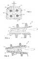
- FIG. 1is an exploded top perspective view showing a total disc implant constructed in accordance with one preferred form of the present invention, and illustrating upper and lower end plates with an insert positioned therebetween;
- FIG. 2is a side elevation view of the total disc implant depicted in FIG. 1 ;
- FIG. 3is an enlarged side elevation view of the insert
- FIG. 4is a top plan view of the total disc implant of FIG. 1 , showing axial rotation;
- FIG. 5is an anterior-posterior or sagital sectional view of the total disc implant of FIG. 1 , showing anterior-posterior articulation;
- FIG. 6is a medial-lateral or coronal sectional view of the total disc implant of FIG. 1 , showing medial-lateral articulation;
- FIG. 7is an exploded top perspective view showing a total disc implant constructed in accordance with an alternative preferred form of the present invention.
- FIG. 8is an exploded bottom perspective view of the total disc implant of FIG. 7 ;
- FIG. 9is a side elevation view of the total disc implant depicted in FIG. 7 ;
- FIG. 10is an anterior-posterior or sagital sectional view of the total disc implant of FIG. 7 , showing anterior-posterior articulation;
- FIG. 11is a medial-lateral or coronal sectional view of the total disc implant of FIG. 7 , showing medial-lateral articulation;
- FIG. 12is a top plan view of the total disc implant of FIG. 7 , showing axial rotation;
- FIG. 13is a pair of photomicrographs comparing porosity and pore size between a preferred cancellous structured ceramic material for use in forming one or more portions of the total disc implant, with natural trabecular bone structure of a human lumbar vertebral body;
- FIG. 14is a radiograph showing the preferred cancellous structured ceramic material implanted a condylar bone of a sheep;
- FIG. 15is a back scattered electron (BSE) microscope image showing new bone ingrowth into the preferred cancellous structured ceramic material, and apposition along the host bone/implant interface;
- BSEback scattered electron
- FIG. 16is an exploded top perspective view showing a total disc implant constructed in accordance with a further alternative preferred form of the present invention.
- FIG. 17is a side elevation view of the total disc implant embodiment depicted in FIG. 16 ;
- FIG. 18is an inverted side elevation view of an upper component of the total disc implant embodiment of FIG. 16 ;
- FIG. 19is a top plan view of the total disc implant embodiment of FIG. 16 , showing axial rotation;
- FIG. 20is an anterior-posterior or sagital sectional view of the total disc implant embodiment of FIG. 16 , showing anterior-posterior articulation;
- FIG. 21is a medial-lateral or coronal sectional view of the total disc implant embodiment of FIG. 16 , showing medial-lateral articulation.
- the TDI design of the present inventionis based on the principles of maintaining spine anatomy, restoring function by preserving segmental motion, providing immediate stability, withstanding spine loads safely, and providing rapid osteo-integration between implant/host bone.
- FIGS. 1 and 2show the proposed TDI design for lumbar spine.
- the designfeatures an upper end plate 10 and a lower end plate 12 formed respectively with upper and lower surfaces that engage with the adjacent vertebral bodies (not shown).
- Each end plate 10 , 12includes a solid rim 14 substantially circumscribing the respective upper and lower surface to rest on the cortex of the adjacent vertebral body.
- Fixation elementssuch as fins, teeth or pins 16 protrude axially from the respective upper and lower surfaces of the end plates 10 , 12 to provide anchoring and immediate stability with the adjacent vertebral bodies.
- These upper and lower surfacesinclude or are surface-coated each to define a porous in growth surface 18 to permit and accommodate rapid bone in-growth and osteo-integration for long term stability.
- the anterior-posterior (A-P) and medial-lateral (M-L) dimensions of the upper and lower end plates 10 , 12are chosen to suit typical lumbar/cervical spinal body dimensions, such as an A-P dimension of about 20-25 mm and a M-L dimension of about 28-35 mm as viewed in the illustrative drawings.
- the illustrative end plates 10 , 12further include an anterior to posterior lordotic taper to better restore the natural curvature of spine, as viewed in FIG. 2 which shows each end plate 10 , 12 with a tapered thickness that increases in the anterior to posterior direction. As viewed in FIG.
- this lordotic tapermay provide a posterior spacing between the end plates 10 , 12 of about 8 mm, with the upper and lower surfaces of the end plates 10 , 12 tapering forwardly in the anterior direction at a diverging angle of about 6 degrees.
- the articulating lower surface of the upper end plate 10 , and the articulating upper surface of the lower end plate 12each include a unique contour that permits a substantially normal range flexion in the A-P direction in combination with extension in the M-L direction, while additionally accommodating a limited range of axial rotation.
- These articulating surfaces of the upper and lower end plates 10 , 12respectively engage and articulate with an intervening insert 20 having uniquely contoured upper and lower surfaces.
- the articulating lower surface of the upper end plate 10comprises a part-cylindrical, downwardly convex elongated bearing component or strip 22 defining a bearing surface extending generally in the M-L direction.
- the articulating upper surface of the lower end plate 12comprises a similarly sized and shaped, part-cylindrical and upwardly convex elongated bearing component or strip 24 oriented to define a bearing surface extending generally in the A-P direction.
- the two bearing strips 22 , 24are oriented generally on orthogonal axes relative to each other.
- the insert 20is captured between these bearing strips 22 , 24 , and includes generally part-cylindrical recessed bearing seats 26 and 28 formed respective in the upper and lower sides thereof, generally on mutually orthogonal axis, for respective reception and bearing engagement with the part-cylindrical bearing strips 22 , 24 . Accordingly, the articulating geometry between the upper bearing strip 22 on the upper end plate 10 , with the upper bearing seat 26 on the insert 20 , accommodates A-P rotation or flexion (as viewed in FIG. 5 ), with a preferred range of A-P flexion on the order of about 12-15°.
- the articulating geometry between the lower bearing strip 24 on the lower end plate 12 , with the lower bearing seat 28 on the insert 20accommodates M-L rotation or extension (as viewed in FIG. 6 ), with a preferred range of M-L extension on the order of about 12-15° of lateral bending.
- M-L rotation or extensionas viewed in FIG. 6
- M-L extensionon the order of about 12-15° of lateral bending.
- each bearing seat 26 , 28 formed on the insert 20each have a part-cylindrical contour defined in cross sectional shape by offset radii, as shown best in FIG. 3 .
- each bearing seat 26 , 28is defined by upwardly curving sides shown in the illustrative example of FIG. 3 to be formed on radii of about 7.3 mm, but wherein the centers of these radii are spaced apart or laterally offset by a small increment (0.7 mm in the illustrative example) to provide a relatively flattened base segment interposed between the upwardly curving radiused sides.
- the part-cylindrical bearing seats 26 , 28defined by offset radii, provide a platform permitting a limited amount of axial rotation and translation. That is, the effect of this special asymmetric articulating geometry with offset radii is to accommodate a substantially natural range of anatomic rotational motion on the order of about plus/minus 5° as viewed in FIG. 4 , while at the same time providing a limit to extreme rotation motion and restoring a “neutral” position following a rotation motion. In such rotation, the radiused sides of the insert 20 initially abut the bearing strips 22 , 24 of the top and bottom plates 10 , 12 (FIG. 4 ).
- this unique TDI articulation geometryfunctions like the natural disc, by limiting axial rotation while permitting normal anatomic flexion-extension and lateral bending motions. No other features such as positive stops or grooves or additional components such as elastomeric materials are necessary.
- FIGS. 5 and 6show the implant design in the extreme lateral bending and flexion-extension positions respectively.
- anatomic combined lateral bending and flexion-extension range of motion(ROM) are permitted for the lumbar implant.
- the total intervertebral heightis in the illustrative embodiment is about 8 mm.
- the designpermits a higher range of motion—up to about 20° for flexion-extension and lateral bending.
- the ROM for the proposed lumbar and cervical spinesare in accord with those reported by Wilke et al xiv, xv and White and Panjabi xvi .
- FIGS. 7-9show an alternate TDI design for lumbar spine.
- the designfeatures an upper end plate 30 and a lower end plate 32 formed respectively with upper and lower surfaces that engage with the adjacent vertebral bodies (not shown).
- Each end plate 30 , 32includes a solid rim 34 substantially circumscribing the respective upper and lower surface to rest on the cortex of the adjacent vertebral body.
- Fixation elementssuch as fins, teeth or pins 36 protrude axially from the respective upper and lower surfaces of the end plates 30 , 32 to provide anchoring and immediate stability with the adjacent vertebral bodies.
- These upper and lower surfacesinclude or are surface-coated each to define a porous in-growth surface 38 to permit and accommodate rapid bone in-growth and osteo-integration for long term stability.
- the A-P and M-L dimensions of the upper and lower end plates 30 , 32are chosen to suit typical lumbar/cervical spinal body dimensions.
- the illustrative end plates 30 , 32further include an anterior to posterior lordotic taper to better restore the natural curvature of spine, as viewed in FIG. 9 .
- the articulating lower surface of the upper end plate 30 , and the articulating upper surface of the lower end plate 32each include a unique bearing component defining a unique bearing surface or contour that permits a substantially normal range flexion in the A-P direction in combination with extension in the M-L direction, while additional accommodating a limited range of axial rotation.
- These articulating surfaces of the upper and lower end plates 30 , 32respectively engage and articulate with each other.
- the articulating surface of the upper end plate 30comprises a part-cylindrical, downwardly concave bearing component or member 42 with its axis extending generally perpendicular to the M-L direction.
- the articulating surface of the lower end plate 32comprises a similarly sized and shaped, part-cylindrical and upwardly convex elongated bearing component or strip 44 oriented to extend generally in the A-P direction.
- the two bearing surfaces 42 , 44are oriented generally on orthogonal axes relative to each other.
- the articulating geometry between the upper bearing surface 42 on the upper end plate 30accommodates A-P rotation or flexion (as viewed in FIG. 10 ), with a preferred range of A-P flexion on the order of about 12-15°.
- the articulating geometry between the lower bearing strip 44 on the lower end plate 30accommodates M-L rotation or extension (as viewed in FIG. 11 ), with a preferred range of M-L extension on the order of about 12-15° of lateral bending.
- the part-cylindrical bearing surfaces 42 , 44 formed on the upper and lower end plates 30 and 32each have a part-cylindrical contour defined by offset radii, similar to those shown best in FIG. 3 .
- each bearing surface 42 , 44is defined by curving sides to be formed as arcs of a circle, but wherein the centers of these arcs are spaced a part or laterally offset by a small increment to provide a relatively flattened rotational platform interposed between the curving radiused sides.
- the part-cylindrical bearing surfaces 42 , 44 , and the flattened rotational platform defined by offset radiiprovide a platform permitting a limited amount of axial rotation and translation. That is, the effect of this special asymmetric articulating geometry with offset radii is to accommodate a substantially natural range of anatomic rotational motion on the order of about plus/minus 5° as viewed in FIG. 12 , while at the same time providing a limit to extreme rotation motion and restoring a “neutral” position following a rotation motion.
- this alternate two piece unique TDI articulation geometry as shown in FIGS. 7-9functions like the natural disc, by limiting axial rotation while permitting normal anatomic flexion-extension and lateral bending motions. No other features such as positive stops or grooves or additional components such as elastomeric materials are necessary.
- Another unique advantage of this designis that it does not require an insert, thus avoiding any risk of the insert from being dislodged or otherwise impinging on the spine.
- the implant designcan be flexible enough to permit a higher range of motion—up to about 20° for flexion-extension and lateral bending for cervical spine disc replacements.
- the ROM for the proposed lumbar and cervical spinesare in accord with those reported by Wilke et al xvii, xviii and White and Panjabi xix .
- FIGS. 16-21illustrate a further alternative preferred form of the TDI of the present invention, based again on principles of maintaining natural spinal anatomy, restoring function by preserving segmental motion, providing immediate implantation stability, withstanding normal spinal loads in a safe and stable manner, and providing relatively rapid and improved osteo-integration between TDI surface and host bone.
- FIGS. 16-17illustrate an upper end plate 60 and a lower end plate 62 similar to those shown and described in FIGS. 1-9 , but respectively including convex or domed upper and lower surfaces for engaging adjacent vertebral bodies having an overall size and shape suitable for implantation into the lumbar spinal region. These domed surfaces are surface-coated with or otherwise define porous bone in-growth surfaces 68 for relatively rapid osteo-integration with porous or cancellous interior structure of prepared adjacent vertebral bodies.
- a solid rim 64 on each end plateis provided for stable seated engagement with the circumferential or cortical rim of the prepared adjacent vertebral bodies, so that center loading and potential subsidence is substantially eliminated or avoided.
- Protruding fixation elements 66such as the illustrative fins are also provided for anchoring the end plates 60 , 62 , and to provide substantial immediate stability.
- the illustrative drawingsshow these fins 66 to have a generally curved posterior edge and a generally vertical anterior edge suitable for anterior placement.
- a modified fin shape of generally pyramidal configuration with a triangular basemay be used.
- FIGS. 16-21may incorporate anterior-posterior and medial-lateral dimensions suitable for specific lumbar or cervical spinal body dimensions.
- the end plates 60 , 62have an anterior to posterior lordotic taper (FIG. 17 ), similar that shown in FIGS. 2 and 9 , for better fit and restoration of the natural spinal curvature.
- upper end plate 60includes a depending, part-cylindrical bearing strip 72 which is elongated in the anterior-posterior (sagital) direction, wherein this bearing strip 72 incorporates generally convex opposite end segments separated by a centrally positioned and generally concave segment defining a concave bearing seat 76 .
- the lower end plate 62includes an upwardly projecting, part-cylindrical bearing strip 74 which is elongated along an axis generally orthogonal to the upper bearing strip 72 .
- each bearing strip 72 , 74is shaped with generally convex opposite end segments, preferably to expand or taper with increasing diametric size ( FIGS. 16 and 18 ) from the opposite ends thereof in a direction toward the associated central concave bearing seat 76 , 78 . As illustrated in inverted configuration in FIG.
- both concave bearing seats 76 , 78which are also oriented on generally orthogonal axes relative to each other are desirably formed on offset radii as previously shown and described relative to FIGS. 1-9 , to define upwardly curving opposed sides with a relatively flattened base segment interposed therebetween.
- the above described articulating geometryaccommodates limited relative rotation ( FIG. 19 ) within a limited range of about plus/minus 5°, medial-lateral flexion-extension ( FIG. 20 ) within a limited range of up to about 12-15°, and anterior-posterior lateral bending ( FIG. 21 ) within a limited range of up to about 10-12°.
- the effect of this articulating geometry including the above-described concave surfaces formed on offset radiifunctions to limit extreme motion and correspondingly to provide an inherent tendency to return to or restore a neutral or substantially centered position between the articulating components.
- the combination of the offset radii for the concave bearing seats 76 , 78 and their engagement on orthogonal axesresults in sliding of the upper end plate 60 along the lower end plate 62 for distracting the intervertebral disc space.
- This distractionincreases loading in the cranial-caudal direction on the TDI, which in turn naturally results in a counteracting force tending to resist the distraction, thereby urging the components and the vertebral bodies affixed thereto back toward a neutral position.
- the TDI articulation geometryfunctions like the natural disc, by limiting axial rotation while permitting normal anatomic flexion-extension and lateral bending motions. No other features such as positive stops or grooves or additional components such as elastomeric materials are necessary.
- FIGS. 20 and 21respectively show the TDI in extreme flexion-extension and extreme lateral bending positions for the illustrative lumbar implant, it is noted the ROM permitted for a cervical implant can be varied typically within a wider range of motion.
- the proposed TDIis a motion preserving prosthetic disc for replacing a damaged disc, which restores anatomic motion and function, provides immediate and long term stability and virtually eliminates risk from wear particles.
- the TDI end plates and/or the insertare constructed from rigid-on-rigid materials, such as by use of a selected ceramic material, or a selected biocompatible metal, or combinations thereof.
- ultra-low wear bearing materialssuch as enhanced Si 3 N 4 ceramic is used, as shown and described in copending U.S. Ser. No. 10/171,376, filed Jun. 13, 2002, which is incorporated by reference herein.
- Si 3 N 4 cups/Si 3 N 4 headshave demonstrated high safety and reliability in laboratory hip simulator and mechanical tests, and are cost competitive compared to conventional ceramic-on-ceramic bearings.
- Si 3 N 4 ceramicshave 100% higher fracture toughness than alumina and 50% higher fracture toughness than zirconia, a 50% increase in fracture strength over alumina and no issues with phase transformation or aging like zirconia. They also have very favorable wear performance as determined over a 3 million cycle test.
- Wear performance of these bearingsindicates that they are better than metal-on-metal bearings by over one order of magnitude, 2 orders of magnitude better than metal-PE and 20 times lower than metal-XPE bearings.
- These bearing materialsare preferred for use in the TDI of the present invention.
- CSCbio-mimetic, bioactive, cancellous structured ceramics
- CSC ceramicspossess [a] high load bearing capability, [b] strong bio-mimetic scaffold necessary for ingrowth and rapid integration with host bone, [c] a bio-active coating comprising of calcium phosphate (Ca—P), which like hydroxy-apatite (HAP) or tri-calcium phosphate (TCP) is similar to bone mineral, a Ca deficient, carbonate containing apatite similar to Ca 10 (PO 4 ) 6 (OH) 2 and capable of binding to osteo-inductive factors such as autogenous cells, and [d] good imaging characteristics unlike metals.
- Ca—Pcalcium phosphate
- HAPhydroxy-apatite
- TCPtri-calcium phosphate
- the porosity and pore size of these CSC ceramicscan be tailored to allow for [a] optimal ingress of vascularization, [b] ease of carrying/delivering ex-vivo expanded viable hMSCs within the cancellous core, and [c] mechanical property match with bone to allow optimal stress transmission.
- the porosity/pore size structure for a load bearing CSChave been selected using previous reports on the optimal structure for grafts by Robey and co-workers.
- xxiBobyn et al xxii,xxiii and Bloebaum et al xxiv .
- the optimal pore size for achieving bone ingrowthranged between 100 to 530 ⁇ m, with up to 55% porosity.
- the resultant porous structure 50 of the CSC ceramicclosely resembles the porous structure 52 of trabecular bone, as viewed in FIG. 13 .
- FIGS. 14 and 15show a typical section, with a CSC plug 54 implanted with condylar bone 56 .
- the CSC plugswere coated with a uniform amorphous Ca—P coating and pores filled with host bone marrow aspirate. The combination of the Ca—P coating and host osteo-inductive factors resulted in favorable osteoinductive activity.
- the implant/bone interfaceis depicted in FIG. 15 by reference numeral 58 .
- Reference numeral 61refers to a region of bone apposition
- reference numeral 63indicates bone ingrowth.
- Histologic evaluation(Giemsa stain) of thin sections revealed vigorous bone formation both at the implant/host bone interface and within the pores of the scaffold, indicative of the interconnection between pores.
- new boneformed at the surface.
- Complete interconnection of the poresallowed osteoblastic activity to penetrate deeper into the implant and complete vascular penetration was observed in the histology evaluation.
- evidence of woven bonewas observed.
- the bonewas viable as detected by osteocytes in the lacunae. Little fibrous encapsulation, presence of macrophage or giant cells was detected.
- the CSC structurewill be used to fabricate the porous in-growth surface 18 integrally with the dense bearing surface end plates of the TDI implant as shown in FIG. 1 . Excellent short/long term stability and imaging characteristics will be obtained.
- the instant TDIis an ideal prosthetic inter-vertebral disc implant.
- the designmaintains intervertebral anatomy.
- the TDI designrestores spinal segmental motion and provides a resistance to extreme rotation of the spine as is desired.
- the biconcave insert 20with its thicker rim 14 will naturally prevent protrusion and resist dislocation. This will minimize risk of pinching nerves or the spinal cord.
- the ceramic disc insert materialoffers unprecedented biomechanical safety in carrying and transmitting loads between the vertebrae.
- the insertis both biocompatible and bio-stable: the disc or any of its wear by-products, are highly unlikely to cause adverse tissue reactions. These attributes if demonstrated, will enable the proposed TDI to leapfrog the present generation of disc implants undergoing clinical testing.
Landscapes
- Health & Medical Sciences (AREA)
- Engineering & Computer Science (AREA)
- Biomedical Technology (AREA)
- Neurology (AREA)
- Orthopedic Medicine & Surgery (AREA)
- Cardiology (AREA)
- Oral & Maxillofacial Surgery (AREA)
- Transplantation (AREA)
- Heart & Thoracic Surgery (AREA)
- Vascular Medicine (AREA)
- Life Sciences & Earth Sciences (AREA)
- Animal Behavior & Ethology (AREA)
- General Health & Medical Sciences (AREA)
- Public Health (AREA)
- Veterinary Medicine (AREA)
- Prostheses (AREA)
- Materials For Medical Uses (AREA)
Abstract
Description
- [a] Long term wear of the articulating PE “disc”, especially in cases where small bony fragments are entrapped between the articulating surfaces,
- [b] Osteolysis and subsequent aseptic loosening and instability of the implant as a result of the PE wear debris,
- [c] Protrusion of the disc from the disc space due to creep or fatigue related gradual changes in dimensional characteristics, and
- [d] Difficulty of diagnostic imaging the intervertebral region because of electromagnetic artifacts, halos and radiographic shadows associated with the metal end plates.
- 1. Universal Design for Lumbar and Cervical Applications: the design, as shown, is suited for a lumbar implant. Suitable modifications of its dimensions permits its use as a cervical disc implant. The objective is to offer a range of sizes that fit the spine in any intervertebral disc space, and without alteration of that inter-vertebral space regardless of its natural size or shape.
- 2. Restoration and Preservation of Anatomic Motion: the objective of the total disc implant (TDI) is to restore intervertebral space to its natural pre-morbid dimensions and provide full range of motion including limiting extreme motion just like in normal spines. A further goal is to prevent adjacent segment hypermobility. The proposed TDI is more natural—allowing controlled and limited motion between segments. In contrast to some current designs, the TDI has a special bi-convex articulating contour or geometry which permits “normal” flexion-extension, lateral bending, and limited axial rotation. This geometry is in sharp contrast to some designs which use fixed hard stops (e.g., Flexicore), with the potential for implant loosening, or other discs such as the Charite', ProDisc and Maverick which have passive stops to limit axial rotation, and require the annulus to be tightened for optimal function.
- 3. Minimal End Plate Preparation: by preserving the load bearing cortical bone and minimizing end plate perforation to expose the highly vascular cancellous bone, both immediate stability and long term in-growth is enabled.
- 4. Surgical Technique: the surgical technique for insertion of these implants is consistent with the established methods of disc removal, and requires neither specialized instrumentation nor specialized instrumentation nor specialized surgical technique. In fact, the technique will be similar to that used for over a decade for artificial discs. The technique involves removal of the nucleus pulposus, flattening of the end plates and leaving most of the annular circumferentially intact. The anterior or anterior-lateral aspect of the annulus is removed as needed for TDI placement. Based upon templating the patient spine and using trial implants, the vertebral bodies are distracted to a near maximum needed for optimal placement of the TDI. The fins cut through the end plates and the osteo-integration surface, which may be domed, is forced into contact with the cancellous portion of the adjacent vertebral bodies. Ligamentoxasis is also used to maintain the TDI in place. The surgical goal is to relieve pain by restoring the patient's natural spinal anatomy and allowing for some motion between the diseased vertebral segments, and thereby minimize or avoid adjacent segment hypermobility. Clinical success will be defines by reduction or elimination of patient pain, improvement in function and maintenance of motion with the TDI.
- 5. Extent of Disc Removal: the extent of disc removal can be determined by the surgeon at the time of surgery and can be individualized for each patient. As noted above, the end plate is flattened most of the annulus is left circumferentially intact. It is contemplated that multiple TDI's with variable height end plates insert will be provided in order to restore a unique individual anatomy with a relatively high degree of precision.
- 6. Elimination of Incorrect Implant Size Selection: in those implant systems where a drill is used and significant bone is removed, trials of the implant size must first be made. Furthermore, regardless of the fit, an implant at least as large as the space created by the drilling must be utilized, regardless of the quality of that fit. With the proposed design, no significant bone is removed, and the correct size implants are fitted directly to the inter-vertebral space eliminating the need to guess at the correct implant size before the fact. At the surgeon's discretion and based on the templating of the patient's spine, the surgeon will choose the appropriate implant size in order to restore the patient's spinal anatomy.
- 7. Modular Design: the proposed implant design will be made available in different standardized A-P depths and M-L widths to accommodate the physiological range of inter-vertebral space. The articulating inserts will also be made available in varying heights within typical the physiological range. This will enable standardization of the modular implant system over the lumbar/cervical size ranges.
- 8. Avoidance of Collapse of the Inter-vertebral space: the implant is made from ceramic material many times stronger than bone and will not collapse. The implantation technique and TDI design relies on preservation of the strong vertebral cortex, which is resistant to compression, thus preventing or minimizing migration or subsidence of the TDI into the vertebrae. The large bearing surface area of the implant minimizes the load per unit area on the insert.
- 9. Revisability: the proposed TDI is an inter-vertebral space implant and not a “through vertebrae” cross inter-vertebral space implant. The technique envisioned requires minimal end plate preparation. Furthermore, the design features multiple 2 mm fins which bite into the adjacent vertebral bone for stability. It is expected that revision of the implant, should it become necessary, would be possible with a minimal chance of iatrogenic destruction of the adjacent vertebrae.
- 10. Self-Stabilizing with Rapid Osteo-integration Capability: the implant surface is designed to resist dislodgment with multiple fins assuring immediate anchoring. Long term stability is provided by rapid osteo-integration into the bio-mimetic cancellous structured bony ingrowth layer. Loading the porous layer with osteo-inductive agents can enhance this ingrowth.
- 11. Safety and Versatility: the entire procedure is performed under direct vision and with complete visualization of the adjacent vital structures (e.g., organs, neural structures and blood vessels). The implant also lends itself to a variety of implantation techniques such as minimally invasive surgery, anterior, posterior, lateral or extreme lateral approaches.
- CSCs at 12 weeks have 200% and 50% higher in-growth when compared to porous coated Ti plugs at 12 and 24 weeks, respectively.
- New bone forms on the surface in CSCs (similar to HAP/TCP grafts) rather than near the surface (typical for bio-inert materials such as Ti or alumina), and
- Penetration depth of new bone is significantly higher.
Claims (25)
Priority Applications (6)
| Application Number | Priority Date | Filing Date | Title |
|---|---|---|---|
| US10/737,108US6994727B2 (en) | 2002-12-17 | 2003-12-15 | Total disc implant |
| US11/149,627US7758646B2 (en) | 2002-12-17 | 2005-06-09 | Total disc implant |
| US11/858,016US7771481B2 (en) | 2002-12-17 | 2007-09-19 | Total disc implant |
| US12/803,889US8016890B2 (en) | 2002-12-17 | 2010-07-07 | Total disc implant |
| US13/136,886US8377134B2 (en) | 2002-12-17 | 2011-08-11 | Total disc implant |
| US13/764,022US20130304210A1 (en) | 2002-12-17 | 2013-02-11 | Total Disc Implant |
Applications Claiming Priority (2)
| Application Number | Priority Date | Filing Date | Title |
|---|---|---|---|
| US43409202P | 2002-12-17 | 2002-12-17 | |
| US10/737,108US6994727B2 (en) | 2002-12-17 | 2003-12-15 | Total disc implant |
Related Child Applications (1)
| Application Number | Title | Priority Date | Filing Date |
|---|---|---|---|
| US11/149,627DivisionUS7758646B2 (en) | 2002-12-17 | 2005-06-09 | Total disc implant |
Publications (2)
| Publication Number | Publication Date |
|---|---|
| US20040133281A1 US20040133281A1 (en) | 2004-07-08 |
| US6994727B2true US6994727B2 (en) | 2006-02-07 |
Family
ID=32681994
Family Applications (6)
| Application Number | Title | Priority Date | Filing Date |
|---|---|---|---|
| US10/737,108Expired - Fee RelatedUS6994727B2 (en) | 2002-12-17 | 2003-12-15 | Total disc implant |
| US11/149,627Expired - Fee RelatedUS7758646B2 (en) | 2002-12-17 | 2005-06-09 | Total disc implant |
| US11/858,016Expired - Fee RelatedUS7771481B2 (en) | 2002-12-17 | 2007-09-19 | Total disc implant |
| US12/803,889Expired - Fee RelatedUS8016890B2 (en) | 2002-12-17 | 2010-07-07 | Total disc implant |
| US13/136,886Expired - Fee RelatedUS8377134B2 (en) | 2002-12-17 | 2011-08-11 | Total disc implant |
| US13/764,022AbandonedUS20130304210A1 (en) | 2002-12-17 | 2013-02-11 | Total Disc Implant |
Family Applications After (5)
| Application Number | Title | Priority Date | Filing Date |
|---|---|---|---|
| US11/149,627Expired - Fee RelatedUS7758646B2 (en) | 2002-12-17 | 2005-06-09 | Total disc implant |
| US11/858,016Expired - Fee RelatedUS7771481B2 (en) | 2002-12-17 | 2007-09-19 | Total disc implant |
| US12/803,889Expired - Fee RelatedUS8016890B2 (en) | 2002-12-17 | 2010-07-07 | Total disc implant |
| US13/136,886Expired - Fee RelatedUS8377134B2 (en) | 2002-12-17 | 2011-08-11 | Total disc implant |
| US13/764,022AbandonedUS20130304210A1 (en) | 2002-12-17 | 2013-02-11 | Total Disc Implant |
Country Status (5)
| Country | Link |
|---|---|
| US (6) | US6994727B2 (en) |
| EP (1) | EP1572042A4 (en) |
| JP (2) | JP2006510452A (en) |
| AU (1) | AU2003297195A1 (en) |
| WO (1) | WO2004058098A2 (en) |
Cited By (128)
| Publication number | Priority date | Publication date | Assignee | Title |
|---|---|---|---|---|
| US20030174929A1 (en)* | 2002-03-15 | 2003-09-18 | Rodgers Murray Steven | Self-shadowing MEM structures |
| US20040024462A1 (en)* | 2002-04-12 | 2004-02-05 | Ferree Bret A. | Spacerless artificial disc replacements |
| US20040176843A1 (en)* | 2003-03-06 | 2004-09-09 | Rafail Zubok | Instrumentation and methods for use in implanting a cervical disc replacement device |
| US20040187981A1 (en)* | 2002-04-05 | 2004-09-30 | Masaharu Ueda | Pealite base rail excellent in wear resistance and ductility and method for production thereof |
| US20040225366A1 (en)* | 2003-02-12 | 2004-11-11 | Sdgi Holdings, Inc. | Articular disc prosthesis for anterior-oblique insertion |
| US20040243240A1 (en)* | 2001-05-04 | 2004-12-02 | Jacques Beaurain | Intervertebral disc prosthesis and fitting tools |
| US20050010215A1 (en)* | 2001-10-18 | 2005-01-13 | Joel Delecrin | Plate for osteosynthesis device and preassembling method |
| US20050021145A1 (en)* | 2003-05-27 | 2005-01-27 | Spinalmotion, Inc. | Prosthetic disc for intervertebral insertion |
| US20050033435A1 (en)* | 2003-08-04 | 2005-02-10 | Spine Next | Intervertebral disk prosthesis |
| US20050154461A1 (en)* | 2004-01-09 | 2005-07-14 | Sdgi Holdings, Inc. | Dual articulating spinal device and method |
| US20050154467A1 (en)* | 2004-01-09 | 2005-07-14 | Sdgi Holdings, Inc. | Interconnected spinal device and method |
| US20050154465A1 (en)* | 2004-01-09 | 2005-07-14 | Sdgi Holdings, Inc. | Split spinal device and method |
| US20050154464A1 (en)* | 2004-01-09 | 2005-07-14 | Sdgi Holdings, Inc. | Support structure device and method |
| US20050171610A1 (en)* | 2004-01-09 | 2005-08-04 | Sdgi Holdings, Inc. | Mobile bearing spinal device and method |
| US20050192673A1 (en)* | 2003-10-14 | 2005-09-01 | Saltzman Charles L. | Ankle prosthesis and method for implanting ankle prosthesis |
| US20050197706A1 (en)* | 2004-02-04 | 2005-09-08 | Ldr Medical, Inc. | Intervertebral disc prosthesis |
| US20050228497A1 (en)* | 2002-04-23 | 2005-10-13 | Ferree Bret A | Artificial disc replacements with natural kinematics |
| US20050246024A1 (en)* | 2004-04-28 | 2005-11-03 | Ldr Medical, Inc. | Intervertebral disc prosthesis |
| US20050251170A1 (en)* | 2004-05-07 | 2005-11-10 | Ethicon Endo-Surgery, Inc. | Instrument for effecting anastomosis of respective tissues defining two body lumens |
| US20050251260A1 (en)* | 2002-08-15 | 2005-11-10 | David Gerber | Controlled artificial intervertebral disc implant |
| US20050251262A1 (en)* | 2002-09-19 | 2005-11-10 | Spinalmotion, Inc. | Intervertebral prosthesis |
| US20060004453A1 (en)* | 2004-06-30 | 2006-01-05 | Depuy Spine, Inc. | Ceramic disc prosthesis |
| US20060030857A1 (en)* | 2004-08-06 | 2006-02-09 | Spinalmotion, Inc. | Methods and apparatus for intervertebral disc prosthesis insertion |
| US20060085076A1 (en)* | 2004-10-15 | 2006-04-20 | Manoj Krishna | Posterior spinal arthroplasty-development of a new posteriorly inserted artificial disc and an artificial facet joint |
| US20060136063A1 (en)* | 2004-12-22 | 2006-06-22 | Ldr Medical | Intervertebral disc prosthesis |
| US20060149372A1 (en)* | 2004-12-17 | 2006-07-06 | Paxson Robert D | Artificial spinal disc |
| US20060155377A1 (en)* | 2002-11-05 | 2006-07-13 | Jacques Beaurain | Intervertebral disk prosthesis |
| US20060178744A1 (en)* | 2005-02-04 | 2006-08-10 | Spinalmotion, Inc. | Intervertebral prosthetic disc with shock absorption |
| US20060217809A1 (en)* | 2005-03-24 | 2006-09-28 | Accin Corporation | Intervertebral disc replacement device |
| US20060229728A1 (en)* | 2005-04-12 | 2006-10-12 | Mckay William F | Methods and devices for preserving motion in an articulating prosthetic disc |
| US20060259147A1 (en)* | 2003-01-17 | 2006-11-16 | Manoj Krishna | Articulating spinal disc prosthesis |
| US20070032875A1 (en)* | 2005-08-04 | 2007-02-08 | Terence Blacklock | Orthopaedic Medical Device |
| US20070088441A1 (en)* | 2004-06-30 | 2007-04-19 | Synergy Disc Replacement, Inc. | Artificial Spinal Disc |
| US20070162130A1 (en)* | 2005-11-30 | 2007-07-12 | Ralph Rashbaum | Intervertebral disc prosthesis and instrumentation for insertion of the prosthesis between the vertebrae |
| US20070179616A1 (en)* | 2006-01-30 | 2007-08-02 | Sdgi Holdings, Inc. | Posterior joint replacement device |
| US20070179618A1 (en)* | 2006-01-31 | 2007-08-02 | Sdgi Holdings, Inc. | Intervertebral prosthetic disc |
| US20070179615A1 (en)* | 2006-01-31 | 2007-08-02 | Sdgi Holdings, Inc. | Intervertebral prosthetic disc |
| US20070191945A1 (en)* | 2006-01-30 | 2007-08-16 | Sdgi Holdings, Inc. | Posterior joint replacement device |
| US20070270951A1 (en)* | 2006-02-15 | 2007-11-22 | Reginald James Davis | Transforaminal intersomatic cage for an intervertebral fusion graft and an instrument for implanting the cage |
| US20070270959A1 (en)* | 2006-04-18 | 2007-11-22 | Sdgi Holdings, Inc. | Arthroplasty device |
| US20070288094A1 (en)* | 2006-06-08 | 2007-12-13 | Manoj Krishna | System and method for lumbar arthroplasty |
| US20080027547A1 (en)* | 2006-07-27 | 2008-01-31 | Warsaw Orthopedic Inc. | Prosthetic device for spinal joint reconstruction |
| US20080045968A1 (en)* | 2006-08-18 | 2008-02-21 | Warsaw Orthopedic, Inc. | Instruments and Methods for Spinal Surgery |
| US20080051901A1 (en)* | 2006-07-28 | 2008-02-28 | Spinalmotion, Inc. | Spinal Prosthesis with Multiple Pillar Anchors |
| US20080065211A1 (en)* | 2006-07-18 | 2008-03-13 | Accin Corporation | Intervertebral disc replacement device |
| US20080125864A1 (en)* | 2006-04-12 | 2008-05-29 | Spinalmotion, Inc. | Posterior Spinal Device and Method |
| US20080133013A1 (en)* | 2004-06-30 | 2008-06-05 | Synergy Disc Replacement, Inc. | Artificial Spinal Disc |
| US20080172090A1 (en)* | 2007-01-12 | 2008-07-17 | Warsaw Orthopedic, Inc. | Spinal Prosthesis Systems |
| US20080200984A1 (en)* | 2007-02-16 | 2008-08-21 | Ldr Medical | Intervertebral Disc Prosthesis Insertion Assemblies |
| US20080215156A1 (en)* | 2004-06-30 | 2008-09-04 | Synergy Disc Replacement | Joint Prostheses |
| US20080221689A1 (en)* | 2007-03-10 | 2008-09-11 | Christopher Chaput | Artificial disc with unique articulating geometry and associated methods |
| US20080234823A1 (en)* | 2007-01-19 | 2008-09-25 | Landry Michael E | Artificial functional spinal unit system and method for use |
| US20090043391A1 (en)* | 2007-08-09 | 2009-02-12 | Spinalmotion, Inc. | Customized Intervertebral Prosthetic Disc with Shock Absorption |
| US20090062920A1 (en)* | 2006-02-23 | 2009-03-05 | Faneuil Innovations Investment Ltd. | Intervertebral disc replacement |
| US20090076614A1 (en)* | 2007-09-17 | 2009-03-19 | Spinalmotion, Inc. | Intervertebral Prosthetic Disc with Shock Absorption Core |
| US20090076616A1 (en)* | 2004-06-30 | 2009-03-19 | Synergy Disc | Systems and Methods for Vertebral Disc Replacement |
| US20090105835A1 (en)* | 2007-10-22 | 2009-04-23 | Spinalmotion, Inc. | Vertebral Body Replacement and Method for Spanning a Space Formed upon Removal of a Vertebral Body |
| US20090105832A1 (en)* | 2007-06-08 | 2009-04-23 | Ldr Medical | Intersomatic cage, intervertebral prosthesis, anchoring device and implantation instruments |
| USD597674S1 (en) | 2004-10-21 | 2009-08-04 | Disc Motion Technologies, Inc. | Concave intervertebral disc prosthesis |
| USD598105S1 (en) | 2004-10-21 | 2009-08-11 | Disc Motion Technologies, Inc. | Convex intervertebral disc prosthesis |
| US20090204213A1 (en)* | 2008-02-13 | 2009-08-13 | Depuy Products, Inc. | Metallic implants |
| US7575599B2 (en) | 2004-07-30 | 2009-08-18 | Spinalmotion, Inc. | Intervertebral prosthetic disc with metallic core |
| US7575600B2 (en) | 2004-09-29 | 2009-08-18 | Kyphon Sarl | Artificial vertebral disk replacement implant with translating articulation contact surface and method |
| US20090216241A1 (en)* | 2005-06-29 | 2009-08-27 | Ldr Medical | Instrumentation and Methods for Inserting an Intervertebral Disc Prosthesis |
| US20090216330A1 (en)* | 2004-09-23 | 2009-08-27 | Christophe Geisert | System and method for an intervertebral implant |
| US20090234458A1 (en)* | 2008-03-11 | 2009-09-17 | Spinalmotion, Inc. | Artificial Intervertebral Disc With Lower Height |
| US20090248161A1 (en)* | 2008-03-20 | 2009-10-01 | K2M, Inc. | Artificial disc replacement device |
| US20090254183A1 (en)* | 2004-01-09 | 2009-10-08 | Warsaw Orthopedic, Inc. | Spinal Arthroplasty Device and Method |
| US20090276051A1 (en)* | 2008-05-05 | 2009-11-05 | Spinalmotion, Inc. | Polyaryletherketone Artificial Intervertebral Disc |
| US20100004746A1 (en)* | 2008-07-02 | 2010-01-07 | Spinalmotion, Inc. | Limited Motion Prosthetic Intervertebral Disc |
| US20100016972A1 (en)* | 2008-07-17 | 2010-01-21 | Spinalmotion, Inc. | Artificial Intervertebral Disc Placement System |
| US20100016973A1 (en)* | 2008-07-18 | 2010-01-21 | Spinalmotion, Inc. | Posterior Prosthetic Intervertebral Disc |
| US20100030337A1 (en)* | 2008-08-04 | 2010-02-04 | Nasser Ani | Spine Surgery Technique And System |
| US20100030335A1 (en)* | 2008-01-25 | 2010-02-04 | Spinalmotion, Inc. | Compliant Implantable Prosthetic Joint With Preloaded Spring |
| US20100049040A1 (en)* | 2003-01-31 | 2010-02-25 | Spinalmotion, Inc. | Spinal Midline Indicator |
| US20100069976A1 (en)* | 2003-01-31 | 2010-03-18 | Spinalmotion, Inc. | Intervertebral Prosthesis Placement Instrument |
| US20100087868A1 (en)* | 2008-04-11 | 2010-04-08 | Spinalmotion, Inc. | Motion Limiting Insert For An Artificial Intervertebral Disc |
| US20100094426A1 (en)* | 2008-10-14 | 2010-04-15 | Grohowski Jr Joseph A | Hybrid intervertebral spinal implant |
| US20100100186A1 (en)* | 2003-03-06 | 2010-04-22 | Spinecore, Inc. | Instrumentation and methods for use in implanting a cervical disc replacement device |
| US7708778B2 (en) | 2003-08-05 | 2010-05-04 | Flexuspine, Inc. | Expandable articulating intervertebral implant with cam |
| US7785351B2 (en) | 2003-08-05 | 2010-08-31 | Flexuspine, Inc. | Artificial functional spinal implant unit system and method for use |
| US20100241231A1 (en)* | 2009-02-20 | 2010-09-23 | Marino James F | Intervertebral fixation device |
| US7842088B2 (en) | 2005-09-23 | 2010-11-30 | Ldr Medical | Intervertebral disc prosthesis |
| US20100324688A1 (en)* | 2009-06-18 | 2010-12-23 | Mekatronix | Intervertebral spinal disc prosthesis |
| US20110040331A1 (en)* | 2009-05-20 | 2011-02-17 | Jose Fernandez | Posterior stabilizer |
| US20110046628A1 (en)* | 2009-08-24 | 2011-02-24 | Jamali Amir A | Method and apparatus for allograft disc transplantation |
| US7909869B2 (en) | 2003-08-05 | 2011-03-22 | Flexuspine, Inc. | Artificial spinal unit assemblies |
| US7927375B2 (en) | 2008-09-12 | 2011-04-19 | Doty Keith L | Dynamic six-degrees-of-freedom intervertebral spinal disc prosthesis |
| US8038713B2 (en) | 2002-04-23 | 2011-10-18 | Spinecore, Inc. | Two-component artificial disc replacements |
| US8118869B2 (en) | 2006-03-08 | 2012-02-21 | Flexuspine, Inc. | Dynamic interbody device |
| US8157844B2 (en) | 2007-10-22 | 2012-04-17 | Flexuspine, Inc. | Dampener system for a posterior stabilization system with a variable length elongated member |
| US8162994B2 (en) | 2007-10-22 | 2012-04-24 | Flexuspine, Inc. | Posterior stabilization system with isolated, dual dampener systems |
| US8182514B2 (en) | 2007-10-22 | 2012-05-22 | Flexuspine, Inc. | Dampener system for a posterior stabilization system with a fixed length elongated member |
| US8187330B2 (en) | 2007-10-22 | 2012-05-29 | Flexuspine, Inc. | Dampener system for a posterior stabilization system with a variable length elongated member |
| US8221457B2 (en) | 2001-10-18 | 2012-07-17 | Ldr Medical | Progressive approach osteosynthesis device and preassembly method |
| US8267965B2 (en) | 2007-10-22 | 2012-09-18 | Flexuspine, Inc. | Spinal stabilization systems with dynamic interbody devices |
| US8277505B1 (en) | 2011-06-10 | 2012-10-02 | Doty Keith L | Devices for providing up to six-degrees of motion having kinematically-linked components and methods of use |
| US8287598B1 (en) | 2011-12-05 | 2012-10-16 | TrueMotion Spine, Inc. | True spinal motion preserving, shock absorbing, intervertebral spinal disc prosthesis |
| US8353964B2 (en) | 2010-11-04 | 2013-01-15 | Carpenter Clyde T | Anatomic total disc replacement |
| US8523912B2 (en) | 2007-10-22 | 2013-09-03 | Flexuspine, Inc. | Posterior stabilization systems with shared, dual dampener systems |
| US8673009B2 (en) | 2004-10-21 | 2014-03-18 | Spinadyne, Inc. | Spinal prosthesis and facet joint prosthesis |
| US8858636B2 (en) | 2010-04-09 | 2014-10-14 | DePuy Synthes Products, LLC | Intervertebral implant |
| US8864832B2 (en) | 2007-06-20 | 2014-10-21 | Hh Spinal Llc | Posterior total joint replacement |
| US8940051B2 (en) | 2011-03-25 | 2015-01-27 | Flexuspine, Inc. | Interbody device insertion systems and methods |
| US9039774B2 (en) | 2012-02-24 | 2015-05-26 | Ldr Medical | Anchoring device and system for an intervertebral implant, intervertebral implant and implantation instrument |
| US9044337B2 (en) | 2009-12-31 | 2015-06-02 | Ldr Medical | Anchoring device and system for an intervertebral implant, intervertebral implant and implantation instrument |
| US9051639B2 (en) | 2011-09-15 | 2015-06-09 | Amedica Corporation | Coated implants and related methods |
| US9078765B2 (en) | 2001-07-13 | 2015-07-14 | Ldr Medical | Vertebral cage device with modular fixation |
| US9289310B2 (en) | 2007-03-10 | 2016-03-22 | Spinesmith Partners, L.P. | Artificial disc with post and modular collar |
| US9301853B2 (en) | 2010-04-09 | 2016-04-05 | DePuy Synthes Products, Inc. | Holder for implantation and extraction of prosthesis |
| US9370609B2 (en) | 2013-01-08 | 2016-06-21 | Praxis Powder Technology, Inc. | High strength injection molded orthopedic devices |
| US9463091B2 (en) | 2009-09-17 | 2016-10-11 | Ldr Medical | Intervertebral implant having extendable bone fixation members |
| US9492288B2 (en) | 2013-02-20 | 2016-11-15 | Flexuspine, Inc. | Expandable fusion device for positioning between adjacent vertebral bodies |
| US9517144B2 (en) | 2014-04-24 | 2016-12-13 | Exactech, Inc. | Limited profile intervertebral implant with incorporated fastening mechanism |
| US9526627B2 (en) | 2011-11-17 | 2016-12-27 | Exactech, Inc. | Expandable interbody device system and method |
| US9655741B2 (en) | 2003-05-27 | 2017-05-23 | Simplify Medical Pty Ltd | Prosthetic disc for intervertebral insertion |
| US9693874B2 (en) | 2013-03-15 | 2017-07-04 | Blackstone Medical, Inc. | Composite spinal interbody device and method |
| US20170202676A1 (en)* | 2014-07-19 | 2017-07-20 | Manfred Muhlbrauer | Intervertebral disc implant and method for restoring function to a damaged functional spinal unit |
| US9925295B2 (en) | 2012-05-09 | 2018-03-27 | Amedica Corporation | Ceramic and/or glass materials and related methods |
| US9937050B2 (en) | 2013-05-16 | 2018-04-10 | Ldr Medical | Vertebral implant, vertebral fastening device of the implant and implant instrumentation |
| US10335288B2 (en) | 2007-03-10 | 2019-07-02 | Spinesmith Partners, L.P. | Surgical implant secured by pegs and associated methods |
| US10398565B2 (en) | 2014-04-24 | 2019-09-03 | Choice Spine, Llc | Limited profile intervertebral implant with incorporated fastening and locking mechanism |
| US10478310B2 (en) | 2014-05-06 | 2019-11-19 | Ldr Medical, S.A.S. | Vertebral implant, device for vertebral attachment of the implant and instrumentation for implantation thereof |
| US10603185B2 (en) | 2004-02-04 | 2020-03-31 | Ldr Medical | Intervertebral disc prosthesis |
| US10806831B2 (en) | 2012-05-09 | 2020-10-20 | Sintx Technologies, Inc. | Antibacterial biomedical implants and associated materials, apparatus, and methods |
| US11452618B2 (en) | 2019-09-23 | 2022-09-27 | Dimicron, Inc | Spinal artificial disc removal tool |
| US11890202B2 (en) | 2007-06-20 | 2024-02-06 | 3Spine, Inc. | Spinal osteotomy |
| US12409046B2 (en) | 2022-04-12 | 2025-09-09 | 3Spine, Inc. | Total spinal joint systems with motion moderators |
Families Citing this family (109)
| Publication number | Priority date | Publication date | Assignee | Title |
|---|---|---|---|---|
| US7169182B2 (en) | 2001-07-16 | 2007-01-30 | Spinecore, Inc. | Implanting an artificial intervertebral disc |
| US6673113B2 (en) | 2001-10-18 | 2004-01-06 | Spinecore, Inc. | Intervertebral spacer device having arch shaped spring elements |
| US7695521B2 (en)* | 2001-05-01 | 2010-04-13 | Amedica Corporation | Hip prosthesis with monoblock ceramic acetabular cup |
| EP2055267B1 (en)* | 2001-05-01 | 2013-04-17 | Amedica Corporation | Radiolucent bone graft |
| US7776085B2 (en)* | 2001-05-01 | 2010-08-17 | Amedica Corporation | Knee prosthesis with ceramic tibial component |
| US20050177238A1 (en)* | 2001-05-01 | 2005-08-11 | Khandkar Ashok C. | Radiolucent bone graft |
| EP1408874B1 (en)* | 2001-06-14 | 2012-08-08 | Amedica Corporation | Metal-ceramic composite articulation |
| US7771477B2 (en) | 2001-10-01 | 2010-08-10 | Spinecore, Inc. | Intervertebral spacer device utilizing a belleville washer having radially spaced concentric grooves |
| US7713302B2 (en) | 2001-10-01 | 2010-05-11 | Spinecore, Inc. | Intervertebral spacer device utilizing a spirally slotted belleville washer having radially spaced concentric grooves |
| DE50210270D1 (en) | 2002-03-12 | 2007-07-19 | Cervitech Inc | Intervertebral prosthesis, especially for the cervical spine |
| EP1534194A2 (en)* | 2002-06-26 | 2005-06-01 | Nuvasive, Inc. | Total disc replacement system and related methods |
| AU2003297195A1 (en)* | 2002-12-17 | 2004-07-22 | Amedica Corporation | Total disc implant |
| US7815679B2 (en)* | 2003-01-06 | 2010-10-19 | Cardo Medical, Inc. | Modular motion preservation artificial spinal joint assembly |
| BRPI0409091A (en)* | 2003-04-07 | 2006-04-11 | Cervitech Inc | intervertebral joint prosthesis for the cervical spine |
| US8012212B2 (en)* | 2003-04-07 | 2011-09-06 | Nuvasive, Inc. | Cervical intervertebral disk prosthesis |
| US7105024B2 (en) | 2003-05-06 | 2006-09-12 | Aesculap Ii, Inc. | Artificial intervertebral disc |
| US7291173B2 (en) | 2003-05-06 | 2007-11-06 | Aesculap Ii, Inc. | Artificial intervertebral disc |
| DE20310433U1 (en) | 2003-07-08 | 2003-09-04 | Aesculap AG & Co. KG, 78532 Tuttlingen | Surgical device for inserting dual component implant into appropriate space at spine, comprising particularly shaped holding area |
| DE10330698B4 (en) | 2003-07-08 | 2005-05-25 | Aesculap Ag & Co. Kg | Intervertebral implant |
| US7621956B2 (en)* | 2003-07-31 | 2009-11-24 | Globus Medical, Inc. | Prosthetic spinal disc replacement |
| DE10339170B4 (en)* | 2003-08-22 | 2009-10-15 | Aesculap Ag | Intervertebral implant |
| US7794465B2 (en)* | 2003-09-10 | 2010-09-14 | Warsaw Orthopedic, Inc. | Artificial spinal discs and associated implantation instruments and methods |
| DE502004010737D1 (en)* | 2003-12-09 | 2010-03-25 | Biedermann Motech Gmbh | Height-adjustable intervertebral implant |
| DE10361772B4 (en)* | 2003-12-31 | 2006-10-12 | Henning Kloss | Intervertebral disc implant |
| US7485146B1 (en)* | 2004-03-08 | 2009-02-03 | Nuvasive, Inc. | Total disc replacement system and related methods |
| US7637955B2 (en)* | 2004-03-23 | 2009-12-29 | Warsaw Orthopedic, Inc. | Constrained artificial spinal disc |
| US20050216092A1 (en)* | 2004-03-23 | 2005-09-29 | Sdgi Holdings, Inc. | Constrained artificial implant for orthopaedic applications |
| DE202004009542U1 (en) | 2004-06-16 | 2004-08-12 | Aesculap Ag & Co. Kg | Artificial intervertebral disk, comprising core with intensely curved upper and less curved lower surface |
| US8388667B2 (en) | 2004-08-09 | 2013-03-05 | Si-Bone, Inc. | Systems and methods for the fixation or fusion of bone using compressive implants |
| US9662158B2 (en) | 2004-08-09 | 2017-05-30 | Si-Bone Inc. | Systems and methods for the fixation or fusion of bone at or near a sacroiliac joint |
| US20070156241A1 (en) | 2004-08-09 | 2007-07-05 | Reiley Mark A | Systems and methods for the fixation or fusion of bone |
| US20180228621A1 (en) | 2004-08-09 | 2018-08-16 | Mark A. Reiley | Apparatus, systems, and methods for the fixation or fusion of bone |
| US20060036251A1 (en) | 2004-08-09 | 2006-02-16 | Reiley Mark A | Systems and methods for the fixation or fusion of bone |
| US9949843B2 (en) | 2004-08-09 | 2018-04-24 | Si-Bone Inc. | Apparatus, systems, and methods for the fixation or fusion of bone |
| US8470004B2 (en) | 2004-08-09 | 2013-06-25 | Si-Bone Inc. | Apparatus, systems, and methods for stabilizing a spondylolisthesis |
| US8425570B2 (en) | 2004-08-09 | 2013-04-23 | Si-Bone Inc. | Apparatus, systems, and methods for achieving anterior lumbar interbody fusion |
| US8444693B2 (en) | 2004-08-09 | 2013-05-21 | Si-Bone Inc. | Apparatus, systems, and methods for achieving lumbar facet fusion |
| US8414648B2 (en) | 2004-08-09 | 2013-04-09 | Si-Bone Inc. | Apparatus, systems, and methods for achieving trans-iliac lumbar fusion |
| US7780731B2 (en)* | 2004-11-26 | 2010-08-24 | Spine Solutions, Inc. | Intervertebral implant |
| WO2006058221A2 (en) | 2004-11-24 | 2006-06-01 | Abdou Samy M | Devices and methods for inter-vertebral orthopedic device placement |
| US8911498B2 (en)* | 2005-02-10 | 2014-12-16 | DePuy Synthes Products, LLC | Intervertebral prosthetic disc |
| US7632312B2 (en)* | 2005-03-24 | 2009-12-15 | Neurocare International, Inc. | Artifical lumbar disc |
| GB0508678D0 (en) | 2005-04-28 | 2005-06-08 | Cope Aiden | Motion segment intervertebral disc prosthesis |
| WO2006116853A1 (en)* | 2005-05-02 | 2006-11-09 | Kinetic Spine Technologies Inc. | Spinal stabilisation implant |
| DE102005025685B4 (en)* | 2005-06-03 | 2015-05-21 | Mathys Ag Bettlach | Intervertebral disc implant |
| US8366718B2 (en) | 2005-07-06 | 2013-02-05 | Copf Jr Franz | Preparation device for preparing an intervertebral disc compartment |
| WO2007075878A2 (en)* | 2005-12-22 | 2007-07-05 | Endius, Inc. | Methods and devices for replacement of intervertebral discs |
| US7708777B2 (en)* | 2006-02-03 | 2010-05-04 | Depuy Spine, Inc. | Modular intervertebral disc replacements |
| WO2007095333A2 (en)* | 2006-02-15 | 2007-08-23 | Abdou M S | Devices and methods for inter-vertebral orthopedic device placement |
| US8252058B2 (en) | 2006-02-16 | 2012-08-28 | Amedica Corporation | Spinal implant with elliptical articulatory interface |
| US20070198093A1 (en)* | 2006-02-17 | 2007-08-23 | Amedica Corporation | Spinal implant with offset keels |
| EP2012713A4 (en)* | 2006-04-20 | 2012-06-27 | Re Spine Llc | Intervertebral disc and facet joint prosthesis |
| US8790403B2 (en)* | 2006-04-20 | 2014-07-29 | K2M, Inc. | Monorail system |
| US8303660B1 (en) | 2006-04-22 | 2012-11-06 | Samy Abdou | Inter-vertebral disc prosthesis with variable rotational stop and methods of use |
| WO2007140382A2 (en)* | 2006-05-26 | 2007-12-06 | Abdou M S | Inter-vertebral disc motion devices and methods of use |
| US8275594B2 (en)* | 2006-10-30 | 2012-09-25 | The Regents Of The University Of Michigan | Engineered scaffolds for intervertebral disc repair and regeneration and for articulating joint repair and regeneration |
| US8057481B2 (en) | 2006-11-03 | 2011-11-15 | Innovative Spine, Llc | System and method for providing surgical access to a spine |
| US20080138781A1 (en)* | 2006-12-08 | 2008-06-12 | Warsaw Orthopedic, Inc. | Surgical training model and method for use in facilitating training of a surgical procedure |
| US8715352B2 (en) | 2006-12-14 | 2014-05-06 | Depuy Spine, Inc. | Buckling disc replacement |
| US8034081B2 (en) | 2007-02-06 | 2011-10-11 | CollabComl, LLC | Interspinous dynamic stabilization implant and method of implanting |
| WO2008098228A2 (en) | 2007-02-09 | 2008-08-14 | Diamicron, Inc. | Multi-lobe artificial spine joint |
| BRPI0808018A2 (en)* | 2007-03-07 | 2014-06-17 | Ulrich Gmbh & Co Kg | INTERVERTEBRAL IMPLANT WITH AN ELASTIC COMPONENT |
| US8147558B2 (en)* | 2007-03-30 | 2012-04-03 | Depuy Products, Inc. | Mobile bearing assembly having multiple articulation interfaces |
| US8764841B2 (en) | 2007-03-30 | 2014-07-01 | DePuy Synthes Products, LLC | Mobile bearing assembly having a closed track |
| US8142510B2 (en) | 2007-03-30 | 2012-03-27 | Depuy Products, Inc. | Mobile bearing assembly having a non-planar interface |
| US8147557B2 (en) | 2007-03-30 | 2012-04-03 | Depuy Products, Inc. | Mobile bearing insert having offset dwell point |
| US8328874B2 (en) | 2007-03-30 | 2012-12-11 | Depuy Products, Inc. | Mobile bearing assembly |
| US8956412B2 (en)* | 2007-06-22 | 2015-02-17 | Axiomed, LLC | Artificial disc |
| US9180017B2 (en)* | 2009-10-13 | 2015-11-10 | Nicholas Poulos | Lumbar implant |
| US8906099B2 (en) | 2009-10-13 | 2014-12-09 | Nicholas Poulos | Expandable interbody implant and method |
| US9078766B2 (en) | 2012-07-06 | 2015-07-14 | Intel Corporation | Device and method with power efficient location notification function by periodically deactivating signal-based location service during travel until a wake trigger condition is met |
| US8764806B2 (en) | 2009-12-07 | 2014-07-01 | Samy Abdou | Devices and methods for minimally invasive spinal stabilization and instrumentation |
| US8454692B2 (en)* | 2010-04-18 | 2013-06-04 | F.I.S.H., Llc | Systems and devices having hydromagnetic joints and hydromagnetic springs |
| US8449615B2 (en) | 2010-04-18 | 2013-05-28 | F.I.S.H., Llc | Intervertebral implants having hydromagnetic joints |
| EP2452641A1 (en)* | 2010-11-12 | 2012-05-16 | Kyon AG | Patellar ligament spacer for ACL injuries |
| US9084683B2 (en) | 2011-01-07 | 2015-07-21 | Pbn Spinal Implants, Llc | Spinal implant system and method |
| JP5663674B2 (en) | 2011-03-11 | 2015-02-04 | エフビーシー デバイス エーピーエス | Spine implant, pretreatment instrument and method of use |
| US8747479B2 (en) | 2011-04-26 | 2014-06-10 | Michael A. McShane | Tibial component |
| US8845728B1 (en) | 2011-09-23 | 2014-09-30 | Samy Abdou | Spinal fixation devices and methods of use |
| CN102319129B (en)* | 2011-10-24 | 2015-05-20 | 北京爱康宜诚医疗器材股份有限公司 | Fusion prosthesis |
| CN103239305A (en)* | 2012-02-10 | 2013-08-14 | 北京爱康宜诚医疗器材股份有限公司 | Self-stabilization artificial vertebral body |
| US20130226240A1 (en) | 2012-02-22 | 2013-08-29 | Samy Abdou | Spinous process fixation devices and methods of use |
| US9044321B2 (en) | 2012-03-09 | 2015-06-02 | Si-Bone Inc. | Integrated implant |
| US10363140B2 (en) | 2012-03-09 | 2019-07-30 | Si-Bone Inc. | Systems, device, and methods for joint fusion |
| US8778026B2 (en)* | 2012-03-09 | 2014-07-15 | Si-Bone Inc. | Artificial SI joint |
| EP3818947B1 (en) | 2012-05-04 | 2023-08-30 | SI-Bone, Inc. | Fenestrated implant |
| US9198767B2 (en) | 2012-08-28 | 2015-12-01 | Samy Abdou | Devices and methods for spinal stabilization and instrumentation |
| US9320617B2 (en) | 2012-10-22 | 2016-04-26 | Cogent Spine, LLC | Devices and methods for spinal stabilization and instrumentation |
| WO2014145902A1 (en) | 2013-03-15 | 2014-09-18 | Si-Bone Inc. | Implants for spinal fixation or fusion |
| US9839448B2 (en) | 2013-10-15 | 2017-12-12 | Si-Bone Inc. | Implant placement |
| US11147688B2 (en) | 2013-10-15 | 2021-10-19 | Si-Bone Inc. | Implant placement |
| JP6542362B2 (en) | 2014-09-18 | 2019-07-10 | エスアイ−ボーン・インコーポレイテッドSi−Bone, Inc. | Matrix implant |
| US10166033B2 (en) | 2014-09-18 | 2019-01-01 | Si-Bone Inc. | Implants for bone fixation or fusion |
| US10376206B2 (en) | 2015-04-01 | 2019-08-13 | Si-Bone Inc. | Neuromonitoring systems and methods for bone fixation or fusion procedures |
| US10857003B1 (en) | 2015-10-14 | 2020-12-08 | Samy Abdou | Devices and methods for vertebral stabilization |
| US10744000B1 (en) | 2016-10-25 | 2020-08-18 | Samy Abdou | Devices and methods for vertebral bone realignment |
| US10973648B1 (en) | 2016-10-25 | 2021-04-13 | Samy Abdou | Devices and methods for vertebral bone realignment |
| CN106963523B (en)* | 2017-04-28 | 2018-11-09 | 北京爱康宜诚医疗器材有限公司 | Centrum prosthese |
| US11116519B2 (en) | 2017-09-26 | 2021-09-14 | Si-Bone Inc. | Systems and methods for decorticating the sacroiliac joint |
| ES3011907T3 (en) | 2018-03-28 | 2025-04-08 | Si Bone Inc | Threaded implants for use across bone segments |
| US11179248B2 (en) | 2018-10-02 | 2021-11-23 | Samy Abdou | Devices and methods for spinal implantation |
| US11369419B2 (en) | 2019-02-14 | 2022-06-28 | Si-Bone Inc. | Implants for spinal fixation and or fusion |
| EP4613244A2 (en) | 2019-02-14 | 2025-09-10 | SI-Bone Inc. | Implants for spinal fixation and or fusion |
| JP7646654B2 (en) | 2019-11-21 | 2025-03-17 | エスアイ-ボーン・インコーポレイテッド | Rod coupling assembly for bone stabilization construct - Patent application |
| AU2020392121B2 (en) | 2019-11-27 | 2025-05-22 | Si-Bone, Inc. | Bone stabilizing implants and methods of placement across SI joints |
| EP4072452A4 (en) | 2019-12-09 | 2023-12-20 | SI-Bone, Inc. | Sacro-iliac joint stabilizing implants and methods of implantation |
| CN111281611B (en)* | 2019-12-30 | 2022-05-24 | 雅博尼西医疗科技(苏州)有限公司 | Method for connecting porous structure and substrate |
| EP4259015A4 (en) | 2020-12-09 | 2024-09-11 | SI-Bone, Inc. | SACROILIAC JOINT STABILIZATION IMPLANTS AND METHODS OF IMPLANTATION |
| WO2025038769A1 (en) | 2023-08-15 | 2025-02-20 | Si-Bone Inc. | Pelvic stabilization implants, methods of use and manufacture |
Citations (16)
| Publication number | Priority date | Publication date | Assignee | Title |
|---|---|---|---|---|
| US4759766A (en)* | 1984-09-04 | 1988-07-26 | Humboldt-Universitaet Zu Berlin | Intervertebral disc endoprosthesis |
| US5314477A (en) | 1990-03-07 | 1994-05-24 | J.B.S. Limited Company | Prosthesis for intervertebral discs and instruments for implanting it |
| US5782832A (en) | 1996-10-01 | 1998-07-21 | Surgical Dynamics, Inc. | Spinal fusion implant and method of insertion thereof |
| WO1999060956A1 (en)* | 1998-05-27 | 1999-12-02 | Nuvasive, Inc. | Interlocking spinal inserts |
| US6039763A (en)* | 1998-10-27 | 2000-03-21 | Disc Replacement Technologies, Inc. | Articulating spinal disc prosthesis |
| US6179874B1 (en) | 1998-04-23 | 2001-01-30 | Cauthen Research Group, Inc. | Articulating spinal implant |
| US6368350B1 (en)* | 1999-03-11 | 2002-04-09 | Sulzer Spine-Tech Inc. | Intervertebral disc prosthesis and method |
| US20040024462A1 (en)* | 2002-04-12 | 2004-02-05 | Ferree Bret A. | Spacerless artificial disc replacements |
| WO2004019828A1 (en)* | 2002-09-02 | 2004-03-11 | Mathys Medizinaltechnik Ag | Intervertebral implant comprising a three-part articulation |
| US6706068B2 (en)* | 2002-04-23 | 2004-03-16 | Bret A. Ferree | Artificial disc replacements with natural kinematics |
| WO2004026186A1 (en)* | 2002-09-18 | 2004-04-01 | Mathys Medizinaltechnik Ag | Implant comprising a two-piece joint |
| US6740118B2 (en)* | 2002-01-09 | 2004-05-25 | Sdgi Holdings, Inc. | Intervertebral prosthetic joint |
| WO2004054479A1 (en)* | 2002-12-17 | 2004-07-01 | Mathys Medizinaltechnik Ag | Intervertebral implant |
| US20040143332A1 (en)* | 2002-10-31 | 2004-07-22 | Krueger David J. | Movable disc implant |
| US20040172135A1 (en)* | 2002-10-29 | 2004-09-02 | St. Francis Medical Technologies, Inc. | Artificial vertebral disk replacement implant with crossbar spacer and method |
| US20040176845A1 (en)* | 2003-03-06 | 2004-09-09 | Rafail Zubok | Cervical disc replacement |
Family Cites Families (127)
| Publication number | Priority date | Publication date | Assignee | Title |
|---|---|---|---|---|
| SE391122B (en) | 1971-01-25 | 1977-02-07 | Cutter Lab | PROTESTS IN THE FORM OF A SPINE BONIC DISC AND PROCEDURES FOR MANUFACTURE THEREOF |
| US4072532A (en) | 1975-11-20 | 1978-02-07 | Nasa | High temperature resistant cermet and ceramic compositions |
| SE449048B (en) | 1979-07-10 | 1987-04-06 | Charnley Surgical Inventions | COAT PROTECTED OF PLASTIC MATERIAL INTENDED FOR IMPLANTATION IN A COAT PAN |
| US4743256A (en) | 1985-10-04 | 1988-05-10 | Brantigan John W | Surgical prosthetic implant facilitating vertebral interbody fusion and method |
| US4695282A (en) | 1986-01-23 | 1987-09-22 | Osteonics Corp. | Acetabular cup assembly with selective bearing face orientation |
| JPS63182274A (en) | 1987-01-20 | 1988-07-27 | 住友化学工業株式会社 | Method for manufacturing a ceramic molded body having a particle layer on the surface |
| US5118645A (en) | 1988-01-27 | 1992-06-02 | The Dow Chemical Company | Self-reinforced silicon nitride ceramic of high fracture toughness and a method of preparing the same |
| US5266683A (en) | 1988-04-08 | 1993-11-30 | Stryker Corporation | Osteogenic proteins |
| CA1333209C (en) | 1988-06-28 | 1994-11-29 | Gary Karlin Michelson | Artificial spinal fusion implants |
| US5609635A (en) | 1988-06-28 | 1997-03-11 | Michelson; Gary K. | Lordotic interbody spinal fusion implants |
| US5458638A (en) | 1989-07-06 | 1995-10-17 | Spine-Tech, Inc. | Non-threaded spinal implant |
| US5152791A (en) | 1989-12-07 | 1992-10-06 | Olympus Optical Co., Ltd. | Prosthetic artificial bone having ceramic layers of different porosity |
| GB2251795B (en) | 1991-01-17 | 1995-02-08 | Minnesota Mining & Mfg | Orthopaedic implant |
| GB9102348D0 (en)* | 1991-02-04 | 1991-03-20 | Inst Of Orthopaedics The | Prosthesis for knee replacement |
| US5314487A (en)* | 1991-02-14 | 1994-05-24 | Smith & Nephew Richards Inc. | Acetabular prosthesis with anchoring pegs |
| US5192327A (en) | 1991-03-22 | 1993-03-09 | Brantigan John W | Surgical prosthetic implant for vertebrae |
| JP3064470B2 (en) | 1991-04-19 | 2000-07-12 | 杉郎 大谷 | Artificial prosthetic materials |
| US5425773A (en)* | 1992-01-06 | 1995-06-20 | Danek Medical, Inc. | Intervertebral disk arthroplasty device |
| SE469653B (en) | 1992-01-13 | 1993-08-16 | Lucocer Ab | POROEST IMPLANT |
| DE4208116C2 (en) | 1992-03-13 | 1995-08-03 | Link Waldemar Gmbh Co | Intervertebral disc prosthesis |
| DE59308305D1 (en) | 1992-12-23 | 1998-04-30 | Hoechst Ag | High temperature resistant silicon nitride ceramic and process for its production |
| US5312571A (en)* | 1993-01-07 | 1994-05-17 | Norton Company | Shaped bodies and the production thereof |
| EP0650344B1 (en)* | 1993-05-11 | 1998-02-18 | Synthes AG, Chur | Osteo-synthetic securing component and manipulation aid therefor |
| US5414049A (en) | 1993-06-01 | 1995-05-09 | Howmedica Inc. | Non-oxidizing polymeric medical implant |
| US5425772A (en)* | 1993-09-20 | 1995-06-20 | Brantigan; John W. | Prosthetic implant for intervertebral spinal fusion |
| CA2142634C (en)* | 1994-02-18 | 2005-09-20 | Salvatore Caldarise | Self-lubricating implantable articulation member |
| CA2189335A1 (en) | 1994-05-24 | 1995-11-30 | Ugo Ripamonti | A biomaterial and bone implant for bone repair and replacement |
| CH689725A5 (en) | 1994-09-08 | 1999-09-30 | Franz Dr Sutter | Condyle prosthesis. |
| ES2259169T3 (en) | 1994-12-09 | 2006-09-16 | Sdgi Holdings, Inc. | REPLACEMENT OF ADJUSTABLE VERTEBRAL BODY. |
| US5702458A (en) | 1994-12-09 | 1997-12-30 | New York Society For The Ruptured And Crippled Maintaining The Hospital For Special Surgery | Joint prosthesis |
| US6376573B1 (en) | 1994-12-21 | 2002-04-23 | Interpore International | Porous biomaterials and methods for their manufacture |
| CA2166450C (en) | 1995-01-20 | 2008-03-25 | Ronald Salovey | Chemically crosslinked ultrahigh molecular weight polyethylene for artificial human joints |
| CN1134810A (en) | 1995-02-17 | 1996-11-06 | 索发默达纳集团股份有限公司 | Improved interbody spinal fusion implants |
| US6758849B1 (en) | 1995-02-17 | 2004-07-06 | Sdgi Holdings, Inc. | Interbody spinal fusion implants |
| AU5095196A (en) | 1995-03-17 | 1996-10-08 | Smith & Nephew Richards Inc. | Medical implants |
| ES2236792T3 (en)* | 1995-03-27 | 2005-07-16 | Sdgi Holdings, Inc. | IMPLANTS OF SPINAL FUSION AND INSTRUMENTS FOR INSERTION AND REVIEW. |
| US6039762A (en) | 1995-06-07 | 2000-03-21 | Sdgi Holdings, Inc. | Reinforced bone graft substitutes |
| US5702449A (en) | 1995-06-07 | 1997-12-30 | Danek Medical, Inc. | Reinforced porous spinal implants |
| US6149688A (en) | 1995-06-07 | 2000-11-21 | Surgical Dynamics, Inc. | Artificial bone graft implant |
| GB9611437D0 (en) | 1995-08-03 | 1996-08-07 | Secr Defence | Biomaterial |
| US5871546A (en)* | 1995-09-29 | 1999-02-16 | Johnson & Johnson Professional, Inc. | Femoral component condyle design for knee prosthesis |
| US5888222A (en) | 1995-10-16 | 1999-03-30 | Sdgi Holding, Inc. | Intervertebral spacers |
| CA2242645A1 (en) | 1995-12-08 | 1997-06-12 | Robert S. Bray, Jr. | Anterior stabilization device |
| ES2243980T3 (en) | 1996-02-13 | 2005-12-01 | Massachusetts Institute Of Technology | ULTRA HIGH MOLECULAR POLYETHYLENE PROTECTION DEVICES MOLECULAR TREATED BY FUSION AND RADIATION. |
| US5871547A (en) | 1996-03-01 | 1999-02-16 | Saint-Gobain/Norton Industrial Ceramics Corp. | Hip joint prosthesis having a zirconia head and a ceramic cup |
| ATE282376T1 (en) | 1996-04-23 | 2004-12-15 | Biomet Ltd | METHOD FOR MAKING A HIP JOINT POCKET |
| US6143948A (en) | 1996-05-10 | 2000-11-07 | Isotis B.V. | Device for incorporation and release of biologically active agents |
| CA2205107A1 (en) | 1996-05-10 | 1997-11-10 | Eugenia Ribeiro De Sousa Fidalgo Leitao | Implant material and process for producing it |
| FR2751526B1 (en) | 1996-07-29 | 1999-01-08 | Claude Hubin | JOINT PART OF A HIP PROSTHESIS WITH PARTICLE TRAP |
| EP1028760B1 (en) | 1996-10-15 | 2004-04-14 | Orthopaedic Hospital | Wear resistant surface-gradient cross-linked polyethylene |
| WO1998017209A2 (en) | 1996-10-23 | 1998-04-30 | Sdgi Holdings, Inc. | Spinal spacer |
| US6037519A (en) | 1997-10-20 | 2000-03-14 | Sdgi Holdings, Inc. | Ceramic fusion implants and compositions |
| US5824100A (en) | 1996-10-30 | 1998-10-20 | Osteonics Corp. | Knee prosthesis with increased balance and reduced bearing stress |
| GB9623540D0 (en) | 1996-11-12 | 1997-01-08 | Johnson & Johnson Professional | Hip joint prosthesis |
| US6013591A (en) | 1997-01-16 | 2000-01-11 | Massachusetts Institute Of Technology | Nanocrystalline apatites and composites, prostheses incorporating them, and method for their production |
| US6210612B1 (en) | 1997-03-31 | 2001-04-03 | Pouvair Corporation | Method for the manufacture of porous ceramic articles |
| US5861041A (en) | 1997-04-07 | 1999-01-19 | Arthit Sitiso | Intervertebral disk prosthesis and method of making the same |
| FR2762986B1 (en)* | 1997-05-07 | 1999-09-24 | Aesculap Jbs | OSTEOSYNTHESIS SYSTEM FOR VERTEBRAL ARTHRODESIS |
| US6033438A (en) | 1997-06-03 | 2000-03-07 | Sdgi Holdings, Inc. | Open intervertebral spacer |
| US5972368A (en) | 1997-06-11 | 1999-10-26 | Sdgi Holdings, Inc. | Bone graft composites and spacers |
| DE19726412A1 (en) | 1997-06-21 | 1998-12-24 | Merck Patent Gmbh | Implant material with a carrier-drug combination |
| US5879407A (en) | 1997-07-17 | 1999-03-09 | Waggener; Herbert A. | Wear resistant ball and socket joint |
| JPH1149572A (en) | 1997-08-01 | 1999-02-23 | Honda Motor Co Ltd | Ceramic composite particles and method for producing the same |
| US6296667B1 (en) | 1997-10-01 | 2001-10-02 | Phillips-Origen Ceramic Technology, Llc | Bone substitutes |
| US6136029A (en) | 1997-10-01 | 2000-10-24 | Phillips-Origen Ceramic Technology, Llc | Bone substitute materials |
| DE29720022U1 (en) | 1997-11-12 | 1998-01-15 | SCHÄFER micomed GmbH, 73035 Göppingen | Intervertebral implant |
| US5888226A (en)* | 1997-11-12 | 1999-03-30 | Rogozinski; Chaim | Intervertebral prosthetic disc |
| DE19750121C1 (en)* | 1997-11-13 | 1999-04-08 | Eska Implants Gmbh & Co | Sliding surfaces for an artificial joint |
| US5899939A (en) | 1998-01-21 | 1999-05-04 | Osteotech, Inc. | Bone-derived implant for load-supporting applications |
| US6123729A (en)* | 1998-03-10 | 2000-09-26 | Bristol-Myers Squibb Company | Four compartment knee |
| US6139585A (en) | 1998-03-11 | 2000-10-31 | Depuy Orthopaedics, Inc. | Bioactive ceramic coating and method |
| US6736849B2 (en) | 1998-03-11 | 2004-05-18 | Depuy Products, Inc. | Surface-mineralized spinal implants |
| SE517365C2 (en)* | 1998-03-19 | 2002-05-28 | Biomat System Ab | Ceramic silica nitride biomaterial and method for its manufacture |
| US5908796A (en) | 1998-05-01 | 1999-06-01 | Saint-Gobain Industrial Ceramics, Inc. | Dense silicon nitride ceramic having fine grained titanium carbide |
| US6090144A (en) | 1998-05-12 | 2000-07-18 | Letot; Patrick | Synthetic knee system |
| US6261322B1 (en) | 1998-05-14 | 2001-07-17 | Hayes Medical, Inc. | Implant with composite coating |
| DE69933731T2 (en) | 1998-05-29 | 2007-10-04 | Tokuyama Corp., Tokuyama | Dental porcelain |
| JP4156197B2 (en) | 1998-08-06 | 2008-09-24 | ウォーソー・オーソペディック・インコーポレーテッド | Composite intervertebral spacer |
| AU766735B2 (en) | 1998-09-15 | 2003-10-23 | Isotis N.V. | Osteoinduction |
| PT1117336E (en) | 1998-09-29 | 2004-10-29 | Synthes Ag | DEVICE FOR CONNECTING A LONGITUDINAL SUPPORT TO A BONUS FIXATION MEANS |
| US6152960A (en) | 1998-10-13 | 2000-11-28 | Biomedical Engineering Trust I | Femoral component for knee endoprosthesis |
| US6113637A (en) | 1998-10-22 | 2000-09-05 | Sofamor Danek Holdings, Inc. | Artificial intervertebral joint permitting translational and rotational motion |
| ES2144974B1 (en) | 1998-11-19 | 2001-01-01 | Levante Ind Quirurgicas | KNEE PROTESIS WITH MOBILE CONGRUENT INSERT. |
| US6554867B1 (en) | 1999-01-12 | 2003-04-29 | Lipat Consulting Ag | Surface structure for intraosseous implant |
| US6156069A (en) | 1999-02-04 | 2000-12-05 | Amstutz; Harlan C. | Precision hip joint replacement method |
| US6245108B1 (en) | 1999-02-25 | 2001-06-12 | Spineco | Spinal fusion implant |
| US6113638A (en)* | 1999-02-26 | 2000-09-05 | Williams; Lytton A. | Method and apparatus for intervertebral implant anchorage |
| US6277149B1 (en) | 1999-06-08 | 2001-08-21 | Osteotech, Inc. | Ramp-shaped intervertebral implant |
| US20050033442A1 (en)* | 1999-09-08 | 2005-02-10 | John Fisher | Combination of material for joint prothesis |
| US6494883B1 (en) | 2000-05-26 | 2002-12-17 | Bret A. Ferree | Bone reinforcers |
| US6989030B1 (en) | 1999-11-11 | 2006-01-24 | Japan Tissue Engineering Co., Ltd. | Transplant material and method for fabricating the same |
| US6827740B1 (en) | 1999-12-08 | 2004-12-07 | Gary K. Michelson | Spinal implant surface configuration |
| US7115143B1 (en) | 1999-12-08 | 2006-10-03 | Sdgi Holdings, Inc. | Orthopedic implant surface configuration |
| EP1244387B1 (en)* | 1999-12-24 | 2005-12-14 | Societe De Fabrication De Materiel Orthopedique Sofamor | Pedicle screws with inclined channels to hold support rods |
| FR2805455B1 (en)* | 2000-02-24 | 2002-04-19 | Aesculap Sa | FEMORAL COMPONENT OF A THREE-BEND KNEE PROSTHESIS |
| US6414086B1 (en) | 2000-02-29 | 2002-07-02 | Howmedica Osteonics Corp. | Compositions, processes and methods of improving the wear resistance of prosthetic medical devices |
| FR2805733B1 (en) | 2000-03-03 | 2002-06-07 | Scient X | DISC PROSTHESIS FOR CERVICAL VERTEBRUS |
| AU783205C (en) | 2000-03-15 | 2006-08-17 | Depuy Orthopaedics, Inc. | Prosthetic cup assembly which includes components possessing self-locking taper |
| US20020111680A1 (en) | 2000-06-13 | 2002-08-15 | Michelson Gary K. | Ratcheted bone dowel |
| US6587788B1 (en) | 2000-07-12 | 2003-07-01 | Trimble Navigation Limited | Integrated position and direction system with radio communication for updating data |
| US20020062154A1 (en) | 2000-09-22 | 2002-05-23 | Ayers Reed A. | Non-uniform porosity tissue implant |
| ATE334644T1 (en)* | 2000-10-11 | 2006-08-15 | Michael D Mason | INTEGRATED FUSION DEVICE |
| WO2002053105A2 (en) | 2001-01-02 | 2002-07-11 | Advanced Ceramics Research, Inc. | Compositions and methods for biomedical applications |
| US6673075B2 (en) | 2001-02-23 | 2004-01-06 | Albert N. Santilli | Porous intervertebral spacer |
| US20030050709A1 (en) | 2001-02-23 | 2003-03-13 | Ulrich Noth | Trabecular bone-derived human mesenchymal stem cells |
| EP2055267B1 (en) | 2001-05-01 | 2013-04-17 | Amedica Corporation | Radiolucent bone graft |
| US20050177238A1 (en) | 2001-05-01 | 2005-08-11 | Khandkar Ashok C. | Radiolucent bone graft |
| US7695521B2 (en) | 2001-05-01 | 2010-04-13 | Amedica Corporation | Hip prosthesis with monoblock ceramic acetabular cup |
| US7776085B2 (en) | 2001-05-01 | 2010-08-17 | Amedica Corporation | Knee prosthesis with ceramic tibial component |
| US6719794B2 (en) | 2001-05-03 | 2004-04-13 | Synthes (U.S.A.) | Intervertebral implant for transforaminal posterior lumbar interbody fusion procedure |
| EP1408874B1 (en)* | 2001-06-14 | 2012-08-08 | Amedica Corporation | Metal-ceramic composite articulation |
| US6974460B2 (en) | 2001-09-14 | 2005-12-13 | Stryker Spine | Biased angulation bone fixation assembly |
| US6569201B2 (en) | 2001-09-28 | 2003-05-27 | Depuy Acromed, Inc. | Hybrid composite interbody fusion device |
| US6770095B2 (en) | 2002-06-18 | 2004-08-03 | Depuy Acroned, Inc. | Intervertebral disc |
| EP1534194A2 (en)* | 2002-06-26 | 2005-06-01 | Nuvasive, Inc. | Total disc replacement system and related methods |
| US6723097B2 (en) | 2002-07-23 | 2004-04-20 | Depuy Spine, Inc. | Surgical trial implant |
| AU2003297195A1 (en) | 2002-12-17 | 2004-07-22 | Amedica Corporation | Total disc implant |
| US20040158254A1 (en) | 2003-02-12 | 2004-08-12 | Sdgi Holdings, Inc. | Instrument and method for milling a path into bone |
| US20040220679A1 (en) | 2003-05-01 | 2004-11-04 | Diaz Robert L. | Hybrid ceramic composite implants |
| KR20060003100A (en) | 2003-05-16 | 2006-01-09 | 블루 멤브레인스 게엠베하 | Medical Implants Including Biocompatible Coatings |
| US7270679B2 (en) | 2003-05-30 | 2007-09-18 | Warsaw Orthopedic, Inc. | Implants based on engineered metal matrix composite materials having enhanced imaging and wear resistance |
| US7794465B2 (en) | 2003-09-10 | 2010-09-14 | Warsaw Orthopedic, Inc. | Artificial spinal discs and associated implantation instruments and methods |
| GB0321582D0 (en) | 2003-09-15 | 2003-10-15 | Benoist Girard Sas | Prosthetic acetabular cup and prosthetic femoral joint incorporating such a cup |
| US7846183B2 (en) | 2004-02-06 | 2010-12-07 | Spinal Elements, Inc. | Vertebral facet joint prosthesis and method of fixation |
| US7195644B2 (en) | 2004-03-02 | 2007-03-27 | Joint Synergy, Llc | Ball and dual socket joint |
| US20050216092A1 (en) | 2004-03-23 | 2005-09-29 | Sdgi Holdings, Inc. | Constrained artificial implant for orthopaedic applications |
| US20050228382A1 (en) | 2004-04-12 | 2005-10-13 | Marc Richelsoph | Screw and rod fixation assembly and device |
- 2003
- 2003-12-15AUAU2003297195Apatent/AU2003297195A1/ennot_activeAbandoned
- 2003-12-15WOPCT/US2003/040086patent/WO2004058098A2/enactiveApplication Filing
- 2003-12-15USUS10/737,108patent/US6994727B2/ennot_activeExpired - Fee Related
- 2003-12-15EPEP03814052Apatent/EP1572042A4/ennot_activeWithdrawn
- 2003-12-15JPJP2004563624Apatent/JP2006510452A/enactivePending
- 2005
- 2005-06-09USUS11/149,627patent/US7758646B2/ennot_activeExpired - Fee Related
- 2007
- 2007-09-19USUS11/858,016patent/US7771481B2/ennot_activeExpired - Fee Related
- 2009
- 2009-09-30JPJP2009226518Apatent/JP2009297562A/enactivePending
- 2010
- 2010-07-07USUS12/803,889patent/US8016890B2/ennot_activeExpired - Fee Related
- 2011
- 2011-08-11USUS13/136,886patent/US8377134B2/ennot_activeExpired - Fee Related
- 2013
- 2013-02-11USUS13/764,022patent/US20130304210A1/ennot_activeAbandoned
Patent Citations (16)
| Publication number | Priority date | Publication date | Assignee | Title |
|---|---|---|---|---|
| US4759766A (en)* | 1984-09-04 | 1988-07-26 | Humboldt-Universitaet Zu Berlin | Intervertebral disc endoprosthesis |
| US5314477A (en) | 1990-03-07 | 1994-05-24 | J.B.S. Limited Company | Prosthesis for intervertebral discs and instruments for implanting it |
| US5782832A (en) | 1996-10-01 | 1998-07-21 | Surgical Dynamics, Inc. | Spinal fusion implant and method of insertion thereof |
| US6179874B1 (en) | 1998-04-23 | 2001-01-30 | Cauthen Research Group, Inc. | Articulating spinal implant |
| WO1999060956A1 (en)* | 1998-05-27 | 1999-12-02 | Nuvasive, Inc. | Interlocking spinal inserts |
| US6039763A (en)* | 1998-10-27 | 2000-03-21 | Disc Replacement Technologies, Inc. | Articulating spinal disc prosthesis |
| US6368350B1 (en)* | 1999-03-11 | 2002-04-09 | Sulzer Spine-Tech Inc. | Intervertebral disc prosthesis and method |
| US6740118B2 (en)* | 2002-01-09 | 2004-05-25 | Sdgi Holdings, Inc. | Intervertebral prosthetic joint |
| US20040024462A1 (en)* | 2002-04-12 | 2004-02-05 | Ferree Bret A. | Spacerless artificial disc replacements |
| US6706068B2 (en)* | 2002-04-23 | 2004-03-16 | Bret A. Ferree | Artificial disc replacements with natural kinematics |
| WO2004019828A1 (en)* | 2002-09-02 | 2004-03-11 | Mathys Medizinaltechnik Ag | Intervertebral implant comprising a three-part articulation |
| WO2004026186A1 (en)* | 2002-09-18 | 2004-04-01 | Mathys Medizinaltechnik Ag | Implant comprising a two-piece joint |
| US20040172135A1 (en)* | 2002-10-29 | 2004-09-02 | St. Francis Medical Technologies, Inc. | Artificial vertebral disk replacement implant with crossbar spacer and method |
| US20040143332A1 (en)* | 2002-10-31 | 2004-07-22 | Krueger David J. | Movable disc implant |
| WO2004054479A1 (en)* | 2002-12-17 | 2004-07-01 | Mathys Medizinaltechnik Ag | Intervertebral implant |
| US20040176845A1 (en)* | 2003-03-06 | 2004-09-09 | Rafail Zubok | Cervical disc replacement |
Cited By (392)
| Publication number | Priority date | Publication date | Assignee | Title |
|---|---|---|---|---|
| US9333095B2 (en) | 2001-05-04 | 2016-05-10 | Ldr Medical | Intervertebral disc prosthesis, surgical methods, and fitting tools |
| US20080234686A1 (en)* | 2001-05-04 | 2008-09-25 | Jacques Beaurain | Intervertebral disc prosthesis, surgical methods, and fitting tools |
| US7326250B2 (en) | 2001-05-04 | 2008-02-05 | Ldr Medical | Intervertebral disc prosthesis and fitting tools |
| US20040243240A1 (en)* | 2001-05-04 | 2004-12-02 | Jacques Beaurain | Intervertebral disc prosthesis and fitting tools |
| US9078765B2 (en) | 2001-07-13 | 2015-07-14 | Ldr Medical | Vertebral cage device with modular fixation |
| US8221457B2 (en) | 2001-10-18 | 2012-07-17 | Ldr Medical | Progressive approach osteosynthesis device and preassembly method |
| US8162988B2 (en) | 2001-10-18 | 2012-04-24 | Ldr Medical | Plate for osteosynthesis device and method of preassembling such device |
| US20050010215A1 (en)* | 2001-10-18 | 2005-01-13 | Joel Delecrin | Plate for osteosynthesis device and preassembling method |
| US20030174929A1 (en)* | 2002-03-15 | 2003-09-18 | Rodgers Murray Steven | Self-shadowing MEM structures |
| US20040187981A1 (en)* | 2002-04-05 | 2004-09-30 | Masaharu Ueda | Pealite base rail excellent in wear resistance and ductility and method for production thereof |
| US20050267582A1 (en)* | 2002-04-12 | 2005-12-01 | Spinecore, Inc. | Spacerless artificial disc replacements |
| US8277507B2 (en) | 2002-04-12 | 2012-10-02 | Spinecore, Inc. | Spacerless artificial disc replacements |
| US8470041B2 (en) | 2002-04-12 | 2013-06-25 | Spinecore, Inc. | Two-component artificial disc replacements |
| US9198773B2 (en)* | 2002-04-12 | 2015-12-01 | Spinecore, Inc. | Spacerless artificial disc replacements |
| US10271956B2 (en)* | 2002-04-12 | 2019-04-30 | Spinecore, Inc. | Spacerless artificial disc replacements |
| US20080027548A9 (en)* | 2002-04-12 | 2008-01-31 | Ferree Bret A | Spacerless artificial disc replacements |
| US8801789B2 (en) | 2002-04-12 | 2014-08-12 | Spinecore, Inc. | Two-component artificial disc replacements |
| US20140148906A1 (en)* | 2002-04-12 | 2014-05-29 | Spinecore, Inc. | Spacerless artificial disc replacements |
| US10786363B2 (en) | 2002-04-12 | 2020-09-29 | Spinecore, Inc. | Spacerless artificial disc replacements |
| US8679182B2 (en) | 2002-04-12 | 2014-03-25 | Spinecore, Inc. | Spacerless artificial disc replacements |
| US20160045329A1 (en)* | 2002-04-12 | 2016-02-18 | Spinecore, Inc. | Spacerless artificial disc replacements |
| US20040024462A1 (en)* | 2002-04-12 | 2004-02-05 | Ferree Bret A. | Spacerless artificial disc replacements |
| US8366772B2 (en) | 2002-04-23 | 2013-02-05 | Spinecore, Inc. | Artificial disc replacements with natural kinematics |
| US20050228497A1 (en)* | 2002-04-23 | 2005-10-13 | Ferree Bret A | Artificial disc replacements with natural kinematics |
| US10299933B2 (en) | 2002-04-23 | 2019-05-28 | Spinecore, Inc. | Artificial disc replacements with natural kinematics |
| US8784492B2 (en) | 2002-04-23 | 2014-07-22 | Spinecore, Inc. | Artificial disc replacements with natural kinematics |
| US9572679B2 (en) | 2002-04-23 | 2017-02-21 | Spinecore, Inc. | Artificial disc replacements with natural kinematics |
| US8038713B2 (en) | 2002-04-23 | 2011-10-18 | Spinecore, Inc. | Two-component artificial disc replacements |
| US9877841B2 (en) | 2002-04-23 | 2018-01-30 | Spinecore, Inc. | Artificial disc replacements with natural kinematics |
| US9168146B2 (en) | 2002-04-23 | 2015-10-27 | Spinecore, Inc. | Artificial disc replacements with natural kinematics |
| US20050251260A1 (en)* | 2002-08-15 | 2005-11-10 | David Gerber | Controlled artificial intervertebral disc implant |
| US8435301B2 (en) | 2002-08-15 | 2013-05-07 | DePuy Synthes Products, LLC | Artificial intervertebral disc implant |
| US20090270992A1 (en)* | 2002-08-15 | 2009-10-29 | David Gerber | Artificial intervertebral disc implant |
| US7563286B2 (en) | 2002-08-15 | 2009-07-21 | Synthes Usa, Llc | Controlled artificial intervertebral disc implant |
| US20080294259A1 (en)* | 2002-09-16 | 2008-11-27 | Spinalmotion, Inc. | Intervertebral prosthesis |
| US11344427B2 (en) | 2002-09-19 | 2022-05-31 | Simplify Medical Pty Ltd | Intervertebral prosthesis |
| US20100179419A1 (en)* | 2002-09-19 | 2010-07-15 | Spinalmotion, Inc. | Intervertebral Prosthesis |
| US8262732B2 (en) | 2002-09-19 | 2012-09-11 | Spinalmotion, Inc. | Intervertebral prosthesis |
| US7531001B2 (en) | 2002-09-19 | 2009-05-12 | Spinalmotion, Inc. | Intervertebral prosthesis |
| US20060293754A1 (en)* | 2002-09-19 | 2006-12-28 | Spinalmotion, Inc. | Intervertebral Prosthesis |
| US11285013B2 (en) | 2002-09-19 | 2022-03-29 | Simplify Medical Pty Ltd | Intervertebral prosthesis |
| US20080228277A1 (en)* | 2002-09-19 | 2008-09-18 | Spinalmotion, Inc. | Intervertebral prosthesis |
| US9839525B2 (en) | 2002-09-19 | 2017-12-12 | Simplify Medical Pty Ltd | Intervertebral prosthesis |
| US11707360B2 (en) | 2002-09-19 | 2023-07-25 | Simplify Medical Pty Ltd | Intervertebral prosthesis |
| US20050251262A1 (en)* | 2002-09-19 | 2005-11-10 | Spinalmotion, Inc. | Intervertebral prosthesis |
| US10166113B2 (en) | 2002-09-19 | 2019-01-01 | Simplify Medical Pty Ltd | Intervertebral prosthesis |
| US20070061011A1 (en)* | 2002-09-19 | 2007-03-15 | Spinalmotion, Inc. | Intervertebral Prosthesis |
| US10517738B2 (en) | 2002-09-19 | 2019-12-31 | Simplify Medical Pty Ltd | Intervertebral prothesis |
| US10413420B2 (en) | 2002-09-19 | 2019-09-17 | Simplify Medical Pty Ltd | Intervertebral prosthesis |
| US7731754B2 (en) | 2002-09-19 | 2010-06-08 | Spinalmotion, Inc. | Intervertebral prosthesis |
| US8267999B2 (en) | 2002-11-05 | 2012-09-18 | Ldr Medical | Intervertebral disc prosthesis |
| US20060155377A1 (en)* | 2002-11-05 | 2006-07-13 | Jacques Beaurain | Intervertebral disk prosthesis |
| US7682396B2 (en) | 2002-11-05 | 2010-03-23 | Ldr Medical | Intervertebral disc prosthesis |
| US20090204219A1 (en)* | 2002-11-05 | 2009-08-13 | Jacques Beaurain | Intervertebral Disc Prosthesis |
| US20060259147A1 (en)* | 2003-01-17 | 2006-11-16 | Manoj Krishna | Articulating spinal disc prosthesis |
| US20100049040A1 (en)* | 2003-01-31 | 2010-02-25 | Spinalmotion, Inc. | Spinal Midline Indicator |
| US8090428B2 (en) | 2003-01-31 | 2012-01-03 | Spinalmotion, Inc. | Spinal midline indicator |
| US10105131B2 (en) | 2003-01-31 | 2018-10-23 | Simplify Medical Pty Ltd | Intervertebral prosthesis placement instrument |
| US8685035B2 (en) | 2003-01-31 | 2014-04-01 | Spinalmotion, Inc. | Intervertebral prosthesis placement instrument |
| US9402745B2 (en) | 2003-01-31 | 2016-08-02 | Simplify Medical, Inc. | Intervertebral prosthesis placement instrument |
| US20100069976A1 (en)* | 2003-01-31 | 2010-03-18 | Spinalmotion, Inc. | Intervertebral Prosthesis Placement Instrument |
| US7503934B2 (en)* | 2003-02-12 | 2009-03-17 | Warsaw Orthopedic, Inc. | Articular disc prosthesis for anterior-oblique insertion |
| US20040225366A1 (en)* | 2003-02-12 | 2004-11-11 | Sdgi Holdings, Inc. | Articular disc prosthesis for anterior-oblique insertion |
| US8435297B2 (en)* | 2003-03-06 | 2013-05-07 | Spinecore, Inc. | Intervertebral disc replacement |
| US7648511B2 (en) | 2003-03-06 | 2010-01-19 | Spinecore, Inc. | Instrumentation and methods for use in implanting a cervical disc replacement device |
| US10369005B2 (en) | 2003-03-06 | 2019-08-06 | Spinecore, Inc. | Cervical disc replacement |
| US10159578B2 (en) | 2003-03-06 | 2018-12-25 | Spinecore, Inc. | Instrumentation and methods for use in implanting a cervical disc replacement device |
| US8109979B2 (en) | 2003-03-06 | 2012-02-07 | Spinecore, Inc. | Instrumentation and methods for use in implanting a cervical disc replacement device |
| US20100087870A1 (en)* | 2003-03-06 | 2010-04-08 | Spinecore, Inc. | Instrumentation and methods for use in implanting a cervical disc replacement device |
| US7674292B2 (en) | 2003-03-06 | 2010-03-09 | Spinecore, Inc. | Instrumentation and methods for use in implanting a cervical disc replacement device |
| US20100070040A1 (en)* | 2003-03-06 | 2010-03-18 | Spinecore, Inc. | Intervertebral Disc Replacement |
| US20100100186A1 (en)* | 2003-03-06 | 2010-04-22 | Spinecore, Inc. | Instrumentation and methods for use in implanting a cervical disc replacement device |
| US7708780B2 (en) | 2003-03-06 | 2010-05-04 | Spinecore, Inc. | Instrumentation and methods for use in implanting a cervical disc replacement device |
| US8231628B2 (en) | 2003-03-06 | 2012-07-31 | Spinecore, Inc. | Instrumentation and methods for use in implanting a cervical disc replacement device |
| US9603716B2 (en) | 2003-03-06 | 2017-03-28 | Spinecore, Inc. | Intervertebral disc replacement |
| US20100076506A1 (en)* | 2003-03-06 | 2010-03-25 | Spinecore, Inc. | Instrumentation and methods for use in implanting a cervical disc replacement device |
| US7641665B2 (en) | 2003-03-06 | 2010-01-05 | Spinecore, Inc. | Instrumentation and methods for use in implementing a cervical disc replacement device |
| US7637911B2 (en) | 2003-03-06 | 2009-12-29 | Spinecore, Inc. | Instrumentation and methods for use in implanting a cervical disc replacement device |
| US20040176777A1 (en)* | 2003-03-06 | 2004-09-09 | Rafail Zubok | Instrumentation and methods for use in implanting a cervical disc replacement device |
| US10835385B2 (en) | 2003-03-06 | 2020-11-17 | Howmedica Osteonics Corp. | Instrumentation and methods for use in implanting a cervical disc replacement device |
| US11382762B2 (en) | 2003-03-06 | 2022-07-12 | Howmedica Osteonics Corp. | Instrumentation and methods for use in implanting a cervical disc replacement device |
| US20040176843A1 (en)* | 2003-03-06 | 2004-09-09 | Rafail Zubok | Instrumentation and methods for use in implanting a cervical disc replacement device |
| US8961608B2 (en) | 2003-03-06 | 2015-02-24 | Spinecore, Inc. | Intervertebral disc replacement |
| US9788965B2 (en) | 2003-05-27 | 2017-10-17 | Simplify Medical Pty Ltd | Prosthetic disc for intervertebral insertion |
| US11376130B2 (en) | 2003-05-27 | 2022-07-05 | Simplify Medical Pty Ltd | Intervertebral prosthetic disc |
| US20050021145A1 (en)* | 2003-05-27 | 2005-01-27 | Spinalmotion, Inc. | Prosthetic disc for intervertebral insertion |
| US9439774B2 (en) | 2003-05-27 | 2016-09-13 | Simplify Medical Pty Ltd | Intervertebral prosthetic disc |
| US8444695B2 (en) | 2003-05-27 | 2013-05-21 | Spinalmotion, Inc. | Prosthetic disc for intervertebral insertion |
| US8454698B2 (en) | 2003-05-27 | 2013-06-04 | Spinalmotion, Inc. | Prosthetic disc for intervertebral insertion |
| US20100191338A1 (en)* | 2003-05-27 | 2010-07-29 | Spinalmotion, Inc. | Intervertebral Prosthetic Disc |
| US7753956B2 (en)* | 2003-05-27 | 2010-07-13 | Spinalmotion, Inc. | Prosthetic disc for intervertebral insertion |
| US9107762B2 (en) | 2003-05-27 | 2015-08-18 | Spinalmotion, Inc. | Intervertebral prosthetic disc with metallic core |
| USRE46802E1 (en) | 2003-05-27 | 2018-04-24 | Simplify Medical Pty Limited | Intervertebral prosthetic disc with metallic core |
| US11771565B2 (en) | 2003-05-27 | 2023-10-03 | Simplify Medical Pty Ltd | Prosthetic disc for intervertebral insertion |
| US10357376B2 (en) | 2003-05-27 | 2019-07-23 | Simplify Medical Pty Ltd | Intervertebral prosthetic disc |
| US10219911B2 (en) | 2003-05-27 | 2019-03-05 | Simplify Medical Pty Ltd | Prosthetic disc for intervertebral insertion |
| US10052211B2 (en) | 2003-05-27 | 2018-08-21 | Simplify Medical Pty Ltd. | Prosthetic disc for intervertebral insertion |
| US10342671B2 (en) | 2003-05-27 | 2019-07-09 | Simplify Medical Pty Ltd | Intervertebral prosthetic disc |
| US20110160862A1 (en)* | 2003-05-27 | 2011-06-30 | Spinalmotion, Inc. | Intervertebral Prosthetic Disc |
| US20080133011A1 (en)* | 2003-05-27 | 2008-06-05 | Spinalmotion, Inc. | Prosthetic Disc for Intervertebral Insertion |
| US20080221696A1 (en)* | 2003-05-27 | 2008-09-11 | Spinalmotion, Inc. | Intervertebral prosthetic disc |
| US8771356B2 (en) | 2003-05-27 | 2014-07-08 | Spinalmotion, Inc. | Intervertebral prosthetic disc |
| US8974533B2 (en) | 2003-05-27 | 2015-03-10 | Simplify Medical, Inc. | Prosthetic disc for intervertebral insertion |
| US8845729B2 (en) | 2003-05-27 | 2014-09-30 | Simplify Medical, Inc. | Prosthetic disc for intervertebral insertion |
| US9655741B2 (en) | 2003-05-27 | 2017-05-23 | Simplify Medical Pty Ltd | Prosthetic disc for intervertebral insertion |
| US10342670B2 (en) | 2003-05-27 | 2019-07-09 | Simplify Medical Pty Ltd | Intervertebral prosthetic disc |
| US20090326656A1 (en)* | 2003-05-27 | 2009-12-31 | Spinalmotion, Inc. | Intervertebral Prosthetic Disc |
| US20080215155A1 (en)* | 2003-05-27 | 2008-09-04 | Spinalmotion, Inc. | Intervertebral prosthetic disc |
| US8092538B2 (en) | 2003-05-27 | 2012-01-10 | Spinalmotion, Inc. | Intervertebral prosthetic disc |
| US7896919B2 (en) | 2003-08-04 | 2011-03-01 | Zimmer Spine S.A.S. | Method of implanting intervertebral disk prosthesis |
| US7611538B2 (en)* | 2003-08-04 | 2009-11-03 | Zimmer Spine S.A.S. | Intervertebral disk prosthesis |
| US8226721B2 (en) | 2003-08-04 | 2012-07-24 | Zimmer Spine S.A.S. | Method of implanting intervertebral disk prosthesis |
| US20100121454A1 (en)* | 2003-08-04 | 2010-05-13 | Zimmer Spine S.A.S. | Method of implanting intervertebral disk prosthesis |
| US20050033435A1 (en)* | 2003-08-04 | 2005-02-10 | Spine Next | Intervertebral disk prosthesis |
| US8172903B2 (en) | 2003-08-05 | 2012-05-08 | Gordon Charles R | Expandable intervertebral implant with spacer |
| US8753398B2 (en) | 2003-08-05 | 2014-06-17 | Charles R. Gordon | Method of inserting an expandable intervertebral implant without overdistraction |
| US9579124B2 (en) | 2003-08-05 | 2017-02-28 | Flexuspine, Inc. | Expandable articulating intervertebral implant with limited articulation |
| US8052723B2 (en) | 2003-08-05 | 2011-11-08 | Flexuspine Inc. | Dynamic posterior stabilization systems and methods of use |
| US8118871B2 (en) | 2003-08-05 | 2012-02-21 | Flexuspine, Inc. | Expandable articulating intervertebral implant |
| US7909869B2 (en) | 2003-08-05 | 2011-03-22 | Flexuspine, Inc. | Artificial spinal unit assemblies |
| US8118870B2 (en) | 2003-08-05 | 2012-02-21 | Flexuspine, Inc. | Expandable articulating intervertebral implant with spacer |
| US8123810B2 (en) | 2003-08-05 | 2012-02-28 | Gordon Charles R | Expandable intervertebral implant with wedged expansion member |
| US8603168B2 (en) | 2003-08-05 | 2013-12-10 | Flexuspine, Inc. | Artificial functional spinal unit system and method for use |
| US8147550B2 (en) | 2003-08-05 | 2012-04-03 | Flexuspine, Inc. | Expandable articulating intervertebral implant with limited articulation |
| US7794480B2 (en) | 2003-08-05 | 2010-09-14 | Flexuspine, Inc. | Artificial functional spinal unit system and method for use |
| US7753958B2 (en) | 2003-08-05 | 2010-07-13 | Gordon Charles R | Expandable intervertebral implant |
| US7785351B2 (en) | 2003-08-05 | 2010-08-31 | Flexuspine, Inc. | Artificial functional spinal implant unit system and method for use |
| US8647386B2 (en) | 2003-08-05 | 2014-02-11 | Charles R. Gordon | Expandable intervertebral implant system and method |
| US7708778B2 (en) | 2003-08-05 | 2010-05-04 | Flexuspine, Inc. | Expandable articulating intervertebral implant with cam |
| US7799082B2 (en) | 2003-08-05 | 2010-09-21 | Flexuspine, Inc. | Artificial functional spinal unit system and method for use |
| US8257440B2 (en) | 2003-08-05 | 2012-09-04 | Gordon Charles R | Method of insertion of an expandable intervertebral implant |
| US8636744B2 (en) | 2003-10-14 | 2014-01-28 | University Of Iowa Research Foundation | Positioning device for ankle joint replacement surgery |
| US20050192673A1 (en)* | 2003-10-14 | 2005-09-01 | Saltzman Charles L. | Ankle prosthesis and method for implanting ankle prosthesis |
| US7963996B2 (en) | 2003-10-14 | 2011-06-21 | University Of Iowa Research Foundation | Ankle prosthesis methods |
| US20100305572A1 (en)* | 2003-10-14 | 2010-12-02 | Saltzman Charles L | Ankle prosthesis methods |
| US7625409B2 (en)* | 2003-10-14 | 2009-12-01 | University Of Iowa Research Foundation | Ankle prosthesis |
| US7875077B2 (en) | 2004-01-09 | 2011-01-25 | Warsaw Orthopedic, Inc. | Support structure device and method |
| US8888852B2 (en) | 2004-01-09 | 2014-11-18 | Hh Spinal Llc | Spinal athroplasty device and method |
| US7771479B2 (en) | 2004-01-09 | 2010-08-10 | Warsaw Orthopedic, Inc. | Dual articulating spinal device and method |
| US8372150B2 (en) | 2004-01-09 | 2013-02-12 | Warsaw Orthpedic, Inc. | Spinal device and method |
| US20050154461A1 (en)* | 2004-01-09 | 2005-07-14 | Sdgi Holdings, Inc. | Dual articulating spinal device and method |
| US20050154467A1 (en)* | 2004-01-09 | 2005-07-14 | Sdgi Holdings, Inc. | Interconnected spinal device and method |
| US20050154465A1 (en)* | 2004-01-09 | 2005-07-14 | Sdgi Holdings, Inc. | Split spinal device and method |
| US20050154464A1 (en)* | 2004-01-09 | 2005-07-14 | Sdgi Holdings, Inc. | Support structure device and method |
| US20050171610A1 (en)* | 2004-01-09 | 2005-08-04 | Sdgi Holdings, Inc. | Mobile bearing spinal device and method |
| US7901459B2 (en) | 2004-01-09 | 2011-03-08 | Warsaw Orthopedic, Inc. | Split spinal device and method |
| US20090254183A1 (en)* | 2004-01-09 | 2009-10-08 | Warsaw Orthopedic, Inc. | Spinal Arthroplasty Device and Method |
| US20050197706A1 (en)* | 2004-02-04 | 2005-09-08 | Ldr Medical, Inc. | Intervertebral disc prosthesis |
| US10603185B2 (en) | 2004-02-04 | 2020-03-31 | Ldr Medical | Intervertebral disc prosthesis |
| US8858635B2 (en) | 2004-02-04 | 2014-10-14 | Ldr Medical | Intervertebral disc prosthesis |
| US11957598B2 (en) | 2004-02-04 | 2024-04-16 | Ldr Medical | Intervertebral disc prosthesis |
| US20050246024A1 (en)* | 2004-04-28 | 2005-11-03 | Ldr Medical, Inc. | Intervertebral disc prosthesis |
| US20180235770A1 (en)* | 2004-04-28 | 2018-08-23 | Ldr Medical | Intervertebral Disc Prosthesis |
| US9889017B2 (en)* | 2004-04-28 | 2018-02-13 | Ldr Medical | Intervertebral disc prosthesis |
| US8002835B2 (en) | 2004-04-28 | 2011-08-23 | Ldr Medical | Intervertebral disc prosthesis |
| US20090157188A1 (en)* | 2004-04-28 | 2009-06-18 | Ldr Medical | Intervertebral Disc Prosthesis |
| US7494508B2 (en)* | 2004-04-28 | 2009-02-24 | Ldr Medical | Intervertebral disc prosthesis |
| US20170071754A1 (en)* | 2004-04-28 | 2017-03-16 | Ldr Medical | Intervertebral Disc Prosthesis |
| US20050251170A1 (en)* | 2004-05-07 | 2005-11-10 | Ethicon Endo-Surgery, Inc. | Instrument for effecting anastomosis of respective tissues defining two body lumens |
| US20110082556A1 (en)* | 2004-06-30 | 2011-04-07 | Synergy Disc Replacement, Inc. | Artificial Spinal Disc |
| US8172904B2 (en) | 2004-06-30 | 2012-05-08 | Synergy Disc Replacement, Inc. | Artificial spinal disc |
| US10786362B2 (en) | 2004-06-30 | 2020-09-29 | Synergy Disc Replacement, Inc. | Systems and methods for vertebral disc replacement |
| US8852193B2 (en) | 2004-06-30 | 2014-10-07 | Synergy Disc Replacement, Inc. | Systems and methods for vertebral disc replacement |
| US8021428B2 (en) | 2004-06-30 | 2011-09-20 | Depuy Spine, Inc. | Ceramic disc prosthesis |
| US20090043392A1 (en)* | 2004-06-30 | 2009-02-12 | Synergy Disc Replacement, Inc. | Artificial Spinal Disc |
| US8038716B2 (en) | 2004-06-30 | 2011-10-18 | Synergy Disc Replacement, Inc | Artificial spinal disc |
| US20090043393A1 (en)* | 2004-06-30 | 2009-02-12 | Synergy Disc Replacement, Inc. | Artificial Spinal Disc |
| US8454699B2 (en) | 2004-06-30 | 2013-06-04 | Synergy Disc Replacement, Inc | Systems and methods for vertebral disc replacement |
| US9125754B2 (en) | 2004-06-30 | 2015-09-08 | Synergy Disc Replacement, Inc. | Artificial spinal disc |
| US9237958B2 (en)* | 2004-06-30 | 2016-01-19 | Synergy Disc Replacement Inc. | Joint prostheses |
| US8231677B2 (en) | 2004-06-30 | 2012-07-31 | Synergy Disc Replacement, Inc. | Artificial spinal disc |
| US20090069894A1 (en)* | 2004-06-30 | 2009-03-12 | Synergy Disc Replacement, Inc. | Artificial Spinal Disc |
| US8100974B2 (en) | 2004-06-30 | 2012-01-24 | Synergy Disc Replacement, Inc. | Artificial spinal disc |
| US7927374B2 (en) | 2004-06-30 | 2011-04-19 | Synergy Disc Replacement, Inc. | Artificial spinal disc |
| US20080133013A1 (en)* | 2004-06-30 | 2008-06-05 | Synergy Disc Replacement, Inc. | Artificial Spinal Disc |
| US20070088441A1 (en)* | 2004-06-30 | 2007-04-19 | Synergy Disc Replacement, Inc. | Artificial Spinal Disc |
| US20090076616A1 (en)* | 2004-06-30 | 2009-03-19 | Synergy Disc | Systems and Methods for Vertebral Disc Replacement |
| US20080215156A1 (en)* | 2004-06-30 | 2008-09-04 | Synergy Disc Replacement | Joint Prostheses |
| US20060004453A1 (en)* | 2004-06-30 | 2006-01-05 | Depuy Spine, Inc. | Ceramic disc prosthesis |
| US10064739B2 (en) | 2004-06-30 | 2018-09-04 | Synergy Disc Replacement, Inc. | Systems and methods for vertebral disc replacement |
| US8894709B2 (en) | 2004-06-30 | 2014-11-25 | Synergy Disc Replacement, Inc. | Systems and methods for vertebral disc replacement |
| US20090210060A1 (en)* | 2004-07-30 | 2009-08-20 | Spinalmotion, Inc. | Intervertebral Prosthetic Disc With Metallic Core |
| US20090205188A1 (en)* | 2004-07-30 | 2009-08-20 | Spinalmotion, Inc. | Intervertebral Prosthetic Disc With Metallic Core |
| US8062371B2 (en) | 2004-07-30 | 2011-11-22 | Spinalmotion, Inc. | Intervertebral prosthetic disc with metallic core |
| US8002834B2 (en) | 2004-07-30 | 2011-08-23 | Spinalmotion, Inc. | Intervertebral prosthetic disc with metallic core |
| US7575599B2 (en) | 2004-07-30 | 2009-08-18 | Spinalmotion, Inc. | Intervertebral prosthetic disc with metallic core |
| US9956091B2 (en) | 2004-08-06 | 2018-05-01 | Simplify Medical Pty Ltd | Methods and apparatus for intervertebral disc prosthesis insertion |
| US10888437B2 (en) | 2004-08-06 | 2021-01-12 | Simplify Medical Pty Ltd | Methods and apparatus for intervertebral disc prosthesis insertion |
| US8206447B2 (en) | 2004-08-06 | 2012-06-26 | Spinalmotion, Inc. | Methods and apparatus for intervertebral disc prosthesis insertion |
| US10130494B2 (en) | 2004-08-06 | 2018-11-20 | Simplify Medical Pty Ltd. | Methods and apparatus for intervertebral disc prosthesis insertion |
| US9839532B2 (en) | 2004-08-06 | 2017-12-12 | Simplify Medical Pty Ltd | Methods and apparatus for intervertebral disc prosthesis insertion |
| US7585326B2 (en) | 2004-08-06 | 2009-09-08 | Spinalmotion, Inc. | Methods and apparatus for intervertebral disc prosthesis insertion |
| US10085853B2 (en) | 2004-08-06 | 2018-10-02 | Simplify Medical Pty Ltd | Methods and apparatus for intervertebral disc prosthesis insertion |
| US8974531B2 (en) | 2004-08-06 | 2015-03-10 | Simplify Medical, Inc. | Methods and apparatus for intervertebral disc prosthesis insertion |
| US20080154301A1 (en)* | 2004-08-06 | 2008-06-26 | Spinalmotion, Inc. | Methods and Apparatus for Intervertebral Disc Prosthesis Insertion |
| US11857438B2 (en) | 2004-08-06 | 2024-01-02 | Simplify Medical Pty Ltd | Methods and apparatus for intervertebral disc prosthesis insertion |
| US20060030857A1 (en)* | 2004-08-06 | 2006-02-09 | Spinalmotion, Inc. | Methods and apparatus for intervertebral disc prosthesis insertion |
| US20090216330A1 (en)* | 2004-09-23 | 2009-08-27 | Christophe Geisert | System and method for an intervertebral implant |
| US9216024B2 (en) | 2004-09-23 | 2015-12-22 | DePuy Synthes Products, Inc. | System and method for an intervertebral implant |
| US7575600B2 (en) | 2004-09-29 | 2009-08-18 | Kyphon Sarl | Artificial vertebral disk replacement implant with translating articulation contact surface and method |
| US20060085076A1 (en)* | 2004-10-15 | 2006-04-20 | Manoj Krishna | Posterior spinal arthroplasty-development of a new posteriorly inserted artificial disc and an artificial facet joint |
| US20080033562A1 (en)* | 2004-10-15 | 2008-02-07 | Disc Motion Technologies, Inc. | Posteriorly inserted artificial disc and an artificial facet joint |
| US8852235B2 (en) | 2004-10-15 | 2014-10-07 | Spinadyne, Inc. | Posteriorly inserted artificial disc and an artificial facet joint |
| US20060089717A1 (en)* | 2004-10-15 | 2006-04-27 | Manoj Krishna | Spinal prosthesis and facet joint prosthesis |
| USD597674S1 (en) | 2004-10-21 | 2009-08-04 | Disc Motion Technologies, Inc. | Concave intervertebral disc prosthesis |
| US8673009B2 (en) | 2004-10-21 | 2014-03-18 | Spinadyne, Inc. | Spinal prosthesis and facet joint prosthesis |
| US8673008B2 (en) | 2004-10-21 | 2014-03-18 | Spinadyne, Inc. | Posterior spinal arthroplasty system |
| USD598105S1 (en) | 2004-10-21 | 2009-08-11 | Disc Motion Technologies, Inc. | Convex intervertebral disc prosthesis |
| US20060149372A1 (en)* | 2004-12-17 | 2006-07-06 | Paxson Robert D | Artificial spinal disc |
| US8257439B2 (en)* | 2004-12-22 | 2012-09-04 | Ldr Medical | Intervertebral disc prosthesis |
| US9044339B2 (en)* | 2004-12-22 | 2015-06-02 | Ldr Medical | Intervertebral disc prosthesis |
| US10226355B2 (en) | 2004-12-22 | 2019-03-12 | Ldr Medical | Intervertebral disc prosthesis |
| US20060136063A1 (en)* | 2004-12-22 | 2006-06-22 | Ldr Medical | Intervertebral disc prosthesis |
| US20090132054A1 (en)* | 2004-12-22 | 2009-05-21 | Ldr Medical | Intervertebral Disc Prosthesis |
| US7695516B2 (en)* | 2004-12-22 | 2010-04-13 | Ldr Medical | Intervertebral disc prosthesis |
| US20120330424A1 (en)* | 2004-12-22 | 2012-12-27 | Ldr Medical | Intervertebral disc prosthesis |
| US8398712B2 (en) | 2005-02-04 | 2013-03-19 | Spinalmotion, Inc. | Intervertebral prosthetic disc with shock absorption |
| US20060178744A1 (en)* | 2005-02-04 | 2006-08-10 | Spinalmotion, Inc. | Intervertebral prosthetic disc with shock absorption |
| US8083797B2 (en) | 2005-02-04 | 2011-12-27 | Spinalmotion, Inc. | Intervertebral prosthetic disc with shock absorption |
| US20060217809A1 (en)* | 2005-03-24 | 2006-09-28 | Accin Corporation | Intervertebral disc replacement device |
| US7753957B2 (en) | 2005-03-24 | 2010-07-13 | Accelerated Innovation, Llc | Ball and Socket intervertebral disc replacement device with keyed surfaces assembly |
| US20060229728A1 (en)* | 2005-04-12 | 2006-10-12 | Mckay William F | Methods and devices for preserving motion in an articulating prosthetic disc |
| US8257438B2 (en)* | 2005-04-12 | 2012-09-04 | Warsaw Orthopedic, Inc. | Methods and devices for preserving motion in an articulating prosthetic disc |
| US7632282B2 (en) | 2005-06-29 | 2009-12-15 | Ldr Medical | Instrumentation and methods for inserting an intervertebral disc prosthesis |
| US8439931B2 (en) | 2005-06-29 | 2013-05-14 | Ldr Medical | Instrumentation and methods for inserting an intervertebral disc prosthesis |
| US20090216241A1 (en)* | 2005-06-29 | 2009-08-27 | Ldr Medical | Instrumentation and Methods for Inserting an Intervertebral Disc Prosthesis |
| US10350088B2 (en) | 2005-06-29 | 2019-07-16 | Ldr Medical | Instrumentation and methods for inserting an intervertebral disc prosthesis |
| US8545561B2 (en)* | 2005-08-04 | 2013-10-01 | Taurus Gmbh & Co. Kg | Orthopaedic medical device |
| US20070032875A1 (en)* | 2005-08-04 | 2007-02-08 | Terence Blacklock | Orthopaedic Medical Device |
| US11872138B2 (en) | 2005-09-23 | 2024-01-16 | Ldr Medical | Intervertebral disc prosthesis |
| US10492919B2 (en) | 2005-09-23 | 2019-12-03 | Ldr Medical | Intervertebral disc prosthesis |
| US7842088B2 (en) | 2005-09-23 | 2010-11-30 | Ldr Medical | Intervertebral disc prosthesis |
| US9265618B2 (en) | 2005-11-30 | 2016-02-23 | Ldr Medical | Intervertebral disc prosthesis and instrumentation for insertion of the prosthesis between the vertebrae |
| US20070162130A1 (en)* | 2005-11-30 | 2007-07-12 | Ralph Rashbaum | Intervertebral disc prosthesis and instrumentation for insertion of the prosthesis between the vertebrae |
| US7811326B2 (en) | 2006-01-30 | 2010-10-12 | Warsaw Orthopedic Inc. | Posterior joint replacement device |
| US20070191945A1 (en)* | 2006-01-30 | 2007-08-16 | Sdgi Holdings, Inc. | Posterior joint replacement device |
| US7635389B2 (en) | 2006-01-30 | 2009-12-22 | Warsaw Orthopedic, Inc. | Posterior joint replacement device |
| US20070179616A1 (en)* | 2006-01-30 | 2007-08-02 | Sdgi Holdings, Inc. | Posterior joint replacement device |
| US20070179615A1 (en)* | 2006-01-31 | 2007-08-02 | Sdgi Holdings, Inc. | Intervertebral prosthetic disc |
| US20070179618A1 (en)* | 2006-01-31 | 2007-08-02 | Sdgi Holdings, Inc. | Intervertebral prosthetic disc |
| US8241359B2 (en) | 2006-02-15 | 2012-08-14 | Ldr Medical | Transforaminal intersomatic cage for an intervertebral fusion graft and an instrument for implanting the cage |
| US20090222092A1 (en)* | 2006-02-15 | 2009-09-03 | Reginald James Davis | Transforaminal intersomatic cage for an intervertebral fusion graft and an instrument for implanting the cage |
| US10758363B2 (en) | 2006-02-15 | 2020-09-01 | Ldr Medical | Transforaminal intersomatic cage for an intervertebral fusion graft and an instrument for implanting the cage |
| US20070270951A1 (en)* | 2006-02-15 | 2007-11-22 | Reginald James Davis | Transforaminal intersomatic cage for an intervertebral fusion graft and an instrument for implanting the cage |
| US8409288B2 (en) | 2006-02-15 | 2013-04-02 | Ldr Medical | Transforaminal intersomatic cage for an intervertebral fusion graft and an instrument for implanting the cage |
| US20090062920A1 (en)* | 2006-02-23 | 2009-03-05 | Faneuil Innovations Investment Ltd. | Intervertebral disc replacement |
| US8518119B2 (en) | 2006-02-23 | 2013-08-27 | Faneuil Innovation Investments Ltd. | Bone fixation surfaces for intervertebral implants |
| US20100042220A1 (en)* | 2006-02-23 | 2010-02-18 | Michael Tauber | Bone fixation surfaces for intervertebral implants |
| US8142505B2 (en) | 2006-02-23 | 2012-03-27 | Faneuil Innovations Investment Ltd. | Intervertebral disc replacement |
| US8118869B2 (en) | 2006-03-08 | 2012-02-21 | Flexuspine, Inc. | Dynamic interbody device |
| US8734519B2 (en) | 2006-04-12 | 2014-05-27 | Spinalmotion, Inc. | Posterior spinal device and method |
| US8486147B2 (en) | 2006-04-12 | 2013-07-16 | Spinalmotion, Inc. | Posterior spinal device and method |
| US20100268344A1 (en)* | 2006-04-12 | 2010-10-21 | Spinalmotion, Inc. | Posterior Spinal Device and Method |
| US8801792B2 (en) | 2006-04-12 | 2014-08-12 | Spinalmotion, Inc. | Posterio spinal device and method |
| US20080125864A1 (en)* | 2006-04-12 | 2008-05-29 | Spinalmotion, Inc. | Posterior Spinal Device and Method |
| USRE47796E1 (en) | 2006-04-12 | 2020-01-07 | Simplify Medical Pty Ltd | Posterior spinal device and method |
| US20070270959A1 (en)* | 2006-04-18 | 2007-11-22 | Sdgi Holdings, Inc. | Arthroplasty device |
| US7905906B2 (en) | 2006-06-08 | 2011-03-15 | Disc Motion Technologies, Inc. | System and method for lumbar arthroplasty |
| US20070288094A1 (en)* | 2006-06-08 | 2007-12-13 | Manoj Krishna | System and method for lumbar arthroplasty |
| US8016886B2 (en)* | 2006-07-18 | 2011-09-13 | Altus Partners, Llc | Intervertebral disc replacement device |
| US20080065211A1 (en)* | 2006-07-18 | 2008-03-13 | Accin Corporation | Intervertebral disc replacement device |
| US20080027547A1 (en)* | 2006-07-27 | 2008-01-31 | Warsaw Orthopedic Inc. | Prosthetic device for spinal joint reconstruction |
| US20080051901A1 (en)* | 2006-07-28 | 2008-02-28 | Spinalmotion, Inc. | Spinal Prosthesis with Multiple Pillar Anchors |
| WO2008014453A3 (en)* | 2006-07-28 | 2008-07-17 | Spinalmotion Inc | Spinal prosthesis with multiple pillar anchors |
| US20080045968A1 (en)* | 2006-08-18 | 2008-02-21 | Warsaw Orthopedic, Inc. | Instruments and Methods for Spinal Surgery |
| US20080172090A1 (en)* | 2007-01-12 | 2008-07-17 | Warsaw Orthopedic, Inc. | Spinal Prosthesis Systems |
| US8075596B2 (en) | 2007-01-12 | 2011-12-13 | Warsaw Orthopedic, Inc. | Spinal prosthesis systems |
| US8940022B2 (en)* | 2007-01-19 | 2015-01-27 | Flexuspine, Inc. | Artificial functional spinal unit system and method for use |
| US20080234823A1 (en)* | 2007-01-19 | 2008-09-25 | Landry Michael E | Artificial functional spinal unit system and method for use |
| US9066811B2 (en)* | 2007-01-19 | 2015-06-30 | Flexuspine, Inc. | Artificial functional spinal unit system and method for use |
| US20080234741A1 (en)* | 2007-01-19 | 2008-09-25 | Landry Michael E | Artificial functional spinal unit system and method for use |
| US8597358B2 (en) | 2007-01-19 | 2013-12-03 | Flexuspine, Inc. | Dynamic interbody devices |
| US7959677B2 (en) | 2007-01-19 | 2011-06-14 | Flexuspine, Inc. | Artificial functional spinal unit system and method for use |
| US8377098B2 (en) | 2007-01-19 | 2013-02-19 | Flexuspine, Inc. | Artificial functional spinal unit system and method for use |
| US20080200984A1 (en)* | 2007-02-16 | 2008-08-21 | Ldr Medical | Intervertebral Disc Prosthesis Insertion Assemblies |
| US8685100B2 (en) | 2007-02-16 | 2014-04-01 | Ldr Medical | Interveterbral disc prosthesis insertion assemblies |
| US10398574B2 (en) | 2007-02-16 | 2019-09-03 | Ldr Medical | Intervertebral disc prosthesis insertion assemblies |
| US8465546B2 (en) | 2007-02-16 | 2013-06-18 | Ldr Medical | Intervertebral disc prosthesis insertion assemblies |
| US10188528B2 (en) | 2007-02-16 | 2019-01-29 | Ldr Medical | Interveterbral disc prosthesis insertion assemblies |
| US20080221689A1 (en)* | 2007-03-10 | 2008-09-11 | Christopher Chaput | Artificial disc with unique articulating geometry and associated methods |
| US9289310B2 (en) | 2007-03-10 | 2016-03-22 | Spinesmith Partners, L.P. | Artificial disc with post and modular collar |
| US9358121B2 (en) | 2007-03-10 | 2016-06-07 | Spinesmith Partners, L.P. | Artificial disc with unique articulating geometry and associated methods |
| US10335288B2 (en) | 2007-03-10 | 2019-07-02 | Spinesmith Partners, L.P. | Surgical implant secured by pegs and associated methods |
| US8343219B2 (en) | 2007-06-08 | 2013-01-01 | Ldr Medical | Intersomatic cage, intervertebral prosthesis, anchoring device and implantation instruments |
| US10751187B2 (en) | 2007-06-08 | 2020-08-25 | Ldr Medical | Intersomatic cage, intervertebral prosthesis, anchoring device and implantation instruments |
| US20090105832A1 (en)* | 2007-06-08 | 2009-04-23 | Ldr Medical | Intersomatic cage, intervertebral prosthesis, anchoring device and implantation instruments |
| US11890202B2 (en) | 2007-06-20 | 2024-02-06 | 3Spine, Inc. | Spinal osteotomy |
| US8864832B2 (en) | 2007-06-20 | 2014-10-21 | Hh Spinal Llc | Posterior total joint replacement |
| US11229526B2 (en) | 2007-08-09 | 2022-01-25 | Simplify Medical Pty Ltd. | Customized intervertebral prosthetic disc with shock absorption |
| US9827108B2 (en) | 2007-08-09 | 2017-11-28 | Simplify Medical Pty Ltd | Customized intervertebral prosthetic disc with shock absorption |
| US9687355B2 (en) | 2007-08-09 | 2017-06-27 | Simplify Medical Pty Ltd | Customized intervertebral prosthetic disc with shock absorption |
| US20090043391A1 (en)* | 2007-08-09 | 2009-02-12 | Spinalmotion, Inc. | Customized Intervertebral Prosthetic Disc with Shock Absorption |
| US8506631B2 (en) | 2007-08-09 | 2013-08-13 | Spinalmotion, Inc. | Customized intervertebral prosthetic disc with shock absorption |
| US9554917B2 (en) | 2007-08-09 | 2017-01-31 | Simplify Medical Pty Ltd | Customized intervertebral prosthetic disc with shock absorption |
| US10548739B2 (en) | 2007-08-09 | 2020-02-04 | Simplify Medical Pty Ltd | Customized intervertebral prosthetic disc with shock absorption |
| US12029656B2 (en) | 2007-08-09 | 2024-07-09 | Globus Medical Inc. | Customized intervertebral prosthetic disc with shock absorption |
| US20090076614A1 (en)* | 2007-09-17 | 2009-03-19 | Spinalmotion, Inc. | Intervertebral Prosthetic Disc with Shock Absorption Core |
| US8523912B2 (en) | 2007-10-22 | 2013-09-03 | Flexuspine, Inc. | Posterior stabilization systems with shared, dual dampener systems |
| US8758441B2 (en) | 2007-10-22 | 2014-06-24 | Spinalmotion, Inc. | Vertebral body replacement and method for spanning a space formed upon removal of a vertebral body |
| US8267965B2 (en) | 2007-10-22 | 2012-09-18 | Flexuspine, Inc. | Spinal stabilization systems with dynamic interbody devices |
| US11364129B2 (en) | 2007-10-22 | 2022-06-21 | Simplify Medical Pty Ltd | Method and spacer device for spanning a space formed upon removal of an intervertebral disc |
| US8182514B2 (en) | 2007-10-22 | 2012-05-22 | Flexuspine, Inc. | Dampener system for a posterior stabilization system with a fixed length elongated member |
| US20090105835A1 (en)* | 2007-10-22 | 2009-04-23 | Spinalmotion, Inc. | Vertebral Body Replacement and Method for Spanning a Space Formed upon Removal of a Vertebral Body |
| US8162994B2 (en) | 2007-10-22 | 2012-04-24 | Flexuspine, Inc. | Posterior stabilization system with isolated, dual dampener systems |
| US8187330B2 (en) | 2007-10-22 | 2012-05-29 | Flexuspine, Inc. | Dampener system for a posterior stabilization system with a variable length elongated member |
| USRE47470E1 (en) | 2007-10-22 | 2019-07-02 | Simplify Medical Pty Ltd | Vertebral body placement and method for spanning a space formed upon removal of a vertebral body |
| US8157844B2 (en) | 2007-10-22 | 2012-04-17 | Flexuspine, Inc. | Dampener system for a posterior stabilization system with a variable length elongated member |
| US20100030335A1 (en)* | 2008-01-25 | 2010-02-04 | Spinalmotion, Inc. | Compliant Implantable Prosthetic Joint With Preloaded Spring |
| US20090204213A1 (en)* | 2008-02-13 | 2009-08-13 | Depuy Products, Inc. | Metallic implants |
| US9439775B2 (en) | 2008-03-11 | 2016-09-13 | Simplify Medical Pty Ltd | Artificial intervertebral disc with lower height |
| US20090234458A1 (en)* | 2008-03-11 | 2009-09-17 | Spinalmotion, Inc. | Artificial Intervertebral Disc With Lower Height |
| US8764833B2 (en) | 2008-03-11 | 2014-07-01 | Spinalmotion, Inc. | Artificial intervertebral disc with lower height |
| US12138171B2 (en) | 2008-03-11 | 2024-11-12 | Simplify Medical Pty Ltd. | Artificial intervertebral disc with lower height |
| US10517733B2 (en) | 2008-03-11 | 2019-12-31 | Simplify Medical Pty Ltd | Artificial intervertebral disc with lower height |
| US9668878B2 (en) | 2008-03-11 | 2017-06-06 | Simplify Medical Pty Ltd | Artificial intervertebral disc with lower height |
| US9883945B2 (en) | 2008-03-11 | 2018-02-06 | Simplify Medical Pty Ltd | Artificial intervertebral disc with lower height |
| US11357633B2 (en) | 2008-03-11 | 2022-06-14 | Simplify Medical Pty Ltd | Artificial intervertebral disc with lower height |
| US8728163B2 (en) | 2008-03-20 | 2014-05-20 | K2M, Inc. | Artificial disc replacement device |
| US20090248161A1 (en)* | 2008-03-20 | 2009-10-01 | K2M, Inc. | Artificial disc replacement device |
| US9034038B2 (en) | 2008-04-11 | 2015-05-19 | Spinalmotion, Inc. | Motion limiting insert for an artificial intervertebral disc |
| US20100087868A1 (en)* | 2008-04-11 | 2010-04-08 | Spinalmotion, Inc. | Motion Limiting Insert For An Artificial Intervertebral Disc |
| US9011544B2 (en) | 2008-05-05 | 2015-04-21 | Simplify Medical, Inc. | Polyaryletherketone artificial intervertebral disc |
| US11207190B2 (en) | 2008-05-05 | 2021-12-28 | Simplify Medical Pty Ltd | Polyaryletherketone artificial intervertebral disc |
| US20090276051A1 (en)* | 2008-05-05 | 2009-11-05 | Spinalmotion, Inc. | Polyaryletherketone Artificial Intervertebral Disc |
| US20100312347A1 (en)* | 2008-05-05 | 2010-12-09 | Spinalmotion, Inc. | Polyaryletherketone artificial intervertebral disc |
| US20100004746A1 (en)* | 2008-07-02 | 2010-01-07 | Spinalmotion, Inc. | Limited Motion Prosthetic Intervertebral Disc |
| US9220603B2 (en) | 2008-07-02 | 2015-12-29 | Simplify Medical, Inc. | Limited motion prosthetic intervertebral disc |
| US8636805B2 (en) | 2008-07-17 | 2014-01-28 | Spinalmotion, Inc. | Artificial intervertebral disc placement system |
| US8206449B2 (en) | 2008-07-17 | 2012-06-26 | Spinalmotion, Inc. | Artificial intervertebral disc placement system |
| US20100016972A1 (en)* | 2008-07-17 | 2010-01-21 | Spinalmotion, Inc. | Artificial Intervertebral Disc Placement System |
| US8845730B2 (en) | 2008-07-18 | 2014-09-30 | Simplify Medical, Inc. | Posterior prosthetic intervertebral disc |
| US9351846B2 (en) | 2008-07-18 | 2016-05-31 | Simplify Medical, Inc. | Posterior prosthetic intervertebral disc |
| US20100016973A1 (en)* | 2008-07-18 | 2010-01-21 | Spinalmotion, Inc. | Posterior Prosthetic Intervertebral Disc |
| US11413156B2 (en) | 2008-07-18 | 2022-08-16 | Simplify Medical Pty Ltd. | Posterior prosthetic intervertebral disc |
| US11324605B2 (en) | 2008-07-18 | 2022-05-10 | Simplify Medical Pty Ltd | Posterior prosthetic intervertebral disc |
| US11986395B2 (en) | 2008-07-18 | 2024-05-21 | Simplify Medical Pty Ltd | Posterior prosthetic intervertebral disc |
| US20100030337A1 (en)* | 2008-08-04 | 2010-02-04 | Nasser Ani | Spine Surgery Technique And System |
| US7927375B2 (en) | 2008-09-12 | 2011-04-19 | Doty Keith L | Dynamic six-degrees-of-freedom intervertebral spinal disc prosthesis |
| US8202322B2 (en) | 2008-09-12 | 2012-06-19 | Doty Keith L | Dynamic six-degrees-of-freedom intervertebral spinal disc prosthesis |
| WO2010045255A1 (en)* | 2008-10-14 | 2010-04-22 | Praxis Powder Technology, Inc. | Hybrid intervertebral spinal implant |
| US20100094426A1 (en)* | 2008-10-14 | 2010-04-15 | Grohowski Jr Joseph A | Hybrid intervertebral spinal implant |
| US20100241231A1 (en)* | 2009-02-20 | 2010-09-23 | Marino James F | Intervertebral fixation device |
| US20110040331A1 (en)* | 2009-05-20 | 2011-02-17 | Jose Fernandez | Posterior stabilizer |
| US8226724B2 (en) | 2009-06-18 | 2012-07-24 | Doty Keith L | Intervertebral spinal disc prosthesis |
| US20100324688A1 (en)* | 2009-06-18 | 2010-12-23 | Mekatronix | Intervertebral spinal disc prosthesis |
| US8419739B2 (en) | 2009-08-24 | 2013-04-16 | Amir A. Jamali | Method and apparatus for allograft disc transplantation |
| US20110046628A1 (en)* | 2009-08-24 | 2011-02-24 | Jamali Amir A | Method and apparatus for allograft disc transplantation |
| US9463091B2 (en) | 2009-09-17 | 2016-10-11 | Ldr Medical | Intervertebral implant having extendable bone fixation members |
| US9044337B2 (en) | 2009-12-31 | 2015-06-02 | Ldr Medical | Anchoring device and system for an intervertebral implant, intervertebral implant and implantation instrument |
| US9173745B2 (en) | 2009-12-31 | 2015-11-03 | Ldr Medical | Instruments and methods for removing fixation devices from intervertebral implants |
| US11246715B2 (en) | 2009-12-31 | 2022-02-15 | Ldr Medical | Anchoring device and system for an intervertebral implant, intervertebral implant and implantation instrument |
| US10531961B2 (en) | 2009-12-31 | 2020-01-14 | Ldr Medical | Anchoring device and system for an intervertebral implant, intervertebral implant and implantation instrument |
| US9833331B2 (en) | 2009-12-31 | 2017-12-05 | Ldr Medical | Anchoring device and system for an intervertebral implant, intervertebral implant and implantation instrument |
| US10195046B2 (en) | 2009-12-31 | 2019-02-05 | Ldr Medical | Instruments and methods for removing fixation devices from intervertebral implants |
| US8858636B2 (en) | 2010-04-09 | 2014-10-14 | DePuy Synthes Products, LLC | Intervertebral implant |
| US10085845B2 (en) | 2010-04-09 | 2018-10-02 | Centinel Spine Llc | Intervertebral implant |
| US9333088B2 (en) | 2010-04-09 | 2016-05-10 | DePuy Synthes Products, Inc. | Intervertebral implant |
| US9301853B2 (en) | 2010-04-09 | 2016-04-05 | DePuy Synthes Products, Inc. | Holder for implantation and extraction of prosthesis |
| US9295560B2 (en) | 2010-11-04 | 2016-03-29 | Clyde T. Carpenter | Anatomic total disc replacement |
| US8353964B2 (en) | 2010-11-04 | 2013-01-15 | Carpenter Clyde T | Anatomic total disc replacement |
| US8940051B2 (en) | 2011-03-25 | 2015-01-27 | Flexuspine, Inc. | Interbody device insertion systems and methods |
| US8277505B1 (en) | 2011-06-10 | 2012-10-02 | Doty Keith L | Devices for providing up to six-degrees of motion having kinematically-linked components and methods of use |
| US9051639B2 (en) | 2011-09-15 | 2015-06-09 | Amedica Corporation | Coated implants and related methods |
| US9526627B2 (en) | 2011-11-17 | 2016-12-27 | Exactech, Inc. | Expandable interbody device system and method |
| US8287598B1 (en) | 2011-12-05 | 2012-10-16 | TrueMotion Spine, Inc. | True spinal motion preserving, shock absorbing, intervertebral spinal disc prosthesis |
| US9039774B2 (en) | 2012-02-24 | 2015-05-26 | Ldr Medical | Anchoring device and system for an intervertebral implant, intervertebral implant and implantation instrument |
| US10245156B2 (en) | 2012-02-24 | 2019-04-02 | Ldr Medical | Anchoring device and system for an intervertebral implant, intervertebral implant and implantation instrument |
| US10350083B2 (en) | 2012-02-24 | 2019-07-16 | Ldr Medical | Anchoring device and system for an intervertebral implant, intervertebral implant and implantation instrument |
| US11273056B2 (en) | 2012-02-24 | 2022-03-15 | Ldr Medical | Anchoring device and system for an intervertebral implant, intervertebral implant and implantation instrument |
| US10806831B2 (en) | 2012-05-09 | 2020-10-20 | Sintx Technologies, Inc. | Antibacterial biomedical implants and associated materials, apparatus, and methods |
| US9925295B2 (en) | 2012-05-09 | 2018-03-27 | Amedica Corporation | Ceramic and/or glass materials and related methods |
| US9370609B2 (en) | 2013-01-08 | 2016-06-21 | Praxis Powder Technology, Inc. | High strength injection molded orthopedic devices |
| US9492288B2 (en) | 2013-02-20 | 2016-11-15 | Flexuspine, Inc. | Expandable fusion device for positioning between adjacent vertebral bodies |
| US11369484B2 (en) | 2013-02-20 | 2022-06-28 | Flexuspine Inc. | Expandable fusion device for positioning between adjacent vertebral bodies |
| US12433764B2 (en) | 2013-02-20 | 2025-10-07 | Tyler Fusion Technologies, Llc | Expandable fusion device for positioning between adjacent vertebral bodies |
| US11766341B2 (en) | 2013-02-20 | 2023-09-26 | Tyler Fusion Technologies, Llc | Expandable fusion device for positioning between adjacent vertebral bodies |
| US9693874B2 (en) | 2013-03-15 | 2017-07-04 | Blackstone Medical, Inc. | Composite spinal interbody device and method |
| US10779953B2 (en) | 2013-05-16 | 2020-09-22 | Ldr Medical | Vertebral implant, vertebral fastening device of the implant and implant instrumentation |
| US10154909B2 (en) | 2013-05-16 | 2018-12-18 | Ldr Medical | Vertebral implant, vertebral fastening device of the implant and implant instrumentation |
| US9974661B2 (en) | 2013-05-16 | 2018-05-22 | Ldr Medical | Vertebral implant, vertebral fastening device of the implant and implant instrumentation |
| US9937050B2 (en) | 2013-05-16 | 2018-04-10 | Ldr Medical | Vertebral implant, vertebral fastening device of the implant and implant instrumentation |
| US11633288B2 (en) | 2013-05-16 | 2023-04-25 | Ldr Medical | Vertebral implant, vertebral fastening device of the implant and implant instrumentation |
| US10398565B2 (en) | 2014-04-24 | 2019-09-03 | Choice Spine, Llc | Limited profile intervertebral implant with incorporated fastening and locking mechanism |
| US11253373B2 (en) | 2014-04-24 | 2022-02-22 | Choice Spine, Llc | Limited profile intervertebral implant with incorporated fastening and locking mechanism |
| US9517144B2 (en) | 2014-04-24 | 2016-12-13 | Exactech, Inc. | Limited profile intervertebral implant with incorporated fastening mechanism |
| US10478310B2 (en) | 2014-05-06 | 2019-11-19 | Ldr Medical, S.A.S. | Vertebral implant, device for vertebral attachment of the implant and instrumentation for implantation thereof |
| US10702391B2 (en) | 2014-05-06 | 2020-07-07 | Ldr Medical, S.A.S. | Vertebral implant, device for vertebral attachment of the implant and instrumentation for implantation thereof |
| US20170202676A1 (en)* | 2014-07-19 | 2017-07-20 | Manfred Muhlbrauer | Intervertebral disc implant and method for restoring function to a damaged functional spinal unit |
| US10603184B2 (en)* | 2014-07-19 | 2020-03-31 | Manfred Mühlbauer | Intervertebral disc implant and method for restoring function to a damaged functional spinal unit |
| US11590003B2 (en) | 2019-09-23 | 2023-02-28 | Dimicron Inc. | Spinal artificial disc removal tool |
| US11452618B2 (en) | 2019-09-23 | 2022-09-27 | Dimicron, Inc | Spinal artificial disc removal tool |
| US12409046B2 (en) | 2022-04-12 | 2025-09-09 | 3Spine, Inc. | Total spinal joint systems with motion moderators |
Also Published As
| Publication number | Publication date |
|---|---|
| US20120123545A1 (en) | 2012-05-17 |
| US8377134B2 (en) | 2013-02-19 |
| EP1572042A2 (en) | 2005-09-14 |
| US20110046741A1 (en) | 2011-02-24 |
| WO2004058098A3 (en) | 2004-08-26 |
| AU2003297195A1 (en) | 2004-07-22 |
| US7758646B2 (en) | 2010-07-20 |
| EP1572042A4 (en) | 2010-12-08 |
| JP2009297562A (en) | 2009-12-24 |
| WO2004058098A2 (en) | 2004-07-15 |
| US20050240273A1 (en) | 2005-10-27 |
| US7771481B2 (en) | 2010-08-10 |
| US20080033563A1 (en) | 2008-02-07 |
| JP2006510452A (en) | 2006-03-30 |
| AU2003297195A8 (en) | 2004-07-22 |
| US20130304210A1 (en) | 2013-11-14 |
| US8016890B2 (en) | 2011-09-13 |
| US20040133281A1 (en) | 2004-07-08 |
Similar Documents
| Publication | Publication Date | Title |
|---|---|---|
| US6994727B2 (en) | Total disc implant | |
| US10369005B2 (en) | Cervical disc replacement | |
| US10105233B2 (en) | Anterior prosthetic spinal disc replacement | |
| JP4456481B2 (en) | Controlled artificial disc implant | |
| AU2002346524B2 (en) | Implantable joint prosthesis and associated instrumentation | |
| NZ555344A (en) | A modular intervertebral implant that articulates using nesting spherical surfaces that is constructed from a kit of parts to have a selectable centre of rotation position | |
| ZA200501542B (en) | Controlled artificial intervertebral disc implant | |
| Eijkelkamp et al. | Improving the fixation of an artificial intervertebral disc | |
| AU2004220630B2 (en) | Cervical disc replacement | |
| Tropiano et al. | Intervertebral Disk Prosthesis | |
| Büttner-Janz et al. | Future Innovations | |
| AU2015200028A1 (en) | Cervical disc replacement |
Legal Events
| Date | Code | Title | Description |
|---|---|---|---|
| AS | Assignment | Owner name:AMEDICA CORPORATION, A DELAWARE CORPORATION, UTAH Free format text:ASSIGNMENT OF ASSIGNORS INTEREST;ASSIGNORS:KHANDKAR, ASHOK C.;BRODKE, DARREL S.;LAKSHMINARAYANAN, RAMASWAMY;REEL/FRAME:014809/0760 Effective date:20031209 | |
| FPAY | Fee payment | Year of fee payment:4 | |
| AS | Assignment | Owner name:ZIONS FIRST NATIONAL BANK,UTAH Free format text:SECURITY AGREEMENT;ASSIGNOR:AMEDICA CORPORATION;REEL/FRAME:024213/0710 Effective date:20100407 Owner name:ZIONS FIRST NATIONAL BANK, UTAH Free format text:SECURITY AGREEMENT;ASSIGNOR:AMEDICA CORPORATION;REEL/FRAME:024213/0710 Effective date:20100407 | |
| AS | Assignment | Owner name:KARL KIPKE, AS COLLATERAL AGENT, TEXAS Free format text:SECURITY AGREEMENT;ASSIGNOR:AMEDICA CORPORATION;REEL/FRAME:025900/0168 Effective date:20110303 | |
| AS | Assignment | Owner name:AMEDICA CORPORATION, UTAH Free format text:RELEASE BY SECURED PARTY;ASSIGNOR:ZIONS FIRST NATIONAL BANK;REEL/FRAME:029490/0208 Effective date:20121217 Owner name:AMEDICA CORPORATION, UTAH Free format text:RELEASE BY SECURED PARTY;ASSIGNOR:AS COLLATERAL AGENT, KARL KIPKE;REEL/FRAME:029491/0851 Effective date:20121214 Owner name:GE CAPITAL EQUITY INVESTMENTS, INC. C/O GE HEALTHC Free format text:SECURITY AGREEMENT;ASSIGNORS:AMEDICA CORPORATION;US SPINE, INC.;REEL/FRAME:029495/0211 Effective date:20121214 | |
| FPAY | Fee payment | Year of fee payment:8 | |
| AS | Assignment | Owner name:GENERAL ELECTRIC CAPITAL CORPORATION, MARYLAND Free format text:CORRECTIVE ASSIGNMENT TO CORRECT THE NAME OF THE ASSIGNEE PREVIOUSLY RECORDED ON REEL 029495 FRAME 0211. ASSIGNOR(S) HEREBY CONFIRMS THE ASSIGNOR: AMEDICA CORPORATION ASSIGNOR: US SPINE, INC. ASSIGNEE: GENERAL ELECTRIC CAPITAL CORPORATION;ASSIGNORS:AMEDICA CORPORATION;US SPINE, INC.;REEL/FRAME:031581/0831 Effective date:20121214 | |
| FEPP | Fee payment procedure | Free format text:MAINTENANCE FEE REMINDER MAILED (ORIGINAL EVENT CODE: REM.) | |
| LAPS | Lapse for failure to pay maintenance fees | Free format text:PATENT EXPIRED FOR FAILURE TO PAY MAINTENANCE FEES (ORIGINAL EVENT CODE: EXP.) | |
| STCH | Information on status: patent discontinuation | Free format text:PATENT EXPIRED DUE TO NONPAYMENT OF MAINTENANCE FEES UNDER 37 CFR 1.362 | |
| FP | Lapsed due to failure to pay maintenance fee | Effective date:20180207 | |
| AS | Assignment | Owner name:AMEDICA CORPORATION, UTAH Free format text:RELEASE BY SECURED PARTY;ASSIGNOR:GENERAL ELECTRIC CAPITAL CORPORATION;REEL/FRAME:047199/0313 Effective date:20140630 Owner name:US SPINE, INC., UTAH Free format text:RELEASE BY SECURED PARTY;ASSIGNOR:GENERAL ELECTRIC CAPITAL CORPORATION;REEL/FRAME:047199/0313 Effective date:20140630 | |
| AS | Assignment | Owner name:AMEDICA CORPORATION, UTAH Free format text:CORRECTIVE ASSIGNMENT TO CORRECT THE PATENT NUMBER PREVIOUSLY RECORDED AT REEL: 047199 FRAME: 0313. ASSIGNOR(S) HEREBY CONFIRMS THE RELEASE OF SECURITY INTEREST;ASSIGNOR:GENERAL ELECTRIC CAPITAL CORPORATION;REEL/FRAME:047403/0953 Effective date:20140630 Owner name:US SPINE, INC., UTAH Free format text:CORRECTIVE ASSIGNMENT TO CORRECT THE PATENT NUMBER PREVIOUSLY RECORDED AT REEL: 047199 FRAME: 0313. ASSIGNOR(S) HEREBY CONFIRMS THE RELEASE OF SECURITY INTEREST;ASSIGNOR:GENERAL ELECTRIC CAPITAL CORPORATION;REEL/FRAME:047403/0953 Effective date:20140630 |