US6994661B1 - Tiltable exercise bench - Google Patents
Tiltable exercise benchDownload PDFInfo
- Publication number
- US6994661B1 US6994661B1US10/286,519US28651902AUS6994661B1US 6994661 B1US6994661 B1US 6994661B1US 28651902 AUS28651902 AUS 28651902AUS 6994661 B1US6994661 B1US 6994661B1
- Authority
- US
- United States
- Prior art keywords
- bench
- bar
- lever
- pad
- seat
- Prior art date
- Legal status (The legal status is an assumption and is not a legal conclusion. Google has not performed a legal analysis and makes no representation as to the accuracy of the status listed.)
- Expired - Lifetime, expires
Links
- 238000010276constructionMethods0.000description7
- 230000007423decreaseEffects0.000description2
- 210000002683footAnatomy0.000description2
- 238000003780insertionMethods0.000description2
- 230000037431insertionEffects0.000description2
- 241000251468ActinopterygiiSpecies0.000description1
- 230000003187abdominal effectEffects0.000description1
- 210000003423ankleAnatomy0.000description1
- 230000037396body weightEffects0.000description1
- 244000309466calfSpecies0.000description1
- 230000000881depressing effectEffects0.000description1
- 230000005484gravityEffects0.000description1
- 238000004519manufacturing processMethods0.000description1
- 238000012986modificationMethods0.000description1
- 230000004048modificationEffects0.000description1
- 210000003205muscleAnatomy0.000description1
- 230000000717retained effectEffects0.000description1
- 239000003381stabilizerSubstances0.000description1
Images


Classifications
- A—HUMAN NECESSITIES
- A63—SPORTS; GAMES; AMUSEMENTS
- A63B—APPARATUS FOR PHYSICAL TRAINING, GYMNASTICS, SWIMMING, CLIMBING, OR FENCING; BALL GAMES; TRAINING EQUIPMENT
- A63B21/00—Exercising apparatus for developing or strengthening the muscles or joints of the body by working against a counterforce, with or without measuring devices
- A63B21/06—User-manipulated weights
- A63B21/078—Devices for bench press exercises, e.g. supports, guiding means
- A—HUMAN NECESSITIES
- A63—SPORTS; GAMES; AMUSEMENTS
- A63B—APPARATUS FOR PHYSICAL TRAINING, GYMNASTICS, SWIMMING, CLIMBING, OR FENCING; BALL GAMES; TRAINING EQUIPMENT
- A63B21/00—Exercising apparatus for developing or strengthening the muscles or joints of the body by working against a counterforce, with or without measuring devices
- A63B21/00047—Exercising devices not moving during use
- A—HUMAN NECESSITIES
- A63—SPORTS; GAMES; AMUSEMENTS
- A63B—APPARATUS FOR PHYSICAL TRAINING, GYMNASTICS, SWIMMING, CLIMBING, OR FENCING; BALL GAMES; TRAINING EQUIPMENT
- A63B21/00—Exercising apparatus for developing or strengthening the muscles or joints of the body by working against a counterforce, with or without measuring devices
- A63B21/40—Interfaces with the user related to strength training; Details thereof
- A63B21/4027—Specific exercise interfaces
- A63B21/4029—Benches specifically adapted for exercising
- A—HUMAN NECESSITIES
- A63—SPORTS; GAMES; AMUSEMENTS
- A63B—APPARATUS FOR PHYSICAL TRAINING, GYMNASTICS, SWIMMING, CLIMBING, OR FENCING; BALL GAMES; TRAINING EQUIPMENT
- A63B21/00—Exercising apparatus for developing or strengthening the muscles or joints of the body by working against a counterforce, with or without measuring devices
- A63B21/40—Interfaces with the user related to strength training; Details thereof
- A63B21/4041—Interfaces with the user related to strength training; Details thereof characterised by the movements of the interface
- A63B21/4047—Pivoting movement
- A—HUMAN NECESSITIES
- A63—SPORTS; GAMES; AMUSEMENTS
- A63B—APPARATUS FOR PHYSICAL TRAINING, GYMNASTICS, SWIMMING, CLIMBING, OR FENCING; BALL GAMES; TRAINING EQUIPMENT
- A63B23/00—Exercising apparatus specially adapted for particular parts of the body
- A63B23/02—Exercising apparatus specially adapted for particular parts of the body for the abdomen, the spinal column or the torso muscles related to shoulders (e.g. chest muscles)
- A63B23/0205—Abdomen
- A63B23/0211—Abdomen moving torso with immobilized lower limbs
Definitions
- This inventionrelates to exercise benches of the found in the exercise room for performing situps, bench presses and exercises with dumbbells and particularly to a bench that is tiltable.
- dumbbells and barbellsAn important item in many exercise rooms is a bench used in conjunction with other gear, particularly, dumbbells and barbells.
- One exercise performed with dumbbells and the benchare referred to as “flies” where the user lies back down on the bench and, holding a dumbbell in each hand, extends his arms out to his side or over his head. (like a bird flapping its wings).
- Such benchesare typically provided with a bar at one end of the bench that “hooks” the users legs and enables him to perform situps and back extensions.
- the benchin another version of a bench, can be “fixed” at a selected tilt so that the user can perform presses with his body tilted at a selected angle.
- the present state of the art tiltable benchcomprises an upholstered pad intended to support the back of the user.
- the padis supported by a hinge to a frame that permits tilting the pad like a seesaw.
- a second padis also hinged to the frame that is tiltable and supported by a separate support mechanism.
- the userIn order for the user to change the tilt of the bench, the user must pull spring loaded pins to disengage the pins from locating holes in the frame and hold the spring loaded pins out with one hand while moving the back rest and/or seat apparatus to a new position with the other hand.
- Some of these designsincorporate supporting braces which connect at one end to the pad and the other to a position of the bench to provide needed support for the pad. These support bars must be manually relocated for each new angle selected.
- a problem with using the popit pin to engage the changing mechanismis that the nature of the design including a popit pin fitting into a hole is that the tolerance on the hole diameter must be very loose in order that the popit pin may move can move freely in and out of the engagement hole without being stuck or hard to pull. The looseness results in “play” or movement in the holding mechanism and makes the bench feel unstable to the user.
- Another problem with the design of the prior artis a design limitation wherein the separately hinged seat is not always aligned with the backrest pad when the seat is oriented to near a 90 degree angle.
- the angle between back rest and seat in the incline positionis greater is greater than 95 degrees, the user has a tendency to slide down the seat while lifting heavy weight due to the center of gravity change while lifting from the shoulders and above and is forced to use his legs for stability that should be provided by the seat thus taking away focus and energy from the muscle group being exercised.
- Another problem with the prior artis lack of ability for the bench to be used as an abdominal exerciser with the ability to incrementally adjust the angle of gravitational resistance and thus increase or decrease the level of physical difficulty to perform the exercise.
- U.S. Pat. No. 6,030,324 to McBridediscloses a bench having three legs (one leg on each end and a central leg that is positionable at three fixed angles of tilt.
- This constructionpermits a selection of three angles of tilt, being a vertical back, a horizontal back and a slanted back.
- U.S. Pat. Des. 425,153discloses a tiltable bench comprising an upholstered back fixed to a seat that is supported by a hinge so that the seat and back are tiltable relative to a base.
- a plate with a semicircular array of holesis vertically mounted onto and extends downward from the bottom surface of the seat.
- the semicircular array of holeshas a centerline of rotation that is coincident with the axis of rotation of the seat bench structure.
- a springloaded popit plungermounted on the frame of the bench, normally engages one of the holes of the array thereby securing the bench at the selected angle.
- the userwithdraws the popit pin and rotates the bench to a new tilt angle. Then he releases the popit pin to secure the bench at the selected tilt angle.
- a problem with this design of the bench of the prior artis that the nature of the design causes the popit pin to be difficult to withdraw or even become stuck. In attempting to withdraw the pin, the user must reach under the bench and pull the pin in a horizontal direction. This is a direction of pull in which the typical user is inherently weak.
- U.S. Pat. No. 6,287,243 B1 to Isomdiscloses a back support hinged to a seat support. Second hinge couples the back support to a base. Inclination of the back and seat support is selectable by adjusting an extendable brace propped between the backrest and base. The design inherently limits the amount of weight that is supportable by the head end of the back support.
- catch designbe conducive to the catch being “self aligning” in that, if the catch is in the vicinity for engagement, then the catch will automatically align to secure the bench in its intended tilt angle.
- Another objectis that the support be inherently strong when the bench is horizontal since that is the position when exercises are performed which exert maximum force on the end of the bench.
- détente for the catchbe adjustable to permit compensating for manufacturing tolerances.
- This inventionis directed toward a bench comprising an upholstered pad that is supported at its center by a hinge so that the bench can be tiltable like a seesaw and then secured at a selected angle by a spring loaded “detente”.
- the detenteis mounted on the stationary frame of the bench and engages one of a row of “catches” (or notches) cut into a curved edge of an elongated flat rigid bar having a length greater than its width and is width greater than its thickness.
- the edges of the bar defining the width of the barhave an arcuate shape. The arcuate shape therefore defines two concentric arcs.
- the détenteis released from the catch by pushing on the détente.
- the row of “catches”is cut into the edge of the innermost arc. In another embodiment, the row of “teeth is cut into the edge of the outermost arc.
- the location of the seat to the back supportis selectable so that the distance of seat from the floor is selectable regardless of the selected angle of tilt of the bench.
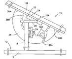
- FIG. 1is an elevational assembly view of the invention.
- FIG. 2Ais a top view of the base “H” frame and FIG. 2B is a view of the channel support.
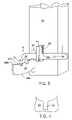
- FIG. 3is a view of details of the detente.
- FIG. 4shows details of the notches.
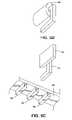
- FIG. 5Ais an assembly view
- FIG. 5Bis an exploded view showing a construction of a seat with a seat attachment bar that telescopes into one of an row of square tubes.
- FIG. 5Cshows a row of square tubes, mounted on the underside of the pad and the seat with seat attachment 44 poised for insertion into one of the tubes.
- FIG. 5Dshows a (padded) toe bar that can be very conveniently substituted for the seat.
- FIG. 1is a side view showing the exercise bench 10 of this invention.
- a base being a “H” frame 12is shown to better advantage by the top view of FIG. 2 as being a pair of horizontal beams 14 connected by connecting beam 16 .
- a vertical support post 18 shown in phantom in FIG. 2Ahas a lower end secured to and extending from the connecting beam 16 .
- the upper end of the support post 18is joined to one end of a horizontal channel 20 .
- the upper end of the support post 18is jpoined by a hinging member to a bench member.
- the bench membercomrises a panel 24 having a bottom surface facing the H frame 12 and an opposie surface interfacing flush against pad 26 . In use, the user lies on the pad 26 .
- the hinging membercomprises one section being a channel 20 (shown in FIG. 2B ) and another section being a bar 22 .
- the channel 20comprises two parallel side panels 20 A joined by a hinging panel 20 B.
- the joining panel of channel 20is mounted on top of support post 18 and the other hinging section, being bar 22 , is secured flush against the bottom surface of the panel 24 .
- the bar 22is hingeably secured to the channel 20 by a hinging pin 22 A such that the bar 22 nests between the two parallel sides on the joining side of the channel when the bench member is horizontal.
- This structurepermits tilting the pad 26 from a horizontal orientation to a vertical orientation.
- a flat plate 28having a broadest surface bounded by a major arcuate edge 28 A concentric with and larger than a minor arcuate edge 28 B and a pair of end edges 30 A,B between ends of the major and minor arcuate edges 28 A,B.
- the end edges 28 A,Bare secured to the bottom surface of the panel 24 such that the plate 28 extends toward the H frame 12 away from the bench member.
- the plate 28has a row of square notches 31 cut in the minor arc, arcuate edge 28 .
- the notches 31function as “catches” for a lever 34 that is pivotally mounted on the side of support beam 18 .
- the lever 34pivots about pin 36 mounted on the side of support post 18 and is biased by spring 38 to engage a selected one of the notches 31 .
- the springis retained in a keeper 39 supported on the side of the support post 18 .
- the springis thereby compressed by the lever 34 on one end 38 A of the spring 38 and the keeper 39 on the other end of the spring 38 so as to force the lever 34 to engage the notch 31 F. Selection of the notch 31 establishes the selected angle of tilt according to the requirement of the user.
- the lever 34is disengaged from the notch 30 by depressing the lever 34 on one end with force F or lifting the opposite end with force G so as to disengage the lever from the notches and permit the user to change the angle of tilt.
- lever arrangement of the present inventioncompared to the popit arrangement of the prior art is that the present invention permits disengagement by pressing on the lever rather than pulling on a pin as required by the posit pin of the prior art.
- the levercan fit tightly into the notch causing a tight lockup of the mechanism yet can be easily removed with leverage force not present on the standard straight pull popit pin.
- the levercan be operated from either side of the bench using the toe to depress one end of the lever or lifting the other end of the lever. Therefore there is no need for the user to bend over making the operation more convenient and faster than the prior art.
- An overall advantageis that, the lever arrangement does not encounter the sticking problem inherent in the popit type of catch.
- FIG. 4shows another advantage of the notch construction wherein the notch can have inherently a deeper engagement than can be had with a hole in a plate which is limited by the thickness of the plate.
- Another advantage of the notch constructionwhich is an embodiment of the invention, is that the individual notches 31 have tapered sides so that the lever can “seek” alignment with the notch.
- the keeper 39 over the spring and leveris provided with a set screw 41 through the housing abutting the lever.
- the set screwlimits lateral movement of the lever which develops through use and ensures a tight lock of the arcuate curved bar 28 by engaging the flat surface of the bar as an adjustable stop.
- the “tightness” (resistance to turn) of the lever 34is adjustable by tightening or loosening the set screw 41 against the lever 34 .
- FIG. 5Ais an assembly view
- FIG. 5Bis an exploded view showing a construction of a seat 42 with a seat attachment 44 that telescopes into one of a row of square tubes 46 attached to an underside of pad 24 .
- FIG. 5Cshows to best, advantage, the row of square tubes 46 , mounted on the underside of the pad 24 together with the seat 43 with seat attachment 44 poised for insertion into one of the tubes 46.
- FIG. 5Dshows a (padded) toe bar 48 that can be very conveniently substituted for the seat 43 .
- back extensionscan be performed by locating the padded toe bar 48 in a tube close to the center of the pad 24 , and hooking the heel or heels to the padded bar 48 , and extending out over the far end of the pad.
- Effectiveness of performing the back extensions and situpsis enhanced by holding dumbbells while performing the back extensions and situps.
- Another advantageis that the user disengages the lever by pushing rather than by pulling and is thereby enable to exert greater force.
- the two parallel bars 22affixed to one end of column 18 and providing the hinge point 22 A extending out past the (cantilevered) side wall of column 18 allowing the bench pad support bar 24 to pivot to a position parallel to a column 18 while serving as a horizontal alignment stabilizer for bar 24 when rotated back to the horizontal position.
- a bar attachable to the bench and securing the legs of the userare provided that secure the user's legs while he is performing situps.
Landscapes
- Health & Medical Sciences (AREA)
- Life Sciences & Earth Sciences (AREA)
- Biophysics (AREA)
- Orthopedic Medicine & Surgery (AREA)
- General Health & Medical Sciences (AREA)
- Physical Education & Sports Medicine (AREA)
- Special Chairs (AREA)
Abstract
Description
Claims (13)
Priority Applications (1)
| Application Number | Priority Date | Filing Date | Title |
|---|---|---|---|
| US10/286,519US6994661B1 (en) | 2002-11-01 | 2002-11-01 | Tiltable exercise bench |
Applications Claiming Priority (1)
| Application Number | Priority Date | Filing Date | Title |
|---|---|---|---|
| US10/286,519US6994661B1 (en) | 2002-11-01 | 2002-11-01 | Tiltable exercise bench |
Publications (1)
| Publication Number | Publication Date |
|---|---|
| US6994661B1true US6994661B1 (en) | 2006-02-07 |
Family
ID=35734155
Family Applications (1)
| Application Number | Title | Priority Date | Filing Date |
|---|---|---|---|
| US10/286,519Expired - LifetimeUS6994661B1 (en) | 2002-11-01 | 2002-11-01 | Tiltable exercise bench |
Country Status (1)
| Country | Link |
|---|---|
| US (1) | US6994661B1 (en) |
Cited By (8)
| Publication number | Priority date | Publication date | Assignee | Title |
|---|---|---|---|---|
| US20090305856A1 (en)* | 2004-11-29 | 2009-12-10 | Raffaele Martini Pandozy | Abdominal exercising apparatus and method |
| US9233277B1 (en)* | 2012-04-13 | 2016-01-12 | Mark A. Krull | Exercise bench methods and apparatus |
| CN109908544A (en)* | 2019-04-23 | 2019-06-21 | 王滨 | A kind of Multifunctional fitness stool |
| RU203449U1 (en)* | 2020-11-10 | 2021-04-06 | Федеральное государственное автономное образовательное учреждение высшего образования «Южно-Уральский государственный университет (национальный исследовательский университет)» ФГАОУ ВО «ЮУрГУ (НИУ)» | Upper Row Exerciser Bench |
| WO2023177925A1 (en)* | 2022-03-18 | 2023-09-21 | Todd Evan Dickerson | Pushup and planking exercise device |
| US12042688B1 (en) | 2021-02-14 | 2024-07-23 | Gym-In-A-Box Llc | Versatile compact universal gym with door or doors |
| USD1059511S1 (en) | 2020-10-09 | 2025-01-28 | Gym-In-A-Box Llc | Frame for a versatile universal gym |
| US12280289B2 (en) | 2018-04-11 | 2025-04-22 | Gym-In-A-Box Llc | Versatile universal gym |
Citations (11)
| Publication number | Priority date | Publication date | Assignee | Title |
|---|---|---|---|---|
| US194477A (en)* | 1877-08-21 | Improvement in invalid-chairs | ||
| US425153A (en)* | 1890-04-08 | Bush-hammer | ||
| US4546967A (en)* | 1983-01-25 | 1985-10-15 | Kecala Ihor G | Exercise bench |
| US4746114A (en)* | 1986-10-06 | 1988-05-24 | Bollinger Industries | Adjustable seat assembly for exercise apparatus |
| US5082259A (en)* | 1990-09-05 | 1992-01-21 | Karl Gonzalez | Weight lifting apparatus |
| USD406290S (en)* | 1998-01-21 | 1999-03-02 | Stamina Products, Inc. | Multi-purpose exercise bench |
| US6030324A (en)* | 1998-02-03 | 2000-02-29 | Stamina Products, Inc. | Multi-purpose exercise bench |
| US6106445A (en)* | 1996-07-19 | 2000-08-22 | Lay; Kenneth G. | Ergonomic, passive exercise chair with passive exercise headrest |
| US6287243B1 (en)* | 1999-02-22 | 2001-09-11 | Brunswick Corporation | Multi-adjustable exercise bench |
| US6468191B1 (en)* | 2001-07-11 | 2002-10-22 | Larry Cameron | Abdomen exercise bench |
| US6659923B2 (en)* | 2001-09-12 | 2003-12-09 | Pro Star Sports, Incorporated | Exercise bench with linearly adjustable carriage and convenient back and seat adjustments |
- 2002
- 2002-11-01USUS10/286,519patent/US6994661B1/ennot_activeExpired - Lifetime
Patent Citations (11)
| Publication number | Priority date | Publication date | Assignee | Title |
|---|---|---|---|---|
| US194477A (en)* | 1877-08-21 | Improvement in invalid-chairs | ||
| US425153A (en)* | 1890-04-08 | Bush-hammer | ||
| US4546967A (en)* | 1983-01-25 | 1985-10-15 | Kecala Ihor G | Exercise bench |
| US4746114A (en)* | 1986-10-06 | 1988-05-24 | Bollinger Industries | Adjustable seat assembly for exercise apparatus |
| US5082259A (en)* | 1990-09-05 | 1992-01-21 | Karl Gonzalez | Weight lifting apparatus |
| US6106445A (en)* | 1996-07-19 | 2000-08-22 | Lay; Kenneth G. | Ergonomic, passive exercise chair with passive exercise headrest |
| USD406290S (en)* | 1998-01-21 | 1999-03-02 | Stamina Products, Inc. | Multi-purpose exercise bench |
| US6030324A (en)* | 1998-02-03 | 2000-02-29 | Stamina Products, Inc. | Multi-purpose exercise bench |
| US6287243B1 (en)* | 1999-02-22 | 2001-09-11 | Brunswick Corporation | Multi-adjustable exercise bench |
| US6468191B1 (en)* | 2001-07-11 | 2002-10-22 | Larry Cameron | Abdomen exercise bench |
| US6659923B2 (en)* | 2001-09-12 | 2003-12-09 | Pro Star Sports, Incorporated | Exercise bench with linearly adjustable carriage and convenient back and seat adjustments |
Cited By (10)
| Publication number | Priority date | Publication date | Assignee | Title |
|---|---|---|---|---|
| US20090305856A1 (en)* | 2004-11-29 | 2009-12-10 | Raffaele Martini Pandozy | Abdominal exercising apparatus and method |
| US7691042B2 (en)* | 2004-11-29 | 2010-04-06 | Raffaele Martini Pandozy | Abdominal exercising apparatus and method |
| US9233277B1 (en)* | 2012-04-13 | 2016-01-12 | Mark A. Krull | Exercise bench methods and apparatus |
| US12280289B2 (en) | 2018-04-11 | 2025-04-22 | Gym-In-A-Box Llc | Versatile universal gym |
| CN109908544A (en)* | 2019-04-23 | 2019-06-21 | 王滨 | A kind of Multifunctional fitness stool |
| USD1059511S1 (en) | 2020-10-09 | 2025-01-28 | Gym-In-A-Box Llc | Frame for a versatile universal gym |
| RU203449U1 (en)* | 2020-11-10 | 2021-04-06 | Федеральное государственное автономное образовательное учреждение высшего образования «Южно-Уральский государственный университет (национальный исследовательский университет)» ФГАОУ ВО «ЮУрГУ (НИУ)» | Upper Row Exerciser Bench |
| US12042688B1 (en) | 2021-02-14 | 2024-07-23 | Gym-In-A-Box Llc | Versatile compact universal gym with door or doors |
| WO2023177925A1 (en)* | 2022-03-18 | 2023-09-21 | Todd Evan Dickerson | Pushup and planking exercise device |
| US12364899B2 (en) | 2022-03-18 | 2025-07-22 | Todd Evan Dickerson | Pushup and planking exercise device |
Similar Documents
| Publication | Publication Date | Title |
|---|---|---|
| US9452308B2 (en) | Exercise device | |
| US5997450A (en) | Combination slant board and abdominal rocker | |
| JP4508868B2 (en) | Exercise equipment | |
| US9993681B2 (en) | Core training bench | |
| US5865710A (en) | Step aerobic platform | |
| EP2029245B1 (en) | Stackable exercise chair | |
| US4566691A (en) | Exercise bench | |
| US7674216B1 (en) | Fitness apparatus | |
| US4618144A (en) | Portable exercise device | |
| US5350346A (en) | Weight bench with slidable seat construction | |
| US7081073B1 (en) | Foot retaining device for inversion exerciser | |
| US7806812B2 (en) | Foldable exercise device | |
| US6273834B1 (en) | Quick-release self-adjusting latch for adjustable basketball goal assembly | |
| US20250161742A1 (en) | Multi-function exercise apparatus | |
| JP2008220978A (en) | Collapsible exerciser | |
| US6422957B1 (en) | Quick-release self-adjusting slide collar mechanism for height adjustment of a basketball apparatus | |
| JPS62170267A (en) | Body training apparatus | |
| WO2007148333A2 (en) | Compact office exercise unit | |
| US11724146B2 (en) | Exercise equipment and method of using the same | |
| US6994661B1 (en) | Tiltable exercise bench | |
| US11700947B1 (en) | Convertible support assembly | |
| GB2185416A (en) | Exercise bench | |
| KR200315439Y1 (en) | Multipurpose fitness equipment | |
| JP3099716U (en) | Exercise equipment | |
| CA2603283A1 (en) | Collapsible exerciser |
Legal Events
| Date | Code | Title | Description |
|---|---|---|---|
| AS | Assignment | Owner name:DAWSON, MATTHEW F., WASHINGTON Free format text:ASSIGNMENT OF ASSIGNORS INTEREST;ASSIGNOR:DAWSON, FRED;REEL/FRAME:018047/0323 Effective date:20060715 | |
| REMI | Maintenance fee reminder mailed | ||
| FEPP | Fee payment procedure | Free format text:PETITION RELATED TO MAINTENANCE FEES GRANTED (ORIGINAL EVENT CODE: PMFG); ENTITY STATUS OF PATENT OWNER: SMALL ENTITY Free format text:PETITION RELATED TO MAINTENANCE FEES FILED (ORIGINAL EVENT CODE: PMFP); ENTITY STATUS OF PATENT OWNER: SMALL ENTITY | |
| REIN | Reinstatement after maintenance fee payment confirmed | ||
| FP | Lapsed due to failure to pay maintenance fee | Effective date:20100207 | |
| PRDP | Patent reinstated due to the acceptance of a late maintenance fee | Effective date:20100901 | |
| FPAY | Fee payment | Year of fee payment:4 | |
| SULP | Surcharge for late payment | ||
| REMI | Maintenance fee reminder mailed | ||
| LAPS | Lapse for failure to pay maintenance fees | ||
| FP | Lapsed due to failure to pay maintenance fee | Effective date:20140207 | |
| FEPP | Fee payment procedure | Free format text:PETITION RELATED TO MAINTENANCE FEES DISMISSED (ORIGINAL EVENT CODE: PMFS); ENTITY STATUS OF PATENT OWNER: SMALL ENTITY | |
| FEPP | Fee payment procedure | Free format text:PETITION RELATED TO MAINTENANCE FEES FILED (ORIGINAL EVENT CODE: PMFP); ENTITY STATUS OF PATENT OWNER: SMALL ENTITY | |
| FEPP | Fee payment procedure | Free format text:PETITION RELATED TO MAINTENANCE FEES FILED (ORIGINAL EVENT CODE: PMFP); ENTITY STATUS OF PATENT OWNER: SMALL ENTITY | |
| PRDP | Patent reinstated due to the acceptance of a late maintenance fee | Effective date:20181127 | |
| FEPP | Fee payment procedure | Free format text:PETITION RELATED TO MAINTENANCE FEES GRANTED (ORIGINAL EVENT CODE: PMFG); ENTITY STATUS OF PATENT OWNER: SMALL ENTITY Free format text:PETITION RELATED TO MAINTENANCE FEES DISMISSED (ORIGINAL EVENT CODE: PMFS); ENTITY STATUS OF PATENT OWNER: SMALL ENTITY | |
| FEPP | Fee payment procedure | Free format text:PETITION RELATED TO MAINTENANCE FEES FILED (ORIGINAL EVENT CODE: PMFP); ENTITY STATUS OF PATENT OWNER: SMALL ENTITY | |
| FEPP | Fee payment procedure | Free format text:PETITION RELATED TO MAINTENANCE FEES GRANTED (ORIGINAL EVENT CODE: PMFG); ENTITY STATUS OF PATENT OWNER: SMALL ENTITY Free format text:SURCHARGE, PETITION TO ACCEPT PYMT AFTER EXP, UNINTENTIONAL. (ORIGINAL EVENT CODE: M2558); ENTITY STATUS OF PATENT OWNER: SMALL ENTITY | |
| MAFP | Maintenance fee payment | Free format text:PAYMENT OF MAINTENANCE FEE, 8TH YR, SMALL ENTITY (ORIGINAL EVENT CODE: M2552); ENTITY STATUS OF PATENT OWNER: SMALL ENTITY Year of fee payment:8 Free format text:PAYMENT OF MAINTENANCE FEE, 12TH YR, SMALL ENTITY (ORIGINAL EVENT CODE: M2553); ENTITY STATUS OF PATENT OWNER: SMALL ENTITY Year of fee payment:12 | |
| PRDP | Patent reinstated due to the acceptance of a late maintenance fee | Effective date:20190304 | |
| STCF | Information on status: patent grant | Free format text:PATENTED CASE |