US6994615B2 - Cutting tools with two-slope profile - Google Patents
Cutting tools with two-slope profileDownload PDFInfo
- Publication number
- US6994615B2 US6994615B2US10/455,008US45500803AUS6994615B2US 6994615 B2US6994615 B2US 6994615B2US 45500803 AUS45500803 AUS 45500803AUS 6994615 B2US6994615 B2US 6994615B2
- Authority
- US
- United States
- Prior art keywords
- annular face
- periphery
- face
- inner face
- horizontal
- Prior art date
- Legal status (The legal status is an assumption and is not a legal conclusion. Google has not performed a legal analysis and makes no representation as to the accuracy of the status listed.)
- Expired - Lifetime
Links
- 238000005520cutting processMethods0.000titleclaimsabstractdescription23
- 239000000758substrateSubstances0.000claimsabstractdescription38
- 229910003460diamondInorganic materials0.000claimsdescription31
- 239000010432diamondSubstances0.000claimsdescription31
- 238000000034methodMethods0.000claimsdescription29
- 229910052751metalInorganic materials0.000claimsdescription20
- 239000002184metalSubstances0.000claimsdescription20
- 229910052582BNInorganic materials0.000claimsdescription19
- PZNSFCLAULLKQX-UHFFFAOYSA-NBoron nitrideChemical compoundN#BPZNSFCLAULLKQX-UHFFFAOYSA-N0.000claimsdescription19
- 229910052984zinc sulfideInorganic materials0.000claimsdescription9
- 150000001247metal acetylidesChemical class0.000claimsdescription6
- 239000002245particleSubstances0.000description12
- 239000000463materialSubstances0.000description9
- 239000002131composite materialSubstances0.000description7
- UONOETXJSWQNOL-UHFFFAOYSA-Ntungsten carbideChemical compound[W+]#[C-]UONOETXJSWQNOL-UHFFFAOYSA-N0.000description5
- 238000005553drillingMethods0.000description4
- 239000010955niobiumSubstances0.000description3
- 238000012360testing methodMethods0.000description3
- XEEYBQQBJWHFJM-UHFFFAOYSA-NIronChemical compound[Fe]XEEYBQQBJWHFJM-UHFFFAOYSA-N0.000description2
- PXHVJJICTQNCMI-UHFFFAOYSA-NNickelChemical compound[Ni]PXHVJJICTQNCMI-UHFFFAOYSA-N0.000description2
- 238000004458analytical methodMethods0.000description2
- 239000011230binding agentSubstances0.000description2
- 238000005229chemical vapour depositionMethods0.000description2
- 238000001816coolingMethods0.000description2
- 239000010438graniteSubstances0.000description2
- 238000000227grindingMethods0.000description2
- 239000000203mixtureSubstances0.000description2
- 229910052758niobiumInorganic materials0.000description2
- GUCVJGMIXFAOAE-UHFFFAOYSA-Nniobium atomChemical compound[Nb]GUCVJGMIXFAOAE-UHFFFAOYSA-N0.000description2
- 239000000126substanceSubstances0.000description2
- 229910052715tantalumInorganic materials0.000description2
- GUVRBAGPIYLISA-UHFFFAOYSA-Ntantalum atomChemical compound[Ta]GUVRBAGPIYLISA-UHFFFAOYSA-N0.000description2
- 239000010936titaniumSubstances0.000description2
- WFKWXMTUELFFGS-UHFFFAOYSA-NtungstenChemical compound[W]WFKWXMTUELFFGS-UHFFFAOYSA-N0.000description2
- 229910052721tungstenInorganic materials0.000description2
- 239000010937tungstenSubstances0.000description2
- ZOKXTWBITQBERF-UHFFFAOYSA-NMolybdenumChemical compound[Mo]ZOKXTWBITQBERF-UHFFFAOYSA-N0.000description1
- 229910000831SteelInorganic materials0.000description1
- RTAQQCXQSZGOHL-UHFFFAOYSA-NTitaniumChemical compound[Ti]RTAQQCXQSZGOHL-UHFFFAOYSA-N0.000description1
- -1VIB metalsChemical class0.000description1
- 238000005299abrasionMethods0.000description1
- 239000003082abrasive agentSubstances0.000description1
- 239000000956alloySubstances0.000description1
- 229910045601alloyInorganic materials0.000description1
- 230000015572biosynthetic processEffects0.000description1
- 239000003054catalystSubstances0.000description1
- 239000011248coating agentSubstances0.000description1
- 238000000576coating methodMethods0.000description1
- 239000010941cobaltSubstances0.000description1
- 229910017052cobaltInorganic materials0.000description1
- GUTLYIVDDKVIGB-UHFFFAOYSA-Ncobalt atomChemical compound[Co]GUTLYIVDDKVIGB-UHFFFAOYSA-N0.000description1
- 239000012809cooling fluidSubstances0.000description1
- 239000013078crystalSubstances0.000description1
- 230000032798delaminationEffects0.000description1
- 230000001419dependent effectEffects0.000description1
- 230000009977dual effectEffects0.000description1
- 230000000694effectsEffects0.000description1
- 238000005530etchingMethods0.000description1
- 229910052735hafniumInorganic materials0.000description1
- VBJZVLUMGGDVMO-UHFFFAOYSA-Nhafnium atomChemical compound[Hf]VBJZVLUMGGDVMO-UHFFFAOYSA-N0.000description1
- 238000010438heat treatmentMethods0.000description1
- 238000009863impact testMethods0.000description1
- 230000006872improvementEffects0.000description1
- 229910052742ironInorganic materials0.000description1
- 238000003754machiningMethods0.000description1
- 238000004519manufacturing processMethods0.000description1
- 150000002739metalsChemical class0.000description1
- 238000003801millingMethods0.000description1
- 238000012986modificationMethods0.000description1
- 230000004048modificationEffects0.000description1
- 229910052750molybdenumInorganic materials0.000description1
- 239000011733molybdenumSubstances0.000description1
- 229910052759nickelInorganic materials0.000description1
- 230000000704physical effectEffects0.000description1
- 230000008569processEffects0.000description1
- 230000009467reductionEffects0.000description1
- 239000011435rockSubstances0.000description1
- VSZWPYCFIRKVQL-UHFFFAOYSA-Nselanylidenegallium;seleniumChemical compound[Se].[Se]=[Ga].[Se]=[Ga]VSZWPYCFIRKVQL-UHFFFAOYSA-N0.000description1
- 239000007787solidSubstances0.000description1
- 239000010959steelSubstances0.000description1
- 229910052719titaniumInorganic materials0.000description1
- LEONUFNNVUYDNQ-UHFFFAOYSA-Nvanadium atomChemical compound[V]LEONUFNNVUYDNQ-UHFFFAOYSA-N0.000description1
Images


Classifications
- E—FIXED CONSTRUCTIONS
- E21—EARTH OR ROCK DRILLING; MINING
- E21B—EARTH OR ROCK DRILLING; OBTAINING OIL, GAS, WATER, SOLUBLE OR MELTABLE MATERIALS OR A SLURRY OF MINERALS FROM WELLS
- E21B10/00—Drill bits
- E21B10/46—Drill bits characterised by wear resisting parts, e.g. diamond inserts
- E21B10/56—Button-type inserts
- E21B10/567—Button-type inserts with preformed cutting elements mounted on a distinct support, e.g. polycrystalline inserts
- E21B10/573—Button-type inserts with preformed cutting elements mounted on a distinct support, e.g. polycrystalline inserts characterised by support details, e.g. the substrate construction or the interface between the substrate and the cutting element
- E21B10/5735—Interface between the substrate and the cutting element
Definitions
- the present inventionrelates to the field of abrasive tool inserts.
- An abrasive particle compactis a polycrystalline mass of abrasive particles, such as diamond and/or cubic boron nitride (CBN), bonded together to form an integral, tough, high-strength mass.
- abrasive particlessuch as diamond and/or cubic boron nitride (CBN)
- CBNcubic boron nitride
- Such componentscan be bonded together in a particle-to-particle self-bonded relationship, by means of a bonding medium disposed between the particles, or by combinations thereof.
- the abrasive particle content of the abrasive compactis high and there is an extensive amount of direct particle-to-particle bonding.
- Abrasive compactsare made under elevated or high pressure and temperature (HP/HT) conditions at which the particles, diamond or CBN, are crystallographically stable.
- HP/HThigh pressure and temperature
- a supported abrasive particle compactherein termed a composite compact, is an abrasive particle compact, which is bonded to a substrate material, such as cemented tungsten carbide.
- Abrasive compactstend to be brittle and, in use, they frequently are supported by being bonded to a cemented carbide substrate. Such supported abrasive compacts are known in the art as composite abrasive compacts. Compacts of this type are described, for example, in U.S. Pat. Nos. 3,743,489, 3,745,623, and 3,767,371. The bond to the support can be formed either during or subsequent to the formation of the abrasive particle compact. Composite abrasive compacts may be used as such in the working surface of an abrasive tool.
- Drill bits for use in rock drilling, machining of wear resistant materials, and other operations which require high abrasion resistance or wear resistancegenerally consist of a plurality of polycrystalline abrasive cutting elements fixed in a holder.
- U.S. Pat. No. 4,109,737describes drill bits with a tungsten carbide stud (substrate) having a polycrystalline diamond compact on the outer surface of the cutting element. A plurality of these cutting elements then are mounted generally by interference fit into recesses into the crown of a drill bit, such as a rotary drill bit.
- These drill bitsgenerally have means for providing water-cooling or other cooling fluids to the interface between the drill crown and the substance being drilled during drilling operations.
- the cutting elementcomprises an elongated pin of a metal carbide (stud) which may be either sintered or cemented carbide (such as tungsten carbide) with an abrasive particle compact (e.g., polycrystalline diamond) at one end of the pin for form a composite compact.
- a metal carbidestud
- abrasive particle compacte.g., polycrystalline diamond
- Fabrication of the composite compacttypically is achieved by placing a cemented carbide substrate into the container of a press. A mixture of diamond grains or diamond grains and catalyst binder is placed atop the substrate and compressed under HP/HT conditions.
- a composite compact formed in the above-described mannermay be subject to a number of shortcomings. For example, the coefficients of thermal expansion and elastic constants of cemented carbide and diamond are close, but not exactly the same. Thus, during heating or cooling of the polycrystalline diamond compact (PDC), thermally induced stresses occur at the interface between the diamond layer and the cemented carbide substrate, the magnitude of these stresses being dependent, for example, on the disparity in thermal expansion coefficients and elastic constants.
- PDCpolycrystalline diamond compact
- Another potential shortcomingrelates to the creation of internal stresses within the diamond layer, which can result in a fracturing of that layer. Such stresses also result from the presence of the cemented carbide substrate and are distributed according to the size, geometry, and physical properties of the cemented carbide substrate and the polycrystalline diamond layer.
- the toolsare subject to delamination failures caused by thermally induced axial residual stresses on the outer diameter of the superabrasive layer. The stresses reduce the effectiveness of the tools and limit the applications in which they can be used.
- U.S. Pat. No. 5,486,137also proposes a tool insert having an outer downwardly sloped interface surface.
- U.S. Pat. No. 5,494,477proposes a tool insert having an outer downwardly sloping interface.
- U.S. Pat. No. 5,971,087also proposes various dual and triple slope interface profiles.
- the inventionrelates to an abrasive tool insert formed from a substrate having an inner face that has a center, and annular face which annular face has a periphery.
- the inner faceslopes outwardly and downwardly from the center at an angle ranging from between about 5° and 30° from the horizontal.
- the annular facesurrounds by the inner face and terminates at the periphery.
- the annular faceslopes downwardly and outwardly from the inner face at an angle of between about 20° and 75° from the horizontal.
- a continuous abrasive layer, having a center and a periphery forming a cutting edge,is integrally formed on the substrate and defines an interface therebetween.
- the inventionfurther relates to a method for forming an abrasive tool insert, which commences with providing a substrate having an inner face that has a center, and annular face which annular face has a periphery.
- the inner faceslopes outwardly and downwardly from the center at an angle ranging from between about 5° and 30° from the horizontal.
- the annular facesurrounds by the inner face and terminates at the periphery.
- the annular faceslopes downwardly and outwardly from the inner face at an angle of between about 20° and 75° from the horizontal.
- a continuous abrasive layerhaving a center and a periphery forming a cutting edge, is integrally formed on the substrate and defines an interface therebetween.
- FIG. 1is a perspective view of one embodiment of the interface configuration of the present invention
- FIG. 2is a cross-sectional elevational view of the substrate of FIG. 1 ;
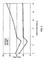
- FIG. 3graphically displays the stress (MPa) versus inner face angle for a cutter element having the profile as depicted in FIG. 2 ;
- Applicantshave found a unique geometry for cutters, wherein a sloped profile is incorporated in the interior of the cutter.
- the sloped profileis combined with a steeper slope on the outer edge of the cutter, further reduces the surface residual stresses.
- the inventive cutterhas an increased useful life with the reduced thermally induced residual radial and axial stresses in the abrasive layer. In another embodiment, the inventive cutter demonstrates increased impact performance and extended working life.
- the carbide supportcontains 2 distinctive faces of support for the abrasive material, each face being disposed at an angle (relative to the horizontal) so as to optimized (minimize) radial stress and axial stress.
- a cutter, 10is formed from a lower support, 12 , and an upper abrasive layer, 14 (see FIG. 2 ).
- Support 12has a central, inner face, 16 , that extends outwardly and downwardly from an apex or center, 18 .
- Surrounding face 18is an outer annular face, 20 , that extends outwardly and downwardly from the outer periphery of face 16 .
- a slight ledge, 22surrounds the outer periphery of annular face 20 .
- Superimposed on inner face 16can be saw tooth annuli and troughs, such as are disclosed in U.S. Pat. No. 6,315,652.
- outer annular face 20slopes downwardly from the horizontal at an angle of between about 20° and 75°. In another embodiment, outer annular face slopes downwardly at an angle of about 45°. In another embodiment to optimize (minimize) axial stress, inner face 16 slopes downwardly from the horizontal at an angle of between about 5° and 30°. In yet another embodiment, inner face 16 slopes downwardly at an angle of 7.5°.
- the outer surface configuration of the diamond (upper abrasive) layer 14is not critical.
- the surface configuration of the diamond layermay be in the form of hemispherical, planar, conical, reduced or increased radius, chisel, or non-axisymmetric in shape.
- all forms of tungsten carbide inserts used in the drilling industrymay be enhanced by the addition of a diamond layer, and in one embodiment is further improved by the current invention by addition of a pattern of ridges.
- the cuttermay be manufactured, in one embodiment by fabricating a cemented carbide substrate 12 in a generally cylindrical shape.
- the cemented metal carbide substrateis conventional in composition and, thus, may be include any of the Group IVB, VB, or VIB metals, which are pressed and sintered in the presence of a binder of cobalt, nickel or iron, or alloys thereof. Examples include carbides of tungsten (W), niobium (Nb), zirconium (Zr), vanadium (V), tantalum (Ta), titanium (Ti), and hafnium (Hf).
- the metal carbideis tungsten carbide.
- the end face(s) on the carbide substrateare formed by any suitable cutting, grinding, stamping, or etching process.
- the upper layeris polycrystalline diamond (PCD).
- the upper abrasive layer 14comprises at least one of synthetic and natural diamond, cubic boron nitride (CBN), wurtzite boron nitride, combinations thereof, and like materials.
- the polycrystalline material layer 14 and the substrate 12are subjected to pressures and temperatures sufficient to effect intercrystalline bonding in the polycrystalline material, and create a solid polycrystalline material layer 14 .
- chemical vapor depositionmay also be used to deposit the polycrystalline material on the substrate 12 . This is accomplished by coating the particles of the individual diamond crystals with various metals such as tungsten, tantalum, niobium, or molybdenum, and the like by chemical vapor techniques using fluidized bed procedure. Chemical vapor deposition techniques are also known in the art which utilize plasma assisted or heated filament methods.
- the inventionrelates particularly to tool inserts having a support with a central downwardly sloping profile and an outer steeper sloping profile, which reduces the surface axial residual stresses by 83% compared to a flat, planar interface and by 23% compared to a substrate with a single sloped rim.
- the reduction of the surface axial residual stressincreases the impact performance and extends the working lifetime of the cutting tool.
- Applicantshave performed finite element analysis (FEA) of the inventive cutter versus the prior art polycrystalline diamond cutters, one having a flat interface and one having a single slope interface for a cutting tool with 19 mm diameter, 16 mm overall height, and 3 mm diamond table thickness.
- FEAfinite element analysis
- the outer annular facehad an angle of 45° with respect to the horizontal, while the inner face angle varied between about 0° and 30° from the horizontal.
- the cutting tool insertis manufactured by conventional high pressure/high temperature (HP/HT) techniques well known in the art. Such techniques are disclosed, inter alia, in the art cited above.
- HP/HThigh pressure/high temperature
- the inventive cutteris compared to a single slope tool insert of the prior art.
- the performance of the cutter on a chamfer pieceis measured, with each piece having a carbide chamfer of greater than about 0.2 mm, less than 1.0 mm radial or 45° on the locating base.
- the cutter (0.010′′ chamfered edge) sampleis mounted in a steel holder, with Rake angle to work piece 7 deg radial/12 degrees axial.
- the cutteris rotated and cuts in an interrupted fashion at a depth of 0.150′′ and transverse distance of 0.010′′ through a granite work piece at a cutting speed of 320 rpm and feed rate of about 3′′ per min. (7.62 cm/min).
- the testis stopped when the diamond table fails, and the number of impacts (entries into the block) counted.
- the inventive cuttershows unexpected improvement in impact resistance, with a count of 12600 as opposed to 11500 for the cutter of the prior art.
Landscapes
- Engineering & Computer Science (AREA)
- Life Sciences & Earth Sciences (AREA)
- Mining & Mineral Resources (AREA)
- Geology (AREA)
- Mechanical Engineering (AREA)
- Physics & Mathematics (AREA)
- Environmental & Geological Engineering (AREA)
- Fluid Mechanics (AREA)
- Chemical & Material Sciences (AREA)
- Crystallography & Structural Chemistry (AREA)
- General Life Sciences & Earth Sciences (AREA)
- Geochemistry & Mineralogy (AREA)
- Polishing Bodies And Polishing Tools (AREA)
Abstract
Description
| TABLE 1 | |||
| (1) Flat | (2) Single Sloped | (3) Double Sloped | |
| Stress in MPa | Interface | Interface, 45° | Interface, 10° and 45° |
| Maximum surface | 595 | 132 | 102 |
| tensile axial stress | |||
| Maximum surface | 300 | 160 | 151 |
| tensile radial | |||
| stress | |||
| Maximum surface | 88 | 0 | 0 |
| tensile hoop stress | |||
Claims (35)
Priority Applications (2)
| Application Number | Priority Date | Filing Date | Title |
|---|---|---|---|
| US10/455,008US6994615B2 (en) | 2002-07-10 | 2003-06-05 | Cutting tools with two-slope profile |
| US11/082,487US7097551B2 (en) | 2002-07-10 | 2005-03-17 | Cutting tools with two-slope profile |
Applications Claiming Priority (2)
| Application Number | Priority Date | Filing Date | Title |
|---|---|---|---|
| US39518102P | 2002-07-10 | 2002-07-10 | |
| US10/455,008US6994615B2 (en) | 2002-07-10 | 2003-06-05 | Cutting tools with two-slope profile |
Related Child Applications (1)
| Application Number | Title | Priority Date | Filing Date |
|---|---|---|---|
| US11/082,487ContinuationUS7097551B2 (en) | 2002-07-10 | 2005-03-17 | Cutting tools with two-slope profile |
Publications (2)
| Publication Number | Publication Date |
|---|---|
| US20040067724A1 US20040067724A1 (en) | 2004-04-08 |
| US6994615B2true US6994615B2 (en) | 2006-02-07 |
Family
ID=32045164
Family Applications (2)
| Application Number | Title | Priority Date | Filing Date |
|---|---|---|---|
| US10/455,008Expired - LifetimeUS6994615B2 (en) | 2002-07-10 | 2003-06-05 | Cutting tools with two-slope profile |
| US11/082,487Expired - LifetimeUS7097551B2 (en) | 2002-07-10 | 2005-03-17 | Cutting tools with two-slope profile |
Family Applications After (1)
| Application Number | Title | Priority Date | Filing Date |
|---|---|---|---|
| US11/082,487Expired - LifetimeUS7097551B2 (en) | 2002-07-10 | 2005-03-17 | Cutting tools with two-slope profile |
Country Status (1)
| Country | Link |
|---|---|
| US (2) | US6994615B2 (en) |
Cited By (4)
| Publication number | Priority date | Publication date | Assignee | Title |
|---|---|---|---|---|
| KR100795370B1 (en) | 2006-10-24 | 2008-01-17 | 일진다이아몬드(주) | Polycrystalline Diamond Compact |
| US20090012542A1 (en)* | 2007-07-03 | 2009-01-08 | Synecor, Llc | Satiation devices and methods for controlling obesity |
| US9069033B2 (en) | 2013-03-26 | 2015-06-30 | Industrial Technology Research Institute | 3-axis magnetic field sensor, method for fabricating magnetic field sensing structure and magnetic field sensing circuit |
| US20150233424A1 (en)* | 2013-05-22 | 2015-08-20 | Us Synthetic Corporation | Bearing assemblies including thick superhard tables and/or selected exposures, bearing apparatuses, and methods of use |
Families Citing this family (1)
| Publication number | Priority date | Publication date | Assignee | Title |
|---|---|---|---|---|
| JP1749454S (en)* | 2022-09-28 | 2023-07-27 | cutting insert |
Citations (20)
| Publication number | Priority date | Publication date | Assignee | Title |
|---|---|---|---|---|
| US3136615A (en) | 1960-10-03 | 1964-06-09 | Gen Electric | Compact of abrasive crystalline material with boron carbide bonding medium |
| US3141746A (en) | 1960-10-03 | 1964-07-21 | Gen Electric | Diamond compact abrasive |
| US3233988A (en) | 1964-05-19 | 1966-02-08 | Gen Electric | Cubic boron nitride compact and method for its production |
| US3743489A (en) | 1971-07-01 | 1973-07-03 | Gen Electric | Abrasive bodies of finely-divided cubic boron nitride crystals |
| US3745623A (en) | 1971-12-27 | 1973-07-17 | Gen Electric | Diamond tools for machining |
| US3767371A (en) | 1971-07-01 | 1973-10-23 | Gen Electric | Cubic boron nitride/sintered carbide abrasive bodies |
| US4109737A (en) | 1976-06-24 | 1978-08-29 | General Electric Company | Rotary drill bit |
| US5351772A (en) | 1993-02-10 | 1994-10-04 | Baker Hughes, Incorporated | Polycrystalline diamond cutting element |
| US5484330A (en) | 1993-07-21 | 1996-01-16 | General Electric Company | Abrasive tool insert |
| US5486137A (en)* | 1993-07-21 | 1996-01-23 | General Electric Company | Abrasive tool insert |
| US5494777A (en) | 1993-04-20 | 1996-02-27 | Japan Synthetic Rubber Co., Ltd. | Radiation sensitive resin composition |
| US5494477A (en)* | 1993-08-11 | 1996-02-27 | General Electric Company | Abrasive tool insert |
| US5743346A (en) | 1996-03-06 | 1998-04-28 | General Electric Company | Abrasive cutting element and drill bit |
| US5871060A (en)* | 1997-02-20 | 1999-02-16 | Jensen; Kenneth M. | Attachment geometry for non-planar drill inserts |
| US5971087A (en)* | 1998-05-20 | 1999-10-26 | Baker Hughes Incorporated | Reduced residual tensile stress superabrasive cutters for earth boring and drill bits so equipped |
| US6202771B1 (en)* | 1997-09-23 | 2001-03-20 | Baker Hughes Incorporated | Cutting element with controlled superabrasive contact area, drill bits so equipped |
| US6405814B1 (en)* | 1998-06-24 | 2002-06-18 | Smith International, Inc. | Cutting element with canted design for improved braze contact area |
| US6408959B2 (en)* | 1998-09-18 | 2002-06-25 | Kenneth E. Bertagnolli | Polycrystalline diamond compact cutter having a stress mitigating hoop at the periphery |
| US6527633B1 (en)* | 1998-07-06 | 2003-03-04 | Klaus Tank | Abrasive body |
| US20040009376A1 (en)* | 2002-07-10 | 2004-01-15 | Shan Wan | Abrasive tool inserts with diminished residual tensile stresses and their production |
Family Cites Families (2)
| Publication number | Priority date | Publication date | Assignee | Title |
|---|---|---|---|---|
| US5374854A (en) | 1992-07-08 | 1994-12-20 | Chen; Shih-Tsan | Automatic switch for controlling electric appliances |
| GB9412779D0 (en)* | 1994-06-24 | 1994-08-17 | Camco Drilling Group Ltd | Improvements in or relating to elements faced with superhard materials |
- 2003
- 2003-06-05USUS10/455,008patent/US6994615B2/ennot_activeExpired - Lifetime
- 2005
- 2005-03-17USUS11/082,487patent/US7097551B2/ennot_activeExpired - Lifetime
Patent Citations (20)
| Publication number | Priority date | Publication date | Assignee | Title |
|---|---|---|---|---|
| US3136615A (en) | 1960-10-03 | 1964-06-09 | Gen Electric | Compact of abrasive crystalline material with boron carbide bonding medium |
| US3141746A (en) | 1960-10-03 | 1964-07-21 | Gen Electric | Diamond compact abrasive |
| US3233988A (en) | 1964-05-19 | 1966-02-08 | Gen Electric | Cubic boron nitride compact and method for its production |
| US3743489A (en) | 1971-07-01 | 1973-07-03 | Gen Electric | Abrasive bodies of finely-divided cubic boron nitride crystals |
| US3767371A (en) | 1971-07-01 | 1973-10-23 | Gen Electric | Cubic boron nitride/sintered carbide abrasive bodies |
| US3745623A (en) | 1971-12-27 | 1973-07-17 | Gen Electric | Diamond tools for machining |
| US4109737A (en) | 1976-06-24 | 1978-08-29 | General Electric Company | Rotary drill bit |
| US5351772A (en) | 1993-02-10 | 1994-10-04 | Baker Hughes, Incorporated | Polycrystalline diamond cutting element |
| US5494777A (en) | 1993-04-20 | 1996-02-27 | Japan Synthetic Rubber Co., Ltd. | Radiation sensitive resin composition |
| US5486137A (en)* | 1993-07-21 | 1996-01-23 | General Electric Company | Abrasive tool insert |
| US5484330A (en) | 1993-07-21 | 1996-01-16 | General Electric Company | Abrasive tool insert |
| US5494477A (en)* | 1993-08-11 | 1996-02-27 | General Electric Company | Abrasive tool insert |
| US5743346A (en) | 1996-03-06 | 1998-04-28 | General Electric Company | Abrasive cutting element and drill bit |
| US5871060A (en)* | 1997-02-20 | 1999-02-16 | Jensen; Kenneth M. | Attachment geometry for non-planar drill inserts |
| US6202771B1 (en)* | 1997-09-23 | 2001-03-20 | Baker Hughes Incorporated | Cutting element with controlled superabrasive contact area, drill bits so equipped |
| US5971087A (en)* | 1998-05-20 | 1999-10-26 | Baker Hughes Incorporated | Reduced residual tensile stress superabrasive cutters for earth boring and drill bits so equipped |
| US6405814B1 (en)* | 1998-06-24 | 2002-06-18 | Smith International, Inc. | Cutting element with canted design for improved braze contact area |
| US6527633B1 (en)* | 1998-07-06 | 2003-03-04 | Klaus Tank | Abrasive body |
| US6408959B2 (en)* | 1998-09-18 | 2002-06-25 | Kenneth E. Bertagnolli | Polycrystalline diamond compact cutter having a stress mitigating hoop at the periphery |
| US20040009376A1 (en)* | 2002-07-10 | 2004-01-15 | Shan Wan | Abrasive tool inserts with diminished residual tensile stresses and their production |
Cited By (7)
| Publication number | Priority date | Publication date | Assignee | Title |
|---|---|---|---|---|
| KR100795370B1 (en) | 2006-10-24 | 2008-01-17 | 일진다이아몬드(주) | Polycrystalline Diamond Compact |
| US20090012542A1 (en)* | 2007-07-03 | 2009-01-08 | Synecor, Llc | Satiation devices and methods for controlling obesity |
| US9069033B2 (en) | 2013-03-26 | 2015-06-30 | Industrial Technology Research Institute | 3-axis magnetic field sensor, method for fabricating magnetic field sensing structure and magnetic field sensing circuit |
| US20150233424A1 (en)* | 2013-05-22 | 2015-08-20 | Us Synthetic Corporation | Bearing assemblies including thick superhard tables and/or selected exposures, bearing apparatuses, and methods of use |
| US9726222B2 (en)* | 2013-05-22 | 2017-08-08 | U.S. Synthetic Corporation | Bearing assemblies including thick superhard tables and/or selected exposures, bearing apparatuses, and methods of use |
| US10422379B2 (en)* | 2013-05-22 | 2019-09-24 | Us Synthetic Corporation | Bearing assemblies including thick superhard tables and/or selected exposures, bearing apparatuses, and methods of use |
| US11015649B2 (en) | 2013-05-22 | 2021-05-25 | Us Synthetic Corporation | Bearing assemblies including thick superhard tables and/or selected exposures, bearing apparatuses, and methods of use |
Also Published As
| Publication number | Publication date |
|---|---|
| US20050161035A1 (en) | 2005-07-28 |
| US20040067724A1 (en) | 2004-04-08 |
| US7097551B2 (en) | 2006-08-29 |
Similar Documents
| Publication | Publication Date | Title |
|---|---|---|
| US6933049B2 (en) | Abrasive tool inserts with diminished residual tensile stresses and their production | |
| EP1385662B1 (en) | Abrasive tool inserts and their production | |
| KR100783872B1 (en) | Manufacturing method of composite abrasive composite | |
| US6196910B1 (en) | Polycrystalline diamond compact cutter with improved cutting by preventing chip build up | |
| US6601662B2 (en) | Polycrystalline diamond cutters with working surfaces having varied wear resistance while maintaining impact strength | |
| US7568534B2 (en) | Dual-edge working surfaces for polycrystalline diamond cutting elements | |
| US8197936B2 (en) | Cutting structures | |
| US20170247949A1 (en) | Cutting elements, bearings, and earth-boring tools including multiple substrates attached to one another | |
| US20070186483A1 (en) | Composite abrasive compact | |
| EP1527251B1 (en) | Cutting tools with two-slope profile | |
| CN101336311A (en) | PCBN Cutting Tool Components | |
| EP0955445B1 (en) | Polycrystalline cutter element with specific interface | |
| US10233697B2 (en) | Methods of reducing stress in cutting elements for earth-boring tools and resulting cutting elements | |
| JP5394261B2 (en) | Substrate processing method | |
| US6994615B2 (en) | Cutting tools with two-slope profile | |
| US20160312542A1 (en) | Polycrystalline super hard construction & method of making |
Legal Events
| Date | Code | Title | Description |
|---|---|---|---|
| AS | Assignment | Owner name:GENERAL ELECTRIC COMPANY, NEW YORK Free format text:ASSIGNMENT OF ASSIGNORS INTEREST;ASSIGNORS:EASLEY, THOMAS CHARLES;WAN, SHAN;REEL/FRAME:014160/0898 Effective date:20030604 | |
| AS | Assignment | Owner name:GE SUPERABRASIVES, INC., CONNECTICUT Free format text:ASSIGNMENT OF ASSIGNORS INTEREST;ASSIGNOR:GENERAL ELECTRIC COMPANY;REEL/FRAME:015190/0560 Effective date:20031231 Owner name:DIAMOND INNOVATIONS, INC., OHIO Free format text:ASSIGNMENT OF ASSIGNORS INTEREST;ASSIGNOR:GE SUPERABRASIVES, INC.;REEL/FRAME:015147/0674 Effective date:20031231 | |
| AS | Assignment | Owner name:GE SUPERABRASIVES, INC., CONNECTICUT Free format text:CORRECTIVE DOCUMENT PREVIOUSLY RECORDED AT REEL 015190 FRAME 0560. (ASSIGNMENT OF ASSIGNOR'S INTEREST);ASSIGNOR:GENERAL ELECTRIC COMPANY;REEL/FRAME:015925/0001 Effective date:20031231 | |
| STCF | Information on status: patent grant | Free format text:PATENTED CASE | |
| FEPP | Fee payment procedure | Free format text:PAYOR NUMBER ASSIGNED (ORIGINAL EVENT CODE: ASPN); ENTITY STATUS OF PATENT OWNER: LARGE ENTITY | |
| FPAY | Fee payment | Year of fee payment:4 | |
| FPAY | Fee payment | Year of fee payment:8 | |
| FPAY | Fee payment | Year of fee payment:12 | |
| AS | Assignment | Owner name:UBS AG, STAMFORD BRANCH, CONNECTICUT Free format text:FIRST LIEN PATENT SECURITY AGREEMENT;ASSIGNOR:DIAMOND INNOVATIONS, INC.;REEL/FRAME:050272/0415 Effective date:20190828 Owner name:UBS AG, STAMFORD BRANCH, CONNECTICUT Free format text:SECOND LIEN PATENT SECURITY AGREEMENT;ASSIGNOR:DIAMOND INNOVATIONS, INC.;REEL/FRAME:050272/0472 Effective date:20190828 | |
| AS | Assignment | Owner name:DIAMOND INNOVATIONS, INC., OHIO Free format text:1L PATENT SECURITY RELEASE AGREEMENT;ASSIGNOR:UBS AG, STAMFORD BRANCH;REEL/FRAME:057651/0040 Effective date:20210830 Owner name:DIAMOND INNOVATIONS, INC., OHIO Free format text:2L PATENT SECURITY RELEASE AGREEMENT;ASSIGNOR:UBS AG, STAMFORD BRANCH;REEL/FRAME:057650/0602 Effective date:20210830 Owner name:UBS AG, STAMFORD BRANCH, CONNECTICUT Free format text:SECURITY INTEREST;ASSIGNOR:DIAMOND INNOVATIONS, INC.;REEL/FRAME:057388/0971 Effective date:20210830 |