US6994504B2 - Two part slide fastener - Google Patents
Two part slide fastenerDownload PDFInfo
- Publication number
- US6994504B2 US6994504B2US10/603,032US60303203AUS6994504B2US 6994504 B2US6994504 B2US 6994504B2US 60303203 AUS60303203 AUS 60303203AUS 6994504 B2US6994504 B2US 6994504B2
- Authority
- US
- United States
- Prior art keywords
- legs
- actuator
- base
- fastener
- opening
- Prior art date
- Legal status (The legal status is an assumption and is not a legal conclusion. Google has not performed a legal analysis and makes no representation as to the accuracy of the status listed.)
- Expired - Fee Related
Links
- 230000000903blocking effectEffects0.000claimsabstractdescription43
- 238000003780insertionMethods0.000description4
- 230000037431insertionEffects0.000description4
- 239000000463materialSubstances0.000description4
- 230000007423decreaseEffects0.000description2
- 238000012986modificationMethods0.000description2
- 230000004048modificationEffects0.000description2
- 238000010276constructionMethods0.000description1
- 230000000694effectsEffects0.000description1
Images


Classifications
- F—MECHANICAL ENGINEERING; LIGHTING; HEATING; WEAPONS; BLASTING
- F16—ENGINEERING ELEMENTS AND UNITS; GENERAL MEASURES FOR PRODUCING AND MAINTAINING EFFECTIVE FUNCTIONING OF MACHINES OR INSTALLATIONS; THERMAL INSULATION IN GENERAL
- F16B—DEVICES FOR FASTENING OR SECURING CONSTRUCTIONAL ELEMENTS OR MACHINE PARTS TOGETHER, e.g. NAILS, BOLTS, CIRCLIPS, CLAMPS, CLIPS OR WEDGES; JOINTS OR JOINTING
- F16B21/00—Means for preventing relative axial movement of a pin, spigot, shaft or the like and a member surrounding it; Stud-and-socket releasable fastenings
- F16B21/06—Releasable fastening devices with snap-action
- F16B21/08—Releasable fastening devices with snap-action in which the stud, pin, or spigot has a resilient part
- F16B21/088—Releasable fastening devices with snap-action in which the stud, pin, or spigot has a resilient part the stud, pin or spigot being integrally formed with the component to be fastened, e.g. forming part of the sheet, plate or strip
- Y—GENERAL TAGGING OF NEW TECHNOLOGICAL DEVELOPMENTS; GENERAL TAGGING OF CROSS-SECTIONAL TECHNOLOGIES SPANNING OVER SEVERAL SECTIONS OF THE IPC; TECHNICAL SUBJECTS COVERED BY FORMER USPC CROSS-REFERENCE ART COLLECTIONS [XRACs] AND DIGESTS
- Y10—TECHNICAL SUBJECTS COVERED BY FORMER USPC
- Y10S—TECHNICAL SUBJECTS COVERED BY FORMER USPC CROSS-REFERENCE ART COLLECTIONS [XRACs] AND DIGESTS
- Y10S411/00—Expanded, threaded, driven, headed, tool-deformed, or locked-threaded fastener
- Y10S411/913—Self-expanding anchor
Definitions
- the present inventionrelates to a two part slide fastener for releasably securing a first member to a second member.
- a vehicle doortypically includes at least two panels that must be fastened securely together, but must also be removable from each other.
- Many different types of releasable fastenershave been developed for this type of application.
- the present inventionis a two part fastener for clamping together first and second members in an overlying relationship, the first and second members having surfaces defining an opening extending through the first and second members.
- the fastenercomprises a base insertable into the opening.
- the basehas a plurality of legs resiliently biased outwardly away from each other and movable between a plurality of positions relative to the first and second members, the legs being insertable through the opening.
- the fastenercomprises an actuator connected with the base and manually slidable along a linear axis relative to the base to control the position of the legs of the base relative to the first and second members.
- the actuatorhas a first position of sliding movement relative to the base in which blocking portions of the legs are in a blocking position to block removal of the legs through the opening.
- the actuatorhas a second position of sliding movement relative to the base in which the actuator blocks inward movement of the blocking portions of the legs from the blocking position, thereby blocking removal of the fastener through the opening.
- the actuatorhas a third position of sliding movement relative to the base in which the actuator holds the blocking portions of the legs inward from the blocking position, thereby enabling removal of the fastener from the first and second members through the opening.
- FIG. 1is a top perspective view of a fastener in accordance with the invention
- FIG. 2is a bottom perspective view of the fastener of FIG. 1 ;
- FIG. 3is an exploded perspective view of the fastener of FIG. 1 ;
- FIG. 4is a top plan view of a base that forms part of the fastener of FIG. 1 ;
- FIG. 5is a bottom perspective view of a slide that forms part of the fastener of FIG. 1 ;
- FIG. 6is a top plan view of the fastener of FIG. 1 , showing the fastener in a first condition for insertion into an opening of members to be fastened together;
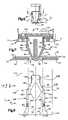
- FIG. 7is a sectional view taken generally along line 7 — 7 of FIG. 1 showing parts of the fastener in the first condition;
- FIG. 8is a bottom plan view of portions of the fastener of FIG. 1 , showing the parts of the fastener in the first condition;
- FIG. 9is a top plan view of the fastener of FIG. 1 , similar to FIG. 6 , showing the fastener in a second or locking condition;
- FIG. 10is a sectional view taken generally along line 10 — 10 of FIG. 9 , showing the parts of the fastener in the second condition;
- FIG. 11is a bottom plan view of portions of the fastener of FIG. 1 , showing the parts of the fastener in the second condition;
- FIG. 12is a top plan view of the fastener of FIG. 1 , similar to FIG. 6 , showing the fastener in a third or release condition;
- FIG. 13is a sectional view taken generally along line 13 — 13 of FIG. 12 showing the parts of the fastener in the third condition.
- FIG. 14is a bottom plan view of portions of the fastener of FIG. 1 , showing the parts of the fastener in the third condition.
- FIG. 1illustrates a two-part fastener 10 in accordance with the invention.
- the fastenerincludes a base 12 and a slide 14 .
- the fasteneris used for releasably securing together two or more members in an overlying relationship.
- the fasteneris used for releasably securing together a first member 20 ( FIG. 7 ) and a second member 22 .
- the first and second members 20 and 22may be, for example, portions of a vehicle door, such as a support panel and a trim panel, or may be two plates or other pieces.
- the first member 20( FIG. 7 ) has opposite inner (that is, away from the side of entry of the fastener, or to the bottom as viewed in FIG. 7 ) and outer major side surfaces 26 and 28 .
- the first member 20has a rectangular slot 30 extending between the inner and outer major side surfaces 26 and 28 .
- the second member 22has opposite inner and outer major side surfaces 32 and 34 .
- the outer major side surface 34 of the second member 22is in abutting engagement with the inner major side surface 26 of the first member 20 .
- the second member 22( FIG. 4 ) has a rectangular slot 36 extending between the inner and outer major side surfaces 32 and 34 .
- the slot 36 in the second member 22may be similar or identical in configuration to the slot 30 in the first member.
- the slot 36 in the second member 22overlies the slot 30 in the first member 20 and together they form an opening 40 in the two members 20 and 22 .
- the opening 40has a length extending between first and second edge surfaces 42 and 44 .
- the fastener 10extends into the opening 40 , in a manner described below, to clamp the first member 20 to the second member 22 .
- the base 12 ( FIGS. 1 and 2 ) of the fastener 10is preferably molded as one piece from a plastic material, but could alternatively be made from a different material or in a different manner.
- the base 12includes a planar, rectangular main body portion 50 centered on a linear axis 51 .
- the main body portion 50has an outer major side surface 52 ( FIG. 2 ) and an inner major side surface 54 .
- the main body portion 50also has two rectangular openings 56 and 58 spaced apart from each other.
- the main body portionhas parallel first and second side portions 61 and 62 , and parallel first and second end portions 63 and 64 .
- At the side portions 61 and 62are located inwardly facing tracks 65 and 66 , respectively, that project upwardly from the outer side surface of the main body portion.
- a detent finger 67is formed on the track 65
- a detent finger 68is formed on the track 66 .
- the arrangement of the tracks 65 and 66 , and of the detent fingers 67 and 68 ,is such that the base 12 appears the same when viewed from the first end portion 63 as when viewed from the second end portion 64 .
- the slide 14can be mounted on the base 12 , as described below, from either end portion 63 or 64 of the base.
- the base 12includes a retainer assembly 70 that depends from the main body portion 50 and that is movable into the opening 40 in the first and second members 20 and 22 , as described below.
- the retainer assembly 70includes two guide plates 72 and 74 that depend from the main body portion 50 on opposite sides of the two openings 56 and 58 .
- the retainer assembly 70also includes a central support post 76 that depends from the main body portion 50 between the two openings 56 and 58 .
- the support post 76has a rectangular cross-sectional configuration terminating in a lower end portion 78 that is curved for ease of insertion into the slot opening 40 .
- the retainer assembly 70further includes two engagement members 80 and 90 for engaging the inner side surface 26 of the first member 20 .
- the two engagement members 80 and 90are formed as resilient retaining legs that extend from the lower end portion 78 of the central support post 76 , in a direction toward the main body portion 50 of the base 12 .
- the two retaining legs 80 and 90are mirror images of each other, and are resiliently biased outward, away from each other.
- the first retaining leg 80is resiliently supported on the central support post 76 .
- the first retaining leg 80has a base portion 82 ( FIG. 7 ) that has a cam surface 84 that faces outward away from the support post 76 .
- the first retaining leg 80has an upper end portion 86 that extends upward from the base portion 82 .
- the upper end portion 86extends past the plane of the main body portion 50 and through the opening 56 in the main body portion.
- the upper end portion 86has a kidney-shaped cross-sectional configuration ( FIG. 4 ).
- the first retaining leg 80also has a blocking portion or blocking surface 88 ( FIG. 7 ) that extends between the upper end portion 86 and the cam surface 84 of the base portion 82 .
- the blocking surface 88faces outward, that is, away from the central support post 76 .
- the second retaining leg 90is a mirror image of the first retaining leg 80 .
- the second retaining leg 90is resiliently supported on the central support post 76 .
- the second retaining leg 90has a base portion 92 ( FIG. 7 ) that has a cam surface 94 that faces outward away from the support post 76 .
- the second retaining leg 90has an upper end portion 96 that extends upward from the base portion 92 .
- the upper end portion 96extends past the plane of the main body portion 50 and through the opening 58 in the main body portion.
- the upper end portion 96has a kidney-shaped cross-sectional configuration.
- the second retaining leg 90also has a blocking portion or blocking surface 98 that extends between the upper end portion 96 and the cam surface 94 of the base portion 92 .
- the blocking surface 98faces outward, that is, away from the central support post 76 .
- the slide 14( FIGS. 1 and 2 ) is preferably molded as one piece from the same plastic material as the base 12 , but could alternatively be made from a different material or in a different manner.
- the slide 14includes a planar, rectangular main body portion 100 having opposite inner and outer major side surfaces 102 and 104 .
- the main body portion 100 of the slide 14has parallel first and second side portions 106 and 108 , and parallel first and second end portions 110 and 112 .
- Three pairs of detent openings 114 , 116 and 118are formed in the outer side surface 104 of the slide 100 , near the side portions 106 and 108 .
- Two rib-shaped finger grips 120 and 122project from the outer side surface 104 at the end portions 110 and 112 , respectively, of the slide 14 .
- the finger grips 120 and 122are manually engageable to effect sliding movement of the slide 14 along the axis 51 relative to the base 12 .
- the finger grips 120 and 122do not extend the full width of the slide 14 .
- the side portions 106 and 108 of the slide 14project laterally outward from the finger grips 120 and 122 .
- the slide 14has a raised portion 130 .
- the raised portion 130projects from the outer side surface 104 of the main body portion 100 of the slide 14 .
- the raised portion 130includes a top wall 132 that is spaced upward from and extends parallel to the main body portion 100 .
- the raised portion 130also includes a support wall 134 that extends between the top wall 132 and the main body portion 100 of the slide 14 .
- the support wall 134supports the top wall 132 on the main body portion 100 .
- the main body portion 100is discontinuous at the location of the raised portion 130 .
- the slide 14is configured as if a section of the main body portion 100 were lifted upward to form the top wall 132 of the raised portion, then the support wall 134 was placed between them to support the top wall on the main body portion.
- the raised portion 130has a roughly V-shaped configuration that decreases in width as measured in a direction from the first end portion 106 to the second end portion 108 of the slid 14 .
- the raised portion 130extends to and between the finger grips 120 and 122 .
- the main body portion 100 of the slideis cut away to provide an access opening 136 that is the width of the raised portion 130 .
- the access opening 136enables access to a chamber 140 that is defined below the top wall 132 of the raised portion 130 and above the main body portion 100 , within the support wall 134 of the raised portion.
- the finger grip 122 at the second end portion 112 of the slidecloses the chamber 140 and forms an end wall of the chamber.
- a first direction of movement 142 of the slide 14is defined as movement of the slide along the axis 51 by which the first end portion 110 of the slide precedes the second end portion 112 of the slide-that is, with the open end of the chamber 140 leading and the closed end trailing.
- the inside surfaces of the support wall 134 of the raised portion 130 of the slide 14are engageable with the upper end portions 86 and 96 of the first and second retaining legs 80 and 90 .
- the support wallincludes first and second tracks 150 and 160 .
- the tracks 150 and 160extend from the access opening 136 to the finger grip 122 .
- the tracks 150 and 160are mirror images of each other about the axis 51 .
- the tracks 150 and 160converge as they extend away from the access opening 136 .
- the chamber 140located between the tracks 150 and 160 , tapers (decreases in width) from the first end portion 110 of the slide 14 to the second end portion 112 of the slide.
- the first track 150has four discrete, interconnected surfaces.
- the first surface 152extends inward toward the axis 51 as it extends in a direction from the open first end portion 110 of the slide 14 to the closed second end portion 112 .
- the second surface 154extends from the first surface 152 , in a direction parallel to the axis 51 .
- the third surface 156extends from the second surface inward toward the axis 51 as it extends in a direction from the open first end portion 110 of the slide 14 to the closed second end portion 112 .
- the fourth surface 158extends from the third surface 156 , in a direction parallel to the axis 51 .
- the fourth surface 158terminates in an end surface 159 of the support wall 134 .
- the second track 160is a mirror image of the first track 150 .
- the second side wallhas four discrete, interconnected surfaces.
- the first surface 162extends inward toward the axis 51 as it extends in a direction from the open first end portion 110 of the slide 14 to the closed second end portion 112 .
- the first surface 162is located opposite the first surface 152 of the first track 150 .
- the second surface 164extends from the first surface 162 , in a direction parallel to the axis 51 .
- the second surface 164is located opposite the second surface 154 of the first track 150 .
- the third surface 166extends inward toward the axis 51 as it extends in a direction from the open first end portion 112 of the slide 14 to the closed second end portion 112 .
- the third surface 166is located opposite the third surface 156 of the first track 150 .
- the fourth surface 168extends from the third surface 166 , in a direction parallel to the axis 51 .
- the fourth surface 168terminates in the end surface 159 of the support wall 134 .
- the fourth surface 168is located opposite the fourth surface 158 of the first track 150 .
- the pairs of opposite surfaces on the first and second tracks 150 and 160define portions of the chamber 140 .
- a first portion 172 of the chamber 140is defined between the first surfaces 152 and 162 .
- a second portion 174 of the chamber 140is defined between the second surfaces 154 and 164 .
- a third portion 176 of the chamber 140is defined between the third surfaces 156 and 166 .
- a fourth portion 178 of the chamber 140is defined between the fourth surfaces 158 and 168 .
- the slide 14includes a stop 180 on the inner major side surface 102 of the main body portion 110 .
- the stop 180is a diamond-shaped projection centered on the axis 51 and projecting into the chamber 140 , specifically, into the second and third portions 174 and 176 of the chamber.
- the stop 180has two side surfaces 182 facing toward the open first end portion 110 end of the slide 14 , and two side surfaces 184 facing toward the closed second end portion 12 of the slide.
- the slide 14has two points 186 at its widest portion, located inward of the second surfaces 154 and 156 of the tracks 150 and 160 , respectively.
- the fastener 10is assembled by sliding the slide 14 onto the base 12 .
- the first end portion 110 of the slide 14is moved axially into the space between the tracks 65 and 66 of the base 12 .
- the edge portions 106 and 108 of the slide 14fit under the tracks 66 and 65 , respectively.
- the first finger grip 120extends laterally between the tracks 65 and 66 .
- the main body portion 100 of the slide 14overlies the main body portion 50 of the base 12 .
- the slide 14is supported on the base 12 for linear sliding movement relative to the base along the axis 51 .
- the end portions 86 and 96 of the retaining legs 80 and 90 of the baseengage the first sections 152 and 162 of the tracks 150 and 160 , and are cammed inward toward the axis 51 .
- the slide 14is moved axially in the first direction 142 until the pair of detent fingers 67 and 68 on the base 12 engage in the pair of first detent openings 118 in the base. In this position, the retaining legs 80 and 90 are self-biased outwardly against the second sections 154 and 164 of the slide tracks 150 and 160 .
- the parts of the fastenerare in an assembled or as-molded condition shown in FIG. 7 and in solid lines in FIG. 8 .
- the first retaining leg 80is biased outwardly and engages the second section 154 of the first track 150 .
- the second retaining leg 90is biased outwardly and engages the second section 164 of the second track 160 .
- the parts of the fastener 10assume a first condition, or insertion condition.
- the parts of the fastener 10are in substantially the same position as in the assembled condition shown in FIG. 7 and in solid lines in FIG. 8 , with the exception that the retaining legs 80 and 90 move inwardly, away from the tracks 150 and 160 , into the position shown in dashed lines in FIG. 8 .
- the cam surfaces 84 and 94 on the retaining legs 80 and 90engage the edge surfaces 42 and 44 of the opening 40 , and cam the retaining legs inward from their as-molded condition, toward the axis 51 .
- the fastener 10moves into the opening 40 until the inner side surface 54 of the main body portion 50 of the base 12 engages the outer side surface 28 of the first member 20 , as shown in FIG. 7 , to limit movement of the fastener in a direction into the opening.
- the retainer assembly 70moves far enough into the opening 40 that the blocking surfaces 88 and 98 move past the edge surfaces 42 and 44 .
- the retaining legs 80 and 90spring back outward, away from the axis 51 .
- the retaining legs 80 and 90move outward until the end portions 86 and 96 of the retaining legs engage the edge surfaces 42 and 44 of the opening 40 .
- the edge surfaces 42 and 44 of the opening 40resist further lateral movement of the retaining legs 80 and 90 .
- the blocking surface 88 on the first retaining leg 80 and the blocking surface 98 on the second retaining leg 90engage the inner major side surface 32 of the second member 22 . This engagement blocks or resists removal of the base 12 from the opening 40 .
- the blocking portions 88 and 98 of the legs 80 and 90are thus in a blocking position to block removal of the legs through the opening 40 .
- the retaining legs 80 and 90can, however, be bent inward to enable removal of the fastener 10 from the opening 40 , if sufficient axial force is placed on the fastener. Therefore, the fastener 10 is not locked, and the members 20 and 22 are not securely clamped together.
- the slide 14is moved (slid) relative to the base 12 in the first direction 142 .
- the slideslides relative to the base 12 , in a direction along the axis 51 , but the base does not move in the opening 40 because of the engagement of the retaining legs 80 and 90 in the opening.
- the slide 14is moved axially in the first direction 142 until the pair of detent fingers 67 and 68 on the base 12 engage in the pair of second detent openings 116 in the slide 14 .
- the first and second tracks 150 and 160 of the slidemove relative to the retaining legs 80 and 90 of the base, in the first direction 142 as viewed in FIGS. 8 and 11 , from the position shown in solid lines in FIG. 8 toward the position shown in FIG. 11 .
- the corner surface 186 on the stop 180 of the slide 14engages the inside of the first retaining leg 80 .
- the stop 180blocks inward movement of the first retaining leg 80
- the edge surface 42 of the opening 40blocks outward movement of the end portion 86 of the first retaining leg.
- the first retaining leg 80is clamped between the stop 180 and the edge 42 of the opening 140 , and can not move either inward or outward relative to the axis 51 .
- the stop 180engages the inside of the second retaining leg 90 .
- the corner 186 of the stop 180blocks inward movement of the second retaining leg 90
- the edge surface 44 of the opening 40blocks outward movement of the end portion 96 of the second retaining leg 90 .
- the second retaining leg 90is clamped between the stop 180 and the edge 44 of the opening 40 , and can not move either inward or outward relative to the axis 51 .
- the blocking portions 88 and 98 of the retaining legs 80 and 90are in a blocking position ( FIG. 10 ).
- the legs 80 and 90are blocked from inward movement by the stop 180 , and are blocked from outward movement by the edges 42 and 44 of the opening 40 .
- the retaining legs 80 and 90are locked in the position shown in FIGS. 10 and 11 .
- the retaining legs 80 and 90can not be moved to a position to allow removal of the base 12 from the opening 40 .
- the legs 80 and 90are blocked from upward movement by the engagement of the blocking surfaces 88 and 98 of the legs against the edges of the opening 40 . Therefore, the retaining legs 80 and 90 block removal of the fastener 10 from the opening 40 , and the first and second members 20 and 22 are clamped together.
- the slide 14is moved farther along the base 12 in the first direction 142 .
- the first and second tracks 130 and 150 on the slidemove in a direction along the axis 51 relative to the retaining legs 80 and 90 of the base 12 , from the position shown in FIG. 11 to the position shown in FIG. 14 .
- the stop 180moves away from the first retaining leg 80 , and the first track 150 slides along the first retaining leg.
- the third section 156 and then the fourth section 158 of the first track 150engage the end portion 86 of the first retaining leg 80 .
- the first retaining leg 80is cammed inwardly by the third section 156 , away from the edges of the opening 40 , into engagement with the fourth section 158 .
- the slide 14moves to a position in which the first retaining leg 80 is located radially inward of the fourth section 158 of the first track.
- the blocking surface 88 on the retaining leg 80is moved inwardly of the edge 42 of the opening 40 .
- the slide 14stops when the pair of detent fingers 67 and 68 on the base 12 engage in the pair of third detent openings 114 in the slide 14 .
- the stop 180 on the slide 14moves away from the second retaining leg 90 , and the second track 160 slides along the second retaining leg.
- the third section 166 and then the fourth section 168 of the second track 160engage the end portion 96 of the second retaining leg 90 .
- the slide 14moves to a position in which the second retaining leg 90 is located radially inward of the fourth section 168 of the second track 160 .
- the second retaining leg 90is cammed inwardly by the third section 166 , away from the edges of the opening 40 , into engagement with the fourth section 168 .
- the blocking surface 98 on the retaining leg 90is moved inwardly of the edge 44 of the opening 40 .
- the retaining legs 80 and 90do not block removal of the fastener 10 from the opening 40 .
- the first and second members 20 and 22are no longer clamped together, and the fastener 10 can be removed from the opening 40 .
Landscapes
- Engineering & Computer Science (AREA)
- General Engineering & Computer Science (AREA)
- Mechanical Engineering (AREA)
- Slide Fasteners (AREA)
- Bearings For Parts Moving Linearly (AREA)
Abstract
Description
Claims (12)
Priority Applications (2)
| Application Number | Priority Date | Filing Date | Title |
|---|---|---|---|
| US10/603,032US6994504B2 (en) | 2003-06-24 | 2003-06-24 | Two part slide fastener |
| DE102004030583ADE102004030583A1 (en) | 2003-06-24 | 2004-06-24 | Two-part sliding or sliding bracket |
Applications Claiming Priority (1)
| Application Number | Priority Date | Filing Date | Title |
|---|---|---|---|
| US10/603,032US6994504B2 (en) | 2003-06-24 | 2003-06-24 | Two part slide fastener |
Publications (2)
| Publication Number | Publication Date |
|---|---|
| US20040265094A1 US20040265094A1 (en) | 2004-12-30 |
| US6994504B2true US6994504B2 (en) | 2006-02-07 |
Family
ID=33539666
Family Applications (1)
| Application Number | Title | Priority Date | Filing Date |
|---|---|---|---|
| US10/603,032Expired - Fee RelatedUS6994504B2 (en) | 2003-06-24 | 2003-06-24 | Two part slide fastener |
Country Status (2)
| Country | Link |
|---|---|
| US (1) | US6994504B2 (en) |
| DE (1) | DE102004030583A1 (en) |
Cited By (15)
| Publication number | Priority date | Publication date | Assignee | Title |
|---|---|---|---|---|
| US20080142670A1 (en)* | 2006-12-13 | 2008-06-19 | Cvelbar Randall S | Devices, systems, and methods for mounting components |
| US20080227331A1 (en)* | 2006-03-11 | 2008-09-18 | Hon Hai Precision Ind. Co., Ltd. | Electrical connector retaining mechanism having slide clip member |
| USD586756S1 (en) | 2008-01-29 | 2009-02-17 | Clark Equipment Company | Electrical connector fastener |
| US20100223765A1 (en)* | 2009-03-05 | 2010-09-09 | Ford Global Technologies, Llc | Anti-rotation fastener for an automotive component and panel |
| US20110240815A1 (en)* | 2010-04-05 | 2011-10-06 | Timothy Chak | Snap-on hook and cover for sunshade |
| US20120110796A1 (en)* | 2008-11-04 | 2012-05-10 | Jean Luc Klein | Fastening clip |
| US20120174345A1 (en)* | 2009-09-16 | 2012-07-12 | Illinois Tool Works Inc. | Multi-piece snap clip fastener |
| WO2013086173A1 (en)* | 2011-12-09 | 2013-06-13 | Kessler Crane, Inc. | Camera mount |
| US20130193294A1 (en)* | 2010-08-27 | 2013-08-01 | Lap Shun Manufacture Co., Ltd. | Tripod head panel device |
| US8827219B2 (en) | 2011-12-09 | 2014-09-09 | Kessler Crane, Inc. | Quick release plate |
| US9331629B2 (en) | 2012-07-02 | 2016-05-03 | A. Raymond Et Cie | Photovoltaic frame fastener |
| US20160363262A1 (en)* | 2015-06-10 | 2016-12-15 | Connor Moelmann | Mounting Device |
| US9669770B1 (en)* | 2016-04-15 | 2017-06-06 | GM Global Technology Operations LLC | Adjustable fastener-holder assembly |
| CN107571813A (en)* | 2016-07-05 | 2018-01-12 | 福特环球技术公司 | Connection component, wire harness clip assembly and trim components for vehicle |
| US20230042533A1 (en)* | 2021-08-06 | 2023-02-09 | A. Raymond Et Cie | Cable routing fastener |
Families Citing this family (13)
| Publication number | Priority date | Publication date | Assignee | Title |
|---|---|---|---|---|
| US7698787B2 (en)* | 2006-01-18 | 2010-04-20 | Illinois Tool Works Inc. | Fastener |
| JP2007263343A (en)* | 2006-03-30 | 2007-10-11 | Nippon Pop Rivets & Fasteners Ltd | Dismountable clip |
| DE102007042484B3 (en) | 2007-09-06 | 2009-01-08 | A. Raymond Et Cie | Device for fixing an attachment part to a support part comprises a manipulating structure having a guiding tongue placed on the free end of a front wall of a front wall arrangement and outwardly extending barrier wings |
| DE102007047535B3 (en)* | 2007-10-04 | 2008-12-11 | A. Raymond Et Cie | Device for attaching an attachment to a support part |
| BE1018296A3 (en)* | 2008-09-29 | 2010-08-03 | Ce & T Technics | |
| JP5371535B2 (en)* | 2009-04-24 | 2013-12-18 | 矢崎総業株式会社 | Clamp and electronic component built-in unit |
| GB0909984D0 (en)* | 2009-06-11 | 2009-07-22 | Rolls Royce Plc | Fastener |
| US8671528B2 (en)* | 2009-06-12 | 2014-03-18 | Piolax, Inc. | Assembling construction of clip to mountable member |
| DE102009024983B4 (en) | 2009-06-16 | 2013-09-05 | Trw Automotive Electronics & Components Gmbh | joint assembly |
| DE102011017053B4 (en)* | 2011-04-14 | 2014-01-16 | Vm Edelstahltechnik Gmbh | Clamping element for fastening solar modules and fastening device |
| US9631662B2 (en) | 2014-03-19 | 2017-04-25 | Ramco Specialties, Inc. | Spring clip apparatus |
| MX2017002671A (en)* | 2014-08-29 | 2017-11-28 | Avery Dennison Retail Information Services Llc | Fastner with reusable insert fastening element. |
| DE102017121449A1 (en) | 2017-09-15 | 2019-03-21 | Böllhoff Verbindungstechnik GmbH | Fastener for detachably connecting two components |
Citations (20)
| Publication number | Priority date | Publication date | Assignee | Title |
|---|---|---|---|---|
| US4276806A (en)* | 1978-07-13 | 1981-07-07 | Itw De France | Self-retained and reusable fastener |
| US4391559A (en)* | 1980-07-28 | 1983-07-05 | Nifco Inc. | Plastic fastener |
| US5134923A (en)* | 1989-04-15 | 1992-08-04 | Zeev Wexler | Linear to rotary movement valve actuator |
| US5163796A (en)* | 1992-05-29 | 1992-11-17 | Belser Jess L | Fastening bolt assembly providing both axial and radial holding forces |
| US5211519A (en)* | 1991-03-11 | 1993-05-18 | Nifco, Inc. | Plastic grommet |
| US5507545A (en)* | 1994-07-05 | 1996-04-16 | Trw Inc. | Visor clip assembly and releasable fastener |
| US5636937A (en)* | 1994-08-30 | 1997-06-10 | Harley-Davidson Motor Company | Universal connector anchor |
| US5732916A (en)* | 1996-05-22 | 1998-03-31 | Trw Inc. | Attachment plate for connection to vehicle panels |
| US5850676A (en)* | 1997-03-12 | 1998-12-22 | Nifco Inc. | Clip with engaging mechanism |
| JPH1125803A (en)* | 1997-06-30 | 1999-01-29 | Olympus Optical Co Ltd | Slide operation mechanism and slide lug |
| US5899910A (en)* | 1996-09-17 | 1999-05-04 | Etman; Sameer A. | Direct acting cam gripping mechanism |
| US6007285A (en) | 1995-06-19 | 1999-12-28 | Pinnacle Innovations | Cantilever fastener assembly |
| US6176660B1 (en)* | 1998-07-24 | 2001-01-23 | Trw Inc. | Releasable fastener with lateral stabilizing brace members and latch legs carrying fastener insertion guide |
| US6196756B1 (en)* | 1997-03-24 | 2001-03-06 | Illinois Tool Works Inc. | Releasable fastener assembly for preferred use in a vehicle |
| US6406242B1 (en)* | 2000-11-10 | 2002-06-18 | Trw Inc. | Apparatus for fastening together two plates |
| US6474921B1 (en)* | 2001-07-17 | 2002-11-05 | Trw Inc. | Two part twist fastener |
| US20020176762A1 (en)* | 2001-05-24 | 2002-11-28 | Moerke Benjamin H. | Removable and reusable fastener |
| US6652206B2 (en)* | 2002-02-20 | 2003-11-25 | Illinois Tool Works Inc. | Self-locking rivet fastener |
| US20040016088A1 (en)* | 2002-07-25 | 2004-01-29 | Angellotti Roger A. | Self aligning panel fastener |
| US20040020016A1 (en)* | 2002-06-12 | 2004-02-05 | Piolax, Inc. | Two-piece clip |
- 2003
- 2003-06-24USUS10/603,032patent/US6994504B2/ennot_activeExpired - Fee Related
- 2004
- 2004-06-24DEDE102004030583Apatent/DE102004030583A1/ennot_activeCeased
Patent Citations (20)
| Publication number | Priority date | Publication date | Assignee | Title |
|---|---|---|---|---|
| US4276806A (en)* | 1978-07-13 | 1981-07-07 | Itw De France | Self-retained and reusable fastener |
| US4391559A (en)* | 1980-07-28 | 1983-07-05 | Nifco Inc. | Plastic fastener |
| US5134923A (en)* | 1989-04-15 | 1992-08-04 | Zeev Wexler | Linear to rotary movement valve actuator |
| US5211519A (en)* | 1991-03-11 | 1993-05-18 | Nifco, Inc. | Plastic grommet |
| US5163796A (en)* | 1992-05-29 | 1992-11-17 | Belser Jess L | Fastening bolt assembly providing both axial and radial holding forces |
| US5507545A (en)* | 1994-07-05 | 1996-04-16 | Trw Inc. | Visor clip assembly and releasable fastener |
| US5636937A (en)* | 1994-08-30 | 1997-06-10 | Harley-Davidson Motor Company | Universal connector anchor |
| US6007285A (en) | 1995-06-19 | 1999-12-28 | Pinnacle Innovations | Cantilever fastener assembly |
| US5732916A (en)* | 1996-05-22 | 1998-03-31 | Trw Inc. | Attachment plate for connection to vehicle panels |
| US5899910A (en)* | 1996-09-17 | 1999-05-04 | Etman; Sameer A. | Direct acting cam gripping mechanism |
| US5850676A (en)* | 1997-03-12 | 1998-12-22 | Nifco Inc. | Clip with engaging mechanism |
| US6196756B1 (en)* | 1997-03-24 | 2001-03-06 | Illinois Tool Works Inc. | Releasable fastener assembly for preferred use in a vehicle |
| JPH1125803A (en)* | 1997-06-30 | 1999-01-29 | Olympus Optical Co Ltd | Slide operation mechanism and slide lug |
| US6176660B1 (en)* | 1998-07-24 | 2001-01-23 | Trw Inc. | Releasable fastener with lateral stabilizing brace members and latch legs carrying fastener insertion guide |
| US6406242B1 (en)* | 2000-11-10 | 2002-06-18 | Trw Inc. | Apparatus for fastening together two plates |
| US20020176762A1 (en)* | 2001-05-24 | 2002-11-28 | Moerke Benjamin H. | Removable and reusable fastener |
| US6474921B1 (en)* | 2001-07-17 | 2002-11-05 | Trw Inc. | Two part twist fastener |
| US6652206B2 (en)* | 2002-02-20 | 2003-11-25 | Illinois Tool Works Inc. | Self-locking rivet fastener |
| US20040020016A1 (en)* | 2002-06-12 | 2004-02-05 | Piolax, Inc. | Two-piece clip |
| US20040016088A1 (en)* | 2002-07-25 | 2004-01-29 | Angellotti Roger A. | Self aligning panel fastener |
Non-Patent Citations (4)
| Title |
|---|
| Nayler, "Dictionary of Mechanical Engineering", 1997, Society of Automotive Engineers, Inc., 4th edition, p. 58, cover and title page.* |
| TRW Fasteners-Arrowhead for a slot, Jun. 1996. |
| TRW United Carr-Fastener, 1983. |
| U.S. Appl. No. 09/907,346, filed Jul. 17, 2001 entitled Two part Twist Fastener. |
Cited By (25)
| Publication number | Priority date | Publication date | Assignee | Title |
|---|---|---|---|---|
| US20080227331A1 (en)* | 2006-03-11 | 2008-09-18 | Hon Hai Precision Ind. Co., Ltd. | Electrical connector retaining mechanism having slide clip member |
| US7534134B2 (en)* | 2006-03-11 | 2009-05-19 | Hon Hai Precision Ind. Co., Ltd. | Electrical connector retaining mechanism having slide clip member |
| US20080142670A1 (en)* | 2006-12-13 | 2008-06-19 | Cvelbar Randall S | Devices, systems, and methods for mounting components |
| USD586756S1 (en) | 2008-01-29 | 2009-02-17 | Clark Equipment Company | Electrical connector fastener |
| US8601649B2 (en)* | 2008-11-04 | 2013-12-10 | Trw Automotive Electronics & Components Gmbh | Fastening clip |
| US20120110796A1 (en)* | 2008-11-04 | 2012-05-10 | Jean Luc Klein | Fastening clip |
| US20100223765A1 (en)* | 2009-03-05 | 2010-09-09 | Ford Global Technologies, Llc | Anti-rotation fastener for an automotive component and panel |
| US8221042B2 (en) | 2009-03-05 | 2012-07-17 | Ford Global Technologies, Llc | Anti-rotation fastener for an automotive component and panel |
| US8763212B2 (en)* | 2009-09-16 | 2014-07-01 | Illinois Tool Works Inc. | Multi-piece snap clip fastener |
| US20120174345A1 (en)* | 2009-09-16 | 2012-07-12 | Illinois Tool Works Inc. | Multi-piece snap clip fastener |
| US8141832B2 (en)* | 2010-04-05 | 2012-03-27 | Honda Motor Co., Ltd. | Snap-on hook and cover for sunshade |
| US20110240815A1 (en)* | 2010-04-05 | 2011-10-06 | Timothy Chak | Snap-on hook and cover for sunshade |
| US20130193294A1 (en)* | 2010-08-27 | 2013-08-01 | Lap Shun Manufacture Co., Ltd. | Tripod head panel device |
| US8979058B2 (en)* | 2010-08-27 | 2015-03-17 | Lap Shun Manufacture Co., Ltd. | Tripod head panel device |
| WO2013086173A1 (en)* | 2011-12-09 | 2013-06-13 | Kessler Crane, Inc. | Camera mount |
| US8807496B2 (en) | 2011-12-09 | 2014-08-19 | Kessler Crane, Inc. | Camera mount |
| US8827219B2 (en) | 2011-12-09 | 2014-09-09 | Kessler Crane, Inc. | Quick release plate |
| US9331629B2 (en) | 2012-07-02 | 2016-05-03 | A. Raymond Et Cie | Photovoltaic frame fastener |
| US20160363262A1 (en)* | 2015-06-10 | 2016-12-15 | Connor Moelmann | Mounting Device |
| US9669770B1 (en)* | 2016-04-15 | 2017-06-06 | GM Global Technology Operations LLC | Adjustable fastener-holder assembly |
| CN107571813A (en)* | 2016-07-05 | 2018-01-12 | 福特环球技术公司 | Connection component, wire harness clip assembly and trim components for vehicle |
| US20180370456A1 (en)* | 2016-07-05 | 2018-12-27 | Ford Global Technologies, Llc | Connection assemblies in a vehicle |
| US10486619B2 (en)* | 2016-07-05 | 2019-11-26 | Ford Global Technologies Llc | Connection assemblies in a vehicle |
| US20230042533A1 (en)* | 2021-08-06 | 2023-02-09 | A. Raymond Et Cie | Cable routing fastener |
| US11692649B2 (en)* | 2021-08-06 | 2023-07-04 | A. Raymond Et Cie | Cable routing fastener |
Also Published As
| Publication number | Publication date |
|---|---|
| US20040265094A1 (en) | 2004-12-30 |
| DE102004030583A1 (en) | 2005-01-27 |
Similar Documents
| Publication | Publication Date | Title |
|---|---|---|
| US6994504B2 (en) | Two part slide fastener | |
| US6474921B1 (en) | Two part twist fastener | |
| CN110778798B (en) | Hinge structure | |
| US5368427A (en) | Quarter turn fastener | |
| US6677526B2 (en) | Protector for wire harness | |
| KR20200028302A (en) | Sealing pin and grommet fastener accommodating two directional offset | |
| US9217453B2 (en) | Mounting structure for parts | |
| US9956925B2 (en) | Attaching structure assembly for an attached component | |
| CN103026078B (en) | Clip | |
| US6557956B2 (en) | Cabinets with false fronts and associated false front connectors for engaging multiple sidewalls | |
| EP0413805A1 (en) | BATTERY HOUSING. | |
| US5419744A (en) | Joining device | |
| CN108223510B (en) | Clamp for fixing a first element to a second element | |
| US20110192629A1 (en) | Cable management system | |
| US5508124A (en) | Confined battery door | |
| US4605265A (en) | Drawer slide bumper | |
| CA2330940C (en) | Rectangular panel fastener | |
| US20200158154A1 (en) | Connector, system consisting of a connector and a latching pin of a second component, said latching pin having a head, and method for using such a system | |
| US5479682A (en) | Clamp for paper sheets | |
| GB2033043A (en) | Structural joint | |
| JPH0942237A (en) | Mounting structure for part | |
| JPH03281878A (en) | Closure unit and latch assembly and method for assembling thereof | |
| JPH0732205Y2 (en) | Belt molding clip | |
| US6171014B1 (en) | Clip with sliding lid for an automotive seat and similar applications | |
| JP2500517Y2 (en) | Rail mounting device for electrical equipment |
Legal Events
| Date | Code | Title | Description |
|---|---|---|---|
| AS | Assignment | Owner name:TRW AUTOMOTIVE U.S. LLC, MICHIGAN Free format text:ASSIGNMENT OF ASSIGNORS INTEREST;ASSIGNOR:GORDON, GARY G.;REEL/FRAME:014232/0868 Effective date:20030408 | |
| AS | Assignment | Owner name:JP MORGAN CHASE BANK, AS ADMINISTRATIVE AGENT, NEW Free format text:SECURITY AGREEMENT;ASSIGNOR:TRW AUTOMOTIVE U.S. LLC;REEL/FRAME:014590/0771 Effective date:20031015 | |
| FEPP | Fee payment procedure | Free format text:PAYOR NUMBER ASSIGNED (ORIGINAL EVENT CODE: ASPN); ENTITY STATUS OF PATENT OWNER: LARGE ENTITY | |
| AS | Assignment | Owner name:JPMORGAN CHASE BANK, N.A., NEW YORK Free format text:SECURITY INTEREST;ASSIGNORS:KELSEY-HAYES COMPANY;TRW AUTOMOTIVE U.S. LLC;TRW VEHICLE SAFETY SYSTEMS INC.;REEL/FRAME:015991/0001 Effective date:20050124 Owner name:JPMORGAN CHASE BANK, N.A.,NEW YORK Free format text:SECURITY INTEREST;ASSIGNORS:KELSEY-HAYES COMPANY;TRW AUTOMOTIVE U.S. LLC;TRW VEHICLE SAFETY SYSTEMS INC.;REEL/FRAME:015991/0001 Effective date:20050124 | |
| FPAY | Fee payment | Year of fee payment:4 | |
| AS | Assignment | Owner name:JPMORGAN CHASE BANK, N.A., AS COLLATERAL AGENT, NE Free format text:SECURITY AGREEMENT;ASSIGNORS:TRW VEHICLE SAFETY SYSTEMS INC.;TRW AUTOMOTIVE U.S. LLC;KELSEY-HAYES COMPANY;REEL/FRAME:029529/0534 Effective date:20120928 | |
| REMI | Maintenance fee reminder mailed | ||
| AS | Assignment | Owner name:KELSEY-HAYES COMPANY, MICHIGAN Free format text:RELEASE OF SECURITY INTEREST;ASSIGNOR:JPMORGAN CHASE BANK, N.A.;REEL/FRAME:031645/0697 Effective date:20131028 Owner name:TRW INTELLECTUAL PROPERTY CORP., MICHIGAN Free format text:RELEASE OF SECURITY INTEREST;ASSIGNOR:JPMORGAN CHASE BANK, N.A.;REEL/FRAME:031645/0697 Effective date:20131028 Owner name:TRW AUTOMOTIVE U.S. LLC, MICHIGAN Free format text:RELEASE OF SECURITY INTEREST;ASSIGNOR:JPMORGAN CHASE BANK, N.A.;REEL/FRAME:031645/0697 Effective date:20131028 Owner name:TRW VEHICLE SAFETY SYSTEMS INC., MICHIGAN Free format text:RELEASE OF SECURITY INTEREST;ASSIGNOR:JPMORGAN CHASE BANK, N.A.;REEL/FRAME:031645/0697 Effective date:20131028 | |
| LAPS | Lapse for failure to pay maintenance fees | ||
| STCH | Information on status: patent discontinuation | Free format text:PATENT EXPIRED DUE TO NONPAYMENT OF MAINTENANCE FEES UNDER 37 CFR 1.362 | |
| FP | Lapsed due to failure to pay maintenance fee | Effective date:20140207 |