US6994404B1 - Rotatable tool assembly - Google Patents
Rotatable tool assemblyDownload PDFInfo
- Publication number
- US6994404B1 US6994404B1US11/039,093US3909305AUS6994404B1US 6994404 B1US6994404 B1US 6994404B1US 3909305 AUS3909305 AUS 3909305AUS 6994404 B1US6994404 B1US 6994404B1
- Authority
- US
- United States
- Prior art keywords
- tool
- shank
- washer
- ring
- tool holder
- Prior art date
- Legal status (The legal status is an assumption and is not a legal conclusion. Google has not performed a legal analysis and makes no representation as to the accuracy of the status listed.)
- Expired - Fee Related
Links
- UONOETXJSWQNOL-UHFFFAOYSA-Ntungsten carbideChemical compound[W+]#[C-]UONOETXJSWQNOL-UHFFFAOYSA-N0.000claimsdescription9
- 230000000717retained effectEffects0.000claimsdescription3
- 239000000463materialSubstances0.000description5
- 229910000760Hardened steelInorganic materials0.000description2
- 239000010419fine particleSubstances0.000description2
- 238000012986modificationMethods0.000description2
- 230000004048modificationEffects0.000description2
- 229910000831SteelInorganic materials0.000description1
- 239000010426asphaltSubstances0.000description1
- 230000000712assemblyEffects0.000description1
- 238000000429assemblyMethods0.000description1
- 230000004323axial lengthEffects0.000description1
- 239000004567concreteSubstances0.000description1
- 230000002708enhancing effectEffects0.000description1
- 239000012634fragmentSubstances0.000description1
- 238000000034methodMethods0.000description1
- 230000002028prematureEffects0.000description1
- 229910001220stainless steelInorganic materials0.000description1
- 239000010935stainless steelSubstances0.000description1
- 239000010959steelSubstances0.000description1
Images


Classifications
- E—FIXED CONSTRUCTIONS
- E21—EARTH OR ROCK DRILLING; MINING
- E21C—MINING OR QUARRYING
- E21C35/00—Details of, or accessories for, machines for slitting or completely freeing the mineral from the seam, not provided for in groups E21C25/00 - E21C33/00, E21C37/00 or E21C39/00
- E21C35/18—Mining picks; Holders therefor
- E21C35/19—Means for fixing picks or holders
- E21C35/197—Means for fixing picks or holders using sleeves, rings or the like, as main fixing elements
Definitions
- the present inventionrelates to a mounting for rotatable tools used to cut hard surfaces and, in particular, to an improved mounting having a washer to protect portions of the mounting block that retains the tool and having an O-ring for centering the washer.
- a machine for cutting hard surfaceshas a rotatable member such as a wheel or a drum which turns about an axis and has a plurality of cutting tools mounted on the rotatable member. To advance the cut, the rotating member is applied against the hard surface such that each tool removes a small portion of hardened material.
- the cutting toolsare rotatably mounted about a longitudinal axis and have a cylindrically mounted portion rotatably fitted in a cylindrical aperture on a mounting block on the rotating member.
- the toolis provided with an annular flange having a planar rear surface which rests upon the planar forward surface of the mounting block surrounding the aperture such that the forward surface of the mounting block applies force to the rear surface of the flange.
- Each of the toolsalso has a tapered forward cutting end with a tungsten carbide insert at the forward end thereof for cutting into the hard surfaces.
- a tapered forward cutting endwith a tungsten carbide insert at the forward end thereof for cutting into the hard surfaces.
- the machinecuts hard material, such as concrete or asphalt, fragments of the broken material are forced across the tapered forward end of the tool and around the sides of the mounting block causing wear, or wash away, of the material which make up both the tool body and the mounting block. After a substantial portion of the forward end of the tool has been worn away, the tool must be replaced. Similarly, after a substantial portion of the mounting block has been washed away, the mounting block must also be replaced.
- a recent improvement in such machinesis a quick-change assembly wherein the cylindrical shank of the tool is received in a tubular retainer.
- the tubular retaineris then fitted into a mounting block on the machine. In this configuration, it is the tubular retainer and not the mounting block which suffers wash away when the machine is in use.
- the tubular retainercan be more easily replaced than the block into which it is mounted, thereby simplifying the repair of the machine.
- the tools used in such machinesare symmetric about their longitudinal axis and the rotation of the tool within the cylindrical mounting causes the tool body to wear evenly around its circumference. Even so, such tools become worn very rapidly and it is common to replace all of the tools on a machine after a single day of usage. A tool which does not rotate properly, however, will fail prematurely and the failure of several tools on a machine can cause the machine to be taken out of service before completion of a day's work. Proper rotation of the tools is, therefore, essential for operating the machine efficiently.
- the washeris made of a hardened steel and has a polished surface which acts as a bearing on which the rear surface of the flange is rotatable thereby enhancing tool rotation.
- the toolshave a frustoconical portion between the shank and the rearward surface of the flange and, therefor, the washer must have an inner diameter equal to the largest diameter of the frustoconical portion. If the washer is not properly centered on the tool while it is being inserted into the retainer or tool block, the washer will prevent the tool from being properly seated in its holder. An improperly seated tool will not rotate properly, and will contribute to the premature failure of the tool holder.
- the washers in such assembliesare to remain stationary with respect to the tool holder and not rotate with the tool.
- the washermay tend to rotate with the tool and thereby defeat its purpose.
- the tool holderis fitted with a tungsten carbide ring at the forward end therefore, such as disclosed in my co-pending application Ser. No. 09/505,088, there is a high likelihood that the washer will rotate with the tool because the tungsten carbide of the ring has a lower coefficient of friction than does the steel of the washer. It is desirable, therefore, to provide a method for facilitating the centering of the washer with respect to the tool and for retaining the washer stationary with respect to the tool holder and against rotation with the tool.
- the present inventionis embodied in an assembly for retaining a rotatable tool within a tool holder where the tool holder has a planar forward mounting surface and a cylindrical hole with a frustoconical counter sink, the axis of which is perpendicular to the mounting surface into which a cylindrical shank on the tool is received.
- the assemblyincludes a tool having a tapered forward cutting end, a radial flange aligned axially behind the forward cutting end, and a cylindrical shank axially aligned behind the radial flange. Between the shank and the radial flange is a frustoconical portion to facilitate the alignment of the tool within the tool holder. An expandable retainer sleeve is fitting around the circumference of the shank to retain the shank of the tool in the cylindrical hole of the tool holder.
- a washer having an inner diameter which is greater than the diameter of the transverse hole into which the shank and retainer sleeve are insertedis fitted around the shank of the tool and the retainer sleeve thereon.
- an O-ring having an inner diameter which is less than that of the inner diameter of the cylindrical hole in the tool holder and an outer diameter which is greater than the inner diameter of the washeris fitted over the shank and the retainer sleeve and behind the washer. The O-ring will therefore prevent the washer from falling off the end of the shank thereby retaining the parts in their desired relationship until the tool is placed in use.
- the worn toolis removed from the tool holder along with its associated retainer sleeve, washer and O-ring and all these parts are discarded. Thereafter, the shank of the replacement tool is inserted into the bore of the tool holder. As the shank and retainer sleeve are pressed into the bore of the tool holder, the O-ring will become seated in the frustoconical countersink at the forward end of the tool holder. As the shank and sleeve become fully inserted into the mounting hole, the inner diameter of the washer will become seated around the outer diameter of the O-ring, thereby centering the washer and allowing the tool to become properly seated. The rear surface of the washer will rest against the forward surface of the tool holder and the rear surface of the flange of the tool will rest against the forward surface of the washer.
- the inner circumference of the O-ringwill abut against the forward end of the sleeve and the outer diameter of the O-ring will abut against the inner diameter of the washer, thereby retaining the washer against rotation with the tool.
- FIG. 1is an exploded view of a tool mounting block and tool assembly in accordance with the present invention with portions of the interior of the block shown in broken lines;
- FIG. 2is an exploded cross sectional view of a quick change holder having a tungsten carbide wear ring at the forward end thereof and a tool assembly in accordance with the invention fitted therein;
- FIG. 3is a cross sectional view of the assembly as shown in FIG. 1 partially inserted into the mounting block;
- FIG. 4is another cross sectional view of the block and assembly shown in FIG. 1 with the tool fully inserted into the block;
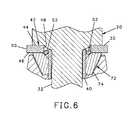
- FIG. 6is a fragmentary enlarged cross sectional view of the O-ring, washer, tool and tool holder shown in FIG. 2 with the tool completely assembled and showing in detail the wear ring, the washer and the O-ring.
- a tool mounting block 10has an attachment portion 12 attachable to the rotating member (not shown) of a machine.
- the block 10further has a planar forward surface 14 and extending through the body of the block is a transverse hole 16 having a longitudinal axis 18 perpendicular to the forward surface 14 .
- a frustoconical counter sink 19Near the forward surface 14 and surrounding the end of the hole 16 is a frustoconical counter sink 19 to facilitate the alignment of a tool as it is inserted into the block 10 .
- a tool 20having a tapered forward end 22 , at the most forward end of which is seat 24 into which is fitted a tungsten carbide insert 26 .
- a radial flange 28Rearward of the tapered forward end 22 is a radial flange 28 , having a planar rear surface 30 .
- cylindrical shank 32Positioned axially behind the planar rear surface 30 is cylindrical shank 32 having an enlarged hub 34 at the distal end thereof.
- a frustoconical portion 36Between the cylindrical shank 32 and the planar rear surface 30 of the flange is a frustoconical portion 36 , and between the frustoconical portion 36 and the shank 32 is a radial shoulder 38 .
- a retainer sleeve 40Fitted around the circumference of the cylindrical shank 32 is a retainer sleeve 40 having a “C” shaped cross section which is biased to expand to an outer diameter which is larger than the inner diameter of the transverse hole 16 .
- the retainer sleeve 40has an axial length which is a little less than the length of the shank 32 from the forward end of the hub 34 to the shoulder 38 such that the retainer 40 can be compressed around the shank 32 and the shank, with the retainer sleeve 40 thereon, inserted into the hole 16 of the mounting block 10 .
- a washer 42Fitted around the circumference of the shank 32 is a washer 42 having a planar forward and rearward surfaces 44 , 46 respectively, an inner annular surface 48 and an outer surface 50 .
- the diameter of the inner surface 48is equal to the largest diameter of the frustoconical portion 36 of the tool 20 and the outer surface 50 has a diameter that is a little larger than the largest outer diameter of the radial flange 28 .
- the washer 42is preferably made of hardened steel or stainless steel and the forward surface 44 thereof is polished to provide a smooth bearing on which the rear surface 30 of the flange rotates.
- the inventionfurther includes an O-ring 52 having an inner surface 54 the diameter of which is a little smaller than that of the inner diameter of the transverse hole 16 and an outer surface 56 with a diameter which is a little larger than the diameter of the inner surface 48 of the washer 42 .
- the parts form a replacement tool assembly 60includes a tool 20 , a retainer sleeve 40 , a washer 42 , and an O-ring 52 .
- the replacement partsare retained in assembled relationship with the retainer sleeve 40 fitted around the circumference of the shank 32 , and the washer 42 fitted over the shank 32 and the retainer sleeve 40 .
- the O-ring 52is fitted around the circumference of the retainer sleeve 40 and behind the washer 42 , thereby retaining the washer from falling off the end of the shank 32 .
- the tool assembly 60is also insertable in a quick change tool holder 62 .
- the tool holder 62is symmetric about a longitudinal axis 64 and has a tapered forward end 66 , a cylindrical mounting portion 68 and an axial hole 70 having an inner diameter sized to retain the shank 32 of a tool 20 with the sleeve 40 thereon.
- a quick-change holder in accordance with my co-pending application Ser. No. 90/505,088further has a tungsten carbide wear ring 72 fitted into a countersink 73 at the forward end of the tapered forward section 68 .
- the ring 72has a planar forward surface 74 , an inner surface with a diameter 76 approximately equal to the inner diameter of the transverse hole 70 , and a frustoconical countersink 78 to facilitate the alignment of the tool 20 as the shank 28 is inserted into the transverse hole 70 .
- the inner surface 54 of the O-ring 52will fit around the upper end of the retainer sleeve 40 and the outer surface 56 thereof will abut against the inner surface 48 of the washer 42 . Since the retainer sleeve 40 is biased to expand within the transverse hole 16 , 70 of the block 10 or holder 62 , the retainer sleeve 40 will not rotate with the tool 20 .
- the O-ring 52therefore, engages the stationary retainer sleeve 40 and the frustoconical countersink 78 and the cylindrical inner surface 48 of the washer 42 , thereby preventing the washer 42 from rotating with the tool 20 . Also, since the O-ring fits within the inner diameter of the washer 42 , the O-ring facilitates the alignment of the washer 42 with respect to the transverse mounting hole 16 , 70 .
- the outer surface 50 of the washer 42has a larger diameter than that of the radial flange 28 such that the outermost portions of the washer 42 provide additional protection of the forward surfaces of the mounting block 10 or tool holder 62 .
- the O-ring 52serves as a seal against fine particles of hard material loosened by the cutting tool 10 from working along the forward or rearward surfaces 44 , 46 of the washer 42 and into the transverse hole 16 , 70 of the tool holder. The presence of fine particles between the shank 32 and the inner surface of the transverse hole 16 , 70 and the frustoconical countersink 19 , 78 will cause these parts to become worn prematurely.
Landscapes
- Engineering & Computer Science (AREA)
- Mining & Mineral Resources (AREA)
- Mechanical Engineering (AREA)
- Life Sciences & Earth Sciences (AREA)
- General Life Sciences & Earth Sciences (AREA)
- Geochemistry & Mineralogy (AREA)
- Geology (AREA)
- Milling Processes (AREA)
- Gripping On Spindles (AREA)
- Jigs For Machine Tools (AREA)
Abstract
Description
This is a divisional application of my application filed Jan. 16, 2003 and assigned Ser. No. 10/345,562 now U.S. Pat. No. 6,863,352, which claimed priority from my previously filed provisional application filed Jan. 24, 2002 and assigned Ser. No. 60/352,112. The present invention relates to a mounting for rotatable tools used to cut hard surfaces and, in particular, to an improved mounting having a washer to protect portions of the mounting block that retains the tool and having an O-ring for centering the washer.
A machine for cutting hard surfaces has a rotatable member such as a wheel or a drum which turns about an axis and has a plurality of cutting tools mounted on the rotatable member. To advance the cut, the rotating member is applied against the hard surface such that each tool removes a small portion of hardened material.
To maximize their useful life, the cutting tools are rotatably mounted about a longitudinal axis and have a cylindrically mounted portion rotatably fitted in a cylindrical aperture on a mounting block on the rotating member. To transfer force from the mounting block to the tool, the tool is provided with an annular flange having a planar rear surface which rests upon the planar forward surface of the mounting block surrounding the aperture such that the forward surface of the mounting block applies force to the rear surface of the flange.
Each of the tools also has a tapered forward cutting end with a tungsten carbide insert at the forward end thereof for cutting into the hard surfaces. As the machine cuts hard material, such as concrete or asphalt, fragments of the broken material are forced across the tapered forward end of the tool and around the sides of the mounting block causing wear, or wash away, of the material which make up both the tool body and the mounting block. After a substantial portion of the forward end of the tool has been worn away, the tool must be replaced. Similarly, after a substantial portion of the mounting block has been washed away, the mounting block must also be replaced.
A recent improvement in such machines is a quick-change assembly wherein the cylindrical shank of the tool is received in a tubular retainer. The tubular retainer is then fitted into a mounting block on the machine. In this configuration, it is the tubular retainer and not the mounting block which suffers wash away when the machine is in use. The tubular retainer can be more easily replaced than the block into which it is mounted, thereby simplifying the repair of the machine.
Other improvements have also enhanced the life of the mounting block. For example, the radial flanges of the tools have been enlarged to protect the block from damage caused by wash away. In my co-pending application Ser. No. 09/505,088, 1 also disclosed a tungsten carbide insert provided at the forward end of the mounting block to reduce the damage to the block caused by the rotation of the tool within the cylindrical bore. As a result of such improvements, as many as one hundred tools may be worn out before a mounting block suffers such wear that it, too, must be replaced.
The tools used in such machines are symmetric about their longitudinal axis and the rotation of the tool within the cylindrical mounting causes the tool body to wear evenly around its circumference. Even so, such tools become worn very rapidly and it is common to replace all of the tools on a machine after a single day of usage. A tool which does not rotate properly, however, will fail prematurely and the failure of several tools on a machine can cause the machine to be taken out of service before completion of a day's work. Proper rotation of the tools is, therefore, essential for operating the machine efficiently.
It has become common to provide a washer around the circumference of the tool shank such that the washer is positioned between the forward surface of the tool body and the flange of the tool. The washer is made of a hardened steel and has a polished surface which acts as a bearing on which the rear surface of the flange is rotatable thereby enhancing tool rotation. When a tool becomes worn, both the tool and the washer are removed from the mounting block for the tool retainer and replaced with a new tool and a new washer.
Certain new problems are created, however, by the provision of a washer. For example, the tools have a frustoconical portion between the shank and the rearward surface of the flange and, therefor, the washer must have an inner diameter equal to the largest diameter of the frustoconical portion. If the washer is not properly centered on the tool while it is being inserted into the retainer or tool block, the washer will prevent the tool from being properly seated in its holder. An improperly seated tool will not rotate properly, and will contribute to the premature failure of the tool holder.
To operate properly, the washers in such assemblies are to remain stationary with respect to the tool holder and not rotate with the tool. Where the tool holder is provided with a polished forward surface, the washer may tend to rotate with the tool and thereby defeat its purpose. Where the tool holder is fitted with a tungsten carbide ring at the forward end therefore, such as disclosed in my co-pending application Ser. No. 09/505,088, there is a high likelihood that the washer will rotate with the tool because the tungsten carbide of the ring has a lower coefficient of friction than does the steel of the washer. It is desirable, therefore, to provide a method for facilitating the centering of the washer with respect to the tool and for retaining the washer stationary with respect to the tool holder and against rotation with the tool.
Briefly, the present invention is embodied in an assembly for retaining a rotatable tool within a tool holder where the tool holder has a planar forward mounting surface and a cylindrical hole with a frustoconical counter sink, the axis of which is perpendicular to the mounting surface into which a cylindrical shank on the tool is received.
The assembly includes a tool having a tapered forward cutting end, a radial flange aligned axially behind the forward cutting end, and a cylindrical shank axially aligned behind the radial flange. Between the shank and the radial flange is a frustoconical portion to facilitate the alignment of the tool within the tool holder. An expandable retainer sleeve is fitting around the circumference of the shank to retain the shank of the tool in the cylindrical hole of the tool holder.
In accordance with the invention, a washer having an inner diameter which is greater than the diameter of the transverse hole into which the shank and retainer sleeve are inserted is fitted around the shank of the tool and the retainer sleeve thereon. Thereafter, an O-ring having an inner diameter which is less than that of the inner diameter of the cylindrical hole in the tool holder and an outer diameter which is greater than the inner diameter of the washer is fitted over the shank and the retainer sleeve and behind the washer. The O-ring will therefore prevent the washer from falling off the end of the shank thereby retaining the parts in their desired relationship until the tool is placed in use.
To replace a tool assembly in accordance with the present invention, the worn tool is removed from the tool holder along with its associated retainer sleeve, washer and O-ring and all these parts are discarded. Thereafter, the shank of the replacement tool is inserted into the bore of the tool holder. As the shank and retainer sleeve are pressed into the bore of the tool holder, the O-ring will become seated in the frustoconical countersink at the forward end of the tool holder. As the shank and sleeve become fully inserted into the mounting hole, the inner diameter of the washer will become seated around the outer diameter of the O-ring, thereby centering the washer and allowing the tool to become properly seated. The rear surface of the washer will rest against the forward surface of the tool holder and the rear surface of the flange of the tool will rest against the forward surface of the washer.
After the tool is assembled into the tool holder, the inner circumference of the O-ring will abut against the forward end of the sleeve and the outer diameter of the O-ring will abut against the inner diameter of the washer, thereby retaining the washer against rotation with the tool.
A better and more complete understanding of the present invention will be had after a reading of the following detailed description taken in conjunction with the following drawings where:
Referring toFIG. 1 , atool mounting block 10 has anattachment portion 12 attachable to the rotating member (not shown) of a machine. Theblock 10 further has a planarforward surface 14 and extending through the body of the block is atransverse hole 16 having alongitudinal axis 18 perpendicular to theforward surface 14. Near theforward surface 14 and surrounding the end of thehole 16 is afrustoconical counter sink 19 to facilitate the alignment of a tool as it is inserted into theblock 10.
Referring toFIGS. 1 ,3,4 and5, received within thetransverse hole 16 is atool 20 having a taperedforward end 22, at the most forward end of which isseat 24 into which is fitted atungsten carbide insert 26. Rearward of the taperedforward end 22 is aradial flange 28, having a planarrear surface 30. Positioned axially behind the planarrear surface 30 iscylindrical shank 32 having anenlarged hub 34 at the distal end thereof. Between thecylindrical shank 32 and the planarrear surface 30 of the flange is afrustoconical portion 36, and between thefrustoconical portion 36 and theshank 32 is aradial shoulder 38.
Fitted around the circumference of thecylindrical shank 32 is aretainer sleeve 40 having a “C” shaped cross section which is biased to expand to an outer diameter which is larger than the inner diameter of thetransverse hole 16. Theretainer sleeve 40 has an axial length which is a little less than the length of theshank 32 from the forward end of thehub 34 to theshoulder 38 such that theretainer 40 can be compressed around theshank 32 and the shank, with theretainer sleeve 40 thereon, inserted into thehole 16 of the mountingblock 10. When theshank 32 is fully inserted into thehole 16, the radial pressure of thesleeve 40 will retain the tool therein and thecylindrical shank 32 will be rotatable within theretainer sleeve 40.
Fitted around the circumference of theshank 32 is awasher 42 having a planar forward and rearward surfaces44,46 respectively, an innerannular surface 48 and anouter surface 50. In the preferred embodiment, the diameter of theinner surface 48 is equal to the largest diameter of thefrustoconical portion 36 of thetool 20 and theouter surface 50 has a diameter that is a little larger than the largest outer diameter of theradial flange 28. Thewasher 42 is preferably made of hardened steel or stainless steel and theforward surface 44 thereof is polished to provide a smooth bearing on which therear surface 30 of the flange rotates.
The invention further includes an O-ring 52 having aninner surface 54 the diameter of which is a little smaller than that of the inner diameter of thetransverse hole 16 and anouter surface 56 with a diameter which is a little larger than the diameter of theinner surface 48 of thewasher 42.
As best shown inFIG. 3 , the parts form areplacement tool assembly 60 includes atool 20, aretainer sleeve 40, awasher 42, and an O-ring 52. The replacement parts are retained in assembled relationship with theretainer sleeve 40 fitted around the circumference of theshank 32, and thewasher 42 fitted over theshank 32 and theretainer sleeve 40. The O-ring 52 is fitted around the circumference of theretainer sleeve 40 and behind thewasher 42, thereby retaining the washer from falling off the end of theshank 32.
Referring toFIGS. 2 and 6 , thetool assembly 60 is also insertable in a quickchange tool holder 62. Thetool holder 62 is symmetric about alongitudinal axis 64 and has a taperedforward end 66, acylindrical mounting portion 68 and anaxial hole 70 having an inner diameter sized to retain theshank 32 of atool 20 with thesleeve 40 thereon. A quick-change holder in accordance with my co-pending application Ser. No. 90/505,088 further has a tungstencarbide wear ring 72 fitted into a countersink73 at the forward end of the taperedforward section 68. Thering 72 has a planarforward surface 74, an inner surface with a diameter76 approximately equal to the inner diameter of thetransverse hole 70, and a frustoconical countersink78 to facilitate the alignment of thetool 20 as theshank 28 is inserted into thetransverse hole 70.
Referring toFIGS. 4 ,5, and6, when thetool assembly 60 is inserted into a mountingblock 10 or atool holder 62, theinner surface 54 of the O-ring 52 will fit around the upper end of theretainer sleeve 40 and theouter surface 56 thereof will abut against theinner surface 48 of thewasher 42. Since theretainer sleeve 40 is biased to expand within thetransverse hole block 10 orholder 62, theretainer sleeve 40 will not rotate with thetool 20. The O-ring 52, therefore, engages thestationary retainer sleeve 40 and the frustoconical countersink78 and the cylindricalinner surface 48 of thewasher 42, thereby preventing thewasher 42 from rotating with thetool 20. Also, since the O-ring fits within the inner diameter of thewasher 42, the O-ring facilitates the alignment of thewasher 42 with respect to the transverse mountinghole
In accordance with another feature of the invention, theouter surface 50 of thewasher 42 has a larger diameter than that of theradial flange 28 such that the outermost portions of thewasher 42 provide additional protection of the forward surfaces of the mountingblock 10 ortool holder 62. Also, the O-ring 52 serves as a seal against fine particles of hard material loosened by the cuttingtool 10 from working along the forward or rearward surfaces44,46 of thewasher 42 and into thetransverse hole shank 32 and the inner surface of thetransverse hole frustoconical countersink 19,78 will cause these parts to become worn prematurely.
While the present invention has been described with respect to two embodiments, it will be appreciated that many modifications and variations may be made without departing from the true spirit and scope of the invention. It is, therefore, the intent of the appendent claims to cover all such variations and modifications which fall within the true spirit and scope of the invention.
Claims (8)
1. An assembly for retaining a tool in a tool holder comprising
a tool holder having a transverse cylindrical hole with a longitudinal axis and an inner diameter,
said tool holder having a planar forward surface perpendicular to said axis,
means for retaining said tool holder to a machine,
a tool having a tapered forward cutting end, a radial flange axially aligned behind said forward cutting end, a cylindrical shank axially aligned behind said radial flange, and said cylindrical shank having an outer diameter less than said inner diameter of said transverse hole,
a retainer sleeve around said cylindrical shank for retaining said shank in said cylindrical hole,
said retainer sleeve fitted around a portion of said shank,
a washer having an inner diameter, a forward surface and a rearward surface,
said washer fitted around said shank,
said shank and said retainer sleeve fitted into said transverse hole, and
an O-ring having a surface,
said O-ring fitted around said shank,
a first portion of said surface of said O-ring abutting against a stationary surface on one of said tool holder and said retainer sleeve and a second portion of said surface of said O-ring abutting a surface of said washer wherein said washer is retained against rotation with said tool.
2. The tool assembly in accordance withclaim 1 wherein said cylindrical hole has a frustoconical counter sink and said O-ring is seated in said frustoconical counter sink.
3. A tool assembly in accordance withclaim 1 wherein said tool holder has a tungsten carbide wear ring.
4. The tool assembly ofclaim 1 wherein said inner surface of said O-ring has a diameter less than said inner diameter of said transverse mounting hole.
5. In an assembly for retaining a tool in a tool holder having
a tool holder having a transverse cylindrical hole with a longitudinal axis and an inner diameter,
said holder having a planar forward surface perpendicular to said axis,
means for retaining said tool holder to a machine,
a tool having a tapered forward cutting end, a radial flange axially aligned behind said forward cutting end, a cylindrical shank axially aligned behind said radial flange, and said cylindrical shank having an outer diameter less than said inner diameter of said transverse hole,
a retainer sleeve around said cylindrical shank for retaining said shank in said cylindrical hole,
said retainer sleeve fitted around a portion of said shank,
a washer having an inner diameter, a forward surface and a rearward surface,
said washer fitted around said shank and around said retainer sleeve, and
said shank and said retainer sleeve fitted into said transverse hole, the improvement comprising
an O-ring having a surface,
said O-ring fitted around said shank,
a first portion of said surface of said O-ring abutting against a stationary surface on one of said tool holder and said retainer sleeve and a second portion of said surface of said O-ring abutting a surface of said washer wherein said washer is retained against rotation with said tool.
6. The improvement ofclaim 5 wherein said cylindrical hole has a frustoconical counter sink and said O-ring is seated in said frustoconical counter sink.
7. The improvement ofclaim 5 wherein said tool holder has a tungsten carbide wear ring.
8. The improvement ofclaim 5 wherein said inner surface of said O-ring has a diameter less than said inner diameter of said transverse mounting hole.
Priority Applications (1)
| Application Number | Priority Date | Filing Date | Title |
|---|---|---|---|
| US11/039,093US6994404B1 (en) | 2002-01-24 | 2005-01-20 | Rotatable tool assembly |
Applications Claiming Priority (3)
| Application Number | Priority Date | Filing Date | Title |
|---|---|---|---|
| US35211202P | 2002-01-24 | 2002-01-24 | |
| US10/345,562US6863352B2 (en) | 2002-01-24 | 2003-01-16 | Rotatable tool assembly |
| US11/039,093US6994404B1 (en) | 2002-01-24 | 2005-01-20 | Rotatable tool assembly |
Related Parent Applications (1)
| Application Number | Title | Priority Date | Filing Date |
|---|---|---|---|
| US10/345,562DivisionUS6863352B2 (en) | 2002-01-24 | 2003-01-16 | Rotatable tool assembly |
Publications (1)
| Publication Number | Publication Date |
|---|---|
| US6994404B1true US6994404B1 (en) | 2006-02-07 |
Family
ID=26994449
Family Applications (3)
| Application Number | Title | Priority Date | Filing Date |
|---|---|---|---|
| US10/345,562Expired - Fee RelatedUS6863352B2 (en) | 2002-01-24 | 2003-01-16 | Rotatable tool assembly |
| US10/828,822Expired - Fee RelatedUS6966611B1 (en) | 2002-01-24 | 2004-04-21 | Rotatable tool assembly |
| US11/039,093Expired - Fee RelatedUS6994404B1 (en) | 2002-01-24 | 2005-01-20 | Rotatable tool assembly |
Family Applications Before (2)
| Application Number | Title | Priority Date | Filing Date |
|---|---|---|---|
| US10/345,562Expired - Fee RelatedUS6863352B2 (en) | 2002-01-24 | 2003-01-16 | Rotatable tool assembly |
| US10/828,822Expired - Fee RelatedUS6966611B1 (en) | 2002-01-24 | 2004-04-21 | Rotatable tool assembly |
Country Status (1)
| Country | Link |
|---|---|
| US (3) | US6863352B2 (en) |
Cited By (110)
| Publication number | Priority date | Publication date | Assignee | Title |
|---|---|---|---|---|
| US20070290546A1 (en)* | 2006-06-16 | 2007-12-20 | Hall David R | A Wear Resistant Tool |
| US7320505B1 (en) | 2006-08-11 | 2008-01-22 | Hall David R | Attack tool |
| US20080036271A1 (en)* | 2006-08-11 | 2008-02-14 | Hall David R | Method for Providing a Degradation Drum |
| US20080035387A1 (en)* | 2006-08-11 | 2008-02-14 | Hall David R | Downhole Drill Bit |
| US20080035386A1 (en)* | 2006-08-11 | 2008-02-14 | Hall David R | Pick Assembly |
| US20080036276A1 (en)* | 2006-08-11 | 2008-02-14 | Hall David R | Lubricated Pick |
| US20080035380A1 (en)* | 2006-08-11 | 2008-02-14 | Hall David R | Pointed Diamond Working Ends on a Shear Bit |
| US20080035383A1 (en)* | 2006-08-11 | 2008-02-14 | Hall David R | Non-rotating Pick with a Pressed in Carbide Segment |
| US20080036275A1 (en)* | 2006-08-11 | 2008-02-14 | Hall David R | Retainer Sleeve in a Degradation Assembly |
| US7338135B1 (en) | 2006-08-11 | 2008-03-04 | Hall David R | Holder for a degradation assembly |
| US7347292B1 (en) | 2006-10-26 | 2008-03-25 | Hall David R | Braze material for an attack tool |
| USD566137S1 (en) | 2006-08-11 | 2008-04-08 | Hall David R | Pick bolster |
| US20080088172A1 (en)* | 2006-08-11 | 2008-04-17 | Hall David R | Holder Assembly |
| US20080099250A1 (en)* | 2006-10-26 | 2008-05-01 | Hall David R | Superhard Insert with an Interface |
| US7384105B2 (en) | 2006-08-11 | 2008-06-10 | Hall David R | Attack tool |
| US7387345B2 (en) | 2006-08-11 | 2008-06-17 | Hall David R | Lubricating drum |
| US7396086B1 (en) | 2007-03-15 | 2008-07-08 | Hall David R | Press-fit pick |
| US7413256B2 (en) | 2006-08-11 | 2008-08-19 | Hall David R | Washer for a degradation assembly |
| US7419224B2 (en) | 2006-08-11 | 2008-09-02 | Hall David R | Sleeve in a degradation assembly |
| US20080258536A1 (en)* | 2006-08-11 | 2008-10-23 | Hall David R | High-impact Resistant Tool |
| US7445294B2 (en) | 2006-08-11 | 2008-11-04 | Hall David R | Attack tool |
| US20080284234A1 (en)* | 2007-05-14 | 2008-11-20 | Hall David R | Pick with a Reentrant |
| USD581952S1 (en)* | 2006-08-11 | 2008-12-02 | Hall David R | Pick |
| US7464993B2 (en) | 2006-08-11 | 2008-12-16 | Hall David R | Attack tool |
| US20080309149A1 (en)* | 2006-08-11 | 2008-12-18 | Hall David R | Braze Thickness Control |
| US20090051211A1 (en)* | 2006-10-26 | 2009-02-26 | Hall David R | Thick Pointed Superhard Material |
| US20090066149A1 (en)* | 2007-09-07 | 2009-03-12 | Hall David R | Pick with Carbide Cap |
| US20090133938A1 (en)* | 2006-08-11 | 2009-05-28 | Hall David R | Thermally Stable Pointed Diamond with Increased Impact Resistance |
| US20090142151A1 (en)* | 2007-11-30 | 2009-06-04 | The Sollami Company | Quick-change tool holder |
| US20090160238A1 (en)* | 2007-12-21 | 2009-06-25 | Hall David R | Retention for Holder Shank |
| US7568770B2 (en) | 2006-06-16 | 2009-08-04 | Hall David R | Superhard composite material bonded to a steel body |
| US20090200857A1 (en)* | 2006-08-11 | 2009-08-13 | Hall David R | Manually Rotatable Tool |
| US20090200855A1 (en)* | 2006-08-11 | 2009-08-13 | Hall David R | Manually Rotatable Tool |
| USD601592S1 (en)* | 2009-03-27 | 2009-10-06 | Richard Wayne Watson | Pocket protecting retainable cutter bit |
| US7600544B1 (en) | 2004-11-15 | 2009-10-13 | The Sollami Company | Retainer for a rotatable tool |
| US20090267403A1 (en)* | 2006-08-11 | 2009-10-29 | Hall David R | Resilient Pick Shank |
| US20090294182A1 (en)* | 2006-08-11 | 2009-12-03 | Hall David R | Degradation Assembly |
| US7628233B1 (en) | 2008-07-23 | 2009-12-08 | Hall David R | Carbide bolster |
| US7635168B2 (en) | 2006-08-11 | 2009-12-22 | Hall David R | Degradation assembly shield |
| US7637574B2 (en) | 2006-08-11 | 2009-12-29 | Hall David R | Pick assembly |
| US7648210B2 (en) | 2006-08-11 | 2010-01-19 | Hall David R | Pick with an interlocked bolster |
| US7669938B2 (en) | 2006-08-11 | 2010-03-02 | Hall David R | Carbide stem press fit into a steel body of a pick |
| US20100054875A1 (en)* | 2006-08-11 | 2010-03-04 | Hall David R | Test Fixture that Positions a Cutting Element at a Positive Rake Angle |
| US20100065332A1 (en)* | 2006-08-11 | 2010-03-18 | Hall David R | Method for Drilling with a Fixed Bladed Bit |
| US7712693B2 (en) | 2006-08-11 | 2010-05-11 | Hall David R | Degradation insert with overhang |
| US7722127B2 (en) | 2006-08-11 | 2010-05-25 | Schlumberger Technology Corporation | Pick shank in axial tension |
| US7740414B2 (en) | 2005-03-01 | 2010-06-22 | Hall David R | Milling apparatus for a paved surface |
| US20100263939A1 (en)* | 2006-10-26 | 2010-10-21 | Hall David R | High Impact Resistant Tool with an Apex Width between a First and Second Transitions |
| US20100264721A1 (en)* | 2009-04-16 | 2010-10-21 | Hall David R | Seal with Rigid Element for Degradation Assembly |
| US20100275425A1 (en)* | 2009-04-29 | 2010-11-04 | Hall David R | Drill Bit Cutter Pocket Restitution |
| US7832808B2 (en) | 2007-10-30 | 2010-11-16 | Hall David R | Tool holder sleeve |
| US20110080036A1 (en)* | 2007-05-15 | 2011-04-07 | Schlumberger Technology Corporation | Spring Loaded Pick |
| US7946657B2 (en) | 2006-08-11 | 2011-05-24 | Schlumberger Technology Corporation | Retention for an insert |
| US7950746B2 (en) | 2006-06-16 | 2011-05-31 | Schlumberger Technology Corporation | Attack tool for degrading materials |
| US7992945B2 (en) | 2006-08-11 | 2011-08-09 | Schlumberger Technology Corporation | Hollow pick shank |
| US7997661B2 (en) | 2006-08-11 | 2011-08-16 | Schlumberger Technology Corporation | Tapered bore in a pick |
| US8007051B2 (en) | 2006-08-11 | 2011-08-30 | Schlumberger Technology Corporation | Shank assembly |
| US8007050B2 (en) | 2006-08-11 | 2011-08-30 | Schlumberger Technology Corporation | Degradation assembly |
| US8061457B2 (en) | 2009-02-17 | 2011-11-22 | Schlumberger Technology Corporation | Chamfered pointed enhanced diamond insert |
| US8250786B2 (en) | 2010-06-30 | 2012-08-28 | Hall David R | Measuring mechanism in a bore hole of a pointed cutting element |
| US8414085B2 (en) | 2006-08-11 | 2013-04-09 | Schlumberger Technology Corporation | Shank assembly with a tensioned element |
| US8449040B2 (en) | 2006-08-11 | 2013-05-28 | David R. Hall | Shank for an attack tool |
| US8485609B2 (en) | 2006-08-11 | 2013-07-16 | Schlumberger Technology Corporation | Impact tool |
| US8540037B2 (en) | 2008-04-30 | 2013-09-24 | Schlumberger Technology Corporation | Layered polycrystalline diamond |
| US8567532B2 (en) | 2006-08-11 | 2013-10-29 | Schlumberger Technology Corporation | Cutting element attached to downhole fixed bladed bit at a positive rake angle |
| US8646848B2 (en) | 2007-12-21 | 2014-02-11 | David R. Hall | Resilient connection between a pick shank and block |
| US8668275B2 (en) | 2011-07-06 | 2014-03-11 | David R. Hall | Pick assembly with a contiguous spinal region |
| US8728382B2 (en) | 2011-03-29 | 2014-05-20 | David R. Hall | Forming a polycrystalline ceramic in multiple sintering phases |
| US9051795B2 (en) | 2006-08-11 | 2015-06-09 | Schlumberger Technology Corporation | Downhole drill bit |
| US9051794B2 (en) | 2007-04-12 | 2015-06-09 | Schlumberger Technology Corporation | High impact shearing element |
| US9068410B2 (en) | 2006-10-26 | 2015-06-30 | Schlumberger Technology Corporation | Dense diamond body |
| US9879531B2 (en) | 2014-02-26 | 2018-01-30 | The Sollami Company | Bit holder shank and differential interference between the shank distal portion and the bit holder block bore |
| US9909416B1 (en) | 2013-09-18 | 2018-03-06 | The Sollami Company | Diamond tipped unitary holder/bit |
| US9915102B2 (en) | 2006-08-11 | 2018-03-13 | Schlumberger Technology Corporation | Pointed working ends on a bit |
| US9976418B2 (en) | 2014-04-02 | 2018-05-22 | The Sollami Company | Bit/holder with enlarged ballistic tip insert |
| US9988903B2 (en) | 2012-10-19 | 2018-06-05 | The Sollami Company | Combination polycrystalline diamond bit and bit holder |
| US10072501B2 (en) | 2010-08-27 | 2018-09-11 | The Sollami Company | Bit holder |
| US10105870B1 (en) | 2012-10-19 | 2018-10-23 | The Sollami Company | Combination polycrystalline diamond bit and bit holder |
| US10107098B2 (en) | 2016-03-15 | 2018-10-23 | The Sollami Company | Bore wear compensating bit holder and bit holder block |
| US10107097B1 (en) | 2012-10-19 | 2018-10-23 | The Sollami Company | Combination polycrystalline diamond bit and bit holder |
| US10180065B1 (en) | 2015-10-05 | 2019-01-15 | The Sollami Company | Material removing tool for road milling mining and trenching operations |
| US10260342B1 (en) | 2012-10-19 | 2019-04-16 | The Sollami Company | Combination polycrystalline diamond bit and bit holder |
| US10323515B1 (en) | 2012-10-19 | 2019-06-18 | The Sollami Company | Tool with steel sleeve member |
| US10337324B2 (en) | 2015-01-07 | 2019-07-02 | The Sollami Company | Various bit holders and unitary bit/holders for use with shortened depth bit holder blocks |
| US10385689B1 (en) | 2010-08-27 | 2019-08-20 | The Sollami Company | Bit holder |
| US10415386B1 (en) | 2013-09-18 | 2019-09-17 | The Sollami Company | Insertion-removal tool for holder/bit |
| US10502056B2 (en) | 2015-09-30 | 2019-12-10 | The Sollami Company | Reverse taper shanks and complementary base block bores for bit assemblies |
| US10577931B2 (en) | 2016-03-05 | 2020-03-03 | The Sollami Company | Bit holder (pick) with shortened shank and angular differential between the shank and base block bore |
| US10598013B2 (en) | 2010-08-27 | 2020-03-24 | The Sollami Company | Bit holder with shortened nose portion |
| US10612375B2 (en) | 2016-04-01 | 2020-04-07 | The Sollami Company | Bit retainer |
| US10612376B1 (en) | 2016-03-15 | 2020-04-07 | The Sollami Company | Bore wear compensating retainer and washer |
| US10633971B2 (en) | 2016-03-07 | 2020-04-28 | The Sollami Company | Bit holder with enlarged tire portion and narrowed bit holder block |
| US10767478B2 (en) | 2013-09-18 | 2020-09-08 | The Sollami Company | Diamond tipped unitary holder/bit |
| US10794181B2 (en) | 2014-04-02 | 2020-10-06 | The Sollami Company | Bit/holder with enlarged ballistic tip insert |
| US10876401B1 (en) | 2016-07-26 | 2020-12-29 | The Sollami Company | Rotational style tool bit assembly |
| US10876402B2 (en) | 2014-04-02 | 2020-12-29 | The Sollami Company | Bit tip insert |
| US10947844B1 (en) | 2013-09-18 | 2021-03-16 | The Sollami Company | Diamond Tipped Unitary Holder/Bit |
| US10968739B1 (en) | 2013-09-18 | 2021-04-06 | The Sollami Company | Diamond tipped unitary holder/bit |
| US10968738B1 (en) | 2017-03-24 | 2021-04-06 | The Sollami Company | Remanufactured conical bit |
| US10995613B1 (en) | 2013-09-18 | 2021-05-04 | The Sollami Company | Diamond tipped unitary holder/bit |
| US11103939B2 (en) | 2018-07-18 | 2021-08-31 | The Sollami Company | Rotatable bit cartridge |
| US11168563B1 (en) | 2013-10-16 | 2021-11-09 | The Sollami Company | Bit holder with differential interference |
| US11187080B2 (en) | 2018-04-24 | 2021-11-30 | The Sollami Company | Conical bit with diamond insert |
| WO2021243892A1 (en)* | 2020-05-31 | 2021-12-09 | 苏州五元素机械制造有限公司 | Chisel |
| US11261731B1 (en) | 2014-04-23 | 2022-03-01 | The Sollami Company | Bit holder and unitary bit/holder for use in shortened depth base blocks |
| US11279012B1 (en) | 2017-09-15 | 2022-03-22 | The Sollami Company | Retainer insertion and extraction tool |
| US11339656B1 (en) | 2014-02-26 | 2022-05-24 | The Sollami Company | Rear of base block |
| US11339654B2 (en) | 2014-04-02 | 2022-05-24 | The Sollami Company | Insert with heat transfer bore |
| US11891895B1 (en) | 2014-04-23 | 2024-02-06 | The Sollami Company | Bit holder with annular rings |
| US12345158B1 (en) | 2019-06-20 | 2025-07-01 | The Sollami Company | Bit tip insert |
Families Citing this family (30)
| Publication number | Priority date | Publication date | Assignee | Title |
|---|---|---|---|---|
| US7139218B2 (en)* | 2003-08-13 | 2006-11-21 | Intelliserv, Inc. | Distributed downhole drilling network |
| TWD108996S1 (en)* | 2004-06-17 | 2006-02-01 | 貝泰克伯格及哈特梅塔泰克尼克卡爾海涅茲西蒙有限兩合公司 | Chisel |
| DE102004044897C5 (en)* | 2004-09-14 | 2013-01-03 | Betek Gmbh & Co. Kg | Attachment of a round shank chisel |
| US7135933B2 (en) | 2004-09-29 | 2006-11-14 | Intelliserv, Inc. | System for adjusting frequency of electrical output pulses derived from an oscillator |
| USD585259S1 (en)* | 2006-03-10 | 2009-01-27 | Wirtgen Bmbh | Chisel holder |
| USD574689S1 (en)* | 2006-03-10 | 2008-08-12 | Wirtgen Gmbh | Chisel holder |
| USD575610S1 (en)* | 2006-03-10 | 2008-08-26 | Wirtgen Gmbh | Chisel holder |
| US8403595B2 (en)* | 2006-12-01 | 2013-03-26 | David R. Hall | Plurality of liquid jet nozzles and a blower mechanism that are directed into a milling chamber |
| US8485756B2 (en)* | 2006-12-01 | 2013-07-16 | David R. Hall | Heated liquid nozzles incorporated into a moldboard |
| US7976239B2 (en)* | 2006-12-01 | 2011-07-12 | Hall David R | End of a moldboard positioned proximate a milling drum |
| DE202007018885U1 (en)* | 2007-10-29 | 2009-09-17 | Betek Bergbau- Und Hartmetalltechnik Karl-Heinz Simon Gmbh & Co. Kg | shank bits |
| US8020941B2 (en)* | 2008-12-11 | 2011-09-20 | Keystone Engineering & Manufacturing Corporation | Cutter bit insert removal system and method |
| US8528990B2 (en) | 2009-01-22 | 2013-09-10 | Keystone Engineering & Manufacturing Corporation | Cutter with diamond bit tip |
| US20100181820A1 (en) | 2009-01-22 | 2010-07-22 | Latham Winchester E | Wear insert and retainer |
| PL398127A1 (en)* | 2009-08-04 | 2012-07-30 | Sandvik Intellectual Property Ab | Non-rotating pad for a working insert of a tool and method for protecting the block and/or the sleeve surface using this pad |
| DE102009049780B4 (en)* | 2009-10-19 | 2016-02-18 | Betek Gmbh & Co. Kg | Chisel, in particular round shank chisel |
| US20120128415A1 (en)* | 2009-11-13 | 2012-05-24 | Mitsubishi Electric Corporation | Joint structure |
| USD627808S1 (en)* | 2009-12-23 | 2010-11-23 | Betek Bergbau- Und Hartmetalltechnik Karl-Heinz Simon Gmbh & Co. Kg | Chisel bit |
| US8262168B2 (en) | 2010-09-22 | 2012-09-11 | Hall David R | Multiple milling drums secured to the underside of a single milling machine |
| US20120019044A1 (en)* | 2010-07-26 | 2012-01-26 | Sandvik Intellectual Property Ab | Holder Block for Both Radial and Conical Tool Picks |
| EP2457678B1 (en)* | 2010-11-29 | 2016-03-30 | Techspace Aero S.A. | Bi-material one-piece cutting tool |
| DE102011054384A1 (en)* | 2011-10-11 | 2013-04-11 | Betek Gmbh & Co. Kg | toolholders |
| DE102011054393A1 (en)* | 2011-10-11 | 2013-04-11 | Betek Gmbh & Co. Kg | shank bits |
| US9028008B1 (en)* | 2014-01-16 | 2015-05-12 | Kennametal Inc. | Cutting tool assembly including retainer sleeve with compression band |
| WO2016061105A1 (en)* | 2014-10-17 | 2016-04-21 | Vermeer Manufacturing Company | Protective wear sleeve for cutting element |
| WO2019180554A1 (en)* | 2018-03-22 | 2019-09-26 | Beard Gavin James | A pick sleeve |
| US10843221B2 (en)* | 2018-11-06 | 2020-11-24 | The Boeing Company | System and method for a coating device |
| US11092008B2 (en)* | 2019-12-03 | 2021-08-17 | Ironhawk Industrial Distribution LLC | Grader bit |
| US12196360B2 (en) | 2021-11-05 | 2025-01-14 | Aob Products Company | Foot assembly with reversible spike |
| USD1065994S1 (en)* | 2022-07-29 | 2025-03-11 | Kennametal Inc. | Tool retainer |
Citations (4)
| Publication number | Priority date | Publication date | Assignee | Title |
|---|---|---|---|---|
| US4561698A (en) | 1984-06-21 | 1985-12-31 | Beebe Donald E | Wear protector for tooth brackets on roadway surface cutting machines |
| US4818027A (en) | 1987-01-23 | 1989-04-04 | Betek Bergbau-Und Hartmetalltechnik Karl-Heinz Simon Gmbh & Co. Kg | Round shaft bit |
| US5098167A (en) | 1990-10-01 | 1992-03-24 | Latham Winchester E | Tool block with non-rotating, replaceable wear insert/block |
| US5931542A (en) | 1997-03-18 | 1999-08-03 | Rogers Tool Works, Inc. | Device and method for preventing wear on road milling and trenching equipment |
Family Cites Families (10)
| Publication number | Priority date | Publication date | Assignee | Title |
|---|---|---|---|---|
| US3259404A (en)* | 1963-10-23 | 1966-07-05 | Parker Hannifin Corp | Sealed joint and gasket therefor |
| US3746396A (en)* | 1970-12-31 | 1973-07-17 | Continental Oil Co | Cutter bit and method of causing rotation thereof |
| US3726178A (en)* | 1971-06-25 | 1973-04-10 | Apm Corp | Multiple purpose sealing washer for threaded and cylindrical shanks |
| US4567990A (en)* | 1983-08-16 | 1986-02-04 | Bellio Stephen L | Self-balancing crane |
| US4702657A (en)* | 1986-06-27 | 1987-10-27 | Parker Hannifin Corporation | Self centering seal |
| US5415462A (en)* | 1994-04-14 | 1995-05-16 | Kennametal Inc. | Rotatable cutting bit and bit holder |
| US5692350A (en)* | 1994-12-29 | 1997-12-02 | Murphy, Jr.; Joseph James | Apparatus and method for leveling closures |
| US5730502A (en)* | 1996-12-19 | 1998-03-24 | Kennametal Inc. | Cutting tool sleeve rotation limitation system |
| US6113195A (en)* | 1998-10-08 | 2000-09-05 | Sandvik Ab | Rotatable cutting bit and bit washer therefor |
| US6077180A (en)* | 1999-01-16 | 2000-06-20 | Adams, Jr.; Charles C. | Archery broadhead |
- 2003
- 2003-01-16USUS10/345,562patent/US6863352B2/ennot_activeExpired - Fee Related
- 2004
- 2004-04-21USUS10/828,822patent/US6966611B1/ennot_activeExpired - Fee Related
- 2005
- 2005-01-20USUS11/039,093patent/US6994404B1/ennot_activeExpired - Fee Related
Patent Citations (4)
| Publication number | Priority date | Publication date | Assignee | Title |
|---|---|---|---|---|
| US4561698A (en) | 1984-06-21 | 1985-12-31 | Beebe Donald E | Wear protector for tooth brackets on roadway surface cutting machines |
| US4818027A (en) | 1987-01-23 | 1989-04-04 | Betek Bergbau-Und Hartmetalltechnik Karl-Heinz Simon Gmbh & Co. Kg | Round shaft bit |
| US5098167A (en) | 1990-10-01 | 1992-03-24 | Latham Winchester E | Tool block with non-rotating, replaceable wear insert/block |
| US5931542A (en) | 1997-03-18 | 1999-08-03 | Rogers Tool Works, Inc. | Device and method for preventing wear on road milling and trenching equipment |
Cited By (166)
| Publication number | Priority date | Publication date | Assignee | Title |
|---|---|---|---|---|
| US7600544B1 (en) | 2004-11-15 | 2009-10-13 | The Sollami Company | Retainer for a rotatable tool |
| US7740414B2 (en) | 2005-03-01 | 2010-06-22 | Hall David R | Milling apparatus for a paved surface |
| US7469972B2 (en) | 2006-06-16 | 2008-12-30 | Hall David R | Wear resistant tool |
| US7950746B2 (en) | 2006-06-16 | 2011-05-31 | Schlumberger Technology Corporation | Attack tool for degrading materials |
| US20070290546A1 (en)* | 2006-06-16 | 2007-12-20 | Hall David R | A Wear Resistant Tool |
| US7568770B2 (en) | 2006-06-16 | 2009-08-04 | Hall David R | Superhard composite material bonded to a steel body |
| US7648210B2 (en) | 2006-08-11 | 2010-01-19 | Hall David R | Pick with an interlocked bolster |
| US7669674B2 (en) | 2006-08-11 | 2010-03-02 | Hall David R | Degradation assembly |
| US20080036275A1 (en)* | 2006-08-11 | 2008-02-14 | Hall David R | Retainer Sleeve in a Degradation Assembly |
| US7338135B1 (en) | 2006-08-11 | 2008-03-04 | Hall David R | Holder for a degradation assembly |
| US8453497B2 (en) | 2006-08-11 | 2013-06-04 | Schlumberger Technology Corporation | Test fixture that positions a cutting element at a positive rake angle |
| USD566137S1 (en) | 2006-08-11 | 2008-04-08 | Hall David R | Pick bolster |
| US8454096B2 (en) | 2006-08-11 | 2013-06-04 | Schlumberger Technology Corporation | High-impact resistant tool |
| US20080088172A1 (en)* | 2006-08-11 | 2008-04-17 | Hall David R | Holder Assembly |
| US8449040B2 (en) | 2006-08-11 | 2013-05-28 | David R. Hall | Shank for an attack tool |
| US7384105B2 (en) | 2006-08-11 | 2008-06-10 | Hall David R | Attack tool |
| US7387345B2 (en) | 2006-08-11 | 2008-06-17 | Hall David R | Lubricating drum |
| US7390066B2 (en) | 2006-08-11 | 2008-06-24 | Hall David R | Method for providing a degradation drum |
| US8434573B2 (en) | 2006-08-11 | 2013-05-07 | Schlumberger Technology Corporation | Degradation assembly |
| US8414085B2 (en) | 2006-08-11 | 2013-04-09 | Schlumberger Technology Corporation | Shank assembly with a tensioned element |
| US7410221B2 (en) | 2006-08-11 | 2008-08-12 | Hall David R | Retainer sleeve in a degradation assembly |
| US7413256B2 (en) | 2006-08-11 | 2008-08-19 | Hall David R | Washer for a degradation assembly |
| US7419224B2 (en) | 2006-08-11 | 2008-09-02 | Hall David R | Sleeve in a degradation assembly |
| US20080258536A1 (en)* | 2006-08-11 | 2008-10-23 | Hall David R | High-impact Resistant Tool |
| US7445294B2 (en) | 2006-08-11 | 2008-11-04 | Hall David R | Attack tool |
| US10378288B2 (en) | 2006-08-11 | 2019-08-13 | Schlumberger Technology Corporation | Downhole drill bit incorporating cutting elements of different geometries |
| US7669938B2 (en) | 2006-08-11 | 2010-03-02 | Hall David R | Carbide stem press fit into a steel body of a pick |
| US7464993B2 (en) | 2006-08-11 | 2008-12-16 | Hall David R | Attack tool |
| US20080309149A1 (en)* | 2006-08-11 | 2008-12-18 | Hall David R | Braze Thickness Control |
| US7469971B2 (en) | 2006-08-11 | 2008-12-30 | Hall David R | Lubricated pick |
| US20080035380A1 (en)* | 2006-08-11 | 2008-02-14 | Hall David R | Pointed Diamond Working Ends on a Shear Bit |
| US7475948B2 (en) | 2006-08-11 | 2009-01-13 | Hall David R | Pick with a bearing |
| US8500209B2 (en) | 2006-08-11 | 2013-08-06 | Schlumberger Technology Corporation | Manually rotatable tool |
| US8500210B2 (en) | 2006-08-11 | 2013-08-06 | Schlumberger Technology Corporation | Resilient pick shank |
| US20090133938A1 (en)* | 2006-08-11 | 2009-05-28 | Hall David R | Thermally Stable Pointed Diamond with Increased Impact Resistance |
| US9915102B2 (en) | 2006-08-11 | 2018-03-13 | Schlumberger Technology Corporation | Pointed working ends on a bit |
| US9708856B2 (en) | 2006-08-11 | 2017-07-18 | Smith International, Inc. | Downhole drill bit |
| US20080036276A1 (en)* | 2006-08-11 | 2008-02-14 | Hall David R | Lubricated Pick |
| US20090200857A1 (en)* | 2006-08-11 | 2009-08-13 | Hall David R | Manually Rotatable Tool |
| US20090200855A1 (en)* | 2006-08-11 | 2009-08-13 | Hall David R | Manually Rotatable Tool |
| US8534767B2 (en) | 2006-08-11 | 2013-09-17 | David R. Hall | Manually rotatable tool |
| US20080035386A1 (en)* | 2006-08-11 | 2008-02-14 | Hall David R | Pick Assembly |
| US8567532B2 (en) | 2006-08-11 | 2013-10-29 | Schlumberger Technology Corporation | Cutting element attached to downhole fixed bladed bit at a positive rake angle |
| US20080035387A1 (en)* | 2006-08-11 | 2008-02-14 | Hall David R | Downhole Drill Bit |
| US7600823B2 (en) | 2006-08-11 | 2009-10-13 | Hall David R | Pick assembly |
| US20090267403A1 (en)* | 2006-08-11 | 2009-10-29 | Hall David R | Resilient Pick Shank |
| US20090294182A1 (en)* | 2006-08-11 | 2009-12-03 | Hall David R | Degradation Assembly |
| US9366089B2 (en) | 2006-08-11 | 2016-06-14 | Schlumberger Technology Corporation | Cutting element attached to downhole fixed bladed bit at a positive rake angle |
| US7635168B2 (en) | 2006-08-11 | 2009-12-22 | Hall David R | Degradation assembly shield |
| US7637574B2 (en) | 2006-08-11 | 2009-12-29 | Hall David R | Pick assembly |
| US8485609B2 (en) | 2006-08-11 | 2013-07-16 | Schlumberger Technology Corporation | Impact tool |
| US7661765B2 (en) | 2006-08-11 | 2010-02-16 | Hall David R | Braze thickness control |
| US20080035383A1 (en)* | 2006-08-11 | 2008-02-14 | Hall David R | Non-rotating Pick with a Pressed in Carbide Segment |
| US8215420B2 (en) | 2006-08-11 | 2012-07-10 | Schlumberger Technology Corporation | Thermally stable pointed diamond with increased impact resistance |
| USD581952S1 (en)* | 2006-08-11 | 2008-12-02 | Hall David R | Pick |
| US20100054875A1 (en)* | 2006-08-11 | 2010-03-04 | Hall David R | Test Fixture that Positions a Cutting Element at a Positive Rake Angle |
| US20100065332A1 (en)* | 2006-08-11 | 2010-03-18 | Hall David R | Method for Drilling with a Fixed Bladed Bit |
| US7712693B2 (en) | 2006-08-11 | 2010-05-11 | Hall David R | Degradation insert with overhang |
| US7717365B2 (en) | 2006-08-11 | 2010-05-18 | Hall David R | Degradation insert with overhang |
| US7722127B2 (en) | 2006-08-11 | 2010-05-25 | Schlumberger Technology Corporation | Pick shank in axial tension |
| US20080036271A1 (en)* | 2006-08-11 | 2008-02-14 | Hall David R | Method for Providing a Degradation Drum |
| US7744164B2 (en) | 2006-08-11 | 2010-06-29 | Schluimberger Technology Corporation | Shield of a degradation assembly |
| US8201892B2 (en) | 2006-08-11 | 2012-06-19 | Hall David R | Holder assembly |
| US8136887B2 (en) | 2006-08-11 | 2012-03-20 | Schlumberger Technology Corporation | Non-rotating pick with a pressed in carbide segment |
| US8118371B2 (en) | 2006-08-11 | 2012-02-21 | Schlumberger Technology Corporation | Resilient pick shank |
| US9051795B2 (en) | 2006-08-11 | 2015-06-09 | Schlumberger Technology Corporation | Downhole drill bit |
| US7832809B2 (en) | 2006-08-11 | 2010-11-16 | Schlumberger Technology Corporation | Degradation assembly shield |
| US7871133B2 (en) | 2006-08-11 | 2011-01-18 | Schlumberger Technology Corporation | Locking fixture |
| US8590644B2 (en) | 2006-08-11 | 2013-11-26 | Schlumberger Technology Corporation | Downhole drill bit |
| US8714285B2 (en) | 2006-08-11 | 2014-05-06 | Schlumberger Technology Corporation | Method for drilling with a fixed bladed bit |
| US7946656B2 (en) | 2006-08-11 | 2011-05-24 | Schlumberger Technology Corporation | Retention system |
| US7946657B2 (en) | 2006-08-11 | 2011-05-24 | Schlumberger Technology Corporation | Retention for an insert |
| US7320505B1 (en) | 2006-08-11 | 2008-01-22 | Hall David R | Attack tool |
| US7963617B2 (en) | 2006-08-11 | 2011-06-21 | Schlumberger Technology Corporation | Degradation assembly |
| US7992945B2 (en) | 2006-08-11 | 2011-08-09 | Schlumberger Technology Corporation | Hollow pick shank |
| US7992944B2 (en) | 2006-08-11 | 2011-08-09 | Schlumberger Technology Corporation | Manually rotatable tool |
| US7997661B2 (en) | 2006-08-11 | 2011-08-16 | Schlumberger Technology Corporation | Tapered bore in a pick |
| US8007051B2 (en) | 2006-08-11 | 2011-08-30 | Schlumberger Technology Corporation | Shank assembly |
| US8007050B2 (en) | 2006-08-11 | 2011-08-30 | Schlumberger Technology Corporation | Degradation assembly |
| US8061784B2 (en) | 2006-08-11 | 2011-11-22 | Schlumberger Technology Corporation | Retention system |
| US8029068B2 (en) | 2006-08-11 | 2011-10-04 | Schlumberger Technology Corporation | Locking fixture for a degradation assembly |
| US8033616B2 (en) | 2006-08-11 | 2011-10-11 | Schlumberger Technology Corporation | Braze thickness control |
| US8033615B2 (en) | 2006-08-11 | 2011-10-11 | Schlumberger Technology Corporation | Retention system |
| US8622155B2 (en) | 2006-08-11 | 2014-01-07 | Schlumberger Technology Corporation | Pointed diamond working ends on a shear bit |
| US10029391B2 (en) | 2006-10-26 | 2018-07-24 | Schlumberger Technology Corporation | High impact resistant tool with an apex width between a first and second transitions |
| US7588102B2 (en) | 2006-10-26 | 2009-09-15 | Hall David R | High impact resistant tool |
| US8109349B2 (en) | 2006-10-26 | 2012-02-07 | Schlumberger Technology Corporation | Thick pointed superhard material |
| US7347292B1 (en) | 2006-10-26 | 2008-03-25 | Hall David R | Braze material for an attack tool |
| US9068410B2 (en) | 2006-10-26 | 2015-06-30 | Schlumberger Technology Corporation | Dense diamond body |
| US20100263939A1 (en)* | 2006-10-26 | 2010-10-21 | Hall David R | High Impact Resistant Tool with an Apex Width between a First and Second Transitions |
| US7665552B2 (en) | 2006-10-26 | 2010-02-23 | Hall David R | Superhard insert with an interface |
| US8028774B2 (en) | 2006-10-26 | 2011-10-04 | Schlumberger Technology Corporation | Thick pointed superhard material |
| US8960337B2 (en) | 2006-10-26 | 2015-02-24 | Schlumberger Technology Corporation | High impact resistant tool with an apex width between a first and second transitions |
| US20090051211A1 (en)* | 2006-10-26 | 2009-02-26 | Hall David R | Thick Pointed Superhard Material |
| US9540886B2 (en) | 2006-10-26 | 2017-01-10 | Schlumberger Technology Corporation | Thick pointed superhard material |
| US7353893B1 (en) | 2006-10-26 | 2008-04-08 | Hall David R | Tool with a large volume of a superhard material |
| US20080099250A1 (en)* | 2006-10-26 | 2008-05-01 | Hall David R | Superhard Insert with an Interface |
| US8365845B2 (en) | 2007-02-12 | 2013-02-05 | Hall David R | High impact resistant tool |
| US7396086B1 (en) | 2007-03-15 | 2008-07-08 | Hall David R | Press-fit pick |
| US7401863B1 (en) | 2007-03-15 | 2008-07-22 | Hall David R | Press-fit pick |
| US9051794B2 (en) | 2007-04-12 | 2015-06-09 | Schlumberger Technology Corporation | High impact shearing element |
| US7594703B2 (en) | 2007-05-14 | 2009-09-29 | Hall David R | Pick with a reentrant |
| US20080284234A1 (en)* | 2007-05-14 | 2008-11-20 | Hall David R | Pick with a Reentrant |
| US20110080036A1 (en)* | 2007-05-15 | 2011-04-07 | Schlumberger Technology Corporation | Spring Loaded Pick |
| US8342611B2 (en) | 2007-05-15 | 2013-01-01 | Schlumberger Technology Corporation | Spring loaded pick |
| US7926883B2 (en) | 2007-05-15 | 2011-04-19 | Schlumberger Technology Corporation | Spring loaded pick |
| US20090066149A1 (en)* | 2007-09-07 | 2009-03-12 | Hall David R | Pick with Carbide Cap |
| US8038223B2 (en) | 2007-09-07 | 2011-10-18 | Schlumberger Technology Corporation | Pick with carbide cap |
| US7832808B2 (en) | 2007-10-30 | 2010-11-16 | Hall David R | Tool holder sleeve |
| US20090142151A1 (en)* | 2007-11-30 | 2009-06-04 | The Sollami Company | Quick-change tool holder |
| US8292372B2 (en) | 2007-12-21 | 2012-10-23 | Hall David R | Retention for holder shank |
| US8646848B2 (en) | 2007-12-21 | 2014-02-11 | David R. Hall | Resilient connection between a pick shank and block |
| US20090160238A1 (en)* | 2007-12-21 | 2009-06-25 | Hall David R | Retention for Holder Shank |
| US8931854B2 (en) | 2008-04-30 | 2015-01-13 | Schlumberger Technology Corporation | Layered polycrystalline diamond |
| US8540037B2 (en) | 2008-04-30 | 2013-09-24 | Schlumberger Technology Corporation | Layered polycrystalline diamond |
| US7628233B1 (en) | 2008-07-23 | 2009-12-08 | Hall David R | Carbide bolster |
| US8061457B2 (en) | 2009-02-17 | 2011-11-22 | Schlumberger Technology Corporation | Chamfered pointed enhanced diamond insert |
| USD601592S1 (en)* | 2009-03-27 | 2009-10-06 | Richard Wayne Watson | Pocket protecting retainable cutter bit |
| US8322796B2 (en) | 2009-04-16 | 2012-12-04 | Schlumberger Technology Corporation | Seal with contact element for pick shield |
| US20100264721A1 (en)* | 2009-04-16 | 2010-10-21 | Hall David R | Seal with Rigid Element for Degradation Assembly |
| US20100275425A1 (en)* | 2009-04-29 | 2010-11-04 | Hall David R | Drill Bit Cutter Pocket Restitution |
| US8701799B2 (en) | 2009-04-29 | 2014-04-22 | Schlumberger Technology Corporation | Drill bit cutter pocket restitution |
| US8250786B2 (en) | 2010-06-30 | 2012-08-28 | Hall David R | Measuring mechanism in a bore hole of a pointed cutting element |
| US10598013B2 (en) | 2010-08-27 | 2020-03-24 | The Sollami Company | Bit holder with shortened nose portion |
| US10385689B1 (en) | 2010-08-27 | 2019-08-20 | The Sollami Company | Bit holder |
| US10072501B2 (en) | 2010-08-27 | 2018-09-11 | The Sollami Company | Bit holder |
| US8728382B2 (en) | 2011-03-29 | 2014-05-20 | David R. Hall | Forming a polycrystalline ceramic in multiple sintering phases |
| US8668275B2 (en) | 2011-07-06 | 2014-03-11 | David R. Hall | Pick assembly with a contiguous spinal region |
| US10323515B1 (en) | 2012-10-19 | 2019-06-18 | The Sollami Company | Tool with steel sleeve member |
| US9988903B2 (en) | 2012-10-19 | 2018-06-05 | The Sollami Company | Combination polycrystalline diamond bit and bit holder |
| US10105870B1 (en) | 2012-10-19 | 2018-10-23 | The Sollami Company | Combination polycrystalline diamond bit and bit holder |
| US10107097B1 (en) | 2012-10-19 | 2018-10-23 | The Sollami Company | Combination polycrystalline diamond bit and bit holder |
| US10746021B1 (en) | 2012-10-19 | 2020-08-18 | The Sollami Company | Combination polycrystalline diamond bit and bit holder |
| US10260342B1 (en) | 2012-10-19 | 2019-04-16 | The Sollami Company | Combination polycrystalline diamond bit and bit holder |
| US10767478B2 (en) | 2013-09-18 | 2020-09-08 | The Sollami Company | Diamond tipped unitary holder/bit |
| US10947844B1 (en) | 2013-09-18 | 2021-03-16 | The Sollami Company | Diamond Tipped Unitary Holder/Bit |
| US9909416B1 (en) | 2013-09-18 | 2018-03-06 | The Sollami Company | Diamond tipped unitary holder/bit |
| US10415386B1 (en) | 2013-09-18 | 2019-09-17 | The Sollami Company | Insertion-removal tool for holder/bit |
| US10995613B1 (en) | 2013-09-18 | 2021-05-04 | The Sollami Company | Diamond tipped unitary holder/bit |
| US10968739B1 (en) | 2013-09-18 | 2021-04-06 | The Sollami Company | Diamond tipped unitary holder/bit |
| US11168563B1 (en) | 2013-10-16 | 2021-11-09 | The Sollami Company | Bit holder with differential interference |
| US9879531B2 (en) | 2014-02-26 | 2018-01-30 | The Sollami Company | Bit holder shank and differential interference between the shank distal portion and the bit holder block bore |
| US11339656B1 (en) | 2014-02-26 | 2022-05-24 | The Sollami Company | Rear of base block |
| US10683752B2 (en) | 2014-02-26 | 2020-06-16 | The Sollami Company | Bit holder shank and differential interference between the shank distal portion and the bit holder block bore |
| US10794181B2 (en) | 2014-04-02 | 2020-10-06 | The Sollami Company | Bit/holder with enlarged ballistic tip insert |
| US9976418B2 (en) | 2014-04-02 | 2018-05-22 | The Sollami Company | Bit/holder with enlarged ballistic tip insert |
| US11339654B2 (en) | 2014-04-02 | 2022-05-24 | The Sollami Company | Insert with heat transfer bore |
| US10876402B2 (en) | 2014-04-02 | 2020-12-29 | The Sollami Company | Bit tip insert |
| US11891895B1 (en) | 2014-04-23 | 2024-02-06 | The Sollami Company | Bit holder with annular rings |
| US11261731B1 (en) | 2014-04-23 | 2022-03-01 | The Sollami Company | Bit holder and unitary bit/holder for use in shortened depth base blocks |
| US10337324B2 (en) | 2015-01-07 | 2019-07-02 | The Sollami Company | Various bit holders and unitary bit/holders for use with shortened depth bit holder blocks |
| US10502056B2 (en) | 2015-09-30 | 2019-12-10 | The Sollami Company | Reverse taper shanks and complementary base block bores for bit assemblies |
| US10180065B1 (en) | 2015-10-05 | 2019-01-15 | The Sollami Company | Material removing tool for road milling mining and trenching operations |
| US10577931B2 (en) | 2016-03-05 | 2020-03-03 | The Sollami Company | Bit holder (pick) with shortened shank and angular differential between the shank and base block bore |
| US10954785B2 (en) | 2016-03-07 | 2021-03-23 | The Sollami Company | Bit holder with enlarged tire portion and narrowed bit holder block |
| US10633971B2 (en) | 2016-03-07 | 2020-04-28 | The Sollami Company | Bit holder with enlarged tire portion and narrowed bit holder block |
| US10107098B2 (en) | 2016-03-15 | 2018-10-23 | The Sollami Company | Bore wear compensating bit holder and bit holder block |
| US10612376B1 (en) | 2016-03-15 | 2020-04-07 | The Sollami Company | Bore wear compensating retainer and washer |
| US10612375B2 (en) | 2016-04-01 | 2020-04-07 | The Sollami Company | Bit retainer |
| US10876401B1 (en) | 2016-07-26 | 2020-12-29 | The Sollami Company | Rotational style tool bit assembly |
| US10968738B1 (en) | 2017-03-24 | 2021-04-06 | The Sollami Company | Remanufactured conical bit |
| US11279012B1 (en) | 2017-09-15 | 2022-03-22 | The Sollami Company | Retainer insertion and extraction tool |
| US11187080B2 (en) | 2018-04-24 | 2021-11-30 | The Sollami Company | Conical bit with diamond insert |
| US11103939B2 (en) | 2018-07-18 | 2021-08-31 | The Sollami Company | Rotatable bit cartridge |
| US12345158B1 (en) | 2019-06-20 | 2025-07-01 | The Sollami Company | Bit tip insert |
| WO2021243892A1 (en)* | 2020-05-31 | 2021-12-09 | 苏州五元素机械制造有限公司 | Chisel |
Also Published As
| Publication number | Publication date |
|---|---|
| US6966611B1 (en) | 2005-11-22 |
| US20030137185A1 (en) | 2003-07-24 |
| US6863352B2 (en) | 2005-03-08 |
Similar Documents
| Publication | Publication Date | Title |
|---|---|---|
| US6994404B1 (en) | Rotatable tool assembly | |
| US6357832B1 (en) | Tool mounting assembly with tungsten carbide insert | |
| US5873423A (en) | Frustum cutting bit arrangement | |
| US5743314A (en) | Stump cutting tool assembly | |
| US7195321B1 (en) | Wear ring for a rotatable tool | |
| US3830321A (en) | Excavating tool and a bit for use therewith | |
| US6019434A (en) | Point attack bit | |
| US5261499A (en) | Two-piece rotatable cutting bit | |
| CA1330449C (en) | Retainer for rotatable bits | |
| US8740314B2 (en) | Bit holding system with an opening for removal of broken bits | |
| JP2922847B2 (en) | Stopper for multi-stage bit | |
| US7780242B2 (en) | Retainer sleeve and wear ring for a rotatable tool | |
| US4834596A (en) | Quick change spindle adaptor for tool holder | |
| US4026605A (en) | Mining tool | |
| US20090200855A1 (en) | Manually Rotatable Tool | |
| US20110266861A1 (en) | Manually Rotatable Tool | |
| USRE29900E (en) | Pick-type mining bit with support block having rotatable seat | |
| TW201529953A (en) | Tool rest and tool rest and tool combined structure | |
| AU6522594A (en) | Extraction undercut for flanged bits | |
| AU2007200910A1 (en) | Stump grinding wheel and cutting assemblies therefor | |
| US20170254201A1 (en) | Protective wear sleeve for cutting element | |
| US6601620B1 (en) | Stump grinding bit and tip therefor | |
| US6835114B2 (en) | Grinding tool for buttons of a rock drill bit | |
| AU2001254560A1 (en) | Grinding tool for buttons of a rock drill bit | |
| US6164728A (en) | Tool mounting assembly with tungsten carbide insert |
Legal Events
| Date | Code | Title | Description |
|---|---|---|---|
| AS | Assignment | Owner name:SOLLAMI COMPANY, THE, ILLINOIS Free format text:ASSIGNMENT OF ASSIGNORS INTEREST;ASSIGNOR:SOLLAMI, PHILLIP A.;REEL/FRAME:016211/0632 Effective date:20050119 | |
| FPAY | Fee payment | Year of fee payment:4 | |
| REMI | Maintenance fee reminder mailed | ||
| LAPS | Lapse for failure to pay maintenance fees | ||
| STCH | Information on status: patent discontinuation | Free format text:PATENT EXPIRED DUE TO NONPAYMENT OF MAINTENANCE FEES UNDER 37 CFR 1.362 | |
| FP | Expired due to failure to pay maintenance fee | Effective date:20140207 |