US6993922B2 - Apparatus and method for controlling the temperature of an electronic device under test - Google Patents
Apparatus and method for controlling the temperature of an electronic device under testDownload PDFInfo
- Publication number
- US6993922B2 US6993922B2US10/747,776US74777603AUS6993922B2US 6993922 B2US6993922 B2US 6993922B2US 74777603 AUS74777603 AUS 74777603AUS 6993922 B2US6993922 B2US 6993922B2
- Authority
- US
- United States
- Prior art keywords
- thermal head
- set forth
- capillary tube
- thermal
- metering valve
- Prior art date
- Legal status (The legal status is an assumption and is not a legal conclusion. Google has not performed a legal analysis and makes no representation as to the accuracy of the status listed.)
- Expired - Lifetime
Links
- 238000012360testing methodMethods0.000titleclaimsabstractdescription36
- 238000000034methodMethods0.000titledescription7
- 239000012530fluidSubstances0.000claimsabstractdescription66
- 239000003507refrigerantSubstances0.000claimsabstractdescription47
- 238000005057refrigerationMethods0.000claimsabstractdescription33
- 238000004891communicationMethods0.000claimsabstractdescription9
- 238000012546transferMethods0.000claimsabstractdescription9
- 239000007788liquidSubstances0.000claimsdescription25
- 230000008859changeEffects0.000claimsdescription17
- 230000013011matingEffects0.000claimsdescription4
- 239000004020conductorSubstances0.000claims5
- 238000010438heat treatmentMethods0.000description11
- 238000001816coolingMethods0.000description8
- 238000012937correctionMethods0.000description4
- LYCAIKOWRPUZTN-UHFFFAOYSA-NEthylene glycolChemical compoundOCCOLYCAIKOWRPUZTN-UHFFFAOYSA-N0.000description3
- 230000003247decreasing effectEffects0.000description3
- 238000010586diagramMethods0.000description3
- 238000010276constructionMethods0.000description2
- 238000009413insulationMethods0.000description2
- 239000000463materialSubstances0.000description2
- 230000008569processEffects0.000description2
- 229910001369BrassInorganic materials0.000description1
- RYGMFSIKBFXOCR-UHFFFAOYSA-NCopperChemical compound[Cu]RYGMFSIKBFXOCR-UHFFFAOYSA-N0.000description1
- 229920002292Nylon 6Polymers0.000description1
- 230000009471actionEffects0.000description1
- 238000010420art techniqueMethods0.000description1
- 239000010951brassSubstances0.000description1
- 238000005219brazingMethods0.000description1
- 230000005494condensationEffects0.000description1
- 238000009833condensationMethods0.000description1
- 239000010949copperSubstances0.000description1
- 229910052802copperInorganic materials0.000description1
- 210000005069earsAnatomy0.000description1
- 238000001704evaporationMethods0.000description1
- 230000008020evaporationEffects0.000description1
- 238000012423maintenanceMethods0.000description1
- 238000012986modificationMethods0.000description1
- 230000004048modificationEffects0.000description1
- 230000035484reaction timeEffects0.000description1
- 230000009467reductionEffects0.000description1
- 238000002310reflectometryMethods0.000description1
- 238000012956testing procedureMethods0.000description1
- XLYOFNOQVPJJNP-UHFFFAOYSA-NwaterSubstancesOXLYOFNOQVPJJNP-UHFFFAOYSA-N0.000description1
Images


Classifications
- F—MECHANICAL ENGINEERING; LIGHTING; HEATING; WEAPONS; BLASTING
- F25—REFRIGERATION OR COOLING; COMBINED HEATING AND REFRIGERATION SYSTEMS; HEAT PUMP SYSTEMS; MANUFACTURE OR STORAGE OF ICE; LIQUEFACTION SOLIDIFICATION OF GASES
- F25B—REFRIGERATION MACHINES, PLANTS OR SYSTEMS; COMBINED HEATING AND REFRIGERATION SYSTEMS; HEAT PUMP SYSTEMS
- F25B41/00—Fluid-circulation arrangements
- F25B41/30—Expansion means; Dispositions thereof
- F25B41/31—Expansion valves
- F25B41/34—Expansion valves with the valve member being actuated by electric means, e.g. by piezoelectric actuators
- F25B41/345—Expansion valves with the valve member being actuated by electric means, e.g. by piezoelectric actuators by solenoids
- F25B41/347—Expansion valves with the valve member being actuated by electric means, e.g. by piezoelectric actuators by solenoids with the valve member being opened and closed cyclically, e.g. with pulse width modulation
- B—PERFORMING OPERATIONS; TRANSPORTING
- B01—PHYSICAL OR CHEMICAL PROCESSES OR APPARATUS IN GENERAL
- B01L—CHEMICAL OR PHYSICAL LABORATORY APPARATUS FOR GENERAL USE
- B01L7/00—Heating or cooling apparatus; Heat insulating devices
- G—PHYSICS
- G01—MEASURING; TESTING
- G01R—MEASURING ELECTRIC VARIABLES; MEASURING MAGNETIC VARIABLES
- G01R31/00—Arrangements for testing electric properties; Arrangements for locating electric faults; Arrangements for electrical testing characterised by what is being tested not provided for elsewhere
- G01R31/28—Testing of electronic circuits, e.g. by signal tracer
- G01R31/2851—Testing of integrated circuits [IC]
- G01R31/2855—Environmental, reliability or burn-in testing
- G01R31/2872—Environmental, reliability or burn-in testing related to electrical or environmental aspects, e.g. temperature, humidity, vibration, nuclear radiation
- G01R31/2874—Environmental, reliability or burn-in testing related to electrical or environmental aspects, e.g. temperature, humidity, vibration, nuclear radiation related to temperature
- G—PHYSICS
- G05—CONTROLLING; REGULATING
- G05D—SYSTEMS FOR CONTROLLING OR REGULATING NON-ELECTRIC VARIABLES
- G05D23/00—Control of temperature
- G05D23/19—Control of temperature characterised by the use of electric means
- G05D23/1919—Control of temperature characterised by the use of electric means characterised by the type of controller
- F—MECHANICAL ENGINEERING; LIGHTING; HEATING; WEAPONS; BLASTING
- F25—REFRIGERATION OR COOLING; COMBINED HEATING AND REFRIGERATION SYSTEMS; HEAT PUMP SYSTEMS; MANUFACTURE OR STORAGE OF ICE; LIQUEFACTION SOLIDIFICATION OF GASES
- F25B—REFRIGERATION MACHINES, PLANTS OR SYSTEMS; COMBINED HEATING AND REFRIGERATION SYSTEMS; HEAT PUMP SYSTEMS
- F25B2341/00—Details of ejectors not being used as compression device; Details of flow restrictors or expansion valves
- F25B2341/06—Details of flow restrictors or expansion valves
- F25B2341/062—Capillary expansion valves
- F—MECHANICAL ENGINEERING; LIGHTING; HEATING; WEAPONS; BLASTING
- F25—REFRIGERATION OR COOLING; COMBINED HEATING AND REFRIGERATION SYSTEMS; HEAT PUMP SYSTEMS; MANUFACTURE OR STORAGE OF ICE; LIQUEFACTION SOLIDIFICATION OF GASES
- F25B—REFRIGERATION MACHINES, PLANTS OR SYSTEMS; COMBINED HEATING AND REFRIGERATION SYSTEMS; HEAT PUMP SYSTEMS
- F25B2600/00—Control issues
- F25B2600/25—Control of valves
- F25B2600/2513—Expansion valves
- Y—GENERAL TAGGING OF NEW TECHNOLOGICAL DEVELOPMENTS; GENERAL TAGGING OF CROSS-SECTIONAL TECHNOLOGIES SPANNING OVER SEVERAL SECTIONS OF THE IPC; TECHNICAL SUBJECTS COVERED BY FORMER USPC CROSS-REFERENCE ART COLLECTIONS [XRACs] AND DIGESTS
- Y02—TECHNOLOGIES OR APPLICATIONS FOR MITIGATION OR ADAPTATION AGAINST CLIMATE CHANGE
- Y02B—CLIMATE CHANGE MITIGATION TECHNOLOGIES RELATED TO BUILDINGS, e.g. HOUSING, HOUSE APPLIANCES OR RELATED END-USER APPLICATIONS
- Y02B30/00—Energy efficient heating, ventilation or air conditioning [HVAC]
- Y02B30/70—Efficient control or regulation technologies, e.g. for control of refrigerant flow, motor or heating
Definitions
- the present inventiongenerally relates to temperature control systems for maintaining the temperature of an electronic device at a predetermined temperature while the device is being tested.
- testing equipmenthas been utilized in the electronics industry to test the operation of integrated circuits and other electronic devices maintained at a predetermined temperature.
- the testing equipmentwill include a thermal head having a temperature controlled surface for contacting the electronic device being tested.
- the thermal headis simultaneously heated and cooled in an attempt to maintain the predetermined temperature.
- the test equipment usersi.e., electronic device manufacturers
- the thermal headbe capable of maintaining the predetermined temperature under all conditions with a variance of ⁇ 3° C.
- the predetermined temperaturecan be varied at the option of the technician conducting the testing procedure.
- electronic devicescan be tested at multiple temperatures to simulate a wide variety of operating conditions.
- a chilled liquidsuch as water or ethylene glycol
- the liquid itselfis chilled in a heat exchanger including the evaporator of a separate refrigeration system.
- the evaporatoris cooled by the refrigeration system, which then serves to chill the circulating liquid.
- Heatmay be added by heating elements incorporated into the thermal head when necessary to maintain the predetermined temperature.
- the present inventionprovides an apparatus for controlling the temperature of an electronic device under test.
- the apparatuscomprises a thermal head having a temperature controlled surface for making thermal contact with the electronic device.
- the thermal headdefines a flow channel for passage of a refrigerant fluid so as to cause transfer of thermal energy between the electronic device and the thermal head.
- the apparatusfurther includes a refrigeration system in fluid communication with the flow channel of the thermal head to supply refrigerant fluid thereto.
- the refrigeration systemincludes a metering valve operative to regulate flow of the refrigerant fluid.
- the metering valveis located operatively adjacent the flow channel of the thermal head so as to regulate introduction of refrigerant fluid into the thermal head.
- a controlleris operative to control the metering valve for maintaining a predetermined temperature at the temperature controlled surface.
- the refrigeration systemincludes a capillary tube having a first end and a second end.
- the second end of the capillary tubeis connected to be in fluid communication with an inlet of the flow channel of the thermal head.
- the metering valvein such embodiments may be located at the first end of the capillary tube.
- the controlleris preferably adapted to allow the predetermined temperature to be varied by a user.
- the metering valvemay be a pulsing valve operated by a pulse width modulated (PWM) signal.
- PWMpulse width modulated
- the pulsing valveis preferably actuated at least once per second.
- the controlleritself may be a PID controller.
- the thermal headmay be equipped with at least one heater device also controlled by the controller.
- the thermal headmay be equipped with a plurality of cartridge heaters.
- the apparatuscomprises a refrigeration system including a compressor and a condenser.
- the refrigeration systemis operative to circulate a refrigerant fluid through a fluid flow loop such that the refrigerant fluid will change between gaseous and liquid states so as to alternately absorb and release thermal energy.
- the apparatusfurther includes a thermal head having a temperature controlled surface.
- the thermal headdefines a flow channel for passage of the refrigerant fluid to thereby function as an evaporator in the refrigeration system.
- a metering valveis located operatively adjacent the evaporator in the fluid flow loop. The metering valve is operative to regulate introduction of refrigerant fluid into the flow channel of the thermal head for maintaining a predetermined temperature at the temperature controlled surface.
- the apparatuscomprises a refrigeration system including a compressor and a condenser.
- the refrigeration systemis operative to circulate a refrigerant fluid through a fluid flow loop such that the refrigerant fluid will change between gaseous and liquid states so as to alternately absorb and release thermal energy.
- the apparatusfurther includes a thermal head having a temperature controlled surface.
- the thermal headdefines a flow channel for passage of the refrigerant fluid to thereby function as an evaporator in the refrigeration system.
- At least one heater deviceis operative to supply thermal energy to the thermal head.
- a metering valveis adjacent the evaporator in the fluid flow loop.
- the metering valveis operative to regulate introduction of refrigerant fluid into the flow channel of the thermal head.
- a controlleris operative to control the metering valve and the heater device for maintaining a predetermined temperature at the temperature controlled surface.
- a method of maintaining an electronic device under test at a predetermined temperatureinvolves providing a thermal head having both cooling capability and heating capability, the thermal head including a temperature controlled surface in thermal contact with the electronic device.
- a rate of change of instantaneous power consumption by the electronic deviceis then determined and compared with a predetermined threshold. If the rate of change exceeds the threshold in a manner indicating that instantaneous power consumption is decreasing, the heating capability of the thermal head is selectively activated. If said rate of change exceeds the threshold in a manner indicating that instantaneous power consumption is increasing, the cooling capability of the thermal head is selectively activated.
- the cooling and heating capabilitymay be selectively activated by being activated at full operation for a predetermined period of time.
- a refrigeration apparatusoperative to circulate a refrigerant fluid through a fluid flow loop such that the refrigerant fluid will change between gaseous and liquid states so as to alternately absorb and release thermal energy.
- the refrigeration apparatuscomprises a compressor operative to increase pressure of the refrigerant fluid in the gaseous state.
- a condenseris also provided, where the refrigerant fluid releases thermal energy while passing therethrough and changes to a liquid state. The refrigerant fluid absorbs thermal energy while passing through an evaporator to thereby change to a gaseous state.
- a metering valveis located operatively adjacent the evaporator in the fluid flow loop.
- the metering valveis operative to regulate introduction of refrigerant fluid into the evaporator.
- a controlleris operative to control the metering valve for maintaining a predetermined temperature at the evaporator.
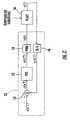
- FIG. 1is a diagrammatic representation of an apparatus constructed in accordance with the present invention for controlling the temperature of an electronic device under test
- FIG. 2is a block diagram illustrating the manner in which the apparatus of FIG. 1 functions as a closed loop system to maintain a predetermined temperature
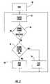
- FIG. 3is a flow diagram showing an additional open loop technique which can be used to further enhance the accuracy of the apparatus of FIG. 1 ;
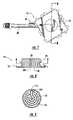
- FIG. 4is a side elevational view of a preferred embodiment of a thermal head assembly which can be utilized with the apparatus of FIG. 1 ;
- FIG. 5is a view top plan view of the thermal head assembly of FIG. 4 ;
- FIG. 6is an exploded view showing various parts of the thermal head assembly of FIG. 4 ;
- FIG. 7is a bottom plan view of the thermal head component of the assembly of FIG. 4 showing the temperature controlled surface thereof;
- FIG. 8is a cross sectional view taken along line 8 — 8 of FIG. 7 ;
- FIG. 9is a cross sectional view taken along line 9 — 9 of FIG. 8 .
- FIG. 1illustrates an apparatus for controlling the temperature of an electronic device 10 under test (“DUT”).
- device 10is an integrated circuit device mounted in a suitable test fixture 12 .
- Test fixture 12supplies the energy to power device 10 , as well as the various read/write commands by which the performance of device 10 is evaluated.
- thermal head 14has a temperature controlled surface 16 in thermal contact with device 10 .
- thermal head 14is attached to the end of a movable rod 18 which operates to move temperature controlled surface 16 into and out of engagement with device 10 (as indicated by arrow A).
- rod 18may form the piston rod of a pneumatic cylinder which is actuated to position thermal head 14 adjacent the device to be tested.
- thermocouple 20or other suitable sensor is provided at temperature controlled surface 16 to detect the temperature of device 10 .
- This informationis fed to a processor 22 for controlling the operation of thermal head 14 so as to maintain a predetermined temperature.
- the temperature to be maintainedis entered by a user at temperature selector 24 .
- processor 22 and temperature selector 24may be performed by a single digital computer or the like.
- Thermal head 14is preferably configured having both cooling and heating capability to accurately maintain a wide range of possible temperatures.
- thermal head 14has a cooled portion 26 situated between temperature controlled surface 16 and a heated portion 28 .
- Heated portion 28includes one or more heating elements 30 operative to supply thermal energy when the temperature of device 10 drops below the desired temperature.
- a suitable driver 32is controlled by processor 22 so as to supply the requisite power to operate heating element 30 .
- Cooled portion 26 of thermal head 14forms the evaporator of a refrigeration system also including a compressor 32 and a condenser 34 .
- the refrigeration systememploys a refrigerant fluid, such as R134a, circulated so as to alternately absorb and release thermal energy. This occurs when the refrigerant fluid changes between gaseous and liquid states in accordance with the well-known refrigeration cycle.
- the refrigerant fluidabsorbs excess thermal energy at the location of device 10 when refrigerant fluid “evaporates” from a liquid state to a gaseous state. This evaporation occurs in a fluid flow channel 36 defined in thermal head 14 .
- the low pressure gas exiting thermal head 14is then fed along pipe 38 to compressor 32 .
- the resulting high pressure gasis fed to condenser 34 by pipe 40 , where accumulated thermal energy dissipates.
- the refrigerant fluidis condensed to liquid form.
- High pressure liquid from condenser 34is fed back toward thermal head 14 along pipe 42 and capillary tube 44 .
- An “expansion valve”is formed in this case by the interface of capillary tube 44 and fluid flow channel 36 .
- the refrigerant in liquid formundergoes a pressure drop as it leaves the small inner diameter of capillary tube 44 and enters the larger enclosed volume at the inlet of flow channel 36 .
- This pressure dropcauses a reduction in temperature as predicted by the ideal gas law.
- the apparatus shown in FIG. 1is operative to maintain the selected temperature at temperature controlled surface 16 with high accuracy.
- this temperaturecan be easily controlled over a specified range within the ⁇ 3° C. requirement.
- the apparatusis capable of operating over a specified range between ⁇ 100° C. to +200° C. with an accuracy of ⁇ 0.5° C. in presently preferred embodiments.
- a metering valve 46is located operatively adjacent to thermal head 14 so as to regulate flow of refrigerant fluid into flow channel 36 .
- a metering valve 46utilizes a normally closed solenoid pulsing valve controlled by a pulse width modulated (PWM) signal.
- PWMpulse width modulated
- metering valve 46may be located within 18 inches of the inlet to flow channel 36 so as to regulate flow of refrigerant fluid thereto without substantial lag times.
- metering valve 46may be located at the inlet to capillary tube 44 .
- capillary tube 44will have a length of no more than about 12 inches. The relatively short length and small inner diameter of capillary tube 44 ensures a quick reaction time between operation of valve 44 and the temperature at temperature controlled surface 16 .
- Kryotech, Inc.the assignee of the present invention, has previously developed testing equipment in which the thermal head is configured as an evaporator in a refrigeration system. Refrigerant fluid passes to the thermal head in liquid form, where it is expanded. The resulting temperature drop absorbs thermal energy for the electronic device being tested so as to maintain a predetermined temperature.
- One such systemutilized a valve adjacent the outlet of the condenser operating under the control of a proportional controller.
- the compressor and condenserwere located several feet (e.g., 4–5 feet) away from the thermal head in the flow loop of the refrigerant fluid. In part because of the distant location of the valve, this system was capable of controlling the selected temperature only to an accuracy of about ⁇ 10° C.
- thermocouple 20provides a continuous temperature signal y(t) which is sampled and digitized, as indicated at 48 , to yield a sampled temperature signal y(kT). Signal y(kT) is then compared with an ideal temperature signal r(kT), as indicated at 50 , to produce an error signal e(kT).
- processor 22implements a control algorithm on error signal e(kT) to produce a correction signal u(kT).
- the control algorithmmay be a proportional plus integral plus derivative (PID) control algorithm as shown.
- the correction signal u(kT)is pulse width modulated, as indicated at 54 , or otherwise transformed to an appropriate analog signal u(t) for operation of the temperature control apparatus (or “plant”) 56 .
- the correction signal u(kT)may contain instructions for operation of both the system's cooling and heating capability.
- the closed loop system shown in FIG. 2is very effective at maintaining the desired temperature under steady state operating conditions.
- this systemwill sample the temperature signal and produce a desired correction signal at least once per second.
- the temperature at surface 16is sampled at least every 300 ms by this closed loop portion of the control system in presently preferred embodiments.
- processor 22preferably receives a signal 58 from test fixture 12 indicating the power consumption of electronic device 10 .
- FIG. 3illustrates one manner in which processor 22 may utilize the power signal from test fixture 12 .
- the instantaneous power consumption of device 10is sampled (as indicated at 62 ).
- processor 22preferably samples the power consumption many times per second. For example, the power consumption may be sampled 20–50 times per second or more in accordance with presently preferred embodiments of the present invention.
- the rate of change of power consumption(i.e., the first derivative of the power consumption) is then compared against a predetermined threshold (as indicated at 64 ). If the rate of change does not exceed the threshold, the process loops back for the next sample.
- processor 22determines whether the power consumption is increasing or decreasing (as indicated at 66 ). A positive power change indicates that the temperature of the electronic device will be increasing. Similarly, a negative power change indicates that the temperature of the electronic device will be decreasing. Action can be immediately taken to counteract these predicted temperature changes as they are occurring.
- the systemmay be activated into a full cooling mode (as indicated at 68 ) when the rate of power consumption exceeds the threshold in the positive direction.
- Full heating modecan be similarly activated (as indicated at 70 ) when the rate of power consumption exceeds the threshold in the negative direction.
- this open loop control systemwill maintain full cooling or heating just long enough to counteract the dramatic temperature change.
- the full “on” operation of either heating or coolingis maintained for about 200 milliseconds.
- the closed loop control systemwill then continue as usual to maintain the temperature of electronic device 10 .
- FIGS. 4–6illustrate a thermal head assembly 72 that may be used with the apparatus of FIG. 1 .
- assembly 72includes a thermal head 74 having a cooled portion 76 integrated with a heated portion 78 .
- Refrigerant fluidenters cooled portion 76 through capillary tube 80 and exits via outlet pipe 82 .
- heated portion 78defines a plurality of transverse holes 84 in which respective cartridge heaters are inserted. Leads from the thermocouple exit through a central vertical hole 86 .
- thermal head 74may be adapted to mate with the particular configuration of a socket cover 88 (which is part of the test fixture).
- socket cover 88includes a pair of upstanding aligning pins 90 . Pins 90 are received in the area between an adjacent pair of ears 92 located on the lower periphery of thermal head 74 .
- thermal head 74is received in a housing block 94 formed of a suitable insulative material, such as nylon 6/6.
- a gimbal assembly 96is attached to housing block 94 to facilitate even mating between thermal head 74 and the device under test.
- assembly 96includes a lower plate 98 and an upper plate 100 interconnected by a plurality of corner posts, such as post 102 .
- Each of the corner postsis surrounded by a helical spring such as spring 104 to normally urge plates 98 and 100 away from one another.
- a temperature controlled surface 106is defined on the bottom of thermal head 74 .
- Surface 106is preferably polished or otherwise configured so as to exhibit exceptional flatness and thus a relatively high reflectivity.
- the thermocoupleis received in a central hole 108 defined as shown in surface 106 .
- thermal head 74is preferably made of materials which exhibit high thermal conductivity. At the same time, thermal head 74 is configured to have low mass in order to allow rapid transfer of thermal energy.
- cooled portion 76may be formed of copper with heated portion 78 being formed of brass. The two pieces can be joined together such as by brazing to yield an integral structure.
- FIG. 9shows an exemplary flow channel 110 which can be defined in cooled portion 76 .
- refrigerant fluidenters through inlet 112 and moves along the serpentine pattern of flow channel 110 . Absorbed thermal energy causes the refrigerant to evaporate before exiting through outlet 114 .
- flow channel 110is formed by individual drilled holes that are connected along the length of the path.
- the present inventionprovides apparatus and methods for maintaining an electronic device under test at a selected temperature. Because the system uses a circulating refrigerant fluid instead of a liquid loop, the various disadvantages of liquid loop systems are eliminated. For example, there is no need for insulation of pipes as is required in a liquid loop system because all of the parts except the evaporator and suction tube back to the compressor remain at ambient temperature. For the same reason, many of the condensation issues presented by liquid loop designs are also eliminated. Set up time and energy efficiency are also improved in comparison with the prior art liquid loop systems.
Landscapes
- Engineering & Computer Science (AREA)
- Physics & Mathematics (AREA)
- Environmental & Geological Engineering (AREA)
- General Engineering & Computer Science (AREA)
- General Physics & Mathematics (AREA)
- Health & Medical Sciences (AREA)
- Toxicology (AREA)
- Automation & Control Theory (AREA)
- Mechanical Engineering (AREA)
- Thermal Sciences (AREA)
- Computer Hardware Design (AREA)
- Microelectronics & Electronic Packaging (AREA)
- Clinical Laboratory Science (AREA)
- Chemical & Material Sciences (AREA)
- Chemical Kinetics & Catalysis (AREA)
- Testing Of Individual Semiconductor Devices (AREA)
- Control Of Temperature (AREA)
Abstract
Description
Claims (38)
Priority Applications (1)
| Application Number | Priority Date | Filing Date | Title |
|---|---|---|---|
| US10/747,776US6993922B2 (en) | 2001-05-31 | 2003-12-29 | Apparatus and method for controlling the temperature of an electronic device under test |
Applications Claiming Priority (2)
| Application Number | Priority Date | Filing Date | Title |
|---|---|---|---|
| US09/871,526US6668570B2 (en) | 2001-05-31 | 2001-05-31 | Apparatus and method for controlling the temperature of an electronic device under test |
| US10/747,776US6993922B2 (en) | 2001-05-31 | 2003-12-29 | Apparatus and method for controlling the temperature of an electronic device under test |
Related Parent Applications (1)
| Application Number | Title | Priority Date | Filing Date |
|---|---|---|---|
| US09/871,526ContinuationUS6668570B2 (en) | 2001-05-31 | 2001-05-31 | Apparatus and method for controlling the temperature of an electronic device under test |
Publications (2)
| Publication Number | Publication Date |
|---|---|
| US20040139756A1 US20040139756A1 (en) | 2004-07-22 |
| US6993922B2true US6993922B2 (en) | 2006-02-07 |
Family
ID=25357649
Family Applications (2)
| Application Number | Title | Priority Date | Filing Date |
|---|---|---|---|
| US09/871,526Expired - LifetimeUS6668570B2 (en) | 2001-05-31 | 2001-05-31 | Apparatus and method for controlling the temperature of an electronic device under test |
| US10/747,776Expired - LifetimeUS6993922B2 (en) | 2001-05-31 | 2003-12-29 | Apparatus and method for controlling the temperature of an electronic device under test |
Family Applications Before (1)
| Application Number | Title | Priority Date | Filing Date |
|---|---|---|---|
| US09/871,526Expired - LifetimeUS6668570B2 (en) | 2001-05-31 | 2001-05-31 | Apparatus and method for controlling the temperature of an electronic device under test |
Country Status (7)
| Country | Link |
|---|---|
| US (2) | US6668570B2 (en) |
| EP (1) | EP1397625A1 (en) |
| JP (1) | JP2004527764A (en) |
| KR (2) | KR20040016872A (en) |
| CN (1) | CN1537217A (en) |
| CR (1) | CR7176A (en) |
| WO (1) | WO2002097342A1 (en) |
Cited By (17)
| Publication number | Priority date | Publication date | Assignee | Title |
|---|---|---|---|---|
| US20070081296A1 (en)* | 2005-10-11 | 2007-04-12 | Applied Materials, Inc. | Method of operating a capacitively coupled plasma reactor with dual temperature control loops |
| US20070081295A1 (en)* | 2005-10-11 | 2007-04-12 | Applied Materials, Inc. | Capacitively coupled plasma reactor having a cooled/heated wafer support with uniform temperature distribution |
| US20070091541A1 (en)* | 2005-10-20 | 2007-04-26 | Applied Materials, Inc. | Method of processing a workpiece in a plasma reactor using feed forward thermal control |
| US20070097580A1 (en)* | 2005-10-11 | 2007-05-03 | Applied Materials, Inc. | Method of cooling a wafer support at a uniform temperature in a capacitively coupled plasma reactor |
| US20070267188A1 (en)* | 2006-05-18 | 2007-11-22 | Centipede Systems, Inc. | Method and apparatus for setting and controlling temperature |
| US20070288823A1 (en)* | 2006-05-15 | 2007-12-13 | Centipede Systems, Inc. | Apparatus including a fluid coupler interfaced to a test head |
| US20080223555A1 (en)* | 2007-03-16 | 2008-09-18 | Centipede Systems, Inc. | Method and apparatus for controlling temperature |
| US7457117B2 (en)* | 2006-08-16 | 2008-11-25 | Rambus Inc. | System for controlling the temperature of electronic devices |
| US7661276B1 (en) | 2006-06-12 | 2010-02-16 | EADS North America, Inc. | Evaporator |
| US20100218692A1 (en)* | 2005-09-09 | 2010-09-02 | Seiko Epson Corporation | Temperature control unit for electronic component and handler apparatus |
| US20100303680A1 (en)* | 2005-10-11 | 2010-12-02 | Buchberger Douglas A Jr | Capacitively coupled plasma reactor having very agile wafer temperature control |
| US20110041532A1 (en)* | 2009-08-18 | 2011-02-24 | Preston Philip K | Low-Noise Fan Control for Refrigeration Cycle |
| US20110083837A1 (en)* | 2009-10-14 | 2011-04-14 | Tokyo Electron Limited | Temperature control system and temperature control method for substrate mounting table |
| US20130268117A1 (en)* | 2010-12-01 | 2013-10-10 | Abb Ag | Robot manipulator system |
| TWI487923B (en)* | 2013-06-18 | 2015-06-11 | Chroma Ate Inc | Test the temperature control module |
| TWI611193B (en)* | 2016-10-25 | 2018-01-11 | 致茂電子股份有限公司 | Anti-mist module for socket and electronic device testing apparatus provided with the same |
| US9921265B2 (en) | 2015-12-18 | 2018-03-20 | Sensata Technologies, Inc. | Thermal clutch for thermal control unit and methods related thereto |
Families Citing this family (85)
| Publication number | Priority date | Publication date | Assignee | Title |
|---|---|---|---|---|
| US7441133B2 (en)* | 2002-10-15 | 2008-10-21 | Microsemi Corp. - Analog Mixed Signal Group Ltd. | Rack level power management for power over Ethernet |
| US7017358B2 (en)* | 2003-03-19 | 2006-03-28 | Delta Design, Inc. | Apparatus and method for controlling the temperature of an electronic device |
| US6975028B1 (en) | 2003-03-19 | 2005-12-13 | Delta Design, Inc. | Thermal apparatus for engaging electronic device |
| DE602004031311D1 (en)* | 2003-08-18 | 2011-03-17 | Advantest Corp | Temperature control device |
| JP2007507899A (en)* | 2003-10-01 | 2007-03-29 | デルタ デザイン インコーポレーティッド | Electronic device temperature control apparatus and method |
| US7355428B2 (en)* | 2004-01-14 | 2008-04-08 | Delta Design, Inc. | Active thermal control system with miniature liquid-cooled temperature control device for electronic device testing |
| US7199597B2 (en) | 2004-02-16 | 2007-04-03 | Delta Design, Inc. | Dual feedback control system for maintaining the temperature of an IC-chip near a set-point |
| US20050189342A1 (en)* | 2004-02-23 | 2005-09-01 | Samer Kabbani | Miniature fluid-cooled heat sink with integral heater |
| US7123037B2 (en)* | 2004-02-27 | 2006-10-17 | Wells-Cti, Llc | Integrated circuit temperature sensing device and method |
| US7042240B2 (en)* | 2004-02-27 | 2006-05-09 | Wells-Cti, Llc | Burn-in testing apparatus and method |
| US7394271B2 (en)* | 2004-02-27 | 2008-07-01 | Wells-Cti, Llc | Temperature sensing and prediction in IC sockets |
| US20060290370A1 (en)* | 2004-02-27 | 2006-12-28 | Wells-Cti, Llc, An Oregon Limited Liability Company | Temperature control in ic sockets |
| US7301773B2 (en)* | 2004-06-04 | 2007-11-27 | Cooligy Inc. | Semi-compliant joining mechanism for semiconductor cooling applications |
| ATE395566T1 (en)* | 2004-06-10 | 2008-05-15 | Micheletti Impianti S R L | REFRIGERANT SYSTEM |
| EP1866656A2 (en)* | 2005-03-08 | 2007-12-19 | Wells-CTI, Llc. | Temperature sensing and prediction in ic sockets |
| JP4645373B2 (en)* | 2005-09-07 | 2011-03-09 | セイコーエプソン株式会社 | Electronic component temperature control device and handler device |
| US7515418B2 (en)* | 2005-09-26 | 2009-04-07 | Curtiss-Wright Controls, Inc. | Adjustable height liquid cooler in liquid flow through plate |
| US20080029248A1 (en)* | 2006-03-13 | 2008-02-07 | Sage Science, Inc. | Laboratory Temperature Control With Ultra-Smooth Heat Transfer Surfaces |
| DE102006015365B4 (en)* | 2006-04-03 | 2009-11-19 | Multitest Elektronische Systeme Gmbh | Method and device for tempering electronic components |
| US7498831B2 (en)* | 2006-04-05 | 2009-03-03 | Raytheon Company | Conduction-cooled accelerated test fixture |
| JP5228170B2 (en)* | 2006-04-18 | 2013-07-03 | 株式会社 Synax | Temperature control device |
| US20070240870A1 (en)* | 2006-04-18 | 2007-10-18 | Daytona Control Co., Ltd. | Temperature control apparatus |
| SG136816A1 (en)* | 2006-04-18 | 2007-11-29 | Daytona Control Co Ltd | Temperature control apparatus |
| JP4564973B2 (en) | 2007-01-26 | 2010-10-20 | 株式会社日立ハイテクノロジーズ | Plasma processing equipment |
| KR101153734B1 (en) | 2007-02-23 | 2012-06-08 | 가부시키가이샤 어드밴티스트 | Device for pressing electronic component and device for testing electronic component |
| CN101495819B (en)* | 2007-07-30 | 2011-08-17 | 株式会社爱德万测试 | Heat control device for electronic equipment |
| WO2009035459A1 (en) | 2007-09-14 | 2009-03-19 | Advantest Corporation | Advanced thermal control interface |
| US20110197609A1 (en)* | 2007-10-16 | 2011-08-18 | Kim Tiow Ooi | heat transfer system and method |
| US8424594B2 (en)* | 2007-12-10 | 2013-04-23 | Presto Engineering, Inc. | Apparatus for thermal control in the analysis of electronic devices |
| US20090267631A1 (en)* | 2008-04-24 | 2009-10-29 | Honeywell International Inc. | Large Component Thermal Head Adapter |
| CN101387678B (en)* | 2008-10-28 | 2011-07-06 | 海信科龙电器股份有限公司 | A test device and test method for a semiconductor refrigeration component |
| JP2010151794A (en)* | 2008-11-27 | 2010-07-08 | Panasonic Corp | Electronic component tester |
| JP4978653B2 (en)* | 2009-04-10 | 2012-07-18 | セイコーエプソン株式会社 | Electronic component temperature control device and handler device |
| US9347987B2 (en)* | 2009-11-06 | 2016-05-24 | Intel Corporation | Direct liquid-contact micro-channel heat transfer devices, methods of temperature control for semiconductive devices, and processes of forming same |
| DE102010005275A1 (en)* | 2010-01-21 | 2011-07-28 | Thermozyklus GmbH & Co. KG, 82131 | Method and device for setting a tempering device |
| US8643392B2 (en) | 2011-04-01 | 2014-02-04 | Incavo Otax, Inc. | Pneumatically actuated IC socket with integrated heat sink |
| KR20130031945A (en)* | 2011-09-22 | 2013-04-01 | 삼성전자주식회사 | Apparatus for controlling temperature of loading chuck and method of controlling temperature |
| CN102393768A (en)* | 2011-10-13 | 2012-03-28 | 清华大学 | Temperature closed-loop control device and testing method |
| GB201118339D0 (en)* | 2011-10-24 | 2011-12-07 | Cambridge Reactor Design Ltd | Heating and cooling apparatus |
| WO2015025307A1 (en) | 2013-08-22 | 2015-02-26 | M.D. Mechanical Devices Ltd. | Efficient temperature forcing of semiconductor devices under test |
| US9736962B2 (en)* | 2012-02-27 | 2017-08-15 | M.D. Mechanical Devices Ltd. | Efficient temperature forcing of semiconductor devices under test |
| US9677822B2 (en)* | 2012-02-27 | 2017-06-13 | M.D. Mechanical Devices Ltd. | Efficient temperature forcing of semiconductor devices under test |
| JP2012185184A (en)* | 2012-07-02 | 2012-09-27 | Seiko Epson Corp | Temperature control apparatus of electronic component, and handler apparatus |
| SG11201504629YA (en)* | 2012-12-12 | 2015-07-30 | Marvelous Technology Pte Ltd | Thermal head for device under test and method for controlling the temperature of device under test |
| US9709622B2 (en)* | 2013-03-15 | 2017-07-18 | Sensata Technologies, Inc. | Direct injection phase change temperature control system |
| JP6277777B2 (en)* | 2014-02-27 | 2018-02-14 | 富士通株式会社 | Air conditioning control system and air conditioning control method |
| DE102014224669A1 (en)* | 2014-12-02 | 2016-06-02 | BSH Hausgeräte GmbH | Refrigerating appliance with a heating circuit |
| US10288361B2 (en)* | 2015-03-17 | 2019-05-14 | Hatco Corporation | Hot and cold shelf assembly with replaceable heating elements |
| JP6597059B2 (en)* | 2015-08-27 | 2019-10-30 | セイコーエプソン株式会社 | Electronic component conveying device and electronic component inspection device |
| US11280827B2 (en)* | 2016-02-29 | 2022-03-22 | Teradyne, Inc. | Thermal control of a probe card assembly |
| US20170261547A1 (en)* | 2016-03-08 | 2017-09-14 | Temptronic Corporation | Temperature Forcing System and Method with Conductive Thermal Probes |
| TWI597508B (en)* | 2016-07-22 | 2017-09-01 | 致茂電子股份有限公司 | Temperature control module for electronic devices and testing apparatus provided with the same |
| US10126359B2 (en)* | 2017-01-12 | 2018-11-13 | Sensata Technologies | Free piston stirling cooler temperature control system for semiconductor test |
| JP7316799B2 (en)* | 2019-01-30 | 2023-07-28 | 株式会社アドバンテスト | Electronic component handling equipment and electronic component testing equipment |
| JP7316798B2 (en)* | 2019-01-30 | 2023-07-28 | 株式会社アドバンテスト | Electronic component handling equipment and electronic component testing equipment |
| IT201900006974A1 (en)* | 2019-05-17 | 2020-11-17 | Eles Semiconductor Equipment S P A | Thermal conditioning of electronic devices under test based on extensible elements |
| JP7143246B2 (en)* | 2019-05-23 | 2022-09-28 | 株式会社アドバンテスト | Electronic component handling equipment and electronic component testing equipment |
| US11493551B2 (en) | 2020-06-22 | 2022-11-08 | Advantest Test Solutions, Inc. | Integrated test cell using active thermal interposer (ATI) with parallel socket actuation |
| JP2023536607A (en)* | 2020-08-04 | 2023-08-28 | 株式会社アドバンテスト | Handler, automatic test equipment and method for testing a device under test using test site specific signaling |
| US11549981B2 (en) | 2020-10-01 | 2023-01-10 | Advantest Test Solutions, Inc. | Thermal solution for massively parallel testing |
| US11808812B2 (en) | 2020-11-02 | 2023-11-07 | Advantest Test Solutions, Inc. | Passive carrier-based device delivery for slot-based high-volume semiconductor test system |
| US11821913B2 (en) | 2020-11-02 | 2023-11-21 | Advantest Test Solutions, Inc. | Shielded socket and carrier for high-volume test of semiconductor devices |
| US12320841B2 (en) | 2020-11-19 | 2025-06-03 | Advantest Test Solutions, Inc. | Wafer scale active thermal interposer for device testing |
| US11567119B2 (en) | 2020-12-04 | 2023-01-31 | Advantest Test Solutions, Inc. | Testing system including active thermal interposer device |
| US11573262B2 (en) | 2020-12-31 | 2023-02-07 | Advantest Test Solutions, Inc. | Multi-input multi-zone thermal control for device testing |
| CN112578257B (en)* | 2021-02-26 | 2021-06-01 | 杭州长川科技股份有限公司 | Temperature control testing device and testing equipment |
| US11587640B2 (en) | 2021-03-08 | 2023-02-21 | Advantest Test Solutions, Inc. | Carrier based high volume system level testing of devices with pop structures |
| CN113467546A (en)* | 2021-07-26 | 2021-10-01 | 珠海格力电器股份有限公司 | Temperature control method and device and temperature measurement box |
| US12235314B2 (en) | 2021-09-14 | 2025-02-25 | Advantest Test Solutions, Inc | Parallel test cell with self actuated sockets |
| US11656273B1 (en) | 2021-11-05 | 2023-05-23 | Advantest Test Solutions, Inc. | High current device testing apparatus and systems |
| CN118265883A (en)* | 2022-01-24 | 2024-06-28 | Lti控股公司 | System and method for controlling expansion valve flow and compressor speed of a refrigeration circuit under conditions of rapid changes in heat load |
| US11835549B2 (en) | 2022-01-26 | 2023-12-05 | Advantest Test Solutions, Inc. | Thermal array with gimbal features and enhanced thermal performance |
| US12411167B2 (en) | 2022-01-26 | 2025-09-09 | Advantest Test Solutions, Inc. | Tension-based socket gimbal for engaging device under test with thermal array |
| CN114791538B (en)* | 2022-03-25 | 2023-03-24 | 南通金通茂电子有限公司 | Full-automatic detection equipment for electronic materials |
| JP2023149981A (en)* | 2022-03-31 | 2023-10-16 | 株式会社アドバンテスト | Temperature adjustment device, electronic component handling device, electronic component testing device, and method for adjusting dut temperature |
| WO2024018536A1 (en)* | 2022-07-19 | 2024-01-25 | 株式会社アドバンテスト | Heat exchanger, electronic component handling device, and electronic component testing device |
| KR20240038259A (en)* | 2022-09-16 | 2024-03-25 | 주식회사 아테코 | A test board for semiconductor devices |
| US11828795B1 (en) | 2022-10-21 | 2023-11-28 | AEM Holdings Ltd. | Test system with a thermal head comprising a plurality of adapters for independent thermal control of zones |
| US11796589B1 (en) | 2022-10-21 | 2023-10-24 | AEM Holdings Ltd. | Thermal head for independent control of zones |
| IL320336A (en) | 2022-10-21 | 2025-06-01 | Aem Holdings Ltd | Thermal head for independent control of zones |
| US11656272B1 (en) | 2022-10-21 | 2023-05-23 | AEM Holdings Ltd. | Test system with a thermal head comprising a plurality of adapters and one or more cold plates for independent control of zones |
| US11693051B1 (en) | 2022-10-21 | 2023-07-04 | AEM Holdings Ltd. | Thermal head for independent control of zones |
| US11828796B1 (en) | 2023-05-02 | 2023-11-28 | AEM Holdings Ltd. | Integrated heater and temperature measurement |
| CN117330940B (en)* | 2023-11-20 | 2025-03-14 | 深圳市诺泰芯装备有限公司 | A low temperature test flow channel refrigeration device |
| US20250220857A1 (en)* | 2023-12-28 | 2025-07-03 | Intel Corporation | Vapor compression assisted liquid cooling system for electronic components |
Citations (38)
| Publication number | Priority date | Publication date | Assignee | Title |
|---|---|---|---|---|
| US3003332A (en) | 1957-10-07 | 1961-10-10 | John E Watkins | Control means for refrigerating system |
| US3757530A (en) | 1972-04-12 | 1973-09-11 | Control Data Corp | Cooling system for data processing apparatus |
| US3882691A (en) | 1971-06-10 | 1975-05-13 | Donald Baines | Apparatus for cooling electrical circuit components |
| US4745767A (en) | 1984-07-26 | 1988-05-24 | Sanyo Electric Co., Ltd. | System for controlling flow rate of refrigerant |
| US4807445A (en) | 1986-11-25 | 1989-02-28 | Nippondenso Co., Ltd. | Refrigeration system |
| US5125451A (en) | 1991-04-02 | 1992-06-30 | Microunity Systems Engineering, Inc. | Heat exchanger for solid-state electronic devices |
| US5151871A (en) | 1989-06-16 | 1992-09-29 | Tokyo Electron Limited | Method for heat-processing semiconductor device and apparatus for the same |
| US5164661A (en) | 1991-05-31 | 1992-11-17 | Ej Systems, Inc. | Thermal control system for a semi-conductor burn-in |
| US5196785A (en) | 1990-12-12 | 1993-03-23 | Hewlett-Packard Company | Tape automated bonding test apparatus for thermal, mechanical and electrical coupling |
| US5198753A (en) | 1990-06-29 | 1993-03-30 | Digital Equipment Corporation | Integrated circuit test fixture and method |
| US5271239A (en) | 1990-11-13 | 1993-12-21 | Rocky Research | Cooling apparatus for electronic and computer components |
| US5325052A (en) | 1990-11-30 | 1994-06-28 | Tokyo Electron Yamanashi Limited | Probe apparatus |
| US5365749A (en) | 1993-12-23 | 1994-11-22 | Ncr Corporation | Computer component cooling system with local evaporation of refrigerant |
| US5426952A (en) | 1994-03-03 | 1995-06-27 | General Electric Company | Refrigerant flow rate control based on evaporator exit dryness |
| US5574627A (en) | 1995-07-24 | 1996-11-12 | At&T Global Information Solutions Company | Apparatus for preventing the formation of condensation on sub-cooled integrated circuit devices |
| US5587880A (en) | 1995-06-28 | 1996-12-24 | Aavid Laboratories, Inc. | Computer cooling system operable under the force of gravity in first orientation and against the force of gravity in second orientation |
| US5821505A (en) | 1997-04-04 | 1998-10-13 | Unisys Corporation | Temperature control system for an electronic device which achieves a quick response by interposing a heater between the device and a heat sink |
| WO1998046059A1 (en) | 1997-04-04 | 1998-10-15 | Unisys Corporation | Temperature control system for an electronic device |
| US5847366A (en) | 1996-06-18 | 1998-12-08 | Intel Corporation | Apparatus and method for controlling the temperature of an integrated circuit under test |
| US5847293A (en) | 1995-12-04 | 1998-12-08 | Aetrium Incorporated | Test handler for DUT's |
| US5918469A (en) | 1996-01-11 | 1999-07-06 | Silicon Thermal, Inc. | Cooling system and method of cooling electronic devices |
| US5944093A (en) | 1997-12-30 | 1999-08-31 | Intel Corporation | Pickup chuck with an integral heat pipe |
| US5977785A (en) | 1996-05-28 | 1999-11-02 | Burward-Hoy; Trevor | Method and apparatus for rapidly varying the operating temperature of a semiconductor device in a testing environment |
| US6049217A (en) | 1997-12-30 | 2000-04-11 | Intel Corporation | Thermally enhanced test contactor |
| US6054676A (en) | 1998-02-09 | 2000-04-25 | Kryotech, Inc. | Method and apparatus for cooling an integrated circuit device |
| US6084215A (en) | 1997-11-05 | 2000-07-04 | Tokyo Electron Limited | Semiconductor wafer holder with spring-mounted temperature measurement apparatus disposed therein |
| US6104204A (en) | 1997-05-12 | 2000-08-15 | Advantest Corporation | Semiconductor device testing apparatus |
| US6147506A (en) | 1997-04-29 | 2000-11-14 | International Business Machines Corporation | Wafer test fixture using a biasing bladder and methodology |
| US6163163A (en) | 1998-09-14 | 2000-12-19 | Semitest, Inc. | Semiconductor material characterizing method and apparatus |
| US6184504B1 (en) | 1999-04-13 | 2001-02-06 | Silicon Thermal, Inc. | Temperature control system for electronic devices |
| US6246581B1 (en) | 1999-10-12 | 2001-06-12 | International Business Machines Corporation | Heated PCB interconnect for cooled IC chip modules |
| US6262584B1 (en) | 1999-03-31 | 2001-07-17 | Mcelectronics Co., Ltd. | IC device temperature control system and IC device inspection apparatus incorporating the same |
| US6297660B2 (en) | 1999-01-13 | 2001-10-02 | Micron Technology, Inc. | Test carrier with variable force applying mechanism for testing semiconductor components |
| US6349553B1 (en) | 1995-09-20 | 2002-02-26 | Sun Microsystems, Inc. | Method and system for cooling electrical components |
| US6415619B1 (en) | 2001-03-09 | 2002-07-09 | Hewlett-Packard Company | Multi-load refrigeration system with multiple parallel evaporators |
| US6476627B1 (en) | 1996-10-21 | 2002-11-05 | Delta Design, Inc. | Method and apparatus for temperature control of a device during testing |
| US6489793B2 (en) | 1996-10-21 | 2002-12-03 | Delta Design, Inc. | Temperature control of electronic devices using power following feedback |
| US6519955B2 (en) | 2000-04-04 | 2003-02-18 | Thermal Form & Function | Pumped liquid cooling system using a phase change refrigerant |
- 2001
- 2001-05-31USUS09/871,526patent/US6668570B2/ennot_activeExpired - Lifetime
- 2002
- 2002-05-29EPEP02752001Apatent/EP1397625A1/ennot_activeWithdrawn
- 2002-05-29KRKR10-2003-7015670Apatent/KR20040016872A/ennot_activeCeased
- 2002-05-29CNCNA028120574Apatent/CN1537217A/enactivePending
- 2002-05-29JPJP2003500481Apatent/JP2004527764A/enactivePending
- 2002-05-29WOPCT/US2002/016673patent/WO2002097342A1/enactiveApplication Filing
- 2002-05-29KRKR1020097006694Apatent/KR20090047556A/ennot_activeWithdrawn
- 2003
- 2003-12-01CRCR7176Apatent/CR7176A/enunknown
- 2003-12-29USUS10/747,776patent/US6993922B2/ennot_activeExpired - Lifetime
Patent Citations (40)
| Publication number | Priority date | Publication date | Assignee | Title |
|---|---|---|---|---|
| US3003332A (en) | 1957-10-07 | 1961-10-10 | John E Watkins | Control means for refrigerating system |
| US3882691A (en) | 1971-06-10 | 1975-05-13 | Donald Baines | Apparatus for cooling electrical circuit components |
| US3757530A (en) | 1972-04-12 | 1973-09-11 | Control Data Corp | Cooling system for data processing apparatus |
| US4745767A (en) | 1984-07-26 | 1988-05-24 | Sanyo Electric Co., Ltd. | System for controlling flow rate of refrigerant |
| US4807445A (en) | 1986-11-25 | 1989-02-28 | Nippondenso Co., Ltd. | Refrigeration system |
| US5151871A (en) | 1989-06-16 | 1992-09-29 | Tokyo Electron Limited | Method for heat-processing semiconductor device and apparatus for the same |
| US5198753A (en) | 1990-06-29 | 1993-03-30 | Digital Equipment Corporation | Integrated circuit test fixture and method |
| US5271239A (en) | 1990-11-13 | 1993-12-21 | Rocky Research | Cooling apparatus for electronic and computer components |
| US5325052A (en) | 1990-11-30 | 1994-06-28 | Tokyo Electron Yamanashi Limited | Probe apparatus |
| US5196785A (en) | 1990-12-12 | 1993-03-23 | Hewlett-Packard Company | Tape automated bonding test apparatus for thermal, mechanical and electrical coupling |
| US5125451A (en) | 1991-04-02 | 1992-06-30 | Microunity Systems Engineering, Inc. | Heat exchanger for solid-state electronic devices |
| US5164661A (en) | 1991-05-31 | 1992-11-17 | Ej Systems, Inc. | Thermal control system for a semi-conductor burn-in |
| US5365749A (en) | 1993-12-23 | 1994-11-22 | Ncr Corporation | Computer component cooling system with local evaporation of refrigerant |
| US5426952A (en) | 1994-03-03 | 1995-06-27 | General Electric Company | Refrigerant flow rate control based on evaporator exit dryness |
| US5587880A (en) | 1995-06-28 | 1996-12-24 | Aavid Laboratories, Inc. | Computer cooling system operable under the force of gravity in first orientation and against the force of gravity in second orientation |
| US5574627A (en) | 1995-07-24 | 1996-11-12 | At&T Global Information Solutions Company | Apparatus for preventing the formation of condensation on sub-cooled integrated circuit devices |
| US6349553B1 (en) | 1995-09-20 | 2002-02-26 | Sun Microsystems, Inc. | Method and system for cooling electrical components |
| US5847293A (en) | 1995-12-04 | 1998-12-08 | Aetrium Incorporated | Test handler for DUT's |
| US5918469A (en) | 1996-01-11 | 1999-07-06 | Silicon Thermal, Inc. | Cooling system and method of cooling electronic devices |
| US5977785A (en) | 1996-05-28 | 1999-11-02 | Burward-Hoy; Trevor | Method and apparatus for rapidly varying the operating temperature of a semiconductor device in a testing environment |
| US5847366A (en) | 1996-06-18 | 1998-12-08 | Intel Corporation | Apparatus and method for controlling the temperature of an integrated circuit under test |
| US6489793B2 (en) | 1996-10-21 | 2002-12-03 | Delta Design, Inc. | Temperature control of electronic devices using power following feedback |
| US6476627B1 (en) | 1996-10-21 | 2002-11-05 | Delta Design, Inc. | Method and apparatus for temperature control of a device during testing |
| US5821505A (en) | 1997-04-04 | 1998-10-13 | Unisys Corporation | Temperature control system for an electronic device which achieves a quick response by interposing a heater between the device and a heat sink |
| EP0994645A2 (en) | 1997-04-04 | 2000-04-19 | Unisys Corporation | Temperature control system for an electronic device in which device temperature is estimated from heater temperature and heat sink temperature |
| WO1998046059A1 (en) | 1997-04-04 | 1998-10-15 | Unisys Corporation | Temperature control system for an electronic device |
| US6147506A (en) | 1997-04-29 | 2000-11-14 | International Business Machines Corporation | Wafer test fixture using a biasing bladder and methodology |
| US6104204A (en) | 1997-05-12 | 2000-08-15 | Advantest Corporation | Semiconductor device testing apparatus |
| US6084215A (en) | 1997-11-05 | 2000-07-04 | Tokyo Electron Limited | Semiconductor wafer holder with spring-mounted temperature measurement apparatus disposed therein |
| US5944093A (en) | 1997-12-30 | 1999-08-31 | Intel Corporation | Pickup chuck with an integral heat pipe |
| US6049217A (en) | 1997-12-30 | 2000-04-11 | Intel Corporation | Thermally enhanced test contactor |
| US6054676A (en) | 1998-02-09 | 2000-04-25 | Kryotech, Inc. | Method and apparatus for cooling an integrated circuit device |
| US6163163A (en) | 1998-09-14 | 2000-12-19 | Semitest, Inc. | Semiconductor material characterizing method and apparatus |
| US6297660B2 (en) | 1999-01-13 | 2001-10-02 | Micron Technology, Inc. | Test carrier with variable force applying mechanism for testing semiconductor components |
| US6262584B1 (en) | 1999-03-31 | 2001-07-17 | Mcelectronics Co., Ltd. | IC device temperature control system and IC device inspection apparatus incorporating the same |
| US6184504B1 (en) | 1999-04-13 | 2001-02-06 | Silicon Thermal, Inc. | Temperature control system for electronic devices |
| US6246581B1 (en) | 1999-10-12 | 2001-06-12 | International Business Machines Corporation | Heated PCB interconnect for cooled IC chip modules |
| US6519955B2 (en) | 2000-04-04 | 2003-02-18 | Thermal Form & Function | Pumped liquid cooling system using a phase change refrigerant |
| US6679081B2 (en) | 2000-04-04 | 2004-01-20 | Thermal Form & Function, Llc | Pumped liquid cooling system using a phase change refrigerant |
| US6415619B1 (en) | 2001-03-09 | 2002-07-09 | Hewlett-Packard Company | Multi-load refrigeration system with multiple parallel evaporators |
Cited By (54)
| Publication number | Priority date | Publication date | Assignee | Title |
|---|---|---|---|---|
| US20100218692A1 (en)* | 2005-09-09 | 2010-09-02 | Seiko Epson Corporation | Temperature control unit for electronic component and handler apparatus |
| US8272230B2 (en) | 2005-09-09 | 2012-09-25 | Seiko Epson Corporation | Temperature control unit for electronic component and handler apparatus |
| US20100303680A1 (en)* | 2005-10-11 | 2010-12-02 | Buchberger Douglas A Jr | Capacitively coupled plasma reactor having very agile wafer temperature control |
| US20070081296A1 (en)* | 2005-10-11 | 2007-04-12 | Applied Materials, Inc. | Method of operating a capacitively coupled plasma reactor with dual temperature control loops |
| US8092638B2 (en) | 2005-10-11 | 2012-01-10 | Applied Materials Inc. | Capacitively coupled plasma reactor having a cooled/heated wafer support with uniform temperature distribution |
| US8034180B2 (en) | 2005-10-11 | 2011-10-11 | Applied Materials, Inc. | Method of cooling a wafer support at a uniform temperature in a capacitively coupled plasma reactor |
| US8157951B2 (en) | 2005-10-11 | 2012-04-17 | Applied Materials, Inc. | Capacitively coupled plasma reactor having very agile wafer temperature control |
| US7988872B2 (en) | 2005-10-11 | 2011-08-02 | Applied Materials, Inc. | Method of operating a capacitively coupled plasma reactor with dual temperature control loops |
| US20070097580A1 (en)* | 2005-10-11 | 2007-05-03 | Applied Materials, Inc. | Method of cooling a wafer support at a uniform temperature in a capacitively coupled plasma reactor |
| US20070081295A1 (en)* | 2005-10-11 | 2007-04-12 | Applied Materials, Inc. | Capacitively coupled plasma reactor having a cooled/heated wafer support with uniform temperature distribution |
| US8337660B2 (en) | 2005-10-11 | 2012-12-25 | B/E Aerospace, Inc. | Capacitively coupled plasma reactor having very agile wafer temperature control |
| US20100300621A1 (en)* | 2005-10-11 | 2010-12-02 | Paul Lukas Brillhart | Method of cooling a wafer support at a uniform temperature in a capacitively coupled plasma reactor |
| US8801893B2 (en)* | 2005-10-11 | 2014-08-12 | Be Aerospace, Inc. | Method of cooling a wafer support at a uniform temperature in a capacitively coupled plasma reactor |
| US8221580B2 (en) | 2005-10-20 | 2012-07-17 | Applied Materials, Inc. | Plasma reactor with wafer backside thermal loop, two-phase internal pedestal thermal loop and a control processor governing both loops |
| US20110068085A1 (en)* | 2005-10-20 | 2011-03-24 | Paul Lukas Brillhart | Method of processing a workpiece in a plasma reactor using multiple zone feed forward thermal control |
| US8980044B2 (en) | 2005-10-20 | 2015-03-17 | Be Aerospace, Inc. | Plasma reactor with a multiple zone thermal control feed forward control apparatus |
| US8329586B2 (en) | 2005-10-20 | 2012-12-11 | Applied Materials, Inc. | Method of processing a workpiece in a plasma reactor using feed forward thermal control |
| US20100314046A1 (en)* | 2005-10-20 | 2010-12-16 | Paul Lukas Brillhart | Plasma reactor with a multiple zone thermal control feed forward control apparatus |
| US20070089834A1 (en)* | 2005-10-20 | 2007-04-26 | Applied Materials, Inc. | Plasma reactor with a multiple zone thermal control feed forward control apparatus |
| US8608900B2 (en) | 2005-10-20 | 2013-12-17 | B/E Aerospace, Inc. | Plasma reactor with feed forward thermal control system using a thermal model for accommodating RF power changes or wafer temperature changes |
| US20100319851A1 (en)* | 2005-10-20 | 2010-12-23 | Buchberger Jr Douglas A | Plasma reactor with feed forward thermal control system using a thermal model for accommodating rf power changes or wafer temperature changes |
| US20110065279A1 (en)* | 2005-10-20 | 2011-03-17 | Buchberger Jr Douglas A | Method of processing a workpiece in a plasma reactor using feed forward thermal control |
| US20070091541A1 (en)* | 2005-10-20 | 2007-04-26 | Applied Materials, Inc. | Method of processing a workpiece in a plasma reactor using feed forward thermal control |
| US8546267B2 (en) | 2005-10-20 | 2013-10-01 | B/E Aerospace, Inc. | Method of processing a workpiece in a plasma reactor using multiple zone feed forward thermal control |
| US20070091538A1 (en)* | 2005-10-20 | 2007-04-26 | Buchberger Douglas A Jr | Plasma reactor with wafer backside thermal loop, two-phase internal pedestal thermal loop and a control processor governing both loops |
| US8012304B2 (en) | 2005-10-20 | 2011-09-06 | Applied Materials, Inc. | Plasma reactor with a multiple zone thermal control feed forward control apparatus |
| US8021521B2 (en) | 2005-10-20 | 2011-09-20 | Applied Materials, Inc. | Method for agile workpiece temperature control in a plasma reactor using a thermal model |
| US20070091539A1 (en)* | 2005-10-20 | 2007-04-26 | Applied Materials, Inc. | Plasma reactor with feed forward thermal control system using a thermal model for accommodating RF power changes or wafer temperature changes |
| US20070091537A1 (en)* | 2005-10-20 | 2007-04-26 | Applied Materials, Inc. | Method for agile workpiece temperature control in a plasma reactor using a thermal model |
| US8092639B2 (en) | 2005-10-20 | 2012-01-10 | Advanced Thermal Sciences Corporation | Plasma reactor with feed forward thermal control system using a thermal model for accommodating RF power changes or wafer temperature changes |
| US20070091540A1 (en)* | 2005-10-20 | 2007-04-26 | Applied Materials, Inc. | Method of processing a workpiece in a plasma reactor using multiple zone feed forward thermal control |
| US7870800B2 (en) | 2006-05-15 | 2011-01-18 | Centipede Systems, Inc. | Apparatus including a fluid coupler interfaced to a test head |
| US20070288823A1 (en)* | 2006-05-15 | 2007-12-13 | Centipede Systems, Inc. | Apparatus including a fluid coupler interfaced to a test head |
| US8025097B2 (en) | 2006-05-18 | 2011-09-27 | Centipede Systems, Inc. | Method and apparatus for setting and controlling temperature |
| US20070267188A1 (en)* | 2006-05-18 | 2007-11-22 | Centipede Systems, Inc. | Method and apparatus for setting and controlling temperature |
| US7661276B1 (en) | 2006-06-12 | 2010-02-16 | EADS North America, Inc. | Evaporator |
| US7457117B2 (en)* | 2006-08-16 | 2008-11-25 | Rambus Inc. | System for controlling the temperature of electronic devices |
| US20150377570A1 (en)* | 2007-03-16 | 2015-12-31 | Centipede Systems, Inc. | Apparatus to Control Device Temperature Utilizing Multiple Thermal Paths |
| US8151872B2 (en) | 2007-03-16 | 2012-04-10 | Centipede Systems, Inc. | Method and apparatus for controlling temperature |
| US10119776B2 (en)* | 2007-03-16 | 2018-11-06 | Centipede Systems, Inc. | Apparatus to control device temperature utilizing multiple thermal paths |
| US20080223555A1 (en)* | 2007-03-16 | 2008-09-18 | Centipede Systems, Inc. | Method and apparatus for controlling temperature |
| US20130068442A1 (en)* | 2007-03-16 | 2013-03-21 | Centipede Systems, Inc. | Method and Apparatus for Controlling Temperature |
| US9151551B2 (en)* | 2007-03-16 | 2015-10-06 | Centipede Systems, Inc. | Apparatus to control device temperature utilizing multiple thermal paths |
| US20110041532A1 (en)* | 2009-08-18 | 2011-02-24 | Preston Philip K | Low-Noise Fan Control for Refrigeration Cycle |
| US8375733B2 (en) | 2009-08-18 | 2013-02-19 | Polyscience | Low-noise fan control for refrigeration cycle |
| US20110083837A1 (en)* | 2009-10-14 | 2011-04-14 | Tokyo Electron Limited | Temperature control system and temperature control method for substrate mounting table |
| US8950469B2 (en)* | 2009-10-14 | 2015-02-10 | Tokyo Electron Limited | Temperature control system and temperature control method for substrate mounting table |
| US9085084B2 (en)* | 2010-12-01 | 2015-07-21 | Abb Ag | Robot manipulator system |
| US20130268117A1 (en)* | 2010-12-01 | 2013-10-10 | Abb Ag | Robot manipulator system |
| TWI487923B (en)* | 2013-06-18 | 2015-06-11 | Chroma Ate Inc | Test the temperature control module |
| US9353995B2 (en) | 2013-06-18 | 2016-05-31 | Chroma Ate Inc. | Temperature control module for a socket |
| US9921265B2 (en) | 2015-12-18 | 2018-03-20 | Sensata Technologies, Inc. | Thermal clutch for thermal control unit and methods related thereto |
| TWI611193B (en)* | 2016-10-25 | 2018-01-11 | 致茂電子股份有限公司 | Anti-mist module for socket and electronic device testing apparatus provided with the same |
| US10520528B2 (en) | 2016-10-25 | 2019-12-31 | Chroma Ate Inc. | Dew resistant module for test socket and electronic component testing device having the same |
Also Published As
| Publication number | Publication date |
|---|---|
| KR20040016872A (en) | 2004-02-25 |
| KR20090047556A (en) | 2009-05-12 |
| EP1397625A1 (en) | 2004-03-17 |
| CR7176A (en) | 2004-06-08 |
| CN1537217A (en) | 2004-10-13 |
| JP2004527764A (en) | 2004-09-09 |
| US20040139756A1 (en) | 2004-07-22 |
| WO2002097342A1 (en) | 2002-12-05 |
| US6668570B2 (en) | 2003-12-30 |
| US20030217558A1 (en) | 2003-11-27 |
Similar Documents
| Publication | Publication Date | Title |
|---|---|---|
| US6993922B2 (en) | Apparatus and method for controlling the temperature of an electronic device under test | |
| US7100389B1 (en) | Apparatus and method having mechanical isolation arrangement for controlling the temperature of an electronic device under test | |
| US6975028B1 (en) | Thermal apparatus for engaging electronic device | |
| US4688390A (en) | Refrigerant control for multiple heat exchangers | |
| US7007506B2 (en) | Refrigeration system utilizing incomplete evaporation of refrigerant in evaporator | |
| US8950206B2 (en) | Compressor assembly having electronics cooling system and method | |
| US9736962B2 (en) | Efficient temperature forcing of semiconductor devices under test | |
| US9677822B2 (en) | Efficient temperature forcing of semiconductor devices under test | |
| TWI278977B (en) | Cooling equipment | |
| WO2003010646A1 (en) | Integrated circuit cooling apparatus | |
| EP1709373B1 (en) | Transcritical vapor compression optimization through maximization of heating capacity | |
| KR20080022543A (en) | Cooling system controls and methods | |
| US7370485B2 (en) | Performance testing apparatus of refrigerating cycle | |
| US6988546B1 (en) | Sample temperature regulator | |
| JP3662238B2 (en) | Cooling device and thermostatic device | |
| US7062934B2 (en) | Apparatus and method for controlling the temperature of an electronic device | |
| JPH11151223A (en) | Regulator for regulating flow rate and method therefor | |
| CN219415274U (en) | Outdoor unit and air conditioning system | |
| CN220524254U (en) | air conditioner | |
| US3585809A (en) | Absorption refrigeration machine | |
| JP3427285B2 (en) | Absorption chiller / heater | |
| JP2019521307A (en) | Electronic expansion valve with multiple orifice plates | |
| US20060123816A1 (en) | Float for refrigerator system with float valve control | |
| JP2000249409A (en) | Flow rate control method of non-azeotropic mixed refrigerant in cooler | |
| CN109900002A (en) | Heating, ventilation, air-conditioning and the refrigeration system of ability are stabilized with mass flow |
Legal Events
| Date | Code | Title | Description |
|---|---|---|---|
| AS | Assignment | Owner name:ADVANTEST CORPORATION, JAPAN Free format text:LICENSE AGREEMENT;ASSIGNOR:KYROTEC, INC.;REEL/FRAME:016091/0816 Effective date:20031115 | |
| AS | Assignment | Owner name:ADVANTEST CORPORATION, JAPAN Free format text:LICENSE AGREEMENT;ASSIGNOR:KRYOTEC, INC.;REEL/FRAME:016111/0823 Effective date:20031115 | |
| AS | Assignment | Owner name:DELTA DESIGN, INC., CALIFORNIA Free format text:ASSIGNMENT OF ASSIGNORS INTEREST;ASSIGNOR:KRYOTECH INC.;REEL/FRAME:016087/0822 Effective date:20050506 | |
| STCF | Information on status: patent grant | Free format text:PATENTED CASE | |
| FPAY | Fee payment | Year of fee payment:4 | |
| FPAY | Fee payment | Year of fee payment:8 | |
| FPAY | Fee payment | Year of fee payment:12 | |
| AS | Assignment | Owner name:DEUTSCHE BANK AG NEW YORK BRANCH, AS COLLATERAL AGENT, NEW YORK Free format text:PATENT SECURITY AGREEMENT;ASSIGNOR:DELTA DESIGN, INC.;REEL/FRAME:047640/0566 Effective date:20181001 Owner name:DEUTSCHE BANK AG NEW YORK BRANCH, AS COLLATERAL AG Free format text:PATENT SECURITY AGREEMENT;ASSIGNOR:DELTA DESIGN, INC.;REEL/FRAME:047640/0566 Effective date:20181001 | |
| AS | Assignment | Owner name:DEUTSCHE BANK AG NEW YORK BRANCH, AS COLLATERAL AGENT, NEW YORK Free format text:CORRECTIVE ASSIGNMENT TO CORRECT THE INCORRECT STATEMENT THAT THIS DOCUMENT SERVES AS AN OATH/DECLARATION PREVIOUSLY RECORDED ON REEL 047640 FRAME 0566. ASSIGNOR(S) HEREBY CONFIRMS THE PATENT SECURITY AGREEMENT;ASSIGNOR:DELTA DESIGN, INC.;REEL/FRAME:048003/0306 Effective date:20181001 Owner name:DEUTSCHE BANK AG NEW YORK BRANCH, AS COLLATERAL AG Free format text:CORRECTIVE ASSIGNMENT TO CORRECT THE INCORRECT STATEMENT THAT THIS DOCUMENT SERVES AS AN OATH/DECLARATION PREVIOUSLY RECORDED ON REEL 047640 FRAME 0566. ASSIGNOR(S) HEREBY CONFIRMS THE PATENT SECURITY AGREEMENT;ASSIGNOR:DELTA DESIGN, INC.;REEL/FRAME:048003/0306 Effective date:20181001 | |
| AS | Assignment | Owner name:DELTA DESIGN, INC., CALIFORNIA Free format text:TERMINATION AND RELEASE OF SECURITY INTEREST IN PATENTS RECORDED AT REEL 047640, FRAME 0566;ASSIGNOR:DEUTSCHE BANK AG NEW YORK BRANCH, AS AGENT;REEL/FRAME:066762/0857 Effective date:20240209 |