US6993916B2 - Burner tube and method for mixing air and gas in a gas turbine engine - Google Patents
Burner tube and method for mixing air and gas in a gas turbine engineDownload PDFInfo
- Publication number
- US6993916B2 US6993916B2US10/862,427US86242704AUS6993916B2US 6993916 B2US6993916 B2US 6993916B2US 86242704 AUS86242704 AUS 86242704AUS 6993916 B2US6993916 B2US 6993916B2
- Authority
- US
- United States
- Prior art keywords
- fuel
- center body
- air
- passage
- burner
- Prior art date
- Legal status (The legal status is an assumption and is not a legal conclusion. Google has not performed a legal analysis and makes no representation as to the accuracy of the status listed.)
- Expired - Fee Related, expires
Links
- 238000000034methodMethods0.000titleclaimsdescription8
- 239000000446fuelSubstances0.000claimsdescription134
- 238000002485combustion reactionMethods0.000claimsdescription36
- 238000006243chemical reactionMethods0.000claimsdescription17
- 239000000203mixtureSubstances0.000claimsdescription15
- 238000002347injectionMethods0.000claimsdescription11
- 239000007924injectionSubstances0.000claimsdescription11
- 238000000926separation methodMethods0.000claimsdescription7
- 230000002093peripheral effectEffects0.000claimsdescription6
- 238000011144upstream manufacturingMethods0.000claimsdescription2
- 239000007789gasSubstances0.000description36
- IJGRMHOSHXDMSA-UHFFFAOYSA-NAtomic nitrogenChemical compoundN#NIJGRMHOSHXDMSA-UHFFFAOYSA-N0.000description7
- 230000009977dual effectEffects0.000description6
- 239000011888foilSubstances0.000description5
- 229930195733hydrocarbonNatural products0.000description5
- 150000002430hydrocarbonsChemical class0.000description5
- 230000006641stabilisationEffects0.000description5
- 238000011105stabilizationMethods0.000description5
- UGFAIRIUMAVXCW-UHFFFAOYSA-NCarbon monoxideChemical compound[O+]#[C-]UGFAIRIUMAVXCW-UHFFFAOYSA-N0.000description4
- 229910002091carbon monoxideInorganic materials0.000description4
- 230000009467reductionEffects0.000description4
- 239000004215Carbon black (E152)Substances0.000description3
- 229910052757nitrogenInorganic materials0.000description3
- 238000003491arrayMethods0.000description2
- 230000015556catabolic processEffects0.000description2
- 238000006731degradation reactionMethods0.000description2
- 238000009792diffusion processMethods0.000description2
- 238000005553drillingMethods0.000description2
- 230000000694effectsEffects0.000description2
- 239000007788liquidSubstances0.000description2
- 238000013021overheatingMethods0.000description2
- 230000000087stabilizing effectEffects0.000description2
- 230000002411adverseEffects0.000description1
- 238000005266castingMethods0.000description1
- 239000000919ceramicSubstances0.000description1
- 230000001419dependent effectEffects0.000description1
- 238000013461designMethods0.000description1
- 239000003085diluting agentSubstances0.000description1
- 238000005516engineering processMethods0.000description1
- 239000012530fluidSubstances0.000description1
- 239000002737fuel gasSubstances0.000description1
- 238000005495investment castingMethods0.000description1
- 238000012986modificationMethods0.000description1
- 230000004048modificationEffects0.000description1
- 230000003647oxidationEffects0.000description1
- 238000007254oxidation reactionMethods0.000description1
- 230000008569processEffects0.000description1
- 238000010791quenchingMethods0.000description1
- 230000000171quenching effectEffects0.000description1
- 230000003134recirculating effectEffects0.000description1
- 238000011160researchMethods0.000description1
- 230000029058respiratory gaseous exchangeEffects0.000description1
- 230000035882stressEffects0.000description1
- 230000008646thermal stressEffects0.000description1
- 230000001052transient effectEffects0.000description1
- 230000007704transitionEffects0.000description1
- XLYOFNOQVPJJNP-UHFFFAOYSA-NwaterSubstancesOXLYOFNOQVPJJNP-UHFFFAOYSA-N0.000description1
Images


Classifications
- F—MECHANICAL ENGINEERING; LIGHTING; HEATING; WEAPONS; BLASTING
- F23—COMBUSTION APPARATUS; COMBUSTION PROCESSES
- F23R—GENERATING COMBUSTION PRODUCTS OF HIGH PRESSURE OR HIGH VELOCITY, e.g. GAS-TURBINE COMBUSTION CHAMBERS
- F23R3/00—Continuous combustion chambers using liquid or gaseous fuel
- F23R3/02—Continuous combustion chambers using liquid or gaseous fuel characterised by the air-flow or gas-flow configuration
- F23R3/04—Air inlet arrangements
- F23R3/10—Air inlet arrangements for primary air
- F23R3/12—Air inlet arrangements for primary air inducing a vortex
- F23R3/14—Air inlet arrangements for primary air inducing a vortex by using swirl vanes
- F—MECHANICAL ENGINEERING; LIGHTING; HEATING; WEAPONS; BLASTING
- F23—COMBUSTION APPARATUS; COMBUSTION PROCESSES
- F23R—GENERATING COMBUSTION PRODUCTS OF HIGH PRESSURE OR HIGH VELOCITY, e.g. GAS-TURBINE COMBUSTION CHAMBERS
- F23R3/00—Continuous combustion chambers using liquid or gaseous fuel
- F23R3/28—Continuous combustion chambers using liquid or gaseous fuel characterised by the fuel supply
- F23R3/286—Continuous combustion chambers using liquid or gaseous fuel characterised by the fuel supply having fuel-air premixing devices
- F—MECHANICAL ENGINEERING; LIGHTING; HEATING; WEAPONS; BLASTING
- F23—COMBUSTION APPARATUS; COMBUSTION PROCESSES
- F23C—METHODS OR APPARATUS FOR COMBUSTION USING FLUID FUEL OR SOLID FUEL SUSPENDED IN A CARRIER GAS OR AIR
- F23C2900/00—Special features of, or arrangements for combustion apparatus using fluid fuels or solid fuels suspended in air; Combustion processes therefor
- F23C2900/07001—Air swirling vanes incorporating fuel injectors
Definitions
- the present inventionrelates to heavy duty industrial gas turbines and, in particular, to a burner for a gas turbine including a fuel/air premixer and structure for stabilizing pre-mixed burning gas in a gas turbine engine combustor.
- the primary air polluting emissions usually produced by gas turbines burning conventional hydrocarbon fuelsare oxides of nitrogen, carbon monoxide, and unburned hydrocarbons. It is well known in the art that oxidation of molecular nitrogen in air breathing engines is highly dependent upon the maximum hot gas temperature in the combustion system reaction zone. The rate of chemical reactions forming oxides of nitrogen (NOx) is an exponential function of temperature. If the temperature of the combustion chamber hot gas is controlled to a sufficiently low level, thermal NOx will not be produced.
- One preferred method of controlling the temperature of the reaction zone of a combustor below the level at which thermal NOx is formedis to premix fuel and air to a lean mixture prior to combustion.
- the thermal mass of the excess air present in the reaction zone of a lean premixed combustorabsorbs heat and reduces the temperature rise of the products of combustion to a level where thermal NOx is not formed.
- the mixture of fuel and air exiting the premixer and entering the reaction zone of the combustormust be very uniform to achieve the desired emissions performance. If regions in the flow field exist where fuel/air mixture strength is significantly richer than average, the products of combustion in these regions will reach a higher temperature than average, and thermal NOx will be formed. This can result in failure to meet NOx emissions objectives depending upon the combination of temperature and residence time. If regions in the flow field exist where the fuel/air mixture strength is significantly leaner than average, then quenching may occur with failure to oxidize hydrocarbons and/or carbon monoxide to equilibrium levels. This can result in failure to meet carbon monoxide (CO) and/or unburned hydrocarbon (UHC) emissions objectives.
- COcarbon monoxide
- UHCunburned hydrocarbon
- DACRSDual Annular Counter Rotating Swirler
- DACRS type fuel injector swirlersrepresentative examples of which are described in U.S. Pat. Nos. 5,165,241, 5,251,447, 5,351,477, 5,590,529, 5,638,682, 5,680,766, the disclosures of which are incorporated herein by this reference, are known to have very good mixing characteristics due to their high fluid shear and turbulence.
- a DACRS type burner 10is composed of a converging center body 12 and a counter rotating vane pack 14 defining a radially inner passage 16 and a radially outer passage 18 with respect to the axis 20 of the center body, co-axial passages each having swirler vanes.
- the nozzle structureis supported by an outer diameter support stem 22 containing a fuel manifold 24 for feeding fuel to the vanes of the outer passage 18 .
- DACRS type fuel injector swirlersare known to have very good mixing characteristics, these swirlers do not produce a strong recirculating flow at the centerline and hence frequently require additional injection of non-premixed fuel to fully stabilize the flame. This non-premixed fuel increases the NOx emissions above the level that could be attained were the fuel and air fully premixed.
- Swozzle type burnersemploy a cylindrical center body which extends down the center line of the burner. The end of this center body provides a bluff body, forming in its wake a strong recirculation zone to which the flame anchors.
- This type of burner architectureis known to have good inherent flame stabilization.
- the swozzle assemblyincludes a hub 52 (e.g., the center body) and a shroud 54 connected by a series of air foil shaped turning vanes 56 which impart swirl to the combustion air passing through the premixer.
- Each turning vane 56includes gas fuel supply passage(s) 58 through the core of the air foil. These fuel passages distribute gas fuel to gas fuel injection holes (not shown) which penetrate the wall of the air foil. Gas fuel enters the swozzle assembly through inlet port(s) and annular passage(s) 60 , which feed the turning vane passages 58 .
- the gas fuelbegins mixing with combustion air in the swozzle assembly 62 , and fuel/air mixing is completed in the annular passage, which is formed by a center body extension 64 and a swozzle shroud extension 66 . After exiting the annular passage, the fuel/air mixture enters the combustor reaction zone where combustion takes place.
- the DACRS and swozzle type burnersare both well-established burner technologies. That is not to say, however, that these burners cannot be improved upon. Indeed, as noted above, the DACRS type burners do not typically provide good premixed flame stabilization. Swozzle type burners, on the other hand, do not typically achieve fully uniform premixing of fuel and air.
- the inventionprovides a unique combination of burner concepts to include a dual, counter rotating, axial flowing swirler so as to exhibit very good mixing characteristics, with a cylindrical bluff center body to provide good flame stabilization.
- the inventionmay be embodied in a burner for use in a combustion system of an industrial gas turbine, the burner comprising: an outer peripheral wall; a burner center body coaxially disposed within said outer wall; a fuel/air premixer including an air inlet, at least one fuel inlet, and a splitter ring, the splitter ring defining a first, radially inner passage, with respect to the axis of the center body, with the center body and a second, radially outer passage with the outer wall, the first and second passages each having air flow turning vanes which impart swirl to the combustion air passing through the premixer, said vanes connected respectively to said center body and said splitter ring and to said splitter ring and said outer wall; and a gas fuel flow passage defined within said center body and extending at least part circumferentially thereof, for conducting gas fuel to said fuel/air premixer.
- the inventionmay also be embodied in a burner for use in a combustion system of an industrial gas turbine, the burner comprising: an outer peripheral wall; a burner center body coaxially disposed within said outer wall; a fuel/air premixer including an air inlet, at least one fuel inlet, and a splitter ring, the splitter ring defining a first, radially inner passage, with respect to the axis of the center body, with the center body and a second, radially outer passage with the outer wall, the first and second passages each having air flow turning vanes which impart swirl to the combustion air passing through the premixer, said vanes connected respectively to said center body and said splitter ring and to said splitter ring and said outer wall; an annular mixing passage defined between said outer wall and said center body, downstream of the turning vanes, said outer wall extending generally in parallel to said center body and in parallel to said axis of said center body, so that said mixing passage has a substantially constant inner and outer diameter along the length of the center body.
- the inventionmay further be embodied in a method of premixing fuel and air in a burner for a combustion system of a gas turbine, the burner including an outer peripheral wall; a burner center body coaxially disposed within said outer wall; a fuel/air premixer including an air inlet, at least one fuel inlet, and a splitter ring, the splitter ring defining a first, radially inner passage, with respect to the axis of the center body, with the center body and a second, radially outer passage with the outer wall, the first and second passages each having air flow turning vanes which impart swirl to the combustion air passing through the premixer, said vanes connected respectively to said center body and said splitter ring and to said splitter ring and said outer wall, at least some of said vanes comprising an internal fuel flow passage, the fuel inlet introducing fuel into said internal fuel flow passages; and a gas fuel flow passage defined within said center body and extending at least part circumferentially thereof, for conducting gas fuel to said fuel/air premixer
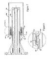
- FIG. 1is a schematic illustration of a conventional DACRS type burner
- FIG. 2is a schematic cross-sectional view of a conventional Swozzle type burner
- FIG. 3is a schematic cross-sectional view of a burner embodying the invention.
- FIG. 4is a schematic view of the noted portion of FIG. 3 ;
- FIG. 5is a perspective view of a counter rotating vane pack provided as an embodiment of the invention.
- FIG. 6is a schematic perspective view illustrating a vane pack configuration according to an alternate embodiment of the invention.
- FIG. 7is a schematic cross-sectional view of a burner according to another embodiment of the invention.
- FIG. 8is a schematic view of the noted portion of FIG. 7 .
- DACRS type fuel injector swirlersare known to have very good mixing characteristics and the swozzle burner architecture is known to have good inherent flame stabilization.
- the inventionis a hybrid structure that adopts features of the DACRS and Swozzle burners to provide the high mixing ability of an axial flowing counter rotating vane swirler with the good dynamic stability characteristics of a bluff center body.
- FIG. 3is a cross-section through a burner 110 embodying the invention, said burner substantially corresponding to a conventional Swozzle type burner as shown in FIG. 2 except for the structure of the swirler shown in the detail of FIG. 4 and in the perspective view of FIG. 5 , or alternately FIG. 6 , as described below.
- an atomized liquid fuel nozzlemay be installed in the center of the burner assembly to provide dual fuel capability.
- the liquid fuel assemblyforming no part of this invention, has been omitted from the illustrations for clarity.
- Air 140enters the burner from a high pressure flow (not illustrated in detail) which surrounds the entire assembly except the discharge end, which enters the combustor reaction zone.
- the air for combustionwill enter the premixer via an inlet flow conditioner (not shown).
- an inlet flow conditioner(not shown).
- a bell-mouth shaped transition 148is used between the inlet flow conditioner (not shown) and the swirler 150 .
- the swirler assemblyincludes a hub 152 , a splitter ring or vane 153 and a shroud 154 (omitted from FIGS.
- the splitter ring 153defines a first, radially inner passage 116 (with respect to the axis of the center body) with the hub 152 and a second, radially outer passage 118 with the shroud 154 , the co-axial passages each having air flow turning, i.e., swirler, vanes 156 , 157 which impart swirl to the combustion air passing through the premixer.
- the vanes 156 of the first passage 116are connected respectively to the center body or hub 152 and the splitter ring 153 and the vanes 157 of the second passage 118 are connected respectively to the splitter ring 153 and the outer wall or shroud 154 .
- the vanes of the inner and outer arraysare oriented to direct the air flow in respectively opposite circumferential directions, as best seen in the FIG. 6 embodiment.
- the vanes of the first and second swirler passagesare co-extensive in the axial direction.
- fuelis fed to the vanes 156 , 157 of both the inner and outer vane passages 116 , 118 , with the fuel being supplied from the inner diameter via annular fuel passage 160 .
- each turning vanecontains a gas fuel supply passage 158 , 159 through the core of the air foil.
- the fuel passagesdistribute gas fuel to at least one gas fuel injection hole 161 , 163 (fuel inlet for injecting fuel into air flowing through the swirler vane assembly) defined respectively in the inner and outer arrays of turning vanes.
- fuel inlet(s)may be located on the pressure side, the suction side or both sides of the turning vanes as in the illustrated embodiment. Also, the fuel inlet(s) may be located on the inner, outer, or both sets of turning vanes.
- Other embodimentsprovide, in addition or in the alternative, fuel injection from fuel inlet(s) in the shroud or hub, so that the turning vane(s) do not have to have fuel passages.
- gas fuelenters the swirler assembly through inlet port(s) and annular passage(s) 160 , which feed the turning vane passages 158 , 159 , for flow to the fuel inlet(s) 161 , 163 .
- the gas fuelbegins mixing with combustion air in the swirler assembly 150 , and fuel/air mixing is completed in the annular passage 162 , which is formed by a center body extension 164 and a swirler shroud extension 166 . After exiting the annular passage, the fuel/air mixture enters the combustor reaction zone where combustion takes place.
- the trailing edge of the splitter ring or vane 153is aerodynamically curved, e.g. elliptically configured, as depicted by way of example in the schematic cross-section of FIG. 4 .
- This featureminimizes the wake or aerodynamic separation area behind the ring, an advantageous feature in burners that employ a pre-mixed gas mixture within the burner due to the possibility of a flame stabilizing or holding in the separation zone, which would result in burning of the fuel nozzle itself.
- the swirler assemblyinjects gas fuel through the surface of the aerodynamic turning vanes (air foils) the disturbance to the air flow field is minimized.
- the use of this geometrydoes not create any regions of flow stagnation or separation/recirculation in the premixer after fuel injection into the air stream. Secondary flows are also minimized with this geometry with the result that control of fuel/air mixing and mixture distribution profile is facilitated.
- the flow fieldremains aerodynamically clean from the region of fuel injection to the premixer discharge into the combustor reaction zone. In the reaction zone, the net resultant swirl induced by the dual vane pack causes a central vortex to form with flow recirculation. This stabilizes the flame front in the reaction zone.
- the center body of the burner assemblygenerally corresponds to the structure of the conventional swozzle burner, so that a further discussion is omitted here.
- FIG. 6An alternate embodiment of the dual vane pack configuration is illustrated by way of example in FIG. 6 .
- This configurationis composed of an inner diameter swirler with sufficient vane thickness to provide a gas passage to the hub or splitter ring of the outer diameters for passage.
- This further configurationis designed so that it can be produced in a single piece casting.
- the individual vanes 256 , 257are offset circumferentially by an appropriate angle to allow the ring-strut-ring thermal stress to dissipate through the splitter ring.
- the vanes in each swirler packagemay also incorporate a lean or a non-radial orientation which will further reduce the ring-strut-ring stress.
- the fuel inlet holes 268 , 270 in this assemblycan be produced using a simple drilling operation due to the radial orientation of the holes.
- the fuel injection holes (inlets) 268located on the inner diameter hub 252 may be positioned axially in front of the vanes 256 and splitter ring 253 to allow access for drilling as at 270 . Note that alternating holes are drilled through the inner hub for fuel flow to the inner diameter swirler 216 and through the inner hub 252 (as at 272 ) and inner diameter swirler vanes 256 to the outer diameter hub or splitter ring 253 to define fuel inlet holes 263 for fuel flow to the outer diameter swirler 218 .
- the fuel feed passagesare produced through a plunge EDM process or a ceramic core in the investment casting, both of which are expensive. Additionally, the fuel injection holes 163 of the FIG. 5 embodiment are typically produced through a plunge EDM through the side of the vanes, which is again very costly. Thus, the embodiment depicted in FIG. 6 is designed for rapid low cost manufacturability.
- FIGS. 7 and 8A further alternate embodiment of the invention is depicted in FIGS. 7 and 8 .
- the fuel gas fuelenters the swirler assembly through inlet port(s) and annular passage(s) 360 , which feed a turning vane passage 358 , for flow to the hollow interior 359 of the splitter ring 353 and to fuel inlet holes 363 defined in the splitter ring and oriented in a radial direction, perpendicular to the centerline.
- the gas fuelbegins mixing with combustion air in the swirler assembly 350 , and fuel/air mixing is completed in the annular passage 362 , which is formed by a center body extension 364 and a swirler shroud extension 366 .
- the fuel/air mixtureAfter exiting the annular passage, the fuel/air mixture enters the combustor reaction zone where combustion takes place.
- the trailing edge of the splitter ring or vane 353is aerodynamically curved, e.g. elliptically configured, to minimize the wake or aerodynamic separation area behind the ring 353 .
- Another alternate embodimentcan incorporate more than two swirlers at different swirl angles, for instance, three coaxial swirlers with the inner and outer swirler co-rotating and the middle swirler counter-rotating.
- one or more of the swirlerscould be flowing predominantly in a radial rather than axial direction, or in a combined radial and axial direction.
Landscapes
- Engineering & Computer Science (AREA)
- Chemical & Material Sciences (AREA)
- Combustion & Propulsion (AREA)
- Mechanical Engineering (AREA)
- General Engineering & Computer Science (AREA)
Abstract
Description
The present invention relates to heavy duty industrial gas turbines and, in particular, to a burner for a gas turbine including a fuel/air premixer and structure for stabilizing pre-mixed burning gas in a gas turbine engine combustor.
Gas turbine manufacturers are regularly involved in research and engineering programs to produce new gas turbines that will operate at high efficiency without producing undesirable air polluting emissions. The primary air polluting emissions usually produced by gas turbines burning conventional hydrocarbon fuels are oxides of nitrogen, carbon monoxide, and unburned hydrocarbons. It is well known in the art that oxidation of molecular nitrogen in air breathing engines is highly dependent upon the maximum hot gas temperature in the combustion system reaction zone. The rate of chemical reactions forming oxides of nitrogen (NOx) is an exponential function of temperature. If the temperature of the combustion chamber hot gas is controlled to a sufficiently low level, thermal NOx will not be produced.
One preferred method of controlling the temperature of the reaction zone of a combustor below the level at which thermal NOx is formed is to premix fuel and air to a lean mixture prior to combustion. The thermal mass of the excess air present in the reaction zone of a lean premixed combustor absorbs heat and reduces the temperature rise of the products of combustion to a level where thermal NOx is not formed.
There are several problems associated with dry low emissions combustors operating with lean premixing of fuel and air in which flammable mixtures of fuel and air exist within the premixing section of the combustor, which is external to the reaction zone of the combustor. There is a tendency for combustion to occur within the premixing section due to flashback, which occurs when flame propagates from the combustor reaction zone into the premixing section, or autoignition, which occurs when the dwell time and temperature for the fuel/air mixture in the premixing section are sufficient for combustion to be initiated without an igniter. The consequences of combustion in the premixing section are degradation of emissions performance and/or overheating and damage to the premixing section, which is typically not designed to withstand the heat of combustion. Therefore, a problem to be solved is to prevent flashback or autoignition resulting in combustion within the premixer.
In addition, the mixture of fuel and air exiting the premixer and entering the reaction zone of the combustor must be very uniform to achieve the desired emissions performance. If regions in the flow field exist where fuel/air mixture strength is significantly richer than average, the products of combustion in these regions will reach a higher temperature than average, and thermal NOx will be formed. This can result in failure to meet NOx emissions objectives depending upon the combination of temperature and residence time. If regions in the flow field exist where the fuel/air mixture strength is significantly leaner than average, then quenching may occur with failure to oxidize hydrocarbons and/or carbon monoxide to equilibrium levels. This can result in failure to meet carbon monoxide (CO) and/or unburned hydrocarbon (UHC) emissions objectives. Thus, another problem to be solved is to produce a fuel/air mixture strength distribution, exiting the premixer, which is sufficiently uniform to meet emissions performance objectives.
Still further, in order to meet the emissions performance objectives imposed upon the gas turbine in many applications, it is necessary to reduce the fuel/air mixture strength to a level that is close to the lean flammability limit for most hydrocarbon fuels. This results in a reduction in flame propagation speed as well as emissions. As a consequence, lean premixing combustors tend to be less stable than more conventional diffusion flame combustors, and high level combustion driven dynamic pressure fluctuation (dynamics) often results. Dynamics can have adverse consequences such as combustor and turbine hardware damage due to wear or fatigue, flashback or blow out. Thus, yet another problem to be solved is to control the combustion dynamics to an acceptably low level.
Lean, premixing fuel injectors for emissions abatement are in common use throughout the industry, having been reduced to practice in heavy duty industrial gas turbines for more than two decades. A representative example of such a device is described in U.S. Pat. No. 5,259,184, the disclosure of which is incorporated herein by this reference. Such devices have achieved great progress in the area of gas turbine exhaust emissions abatement. Reduction of oxides of nitrogen, NOx, emissions by an order of magnitude or more relative to the diffusion flame burners of the prior art have been achieved without the use of diluent injection such as steam or water.
As noted above, however, these gains in emissions performance have been made at the risk of incurring several problems. In particular, flashback and flame holding within the premixing section of the device result in degradation of emissions performance and/or hardware damage due to overheating. In addition, increased levels of combustion driven dynamic pressure activity results in a reduction in the useful life of combustion system parts and/or other parts of the gas turbine due to wear or high cycle fatigue failures. Still further, gas turbine operational complexity is increased and/or operating restrictions on the gas turbine are necessary in order to avoid conditions leading to high-level dynamic pressure activity, flashback, or blow out.
In addition to these problems, conventional lean premixed combustors have not achieved maximum emission reductions possible with perfectly uniform premixing of fuel and air.
Dual Annular Counter Rotating Swirler (DACRS) type fuel injector swirlers, representative examples of which are described in U.S. Pat. Nos. 5,165,241, 5,251,447, 5,351,477, 5,590,529, 5,638,682, 5,680,766, the disclosures of which are incorporated herein by this reference, are known to have very good mixing characteristics due to their high fluid shear and turbulence. Referring to the schematic representation inFIG. 1 , aDACRS type burner 10 is composed of a convergingcenter body 12 and a counter rotatingvane pack 14 defining a radiallyinner passage 16 and a radiallyouter passage 18 with respect to theaxis 20 of the center body, co-axial passages each having swirler vanes. The nozzle structure is supported by an outerdiameter support stem 22 containing afuel manifold 24 for feeding fuel to the vanes of theouter passage 18.
While DACRS type fuel injector swirlers are known to have very good mixing characteristics, these swirlers do not produce a strong recirculating flow at the centerline and hence frequently require additional injection of non-premixed fuel to fully stabilize the flame. This non-premixed fuel increases the NOx emissions above the level that could be attained were the fuel and air fully premixed.
Swozzle type burners, a representative example of which is described in U.S. Pat. No. 6,438,961, the disclosure of which is incorporated herein by this reference, employ a cylindrical center body which extends down the center line of the burner. The end of this center body provides a bluff body, forming in its wake a strong recirculation zone to which the flame anchors. This type of burner architecture is known to have good inherent flame stabilization.
Referring toFIG. 2 , an example of a swozzle type burner is schematically depicted. Air enters theburner 42 at40, from a high pressure plenum, which surrounds the assembly, except thedischarge end 44 which enters the combustor reaction zone.
After passing through theinlet 40, the air enters the swirler or ‘swozzle’assembly 50. The swozzle assembly includes a hub52 (e.g., the center body) and ashroud 54 connected by a series of air foil shapedturning vanes 56 which impart swirl to the combustion air passing through the premixer. Eachturning vane 56 includes gas fuel supply passage(s)58 through the core of the air foil. These fuel passages distribute gas fuel to gas fuel injection holes (not shown) which penetrate the wall of the air foil. Gas fuel enters the swozzle assembly through inlet port(s) and annular passage(s)60, which feed theturning vane passages 58. The gas fuel begins mixing with combustion air in theswozzle assembly 62, and fuel/air mixing is completed in the annular passage, which is formed by acenter body extension 64 and aswozzle shroud extension 66. After exiting the annular passage, the fuel/air mixture enters the combustor reaction zone where combustion takes place.
The DACRS and swozzle type burners are both well-established burner technologies. That is not to say, however, that these burners cannot be improved upon. Indeed, as noted above, the DACRS type burners do not typically provide good premixed flame stabilization. Swozzle type burners, on the other hand, do not typically achieve fully uniform premixing of fuel and air.
The invention provides a unique combination of burner concepts to include a dual, counter rotating, axial flowing swirler so as to exhibit very good mixing characteristics, with a cylindrical bluff center body to provide good flame stabilization.
Thus, the invention may be embodied in a burner for use in a combustion system of an industrial gas turbine, the burner comprising: an outer peripheral wall; a burner center body coaxially disposed within said outer wall; a fuel/air premixer including an air inlet, at least one fuel inlet, and a splitter ring, the splitter ring defining a first, radially inner passage, with respect to the axis of the center body, with the center body and a second, radially outer passage with the outer wall, the first and second passages each having air flow turning vanes which impart swirl to the combustion air passing through the premixer, said vanes connected respectively to said center body and said splitter ring and to said splitter ring and said outer wall; and a gas fuel flow passage defined within said center body and extending at least part circumferentially thereof, for conducting gas fuel to said fuel/air premixer.
The invention may also be embodied in a burner for use in a combustion system of an industrial gas turbine, the burner comprising: an outer peripheral wall; a burner center body coaxially disposed within said outer wall; a fuel/air premixer including an air inlet, at least one fuel inlet, and a splitter ring, the splitter ring defining a first, radially inner passage, with respect to the axis of the center body, with the center body and a second, radially outer passage with the outer wall, the first and second passages each having air flow turning vanes which impart swirl to the combustion air passing through the premixer, said vanes connected respectively to said center body and said splitter ring and to said splitter ring and said outer wall; an annular mixing passage defined between said outer wall and said center body, downstream of the turning vanes, said outer wall extending generally in parallel to said center body and in parallel to said axis of said center body, so that said mixing passage has a substantially constant inner and outer diameter along the length of the center body.
The invention may further be embodied in a method of premixing fuel and air in a burner for a combustion system of a gas turbine, the burner including an outer peripheral wall; a burner center body coaxially disposed within said outer wall; a fuel/air premixer including an air inlet, at least one fuel inlet, and a splitter ring, the splitter ring defining a first, radially inner passage, with respect to the axis of the center body, with the center body and a second, radially outer passage with the outer wall, the first and second passages each having air flow turning vanes which impart swirl to the combustion air passing through the premixer, said vanes connected respectively to said center body and said splitter ring and to said splitter ring and said outer wall, at least some of said vanes comprising an internal fuel flow passage, the fuel inlet introducing fuel into said internal fuel flow passages; and a gas fuel flow passage defined within said center body and extending at least part circumferentially thereof, for conducting gas fuel to said fuel/air premixer; the method comprising: (a) controlling a radial and circumferential distribution of incoming air upstream of the fuel inlet; (b) flowing said incoming air into said first and second passages of said swirler assembly; (b) imparting swirl to the incoming air with said turning vanes; and (c) mixing fuel and air into a uniform mixture downstream of said turning vanes, for injection into a combustor reaction zone of the burner.
These and other objects and advantages of this invention, will be more completely understood and appreciated by careful study of the following more detailed description of the presently preferred exemplary embodiments of the invention taken in conjunction with the accompanying drawings, in which:
As mentioned above, DACRS type fuel injector swirlers are known to have very good mixing characteristics and the swozzle burner architecture is known to have good inherent flame stabilization. The invention is a hybrid structure that adopts features of the DACRS and Swozzle burners to provide the high mixing ability of an axial flowing counter rotating vane swirler with the good dynamic stability characteristics of a bluff center body.
In an embodiment of the invention, as depicted for example inFIGS. 3 ,4 and5, fuel is fed to thevanes outer vane passages annular fuel passage 160. This is a particularly desirable configuration because the inner diameter support andfuel feed passage 160 are features known from the Swozzle type burner and are standard configuration for mounting burners to an end cover which is required for a can type combustor. Thus, at least some and typically each turning vane contains a gasfuel supply passage fuel injection hole 161,163 (fuel inlet for injecting fuel into air flowing through the swirler vane assembly) defined respectively in the inner and outer arrays of turning vanes. These fuel inlet(s) may be located on the pressure side, the suction side or both sides of the turning vanes as in the illustrated embodiment. Also, the fuel inlet(s) may be located on the inner, outer, or both sets of turning vanes. Other embodiments provide, in addition or in the alternative, fuel injection from fuel inlet(s) in the shroud or hub, so that the turning vane(s) do not have to have fuel passages.
In the embodiment illustrated inFIGS. 3–5 , gas fuel enters the swirler assembly through inlet port(s) and annular passage(s)160, which feed the turningvane passages swirler assembly 150, and fuel/air mixing is completed in theannular passage 162, which is formed by acenter body extension 164 and aswirler shroud extension 166. After exiting the annular passage, the fuel/air mixture enters the combustor reaction zone where combustion takes place.
According to a further feature of the invention, the trailing edge of the splitter ring orvane 153 is aerodynamically curved, e.g. elliptically configured, as depicted by way of example in the schematic cross-section ofFIG. 4 . This feature minimizes the wake or aerodynamic separation area behind the ring, an advantageous feature in burners that employ a pre-mixed gas mixture within the burner due to the possibility of a flame stabilizing or holding in the separation zone, which would result in burning of the fuel nozzle itself.
Since the swirler assembly injects gas fuel through the surface of the aerodynamic turning vanes (air foils) the disturbance to the air flow field is minimized. The use of this geometry does not create any regions of flow stagnation or separation/recirculation in the premixer after fuel injection into the air stream. Secondary flows are also minimized with this geometry with the result that control of fuel/air mixing and mixture distribution profile is facilitated. The flow field remains aerodynamically clean from the region of fuel injection to the premixer discharge into the combustor reaction zone. In the reaction zone, the net resultant swirl induced by the dual vane pack causes a central vortex to form with flow recirculation. This stabilizes the flame front in the reaction zone. As long as the velocity in the premixer remains above the turbulent flame propagation speed, flame will not propagate into the premixer (flash back) and with no flow separation or recirculation in the premixer, flame will not anchor in the premixer in the event of a transient causing flow reversal. The ability of the dual vane pack structure to resist flash back and flame holding is important since occurrence of these phenomena causes the premixer to over heat with subsequent damage potential.
The center body of the burner assembly generally corresponds to the structure of the conventional swozzle burner, so that a further discussion is omitted here.
An alternate embodiment of the dual vane pack configuration is illustrated by way of example inFIG. 6 . This configuration is composed of an inner diameter swirler with sufficient vane thickness to provide a gas passage to the hub or splitter ring of the outer diameters for passage. This further configuration is designed so that it can be produced in a single piece casting. Theindividual vanes inner diameter hub 252 may be positioned axially in front of thevanes 256 andsplitter ring 253 to allow access for drilling as at270. Note that alternating holes are drilled through the inner hub for fuel flow to theinner diameter swirler 216 and through the inner hub252 (as at272) and innerdiameter swirler vanes 256 to the outer diameter hub orsplitter ring 253 to define fuel inlet holes263 for fuel flow to theouter diameter swirler 218. In a typical Swozzle design, the fuel feed passages are produced through a plunge EDM process or a ceramic core in the investment casting, both of which are expensive. Additionally, the fuel injection holes163 of theFIG. 5 embodiment are typically produced through a plunge EDM through the side of the vanes, which is again very costly. Thus, the embodiment depicted inFIG. 6 is designed for rapid low cost manufacturability.
A further alternate embodiment of the invention is depicted inFIGS. 7 and 8 . In this embodiment the fuel gas fuel enters the swirler assembly through inlet port(s) and annular passage(s)360, which feed a turningvane passage 358, for flow to thehollow interior 359 of thesplitter ring 353 and to fuel inlet holes363 defined in the splitter ring and oriented in a radial direction, perpendicular to the centerline. As in the embodiments described above, the gas fuel begins mixing with combustion air in theswirler assembly 350, and fuel/air mixing is completed in theannular passage 362, which is formed by acenter body extension 364 and aswirler shroud extension 366. After exiting the annular passage, the fuel/air mixture enters the combustor reaction zone where combustion takes place. In this embodiment, as in the embodiment ofFIG. 4 , the trailing edge of the splitter ring orvane 353 is aerodynamically curved, e.g. elliptically configured, to minimize the wake or aerodynamic separation area behind thering 353.
While the invention has been described in connection with what is presently considered to be the most practical and preferred embodiment, it is to be understood that the invention is not to be limited to the disclosed embodiment, but on the contrary, is intended to cover various modifications and equivalent arrangements included within the spirit and scope of the appended claims. Thus, other embodiments are possible that preserve the intent of the invention while differing in subtle ways. One such embodiment achieves high shear between the two swirling streams, and hence strong turbulent mixing, using two swirlers rotating in the same direction relative to the centerbody axis, but at substantially different swirl angles. For instance, an inner swirler with a swirl angle of 20 degrees and outer swirler with swirl angle of 60 degrees may accomplish similar mixing to the preferred embodiment, but result in a higher residual swirl and hence stronger recirculation and flame stabilization in the flame zone. Another alternate embodiment can incorporate more than two swirlers at different swirl angles, for instance, three coaxial swirlers with the inner and outer swirler co-rotating and the middle swirler counter-rotating. In a third possible alternate embodiment, one or more of the swirlers could be flowing predominantly in a radial rather than axial direction, or in a combined radial and axial direction.
Claims (22)
1. A burner for use in a combustion system of an industrial gas turbine, the burner comprising:
an outer peripheral wall;
a burner center body coaxially disposed within said outer wall;
a fuel/air premixer including an air inlet, at least one fuel inlet, and a splitter ring, the splitter ring defining a first, radially inner passage, with respect to the axis of the center body, with the center body and a second, radially outer passage with the outer wall, the first and second passages each having air flow turning vanes which impart swirl to the combustion air passing through the premixer, said vanes connected respectively to said center body and said splitter ring and to said splitter ring and said outer wall; and
a gas fuel flow passage defined within said center body and extending at least part circumferentially thereof, for conducting gas fuel to said fuel/air premixer.
2. A burner according toclaim 1 , wherein at least some vanes of said radially inner passage comprise an internal fuel flow passage, the gas fuel flow passage introducing fuel into said internal fuel flow passages.
3. A burner according toclaim 2 , wherein said at least one fuel inlet comprises a plurality of fuel metering holes communicating with the internal fuel flow passages.
4. A burner according toclaim 2 , wherein there are a plurality of fuel inlets, at least some of which are defined in said vanes having fuel flow passages.
5. A burner according toclaim 2 , wherein said splitter ring defines a hollow interior fuel cavity and wherein said at least fuel inlet is defined in said splitter ring, in communication with said hollow cavity.
6. A burner according toclaim 1 , wherein the trailing edge of the splitter ring is aerodynamically curved to minimize a wake or aerodynamic separation area behind the ring.
7. A burner according toclaim 1 , further comprising an annular mixing passage downstream of the turning vanes, defined between said outer wall and said center body.
8. A burner according toclaim 1 , wherein said outer wall extends generally in parallel to said center body.
9. A burner according toclaim 7 , wherein said outer wall extends generally in parallel to said center body and in parallel to said axis of said center body, so that said mixing passage has a substantially constant inner and outer diameter along the length of the center body.
10. A burner according toclaim 1 , wherein a downstream end of said center body provides a bluff body to which the flame anchors.
11. A burner according toclaim 1 , wherein the outer passage swirl direction is counter-rotating relative to the inner passage swirl direction.
12. A burner for use in a combustion system of an industrial gas turbine, the burner comprising:
an outer peripheral wall;
a burner center body coaxially disposed within said outer wall;
a fuel/air premixer including an air inlet, at least one fuel inlet, and a splitter ring, the splitter ring defining a first, radially inner passage, with respect to the axis of the center body, with the center body and a second, radially outer passage with the outer wall, the first and second passages each having air flow turning vanes which impart swirl to the combustion air passing through the premixer, said vanes connected respectively to said center body and said splitter ring and to said splitter ring and said outer wall;
an annular mixing passage defined between said outer wall and said center body, downstream of the turning vanes, said outer wall extending generally in parallel to said center body and in parallel to said axis of said center body, so that said mixing passage has a substantially constant inner and outer diameter along the length of the center body.
13. A burner according toclaim 12 , wherein a downstream end of said center body provides a bluff body to which the flame anchors.
14. A burner according toclaim 12 , wherein at least some vanes of said radially inner passage comprise an internal fuel flow passage, the fuel inlet introducing fuel into said internal fuel flow passages.
15. A burner according toclaim 14 , wherein said at least one fuel inlet comprises a plurality of fuel metering holes communicating with the internal fuel flow passages.
16. A burner according toclaim 14 , wherein there are a plurality of fuel inlets, at least some of which are defined in said vanes having fuel flow passages.
17. A burner according toclaim 12 , wherein said splitter ring defines a hollow interior fuel cavity and wherein said at least fuel inlet is defined in said splitter ring, in communication with said hollow cavity.
18. A burner according toclaim 12 , wherein the trailing edge of the splitter ring is aerodynamically curved to minimize a wake or aerodynamic separation area behind the ring.
19. A burner according toclaim 12 , wherein the outer passage swirl direction is counter-rotating relative to the inner passage swirl direction.
20. A method of premixing fuel and air in a burner for a combustion system of a gas turbine, the burner including an outer peripheral wall; a burner center body coaxially disposed within said outer wall; a fuel/air premixer including an air inlet, at least one fuel inlet, and a splitter ring, the splitter ring defining a first, radially inner passage, with respect to the axis of the center body, with the center body and a second, radially outer passage with the outer wall, the first and second passages each having air flow turning vanes which impart swirl to the combustion air passing through the premixer, said vanes connected respectively to said center body and said splitter ring and to said splitter ring and said outer wall, at least some of said vanes comprising an internal fuel flow passage, the fuel inlet introducing fuel into said internal fuel flow passages; and a gas fuel flow passage defined within said center body and extending at least part circumferentially thereof, for conducting gas fuel to said fuel/air premixer; the method comprising:
(a) controlling a radial and circumferential distribution of incoming air upstream of the fuel inlet;
(b) flowing said incoming air into said first and second passages of said swirler assembly;
(b) imparting swirl to the incoming air with said turning vanes; and
(c) mixing fuel and air into a uniform mixture downstream of said turning vanes, for injection into a combustor reaction zone of the burner.
21. A method according toclaim 20 , wherein the outer passage swirl direction is counter-rotating relative to the inner passage swirl direction.
22. A burner according toclaim 12 , wherein said at least one fuel inlet comprises a plurality of fuel metering holes for directing fuel in a direction substantially perpendicular to an air flow direction through the premixer.
Priority Applications (4)
| Application Number | Priority Date | Filing Date | Title |
|---|---|---|---|
| US10/862,427US6993916B2 (en) | 2004-06-08 | 2004-06-08 | Burner tube and method for mixing air and gas in a gas turbine engine |
| DE102005024062ADE102005024062B4 (en) | 2004-06-08 | 2005-05-25 | Burner tube and method of mixing air and gas in a gas turbine engine |
| JP2005166576AJP2005351616A (en) | 2004-06-08 | 2005-06-07 | Burner tube and method for mixing air and gas in gas turbine engine |
| CNB2005100785224ACN100554785C (en) | 2004-06-08 | 2005-06-08 | Be used for combustion tube and method that the air of gas turbine is mixed |
Applications Claiming Priority (1)
| Application Number | Priority Date | Filing Date | Title |
|---|---|---|---|
| US10/862,427US6993916B2 (en) | 2004-06-08 | 2004-06-08 | Burner tube and method for mixing air and gas in a gas turbine engine |
Publications (2)
| Publication Number | Publication Date |
|---|---|
| US20050268618A1 US20050268618A1 (en) | 2005-12-08 |
| US6993916B2true US6993916B2 (en) | 2006-02-07 |
Family
ID=35446172
Family Applications (1)
| Application Number | Title | Priority Date | Filing Date |
|---|---|---|---|
| US10/862,427Expired - Fee RelatedUS6993916B2 (en) | 2004-06-08 | 2004-06-08 | Burner tube and method for mixing air and gas in a gas turbine engine |
Country Status (4)
| Country | Link |
|---|---|
| US (1) | US6993916B2 (en) |
| JP (1) | JP2005351616A (en) |
| CN (1) | CN100554785C (en) |
| DE (1) | DE102005024062B4 (en) |
Cited By (148)
| Publication number | Priority date | Publication date | Assignee | Title |
|---|---|---|---|---|
| US20060236700A1 (en)* | 2005-04-22 | 2006-10-26 | Mitsubishi Heavy Industries, Ltd. | Combustor of gas turbine |
| US20070227156A1 (en)* | 2006-03-30 | 2007-10-04 | Mitsubishi Heavy Industries, Ltd. | Combustor of gas turbine and combustion control method for gas turbine |
| US20070277531A1 (en)* | 2006-06-05 | 2007-12-06 | General Electric Company | Secondary Fuel Injection From Stage One Nozzle |
| US20070277530A1 (en)* | 2006-05-31 | 2007-12-06 | Constantin Alexandru Dinu | Inlet flow conditioner for gas turbine engine fuel nozzle |
| CN101153558A (en)* | 2006-09-29 | 2008-04-02 | 通用电气公司 | Premixing device, gas turbines comprising the premixing device, and methods of use |
| US20080078183A1 (en)* | 2006-10-03 | 2008-04-03 | General Electric Company | Liquid fuel enhancement for natural gas swirl stabilized nozzle and method |
| US20080104961A1 (en)* | 2006-11-08 | 2008-05-08 | Ronald Scott Bunker | Method and apparatus for enhanced mixing in premixing devices |
| US20080148736A1 (en)* | 2005-06-06 | 2008-06-26 | Mitsubishi Heavy Industries, Ltd. | Premixed Combustion Burner of Gas Turbine Technical Field |
| US20080276622A1 (en)* | 2007-05-07 | 2008-11-13 | Thomas Edward Johnson | Fuel nozzle and method of fabricating the same |
| US20080289341A1 (en)* | 2005-06-06 | 2008-11-27 | Mitsubishi Heavy Industries, Ltd. | Combustor of Gas Turbine |
| US20090056336A1 (en)* | 2007-08-28 | 2009-03-05 | General Electric Company | Gas turbine premixer with radially staged flow passages and method for mixing air and gas in a gas turbine |
| US20090111063A1 (en)* | 2007-10-29 | 2009-04-30 | General Electric Company | Lean premixed, radial inflow, multi-annular staged nozzle, can-annular, dual-fuel combustor |
| US20090173074A1 (en)* | 2008-01-03 | 2009-07-09 | General Electric Company | Integrated fuel nozzle ifc |
| DE102008014744A1 (en)* | 2008-03-18 | 2009-09-24 | Rolls-Royce Deutschland Ltd & Co Kg | Gas turbine burner for a gas turbine with a rinsing mechanism for a fuel nozzle |
| US20090249789A1 (en)* | 2008-04-08 | 2009-10-08 | Baifang Zuo | Burner tube premixer and method for mixing air and gas in a gas turbine engine |
| US20090255265A1 (en)* | 2008-04-11 | 2009-10-15 | General Electric Company | Swirlers |
| US20090266077A1 (en)* | 2008-04-23 | 2009-10-29 | Khawar Syed | Mixing chamber |
| US20100008179A1 (en)* | 2008-07-09 | 2010-01-14 | General Electric Company | Pre-mixing apparatus for a turbine engine |
| US20100011770A1 (en)* | 2008-07-21 | 2010-01-21 | Ronald James Chila | Gas Turbine Premixer with Cratered Fuel Injection Sites |
| US20100031662A1 (en)* | 2008-08-05 | 2010-02-11 | General Electric Company | Turbomachine injection nozzle including a coolant delivery system |
| US20100078506A1 (en)* | 2008-09-30 | 2010-04-01 | General Electric Company | Circumferential fuel circuit divider |
| US20100095675A1 (en)* | 2008-10-17 | 2010-04-22 | General Electric Company | Combustor Burner Vanelets |
| US20100101229A1 (en)* | 2008-10-23 | 2010-04-29 | General Electric Company | Flame Holding Tolerant Fuel and Air Premixer for a Gas Turbine Combustor |
| US7707833B1 (en)* | 2009-02-04 | 2010-05-04 | Gas Turbine Efficiency Sweden Ab | Combustor nozzle |
| US20100107643A1 (en)* | 2008-10-31 | 2010-05-06 | Korea Electric Power Corporation | Triple swirl gas turbine combustor |
| US20100115953A1 (en)* | 2008-11-12 | 2010-05-13 | Davis Jr Lewis Berkley | Integrated Combustor and Stage 1 Nozzle in a Gas Turbine and Method |
| US20100132364A1 (en)* | 2008-12-01 | 2010-06-03 | Myers Geoffrey D | Fuel nozzle detachable burner tube |
| US20100170253A1 (en)* | 2009-01-07 | 2010-07-08 | General Electric Company | Method and apparatus for fuel injection in a turbine engine |
| US20100180600A1 (en)* | 2009-01-22 | 2010-07-22 | General Electric Company | Nozzle for a turbomachine |
| US20100190119A1 (en)* | 2006-03-01 | 2010-07-29 | Honeywell International Inc. | Industrial burner |
| US20100186413A1 (en)* | 2009-01-23 | 2010-07-29 | General Electric Company | Bundled multi-tube nozzle for a turbomachine |
| US20100186412A1 (en)* | 2009-01-27 | 2010-07-29 | General Electric Company | Annular fuel and air co-flow premixer |
| US20100192581A1 (en)* | 2009-02-04 | 2010-08-05 | General Electricity Company | Premixed direct injection nozzle |
| US20100199675A1 (en)* | 2009-02-12 | 2010-08-12 | General Electric Company | Fuel injection for gas turbine combustors |
| US20100212322A1 (en)* | 2009-02-20 | 2010-08-26 | General Electric Company | Coaxial fuel and air premixer for a gas turbine combustor |
| US20100236252A1 (en)* | 2009-03-23 | 2010-09-23 | Michael Huth | Swirl generator, method for preventing flashback in a burner having at least one swirl generator and burner |
| US20100242482A1 (en)* | 2009-03-30 | 2010-09-30 | General Electric Company | Method and system for reducing the level of emissions generated by a system |
| US20100263383A1 (en)* | 2009-04-16 | 2010-10-21 | General Electric Company | Gas turbine premixer with internal cooling |
| US20100269508A1 (en)* | 2007-11-29 | 2010-10-28 | Mitsubishi Heavy Industries, Ltd. | Combustion burner |
| US20100269507A1 (en)* | 2009-04-23 | 2010-10-28 | Abdul Rafey Khan | Radial lean direct injection burner |
| US20100287947A1 (en)* | 2005-09-30 | 2010-11-18 | Solar Turbines Incorporated | Acoustically Tuned Combustion for a Gas Turbine Engine |
| CN101892909A (en)* | 2009-05-21 | 2010-11-24 | 通用电气公司 | Turbine fuel nozzle with premixed device of band auxiliary vane |
| US20100316965A1 (en)* | 2007-12-19 | 2010-12-16 | Joseph Le Mer | Device and method for stabilizing the pressure and the flow of a gaseous mixture supplied to a surface-combustion cylindrical burner |
| US20110000671A1 (en)* | 2008-03-28 | 2011-01-06 | Frank Hershkowitz | Low Emission Power Generation and Hydrocarbon Recovery Systems and Methods |
| US20110072824A1 (en)* | 2009-09-30 | 2011-03-31 | General Electric Company | Appartus and method for a gas turbine nozzle |
| US20110107765A1 (en)* | 2009-11-09 | 2011-05-12 | General Electric Company | Counter rotated gas turbine fuel nozzles |
| US8024932B1 (en) | 2010-04-07 | 2011-09-27 | General Electric Company | System and method for a combustor nozzle |
| US20110289928A1 (en)* | 2010-05-25 | 2011-12-01 | Fox Timothy A | Air/fuel supply system for use in a gas turbine engine |
| US8104286B2 (en) | 2009-01-07 | 2012-01-31 | General Electric Company | Methods and systems to enhance flame holding in a gas turbine engine |
| US20120131923A1 (en)* | 2010-11-30 | 2012-05-31 | General Electric Company | System and method for premixer wake and vortex filling for enhanced flame-holding resistance |
| US20120175430A1 (en)* | 2011-01-06 | 2012-07-12 | General Electric Company | System and method for enhancing flow in a nozzle |
| US20120186259A1 (en)* | 2011-01-26 | 2012-07-26 | United Technologies Corporation | Fuel injector assembly |
| US8307660B2 (en)* | 2011-04-11 | 2012-11-13 | General Electric Company | Combustor nozzle and method for supplying fuel to a combustor |
| US20130040254A1 (en)* | 2011-08-08 | 2013-02-14 | General Electric Company | System and method for monitoring a combustor |
| US8453454B2 (en) | 2010-04-14 | 2013-06-04 | General Electric Company | Coannular oil injection nozzle |
| US20130205799A1 (en)* | 2012-02-15 | 2013-08-15 | Donald Mark Bailey | Outer Fuel Nozzle Inlet Flow Conditioner Interface to End Cap |
| US8528839B2 (en)* | 2011-01-19 | 2013-09-10 | General Electric Company | Combustor nozzle and method for fabricating the combustor nozzle |
| US8646275B2 (en) | 2007-09-13 | 2014-02-11 | Rolls-Royce Deutschland Ltd & Co Kg | Gas-turbine lean combustor with fuel nozzle with controlled fuel inhomogeneity |
| US8863525B2 (en) | 2011-01-03 | 2014-10-21 | General Electric Company | Combustor with fuel staggering for flame holding mitigation |
| US20140318150A1 (en)* | 2013-04-25 | 2014-10-30 | Khalid Oumejjoud | Removable swirler assembly for a combustion liner |
| US8893500B2 (en) | 2011-05-18 | 2014-11-25 | Solar Turbines Inc. | Lean direct fuel injector |
| US8919132B2 (en) | 2011-05-18 | 2014-12-30 | Solar Turbines Inc. | Method of operating a gas turbine engine |
| US8950188B2 (en) | 2011-09-09 | 2015-02-10 | General Electric Company | Turning guide for combustion fuel nozzle in gas turbine and method to turn fuel flow entering combustion chamber |
| US8955329B2 (en) | 2011-10-21 | 2015-02-17 | General Electric Company | Diffusion nozzles for low-oxygen fuel nozzle assembly and method |
| US8959921B2 (en) | 2010-07-13 | 2015-02-24 | General Electric Company | Flame tolerant secondary fuel nozzle |
| US8984857B2 (en) | 2008-03-28 | 2015-03-24 | Exxonmobil Upstream Research Company | Low emission power generation and hydrocarbon recovery systems and methods |
| US9027321B2 (en) | 2008-03-28 | 2015-05-12 | Exxonmobil Upstream Research Company | Low emission power generation and hydrocarbon recovery systems and methods |
| US9046262B2 (en) | 2011-06-27 | 2015-06-02 | General Electric Company | Premixer fuel nozzle for gas turbine engine |
| US9115896B2 (en) | 2012-07-31 | 2015-08-25 | General Electric Company | Fuel-air mixer for use with a combustor assembly |
| US9182124B2 (en) | 2011-12-15 | 2015-11-10 | Solar Turbines Incorporated | Gas turbine and fuel injector for the same |
| US9222671B2 (en) | 2008-10-14 | 2015-12-29 | Exxonmobil Upstream Research Company | Methods and systems for controlling the products of combustion |
| US9267690B2 (en) | 2012-05-29 | 2016-02-23 | General Electric Company | Turbomachine combustor nozzle including a monolithic nozzle component and method of forming the same |
| US9322559B2 (en) | 2013-04-17 | 2016-04-26 | General Electric Company | Fuel nozzle having swirler vane and fuel injection peg arrangement |
| US9353682B2 (en) | 2012-04-12 | 2016-05-31 | General Electric Company | Methods, systems and apparatus relating to combustion turbine power plants with exhaust gas recirculation |
| US9388985B2 (en) | 2011-07-29 | 2016-07-12 | General Electric Company | Premixing apparatus for gas turbine system |
| US9463417B2 (en) | 2011-03-22 | 2016-10-11 | Exxonmobil Upstream Research Company | Low emission power generation systems and methods incorporating carbon dioxide separation |
| US9512759B2 (en) | 2013-02-06 | 2016-12-06 | General Electric Company | System and method for catalyst heat utilization for gas turbine with exhaust gas recirculation |
| US9534788B2 (en) | 2014-04-03 | 2017-01-03 | General Electric Company | Air fuel premixer for low emissions gas turbine combustor |
| US9574496B2 (en) | 2012-12-28 | 2017-02-21 | General Electric Company | System and method for a turbine combustor |
| US9581081B2 (en) | 2013-01-13 | 2017-02-28 | General Electric Company | System and method for protecting components in a gas turbine engine with exhaust gas recirculation |
| US9587510B2 (en) | 2013-07-30 | 2017-03-07 | General Electric Company | System and method for a gas turbine engine sensor |
| US9599070B2 (en) | 2012-11-02 | 2017-03-21 | General Electric Company | System and method for oxidant compression in a stoichiometric exhaust gas recirculation gas turbine system |
| US9599021B2 (en) | 2011-03-22 | 2017-03-21 | Exxonmobil Upstream Research Company | Systems and methods for controlling stoichiometric combustion in low emission turbine systems |
| US9611756B2 (en) | 2012-11-02 | 2017-04-04 | General Electric Company | System and method for protecting components in a gas turbine engine with exhaust gas recirculation |
| US9617914B2 (en) | 2013-06-28 | 2017-04-11 | General Electric Company | Systems and methods for monitoring gas turbine systems having exhaust gas recirculation |
| US9618261B2 (en) | 2013-03-08 | 2017-04-11 | Exxonmobil Upstream Research Company | Power generation and LNG production |
| US9631815B2 (en) | 2012-12-28 | 2017-04-25 | General Electric Company | System and method for a turbine combustor |
| US9631542B2 (en) | 2013-06-28 | 2017-04-25 | General Electric Company | System and method for exhausting combustion gases from gas turbine engines |
| US9638111B2 (en) | 2011-09-14 | 2017-05-02 | Anthony R. Martinez | Providing oxidation to a gas turbine engine |
| US9670841B2 (en) | 2011-03-22 | 2017-06-06 | Exxonmobil Upstream Research Company | Methods of varying low emission turbine gas recycle circuits and systems and apparatus related thereto |
| US9689309B2 (en) | 2011-03-22 | 2017-06-27 | Exxonmobil Upstream Research Company | Systems and methods for carbon dioxide capture in low emission combined turbine systems |
| US9708977B2 (en) | 2012-12-28 | 2017-07-18 | General Electric Company | System and method for reheat in gas turbine with exhaust gas recirculation |
| US9732673B2 (en) | 2010-07-02 | 2017-08-15 | Exxonmobil Upstream Research Company | Stoichiometric combustion with exhaust gas recirculation and direct contact cooler |
| US9732675B2 (en) | 2010-07-02 | 2017-08-15 | Exxonmobil Upstream Research Company | Low emission power generation systems and methods |
| US9752458B2 (en) | 2013-12-04 | 2017-09-05 | General Electric Company | System and method for a gas turbine engine |
| US9784185B2 (en) | 2012-04-26 | 2017-10-10 | General Electric Company | System and method for cooling a gas turbine with an exhaust gas provided by the gas turbine |
| US9784182B2 (en) | 2013-03-08 | 2017-10-10 | Exxonmobil Upstream Research Company | Power generation and methane recovery from methane hydrates |
| US9784140B2 (en) | 2013-03-08 | 2017-10-10 | Exxonmobil Upstream Research Company | Processing exhaust for use in enhanced oil recovery |
| US9803865B2 (en) | 2012-12-28 | 2017-10-31 | General Electric Company | System and method for a turbine combustor |
| US9810050B2 (en) | 2011-12-20 | 2017-11-07 | Exxonmobil Upstream Research Company | Enhanced coal-bed methane production |
| US9819292B2 (en) | 2014-12-31 | 2017-11-14 | General Electric Company | Systems and methods to respond to grid overfrequency events for a stoichiometric exhaust recirculation gas turbine |
| US9835089B2 (en) | 2013-06-28 | 2017-12-05 | General Electric Company | System and method for a fuel nozzle |
| US9863267B2 (en) | 2014-01-21 | 2018-01-09 | General Electric Company | System and method of control for a gas turbine engine |
| US9869279B2 (en) | 2012-11-02 | 2018-01-16 | General Electric Company | System and method for a multi-wall turbine combustor |
| US9869247B2 (en) | 2014-12-31 | 2018-01-16 | General Electric Company | Systems and methods of estimating a combustion equivalence ratio in a gas turbine with exhaust gas recirculation |
| US9885290B2 (en) | 2014-06-30 | 2018-02-06 | General Electric Company | Erosion suppression system and method in an exhaust gas recirculation gas turbine system |
| US9903316B2 (en) | 2010-07-02 | 2018-02-27 | Exxonmobil Upstream Research Company | Stoichiometric combustion of enriched air with exhaust gas recirculation |
| US9903588B2 (en) | 2013-07-30 | 2018-02-27 | General Electric Company | System and method for barrier in passage of combustor of gas turbine engine with exhaust gas recirculation |
| US9903271B2 (en) | 2010-07-02 | 2018-02-27 | Exxonmobil Upstream Research Company | Low emission triple-cycle power generation and CO2 separation systems and methods |
| US9915200B2 (en) | 2014-01-21 | 2018-03-13 | General Electric Company | System and method for controlling the combustion process in a gas turbine operating with exhaust gas recirculation |
| US9932874B2 (en) | 2013-02-21 | 2018-04-03 | Exxonmobil Upstream Research Company | Reducing oxygen in a gas turbine exhaust |
| US9938861B2 (en) | 2013-02-21 | 2018-04-10 | Exxonmobil Upstream Research Company | Fuel combusting method |
| US9951658B2 (en) | 2013-07-31 | 2018-04-24 | General Electric Company | System and method for an oxidant heating system |
| US10012386B2 (en) | 2012-08-06 | 2018-07-03 | Siemens Aktiengesellschaft | Local improvement of the mixture of air and fuel in burners comprising swirl generators having blade ends that are crossed in the outer region |
| US10012151B2 (en) | 2013-06-28 | 2018-07-03 | General Electric Company | Systems and methods for controlling exhaust gas flow in exhaust gas recirculation gas turbine systems |
| US10030588B2 (en) | 2013-12-04 | 2018-07-24 | General Electric Company | Gas turbine combustor diagnostic system and method |
| US10047633B2 (en) | 2014-05-16 | 2018-08-14 | General Electric Company | Bearing housing |
| US10060359B2 (en) | 2014-06-30 | 2018-08-28 | General Electric Company | Method and system for combustion control for gas turbine system with exhaust gas recirculation |
| US10079564B2 (en) | 2014-01-27 | 2018-09-18 | General Electric Company | System and method for a stoichiometric exhaust gas recirculation gas turbine system |
| US10094566B2 (en) | 2015-02-04 | 2018-10-09 | General Electric Company | Systems and methods for high volumetric oxidant flow in gas turbine engine with exhaust gas recirculation |
| US10100741B2 (en) | 2012-11-02 | 2018-10-16 | General Electric Company | System and method for diffusion combustion with oxidant-diluent mixing in a stoichiometric exhaust gas recirculation gas turbine system |
| US10107495B2 (en) | 2012-11-02 | 2018-10-23 | General Electric Company | Gas turbine combustor control system for stoichiometric combustion in the presence of a diluent |
| US10145269B2 (en) | 2015-03-04 | 2018-12-04 | General Electric Company | System and method for cooling discharge flow |
| US10190774B2 (en) | 2013-12-23 | 2019-01-29 | General Electric Company | Fuel nozzle with flexible support structures |
| US10208677B2 (en) | 2012-12-31 | 2019-02-19 | General Electric Company | Gas turbine load control system |
| US10215412B2 (en) | 2012-11-02 | 2019-02-26 | General Electric Company | System and method for load control with diffusion combustion in a stoichiometric exhaust gas recirculation gas turbine system |
| US10221762B2 (en) | 2013-02-28 | 2019-03-05 | General Electric Company | System and method for a turbine combustor |
| US10227920B2 (en) | 2014-01-15 | 2019-03-12 | General Electric Company | Gas turbine oxidant separation system |
| US10240791B2 (en) | 2014-09-19 | 2019-03-26 | Mitsubishi Heavy Industries, Ltd. | Combustion burner, combustor, and gas turbine having a swirl vane with opposite directed surfaces |
| US10253690B2 (en) | 2015-02-04 | 2019-04-09 | General Electric Company | Turbine system with exhaust gas recirculation, separation and extraction |
| US10267270B2 (en) | 2015-02-06 | 2019-04-23 | General Electric Company | Systems and methods for carbon black production with a gas turbine engine having exhaust gas recirculation |
| US10273880B2 (en) | 2012-04-26 | 2019-04-30 | General Electric Company | System and method of recirculating exhaust gas for use in a plurality of flow paths in a gas turbine engine |
| US10288293B2 (en) | 2013-11-27 | 2019-05-14 | General Electric Company | Fuel nozzle with fluid lock and purge apparatus |
| US10315150B2 (en) | 2013-03-08 | 2019-06-11 | Exxonmobil Upstream Research Company | Carbon dioxide recovery |
| US10316746B2 (en) | 2015-02-04 | 2019-06-11 | General Electric Company | Turbine system with exhaust gas recirculation, separation and extraction |
| US10352567B2 (en) | 2015-10-09 | 2019-07-16 | General Electric Company | Fuel-air premixer for a gas turbine |
| US10415830B2 (en)* | 2014-09-19 | 2019-09-17 | Mitsubishi Hitachi Power Systems, Ltd. | Combustion burner, combustor, and gas turbine |
| US10415479B2 (en) | 2013-02-25 | 2019-09-17 | General Electric Company | Fuel/air mixing system for fuel nozzle |
| US10451282B2 (en) | 2013-12-23 | 2019-10-22 | General Electric Company | Fuel nozzle structure for air assist injection |
| US10480792B2 (en) | 2015-03-06 | 2019-11-19 | General Electric Company | Fuel staging in a gas turbine engine |
| US10655542B2 (en) | 2014-06-30 | 2020-05-19 | General Electric Company | Method and system for startup of gas turbine system drive trains with exhaust gas recirculation |
| US10767900B2 (en) | 2015-05-14 | 2020-09-08 | Lochinvar, Llc | Burner with flow distribution member |
| US10788212B2 (en) | 2015-01-12 | 2020-09-29 | General Electric Company | System and method for an oxidant passageway in a gas turbine system with exhaust gas recirculation |
| US10982857B2 (en)* | 2018-02-23 | 2021-04-20 | DOOSAN Heavy Industries Construction Co., LTD | Nozzle for combustors, combustor, and gas turbine including the same |
| US11187414B2 (en) | 2020-03-31 | 2021-11-30 | General Electric Company | Fuel nozzle with improved swirler vane structure |
| DE102009003639B4 (en) | 2008-05-20 | 2024-08-14 | General Electric Technology Gmbh | Methods and systems for reducing combustion dynamics |
| US12163664B2 (en)* | 2020-01-08 | 2024-12-10 | General Electric Company | Premixer for a combustor |
| US12313262B2 (en)* | 2022-11-30 | 2025-05-27 | Doosan Enerbility Co., Ltd. | Nozzle assembly, combustor, and gas turbine including same |
Families Citing this family (49)
| Publication number | Priority date | Publication date | Assignee | Title |
|---|---|---|---|---|
| US7126182B2 (en)* | 2004-08-13 | 2006-10-24 | Micron Technology, Inc. | Memory circuitry |
| US7703288B2 (en)* | 2005-09-30 | 2010-04-27 | Solar Turbines Inc. | Fuel nozzle having swirler-integrated radial fuel jet |
| GB2435508B (en)* | 2006-02-22 | 2011-08-03 | Siemens Ag | A swirler for use in a burner of a gas turbine engine |
| US8015814B2 (en)* | 2006-10-24 | 2011-09-13 | Caterpillar Inc. | Turbine engine having folded annular jet combustor |
| US8117845B2 (en)* | 2007-04-27 | 2012-02-21 | General Electric Company | Systems to facilitate reducing flashback/flame holding in combustion systems |
| JP5412283B2 (en)* | 2007-08-10 | 2014-02-12 | 川崎重工業株式会社 | Combustion device |
| US9188341B2 (en)* | 2008-04-11 | 2015-11-17 | General Electric Company | Fuel nozzle |
| EP2312215A1 (en)* | 2008-10-01 | 2011-04-20 | Siemens Aktiengesellschaft | Burner and Method for Operating a Burner |
| US8220270B2 (en)* | 2008-10-31 | 2012-07-17 | General Electric Company | Method and apparatus for affecting a recirculation zone in a cross flow |
| CN101408315B (en)* | 2008-11-27 | 2010-06-02 | 浙江大学 | A Low Noise and High Efficiency Gas Turbine Combustor |
| US9513009B2 (en) | 2009-02-18 | 2016-12-06 | Rolls-Royce Plc | Fuel nozzle having aerodynamically shaped helical turning vanes |
| US8260523B2 (en)* | 2009-05-04 | 2012-09-04 | General Electric Company | Method for detecting gas turbine engine flashback |
| US20100287938A1 (en)* | 2009-05-14 | 2010-11-18 | General Electric Company | Cross flow vane |
| US20100300102A1 (en)* | 2009-05-28 | 2010-12-02 | General Electric Company | Method and apparatus for air and fuel injection in a turbine |
| EP2270398A1 (en)* | 2009-06-30 | 2011-01-05 | Siemens Aktiengesellschaft | Burner, especially for gas turbines |
| DE102009038848A1 (en)* | 2009-08-26 | 2011-03-03 | Siemens Aktiengesellschaft | Burner, in particular for gas turbines |
| CN101709884B (en)* | 2009-11-25 | 2012-07-04 | 北京航空航天大学 | Premixing and pre-evaporating combustion chamber |
| US20120180494A1 (en)* | 2011-01-14 | 2012-07-19 | General Electric Company | Turbine fuel nozzle assembly |
| US8875516B2 (en)* | 2011-02-04 | 2014-11-04 | General Electric Company | Turbine combustor configured for high-frequency dynamics mitigation and related method |
| US20120312890A1 (en)* | 2011-06-10 | 2012-12-13 | General Electric Company | Fuel Nozzle with Swirling Vanes |
| US8850821B2 (en) | 2011-10-07 | 2014-10-07 | General Electric Company | System for fuel injection in a fuel nozzle |
| US20130192243A1 (en)* | 2012-01-31 | 2013-08-01 | Matthew Patrick Boespflug | Fuel nozzle for a gas turbine engine and method of operating the same |
| US20130219899A1 (en)* | 2012-02-27 | 2013-08-29 | General Electric Company | Annular premixed pilot in fuel nozzle |
| JP5486619B2 (en) | 2012-02-28 | 2014-05-07 | 株式会社日立製作所 | Gas turbine combustor and operation method thereof |
| CN102607060A (en)* | 2012-03-13 | 2012-07-25 | 浙江科技学院 | Method for controlling instability of combustion heat sound |
| US8966907B2 (en)* | 2012-04-16 | 2015-03-03 | General Electric Company | Turbine combustor system having aerodynamic feed cap |
| US8925323B2 (en)* | 2012-04-30 | 2015-01-06 | General Electric Company | Fuel/air premixing system for turbine engine |
| WO2013188880A1 (en)* | 2012-06-15 | 2013-12-19 | Cummins Ip, Inc. | Reductant decomposition and mixing system |
| US9879862B2 (en)* | 2013-03-08 | 2018-01-30 | Rolls-Royce North American Technologies, Inc. | Gas turbine engine afterburner |
| US20150276225A1 (en)* | 2014-03-27 | 2015-10-01 | General Electric Company | Combustor wth pre-mixing fuel nozzle assembly |
| CA2963956C (en)* | 2014-10-17 | 2022-10-04 | Nuovo Pignone Srl | Method for reducing nox emission in a gas turbine, air fuel mixer, gas turbine and swirler |
| CN105716113B (en)* | 2016-02-06 | 2019-03-12 | 中国科学院工程热物理研究所 | Bispin premix burner |
| EP3225915B1 (en) | 2016-03-31 | 2019-02-06 | Rolls-Royce plc | Fuel injector and method of manufactering the same |
| US10234142B2 (en)* | 2016-04-15 | 2019-03-19 | Solar Turbines Incorporated | Fuel delivery methods in combustion engine using wide range of gaseous fuels |
| CN106090921B (en)* | 2016-06-22 | 2018-04-17 | 江苏大学 | A kind of burner that can be used for multi fuel blending combustion phenomena research with dual rotary inflow channel |
| RU2633982C1 (en)* | 2016-06-29 | 2017-10-20 | Акционерное общество "ОДК-Авиадвигатель" | Flame tube of gas turbine engine combustion chamber |
| US20180209639A1 (en)* | 2017-01-20 | 2018-07-26 | Marc Mahé | Gas heater conversion system and method |
| US10941938B2 (en)* | 2018-02-22 | 2021-03-09 | Delavan Inc. | Fuel injectors including gas fuel injection |
| US10890329B2 (en)* | 2018-03-01 | 2021-01-12 | General Electric Company | Fuel injector assembly for gas turbine engine |
| US11007542B2 (en)* | 2019-04-08 | 2021-05-18 | Fmc Technologies, Inc. | Cyclone separator and methods of using same |
| KR102111644B1 (en)* | 2019-06-11 | 2020-05-15 | 두산중공업 주식회사 | Combustor and gas turbine with multiple swirlers formed in different shapes |
| CN111520750B (en)* | 2020-03-25 | 2022-05-20 | 西北工业大学 | New type combustion chamber head fuel injection structure |
| KR102363091B1 (en)* | 2020-07-06 | 2022-02-14 | 두산중공업 주식회사 | Nozzle for combustor, combustor, and gas turbine including the same |
| KR102322596B1 (en)* | 2020-07-17 | 2021-11-05 | 두산중공업 주식회사 | Nozzle assembly for combustor and gas turbine combustor including the same |
| US11754288B2 (en)* | 2020-12-09 | 2023-09-12 | General Electric Company | Combustor mixing assembly |
| CN113047944A (en)* | 2021-03-09 | 2021-06-29 | 魏福宽 | Multifunctional cyclone mechanical supercharger |
| CN113124405B (en)* | 2021-05-14 | 2024-04-30 | 福建华夏蓝天科技有限公司 | Automatically adjustable flame stabilizing disc and burner with same |
| CN114278937A (en)* | 2021-12-30 | 2022-04-05 | 乔治洛德方法研究和开发液化空气有限公司 | Burner, burner module comprising same, burner assembly and heating device |
| WO2025042376A1 (en)* | 2023-08-23 | 2025-02-27 | Istanbul Teknik Universitesi | Partially premixed combustion chamber system stabilised by a swirler and a bluff body |
Citations (37)
| Publication number | Priority date | Publication date | Assignee | Title |
|---|---|---|---|---|
| US3808803A (en)* | 1973-03-15 | 1974-05-07 | Us Navy | Anticarbon device for the scroll fuel carburetor |
| US3915387A (en)* | 1973-06-28 | 1975-10-28 | Snecma | Fuel injection devices |
| US3917173A (en)* | 1972-04-21 | 1975-11-04 | Stal Laval Turbin Ab | Atomizing apparatus for finely distributing a liquid in an air stream |
| US3972182A (en)* | 1973-09-10 | 1976-08-03 | General Electric Company | Fuel injection apparatus |
| US5165241A (en) | 1991-02-22 | 1992-11-24 | General Electric Company | Air fuel mixer for gas turbine combustor |
| US5224333A (en)* | 1990-03-13 | 1993-07-06 | Delavan Inc | Simplex airblast fuel injection |
| US5251447A (en) | 1992-10-01 | 1993-10-12 | General Electric Company | Air fuel mixer for gas turbine combustor |
| US5259184A (en) | 1992-03-30 | 1993-11-09 | General Electric Company | Dry low NOx single stage dual mode combustor construction for a gas turbine |
| US5351477A (en) | 1993-12-21 | 1994-10-04 | General Electric Company | Dual fuel mixer for gas turbine combustor |
| US5590529A (en) | 1994-09-26 | 1997-01-07 | General Electric Company | Air fuel mixer for gas turbine combustor |
| US5613363A (en)* | 1994-09-26 | 1997-03-25 | General Electric Company | Air fuel mixer for gas turbine combustor |
| US5638682A (en) | 1994-09-23 | 1997-06-17 | General Electric Company | Air fuel mixer for gas turbine combustor having slots at downstream end of mixing duct |
| US5647538A (en)* | 1993-12-23 | 1997-07-15 | Rolls Royce Plc | Gas turbine engine fuel injection apparatus |
| US5647215A (en)* | 1995-11-07 | 1997-07-15 | Westinghouse Electric Corporation | Gas turbine combustor with turbulence enhanced mixing fuel injectors |
| US5675971A (en)* | 1996-01-02 | 1997-10-14 | General Electric Company | Dual fuel mixer for gas turbine combustor |
| US5680766A (en) | 1996-01-02 | 1997-10-28 | General Electric Company | Dual fuel mixer for gas turbine combustor |
| US5722230A (en) | 1995-08-08 | 1998-03-03 | General Electric Co. | Center burner in a multi-burner combustor |
| US5822992A (en) | 1995-10-19 | 1998-10-20 | General Electric Company | Low emissions combustor premixer |
| US5901548A (en)* | 1996-12-23 | 1999-05-11 | General Electric Company | Air assist fuel atomization in a gas turbine engine |
| US5916142A (en)* | 1996-10-21 | 1999-06-29 | General Electric Company | Self-aligning swirler with ball joint |
| US5943866A (en) | 1994-10-03 | 1999-08-31 | General Electric Company | Dynamically uncoupled low NOx combustor having multiple premixers with axial staging |
| US5983642A (en)* | 1997-10-13 | 1999-11-16 | Siemens Westinghouse Power Corporation | Combustor with two stage primary fuel tube with concentric members and flow regulating |
| US6112870A (en)* | 1997-09-19 | 2000-09-05 | Kubota Corporation | Clutch pressure control apparatus and method for a working vehicle |
| US6141967A (en)* | 1998-01-09 | 2000-11-07 | General Electric Company | Air fuel mixer for gas turbine combustor |
| US6269646B1 (en) | 1998-01-28 | 2001-08-07 | General Electric Company | Combustors with improved dynamics |
| US6363726B1 (en)* | 2000-09-29 | 2002-04-02 | General Electric Company | Mixer having multiple swirlers |
| US6415594B1 (en)* | 2000-05-31 | 2002-07-09 | General Electric Company | Methods and apparatus for reducing gas turbine engine emissions |
| US6427435B1 (en) | 2000-05-20 | 2002-08-06 | General Electric Company | Retainer segment for swirler assembly |
| US6438961B2 (en) | 1998-02-10 | 2002-08-27 | General Electric Company | Swozzle based burner tube premixer including inlet air conditioner for low emissions combustion |
| US6453660B1 (en)* | 2001-01-18 | 2002-09-24 | General Electric Company | Combustor mixer having plasma generating nozzle |
| US6460344B1 (en)* | 1999-05-07 | 2002-10-08 | Parker-Hannifin Corporation | Fuel atomization method for turbine combustion engines having aerodynamic turning vanes |
| US6474569B1 (en)* | 1997-12-18 | 2002-11-05 | Quinetiq Limited | Fuel injector |
| US6546733B2 (en) | 2001-06-28 | 2003-04-15 | General Electric Company | Methods and systems for cooling gas turbine engine combustors |
| US6609377B2 (en) | 2000-09-29 | 2003-08-26 | General Electric Company | Multiple injector combustor |
| US6708498B2 (en) | 1997-12-18 | 2004-03-23 | General Electric Company | Venturiless swirl cup |
| US20040079085A1 (en)* | 2002-02-01 | 2004-04-29 | Mancini Alfred A. | Method and apparatus to decrease combustor emissions |
| US20050039456A1 (en)* | 2003-08-05 | 2005-02-24 | Japan Aerospace Exploration Agency | Fuel/air premixer for gas turbine combustor |
Family Cites Families (4)
| Publication number | Priority date | Publication date | Assignee | Title |
|---|---|---|---|---|
| US5341477A (en)* | 1989-02-24 | 1994-08-23 | Digital Equipment Corporation | Broker for computer network server selection |
| JP2002213746A (en)* | 2001-01-19 | 2002-07-31 | Mitsubishi Heavy Ind Ltd | Burner, premix fuel nozzle of combustor, and an combustor |
| JP2003042453A (en)* | 2001-07-26 | 2003-02-13 | Mitsubishi Heavy Ind Ltd | Premixing nozzle or premixed burner for gas turbine |
| JP2003074855A (en)* | 2001-08-29 | 2003-03-12 | Mitsubishi Heavy Ind Ltd | Dual combustion nozzle and combustion equipment for gas turbine |
- 2004
- 2004-06-08USUS10/862,427patent/US6993916B2/ennot_activeExpired - Fee Related
- 2005
- 2005-05-25DEDE102005024062Apatent/DE102005024062B4/ennot_activeExpired - Fee Related
- 2005-06-07JPJP2005166576Apatent/JP2005351616A/enactivePending
- 2005-06-08CNCNB2005100785224Apatent/CN100554785C/ennot_activeExpired - Fee Related
Patent Citations (38)
| Publication number | Priority date | Publication date | Assignee | Title |
|---|---|---|---|---|
| US3917173A (en)* | 1972-04-21 | 1975-11-04 | Stal Laval Turbin Ab | Atomizing apparatus for finely distributing a liquid in an air stream |
| US3808803A (en)* | 1973-03-15 | 1974-05-07 | Us Navy | Anticarbon device for the scroll fuel carburetor |
| US3915387A (en)* | 1973-06-28 | 1975-10-28 | Snecma | Fuel injection devices |
| US3972182A (en)* | 1973-09-10 | 1976-08-03 | General Electric Company | Fuel injection apparatus |
| US5224333A (en)* | 1990-03-13 | 1993-07-06 | Delavan Inc | Simplex airblast fuel injection |
| US5165241A (en) | 1991-02-22 | 1992-11-24 | General Electric Company | Air fuel mixer for gas turbine combustor |
| US5259184A (en) | 1992-03-30 | 1993-11-09 | General Electric Company | Dry low NOx single stage dual mode combustor construction for a gas turbine |
| US5251447A (en) | 1992-10-01 | 1993-10-12 | General Electric Company | Air fuel mixer for gas turbine combustor |
| US5351477A (en) | 1993-12-21 | 1994-10-04 | General Electric Company | Dual fuel mixer for gas turbine combustor |
| US5647538A (en)* | 1993-12-23 | 1997-07-15 | Rolls Royce Plc | Gas turbine engine fuel injection apparatus |
| US5638682A (en) | 1994-09-23 | 1997-06-17 | General Electric Company | Air fuel mixer for gas turbine combustor having slots at downstream end of mixing duct |
| US5590529A (en) | 1994-09-26 | 1997-01-07 | General Electric Company | Air fuel mixer for gas turbine combustor |
| US5613363A (en)* | 1994-09-26 | 1997-03-25 | General Electric Company | Air fuel mixer for gas turbine combustor |
| US5943866A (en) | 1994-10-03 | 1999-08-31 | General Electric Company | Dynamically uncoupled low NOx combustor having multiple premixers with axial staging |
| US5722230A (en) | 1995-08-08 | 1998-03-03 | General Electric Co. | Center burner in a multi-burner combustor |
| US5729968A (en) | 1995-08-08 | 1998-03-24 | General Electric Co. | Center burner in a multi-burner combustor |
| US5822992A (en) | 1995-10-19 | 1998-10-20 | General Electric Company | Low emissions combustor premixer |
| US5647215A (en)* | 1995-11-07 | 1997-07-15 | Westinghouse Electric Corporation | Gas turbine combustor with turbulence enhanced mixing fuel injectors |
| US5680766A (en) | 1996-01-02 | 1997-10-28 | General Electric Company | Dual fuel mixer for gas turbine combustor |
| US5675971A (en)* | 1996-01-02 | 1997-10-14 | General Electric Company | Dual fuel mixer for gas turbine combustor |
| US5916142A (en)* | 1996-10-21 | 1999-06-29 | General Electric Company | Self-aligning swirler with ball joint |
| US5901548A (en)* | 1996-12-23 | 1999-05-11 | General Electric Company | Air assist fuel atomization in a gas turbine engine |
| US6112870A (en)* | 1997-09-19 | 2000-09-05 | Kubota Corporation | Clutch pressure control apparatus and method for a working vehicle |
| US5983642A (en)* | 1997-10-13 | 1999-11-16 | Siemens Westinghouse Power Corporation | Combustor with two stage primary fuel tube with concentric members and flow regulating |
| US6474569B1 (en)* | 1997-12-18 | 2002-11-05 | Quinetiq Limited | Fuel injector |
| US6708498B2 (en) | 1997-12-18 | 2004-03-23 | General Electric Company | Venturiless swirl cup |
| US6141967A (en)* | 1998-01-09 | 2000-11-07 | General Electric Company | Air fuel mixer for gas turbine combustor |
| US6269646B1 (en) | 1998-01-28 | 2001-08-07 | General Electric Company | Combustors with improved dynamics |
| US6438961B2 (en) | 1998-02-10 | 2002-08-27 | General Electric Company | Swozzle based burner tube premixer including inlet air conditioner for low emissions combustion |
| US6460344B1 (en)* | 1999-05-07 | 2002-10-08 | Parker-Hannifin Corporation | Fuel atomization method for turbine combustion engines having aerodynamic turning vanes |
| US6427435B1 (en) | 2000-05-20 | 2002-08-06 | General Electric Company | Retainer segment for swirler assembly |
| US6415594B1 (en)* | 2000-05-31 | 2002-07-09 | General Electric Company | Methods and apparatus for reducing gas turbine engine emissions |
| US6609377B2 (en) | 2000-09-29 | 2003-08-26 | General Electric Company | Multiple injector combustor |
| US6363726B1 (en)* | 2000-09-29 | 2002-04-02 | General Electric Company | Mixer having multiple swirlers |
| US6453660B1 (en)* | 2001-01-18 | 2002-09-24 | General Electric Company | Combustor mixer having plasma generating nozzle |
| US6546733B2 (en) | 2001-06-28 | 2003-04-15 | General Electric Company | Methods and systems for cooling gas turbine engine combustors |
| US20040079085A1 (en)* | 2002-02-01 | 2004-04-29 | Mancini Alfred A. | Method and apparatus to decrease combustor emissions |
| US20050039456A1 (en)* | 2003-08-05 | 2005-02-24 | Japan Aerospace Exploration Agency | Fuel/air premixer for gas turbine combustor |
Non-Patent Citations (1)
| Title |
|---|
| R.M. Washam; Dry Low NO<SUB>x </SUB>Combustion System For Utility Gas Turbine; The American Society of Mechanical Engineers; 83 JPGC-GT-13; pp. 1-5; no date. |
Cited By (214)
| Publication number | Priority date | Publication date | Assignee | Title |
|---|---|---|---|---|
| US7669421B2 (en)* | 2005-04-22 | 2010-03-02 | Mitsubishi Heavy Industries, Ltd. | Combustor of gas turbine with concentric swirler vanes |
| US20060236700A1 (en)* | 2005-04-22 | 2006-10-26 | Mitsubishi Heavy Industries, Ltd. | Combustor of gas turbine |
| US20080289341A1 (en)* | 2005-06-06 | 2008-11-27 | Mitsubishi Heavy Industries, Ltd. | Combustor of Gas Turbine |
| US8671690B2 (en) | 2005-06-06 | 2014-03-18 | Mitsubishi Heavy Industries, Ltd. | Combustor of gas turbine |
| US7878001B2 (en)* | 2005-06-06 | 2011-02-01 | Mitsubishi Heavy Industries, Ltd. | Premixed combustion burner of gas turbine technical field |
| US20080148736A1 (en)* | 2005-06-06 | 2008-06-26 | Mitsubishi Heavy Industries, Ltd. | Premixed Combustion Burner of Gas Turbine Technical Field |
| US20100287947A1 (en)* | 2005-09-30 | 2010-11-18 | Solar Turbines Incorporated | Acoustically Tuned Combustion for a Gas Turbine Engine |
| US8522561B2 (en) | 2005-09-30 | 2013-09-03 | Solar Turbines Inc. | Acoustically tuned combustion for a gas turbine engine |
| US20100326080A1 (en)* | 2005-09-30 | 2010-12-30 | Solar Turbines Incorporated | Acoustically Tuned Combustion for a Gas Turbine Engine |
| US8186162B2 (en)* | 2005-09-30 | 2012-05-29 | Solar Turbines Inc. | Acoustically tuned combustion for a gas turbine engine |
| US8506287B2 (en)* | 2006-03-01 | 2013-08-13 | Honeywell International Inc. | Industrial burner |
| US20100190119A1 (en)* | 2006-03-01 | 2010-07-29 | Honeywell International Inc. | Industrial burner |
| US7673454B2 (en)* | 2006-03-30 | 2010-03-09 | Mitsubishi Heavy Industries, Ltd. | Combustor of gas turbine and combustion control method for gas turbine |
| US20070227156A1 (en)* | 2006-03-30 | 2007-10-04 | Mitsubishi Heavy Industries, Ltd. | Combustor of gas turbine and combustion control method for gas turbine |
| US20070277530A1 (en)* | 2006-05-31 | 2007-12-06 | Constantin Alexandru Dinu | Inlet flow conditioner for gas turbine engine fuel nozzle |
| US20070277531A1 (en)* | 2006-06-05 | 2007-12-06 | General Electric Company | Secondary Fuel Injection From Stage One Nozzle |
| US7603863B2 (en) | 2006-06-05 | 2009-10-20 | General Electric Company | Secondary fuel injection from stage one nozzle |
| CN101153558A (en)* | 2006-09-29 | 2008-04-02 | 通用电气公司 | Premixing device, gas turbines comprising the premixing device, and methods of use |
| US20080078182A1 (en)* | 2006-09-29 | 2008-04-03 | Andrei Tristan Evulet | Premixing device, gas turbines comprising the premixing device, and methods of use |
| US20080078183A1 (en)* | 2006-10-03 | 2008-04-03 | General Electric Company | Liquid fuel enhancement for natural gas swirl stabilized nozzle and method |
| US20080104961A1 (en)* | 2006-11-08 | 2008-05-08 | Ronald Scott Bunker | Method and apparatus for enhanced mixing in premixing devices |
| US20080276622A1 (en)* | 2007-05-07 | 2008-11-13 | Thomas Edward Johnson | Fuel nozzle and method of fabricating the same |
| US20090056336A1 (en)* | 2007-08-28 | 2009-03-05 | General Electric Company | Gas turbine premixer with radially staged flow passages and method for mixing air and gas in a gas turbine |
| DE102008044448A1 (en) | 2007-08-28 | 2009-03-05 | General Electric Company | Gas turbine pre-mixer with radially stepped flow channels and method for mixing air and gas in a gas turbine |
| US8646275B2 (en) | 2007-09-13 | 2014-02-11 | Rolls-Royce Deutschland Ltd & Co Kg | Gas-turbine lean combustor with fuel nozzle with controlled fuel inhomogeneity |
| US20090111063A1 (en)* | 2007-10-29 | 2009-04-30 | General Electric Company | Lean premixed, radial inflow, multi-annular staged nozzle, can-annular, dual-fuel combustor |
| US20100269508A1 (en)* | 2007-11-29 | 2010-10-28 | Mitsubishi Heavy Industries, Ltd. | Combustion burner |
| US9574775B2 (en) | 2007-11-29 | 2017-02-21 | Mitsubishi Hitachi Power Systems, Ltd. | Cooling unit for swilrer vane of combustion burner |
| US8820047B2 (en)* | 2007-11-29 | 2014-09-02 | Mitsubishi Heavy Industries, Ltd. | Combustion burner |
| US9593852B2 (en) | 2007-11-29 | 2017-03-14 | Mitsubishi Hitachi Power Systems, Ltd. | Cooling unit cooling swirler vane of combustion burner |
| US8656699B2 (en) | 2007-11-29 | 2014-02-25 | Mitsubishi Heavy Industries, Ltd. | Combustion burner |
| US9562688B2 (en) | 2007-11-29 | 2017-02-07 | Mitsubishi Hitachi Power Systems, Ltd. | Cooling unit for cooling swirler vane of combustion burner |
| US8814560B2 (en)* | 2007-12-19 | 2014-08-26 | Giannoni France | Device and method for stabilizing the pressure and the flow of a gaseous mixture supplied to a surface-combustion cylindrical burner |
| US20100316965A1 (en)* | 2007-12-19 | 2010-12-16 | Joseph Le Mer | Device and method for stabilizing the pressure and the flow of a gaseous mixture supplied to a surface-combustion cylindrical burner |
| US20090173074A1 (en)* | 2008-01-03 | 2009-07-09 | General Electric Company | Integrated fuel nozzle ifc |
| DE102008014744A1 (en)* | 2008-03-18 | 2009-09-24 | Rolls-Royce Deutschland Ltd & Co Kg | Gas turbine burner for a gas turbine with a rinsing mechanism for a fuel nozzle |
| US8443609B2 (en) | 2008-03-18 | 2013-05-21 | Rolls-Royce Deutschland Ltd & Co Kg | Gas-turbine burner for a gas turbine with purging mechanism for a fuel nozzle |
| US20090255263A1 (en)* | 2008-03-18 | 2009-10-15 | Thomas Doerr | Gas-turbine burner for a gas turbine with purging mechanism for a fuel nozzle |
| US8734545B2 (en) | 2008-03-28 | 2014-05-27 | Exxonmobil Upstream Research Company | Low emission power generation and hydrocarbon recovery systems and methods |
| US20110000671A1 (en)* | 2008-03-28 | 2011-01-06 | Frank Hershkowitz | Low Emission Power Generation and Hydrocarbon Recovery Systems and Methods |
| US9027321B2 (en) | 2008-03-28 | 2015-05-12 | Exxonmobil Upstream Research Company | Low emission power generation and hydrocarbon recovery systems and methods |
| US8984857B2 (en) | 2008-03-28 | 2015-03-24 | Exxonmobil Upstream Research Company | Low emission power generation and hydrocarbon recovery systems and methods |
| US20090249789A1 (en)* | 2008-04-08 | 2009-10-08 | Baifang Zuo | Burner tube premixer and method for mixing air and gas in a gas turbine engine |
| US8171734B2 (en)* | 2008-04-11 | 2012-05-08 | General Electric Company | Swirlers |
| US20090255265A1 (en)* | 2008-04-11 | 2009-10-15 | General Electric Company | Swirlers |
| US8424310B2 (en)* | 2008-04-23 | 2013-04-23 | Siemens Aktiengesellschaft | Mixing chamber |
| US20090266077A1 (en)* | 2008-04-23 | 2009-10-29 | Khawar Syed | Mixing chamber |
| DE102009003639B4 (en) | 2008-05-20 | 2024-08-14 | General Electric Technology Gmbh | Methods and systems for reducing combustion dynamics |
| US20100008179A1 (en)* | 2008-07-09 | 2010-01-14 | General Electric Company | Pre-mixing apparatus for a turbine engine |
| US8147121B2 (en) | 2008-07-09 | 2012-04-03 | General Electric Company | Pre-mixing apparatus for a turbine engine |
| CN101644436A (en)* | 2008-07-21 | 2010-02-10 | 通用电气公司 | Gas turbine premixer with cratered fuel injection sites |
| US20100011770A1 (en)* | 2008-07-21 | 2010-01-21 | Ronald James Chila | Gas Turbine Premixer with Cratered Fuel Injection Sites |
| US20100031662A1 (en)* | 2008-08-05 | 2010-02-11 | General Electric Company | Turbomachine injection nozzle including a coolant delivery system |
| US8112999B2 (en) | 2008-08-05 | 2012-02-14 | General Electric Company | Turbomachine injection nozzle including a coolant delivery system |
| US20100078506A1 (en)* | 2008-09-30 | 2010-04-01 | General Electric Company | Circumferential fuel circuit divider |
| US10495306B2 (en) | 2008-10-14 | 2019-12-03 | Exxonmobil Upstream Research Company | Methods and systems for controlling the products of combustion |
| US9719682B2 (en) | 2008-10-14 | 2017-08-01 | Exxonmobil Upstream Research Company | Methods and systems for controlling the products of combustion |
| US9222671B2 (en) | 2008-10-14 | 2015-12-29 | Exxonmobil Upstream Research Company | Methods and systems for controlling the products of combustion |
| US8113002B2 (en) | 2008-10-17 | 2012-02-14 | General Electric Company | Combustor burner vanelets |
| US20100095675A1 (en)* | 2008-10-17 | 2010-04-22 | General Electric Company | Combustor Burner Vanelets |
| US20100101229A1 (en)* | 2008-10-23 | 2010-04-29 | General Electric Company | Flame Holding Tolerant Fuel and Air Premixer for a Gas Turbine Combustor |
| US8312722B2 (en) | 2008-10-23 | 2012-11-20 | General Electric Company | Flame holding tolerant fuel and air premixer for a gas turbine combustor |
| US20100107643A1 (en)* | 2008-10-31 | 2010-05-06 | Korea Electric Power Corporation | Triple swirl gas turbine combustor |
| US8316645B2 (en) | 2008-10-31 | 2012-11-27 | Korea Electric Power Corporation | Triple swirl gas turbine combustor |
| US9822649B2 (en) | 2008-11-12 | 2017-11-21 | General Electric Company | Integrated combustor and stage 1 nozzle in a gas turbine and method |
| US20100115953A1 (en)* | 2008-11-12 | 2010-05-13 | Davis Jr Lewis Berkley | Integrated Combustor and Stage 1 Nozzle in a Gas Turbine and Method |
| US20100132364A1 (en)* | 2008-12-01 | 2010-06-03 | Myers Geoffrey D | Fuel nozzle detachable burner tube |
| US8505304B2 (en) | 2008-12-01 | 2013-08-13 | General Electric Company | Fuel nozzle detachable burner tube with baffle plate assembly |
| US8104286B2 (en) | 2009-01-07 | 2012-01-31 | General Electric Company | Methods and systems to enhance flame holding in a gas turbine engine |
| US20100170253A1 (en)* | 2009-01-07 | 2010-07-08 | General Electric Company | Method and apparatus for fuel injection in a turbine engine |
| US8297059B2 (en) | 2009-01-22 | 2012-10-30 | General Electric Company | Nozzle for a turbomachine |
| US20100180600A1 (en)* | 2009-01-22 | 2010-07-22 | General Electric Company | Nozzle for a turbomachine |
| US9140454B2 (en) | 2009-01-23 | 2015-09-22 | General Electric Company | Bundled multi-tube nozzle for a turbomachine |
| US20100186413A1 (en)* | 2009-01-23 | 2010-07-29 | General Electric Company | Bundled multi-tube nozzle for a turbomachine |
| US8555646B2 (en) | 2009-01-27 | 2013-10-15 | General Electric Company | Annular fuel and air co-flow premixer |
| US20100186412A1 (en)* | 2009-01-27 | 2010-07-29 | General Electric Company | Annular fuel and air co-flow premixer |
| US8539773B2 (en) | 2009-02-04 | 2013-09-24 | General Electric Company | Premixed direct injection nozzle for highly reactive fuels |
| US20100192581A1 (en)* | 2009-02-04 | 2010-08-05 | General Electricity Company | Premixed direct injection nozzle |
| US20100192582A1 (en)* | 2009-02-04 | 2010-08-05 | Robert Bland | Combustor nozzle |
| US7707833B1 (en)* | 2009-02-04 | 2010-05-04 | Gas Turbine Efficiency Sweden Ab | Combustor nozzle |
| US8851402B2 (en) | 2009-02-12 | 2014-10-07 | General Electric Company | Fuel injection for gas turbine combustors |
| US20100199675A1 (en)* | 2009-02-12 | 2010-08-12 | General Electric Company | Fuel injection for gas turbine combustors |
| US20100212322A1 (en)* | 2009-02-20 | 2010-08-26 | General Electric Company | Coaxial fuel and air premixer for a gas turbine combustor |
| US8443607B2 (en) | 2009-02-20 | 2013-05-21 | General Electric Company | Coaxial fuel and air premixer for a gas turbine combustor |
| US8789373B2 (en)* | 2009-03-23 | 2014-07-29 | Siemens Aktiengesellschaft | Swirl generator, method for preventing flashback in a burner having at least one swirl generator and burner |
| RU2535901C2 (en)* | 2009-03-23 | 2014-12-20 | Сименс Акциенгезелльшафт | Swirler, method for prevention of backfire of burner at least with one swirler, and burner |
| CN101846320A (en)* | 2009-03-23 | 2010-09-29 | 西门子公司 | Vortex generator, method for avoiding flame recoil in a burner and burner |
| US20100236252A1 (en)* | 2009-03-23 | 2010-09-23 | Michael Huth | Swirl generator, method for preventing flashback in a burner having at least one swirl generator and burner |
| US8689559B2 (en)* | 2009-03-30 | 2014-04-08 | General Electric Company | Secondary combustion system for reducing the level of emissions generated by a turbomachine |
| US20100242482A1 (en)* | 2009-03-30 | 2010-09-30 | General Electric Company | Method and system for reducing the level of emissions generated by a system |
| US8333075B2 (en) | 2009-04-16 | 2012-12-18 | General Electric Company | Gas turbine premixer with internal cooling |
| EP2241815A3 (en)* | 2009-04-16 | 2017-11-01 | General Electric Company | Gas turbine premixer with internal cooling |
| US20100263383A1 (en)* | 2009-04-16 | 2010-10-21 | General Electric Company | Gas turbine premixer with internal cooling |
| US8256226B2 (en) | 2009-04-23 | 2012-09-04 | General Electric Company | Radial lean direct injection burner |
| US20100269507A1 (en)* | 2009-04-23 | 2010-10-28 | Abdul Rafey Khan | Radial lean direct injection burner |
| US20100293956A1 (en)* | 2009-05-21 | 2010-11-25 | General Electric Company | Turbine fuel nozzle having premixer with auxiliary vane |
| CN101892909A (en)* | 2009-05-21 | 2010-11-24 | 通用电气公司 | Turbine fuel nozzle with premixed device of band auxiliary vane |
| US20110072824A1 (en)* | 2009-09-30 | 2011-03-31 | General Electric Company | Appartus and method for a gas turbine nozzle |
| US8365532B2 (en) | 2009-09-30 | 2013-02-05 | General Electric Company | Apparatus and method for a gas turbine nozzle |
| US20110107765A1 (en)* | 2009-11-09 | 2011-05-12 | General Electric Company | Counter rotated gas turbine fuel nozzles |
| US8024932B1 (en) | 2010-04-07 | 2011-09-27 | General Electric Company | System and method for a combustor nozzle |
| US8453454B2 (en) | 2010-04-14 | 2013-06-04 | General Electric Company | Coannular oil injection nozzle |
| US8752386B2 (en)* | 2010-05-25 | 2014-06-17 | Siemens Energy, Inc. | Air/fuel supply system for use in a gas turbine engine |
| US20140208757A1 (en)* | 2010-05-25 | 2014-07-31 | Mikro Systems, Inc. | Air/Fuel Supply System for Use in a Gas Turbine Engine |
| US20110289928A1 (en)* | 2010-05-25 | 2011-12-01 | Fox Timothy A | Air/fuel supply system for use in a gas turbine engine |
| US9903316B2 (en) | 2010-07-02 | 2018-02-27 | Exxonmobil Upstream Research Company | Stoichiometric combustion of enriched air with exhaust gas recirculation |
| US9903271B2 (en) | 2010-07-02 | 2018-02-27 | Exxonmobil Upstream Research Company | Low emission triple-cycle power generation and CO2 separation systems and methods |
| US9732673B2 (en) | 2010-07-02 | 2017-08-15 | Exxonmobil Upstream Research Company | Stoichiometric combustion with exhaust gas recirculation and direct contact cooler |
| US9732675B2 (en) | 2010-07-02 | 2017-08-15 | Exxonmobil Upstream Research Company | Low emission power generation systems and methods |
| US8959921B2 (en) | 2010-07-13 | 2015-02-24 | General Electric Company | Flame tolerant secondary fuel nozzle |
| US20120131923A1 (en)* | 2010-11-30 | 2012-05-31 | General Electric Company | System and method for premixer wake and vortex filling for enhanced flame-holding resistance |
| US9435537B2 (en)* | 2010-11-30 | 2016-09-06 | General Electric Company | System and method for premixer wake and vortex filling for enhanced flame-holding resistance |
| US9416974B2 (en) | 2011-01-03 | 2016-08-16 | General Electric Company | Combustor with fuel staggering for flame holding mitigation |
| US8863525B2 (en) | 2011-01-03 | 2014-10-21 | General Electric Company | Combustor with fuel staggering for flame holding mitigation |
| US20120175430A1 (en)* | 2011-01-06 | 2012-07-12 | General Electric Company | System and method for enhancing flow in a nozzle |
| CN102588975A (en)* | 2011-01-06 | 2012-07-18 | 通用电气公司 | System and method for enhancing flow in a nozzle |
| US8579211B2 (en)* | 2011-01-06 | 2013-11-12 | General Electric Company | System and method for enhancing flow in a nozzle |
| US8528839B2 (en)* | 2011-01-19 | 2013-09-10 | General Electric Company | Combustor nozzle and method for fabricating the combustor nozzle |
| DE102012100368B4 (en) | 2011-01-19 | 2023-08-17 | General Electric Company | combustor nozzle |
| US10317081B2 (en)* | 2011-01-26 | 2019-06-11 | United Technologies Corporation | Fuel injector assembly |
| EP2481985B1 (en)* | 2011-01-26 | 2019-12-11 | United Technologies Corporation | Fuel injector assembly |
| US20120186259A1 (en)* | 2011-01-26 | 2012-07-26 | United Technologies Corporation | Fuel injector assembly |
| US9463417B2 (en) | 2011-03-22 | 2016-10-11 | Exxonmobil Upstream Research Company | Low emission power generation systems and methods incorporating carbon dioxide separation |
| US9599021B2 (en) | 2011-03-22 | 2017-03-21 | Exxonmobil Upstream Research Company | Systems and methods for controlling stoichiometric combustion in low emission turbine systems |
| US9689309B2 (en) | 2011-03-22 | 2017-06-27 | Exxonmobil Upstream Research Company | Systems and methods for carbon dioxide capture in low emission combined turbine systems |
| US9670841B2 (en) | 2011-03-22 | 2017-06-06 | Exxonmobil Upstream Research Company | Methods of varying low emission turbine gas recycle circuits and systems and apparatus related thereto |
| US8307660B2 (en)* | 2011-04-11 | 2012-11-13 | General Electric Company | Combustor nozzle and method for supplying fuel to a combustor |
| US8919132B2 (en) | 2011-05-18 | 2014-12-30 | Solar Turbines Inc. | Method of operating a gas turbine engine |
| US8893500B2 (en) | 2011-05-18 | 2014-11-25 | Solar Turbines Inc. | Lean direct fuel injector |
| US9046262B2 (en) | 2011-06-27 | 2015-06-02 | General Electric Company | Premixer fuel nozzle for gas turbine engine |
| US9388985B2 (en) | 2011-07-29 | 2016-07-12 | General Electric Company | Premixing apparatus for gas turbine system |
| US20130040254A1 (en)* | 2011-08-08 | 2013-02-14 | General Electric Company | System and method for monitoring a combustor |
| US8950188B2 (en) | 2011-09-09 | 2015-02-10 | General Electric Company | Turning guide for combustion fuel nozzle in gas turbine and method to turn fuel flow entering combustion chamber |
| US9638111B2 (en) | 2011-09-14 | 2017-05-02 | Anthony R. Martinez | Providing oxidation to a gas turbine engine |
| US8955329B2 (en) | 2011-10-21 | 2015-02-17 | General Electric Company | Diffusion nozzles for low-oxygen fuel nozzle assembly and method |
| US9182124B2 (en) | 2011-12-15 | 2015-11-10 | Solar Turbines Incorporated | Gas turbine and fuel injector for the same |
| US9810050B2 (en) | 2011-12-20 | 2017-11-07 | Exxonmobil Upstream Research Company | Enhanced coal-bed methane production |
| US20130205799A1 (en)* | 2012-02-15 | 2013-08-15 | Donald Mark Bailey | Outer Fuel Nozzle Inlet Flow Conditioner Interface to End Cap |
| US9353682B2 (en) | 2012-04-12 | 2016-05-31 | General Electric Company | Methods, systems and apparatus relating to combustion turbine power plants with exhaust gas recirculation |
| US9784185B2 (en) | 2012-04-26 | 2017-10-10 | General Electric Company | System and method for cooling a gas turbine with an exhaust gas provided by the gas turbine |
| US10273880B2 (en) | 2012-04-26 | 2019-04-30 | General Electric Company | System and method of recirculating exhaust gas for use in a plurality of flow paths in a gas turbine engine |
| US9267690B2 (en) | 2012-05-29 | 2016-02-23 | General Electric Company | Turbomachine combustor nozzle including a monolithic nozzle component and method of forming the same |
| US9115896B2 (en) | 2012-07-31 | 2015-08-25 | General Electric Company | Fuel-air mixer for use with a combustor assembly |
| US10012386B2 (en) | 2012-08-06 | 2018-07-03 | Siemens Aktiengesellschaft | Local improvement of the mixture of air and fuel in burners comprising swirl generators having blade ends that are crossed in the outer region |
| US10215412B2 (en) | 2012-11-02 | 2019-02-26 | General Electric Company | System and method for load control with diffusion combustion in a stoichiometric exhaust gas recirculation gas turbine system |
| US9599070B2 (en) | 2012-11-02 | 2017-03-21 | General Electric Company | System and method for oxidant compression in a stoichiometric exhaust gas recirculation gas turbine system |
| US10683801B2 (en) | 2012-11-02 | 2020-06-16 | General Electric Company | System and method for oxidant compression in a stoichiometric exhaust gas recirculation gas turbine system |
| US10161312B2 (en) | 2012-11-02 | 2018-12-25 | General Electric Company | System and method for diffusion combustion with fuel-diluent mixing in a stoichiometric exhaust gas recirculation gas turbine system |
| US10138815B2 (en) | 2012-11-02 | 2018-11-27 | General Electric Company | System and method for diffusion combustion in a stoichiometric exhaust gas recirculation gas turbine system |
| US10100741B2 (en) | 2012-11-02 | 2018-10-16 | General Electric Company | System and method for diffusion combustion with oxidant-diluent mixing in a stoichiometric exhaust gas recirculation gas turbine system |
| US9869279B2 (en) | 2012-11-02 | 2018-01-16 | General Electric Company | System and method for a multi-wall turbine combustor |
| US9611756B2 (en) | 2012-11-02 | 2017-04-04 | General Electric Company | System and method for protecting components in a gas turbine engine with exhaust gas recirculation |
| US10107495B2 (en) | 2012-11-02 | 2018-10-23 | General Electric Company | Gas turbine combustor control system for stoichiometric combustion in the presence of a diluent |
| US9574496B2 (en) | 2012-12-28 | 2017-02-21 | General Electric Company | System and method for a turbine combustor |
| US9708977B2 (en) | 2012-12-28 | 2017-07-18 | General Electric Company | System and method for reheat in gas turbine with exhaust gas recirculation |
| US9631815B2 (en) | 2012-12-28 | 2017-04-25 | General Electric Company | System and method for a turbine combustor |
| US9803865B2 (en) | 2012-12-28 | 2017-10-31 | General Electric Company | System and method for a turbine combustor |
| US10208677B2 (en) | 2012-12-31 | 2019-02-19 | General Electric Company | Gas turbine load control system |
| US9581081B2 (en) | 2013-01-13 | 2017-02-28 | General Electric Company | System and method for protecting components in a gas turbine engine with exhaust gas recirculation |
| US9512759B2 (en) | 2013-02-06 | 2016-12-06 | General Electric Company | System and method for catalyst heat utilization for gas turbine with exhaust gas recirculation |
| US9932874B2 (en) | 2013-02-21 | 2018-04-03 | Exxonmobil Upstream Research Company | Reducing oxygen in a gas turbine exhaust |
| US9938861B2 (en) | 2013-02-21 | 2018-04-10 | Exxonmobil Upstream Research Company | Fuel combusting method |
| US10082063B2 (en) | 2013-02-21 | 2018-09-25 | Exxonmobil Upstream Research Company | Reducing oxygen in a gas turbine exhaust |
| US10415479B2 (en) | 2013-02-25 | 2019-09-17 | General Electric Company | Fuel/air mixing system for fuel nozzle |
| US10221762B2 (en) | 2013-02-28 | 2019-03-05 | General Electric Company | System and method for a turbine combustor |
| US10315150B2 (en) | 2013-03-08 | 2019-06-11 | Exxonmobil Upstream Research Company | Carbon dioxide recovery |
| US9784140B2 (en) | 2013-03-08 | 2017-10-10 | Exxonmobil Upstream Research Company | Processing exhaust for use in enhanced oil recovery |
| US9784182B2 (en) | 2013-03-08 | 2017-10-10 | Exxonmobil Upstream Research Company | Power generation and methane recovery from methane hydrates |
| US9618261B2 (en) | 2013-03-08 | 2017-04-11 | Exxonmobil Upstream Research Company | Power generation and LNG production |
| US9322559B2 (en) | 2013-04-17 | 2016-04-26 | General Electric Company | Fuel nozzle having swirler vane and fuel injection peg arrangement |
| US20140318150A1 (en)* | 2013-04-25 | 2014-10-30 | Khalid Oumejjoud | Removable swirler assembly for a combustion liner |
| US9835089B2 (en) | 2013-06-28 | 2017-12-05 | General Electric Company | System and method for a fuel nozzle |
| US9617914B2 (en) | 2013-06-28 | 2017-04-11 | General Electric Company | Systems and methods for monitoring gas turbine systems having exhaust gas recirculation |
| US9631542B2 (en) | 2013-06-28 | 2017-04-25 | General Electric Company | System and method for exhausting combustion gases from gas turbine engines |
| US10012151B2 (en) | 2013-06-28 | 2018-07-03 | General Electric Company | Systems and methods for controlling exhaust gas flow in exhaust gas recirculation gas turbine systems |
| US9587510B2 (en) | 2013-07-30 | 2017-03-07 | General Electric Company | System and method for a gas turbine engine sensor |
| US9903588B2 (en) | 2013-07-30 | 2018-02-27 | General Electric Company | System and method for barrier in passage of combustor of gas turbine engine with exhaust gas recirculation |
| US9951658B2 (en) | 2013-07-31 | 2018-04-24 | General Electric Company | System and method for an oxidant heating system |
| US10288293B2 (en) | 2013-11-27 | 2019-05-14 | General Electric Company | Fuel nozzle with fluid lock and purge apparatus |
| US10731512B2 (en) | 2013-12-04 | 2020-08-04 | Exxonmobil Upstream Research Company | System and method for a gas turbine engine |
| US10030588B2 (en) | 2013-12-04 | 2018-07-24 | General Electric Company | Gas turbine combustor diagnostic system and method |
| US9752458B2 (en) | 2013-12-04 | 2017-09-05 | General Electric Company | System and method for a gas turbine engine |
| US10900420B2 (en) | 2013-12-04 | 2021-01-26 | Exxonmobil Upstream Research Company | Gas turbine combustor diagnostic system and method |
| US10190774B2 (en) | 2013-12-23 | 2019-01-29 | General Electric Company | Fuel nozzle with flexible support structures |
| US10451282B2 (en) | 2013-12-23 | 2019-10-22 | General Electric Company | Fuel nozzle structure for air assist injection |
| US10227920B2 (en) | 2014-01-15 | 2019-03-12 | General Electric Company | Gas turbine oxidant separation system |
| US9863267B2 (en) | 2014-01-21 | 2018-01-09 | General Electric Company | System and method of control for a gas turbine engine |
| US9915200B2 (en) | 2014-01-21 | 2018-03-13 | General Electric Company | System and method for controlling the combustion process in a gas turbine operating with exhaust gas recirculation |
| US10727768B2 (en) | 2014-01-27 | 2020-07-28 | Exxonmobil Upstream Research Company | System and method for a stoichiometric exhaust gas recirculation gas turbine system |
| US10079564B2 (en) | 2014-01-27 | 2018-09-18 | General Electric Company | System and method for a stoichiometric exhaust gas recirculation gas turbine system |
| US9534788B2 (en) | 2014-04-03 | 2017-01-03 | General Electric Company | Air fuel premixer for low emissions gas turbine combustor |
| US10047633B2 (en) | 2014-05-16 | 2018-08-14 | General Electric Company | Bearing housing |
| US10060359B2 (en) | 2014-06-30 | 2018-08-28 | General Electric Company | Method and system for combustion control for gas turbine system with exhaust gas recirculation |
| US10738711B2 (en) | 2014-06-30 | 2020-08-11 | Exxonmobil Upstream Research Company | Erosion suppression system and method in an exhaust gas recirculation gas turbine system |
| US9885290B2 (en) | 2014-06-30 | 2018-02-06 | General Electric Company | Erosion suppression system and method in an exhaust gas recirculation gas turbine system |
| US10655542B2 (en) | 2014-06-30 | 2020-05-19 | General Electric Company | Method and system for startup of gas turbine system drive trains with exhaust gas recirculation |
| US10415830B2 (en)* | 2014-09-19 | 2019-09-17 | Mitsubishi Hitachi Power Systems, Ltd. | Combustion burner, combustor, and gas turbine |
| US10240791B2 (en) | 2014-09-19 | 2019-03-26 | Mitsubishi Heavy Industries, Ltd. | Combustion burner, combustor, and gas turbine having a swirl vane with opposite directed surfaces |
| US9819292B2 (en) | 2014-12-31 | 2017-11-14 | General Electric Company | Systems and methods to respond to grid overfrequency events for a stoichiometric exhaust recirculation gas turbine |
| US9869247B2 (en) | 2014-12-31 | 2018-01-16 | General Electric Company | Systems and methods of estimating a combustion equivalence ratio in a gas turbine with exhaust gas recirculation |
| US10788212B2 (en) | 2015-01-12 | 2020-09-29 | General Electric Company | System and method for an oxidant passageway in a gas turbine system with exhaust gas recirculation |
| US10094566B2 (en) | 2015-02-04 | 2018-10-09 | General Electric Company | Systems and methods for high volumetric oxidant flow in gas turbine engine with exhaust gas recirculation |
| US10316746B2 (en) | 2015-02-04 | 2019-06-11 | General Electric Company | Turbine system with exhaust gas recirculation, separation and extraction |
| US10253690B2 (en) | 2015-02-04 | 2019-04-09 | General Electric Company | Turbine system with exhaust gas recirculation, separation and extraction |
| US10267270B2 (en) | 2015-02-06 | 2019-04-23 | General Electric Company | Systems and methods for carbon black production with a gas turbine engine having exhaust gas recirculation |
| US10968781B2 (en) | 2015-03-04 | 2021-04-06 | General Electric Company | System and method for cooling discharge flow |
| US10145269B2 (en) | 2015-03-04 | 2018-12-04 | General Electric Company | System and method for cooling discharge flow |
| US10480792B2 (en) | 2015-03-06 | 2019-11-19 | General Electric Company | Fuel staging in a gas turbine engine |
| US10767900B2 (en) | 2015-05-14 | 2020-09-08 | Lochinvar, Llc | Burner with flow distribution member |
| US10352567B2 (en) | 2015-10-09 | 2019-07-16 | General Electric Company | Fuel-air premixer for a gas turbine |
| US10982857B2 (en)* | 2018-02-23 | 2021-04-20 | DOOSAN Heavy Industries Construction Co., LTD | Nozzle for combustors, combustor, and gas turbine including the same |
| US12163664B2 (en)* | 2020-01-08 | 2024-12-10 | General Electric Company | Premixer for a combustor |
| US11187414B2 (en) | 2020-03-31 | 2021-11-30 | General Electric Company | Fuel nozzle with improved swirler vane structure |
| US12313262B2 (en)* | 2022-11-30 | 2025-05-27 | Doosan Enerbility Co., Ltd. | Nozzle assembly, combustor, and gas turbine including same |
Also Published As
| Publication number | Publication date |
|---|---|
| US20050268618A1 (en) | 2005-12-08 |
| CN100554785C (en) | 2009-10-28 |
| DE102005024062A1 (en) | 2005-12-29 |
| CN1707163A (en) | 2005-12-14 |
| JP2005351616A (en) | 2005-12-22 |
| DE102005024062B4 (en) | 2010-04-08 |
Similar Documents
| Publication | Publication Date | Title |
|---|---|---|
| US6993916B2 (en) | Burner tube and method for mixing air and gas in a gas turbine engine | |
| US20090056336A1 (en) | Gas turbine premixer with radially staged flow passages and method for mixing air and gas in a gas turbine | |
| US6438961B2 (en) | Swozzle based burner tube premixer including inlet air conditioner for low emissions combustion | |
| US5251447A (en) | Air fuel mixer for gas turbine combustor | |
| EP2500641B1 (en) | Recirculating product injection nozzle | |
| US5511375A (en) | Dual fuel mixer for gas turbine combustor | |
| JP5746091B2 (en) | Robe swirler | |
| JP6557463B2 (en) | Fuel injector with premixed pilot nozzle | |
| US5165241A (en) | Air fuel mixer for gas turbine combustor | |
| US5590529A (en) | Air fuel mixer for gas turbine combustor | |
| US5319935A (en) | Staged gas turbine combustion chamber with counter swirling arrays of radial vanes having interjacent fuel injection | |
| US11015809B2 (en) | Pilot nozzle in gas turbine combustor | |
| CN109804200B (en) | Swirler, combustor assembly, and gas turbine with improved fuel/air mixing | |
| US5613363A (en) | Air fuel mixer for gas turbine combustor | |
| US6609376B2 (en) | Device in a burner for gas turbines | |
| US9518740B2 (en) | Axial swirler for a gas turbine burner | |
| EP3211316A1 (en) | Pilot nozzles in gas turbine combustors | |
| US20100319353A1 (en) | Multiple Fuel Circuits for Syngas/NG DLN in a Premixed Nozzle | |
| US8015814B2 (en) | Turbine engine having folded annular jet combustor | |
| US20160186663A1 (en) | Pilot nozzle in gas turbine combustor | |
| US5471840A (en) | Bluffbody flameholders for low emission gas turbine combustors | |
| JP2004534197A (en) | Premixing chamber for turbine combustor | |
| CN101644435A (en) | Lean direct injection diffusion tip and related method | |
| JP2009250604A (en) | Burner tube premixer and method for mixing air with gas in gas turbine engine | |
| EP4056902B1 (en) | Fuel mixer |
Legal Events
| Date | Code | Title | Description |
|---|---|---|---|
| AS | Assignment | Owner name:GENERAL ELECTRIC COMPANY, NEW YORK Free format text:ASSIGNMENT OF ASSIGNORS INTEREST;ASSIGNORS:JOHNSON, THOMAS EDWARD;WIDENER, STANLEY KEVIN;MCMAHAN, KEVIN WESTON;REEL/FRAME:015445/0046 Effective date:20040604 | |
| FEPP | Fee payment procedure | Free format text:PAYOR NUMBER ASSIGNED (ORIGINAL EVENT CODE: ASPN); ENTITY STATUS OF PATENT OWNER: LARGE ENTITY | |
| FPAY | Fee payment | Year of fee payment:4 | |
| FPAY | Fee payment | Year of fee payment:8 | |
| FEPP | Fee payment procedure | Free format text:MAINTENANCE FEE REMINDER MAILED (ORIGINAL EVENT CODE: REM.) | |
| LAPS | Lapse for failure to pay maintenance fees | Free format text:PATENT EXPIRED FOR FAILURE TO PAY MAINTENANCE FEES (ORIGINAL EVENT CODE: EXP.) | |
| STCH | Information on status: patent discontinuation | Free format text:PATENT EXPIRED DUE TO NONPAYMENT OF MAINTENANCE FEES UNDER 37 CFR 1.362 | |
| FP | Lapsed due to failure to pay maintenance fee | Effective date:20180207 |