Movatterモバイル変換


[0]ホーム

URL:


US6993385B1 - Cardiac contractility modulation device having anti-arrhythmic capabilities and a method of operating thereof - Google Patents

Cardiac contractility modulation device having anti-arrhythmic capabilities and a method of operating thereof
Download PDF

Info

Publication number
US6993385B1
US6993385B1US10/111,515US11151502AUS6993385B1US 6993385 B1US6993385 B1US 6993385B1US 11151502 AUS11151502 AUS 11151502AUS 6993385 B1US6993385 B1US 6993385B1
Authority
US
United States
Prior art keywords
heart
cardiac
unit
cardiac contractility
signals
Prior art date
Legal status (The legal status is an assumption and is not a legal conclusion. Google has not performed a legal analysis and makes no representation as to the accuracy of the status listed.)
Expired - Lifetime, expires
Application number
US10/111,515
Inventor
Andre G. Routh
Edward Haluska
Nissim Darvish
David Prutchi
Ziv Belsky
Current Assignee (The listed assignees may be inaccurate. Google has not performed a legal analysis and makes no representation or warranty as to the accuracy of the list.)
Impulse Dynamics NV
Original Assignee
Impulse Dynamics NV
Priority date (The priority date is an assumption and is not a legal conclusion. Google has not performed a legal analysis and makes no representation as to the accuracy of the date listed.)
Filing date
Publication date
Application filed by Impulse Dynamics NVfiledCriticalImpulse Dynamics NV
Priority to US10/111,515priorityCriticalpatent/US6993385B1/en
Priority claimed from PCT/IL2000/000676external-prioritypatent/WO2001030445A1/en
Assigned to IMPULSE DYNAMICS N.V.reassignmentIMPULSE DYNAMICS N.V.ASSIGNMENT OF ASSIGNORS INTEREST (SEE DOCUMENT FOR DETAILS).Assignors: BELSKY, ZIV, DARVISH, NISSIM, HALUSKA, EDWARD, PRUTCHI, DAVID, ROUTH, ANDRE G.
Assigned to IMPULSE DYNAMICS N.V.reassignmentIMPULSE DYNAMICS N.V.CORRECTION OF ASSIGNEE'S ADDRESS PREVIOUSLY RECORDED AT REEL 013443 FRAME 0909.Assignors: BELSKY, ZIV, DARVISH, NISSIM, HALUSKA, EDWARD, PRUTCHI, DAVID, ROUTH, ANDRE G.
Priority to US11/283,401prioritypatent/US7647102B2/en
Application grantedgrantedCritical
Publication of US6993385B1publicationCriticalpatent/US6993385B1/en
Assigned to DRUMBEAT LIMITEDreassignmentDRUMBEAT LIMITEDSECURITY INTEREST (SEE DOCUMENT FOR DETAILS).Assignors: IMPULSE DYNAMICS N.V.
Assigned to BANK HAPOALIM B.M.reassignmentBANK HAPOALIM B.M.SECURITY AGREEMENTAssignors: IMPULSE DYNAMICS N.V.
Assigned to JOHNSON & JOHNSON DEVELOPMENT CORPORATIONreassignmentJOHNSON & JOHNSON DEVELOPMENT CORPORATIONSECURITY AGREEMENTAssignors: IMPULSE DYNAMICS N.V.
Assigned to MEDINVEST CAPITAL S.A R.L.reassignmentMEDINVEST CAPITAL S.A R.L.SECURITY AGREEMENTAssignors: IMPULSE DYNAMICS N.V.
Assigned to SANDLEFORD PARK LIMITED, AS SECURITY AGENTreassignmentSANDLEFORD PARK LIMITED, AS SECURITY AGENTASSIGNMENT OF TRADEMARK AND PATENT SECURITY AGREEMENTAssignors: MEDINVEST CAPITAL S.A.R.L., MORGAN STANLEY BANK INTERNATIONAL LIMITED
Assigned to IMPULSE DYNAMICS N.V.reassignmentIMPULSE DYNAMICS N.V.RELEASE BY SECURED PARTY (SEE DOCUMENT FOR DETAILS).Assignors: SANDLEFORD PARK LIMITED
Assigned to IMPULSE DYNAMICS N.V.reassignmentIMPULSE DYNAMICS N.V.RELEASE BY SECURED PARTY (SEE DOCUMENT FOR DETAILS).Assignors: DRUMBEAT LIMITED
Assigned to IMPULSE DYNAMICS N.V.reassignmentIMPULSE DYNAMICS N.V.RELEASE BY SECURED PARTY (SEE DOCUMENT FOR DETAILS).Assignors: JOHNSON & JOHNSON INNOVATION - JJDC, INC., FORMERLY KNOWN AS JOHNSON & JOHNSON DEVELOPMENT CORPORATION
Assigned to IMPULSE DYNAMICS N.V.reassignmentIMPULSE DYNAMICS N.V.RELEASE BY SECURED PARTY (SEE DOCUMENT FOR DETAILS).Assignors: BANK HAPOALIM B.M.
Assigned to KENNEDY LEWIS INVESTMENT MANAGEMENT LLCreassignmentKENNEDY LEWIS INVESTMENT MANAGEMENT LLCSECURITY INTEREST (SEE DOCUMENT FOR DETAILS).Assignors: IMPULSE DYNAMICS N.V.
Adjusted expirationlegal-statusCritical
Assigned to IMPULSE DYNAMICS N.V.reassignmentIMPULSE DYNAMICS N.V.RELEASE OF SECURITY INTEREST IN INTELLECTUAL PROPERTY AT REEL/FRAME NO. 050419/0674Assignors: KENNEDY LEWIS INVESTMENT MANAGEMENT LLC, AS COLLATERAL AGENT
Assigned to IMPULSE DYNAMICS N.V.reassignmentIMPULSE DYNAMICS N.V.RELEASE BY SECURED PARTY (SEE DOCUMENT FOR DETAILS).Assignors: KENNEDY LEWIS INVESTMENT MANAGEMENT LLC
Expired - Lifetimelegal-statusCriticalCurrent

Links

Images

Classifications

Definitions

Landscapes

Abstract

A cardiac contractility modulating (CCM) device includes an anti-arrhythmic therapy unit for detecting a cardiac arrhythmia in a heart of a patient based on processing electrical signals related to cardiac activity sensed at the heart, and for delivering anti-arrhythmic therapy to the heart. The device includes a cardiac contractility modulating unit capable of delivering cardiac contractility modulating signals to the heart for modulating the contractility of a portion of the heart. The device may provide to the anti-arrhythmic therapy unit control signals associated with the delivery of the CCM signals to the heart. The control signals may be used to prevent interference of the CCM signals with the detecting of the cardiac arrhythmia. The device includes a power source. The device may be an implantable device or a non-implantable device. The device may also include a pacing unit.

Description

CROSS REFERENCES TO RELATED APPLICATIONS
This Patent Application is related to and claims priority from commonly owned U.S. Provisional Patent application Ser. No. 60/161,328, filed Oct. 25, 1999 entitled “CARDIAC CONTRACTILITY MODULATION DEVICE HAVING ANTI-ARRHYTHMIC CAPABILITIES AND A METHOD OF OPERATING THEREOF”, Ser. No. 60/161,899 filed Oct. 27, 1999 entitled “DEVICE FOR CARDIAC THERAPY”, and Ser. No. 60/161,900 filed Oct. 27, 1999 entitled “ANTI-ARRHYTHMIC DEVICE AND A METHOD OF DELIVERING ANTI-ARRHYTHMIC CARDIAC THERAPY”, all three Provisional Patent Applications are incorporated herein by reference in their entirety.
FIELD OF THE INVENTION
The present invention relates generally to the field of anti-arrhythmic cardiotherapy devices and more particularly to cardiac contractility modulation devices including anti-arrhythmic therapy capabilities.
BACKGROUND OF THE INVENTION
Anti-arrhythmic cardiac devices are well known in the art. Such devices include implantable and non-implantable devices which are used for detecting various types of arrhythmic conditions in a cardiac patient and for applying an appropriate anti-arrhythmic therapy to the heart.
For example, various pacemaker devices may detect various types of brady-arrhythmias (also known as bradycardias) and provide artificial pacing therapy to one or more cardiac chambers.
Other types of anti-arrhythmic devices such as cardiac defibrillators, and other anti-tachyarrhythmia devices such as defibrillator/cardioverter devices are designed to detect various different types of tachy-arrhythmias (also known as tachycardias) such as ventricular tachycardia (VT) which is a non-fibrillation type of tachy-arrhythmia and ventricular fibrillation (VF), and to provide one or more types of appropriate anti-tachycardia therapy to the heart such as anti-tachycardia pacing (ATP) therapy, cardioverting shock therapy and shock defibrillation therapy. Such devices may use multi-tiered tachy-arrhythmia detection algorithms (also known as classification algorithms) for distinguishing between VT, VF and supra-ventricular tachycardia (SVT) arising from atrial fibrillation and for applying the proper type of therapy selected from ATP therapy, low or medium energy cardioversion shock therapy, and high energy defibrillating shock therapy.
U.S. Pat. No. 4,403,614 to Engle et al., titled “IMPLANTABLE CARDIOVERTER”, incorporated herein by reference, discloses an implantable cardioverter/defibrillator device capable of delivering cardioversion therapy pulses having an energy level lower than necessary for defibrillation as well as defibrillating pulses.
Some modern implantable Cardiotherapy devices are adapted to include a combination of various cardiac therapeutic modes. For example, implantable cardio-therapy devices may use a combination of anti-bradycardia pacing, ATP pacing, cardioversion and automatic defibrillating shock therapy. U.S. Pat. No. 4,830,006 to Haluska et al. titled “IMPLANTABLE CARDIAC STIMULATOR FOR DETECTION AND TREATMENT OF VENTRICULAR ARRHYTHMIAS”, incorporate herein by reference, discloses a cardiac stimulator device which integrates the functions of bradycardia and anti-tachycardia pacing therapies and cardioversion and defibrillation shock therapies.
Recently, a new method of cardiotherapy has been introduced for modifying the cardiac contractility by delivering non-excitatory electrical signals to the myocardium at a selected time such that the electrical signals do not result in exciting propagating myocardial action potentials due to myocardial refractoriness. While such non-excitatory electrical signals do not lead to propagating myocardial action potentials, they may modulate the myocardial contractility in naturally or artificially paced cardiac beats.
Devices for performing this contractility modulating cardiotherapy are known as excitable tissue control (ETC) devices, and are also known as cardiac contractility modulation (CCM) devices. It is noted that the terms CCM and ETC are interchangeably used throughout the present application and refer to methods for modulating cardiac contractility by delivering non-excitatory electrical signals to the heart. Similarly, the terms CCM device and ETC device are interchangeably used throughout the present application and refer to devices adapted for modulating cardiac contractility by delivering non-excitatory electrical signals to the heart.
ETC devices modulate the activity of excitable tissues by application of non-excitatory electrical signals to the heart (or other excitable tissues) through suitable electrodes in contact with the tissue. For example, ETC devices may be used, inter alia, to increase or decrease the contractility of cardiac muscle in vitro, in vivo and in situ., as disclosed in detail in PCT application, International Publication Number WO 97125098 to Ben-Haim et al., titled “ELECTRICAL MUSCLE CONTROLLER”, incorporated herein by reference. Other methods and applications of ETC devices are disclosed in PCT applications commonly-assigned to the assignee of the present application, International Publication Number WO 98/10828, titled “APPARATUS AND METHOD FOR CONTROLLING THE CONTRACTILITY OF MUSCLES” to Ben Haim et al., incorporated herein by reference, International Publication Number WO 98/10829, titled “DRUG-DEVICE COMBINATION FOR CONTROLLING THE CONTRACTILITY OF MUSCLES” to Ben Haim et al., incorporated herein by reference and International Publication Number WO 98/10830, titled “FENCING OF CARDIAC MUSCLES” to Ben Haim et al., incorporated herein by reference, International Publications Number WO 98/10831 to Ben Haim et al., titled “CARDIAC OUTPUT CONTROLLER”, incorporated herein by reference.
Further applications of the ETC including devices combining cardiac pacing and cardiac contractility modulation are disclosed in PCT Application, International Publication No. WO 98/10832, titled “CARDIAC OUTPUT ENHANCED PACEMAKER” to Ben Haim et al., co-assigned to the assignee of the present application. Such ETC devices function by applying non-excitatory electrical field signals of suitable amplitude and waveform, appropriately timed with respect to the heart's intrinsic electrical activity to selected cardiac regions. The contraction of the selected regions may be modulated to increase or decrease the stroke volume of the heart. The timing of the ETC signals must be carefully controlled since application of the ETC signal to the myocardium at an inappropriate time may be arrhythmogenic. The ETC signals must therefore be applied to the selected cardiac region within a defined time interval during which the selected cardiac region will not be stimulated by the ETC signals.
As disclosed in International Publication No. WO 98/10832, the ETC signals may be timed relative to a trigger signal which is also used as a pacing trigger, or may be timed relative to locally sensed electrogram signals.
Co-pending U.S. Patent Application to Mika et al., Ser. No. 09/276,460, Titled “APPARATUS AND METHOD FOR TIMING THE DELIVERY OF NON-EXCITATORY ETC SIGNALS TO A HEART”, filed Mar. 25, 1999, assigned to the common assignee of the present application, now U.S. Pat. No. 6,263,242, the entire specification of which is incorporated herein by reference, and the corresponding PCT application, International Application No. PCT/IL00/00126, International Publication No. WO 00/57952, disclose a method for timing the delivery of non-excitatory ETC signals to a heart using, inter alia, an alert window period for reducing the probability of delivering an improperly timed ETC signal to the heart due to spurious detection of noise or ectopic beats.
Co-pending U.S. patent application Ser. No. 09/328,068 to Mika et al., titled “APPARATUS AND METHOD FOR COLLECTING DATA USEFUL FOR DETERMINING THE PARAMETERS OF AN ALERT WINDOW FOR TIMING DELIVERY OF ETC SIGNALS TO A HEART UNDER VARYING CARDIAC CONDITIONS”, filed Jun. 8, 1999, now U.S. Pat. No. 6,223,072, the entire specification of which is incorporated herein by reference, and the corresponding PCT application, International Application No. PCT/IL00/00310, disclose devices and methods for collecting patient data which is usable for the operation of a device for timing of delivery of ETC signals to the heart using, inter alia, a dynamically varying alert window period for event sensing.
Co-pending U.S. patent application Ser. No. 09/338,649 to Mika et al., titled “APPARATUS AND METHOD FOR SETTING THE PARAMETERS OF AN ALERT WINDOW USED FOR TIMING THE DELIVERY OF ETC SIGNALS TO A HEART UNDER VARYING CARDIAC CONDITIONS”, filed Jun. 23, 1999, now U.S. Pat. No. 6,233,487, the entire specification of which is incorporated herein by reference, and the corresponding PCT application, International Application No. PCT/IL00/00321, disclose devices and methods for timing of delivery of ETC signals to the heart using, inter alia, a dynamically varying alert window period for event sensing.
Application of ETC therapy to the heart may enhance the cardiac output without increasing the heart rate. Such therapy may be advantageously applied, inter alia, to patients having no diagnosed cardiac rhythm abnormalities as well as to patients such as congestive heart failure (CHF) patients which are particularly prone to episodes of VT or VF. Since cardiac patients such as, inter alia, CHF patients may benefit from the use of implantable or non-implantable anti-arrhythmic devices, such as defibrillators, Defibrillator/cardioverter devices and the like, it may be advantageous to implement a single device which is capable of delivering anti-arrhythmic therapy and ETC therapy to a cardiac patient. For example, such a device may be capable of delivering ETC therapy and defibrillating shock therapy to a patient, when a need for such therapy is detected.
While the various methods of timing the delivery of ETC signals to the heart disclosed in the above co-pending U.S. patent application Ser. Nos. 09/276,460, 09/328,068 and 09/338,649 to Mika et al., and in the corresponding PCT applications, greatly reduce the probability of inducing arrhythmias due to delivery of ETC signals to the heart at a vulnerable time, it may be desirable to include anti-arrhythmia capabilities in ETC or CCM devices as a safety device in case of occurrence of tachy-arrhythmia episodes such as VT or VF, either due to a delivered ETC signal or spontaneously.
Unfortunately, the delivery of ETC signals to the myocardium may lead to electrical artifact signals sensed by the sense electrodes of the anti-arrhythmic device. Such electrical artifact signals may be erroneously detected by the event detecting circuitry of the anti-arrhythmic device as electrical events representing cardiac activation. Such spurious detection of electrical artifacts induced by ETC signals may adversely affect the detection and/or classification of cardiac tachy-arrhythmias. For example, such spurious event detection may result in classification of a normal heart rate as VT or VF leading to unnecessary and potentially dangerous defibrillating shock therapy being delivered to the heart.
Besides the increased patient risk and patient discomfort caused by such unnecessary delivery of defibrillation shock therapy, such erroneous detection of VF followed by defibrillating shock therapy may lead to unnecessary drain on the battery of the device, thus shortening the useful life in implanted devices. Additionally, in devices capable of delivering cardioversion therapy, spurious event detection caused by ETC induced electrical artifacts may result in unnecessary delivery of cardioversion therapy by the device which has the disadvantage of unnecessary battery drain and which may increase patient risk.
Another problem which may result from delivering of ETC signals to the heart of a patient which is monitored by an anti-arrhythmic device such as, inter alia, a defibrillator/cardioverter device, is the possible interference of ETC induced electrical artifacts with the operation of detection circuitry utilizing automatic gain control (AGC) or automatic threshold control (ATC). AGC methods and ATC methods are well known in the art. For example, AGC and ATC methods are disclosed by Dennis A. Brumwell et al. inChapter 14 titled “THE AMPLIFIER: SENSING THE DEPOLARIZATION” in the book titled “IMPLANTABLE CARDIOVERTER DEFIBRILLATOR THERAPY: THE ENGINEERING-CLINICAL INTERFACE”, pp. 275–302, Eds. Mark W. Kroll and Michael H. Lehmann, Kluwer Academic Publishers, USA, 1997.
ETC signal induced artifacts sensed by the defibrillator amplification circuits may cause an undesirable decrease in the gain of the amplifier circuits in defibriliators using AGC based algorithms which may lead to failure to detect VF signal. ETC signal induced artifacts sensed by the defibrillator amplification circuits may also cause an undesirable increase in the threshold level in defibrillators using ATC based algorithms which may also lead to failure to detect VF signal.
The above described interference problems may be encountered in the operation of a variety of different prior art internal cardiac defibrillator (ICD) devices and automatic internal cardioverter defibrillator (AICD) devices, including tiered therapy devices capable of delivering different types of cardiac therapy such as anti-brady-arrhythmic pacing therapy, anti-arrhythmic cardioversion therapy, anti-arrhythmic defibrillating shock therapy, variable energy shock therapy, anti-tachycardia pacing therapy (ATP) and any combination thereof in the presence of ETC signals delivered by operating CCM or ETC devices.
SUMMARY OF THE INVENTION
There is therefore provided, in accordance with a preferred embodiment of the present invention, a cardiac contractility modulating device. The device includes an anti-arrhythmic therapy unit for detecting a cardiac arrhythmia in a heart of a patient based on processing electrical signals related to cardiac activity of the heart, and for delivering anti-arrhythmic therapy to the heart in response to detecting of the cardiac arrhythmia. The device further includes a cardiac contractility modulating unit configured for delivering cardiac contractility modulating signals to the heart for modulating the contractility of at least a portion of the heart. The cardiac contractility modulating unit is operatively connected to the anti-arrhythmic unit for providing the anti-arrhythmic therapy unit with first control signals associated with the delivery of the cardiac contractility modulating signals to the heart, to prevent interference of the cardiac contractility modulating signals with the detecting of the cardiac arrhythmia by the anti-arrhythmic device. The device also includes at least one power source for energizing the anti-arrhythmic therapy unit and the cardiac contractility modulating unit.
Furthermore, in accordance with another preferred embodiment of the present invention, the anti-arrhythmic therapy unit is configured for providing the cardiac contractility modulating unit with second control signals associated with the delivery of the anti-arrhythmic therapy to the heart, to control the operation of the cardiac contractility modulating unit.
Furthermore, in accordance with another preferred embodiment of the present invention, the second control signals include control signals for disabling the delivery of cardiac contractility modulating signals to the heart by the cardiac contractility modulating unit, and control signals for enabling the delivery of cardiac contractility modulating signals to the heart by the cardiac contractility modulating unit.
Furthermore, in accordance with another preferred embodiment of the present invention, the anti-arrhythmic therapy unit is configured for delivering to the heart an anti-arrhythmic therapy selected from a defibrillating shock therapy, a cardioverting shock therapy, anti-tachycardia pacing therapy, anti-bradycardia pacing therapy, variable energy shock therapy, and any combination thereof.
Furthermore, in accordance with another preferred embodiment of the present invention, the device further includes electrodes operatively connected to the cardiac contractility modulating unit and to the anti-arrhythmic therapy unit, for sensing the electrical signals, for delivering the cardiac contractility modulating signals to the heart, and for delivering the anti-arrhythmic therapy to the heart.
Furthermore, in accordance with another preferred embodiment of the present invention, the device further includes a pacing unit for pacing at least one cardiac chamber of the heart.
Furthermore, in accordance with another preferred embodiment of the present invention, the pacing unit is connectable to one or more pacing electrodes to provide anti-bradycardia therapy to the heart.
Furthermore, in accordance with another preferred embodiment of the present invention, the device is configured for preventing or modifying the sensing of the electrical signals in response to receiving one of the first control signals.
Furthermore, in accordance with another preferred embodiment of the present invention, the device includes a sensing unit for sensing the electrical signals, the sensing unit is configured for stopping the sensing of the electrical signals within a refractory time period in response to receiving one of the first control signals.
Furthermore, in accordance with another preferred embodiment of the present invention, the device includes a detecting unit for detecting cardiac activity related events in the electrical signals. The detecting unit is configured for stopping the detecting of the cardiac activity related events within a refractory time period in response to receiving one of the first control signals.
Furthermore, in accordance with another preferred embodiment of the present invention, the refractory period is a preset refractory period.
Furthermore, in accordance with another preferred embodiment of the present invention, the duration of the refractory period is set to prevent the erroneous detection of electrical artifacts associated with the cardiac contractility modulating signals.
Furthermore, in accordance with another preferred embodiment of the present invention, the duration of the refractory period is set to prevent erroneous detection of any of the cardiac contractility modulating signal associated electrical artifacts recorded in a recording session in the patient.
Furthermore, in accordance with another preferred embodiment of the present invention, the device is configured for controllably varying the parameters of the cardiac contractility modulating signals delivered to the heart, the refractory period is a variable refractory period, and the device is configured for determining the parameters of the variable refractory period in accordance with the parameters of the cardiac contractility modulating signal delivered to the heart in each cardiac beat cycle.
Furthermore, in accordance with another preferred embodiment of the present invention, the device includes a look up table, the look up table includes data associating different parameters of the refractory period with different cardiac contractility modulating signals deliverable to the heart. The data included in the look up table is determined in a data collection session performed in the patient.
Furthermore, in accordance with another preferred embodiment of the present invention, the device includes a voltage protection unit electrically coupled to sensing electrodes disposed at or about the heart. The voltage protection unit is connected to a sensing or a detecting unit included in the device. The voltage protection unit protects the circuitry of the device from high voltages applied by the anti-arrhythmic unit to the heart. The voltage protection unit is configured for modifying the electrical signals in response to receiving one of the first control signals, prior to passing the electrical signals to the sensing unit or the detecting unit.
Furthermore, in accordance with another preferred embodiment of the present invention, the voltage protection unit includes a controllable filter unit for controllably attenuating the electrical signals in response to receiving one of the first control signals.
Furthermore, in accordance with another preferred embodiment of the present invention, the device further includes a matched filter unit configured for rejecting electrical artifact signals included in the electrical signals. The electrical artifact signals are associated with the delivery of the cardiac contractility modulating signals to the heart.
Furthermore, in accordance with another preferred embodiment of the present invention, the device further includes a processor unit in communication with the cardiac contractility modulating unit and with the anti-arrhythmic therapy unit, and a classification program operative on the processor unit to control the delivery of the anti-arrhythmic therapy to the heart in response to detection of arrhythmia types based on the classification of the determined heart rate of the heart.
Furthermore, in accordance with another preferred embodiment of the present invention, the program is adapted to correct or compensate errors in the classification of arrhythmia types.
Furthermore, in accordance with another preferred embodiment of the present invention, the errors comprise the erroneous detection of electrical artifact signals as events associated with cardiac beats. The electrical artifact signals are associated with the delivery of the of cardiac contractility modulating signals to the heart. The program is adapted to correct or compensate the errors by subtracting the number of cardiac contractility modulating signals delivered to the heart within a time period including a number of cardiac beat cycles from the number of events detected within the duration of the time period.
Furthermore, in accordance with another preferred embodiment of the present invention, the errors are due to the stopping of the sensing or of the detecting of cardiac events within a refractory time period including a portion of the cardiac beat cycle of the heart. The errors are corrected by stopping the delivery of the cardiac contractility modulating signals when the heart rate of the heart exceeds a threshold value, and performing the classification of arrhythmia types in the absence of the cardiac contractility modulating signals.
Furthermore, in accordance with another preferred embodiment of the present invention, the device is an implantable device and the cardiac contractility modulating unit, the anti-arrhythmic therapy unit and the power source are disposed within an implantable housing.
Furthermore, in accordance with another preferred embodiment of the present invention, the device further includes a telemetry unit operatively coupled to the processing unit, for telemetrically communicating with a telemetry transceiver.
Furthermore, in accordance with another preferred embodiment of the present invention, the device is disposed outside the patient and is operatively connectable to electrodes for sensing the electrical signals, for delivering the cardiac contractility modulating signals to the heart, and for delivering the anti-arrhythmic therapy to the heart.
Furthermore, in accordance with another preferred embodiment of the present invention, the device further includes at least one processing unit operatively coupled to the cardiac contractility modulating unit and to the anti-arrhythmic therapy unit, for controlling the operation of the cardiac contractility modulating unit and the anti-arrhythmic therapy unit.
Furthermore, in accordance with another preferred embodiment of the present invention, the device further includes a memory unit operatively coupled to the processing unit. The processing unit is capable of storing data in the memory unit and of retrieving data stored in the memory unit.
Furthermore, in accordance with another preferred embodiment of the present invention, the device further includes at least one timing unit operatively coupled to the processing unit, for providing timing signals to the processing unit.
Furthermore, in accordance with another preferred embodiment of the present invention, at least one of the cardiac contractility modulating unit and the anti-arrhythmic therapy unit includes a processing unit therewithin, for controlling the operation of the cardiac contractility modulating unit and the anti-arrhythmic therapy unit.
There is also provided, in accordance with a preferred embodiment of the present invention, a cardiac contractility modulating device. The device includes anti-arrhythmic therapy means for detecting a cardiac arrhythmia in a heart of a patient based on processing electrical signals related to cardiac activity of the heart and for delivering anti-arrhythmic therapy to the heart in response to detecting of the cardiac arrhythmia. The device also includes cardiac contractility modulating means configured for delivering cardiac contractility modulating signals to the heart for modulating the contractility of at least a portion of the heart. The cardiac contractility modulating means is operatively connected to the anti-arrhythmic therapy means, for providing the anti-arrhythmic therapy means with first control signals associated with the delivery of the cardiac contractility modulating signals to the heart to prevent interference of the cardiac contractility modulating signals with the detecting of the cardiac arrhythmia by the anti-arrhythmic device. The device also includes energizing means for providing power to the anti-arrhythmic therapy means and the cardiac contractility modulating means.
There is also provided, in accordance with a preferred embodiment of the present invention, a method for operating an anti-arrhythmic therapy device in a patient undergoing cardiac contractility modulation therapy by a cardiac contractility modulating device. The method includes the steps of providing an anti-arrhythmic therapy device for sensing electrical signals related to cardiac activity of the patient, for processing the electrical signals to detect a cardiac arrhythmia, and for delivering anti-arrhythmic therapy to the heart of the patient in response to the detecting of the cardiac arrhythmia. The method also includes providing a cardiac contractility modulating device for applying cardiac contractility modulating signals to the heart of the patient. The method further includes providing the anti-arrhythmic therapy device with control signals associated with the delivery of the cardiac contractility modulating signals to the heart, and modifying the sensing or the processing in response to the control signals to prevent the interference of electrical artifact signals associated with the cardiac contractility modulating signals with the detecting of cardiac arrhythmia by the anti-arrhythmic therapy device.
There is also provided, in accordance with a preferred embodiment of the present invention, a method for applying anti-arrhythmic therapy to a heart of a patient undergoing cardiac contractility modulation therapy by a cardiac therapy device. The method includes the steps of applying cardiac contractility modulating signals to the heart, sensing an electrical signal associated with cardiac activity of the patient, detecting in the electrical signal cardiac events associated with the cardiac activity to provide data related to the heart rate of the heart, processing the data to detect a cardiac arrhythmia, delivering anti-arrhythmic therapy to the heart of the patient if an arrhythmia is detected, providing the anti-arrhythmic therapy device with control signals associated with the delivery of the cardiac contractility modulating signals to the heart, and using the control signals to prevent electrical artifact signals associated with the delivery of the cardiac contractility modulating signals to the heart from interfering with the detecting of the cardiac arrhythmia.
Furthermore, in accordance with another preferred embodiment of the present invention, the step of using includes disabling the sensing of the electrical signal in response to a control signal associated with the delivery of a cardiac contractility modulating signal to the heart. The disabling is performed within a refractory time period. The refractory time period includes a portion of the cardiac beat cycle. The cardiac contractility modulating signal is delivered to the heart within the refractory time period.
Furthermore, in accordance with another preferred embodiment of the present invention, the step of using includes disabling the detecting of the cardiac events in the electrical signal in response to a control signal associated with the delivery of a cardiac contractility modulating signal to the heart. The disabling is performed within a refractory time period. The refractory time period includes a portion of the cardiac beat cycle. The cardiac contractility modulating signal is delivered to the heart within the refractory time period.
Furthermore, in accordance with another preferred embodiment of the present invention, the step of using includes modifying the electrical signal in response to a control signal associated with the delivery of a cardiac contractility modulating signal to the heart. The disabling is performed within a refractory time period. The refractory time period includes a portion of the cardiac beat cycle. The cardiac contractility modulating signal is delivered to the heart within the refractory time period.
Furthermore, in accordance with another preferred embodiment of the present invention, the modifying includes controllably filtering the electrical signal within the refractory time period to prevent detection of the electrical artifact signal associated with the delivery of the cardiac contractility modulating signal to the heart.
Furthermore, in accordance with another preferred embodiment of the present invention, the step of using includes filtering the electrical signal to prevent detection of the electrical artifact signals associated with the delivery of the cardiac contractility modulating signals to the heart.
Furthermore, in accordance with another preferred embodiment of the present invention, the filtering includes using a matched filter adapted for favoring detection of the cardiac events representing the beating of the heart and for rejecting frequencies characteristic to the electrical artifacts associated with the delivering of the cardiac contractility modulating signals to the heart.
Furthermore, in accordance with another preferred embodiment of the present invention, the processing includes processing the data to determine the heart rate of the heart, classifying the determined heart rate according to a classification method adapted to determine the suspected occurrence of different types of arrhythmias based on the determined heart rate, and controlling the delivery of a selected type of anti-arrhythmic-therapy to the heart in response to detection of a suspected arrhythmia type.
Furthermore, in accordance with another preferred embodiment of the present invention, the processing further includes correcting or compensating for errors in the classifying of the heart rate.
Furthermore, in accordance with another preferred embodiment of the present invention, the errors include the erroneous detection of electrical artifact signals as cardiac events associated with cardiac beats. The electrical artifact signals are associated with the delivery of the of cardiac contractility modulating signals to the heart. The correcting or compensating for the errors includes subtracting the number of cardiac contractility modulating signals delivered to the heart within a time period including a number of cardiac beat cycles from the number of cardiac events detected within the duration of the time period.
Furthermore, in accordance with another preferred embodiment of the present invention, the errors include errors due to stopping of the sensing or stopping of the detecting of cardiac events within a refractory time period. The refractory time period includes a portion of the cardiac beat cycle of the heart. The errors are corrected by stopping the delivery of the cardiac contractility modulating signals to the heart when the heart rate of the heart exceeds a threshold value, and performing the classifying using the classification method in the absence of the cardiac contractility modulating signals.
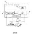
Furthermore, in accordance with another preferred embodiment of the present invention, the anti-arrhythmic therapy is selected from a defibrillating shock therapy, a cardioverting shock therapy, anti-tachycardia pacing therapy, anti-bradycardia pacing therapy, variable energy shock therapy, and combinations thereof.
Furthermore, in accordance with another preferred embodiment of the present invention, the applying of cardiac contractility modulating signals to the heart is terminated prior to or upon the delivering of the anti-arrhythmic therapy to the heart of the patient.
Furthermore, in accordance with another preferred embodiment of the present invention, the applying of cardiac contractility modulating signals to the heart is renewed after the delivering of the anti-arrhythmic therapy to the heart of the patient is terminated.
Furthermore, in accordance with another preferred embodiment of the present invention, the method further includes protecting the electronic circuitry of the cardiac therapy device from high voltages generated during the applying of the anti-arrhythmic therapy to the heart.
Finally, in accordance with another preferred embodiment of the present invention, the method further includes pacing at least one chamber of the heart of the patient.
BRIEF DESCRIPTION OF THE DRAWINGS
The invention is herein described, by way of example only, with reference to the accompanying drawings, in which like components are designated by like reference numerals, wherein:
FIG. 1 is a schematic functional block diagram illustrating a prior art defibrillator device;
FIG. 2 is a schematic diagram illustrating a cardiac contractility modulating device having anti-arrhythmic therapy capabilities, in accordance with a preferred embodiment of the present invention;
FIG. 3 is a schematic diagram illustrating a detail of a cardiac contractility modulating device having anti-arrhythmic therapy capabilities, useful in understanding possible implementation methods of control signals at different levels of a part of the cardiac contractility modulating device of the present invention; and
FIG. 4 is a schematic diagram illustrating a CCM device having capability of applying a plurality of different anti-arrhythmic therapy methods to the heart, in accordance with another preferred embodiment of the present invention.
DETAILED DESCRIPTION OF THE INVENTION
The following terms are used throughout the application:
TermDefinition
ACAlternating Current
AGCAutomatic Gain Control
AICDAutomatic Internal Cardioverter Defibrillator
ATCAutomatic Threshold Control
ATPAnti-Tachycardia Pacing
CCMCardiac Contractility Modulation
CHFCongestive Heart Failure
DCDirect Current
ECDExternal Cardiac Defibrillator
ETCExcitable Tissue Control
ICDInternal Cardiac Defibrillator
LUTLook Up Table
SVTSupra Ventricular Tachycardia
VFVentricular Fibrillation
VTVentricular Tachycardia
Reference is now made toFIG. 1 which is a schematic functional block diagram illustrating a prior art defibrillator device.
Thedefibrillator device1 includes a filter andvoltage protection unit3 which is suitably electrically connected tosensing electrodes4A and4B which are implanted in or about theheart2. The filter and highvoltage protection unit3 may includes various types of filtering circuitry for filtering the electrical signals sensed by thesensing electrodes4A and4B to remove signal components having undesirable frequencies (such as electrical noise at mains frequencies or other filterable noise) and for protecting the other circuitry of thedefibrillator device1 from high voltage signals resulting from the delivery of the electrical defibrillating shocks to theheart2. Thedefibrillator1 further includes a sensing unit8 which is electrically connected to the filter and highvoltage protecting unit3.
The sensing unit8 may include amplification circuitry for amplifying the filtered electrical signals. The output of the sensing unit8 is suitably connected to a detecting circuit which performs the detection of electrical depolarization events representing cardiac activation. The detecting unit may be any analog or digital unit which is capable of detecting cardiac depolarization events by comparing it to a detection threshold as is known in the art or by any other event detection method which is known in the art. For example, the sensing unit8 and the detectingunit10 may be implemented using analog circuitry as disclosed by Dennis A. Brumwell et al. inChapter 14 titled “THE AMPLIFIER: SENSING THE DEPOLARIZATION” of the book titled “IMPLANTABLE CARDIOVERTER DEFIBRILLATOR THERAPY: THE ENGINEERING-CLINICAL INTERFACE”, pp. 275–302, Eds. Mark W. Kroll and Michael H. Lehmann, Kluwer Academic Publishers, USA, 1997, incorporated herein by reference. However, The sensing unit8 and the detectingunit10 may also be implemented by other different analog or digital circuits or any combinations thereof as is known in the art of defibrillators.
Thedefibrillator device1 further includes amicroprocessor unit12 connected to the detectingunit10 to receive therefrom signals representing the detection of cardiac depolarization events. Themicroprocessor unit12 is also connected to Timing unit(s)14 for receiving timing signals therefrom, and to memory unit(s)16. Thememory units16 may be one or more memory devices for storing and retrieving data. The memory unit(s)16 may include read-only memory devices and read-write memory devices for storage and retrieval of data. The timing unit(s)14 and the memory unit(s)16 communicate with themicroprocessor unit12 through adata bus15.
Themicroprocessor12 is also connected to a defibrillatingunit18 which is controlled by themicroprocessor unit12. The defibrillatingshock unit18 is designed to deliver electrical defibrillating shocks to theheart2 throughsuitable defibrillating electrodes6A and6B disposed in or about theheart2. The defibrillatingshock unit18 may typically include a current source such as a battery (not shown), a charging circuit (not shown), and high voltage output switches (not shown) as is known in the art. For example, the defibrillatingshock unit18 may be implemented as disclosed by C. G. Supino in Chapter 8. titled “THE SYSTEM”, pp. 163–172 of the book titled “IMPLANTABLE CARDIOVERTER DEFIBRILLATOR THERAPY: THE ENGINEERING-CLINICAL INTERFACE”, Eds. Mark W. Kroll and Michael H. Lehmann, Kluwer Academic Publishers, USA, 1997, incorporated herein by reference. However, thedefibrillator unit18 may be implemented using any design or circuit for delivering defibrillation shocks to the heart which is known in the art.
Thedefibrillator device1 also includes apower source13 for providing power to the various components of thedevice1. Thepower source13 is suitably operatively connected (connections not shown for the sake of clarity of illustration) to provide electrical energy the components of thedefibrillator device1 as is known in the art. Thepower source13 may be an electrochemical cell or a battery (primary or rechargeable), or the like but may be any other suitable power source for providing electrical power which is known in the art. It is noted that while thepower source13 is shown as included within thedefibrillator device1, thepower source13 may be also disposed externally to thedevice1. For example, thepower source13 may be a power source such as, but not limited to, a conditioned or regulated DC or AC power supply, operatively connected to the mains power supply (not shown) as is known in the art. Such mains powered external defibrillator devices are well known in the art.
It is noted that thedefibrillator device1 ofFIG. 1 is given herein by way of a non-limiting example of a prior art defibrillator and that many other types of defibrillators using different hardware implementations are possible as is known in the art.
Thedefibrillator device1 represents an automatic implantable defibrillator device (AICD). However, other types of defibrillators such as external cardiac defibrillator (ECD) devices are also known in the art.
In operation, the sensing unit8 amplifies the filtered electrical signals sensed by thesensing electrodes4A and4B, the detectingunit10 receives the amplified filtered signals and detects depolarization events, the detection may employ various methods such as threshold crossing detection methods as disclosed by Brumwell et al., including, but not limited to, AGC methods and ATC methods. However any other suitable event detection methods known in the art may also be used for event detection. The detectingunit10 provides to themicroprocessor unit12 detection signals representative of the detection of an event in the sensed amplified signal provided by the sensing unit8. Themicroprocessor unit12 processes the detection signals using suitable processing programs embedded in themicroprocessor unit12 or in the memory unit(s)16 connected thereto. The various processing algorithms are generally referred to as classification algorithms or classification programs. The classification programs process the temporal data of the time of occurrence of the detection signals and classify the sensed cardiac rhythm as belonging to one of a plurality of possible cardiac rhythm categories. In a non-limiting example, the categories may include a range of heart rates defined as normal cardiac rate for a particular patient, an elevated heart rate range classified as a ventricular tachycardia (VT), and another elevated heart rate range classified as a ventricular fibrillation (VF). The various classification methods and algorithms are well known in the art are not the subject matter of the present invention and will therefore; not be disclosed in detail hereinafter. Some exemplary methods of tachy-arrhythmia detection methods are disclosed by Stan M. Bach et al. inChapter 15, titled “TACHYARRHYTHMIA DETECTION”, pp. 303–323, of the book titled “IMPLANTABLE CARDIOVERTER DEFIBRILLATOR THERAPY: THE ENGINEERING-CLINICAL INTERFACE”, Eds. Mark W. Kroll and Michael H. Lehmann, Kluwer Academic Publishers, USA, 1997, incorporated herein by reference.
If a VF episode is detected, themicroprocessor unit12 may, based on such a detection, outputs various control signals to thedefibrillating shock unit18 for initiating the charging of a high voltage capacitor (not shown) included in the defibrillatingunit18 in preparation for delivering a defibrillation shock to the heart. After verification of the detection of VF, further control signals, sent from themicroprocessor unit12 to the defibrillatingunit18, may initiate the delivering of a defibrillating shock to theheart2.
Some prior art defibrillator/cardioverter devices are also capable of delivering Anti-tachycardia pacing (ATP) and cardioversion therapy after detection of VT, as is well known in the art. For example, such devices and methods of delivering ATP and cardioversion therapy are disclosed inChapter 16, titled “ANTI-TACHYCARDIA PACING AND CARDIOVERSION” pp. 325–342, of the book titled “IMPLANTABLE CARDIOVERTER DEFIBRILLATOR THERAPY: THE ENGINEERING-CLINICAL INTERFACE”, Eds. Mark W. Kroll and Michael H. Lehmann, Kluwer Academic Publishers, USA, 1997, incorporated herein by reference. Such devices may utilize pacing circuitry (not shown inFIG. 1 for the sake of clarity of illustration) to deliver various pacing and shock signals to the heart for treating the ventricular tachycardia.
It is noted that the term Anti-arrhythmic devices is used throughout the present application to indicate devices for delivering anti-arrhythmia therapy to the heart, the anti-arrhythmia therapy may include defibrillating shocks suitable for VF termination, anti-arrhythmic pacing therapy suitable for treating tachy-arrhythmias such as supra-ventricular tachycardia (SVT) and other types of ventricular tachycardia (VT), cardioversion therapy, and any combination of the above therapies with pacing pulses for anti-bradycardia therapy.
Reference is now made toFIG. 2 which is a schematic diagram illustrating a cardiac contractility modulating device having anti-arrhythmic therapy capabilities, in accordance with a preferred embodiment of the present invention.
Theanti-arrhythmic CCM device30 includes ananti-arrhythmic therapy unit38 and an aCCM unit40. Theanti-arrhythmic therapy unit38 is operatively connected to theCCM unit40 for receiving control signals therefrom. Theanti-arrhythmic therapy unit38 is connectable tosensing electrodes34A and34B for sensing cardiac depolarization events as disclosed hereinabove for prior art defibrillating devices. Theanti-arrhythmic therapy unit38 is also connectable to a pair oftherapy delivering electrodes32A and32B, for delivering anti-tachycardia therapy to theheart2 through theelectrodes32A and32B as is known in the art and disclosed hereinabove. Theanti-arrhythmic CCM device30 also includes apower source165 for providing power to the various components of theanti-arrhythmic CCM device30. Thepower source165 is suitably operatively connected to the various components of the anti-arrhythmic CCM device30 (connections not shown for the sake of clarity of illustration) to provide electrical energy the components of theanti-arrhythmic CCM device30, as is known in the art. Thepower source165 may be an electrochemical cell or a battery (primary or rechargeable), or the like but may be any other suitable power source for providing electrical power which is known in the art. It is noted that while thepower source165 is shown as included within theanti-arrhythmic CCM device30, thepower source165 may be also disposed externally to theanti-arrhythmic CCM device30. For example, thepower source165 may be a power source such as, but not limited to, a conditioned or regulated DC or AC power supply, operatively connected to the mains power supply (not shown), as is known in the art.
For example, in accordance with one preferred embodiment of the present invention, theanti-arrhythmic therapy unit38 is a defibrillating shock unit and theelectrodes32A and32B are defibrillation electrodes suitable for delivering defibrillating shocks to theheart2, as is known in the art and disclosed hereinabove.
Alternatively, in accordance with another preferred embodiment of the present invention, theanti-arrhythmic therapy unit38 is an energy cardioverting shock unit and theelectrodes32A and32B are cardiovertion electrodes suitable for delivering cardioverting shocks to theheart2, as is known in the art and disclosed hereinabove.
In accordance with yet another preferred embodiment of the present invention, theanti-arrhythmic therapy unit38 is a unit capable of delivering anti-tachycardia pacing (ATP) therapy and theelectrodes32A and32B are pacing electrodes suitable for delivering ATP therapy pulses to theheart2, as is known in the art and disclosed hereinabove.
Furthermore, accordance with yet another preferred embodiment of the present invention, theanti-arrhythmic therapy unit38 is a multi-modal anti-arrhythmic therapy unit capable of delivering cardioverting shock therapy, anti-tachycardia pacing (ATP) therapy, and defibrillating shock therapy. In such a case, more than one pair of therapy delivering electrodes (not shown) may need to be connected to theanti-arrhythmic therapy unit38. For example, theelectrodes32A and32B may be pacing electrodes suitable for delivering ATP therapy pulses to theheart2, as is known in the art and disclosed hereinabove, and additional electrodes (not shown) or electrodes pairs (not shown) may be suitably connected to theanti-arrhythmic therapy unit38, such as defibrillating electrodes (not shown) and/or defibrillating/cardioverting electrodes (not shown).
TheCCM unit40 is connectable to a pair ofCCM electrodes36A and36B (also known as ETC electrodes) and is capable of delivering CCM signals (also known in the art as ETC signals) to the heart through theCCM electrodes36A and36B to modulate cardiac contractility as disclosed by Ben Haim et al. and by Mika et al. in the PCT publications and applications and in the Co-pending patent applications referenced hereinabove. It is noted that, theanti-arrhythmic therapy unit38 may be any anti-arrhythmia therapy device known in the art and may be implemented as an analog unit, a digital unit or a hybrid analog and digital unit.
It will be appreciated by those skilled in the art that theanti-arrhythmic CCM device30 ofFIG. 2 may also be adapted to include a pacing unit (not shown). Such a pacing unit may be used in conjunction with suitable pacing electrodes (not shown) for pacing theheart2, for example, in patients in need of anti-bradycardia pacing. Additionally, the pacing unit (not shown) may be integrated in theanti-arrhythmic therapy unit38 such that it may be used for delivering ATP therapy if the need for such therapy is detected by theanti-arrhythmic therapy unit38, as is known in the art and disclosed in U.S. Pat. No. 4,830,006 to Haluska et al.
It is noted that while theanti-arrhythmic therapy unit38, is illustrated as being connected to a single pair ofsensing electrodes34A and34B, a single pair ofelectrodes32A and32B for delivering anti-tachycardia therapy to theheart2, and a single pair of CCM electrodes for delivery of CCM signals to theheart2, many other electrode configurations and combinations are possible which are all considered to be within the scope of the present invention. For example, theanti-arrhythmic therapy unit38 may be connected to more than one CCM delivering electrode pair or electrodes (not shown) for delivering CCM signals to more than one cardiac region. In another example, 
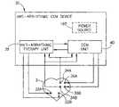
more than one pair of sensing electrodes or a plurality of single sensing electrodes (not shown) may be used for enabling multi chamber sensing and/or pacing, such multi-electrode configurations are disclosed in the above referenced, PCT publications to Ben Haim et al. and in co-pending U.S. patent application Ser. Nos. 09/276,460, 09/328,068 and 09/338,649 to Mika et al., and in the corresponding PCT applications.
It is noted that many types of sensing electrodes, pacing electrodes, shock therapy delivering electrodes may be used in conjunction with theanti-arrhythmic CCM device38 ofFIG. 2. Such electrodes are known in the art and may also be commercially obtained. The electrode types have to be suitably adapted to the design and implementation of the deviceanti-arrhythmic CCM device38. For example if thedevice38 is adapted for use in an intensive care unit it may use epicardial electrodes or other external types of electrodes. In chronically implanted devices, the electrodes may be intracardiac electrodes adapted for sensing, pacing, defibrillation shock delivery electrodes or any other types of anti-arrhythmia therapy electrodes known in the art.
Preferably, theanti-arrhythmic therapy unit38 and the CCM unit are both in communication with a common microprocessor unit (not shown inFIG. 2, for the sake of clarity of illustration). In such a case, the microprocessor unit (not shown) controls the delivery of CCM signals by theCCM unit40 and also sends control signals to theanti-arrhythmic therapy unit38. The control signals sent from the microprocessor unit (not shown) control theanti-arrhythmic therapy unit38 to prevent the CCM signal induced electrical artifacts from interfering with the detection of cardiac arrhythmias as is disclosed in detail hereinafter. Alternatively, theanti-arrhythmic therapy unit38 and theCCM unit40 may each include a dedicated microprocessor unit (the microprocessor units are not shown inFIG. 2, for the sake of clarity of illustration). In the latter case the microprocessor unit (not shown) of theanti-arrhythmic therapy unit38 is in communication with the microprocessor unit (not shown) of theCCM unit40 to provide the microprocessor unit of theanti-arrhythmic therapy unit38 with data representative of the time of delivery of CCM signals by theCCM unit40. This data is processed by the microprocessor of theanti-arrhythmic therapy unit38, or by the microprocessor of theCCM unit40 or by both of these microprocessors to prevent the interference of the CCM signal induced electrical artifacts from interfering with the detection of cardiac arrhythmias as is disclosed in detail hereinafter.
Briefly, in accordance with a preferred embodiment of the present invention the control signals may be used to prevent the sensing of CCM signal induced artifacts at the sensing level.
In accordance with another preferred embodiment of the present invention the control signals may be used to prevent the sensing of CCM signal induced artifacts at the detecting level.
In accordance with yet another preferred embodiment of the present invention the control signals may be used to prevent the sensing of CCM signal induced artifacts at the sensing and the detecting level simultaneously.
Alternatively, In accordance with yet another preferred embodiment of the present invention the control signals may be used to prevent the CCM signal induced electrical artifacts from interfering with the detection of cardiac arrhythmias, not by preventing the sensing or the detecting of the CCM signal induced electrical artifact but by correcting or compensating the error introduced by detection of the CCM induced artifacts as cardiac events at the arrhythmia classification program level. This correction or compensation is achieved computationally by suitably processing the control signals indicative of the delivery of an ETC signal.
In operation, theCCM unit40 may operate to deliver CCM signals to the heart through theCCM electrodes36A and36B or through any other pair (not shown) or pairs (not shown) of electrodes applied to more than one cardiac site. The pair ofsensing electrodes34A and34B may be commonly used for feeding the sensed signals to the sensing unit (not shown) of theanti-arrhythmic therapy unit38 and to the sensing unit (not shown) of theCCM unit40. Alternatively, different separate pairs of electrodes (not shown) may be used for sensing by each of theanti-arrhythmic therapy unit38 and theCCM unit40. Prior to the delivery of CCM signals to theheart2, theCCM unit40 or the microprocessor (not shown inFIG. 2) which controls theCCM unit40 delivers control signals to theanti-arrhythmic therapy unit38. These control signal are related to the delivery of the CCM signals and are used by theanti-arrhythmic therapy unit38 to disable the sensing of the CCM related electrical artifacts or to disable the detection of these artifacts as cardiac depolarization events.
It is noted that, additional control signals may also be delivered to theanti-arrhythmic therapy unit38 during the delivery of a CCM signal to the heart if the method of filtering the artifact signal is employed at the level of a signal filtering unit (not shown) as is disclosed in more detail hereinafter.
Reference is now made toFIG. 3 which is a schematic diagram illustrating a detail of a cardiac contractility modulating device having anti-arrhythmic therapy capabilities, useful in understanding possible implementation methods of control signals at different levels of a part of the cardiac contractility modulating device of the present invention.
InFIG. 3, ananti-arrhythmic module50 is illustrated which is integrated within a CCM anti-arrhythmic device51 (only a part of thedevice51 is shown, for the sake of clarity of illustration). Themodule50 includes a filtering andvoltage protection unit53, which receives input signals from sensing electrodes (not shown) disposed in or about the heart and is connected to asensing unit58. The filtering andvoltage protection unit53 is operative to filter the signals from the sensing electrodes and to protect thesensing unit58 connected thereto from the high energy defibrillating shock related signals, as is known in the art and disclosed hereinabove.
Thesensing unit58 amplifies the signal received from the sensing electrodes (not shown) Thesensing unit58 is connected to a detectingunit60 which detects depolarization events in the filtered amplified signals at the output of thesensing unit58 as disclosed in detail hereinabove for theprior art defibrillator1 ofFIG. 1. The detectingunit60 is operatively connected to amicroprocessor unit62.
Themicroprocessor unit62 is operatively connected to ananti-arrhythmic therapy unit68 and controls the delivery of anti-arrhythmic therapy signals to theheart2 by controlling the output of anti-arrhythmic therapy signals fromanti-arrhythmic therapy unit68. Theanti-arrhythmic therapy unit68 may be any type of device or unit known in the art for delivering one or more anti-arrhythmic type of therapy to the heart. For example, theanti-arrhythmic therapy unit68 may be a defibrillator unit, a cardioverter/defibrillator unit, or a multi-modal cardiac therapy unit similar to the cardiac stimulator disclosed by Haluska et al. in U.S. Pat. No. 4,830,006, or any other type of anti-arrhythmic therapy unit known in the art.
Theanti-arrhythmic module50 receives control signals from other parts (not shown in detail) of theCCM device51 within which it is integrated. The control signals may be received from the CCM unit (not shown) which is also integrated within theCCM device51, or from a microprocessor or controller unit (not shown) which is included in or communicating with the CCM unit (not shown). Alternatively, themicroprocessor unit62 may control theentire CCM device51, including the CCM unit (not shown).
The prevention of interference of the sensed CCM signal induced electrical artifacts may be implemented in various ways. In accordance with one preferred embodiment of the present invention, the prevention of interference is implemented at the sensing level. In this implementation, suitable control signals are sent to thesensing unit58 prior to the delivery of each CCM signal to theheart2. These control signals are represented by the dashedarrow70. Each of the received control signals causes thesensing unit58 to become refractory to incoming input signals from the filtering andvoltage protecting unit53. The timing and duration of the control signals are such that thesensing unit58 becomes refractory to incoming input signals before the delivery of the CCM signal to the heart and stays refractory for a refractory period having a duration that is sufficient to prevent the CCM induced electrical artifact from being detected as an event by thedetection unit60. Thus, the refractory period of thesensing unit58 may last longer than the duration of the CCM signal delivered to the heart, to accommodate for the precise shape, amplitude, polarity and duration of the CCM induced artifact as it is sensed by thesensing unit58. The duration of the refractory period may be a fixed duration, or may be a preset duration, that may be programmed, telemetrically or non-telemetrically, into the memory (not shown) of theCCM device51 based on actual determination of the artifact parameters obtained from each individual patient in a recording and measurement session taking place after implantation of the electrodes in the patient.
Thus, the determination of the duration of the refractory period is done such as to take into account the maximal duration of CCM signal induced electrical artifact which may be picked up by the sensing electrodes (not shown) and is capable of being erroneously detected as a true event in the patient in which thedevice51 is operative. This maximal duration is preferably determined empirically for each patient by a physician or cardiologist after collecting data in a test session of thedevice51 in the patient taking place after electrode implantation. It is also preferred to add a certain safety margin by increasing the refractory period above the value of the empirically determined maximal duration, this safety margin may be advantageous in preventing erroneous event detection in cases in which the CCM signal induced electrical artifact has large variability or may show drift over extended periods of time due to electrode movements or other reasons.
It is noted that some CCM devices may apply to the heart of the same patient different types of CCM signals having different or varying signal parameters, in response to different cardiac conditions or for changing and controlling the contractility and cardiac output of the heart. The CCM signal parameters that may vary include, but are not limited to, CCM signal amplitude, CCM signal duration, CCM signal waveform, and CCM signal polarity.
Thus, if the refractory period duration is a fixed duration, care must be taken to select such a duration that is long enough to ensure that any type of CCM signal which thedevice51 is capable of delivering to the heart will not result in erroneous (spurious) detection of the CCM signal induced electrical artifact as a detected event. Alternatively, the refractory period may be a variable refractory period and thedevice51 may be adapted to select a particular value of a refractory period duration from a preprogrammed look up table (LUT), which includes different refractory period duration values associated with different CCM signal types. The data in the LUT may be obtained by empirical tests performed in the patient in a testing or data collection session after implantation of the electrodes in each individual patient. Such tests may record the parameters of the electrical artifacts associated with the delivery of cardiac contractility modulating signals having different parameters. The parameters of the recorded electrical artifacts may then be used to determine appropriate refractory period parameter sets for each different type of deliverable CCM signal to prevent erroneous detection of the electrical artifacts as cardiac events, as disclosed in detail hereinabove. This method has the advantage of being individually adapted to each patient, and of enabling the control of the refractory period on a beat by beat basis.
Thesensing unit58 may receive the control signals from the microprocessor unit which controls the activation of the CCM unit. In the embodiment in which thedevice51 includes only onemicroprocessor unit62, thesensing unit58 receives the control signals from themicroprocessor unit62. If the CCM unit (not shown) of thedevice51 is controlled by a second microprocessor or controller (not shown) which is not themicroprocessor62, the control signals for controlling the refractory period of thesensing unit58 may be received from the second microprocessor or controller.
In accordance with another preferred embodiment of the present invention, the prevention of interference is implemented at the detecting level. In this implementation, suitable control signals are sent to the detectingunit60 prior to the delivery of each CCM signal to theheart2. These control signals are represented by the dashedarrow72. Each received control signal causes the detectingunit60 to become refractory to incoming input signals from thesensing unit58. The timing and duration of the control signals are such that the detectingunit60 becomes refractory to incoming input signals before the delivery of the CCM signal to the heart and stays refractory for a refractory period having a duration that is sufficient to prevent the CCM induced electrical artifact from being detected as an event by thedetection unit60. Thus, the refractory period of the detectingunit60 may last longer than the duration of the CCM signal delivered to the heart, to accommodate for the precise shape, amplitude and duration of the CCM induced artifact as it is sensed by thesensing unit58. The duration of the refractory period of detectingunit60 may be a fixed duration, or may be a preset duration that may be programmed, telemetrically or non-telemetrically, into the memory (not shown) of thedevice51 based on actual determination of the maximal artifact parameters obtained from each individual patient in a recording and measurement session taking place after implantation of the electrodes in the patient.
Similar to the refractory period of thesensing unit58 disclosed hereinabove, if the refractory period duration of the detectingunit60 is a fixed duration, care must be taken to select such a duration that is long enough to ensure that any type of CCM signal which thedevice51 is capable of delivering to the heart will not result in erroneous (spurious) detection of the CCM signal induced electrical artifact as a detected event. Alternatively, the refractory period of the detectingunit60 may be a variable refractory period and thedevice51 may be adapted to select a particular value of a refractory period duration from a preprogrammed look up table (LUT) which includes different refractory period duration values associated with different CCM signal types. The data in the LUT may be obtained by empirical tests performed in the patient in a testing or data collection session after implantation of the electrodes in each individual patient.
Such tests may record the parameters of the electrical artifacts associated with the delivery of cardiac contractility modulating signals having different parameters. The parameters of the recorded electrical artifacts may then be used to determine appropriate refractory period parameter sets for each different type of deliverable CCM signal to prevent erroneous detection of the electrical artifacts as cardiac events, as disclosed in detail hereinabove. This method has the advantage of being individually adapted to each patient, and of enabling the control of the refractory period on a beat by beat basis. The method is adapted for use in CCM devices which are capable of delivering variable CCM signals and of adapting one or more of the CCM signal parameters (such as but not limited to the amplitude, duration, wave shape, and polarity of the CCM signal) for controlling the effect of the CCM signals on the cardiac contractility and/or on the cardiac output. In accordance with a preferred embodiment of the present invention, since in such CCM devices, the CCM signals parameters may be varied in time according to, inter alia, detected patient need and patient metabolic state, themicroprocessor unit62 may select from the LUT the appropriate refractory period parameters which are associated with the parameters of the particular CCM signal which is about to be delivered to the heart of the patient under the control of themicroprocessor unit62. This method has the advantage of being individually adapted to each patient and of flexibly and automatically allowing the selection of refractory period duration which is adapted to the parameters of the currently delivered CCM signal parameters, thus, allowing control of CCM signal parameters while still efficiently preventing erroneous detection of the CCM induced electrical artifacts as true events.
The detectingunit60 may receive the control signals from the microprocessor unit which controls the activation of the CCM unit. In the embodiment in which thedevice51 includes only onemicroprocessor unit62, the detectingunit60 receives the control signals from themicroprocessor unit62. If the CCM unit (not shown) of thedevice51 is controlled by a second microprocessor or controller (not shown) which is not themicroprocessor62, the control signals for controlling the refractory period of thedetection unit60 may be received from the second microprocessor or controller.
It is noted that, themicroprocessor unit62 may be a microprocessor unit which is dedicated to themodule50 or may be a microprocessor unit which is commonly used to control the operation of theentire CCM device51.
Furthermore, in accordance with another preferred embodiment of the present invention, the control signals may cause thesensing unit58 and the detectingunit60 to become refractory as disclosed hereinabove. This implementation has the advantage that more power is conserved by putting both thesensing unit58 and the detectingunit60 into a refractory state since the power consumption of each of these units is smaller in the refractory period, resulting in increasing the useful life of the battery (not Shown) or power source (not shown) which powers thedevice51.
It is further noted that the preventing of the sensing and/or the detecting of CCM induced electrical artifacts as event may also be achieved by controlling the filtering andvoltage protection unit53 such as by putting it into a refractory period or by suitably controlling the filtering properties thereof such that all the signals fed into thesensing unit58 including the CCM related electrical artifact signals are strongly attenuated during a period equivalent to the duration of the above disclosed refractory period. If the method of preventing the sensing and/or the detecting of CCM induced electrical artifacts as true events is achieved by controlling the filtering characteristics such as but not limited to the frequency response characteristics of the filtering andvoltage protection unit53, themicroprocessor unit62 which controls the filtering andvoltage protection unit53 and/or the CCM unit (not shown) of thedevice51 may also provide the filtering andvoltage protection unit53 with data related to the CCM signal parameters, such as but not limited to CCM signal amplitude, CCM signal duration, CCM signal waveform, and CCM signal polarity. This CCM signal parameter related data may be provided by themicroprocessor unit62 to the filtering andvoltage protection unit53 before and/or during the time of delivery of the CCM signals to the heart. The CCM signal parameter related data is useful particularly in cases where one or more of the parameters of the CCM signals is dynamically varied under control of themicroprocessor62, during the delivery of CCM therapy, because such CCM signal parameter related data allows the control of the filtering characteristics of the filtering andvoltage protection unit53 on a beat by beat basis for CCM signals having dynamically variable parameters.
It is noted that the filtering andvoltage protection unit53 may be adapted to function as a controlled matched filter which is adapted to reject the CCM signal induced electrical artifact based on a fixed or dynamically varying template or data adapted for maximal rejection of the predicted waveform and/or frequency content of the CCM induced electrical artifact. Such template or data may be supplied to the filtering andvoltage protection unit53 by themicroprocessor62 in accordance with the data of the type and parameters of the CCM signal scheduled to be delivered to the heart in accordance with the CCM delivery control program operative on themicroprocessor unit62.
In accordance with still another preferred embodiment of the present invention, the prevention of interference of the CCM induced electrical artifact signals is implemented at the classification level. In this implementation, thesensing unit58 and the detectingunit60 are not put into a CCM signal related refractory period. Themicroprocessor62 may receive control signals represented by the dashedarrow74 from the CCM unit. These control signals are indicative of the timing of delivery of the CCM signals to the heart. Alternatively, in cases wherein themicroprocessor62 also controls the activation of the CCM unit (not shown) of thedevice51, themicroprocessor62 has internal data therewithin indicative of the computed timing of activation of the CCM unit. In both of these alternatives themicroprocessor unit62 uses the data indicative of the timing of the delivery of CCM signals for computationally correcting or compensating for the possible errors in computing the heart rate which may be induced by spurious detection of the CCM signal induced artifact as “true” depolarization events. In a non-limiting example, the classification program may subtract the known number of CCM signals delivered to the heart within a certain number of cardiac beat cycles from the total number of events detected by the detectingunit60 within the same beat cycles, preventing possible heart rate classification errors which may have been introduced by an erroneous number of detected events, had the correction not been applied.
It will be appreciated that the correction methods which may be used for correcting or compensating for erroneous event detection prior to processing the data for classification and arrhythmia detection must be adapted to the specific methods, programs and algorithms which are used for processing the event detection data and for the classification of heart rates for arrhythmia detection and classification.
It is noted that, while the method of triggering or inducing a refractory period in one or more of thesensing unit58, the filtering andvoltage protection unit53 and the detectingunit60 may provide an adequate solution to the problem of erroneous CCM induced artifact detection, care must be taken to ensure that the blanking of one or more of thesensing unit58, the filtering andvoltage protection unit53 and the detectingunit60 during the imposed refractory period will not by itself produce undesirable errors in the estimation of the heart rate due to the cessation of detection of any electrical events within the imposed refractory period duration. Typically, the CCM signal duration may vary between approximately 20–50 milliseconds (although lower or higher duration values may also be used). Some VT episodes in human cardiac patients may exhibit R—R intervals of approximately 250–300 millisecond duration, Therefore, when the above disclosed refractory period method is used, the blanking or refractory period may occupy approximately 20% of the total beat cycle. Thus, there is a possibility that a true event may occur within the refractory period and will therefore not be detected, which may cause errors in the determination of the heart rate. Such errors may eventually lead to wrong classification of the heart rate by the classification methods or classification algorithms used and may also undesirably delay or in extreme cases even prevent the delivery of the proper anti-arrhythmic therapy by theanti-arrhythmic module50 of thedevice51. For example, under such circumstances, an episode of VT may be missed of misclassified as allowable tachycardia, and VF may be misclassified as VT leading to delay in delivery of the proper type of anti-arrhythmic therapy or to failure to deliver any tachy-arrhythmic therapy.
In order to prevent or at least to reduce the probability of the misclassification and the resulting delay or failure of the proper application of anti-arrhythmic therapy, thedevice51 may be adapted to use a threshold based method to disable the delivery of CCM signals to the heart when the detected heart rate exceeds a certain threshold. Thus, in accordance with another preferred embodiment of the present invention, thedevice51 continuously determines the heart rate and classifies the heart rate, in accordance with any sensing, detecting, and anti-arrhythmic heart rate classification methods or algorithms known in the art. Simultaneously, the CCM unit or circuitry operates to detect the need for CCM therapy and to control the delivery of CCM signals to the heart, in accordance with any of the methods of CCM signal delivery known in the art or disclosed in any of the above referenced published or co-pending patent applications disclosed hereinabove. If the heart rate exceeds a certain threshold level, this is classified as a suspected tachy-arrhythmia and themicroprocessor62 disables the delivery of CCM signals to the heart within a time period which is referred to as the “CCM signal free” period, hereinafter. Thedevice51 then continues to determine the heart rate within this CCM signal free period, in the absence of CCM signal delivery. Thedevice51 analyzes and classifies the heart rate in accordance with the classification criteria based on the detection data obtained by thedevice51 during the CCM signal free period. Thedevice51 then determines whether any type of anti-arrhythmia therapy is to be delivered to the heart based on the classification of the heart rate obtained in the CCM free period.
If the classification of the heart rate obtained in the CCM free period indicates the need to deliver any type of anti-arrhythmic therapy, thedevice51 continues the disabling of CCM signal delivery and initiates the delivery of the required anti-arrhythmic therapy, and continues to deliver any indicated anti-arrhythmic therapy and to determine the heart rate as is known in the art until the anti-arrhythmic therapy is terminated. If the anti-arrhythmic therapy is terminated by thedevice51, thedevice51 enables the delivery of CCM signals to the heart.
If the classification of the heart rate obtained in the CCM free period does not indicate a need to deliver any type of anti-arrhythmic therapy, thedevice51 enables the delivery of CCM signals.
Thus, in the above disclosed method of operation of thedevice51, the anti-arrhythmic detection and classification program, sub-routine or algorithm takes priority over the CCM delivery control program, sub-routine or algorithm, enabling it to override, interrupt or disable the CCM signal delivery even under conditions in which the delivery of CCM signals is called for by the CCM delivery control program to modify cardiac contractility and or cardiac output.
Reference is now made toFIG. 4 which is a schematic diagram illustrating a CCM device having capability of applying a plurality of different anti-arrhythmic therapy methods to the heart.
TheCCM device100 ofFIG. 4 includes apacing unit102 connectable to one ormore pacing electrodes104. Thepacing unit102 is suitably connected to a microprocessor orcontroller106. Themicroprocessor106 controls thepacing unit102 to deliver pacing pulses to the heart (nor shown) for performing anti-bradycardia pacing if necessary, as is well known in the art. TheCCM device100 also includes aCCM unit108 capable of delivering CCM signals (also known in the art as ETC signals). TheCCM unit108 is connectable to one ormore CCM electrodes110 for delivering CCM signals to the heart. TheCCM device100 also includes sensingunits112 connectable to one ormore sensing electrodes114 for sensing electrical signals at or about the heart. TheCCM device100 also includes one or more detectingunits116 which are connected to the sensing unit(s)112 for receiving amplified sensed signals therefrom and to themicroprocessor106 for providing control signals thereto indicative of detecting depolarization events in the heart. TheCCM device100 also includes ananti-tachyarrhythmic unit118 which is connected to themicroprocessor106 for receiving control signals therefrom. Theanti-tachyarrhythmic unit118 is connectable to one or moreanti-arrhythmic therapy electrodes120 for delivering anti-arrhythmic therapy to the heart.
Thedevice100 also includes apower source165 for providing power to the various components of thedevice100. Thepower source165 is suitably operatively connected (connections not shown for the sake of clarity of illustration) to provide electrical energy the components of thedevice100 as is known in the art. Thepower source165 may be an electrochemical cell or a battery (primary or rechargeable), or the like, but may also be any other suitable power source for providing electrical power which is known in the art. It is noted that while thepower source165 is shown as included within thedevice100, thepower source165 may be also disposed externally to thedevice100. For example, thepower source165 may be a power source such as, but not limited to, a conditioned or regulated DC or AC power supply, operatively connected to the mains power supply (not shown) as is known in the art.
Themicroprocessor unit106 controls the output of anti-arrhythmic therapy signals from theanti-tachyarrhythmic unit118. Theanti-tachyarrhythmic unit118 may be any type of device or unit known in the art for delivering one or more anti-arrhythmic type of therapy to the heart. For example, theanti-arrhythmic therapy unit118 may be a defibrillator unit, a cardioverter/defibrillator unit, or a multi-modal cardiac therapy unit similar to the cardiac stimulator disclosed by Haluska et al. in U.S. Pat. No. 4,830,006, or any other type of anti-arrhythmic therapy unit known in the art.
Theanti-arrhythmic electrodes120 are adapted to be suitable for the delivery of the specific types of anti-arrhythmic therapy signals which theanti-tachyarrhythmic unit118 is capable of applying to the heart. For example, theanti-arrhythmic electrodes120 may comprise one or more electrodes adapted for delivering signals to the heart such as, but not limited to, high energy defibrillating shock signals, non-defibrillating cardioversion signals, ATP signals, and the like. Themicroprocessor unit106 is suitably connected to adata bus122. Thedata bus122 is connected to one ormore memory units124, one ormore timing units126 and to atelemetry unit128. Themicroprocessor unit106 may store and retrieve data on thememory units124. Thememory units124 may include memory units including embedded read only data such as programs for operating themicroprocessor unit106 to control and operate thedevice100. Thememory units124 may also include memory units having read and write capabilities for data storage and retrieval (such as, but not limited to, RAM memory units) for storing, inter alia, patient data, computational results, and programming instructions which are telemetrically or non-telemetrically communicated to theCCM device100. The timingunits126 provide timing or clocking signals to themicroprocessor unit106 over thedata bus122. Themicroprocessor unit106 communicates with thememory units124, the timing unit(s)126 and thetelemetry device128 over thedata bus122. Thetelemetry device128 is optional and enables wireless data transmission to and from a telemetry transceiver unit (not shown) disposed outside the patient (not shown).
In operation, the delivery of CCM signals to the heart by theCCM unit108 is controlled based on the output of the detectingunits112 to themicroprocessor unit106, as disclosed in detail in the above referenced co-pending U.S. patent application Ser. Nos. 09/276,460, 09/328,068 and 09/338,649 to Mika et al., and in the corresponding PCT applications.
In accordance with one preferred embodiment of the present invention, theCCM unit108 provides control signals to one or more of thesensing units112 and/or to one or more of the detectingunits116 for inducing refractory periods in the sensing unit(s)112 or in the detectingunits116 or in the sensing unit(s)112 and the detectingunits116 as disclosed in detail hereinabove, for preventing interference of CCM induced electrical artifact signals with the sensing or the detecting or both sensing and detecting of depolarization events as disclosed hereinabove. The control signals may be (optionally) provided from theCCM unit108 to thesensing unit112 as represented by the dashedarrow130. The control signals may also be (optionally) provided from theCCM unit108 to the detecting unit(s)116 as represented by the dashedarrow132. The control signals may also be simultaneously provided to the sensing unit(s)112 and to the detecting unit(s)116 as disclosed hereinabove.
Alternatively, in accordance with another preferred embodiment of the present invention, the control signals may be provided from themicroprocessor unit106 to the sensing unit(s)112 or to the detecting unit(s)116 or to both of the sensing unit(s)112 and the detecting unit(s)116 as disclosed in detail hereinabove. The sensing unit(s)112 or the detecting unit(s)116 or both the sensing unit(s)112 and the detecting unit(s)116 may be switched by the control signals into a refractory state as disclosed hereinabove.
Furthermore, in accordance with yet another preferred embodiment of the present invention, themicroprocessor unit106 may use the data of the timing of the delivery of CCM signals to the heart for performing a correcting or compensating method or computation in order to prevent errors at the classification level as disclosed in detail hereinabove.
It is noted that, thesensing units112 may include a plurality of sensing units operative for providing sensing at different sites of the heart, such as but not limited to, the right atrium, the right ventricle, the left ventricle of the heart and other different cardiac sites in order to provide the various sensing configurations required for the operation of any of the specific type or configuration of theanti-tachyarrhythmic unit118 which is implemented in thedevice100, any of the specific configurations or modes of anti-bradycardia pacing therapy which may be implemented on thepacing unit102, and any of the specific sensing configurations required for operating theCCM unit108, including but not limited to, the sensing methods and configurations disclosed in the PCT publications to Ben Haim et al. and in the co-pending U.S. patent application Ser. Nos. 09/276,460, 09/328,068 and 09/338,649 to Mika et al. referenced hereinabove, and in the corresponding PCT applications.
In order to prevent or at least to reduce the probability of the misclassification and the resulting delay or failure of the proper application of anti-arrhythmic therapy, thedevice100 is adapted to use the threshold based method to disable the delivery of CCM signals to the heart when the detected heart rate exceeds a certain threshold as is disclosed in detail for thedevice51 ofFIG. 3.
Thus, in accordance with a preferred embodiment of the present invention, thedevice100 continuously determines the heart rate and classifies the heart rate, in accordance with any sensing, detecting, and anti-arrhythmic heart rate classification methods or algorithms known in the art. Simultaneously, theCCM unit108 and themicroprocessor unit106 operate to detect the need for CCM therapy and to control the delivery of CCM signals to the heart, in accordance with any of the methods of CCM signal delivery known in the art or disclosed in any of the above referenced published or co-pending patent applications disclosed hereinabove. If the heart rate exceeds a certain threshold level, this heart rate is classified as a suspected tachy-arrhythmia and themicroprocessor106 disables the delivery of CCM signals to the heart within the CCM signal free period, disclosed hereinabove.
Typically, the heart rate is determined by determining the R—R interval as is known in the art, but other methods may also be used.
The threshold level value for determining the suspected tachy-arrhythmia is preferably individually adapted to each patient and then set by programming it into the memory unit(s)124 by communicating it telemetrically or non-telemetrically to thedevice100 as is known in the art. This individual determination and setting of the value of the heart rate threshold level for suspected tachy-arrhythmia has the advantage of enabling to fine-tune the operation of thedevice100 such as to find an appropriate balance between minimizing undesired masking, delayed detection, or non-detection of therapy requiring tachy-arrhythmic episodes due to use of the above disclosed refractory period and maximizing the upper heart rate level at which CCM therapy may still be delivered to the heart.
The precise value of the acceptable threshold level may be influenced, inter alia, by the type of cardiac disorder of the patient, the presence or absence of cardio-therapeutic drugs used by the patient, and data collected in the same patient under normal cardiac conditions, SVT conditions, VT conditions and possibly VF conditions. The setting of the threshold value may have to be performed by a physician or cardio-physiologist based on study of such patient conditions and on the degree of desired CCM modification for that patient.
Typically, an exemplary non-limiting value for the heart rate threshold level is 150 heart beats per minute. However, other larger or smaller threshold level values may also be used, according to the individual patient cardiac conditions.
The disabling of the delivery of CCM signals is performed by themicroprocessor unit106 by sending appropriate control signal or signals to theCCM unit108. Thedevice100 then continues to determine the heart rate within this CCM signal free period in the absence of CCM signal delivery. Themicroprocessor106 of thedevice100 analyzes and classifies the heart rate in accordance with the classification criteria based on the detection signal data which are sent from one or more of the detectingunits116 to themicroprocessor unit106 during the CCM signal free period. Themicroprocessor106 of thedevice100 then determines whether any type of anti-arrhythmia therapy is to be delivered to the heart based on the classification of the heart rate obtained in the CCM free period.
If the classification of the heart rate resulting from the processing of the detection data obtained in the CCM free period indicates the need to deliver any type of anti-arrhythmic therapy, themicroprocessor106 continues the disabling of CCM signal delivery and initiates the delivery of the required anti-arrhythmic therapy by sending appropriate control signals to theanti-tachyarrhythmic unit118, and continues to deliver any indicated anti-arrhythmic therapy and to determine and classify the heart rate as is known in the art until the anti-arrhythmic therapy is terminated. If the anti-arrhythmic therapy is terminated by themicroprocessor106, themicroprocessor106 enables the delivery of CCM signals to the heart by sending a suitable enabling control signal to theCCM unit108.
If the classification of the heart rate obtained in the CCM free period does not indicate a need to deliver any type of anti-tachyarrhythmic therapy, themicroprocessor106 enables the delivery of CCM signals to the heart by sending a suitable enabling control signal to theCCM unit108.
Similar to the method disclosed for thedevice51 ofFIG. 3, the anti-tachyarrhythmia detection and classification program, sub-routine, or algorithm operative on themicroprocessor unit106 takes priority over the CCM delivery control program, sub-routine, or algorithm which is also operative on themicroprocessor unit106, enabling it to override, interrupt or disable the CCM signal delivery even under conditions in which the delivery of CCM signals is called for by the CCM delivery control program to modify cardiac contractility and or cardiac output.
Preferably, but not necessarily, the detection of bradycardia and the delivery of anti-bradycardia pacing therapy is performed by pacing programs, subroutines or algorithms which are operative on themicroprocessor106 as is known in the art and disclosed hereinabove.
It is noted that, if the sensing unit(s)112 include a plurality of sensing units operative for providing sensing of signals at different sites of the heart, thesensing units112 may be, but need not necessarily be, identical units and may differ from each other to be adapted for sensing specific signals.
Similarly if the detectingunits116 include a plurality of detecting units operative for providing event detecting for signals sensed at different sites of the heart, the detectingunits116 may be, but need not necessarily be, identical units and may differ from each other to be adapted for detection of specific sensed and amplified signals.
It is noted that theCCM devices30,51 and100 ofFIGS. 2,3 and4, respectively, may be adapted for acute implantation in a patient for short term patient monitoring and therapy treatment such as for temporary use in intensive care hospitalized patients. Alternatively, theCCM devices30,51 and100 of FIGS.2,3 and4, respectively, may be adapted for used as implantable devices for chronic implantation.
It will be appreciated that the preferred embodiments disclosed hereinabove and illustrated in the drawings are given by way of example only and that many variations and modifications of the present invention may be made which are within the scope and spirit of the present invention.

Claims (52)

1. A cardiac contractility modulating device comprising:
an anti-arrhythmic therapy unit for detecting a cardiac arrhythmia in a heart of a patient based on processing electrical signals related to cardiac activity of said heart and for delivering anti-arrhythmic therapy to said heart in response to detecting of said cardiac arrhythmia;
a cardiac contractility modulating unit configured for delivering cardiac contractility modulating signals to said heart for modulating the contractility of at least a portion of said heart, said cardiac contractility modulating unit is operatively connected to said anti-arrhythmic unit for providing said anti-arrhythmic therapy unit with first control signals associated with the delivery of said cardiac contractility modulating signals to said heart to prevent interference of said cardiac contractility modulating signals with said detecting of said cardiac arrhythmia by said anti-arrhythmic device; and
at least one power source for energizing said anti-arrhythmic therapy unit and said cardiac contractility modulating unit.
35. A method for operating an anti-arrhythmic therapy device in a patient undergoing cardiac contractility modulation therapy by a cardiac contractility modulating device, the method comprising the steps of:
providing an anti-arrhythmic therapy device for sensing electrical signals related to cardiac activity of said patient, for processing said electrical signals to detect a cardiac arrhythmia, and for delivering anti-arrhythmic therapy to the heart of said patient in response to the detecting of said cardiac arrhythmia;
providing a cardiac contractility modulating device for applying cardiac contractility modulating signals to the heart of said patient; and
providing said anti-arrhythmic therapy device with control signals associated with the delivery of said cardiac contractility modulating signals to said heart, and modifying said sensing or said processing in response to said control signals to prevent the interference of electrical artifact signals associated with said cardiac contractility modulating signals with the detecting of cardiac arrhythmia by said anti-arrhythmic therapy device.
36. A method for applying anti-arrhythmic therapy to a heart of a patient undergoing cardiac contractility modulation therapy by a cardiac therapy device, the method comprising the steps of:
applying cardiac contractility modulating signals to said heart;
sensing an electrical signal associated with cardiac activity of said patient;
detecting in said electrical signal cardiac events associated with said cardiac activity to provide data related to the heart rate of said heart;
processing said data to detect a cardiac arrhythmia;
delivering anti-arrhythmic therapy to the heart of said patient if an arrhythmia is detected;
providing said anti-arrhythmic therapy device with control signals associated with the delivery of said cardiac contractility modulating signals to said heart; and
using said control signals to prevent electrical artifact signals associated with the delivery of said cardiac contractility modulating signals to said heart from interfering with the detecting of said cardiac arrhythmia.
52. A cardiac contractility modulating device comprising:
anti-arrhythmic therapy means for detecting a cardiac arrhythmia in a heart of a patient based on processing electrical signals related to cardiac activity of said heart and for delivering anti-arrhythmic therapy to said heart in response to detecting of said cardiac arrhythmia;
cardiac contractility modulating means configured for delivering cardiac contractility modulating signals to said heart for modulating the contractility of at least a portion of said heart, said cardiac contractility modulating means is operatively connected to said anti-arrhythmic therapy means for providing said anti-arrhythmic therapy means with first control signals associated with the delivery of said cardiac contractility modulating signals to said heart to prevent interference of said cardiac contractility modulating signals with said detecting of said cardiac arrhythmia by said anti-arrhythmic device; and
energizing means for providing power to said anti-arrhythmic therapy means and said cardiac contractility modulating means.
US10/111,5151999-10-252000-10-24Cardiac contractility modulation device having anti-arrhythmic capabilities and a method of operating thereofExpired - LifetimeUS6993385B1 (en)

Priority Applications (2)

Application NumberPriority DateFiling DateTitle
US10/111,515US6993385B1 (en)1999-10-252000-10-24Cardiac contractility modulation device having anti-arrhythmic capabilities and a method of operating thereof
US11/283,401US7647102B2 (en)1999-10-252005-11-18Cardiac contractility modulation device having anti-arrhythmic capabilities and method of operating thereof

Applications Claiming Priority (5)

Application NumberPriority DateFiling DateTitle
US16132899P1999-10-251999-10-25
US16189999P1999-10-271999-10-27
US16190099P1999-10-271999-10-27
PCT/IL2000/000676WO2001030445A1 (en)1999-10-252000-10-24Cardiac contractility modulation device having anti-arrhythmic capabilities and a method of operating thereof
US10/111,515US6993385B1 (en)1999-10-252000-10-24Cardiac contractility modulation device having anti-arrhythmic capabilities and a method of operating thereof

Related Child Applications (1)

Application NumberTitlePriority DateFiling Date
US11/283,401ContinuationUS7647102B2 (en)1999-10-252005-11-18Cardiac contractility modulation device having anti-arrhythmic capabilities and method of operating thereof

Publications (1)

Publication NumberPublication Date
US6993385B1true US6993385B1 (en)2006-01-31

Family

ID=35694956

Family Applications (2)

Application NumberTitlePriority DateFiling Date
US10/111,515Expired - LifetimeUS6993385B1 (en)1999-10-252000-10-24Cardiac contractility modulation device having anti-arrhythmic capabilities and a method of operating thereof
US11/283,401Expired - Fee RelatedUS7647102B2 (en)1999-10-252005-11-18Cardiac contractility modulation device having anti-arrhythmic capabilities and method of operating thereof

Family Applications After (1)

Application NumberTitlePriority DateFiling Date
US11/283,401Expired - Fee RelatedUS7647102B2 (en)1999-10-252005-11-18Cardiac contractility modulation device having anti-arrhythmic capabilities and method of operating thereof

Country Status (1)

CountryLink
US (2)US6993385B1 (en)

Cited By (26)

* Cited by examiner, † Cited by third party
Publication numberPriority datePublication dateAssigneeTitle
US20060052829A1 (en)*2000-04-102006-03-09Cardiac Pacemakers, Inc.Adapative anti-tachycardia therapy apparatus and method
US20060052830A1 (en)*2001-12-202006-03-09Cardiac Pacemakers, Inc.Cardiac rhythm management system with arrhythmia classification and electrode selection
US20060074331A1 (en)*2004-09-302006-04-06Jaeho KimArrhythmia classification and therapy selection
US20060212079A1 (en)*1999-10-252006-09-21Routh Andre GCardiac contractility modulation device having anti-arrhythmic capabilities and method of operating thereof
US20070142737A1 (en)*2005-12-202007-06-21Shelley CazaresArrhythmia discrimination based on determination of rate dependency
US20070239217A1 (en)*2004-11-232007-10-11Cazares Shelley MCardiac tachy arrhythmia therapy selection based on patient response information
US20080065165A1 (en)*2006-09-132008-03-13Christopher Dale JohnsonMethod and apparatus for identifying potentially misclassified arrhythmic episodes
US20090171411A1 (en)*2006-12-062009-07-02The Cleveland Clinic FoundationMethod and System for Treating Acute Heart Failure by Neuromodulation
US20100069985A1 (en)*2008-09-162010-03-18Stahmann Jeffrey ECardiac function management integrating cardiac contractility modulation
US20100114201A1 (en)*2008-10-312010-05-06Medtronic, Inc.Implantable medical device crosstalk evaluation and mitigation
US7818056B2 (en)2005-03-242010-10-19Cardiac Pacemakers, Inc.Blending cardiac rhythm detection processes
US7908001B2 (en)2005-08-232011-03-15Cardiac Pacemakers, Inc.Automatic multi-level therapy based on morphologic organization of an arrhythmia
US7953481B1 (en)1999-10-252011-05-31Impulse Dynamics N.V.Anti-arrhythmic device and a method of delivering anti-arrhythmic cardiac therapy
EP2422843A1 (en)*2010-08-302012-02-29BIOTRONIK SE & Co. KGImplantable electronic therapy device
US9597505B2 (en)2008-10-312017-03-21Medtronic, Inc.Implantable medical device crosstalk evaluation and mitigation
US9775987B2 (en)2008-10-312017-10-03Medtronic, Inc.Implantable medical device crosstalk evaluation and mitigation
US10172549B2 (en)2016-03-092019-01-08CARDIONOMIC, Inc.Methods of facilitating positioning of electrodes
US10493278B2 (en)2015-01-052019-12-03CARDIONOMIC, Inc.Cardiac modulation facilitation methods and systems
US10576273B2 (en)2014-05-222020-03-03CARDIONOMIC, Inc.Catheter and catheter system for electrical neuromodulation
US10722716B2 (en)2014-09-082020-07-28Cardionomia Inc.Methods for electrical neuromodulation of the heart
US10894160B2 (en)2014-09-082021-01-19CARDIONOMIC, Inc.Catheter and electrode systems for electrical neuromodulation
CN113164753A (en)*2019-01-232021-07-23脉冲动力公司Differentiation of supraventricular tachycardia in a combined systolic force modulation (CCM) -Implantable Cardioverter Defibrillator (ICD) device
US11077298B2 (en)2018-08-132021-08-03CARDIONOMIC, Inc.Partially woven expandable members
US20230001204A1 (en)*2021-07-022023-01-05Impulse Dynamics NvMeans and methods for using non-excitatory electrical heart failure therapy as a therapy for heart failure with preserved ejection fraction
US11559687B2 (en)2017-09-132023-01-24CARDIONOMIC, Inc.Methods for detecting catheter movement
US11607176B2 (en)2019-05-062023-03-21CARDIONOMIC, Inc.Systems and methods for denoising physiological signals during electrical neuromodulation

Families Citing this family (83)

* Cited by examiner, † Cited by third party
Publication numberPriority datePublication dateAssigneeTitle
US8391990B2 (en)2005-05-182013-03-05Cardiac Pacemakers, Inc.Modular antitachyarrhythmia therapy system
US8391944B2 (en)*2009-01-152013-03-05Medtronic, Inc.Implantable medical device with adaptive signal processing and artifact cancellation
US8706230B2 (en)2009-04-232014-04-22Impulse Dynamics NvImplantable lead connector
WO2015106015A1 (en)2014-01-102015-07-16Cardiac Pacemakers, Inc.Systems and methods for detecting cardiac arrhythmias
AU2015204693B2 (en)2014-01-102017-03-23Cardiac Pacemakers, Inc.Methods and systems for improved communication between medical devices
CN107073275B (en)2014-08-282020-09-01心脏起搏器股份公司Medical device with triggered blanking period
AU2016215606B2 (en)2015-02-062018-05-31Cardiac Pacemakers, Inc.Systems and methods for treating cardiac arrhythmias
EP3253449B1 (en)2015-02-062018-12-12Cardiac Pacemakers, Inc.Systems for safe delivery of electrical stimulation therapy
US10046167B2 (en)2015-02-092018-08-14Cardiac Pacemakers, Inc.Implantable medical device with radiopaque ID tag
CN107530002B (en)2015-03-042021-04-30心脏起搏器股份公司System and method for treating cardiac arrhythmias
US10050700B2 (en)2015-03-182018-08-14Cardiac Pacemakers, Inc.Communications in a medical device system with temporal optimization
EP3270768B1 (en)2015-03-182023-12-13Cardiac Pacemakers, Inc.Communications in a medical device system with link quality assessment
CN108136187B (en)2015-08-202021-06-29心脏起搏器股份公司System and method for communication between medical devices
CN108136186B (en)2015-08-202021-09-17心脏起搏器股份公司System and method for communication between medical devices
US9956414B2 (en)2015-08-272018-05-01Cardiac Pacemakers, Inc.Temporal configuration of a motion sensor in an implantable medical device
US9968787B2 (en)2015-08-272018-05-15Cardiac Pacemakers, Inc.Spatial configuration of a motion sensor in an implantable medical device
US10226631B2 (en)2015-08-282019-03-12Cardiac Pacemakers, Inc.Systems and methods for infarct detection
WO2017040115A1 (en)2015-08-282017-03-09Cardiac Pacemakers, Inc.System for detecting tamponade
US10137305B2 (en)2015-08-282018-11-27Cardiac Pacemakers, Inc.Systems and methods for behaviorally responsive signal detection and therapy delivery
WO2017044389A1 (en)2015-09-112017-03-16Cardiac Pacemakers, Inc.Arrhythmia detection and confirmation
WO2017062806A1 (en)2015-10-082017-04-13Cardiac Pacemakers, Inc.Devices and methods for adjusting pacing rates in an implantable medical device
EP3389775B1 (en)2015-12-172019-09-25Cardiac Pacemakers, Inc.Conducted communication in a medical device system
US10905886B2 (en)2015-12-282021-02-02Cardiac Pacemakers, Inc.Implantable medical device for deployment across the atrioventricular septum
WO2017127548A1 (en)2016-01-192017-07-27Cardiac Pacemakers, Inc.Devices for wirelessly recharging a rechargeable battery of an implantable medical device
CN109069840B (en)2016-02-042022-03-15心脏起搏器股份公司Delivery system with force sensor for leadless cardiac devices
EP3436142B1 (en)2016-03-312025-04-30Cardiac Pacemakers, Inc.Implantable medical device with rechargeable battery
US10668294B2 (en)2016-05-102020-06-02Cardiac Pacemakers, Inc.Leadless cardiac pacemaker configured for over the wire delivery
US10328272B2 (en)2016-05-102019-06-25Cardiac Pacemakers, Inc.Retrievability for implantable medical devices
EP3474945B1 (en)2016-06-272022-12-28Cardiac Pacemakers, Inc.Cardiac therapy system using subcutaneously sensed p-waves for resynchronization pacing management
US11207527B2 (en)2016-07-062021-12-28Cardiac Pacemakers, Inc.Method and system for determining an atrial contraction timing fiducial in a leadless cardiac pacemaker system
WO2018009392A1 (en)2016-07-072018-01-11Cardiac Pacemakers, Inc.Leadless pacemaker using pressure measurements for pacing capture verification
EP3487579B1 (en)2016-07-202020-11-25Cardiac Pacemakers, Inc.System for utilizing an atrial contraction timing fiducial in a leadless cardiac pacemaker system
WO2018035343A1 (en)2016-08-192018-02-22Cardiac Pacemakers, Inc.Trans septal implantable medical device
EP3503799B1 (en)2016-08-242021-06-30Cardiac Pacemakers, Inc.Integrated multi-device cardiac resynchronization therapy using p-wave to pace timing
EP3503970B1 (en)2016-08-242023-01-04Cardiac Pacemakers, Inc.Cardiac resynchronization using fusion promotion for timing management
US10994145B2 (en)2016-09-212021-05-04Cardiac Pacemakers, Inc.Implantable cardiac monitor
US10758737B2 (en)2016-09-212020-09-01Cardiac Pacemakers, Inc.Using sensor data from an intracardially implanted medical device to influence operation of an extracardially implantable cardioverter
CN109803720B (en)2016-09-212023-08-15心脏起搏器股份公司Leadless stimulation device having a housing containing its internal components and functioning as a terminal for a battery case and an internal battery
US10434314B2 (en)2016-10-272019-10-08Cardiac Pacemakers, Inc.Use of a separate device in managing the pace pulse energy of a cardiac pacemaker
WO2018081275A1 (en)2016-10-272018-05-03Cardiac Pacemakers, Inc.Multi-device cardiac resynchronization therapy with timing enhancements
CN109922860B (en)2016-10-272023-07-04心脏起搏器股份公司Implantable medical device delivery system with integrated sensor
US10561330B2 (en)2016-10-272020-02-18Cardiac Pacemakers, Inc.Implantable medical device having a sense channel with performance adjustment
US10413733B2 (en)2016-10-272019-09-17Cardiac Pacemakers, Inc.Implantable medical device with gyroscope
EP3532161B1 (en)2016-10-272023-08-30Cardiac Pacemakers, Inc.Implantable medical device with pressure sensor
EP3532157B1 (en)2016-10-312020-08-26Cardiac Pacemakers, Inc.Systems for activity level pacing
US10434317B2 (en)2016-10-312019-10-08Cardiac Pacemakers, Inc.Systems and methods for activity level pacing
WO2018089311A1 (en)2016-11-082018-05-17Cardiac Pacemakers, IncImplantable medical device for atrial deployment
WO2018089308A1 (en)2016-11-092018-05-17Cardiac Pacemakers, Inc.Systems, devices, and methods for setting cardiac pacing pulse parameters for a cardiac pacing device
US10639486B2 (en)2016-11-212020-05-05Cardiac Pacemakers, Inc.Implantable medical device with recharge coil
US11147979B2 (en)2016-11-212021-10-19Cardiac Pacemakers, Inc.Implantable medical device with a magnetically permeable housing and an inductive coil disposed about the housing
WO2018093605A1 (en)2016-11-212018-05-24Cardiac Pacemakers, Inc.Leadless cardiac pacemaker providing cardiac resynchronization therapy
US10881869B2 (en)2016-11-212021-01-05Cardiac Pacemakers, Inc.Wireless re-charge of an implantable medical device
CN109963618B (en)2016-11-212023-07-04心脏起搏器股份公司Leadless cardiac pacemaker with multi-mode communication
US11207532B2 (en)2017-01-042021-12-28Cardiac Pacemakers, Inc.Dynamic sensing updates using postural input in a multiple device cardiac rhythm management system
US10029107B1 (en)2017-01-262018-07-24Cardiac Pacemakers, Inc.Leadless device with overmolded components
CN110198759B (en)2017-01-262023-08-11心脏起搏器股份公司Leadless implantable device with removable fasteners
JP7000438B2 (en)2017-01-262022-01-19カーディアック ペースメイカーズ, インコーポレイテッド Human device communication with redundant message transmission
US10905872B2 (en)2017-04-032021-02-02Cardiac Pacemakers, Inc.Implantable medical device with a movable electrode biased toward an extended position
CN110740779B (en)2017-04-032024-03-08心脏起搏器股份公司Cardiac pacemaker with pacing pulse energy modulation based on sensed heart rate
CN111032148B (en)2017-08-182024-04-02心脏起搏器股份公司Implantable medical device with pressure sensor
US10918875B2 (en)2017-08-182021-02-16Cardiac Pacemakers, Inc.Implantable medical device with a flux concentrator and a receiving coil disposed about the flux concentrator
US11235163B2 (en)2017-09-202022-02-01Cardiac Pacemakers, Inc.Implantable medical device with multiple modes of operation
US11185703B2 (en)2017-11-072021-11-30Cardiac Pacemakers, Inc.Leadless cardiac pacemaker for bundle of his pacing
WO2019108482A1 (en)2017-12-012019-06-06Cardiac Pacemakers, Inc.Methods and systems for detecting atrial contraction timing fiducials and determining a cardiac interval from a ventricularly implanted leadless cardiac pacemaker
CN111417433B (en)2017-12-012024-04-30心脏起搏器股份公司 Method and system for detecting atrial contraction timing reference during ventricular filling from a ventricularly implanted leadless cardiac pacemaker
WO2019108830A1 (en)2017-12-012019-06-06Cardiac Pacemakers, Inc.Leadless cardiac pacemaker with reversionary behavior
EP3717059B1 (en)2017-12-012024-11-20Cardiac Pacemakers, Inc.Systems for detecting atrial contraction timing fiducials within a search window from a ventricularly implanted leadless cardiac pacemaker
US11529523B2 (en)2018-01-042022-12-20Cardiac Pacemakers, Inc.Handheld bridge device for providing a communication bridge between an implanted medical device and a smartphone
WO2019136148A1 (en)2018-01-042019-07-11Cardiac Pacemakers, Inc.Dual chamber pacing without beat-to-beat communication
CN111886046B (en)2018-03-232025-05-27美敦力公司 AV-synchronized VFA cardiac therapy
JP2021518192A (en)2018-03-232021-08-02メドトロニック,インコーポレイテッド VfA cardiac resynchronization therapy
EP3768160B1 (en)2018-03-232023-06-07Medtronic, Inc.Vfa cardiac therapy for tachycardia
US11235161B2 (en)2018-09-262022-02-01Medtronic, Inc.Capture in ventricle-from-atrium cardiac therapy
US11951313B2 (en)2018-11-172024-04-09Medtronic, Inc.VFA delivery systems and methods
US12296177B2 (en)2018-12-212025-05-13Medtronic, Inc.Delivery systems and methods for left ventricular pacing
US11679265B2 (en)2019-02-142023-06-20Medtronic, Inc.Lead-in-lead systems and methods for cardiac therapy
US11697025B2 (en)2019-03-292023-07-11Medtronic, Inc.Cardiac conduction system capture
US11213676B2 (en)2019-04-012022-01-04Medtronic, Inc.Delivery systems for VfA cardiac therapy
US11712188B2 (en)2019-05-072023-08-01Medtronic, Inc.Posterior left bundle branch engagement
US11305127B2 (en)2019-08-262022-04-19Medtronic Inc.VfA delivery and implant region detection
US11813466B2 (en)2020-01-272023-11-14Medtronic, Inc.Atrioventricular nodal stimulation
US11911168B2 (en)2020-04-032024-02-27Medtronic, Inc.Cardiac conduction system therapy benefit determination
US11813464B2 (en)2020-07-312023-11-14Medtronic, Inc.Cardiac conduction system evaluation

Citations (29)

* Cited by examiner, † Cited by third party
Publication numberPriority datePublication dateAssigneeTitle
US4403614A (en)1979-07-191983-09-13Medtronic, Inc.Implantable cardioverter
US4554922A (en)1982-09-301985-11-26Prystowsky Eric NMethod of inhibiting cardiac arrhythmias
US4559947A (en)1984-01-271985-12-24Renger Herman LCardiac tissue stimulator providing P-wave verification, telemetry, marker channels, and antitachycardia capabilities
US4830006A (en)1986-06-171989-05-16Intermedics, Inc.Implantable cardiac stimulator for detection and treatment of ventricular arrhythmias
US4971058A (en)1989-07-061990-11-20Ventritex, Inc.Cardiac therapy method with duration timer
US5083564A (en)1990-06-011992-01-28Board Of Regents Of The University Of OklahomaMethod for alleviating and diagnosing symptoms of heart block
US5154501A (en)1990-10-191992-10-13Angelase, Inc.Process for identification of an active site of ventricular tachycardia and for electrode attachment of an endocardial defibrilator
US5172699A (en)1990-10-191992-12-22Angelase, Inc.Process of identification of a ventricular tachycardia (VT) active site and an ablation catheter system
US5184620A (en)1991-12-261993-02-09Marquette Electronics, Inc.Method of using a multiple electrode pad assembly
US5281219A (en)1990-11-231994-01-25Medtronic, Inc.Multiple stimulation electrodes
US5320642A (en)1990-06-011994-06-14Board Of Regents For The University Of OkMethod for alleviating and diagnosing symptoms of heart block
US5370665A (en)1990-08-101994-12-06Medtronic, Inc.Medical stimulator with multiple operational amplifier output stimulation circuits
US5443489A (en)1993-07-201995-08-22Biosense, Inc.Apparatus and method for ablation
US5549646A (en)1994-12-061996-08-27Pacesetter, Inc.Periodic electrical lead intergrity testing system and method for implantable cardiac stimulating devices
WO1997025098A1 (en)1996-01-081997-07-17New Technologies (Sa-Ysy) Ltd.Electrical muscle controller
US5674251A (en)1994-04-211997-10-07Medtronic, Inc.Method and apparatus for treatment of atrial fibrillation
WO1998010829A1 (en)1996-09-161998-03-19Impulse Dynamics (Israel) LtdDrug-device combination for controlling the contractility of muscles
US5871506A (en)1996-08-191999-02-16Mower; Morton M.Augmentation of electrical conduction and contractility by biphasic cardiac pacing
US6067470A (en)1998-03-052000-05-23Mower Family Chf Treatment Irrevocable TrustSystem and method for multiple site biphasic stimulation to revert ventricular arrhythmias
US6144880A (en)1998-05-082000-11-07Cardiac Pacemakers, Inc.Cardiac pacing using adjustable atrio-ventricular delays
US6152882A (en)1999-01-262000-11-28Impulse Dynamics N.V.Apparatus and method for chronic measurement of monophasic action potentials
US6223072B1 (en)1999-06-082001-04-24Impulse Dynamics N.V.Apparatus and method for collecting data useful for determining the parameters of an alert window for timing delivery of ETC signals to a heart under varying cardiac conditions
WO2001030436A2 (en)1999-10-252001-05-03Impulse Dynamics N.V.Device for cardiac therapy
US6233487B1 (en)1999-06-082001-05-15Impulse Dynamics N.V.Apparatus and method for setting the parameters of an alert window used for timing the delivery of ETC signals to a heart under varying cardiac conditions
US6263242B1 (en)1999-03-252001-07-17Impulse Dynamics N.V.Apparatus and method for timing the delivery of non-excitatory ETC signals to a heart
US6263460B1 (en)1998-06-282001-07-17Advanced Micro Devices, Inc.Microcontroller architecture and associated method providing for testing of an on-chip memory device
US6360126B1 (en)1999-08-202002-03-19Impulse Dynamics N.V.Apparatus and method for controlling the delivery of contractility modulating non-excitatory signals to the heart
US6360123B1 (en)1999-08-242002-03-19Impulse Dynamics N.V.Apparatus and method for determining a mechanical property of an organ or body cavity by impedance determination
US6370430B1 (en)1999-03-252002-04-09Impulse Dynamics N.V.Apparatus and method for controlling the delivery of non-excitatory cardiac contractility modulating signals to a heart

Family Cites Families (142)

* Cited by examiner, † Cited by third party
Publication numberPriority datePublication dateAssigneeTitle
FR94491E (en)*1965-10-131969-08-22Philips Massiot Mat Medic Pacemaker.
US6343232B1 (en)*1966-08-192002-01-29Mower Chf Treatment Irrevocable TrustAugmentation of muscle contractility by biphasic stimulation
US6136019A (en)1996-08-192000-10-24Mower Family Chf Treatment Irrevocable TrustAugmentation of electrical conduction and contractility by biphasic cardiac pacing administered via the cardiac blood pool
US3587567A (en)*1968-12-201971-06-28Peter Paul SchiffMechanical ventricular assistance assembly
DE1924227C3 (en)*1969-05-121974-12-05Draegerwerk Ag, 2400 Luebeck Anesthetic vaporizer
US3942536A (en)*1971-03-151976-03-09Mieczyslaw MirowskiCardioverting device having single intravascular catheter electrode system and method for its use
US3952750A (en)*1974-04-251976-04-27Mieczyslaw MirowskiCommand atrial cardioverting device
US4572191B1 (en)*1974-04-252000-10-24Mirowski MiecyslawCommand atrial cardioverter
US4316472C1 (en)*1974-04-252001-08-14Mieczyslaw MirowskiCardioverting device with stored energy selecting means and discharge initiating means and related method
US4202340A (en)*1975-09-301980-05-13Mieczyslaw MirowskiMethod and apparatus for monitoring heart activity, detecting abnormalities, and cardioverting a malfunctioning heart
US4030509A (en)*1975-09-301977-06-21Mieczyslaw MirowskiImplantable electrodes for accomplishing ventricular defibrillation and pacing and method of electrode implantation and utilization
US4184493A (en)*1975-09-301980-01-22Mieczyslaw MirowskiCircuit for monitoring a heart and for effecting cardioversion of a needy heart
US4106494A (en)1977-08-291978-08-15American Optical CorporationHeart defibrillating and monitoring system
US4164216A (en)1978-01-261979-08-14Person Orville WThroat obstruction expulsion device
US4223678A (en)1978-05-031980-09-23Mieczyslaw MirowskiArrhythmia recorder for use with an implantable defibrillator
US4273114A (en)*1978-10-191981-06-16Michigan Instruments, Inc.Cardiopulmonary resuscitator, defibrillator and monitor
US4237895A (en)1979-04-201980-12-09Medcor, Inc.Control signal transmitter and monitor for implanted pacer
US4312354A (en)*1980-02-041982-01-26Arco Medical Products CompanyPacemaker with circuit for pulse width modulating stimulus pulses in accordance with programmed parameter control states
US4440172A (en)*1980-10-021984-04-03Mieczyslaw MirowskiApparatus for combining pacing and cardioverting functions in a single implanted device
US4387717A (en)*1980-10-031983-06-14Research CorporationPacer internal cardiac electrogram sensing system
US4407288B1 (en)1981-02-182000-09-19Mieczyslaw MirowskiImplantable heart stimulator and stimulation method
US4384585A (en)*1981-03-061983-05-24Medtronic, Inc.Synchronous intracardiac cardioverter
US4765341A (en)1981-06-221988-08-23Mieczyslaw MirowskiCardiac electrode with attachment fin
US4543738A (en)1982-03-301985-10-01Mower Morton MSki boot for concentrating a skier's weight on a ski edge
US4559946A (en)1982-06-181985-12-24Mieczyslaw MirowskiMethod and apparatus for correcting abnormal cardiac activity by low energy shocks
CA1199371A (en)*1982-12-031986-01-14Orest Z. RoyUltrasonic enhancement of cardiac contractility synchronised with ecg event or defibrillation pulse
US4506680A (en)*1983-03-171985-03-26Medtronic, Inc.Drug dispensing body implantable lead
FR2557371B1 (en)1983-12-271987-01-16Thomson Csf PHOTOSENSITIVE DEVICE COMPRISING BETWEEN THE DETECTORS OF THE RADIATION OPAQUE AREAS TO BE DETECTED, AND MANUFACTURING METHOD
US4543956A (en)1984-05-241985-10-01Cordis CorporationBiphasic cardiac pacer
US4628934A (en)1984-08-071986-12-16Cordis CorporationMethod and means of electrode selection for pacemaker with multielectrode leads
US4566456A (en)*1984-10-181986-01-28Cordis CorporationApparatus and method for adjusting heart/pacer rate relative to right ventricular systolic pressure to obtain a required cardiac output
US4674508A (en)*1985-05-281987-06-23Cordis CorporationLow-power consumption cardiac pacer based on automatic verification of evoked contractions
US4690155A (en)1985-07-031987-09-01Cordis CorporationMonophasic action potential recording lead
US4726379A (en)*1985-11-141988-02-23Cardiac Control Systems, Inc.Cardiac pacer with switching circuit for isolation
US4679572A (en)*1986-03-111987-07-14Intermedics, Inc.Low threshold cardiac pacing electrodes
JPS62275471A (en)1986-05-091987-11-30斎藤 義明Heart pacemaker
US4726279A (en)*1986-11-121988-02-23United Technologies CorporationWake stabilized supersonic combustion ram cannon
DE3732640C1 (en)*1987-09-281989-05-18Alt Eckhard Medical device for determining physiological functional parameters
US5018522A (en)1987-10-261991-05-28Medtronic, Inc.Ramped waveform non-invasive pacemaker
US5387419A (en)*1988-03-311995-02-07The University Of MichiganSystem for controlled release of antiarrhythmic agents
DE3816042A1 (en)1988-05-101989-11-23Alt Eckhard ENERGY SAVING HEART PACEMAKER
CA1327838C (en)*1988-06-131994-03-15Fred ZacoutoImplantable device to prevent blood clotting disorders
JPH0538723Y2 (en)*1988-12-191993-09-30
US4928688A (en)*1989-01-231990-05-29Mieczyslaw MirowskiMethod and apparatus for treating hemodynamic disfunction
USRE38119E1 (en)*1989-01-232003-05-20Mirowski Family Ventures, LLCMethod and apparatus for treating hemodynamic disfunction
US5020544A (en)*1989-11-011991-06-04Cardiac Pacemakers, Inc.Low energy defibrillation electrode
US5044375A (en)1989-12-081991-09-03Cardiac Pacemakers, Inc.Unitary intravascular defibrillating catheter with separate bipolar sensing
US5097832A (en)*1990-03-091992-03-24Siemens-Pacesetter, Inc.System and method for preventing false pacemaker pvc response
US4998531A (en)*1990-03-281991-03-12Cardiac Pacemakers, Inc.Implantable N-phasic defibrillator output bridge circuit
US5236413B1 (en)1990-05-071996-06-18Andrew J FeiringMethod and apparatus for inducing the permeation of medication into internal tissue
US5205284A (en)*1990-06-121993-04-27Zoll Medical CorporationMethod and apparatus for transcutaneous electrical cardiac pacing with background stimulation
US5499971A (en)*1990-06-151996-03-19Cortrak Medical, Inc.Method for iontophoretically delivering drug adjacent to a heart
AU8074591A (en)*1990-06-151992-01-07Cortrak Medical, Inc.Drug delivery apparatus and method
US5087243A (en)*1990-06-181992-02-11Boaz AvitallMyocardial iontophoresis
US5156149A (en)1990-08-101992-10-20Medtronic, Inc.Sensor for detecting cardiac depolarizations particularly adapted for use in a cardiac pacemaker
US5163428A (en)1990-10-111992-11-17Ventritex, Inc.Implantable cardiac defibrillator with current leakage detecting means
US5111815A (en)*1990-10-151992-05-12Cardiac Pacemakers, Inc.Method and apparatus for cardioverter/pacer utilizing neurosensing
US5137021A (en)1990-11-291992-08-11Medtronic, Inc.Lead current measurement circuit
US5129394A (en)*1991-01-071992-07-14Medtronic, Inc.Method and apparatus for controlling heart rate in proportion to left ventricular pressure
US5476497A (en)1991-01-091995-12-19Ann MirowskiOval electrode lead body
US5156147A (en)1991-02-051992-10-20Cardiac Pacemakers, Inc.Variable rate pacemaker having upper rate limit governor based on hemodynamic performance
US5161527A (en)1991-02-131992-11-10Telectronics Pacing Systems, Inc.Apparatus and method for detecting abnormal cardiac rhythms in dual chamber arrhythmia control system
US5199428A (en)*1991-03-221993-04-06Medtronic, Inc.Implantable electrical nerve stimulator/pacemaker with ischemia for decreasing cardiac workload
US5464020A (en)1991-03-251995-11-07Lerner; Albert M.Diagnosing and treating subacute cardiac dysfunction
EP0583237A1 (en)*1991-04-291994-02-23LERNER, InnaMethod for determining sensory functions
WO1994008657A1 (en)1992-10-201994-04-28Noel Desmond GrayA heart pacemaker
WO1992021285A1 (en)*1991-05-241992-12-10Ep Technologies, Inc.Combination monophasic action potential/ablation catheter and high-performance filter system
US5458568A (en)1991-05-241995-10-17Cortrak Medical, Inc.Porous balloon for selective dilatation and drug delivery
US5584803A (en)1991-07-161996-12-17Heartport, Inc.System for cardiac procedures
US5213098A (en)*1991-07-261993-05-25Medtronic, Inc.Post-extrasystolic potentiation stimulation with physiologic sensor feedback
DK0541338T3 (en)*1991-11-041996-12-02Cardiac Pacemakers Inc Implantable device for monitoring and stimulating the heart for diagnosis and therapy
US5284491A (en)*1992-02-271994-02-08Medtronic, Inc.Cardiac pacemaker with hysteresis behavior
US5531764A (en)*1992-03-241996-07-02Angeion CorporationImplantable defibrillator system and method having successive changeable defibrillation waveforms
US5342404A (en)1992-04-031994-08-30Intermedics, Inc.Implantable medical interventional device
US5501662A (en)*1992-05-221996-03-26Genetronics, Inc.Implantable electroporation method and apparatus for drug and gene delivery
US5366486A (en)1992-06-251994-11-22Indiana University FoundationAutomatic fibrillation detector and defibrillator apparatus and method
US5342401A (en)1992-08-191994-08-30The Regents Of The University Of CaliforniaReal time cardiac arrhythmia stabilizing system
US5662687A (en)1992-09-161997-09-02Pacesetter AbImplantable heart defibrillator
US5320643A (en)*1992-10-061994-06-14Medtronic, Inc.Automatic cardiac capture restoration and threshold-seeking method and apparatus
US5634899A (en)*1993-08-201997-06-03Cortrak Medical, Inc.Simultaneous cardiac pacing and local drug delivery method
US5334222A (en)1992-11-031994-08-02Cardiac Pacemakers, Inc.Cardiac stimulating apparatus and method for heart failure therapy
SE9203284D0 (en)1992-11-041992-11-04Siemens Elema Ab HJAERTSTIMULATOR
US5807306A (en)1992-11-091998-09-15Cortrak Medical, Inc.Polymer matrix drug delivery apparatus
US5346506A (en)1992-11-101994-09-13Mower Morton MMethod for establishing defibrillation threshold for a cardiac defibrillator
US5353800A (en)1992-12-111994-10-11Medtronic, Inc.Implantable pressure sensor lead
US5386837A (en)*1993-02-011995-02-07Mmtc, Inc.Method for enhancing delivery of chemotherapy employing high-frequency force fields
US5738096A (en)*1993-07-201998-04-14Biosense, Inc.Cardiac electromechanics
US5468254A (en)1993-07-261995-11-21Cardiac Pacemakers, Inc.Method and apparatus for defibrillation using a multiphasic truncated exponential waveform
US5368040A (en)1993-08-021994-11-29Medtronic, Inc.Apparatus and method for determining a plurality of hemodynamic variables from a single, chroniclaly implanted absolute pressure sensor
US5443485A (en)1993-09-081995-08-22Intermedics, Inc.Apparatus and method for capture detection in a cardiac stimulator
US5415629A (en)*1993-09-151995-05-16Henley; Julian L.Programmable apparatus for the transdermal delivery of drugs and method
AU7729094A (en)*1993-09-151995-04-03Pacesetter, Inc.Synchronized cardioverter shock therapy for preemptive depolarization
US5476485A (en)1993-09-211995-12-19Pacesetter, Inc.Automatic implantable pulse generator
SE9303736D0 (en)1993-11-121993-11-12Siemens Elema Ab Apparatus intended to sense the physical state of a living being
US5425363A (en)*1993-12-171995-06-20Wang; Yong G.Plunge electrode for recording multiple intramyocardial monophasic action potential
US5419763B1 (en)*1994-01-041997-07-15Cor Trak Medical IncProstatic drug-delivery catheter
US5391192A (en)*1994-03-041995-02-21Telectronics Pacing Systems, Inc.Automatic ventricular pacing pulse threshold determination utilizing an external programmer and a surface electrocardiogram
IT233201Y1 (en)*1994-03-242000-01-26Bracco Spa TWO-COMPONENT DEVICE FOR THE ADMINISTRATION OF DRUGS
US5540722A (en)*1994-05-161996-07-30Physiometrix, Inc.Switch apparatus and method for switching between multiple electrodes for diagnostic and therapeutic procedures
US5735876A (en)*1994-05-311998-04-07Galvani Ltd.Electrical cardiac output forcing method and apparatus for an atrial defibrillator
US5514162A (en)*1994-06-071996-05-07Pacesetter, Inc.System and method for automatically determining the slope of a transfer function for a rate-responsive cardiac pacemaker
US5601611A (en)*1994-08-051997-02-11Ventritex, Inc.Optical blood flow measurement apparatus and method and implantable defibrillator incorporating same
US5601615A (en)*1994-08-161997-02-11Medtronic, Inc.Atrial and ventricular capture detection and threshold-seeking pacemaker
US5626622A (en)*1994-09-211997-05-06Telectronics Pacing Systems, Inc.Dual sensor rate responsive pacemaker
US5687734A (en)1994-10-201997-11-18Hewlett-Packard CompanyFlexible patient monitoring system featuring a multiport transmitter
DE4440386A1 (en)1994-11-111996-05-15Pacesetter Ab Electrodes for medical applications
US5622687A (en)*1994-11-151997-04-22Molecular Biosystems, Inc.Calixarene conjugates useful as MRI and CT diagnostic imaging agents
SE9500620D0 (en)*1995-02-201995-02-20Pacesetter Ab Cardiac stimulation device
US5626620A (en)*1995-02-211997-05-06Medtronic, Inc.Dual chamber pacing system and method with continual adjustment of the AV escape interval so as to maintain optimized ventricular pacing for treating cardiomyopathy
US5556421A (en)1995-02-221996-09-17Intermedics, Inc.Implantable medical device with enclosed physiological parameter sensors or telemetry link
US6041252A (en)*1995-06-072000-03-21Ichor Medical Systems Inc.Drug delivery system and method
US5836311A (en)1995-09-201998-11-17Medtronic, Inc.Method and apparatus for temporarily immobilizing a local area of tissue
US5782873A (en)*1995-10-111998-07-21Trustees Of Boston UniversityMethod and apparatus for improving the function of sensory cells
US5738105A (en)*1995-10-241998-04-14Angeion CorporationMethod and apparatus for sensing R-waves using both near field and far field sensing simultaneously
US5913876A (en)*1996-02-201999-06-22Cardiothoracic Systems, Inc.Method and apparatus for using vagus nerve stimulation in surgery
US5651378A (en)1996-02-201997-07-29Cardiothoracic Systems, Inc.Method of using vagal nerve stimulation in surgery
US5727569A (en)*1996-02-201998-03-17Cardiothoracic Systems, Inc.Surgical devices for imposing a negative pressure to fix the position of cardiac tissue during surgery
US5683431A (en)1996-03-271997-11-04Medtronic, Inc.Verification of capture by sensing evoked response across cardioversion electrodes
US5782876A (en)1996-04-151998-07-21Medtronic, Inc.Method and apparatus using windows and an index value for identifying cardic arrhythmias
US5792198A (en)1996-04-301998-08-11Nappholz; Tibor A.Auto adaptation of RR interval in implantable pacemaker
US5720768A (en)*1996-05-221998-02-24Sulzer Intermedics Inc.Dual chamber pacing with interchamber delay
US6178351B1 (en)*1996-08-192001-01-23The Mower Family Chf Treatment Irrevocable TrustAtrial sensing and multiple site stimulation as intervention means for atrial fibrillation
US6337995B1 (en)*1996-08-192002-01-08Mower Chf Treatment Irrevocable TrustAtrial sensing and multiple site stimulation as intervention for atrial fibrillation
US6341235B1 (en)*1996-08-192002-01-22Mower Chf Treatment Irrevocable TrustAugmentation of electrical conduction and contractility by biphasic cardiac pacing administered via the cardiac blood pool
US6411847B1 (en)*1996-08-192002-06-25Morton M. MowerApparatus for applying cyclic pacing at an average rate just above the intrinsic heart rate
US6295470B1 (en)1996-08-192001-09-25The Mower Family Chf Treatment Irrevocable TrustAntitachycardial pacing
US6141586A (en)1996-08-192000-10-31Mower Family Chf Treatment Irrevocable TrustMethod and apparatus to allow cyclic pacing at an average rate just above the intrinsic heart rate so as to maximize inotropic pacing effects at minimal heart rates
US5755740A (en)*1996-08-221998-05-26Nappholz; TiborPacemaker with automatic calibration of the response of multiple sensors
US5713935A (en)*1996-08-231998-02-03Sulzer Intermedics Inc.Method and apparatus for monitored biphasic cardiac impedance sensing
US5782881A (en)1996-09-201998-07-21Lu; RichardPacemaker with safety pacing
US5797967A (en)1996-09-271998-08-25Cardiac Pacemakers, Inc.System and method to reduce defibrillation requirements
US5800464A (en)1996-10-031998-09-01Medtronic, Inc.System for providing hyperpolarization of cardiac to enhance cardiac function
US5814079A (en)1996-10-041998-09-29Medtronic, Inc.Cardiac arrhythmia management by application of adnodal stimulation for hyperpolarization of myocardial cells
ZA9710342B (en)*1996-11-251998-06-10Alza CorpDirectional drug delivery stent and method of use.
US6151586A (en)1996-12-232000-11-21Health Hero Network, Inc.Computerized reward system for encouraging participation in a health management program
US6086582A (en)1997-03-132000-07-11Altman; Peter A.Cardiac drug delivery system
US5807234A (en)1997-06-271998-09-15Pacesetter, Inc.Myostimulator control using metabolic demand and muscle performance
US5928270A (en)1997-12-021999-07-27Cardiocommand, Inc.Method and apparatus for incremental cardioversion or defibrillation
US6292693B1 (en)1998-11-062001-09-18Impulse Dynamics N.V.Contractility enhancement using excitable tissue control and multi-site pacing
EP1023917B1 (en)*1999-01-282004-07-14SORIN BIOMEDICA CRM S.r.l.A device for cardiac stimulation with electrotonic inhibition
US6993385B1 (en)*1999-10-252006-01-31Impulse Dynamics N.V.Cardiac contractility modulation device having anti-arrhythmic capabilities and a method of operating thereof
US7027863B1 (en)*1999-10-252006-04-11Impulse Dynamics N.V.Device for cardiac therapy

Patent Citations (37)

* Cited by examiner, † Cited by third party
Publication numberPriority datePublication dateAssigneeTitle
US4403614A (en)1979-07-191983-09-13Medtronic, Inc.Implantable cardioverter
US4554922A (en)1982-09-301985-11-26Prystowsky Eric NMethod of inhibiting cardiac arrhythmias
US4559947A (en)1984-01-271985-12-24Renger Herman LCardiac tissue stimulator providing P-wave verification, telemetry, marker channels, and antitachycardia capabilities
US4830006B1 (en)1986-06-171997-10-28Intermedics IncImplantable cardiac stimulator for detection and treatment of ventricular arrhythmias
US4830006A (en)1986-06-171989-05-16Intermedics, Inc.Implantable cardiac stimulator for detection and treatment of ventricular arrhythmias
US4971058A (en)1989-07-061990-11-20Ventritex, Inc.Cardiac therapy method with duration timer
US5083564A (en)1990-06-011992-01-28Board Of Regents Of The University Of OklahomaMethod for alleviating and diagnosing symptoms of heart block
US5320642A (en)1990-06-011994-06-14Board Of Regents For The University Of OkMethod for alleviating and diagnosing symptoms of heart block
US5370665A (en)1990-08-101994-12-06Medtronic, Inc.Medical stimulator with multiple operational amplifier output stimulation circuits
US5154501A (en)1990-10-191992-10-13Angelase, Inc.Process for identification of an active site of ventricular tachycardia and for electrode attachment of an endocardial defibrilator
US5172699A (en)1990-10-191992-12-22Angelase, Inc.Process of identification of a ventricular tachycardia (VT) active site and an ablation catheter system
US5281219A (en)1990-11-231994-01-25Medtronic, Inc.Multiple stimulation electrodes
US5184620A (en)1991-12-261993-02-09Marquette Electronics, Inc.Method of using a multiple electrode pad assembly
US5443489A (en)1993-07-201995-08-22Biosense, Inc.Apparatus and method for ablation
US5674251A (en)1994-04-211997-10-07Medtronic, Inc.Method and apparatus for treatment of atrial fibrillation
US5549646A (en)1994-12-061996-08-27Pacesetter, Inc.Periodic electrical lead intergrity testing system and method for implantable cardiac stimulating devices
WO1997025098A1 (en)1996-01-081997-07-17New Technologies (Sa-Ysy) Ltd.Electrical muscle controller
US5871506A (en)1996-08-191999-02-16Mower; Morton M.Augmentation of electrical conduction and contractility by biphasic cardiac pacing
WO1998010830A1 (en)1996-09-161998-03-19Impulse Dynamics (Israel) Ltd.Fencing of cardiac muscles
WO1998010832A1 (en)1996-09-161998-03-19Impulse Dynamics (Israel) Ltd.Cardiac output enhanced pacemaker
WO1998010828A1 (en)1996-09-161998-03-19Impulse Dynamics (Israel) Ltd.Apparatus and method for controlling the contractility of muscles
WO1998010831A1 (en)1996-09-161998-03-19Impulse Dynamics (Israel) Ltd.Cardiac output controller
WO1998010829A1 (en)1996-09-161998-03-19Impulse Dynamics (Israel) LtdDrug-device combination for controlling the contractility of muscles
US6067470A (en)1998-03-052000-05-23Mower Family Chf Treatment Irrevocable TrustSystem and method for multiple site biphasic stimulation to revert ventricular arrhythmias
US6144880A (en)1998-05-082000-11-07Cardiac Pacemakers, Inc.Cardiac pacing using adjustable atrio-ventricular delays
US6263460B1 (en)1998-06-282001-07-17Advanced Micro Devices, Inc.Microcontroller architecture and associated method providing for testing of an on-chip memory device
US6152882A (en)1999-01-262000-11-28Impulse Dynamics N.V.Apparatus and method for chronic measurement of monophasic action potentials
US6263242B1 (en)1999-03-252001-07-17Impulse Dynamics N.V.Apparatus and method for timing the delivery of non-excitatory ETC signals to a heart
US6370430B1 (en)1999-03-252002-04-09Impulse Dynamics N.V.Apparatus and method for controlling the delivery of non-excitatory cardiac contractility modulating signals to a heart
US6424866B2 (en)1999-03-252002-07-23Impulse Dynamics N.V.Apparatus and method for timing the delivery of non-excitatory ETC signals to a heart
US6223072B1 (en)1999-06-082001-04-24Impulse Dynamics N.V.Apparatus and method for collecting data useful for determining the parameters of an alert window for timing delivery of ETC signals to a heart under varying cardiac conditions
US6233487B1 (en)1999-06-082001-05-15Impulse Dynamics N.V.Apparatus and method for setting the parameters of an alert window used for timing the delivery of ETC signals to a heart under varying cardiac conditions
US6459928B2 (en)1999-06-082002-10-01Impulse Dynamics N.V.Apparatus and method for collecting data useful for determining the parameters of an alert window for timing delivery or ETC signals to a heart under varying cardiac conditions
US6360126B1 (en)1999-08-202002-03-19Impulse Dynamics N.V.Apparatus and method for controlling the delivery of contractility modulating non-excitatory signals to the heart
US6360123B1 (en)1999-08-242002-03-19Impulse Dynamics N.V.Apparatus and method for determining a mechanical property of an organ or body cavity by impedance determination
WO2001030436A2 (en)1999-10-252001-05-03Impulse Dynamics N.V.Device for cardiac therapy
WO2001030139A2 (en)1999-10-252001-05-03Impulse Dynamics N.V.Anti-arrhythmic device and a method of delivering anti-arrhythmic cardiac therapy

Non-Patent Citations (6)

* Cited by examiner, † Cited by third party
Title
C.G. Supino, "The System", Implantable Cardioverter Defibrillator Therapy: The Engineering-Clinical Interface, Chapter 8, pp. 163-172, EDS, Mark W. Kroll and Michael H. Lehmann, Kluwer Academic Publishers, USA, 1997.
Dennis A. Brumwell et al. "The Amplifier: Sensing The Depolarization", Implantable Cardioverter Defibrillator Therapy: The Engineering-Clinical Interface, Chapter 14, pp. 275-302, EDS. Mark W. Kroll and Michael H. Lehmann, Kluwer Academic Publishers, USA, 1997.
H. Antoni et al., "Polarization Effects of Sinusoidal 50-Cycle Alternating Current on Membrane Potential of Mammalian Cardiac Fibres", Pflugers Arch. 314, pp. 274-291, 1970.
Michael L. Hardage and Michael B. Sweeney, "Anti-Tachycardia Pacing and Cardioversion", Implantable Cardioverter Defibrillator Therapy: The Engineering-Clinical Interface, Chapter 16, pp. 325-342, EDS. Mark W. Kroll and Michael H. Lehmann, Kluwer Academic Publishers, USA, 1997.
Stan M. Bach, Tachyarrhythmia Detection, Implantable Cardioverter Defibrillator Therapy: The Engineering-Clinical Interface, Chapter 15, pp. 303-323. EDS. Mark W. Kroll and Michael H. Lehmann, Kluwer Academic Publishers, USA, 1997.
Verrier et al., "Electrophysiologic Basis for T Wave Alternans as An Index of Vulnerability to Ventricular Fibrillation", Journal of Cardiovascular Electrophysiology, vol. 5, pp. 445-461, 1994.

Cited By (67)

* Cited by examiner, † Cited by third party
Publication numberPriority datePublication dateAssigneeTitle
US7953481B1 (en)1999-10-252011-05-31Impulse Dynamics N.V.Anti-arrhythmic device and a method of delivering anti-arrhythmic cardiac therapy
US20060212079A1 (en)*1999-10-252006-09-21Routh Andre GCardiac contractility modulation device having anti-arrhythmic capabilities and method of operating thereof
US7647102B2 (en)1999-10-252010-01-12Impulse Dynamics N.V.Cardiac contractility modulation device having anti-arrhythmic capabilities and method of operating thereof
US20060052829A1 (en)*2000-04-102006-03-09Cardiac Pacemakers, Inc.Adapative anti-tachycardia therapy apparatus and method
US7729762B2 (en)2000-04-102010-06-01Cardiac Pacemakers, Inc.Adaptive anti-tachycardia therapy apparatus and method
US8639330B2 (en)2001-12-202014-01-28Cardiac Pacemakers, Inc.Cardiac rhythm management system with arrhythmia classification and electrode selection
US20060052830A1 (en)*2001-12-202006-03-09Cardiac Pacemakers, Inc.Cardiac rhythm management system with arrhythmia classification and electrode selection
US20100222835A1 (en)*2001-12-202010-09-02Spinelli Julio CCardiac Rhythm Management System with Arrhythmia Classification and Electrode Selection
US7738957B2 (en)2001-12-202010-06-15Cardiac Pacemakers, Inc.Tachyarrhythmia therapy device with ranked therapy selection
US7894893B2 (en)2004-09-302011-02-22Cardiac Pacemakers, Inc.Arrhythmia classification and therapy selection
US20060074331A1 (en)*2004-09-302006-04-06Jaeho KimArrhythmia classification and therapy selection
US8185195B2 (en)2004-09-302012-05-22Cardiac Pacemakers, Inc.Arrhythmia classification and therapy selection
US8140153B2 (en)2004-11-232012-03-20Cardiac Pacemakers Inc.Cardiac tachyarrhythmia therapy selection based on patient response information
US20070239217A1 (en)*2004-11-232007-10-11Cazares Shelley MCardiac tachy arrhythmia therapy selection based on patient response information
US7725184B2 (en)2004-11-232010-05-25Cardiac Pacemakers, Inc.Cardiac tachyarrhythmia therapy selection based on patient response information
US20100211126A1 (en)*2004-11-232010-08-19Shelley Marie CazaresCardiac Tachyarrhythmia Therapy Selection Based on Patient Response Information
US20110021934A1 (en)*2005-03-242011-01-27Jaeho KimBlending cardiac rhythm detection processes
US8145301B2 (en)2005-03-242012-03-27Cardiac Pacemakers, Inc.Blending cardiac rhythm detection processes
US7818056B2 (en)2005-03-242010-10-19Cardiac Pacemakers, Inc.Blending cardiac rhythm detection processes
US8583228B2 (en)2005-08-232013-11-12Cardiac Pacemakers, Inc.Automatic multi-level therapy based on morphologic organization of an arrhythmia
US7908001B2 (en)2005-08-232011-03-15Cardiac Pacemakers, Inc.Automatic multi-level therapy based on morphologic organization of an arrhythmia
US20110166613A1 (en)*2005-08-232011-07-07Dan LiAutomatic Multi-Level Therapy Based on Morphologic Organization of an Arrhythmia
US9878150B2 (en)2005-09-122018-01-30The Cleveland Clinic FoundationMethods and systems for increasing heart contractility by neuromodulation
US9480790B2 (en)2005-09-122016-11-01The Cleveland Clinic FoundationMethods and systems for treating acute heart failure by neuromodulation
US7653431B2 (en)2005-12-202010-01-26Cardiac Pacemakers, Inc.Arrhythmia discrimination based on determination of rate dependency
US20100121209A1 (en)*2005-12-202010-05-13Shelley CazaresArrhythmia Discrimination Based on Determination of Rate Dependency
US9119547B2 (en)2005-12-202015-09-01Cardiac Pacemakers, Inc.Arrhythmia discrimination based on determination of rate dependency
US20070142737A1 (en)*2005-12-202007-06-21Shelley CazaresArrhythmia discrimination based on determination of rate dependency
US20080065165A1 (en)*2006-09-132008-03-13Christopher Dale JohnsonMethod and apparatus for identifying potentially misclassified arrhythmic episodes
US20100211125A1 (en)*2006-09-132010-08-19Christopher Dale JohnsonMethod and Apparatus for Identifying Potentially Misclassified Arrhythmic Episodes
US7738950B2 (en)2006-09-132010-06-15Cardiac Pacemakers, Inc.Method and apparatus for identifying potentially misclassified arrhythmic episodes
US8948858B2 (en)2006-09-132015-02-03Cardiac Pacemakers, Inc.Method and apparatus for identifying potentially misclassified arrhythmic episodes
US8798738B2 (en)2006-12-062014-08-05The Cleveland Clinic FoundationMethods and systems for treating acute heart failure by neuromodulation
US20090171411A1 (en)*2006-12-062009-07-02The Cleveland Clinic FoundationMethod and System for Treating Acute Heart Failure by Neuromodulation
US10905873B2 (en)2006-12-062021-02-02The Cleveland Clinic FoundationMethods and systems for treating acute heart failure by neuromodulation
US11986650B2 (en)2006-12-062024-05-21The Cleveland Clinic FoundationMethods and systems for treating acute heart failure by neuromodulation
US8818501B2 (en)2006-12-062014-08-26The Cleveland Clinic FoundationMethod and system for treating acute heart failure by neuromodulation
US20100069985A1 (en)*2008-09-162010-03-18Stahmann Jeffrey ECardiac function management integrating cardiac contractility modulation
US8634910B2 (en)2008-09-162014-01-21Cardiac Pacemakers, Inc.Cardiac function management integrating cardiac contractility modulation
US8718764B2 (en)2008-09-162014-05-06Cardiac Pacemakers, Inc.Cardiac function management integrating cardiac contractility modulation
US8718761B2 (en)2008-09-162014-05-06Cardiac Pacemakers, Inc.Cardiac function management integrating cardiac contractility modulation
US20100069980A1 (en)*2008-09-162010-03-18Stahmann Jeffrey ECardiac function management integrating cardiac contractility modulation
US8712520B2 (en)2008-09-162014-04-29Cardiac Pacemakers, Inc.Cardiac function management integrating cardiac contractility modulation
US8774918B2 (en)*2008-10-312014-07-08Medtronic, Inc.Implantable medical device crosstalk evaluation and mitigation
US20100114201A1 (en)*2008-10-312010-05-06Medtronic, Inc.Implantable medical device crosstalk evaluation and mitigation
US9597505B2 (en)2008-10-312017-03-21Medtronic, Inc.Implantable medical device crosstalk evaluation and mitigation
US9775987B2 (en)2008-10-312017-10-03Medtronic, Inc.Implantable medical device crosstalk evaluation and mitigation
US8965495B2 (en)2010-08-302015-02-24Biotronik Se & Co. KgImplantable electronic therapy device
EP2422843A1 (en)*2010-08-302012-02-29BIOTRONIK SE & Co. KGImplantable electronic therapy device
US10576273B2 (en)2014-05-222020-03-03CARDIONOMIC, Inc.Catheter and catheter system for electrical neuromodulation
US10894160B2 (en)2014-09-082021-01-19CARDIONOMIC, Inc.Catheter and electrode systems for electrical neuromodulation
US10722716B2 (en)2014-09-082020-07-28Cardionomia Inc.Methods for electrical neuromodulation of the heart
US10493278B2 (en)2015-01-052019-12-03CARDIONOMIC, Inc.Cardiac modulation facilitation methods and systems
US10172549B2 (en)2016-03-092019-01-08CARDIONOMIC, Inc.Methods of facilitating positioning of electrodes
US10952665B2 (en)2016-03-092021-03-23CARDIONOMIC, Inc.Methods of positioning neurostimulation devices
US10188343B2 (en)2016-03-092019-01-29CARDIONOMIC, Inc.Methods of monitoring effects of neurostimulation
US11229398B2 (en)2016-03-092022-01-25CARDIONOMIC, Inc.Electrode assemblies for neurostimulation treatment
US11806159B2 (en)2016-03-092023-11-07CARDIONOMIC, Inc.Differential on and off durations for neurostimulation devices and methods
US10448884B2 (en)2016-03-092019-10-22CARDIONOMIC, Inc.Methods of reducing duty cycle during neurostimulation treatment
US11559687B2 (en)2017-09-132023-01-24CARDIONOMIC, Inc.Methods for detecting catheter movement
US12042655B2 (en)2017-09-132024-07-23CARDIONOMIC, Inc.Systems for detecting catheter movement
US11648395B2 (en)2018-08-132023-05-16CARDIONOMIC, Inc.Electrode assemblies for neuromodulation
US11077298B2 (en)2018-08-132021-08-03CARDIONOMIC, Inc.Partially woven expandable members
US20220088402A1 (en)*2019-01-232022-03-24Impulse Dynamics NvDiscrimination of supraventricular tachycardias in combined ccm-icd device
CN113164753A (en)*2019-01-232021-07-23脉冲动力公司Differentiation of supraventricular tachycardia in a combined systolic force modulation (CCM) -Implantable Cardioverter Defibrillator (ICD) device
US11607176B2 (en)2019-05-062023-03-21CARDIONOMIC, Inc.Systems and methods for denoising physiological signals during electrical neuromodulation
US20230001204A1 (en)*2021-07-022023-01-05Impulse Dynamics NvMeans and methods for using non-excitatory electrical heart failure therapy as a therapy for heart failure with preserved ejection fraction

Also Published As

Publication numberPublication date
US20060212079A1 (en)2006-09-21
US7647102B2 (en)2010-01-12

Similar Documents

PublicationPublication DateTitle
US6993385B1 (en)Cardiac contractility modulation device having anti-arrhythmic capabilities and a method of operating thereof
WO2001030445A1 (en)Cardiac contractility modulation device having anti-arrhythmic capabilities and a method of operating thereof
US11559235B2 (en)Pacing device with autonomous anti-tachycardia pacing
US7027863B1 (en)Device for cardiac therapy
US6978177B1 (en)Method and apparatus for using atrial discrimination algorithms to determine optimal pacing therapy and therapy timing
US7761157B2 (en)Cardiac stimulation and sensing with endolymphatically implanted lead
CN109069834B (en) Antiarrhythmic Shock Detection and Response
US6424866B2 (en)Apparatus and method for timing the delivery of non-excitatory ETC signals to a heart
US5105810A (en)Implantable automatic and haemodynamically responsive cardioverting/defibrillating pacemaker with means for minimizing bradycardia support pacing voltages
EP1899005B1 (en)Suppression of high rate pacing for reducing myocardial ischemic irritability
JP5032334B2 (en) Capture verification by intrinsic response identification
US7103411B1 (en)Methods and apparatus for preventing atrial arrhythmias by overdrive pacing multiple heart tissue sites using an implantable cardiac stimulation device
US8265751B2 (en)Method and apparatus for detecting non-sustaining ventricular tachyarrhythmia
US20170173343A1 (en)Method and apparatus for detection of intrinsic depolarization following high energy cardiac electrical stimulation
US20020143370A1 (en)Method and device for sensing atrial depolarizations during ventricular tachycardia
EP1339454B1 (en)Distinguishing valid and invalid cardiac senses
US20040127946A1 (en)Method and apparatus for atrial tachyarrhythmia cardioversion
US20050245975A1 (en)Method and apparatus for controlling delivery of pacing pulses in response to increased ectopic frequency
US9144685B2 (en)Using focal myocardial stimulation to distinguish supraventricular tachycardia from ventricular tachycardia

Legal Events

DateCodeTitleDescription
ASAssignment

Owner name:IMPULSE DYNAMICS N.V., NETHERLANDS ANTILLES

Free format text:ASSIGNMENT OF ASSIGNORS INTEREST;ASSIGNORS:ROUTH, ANDRE G.;HALUSKA, EDWARD;DARVISH, NISSIM;AND OTHERS;REEL/FRAME:013443/0909;SIGNING DATES FROM 20020626 TO 20020925

ASAssignment

Owner name:IMPULSE DYNAMICS N.V., NETHERLANDS

Free format text:CORRECTION OF ASSIGNEE'S ADDRESS PREVIOUSLY RECORDED AT REEL 013443 FRAME 0909.;ASSIGNORS:ROUTH, ANDRE G.;HALUSKA, EDWARD;DARVISH, NISSIM;AND OTHERS;REEL/FRAME:014507/0328;SIGNING DATES FROM 20020626 TO 20020925

STCFInformation on status: patent grant

Free format text:PATENTED CASE

ASAssignment

Owner name:DRUMBEAT LIMITED, IRELAND

Free format text:SECURITY INTEREST;ASSIGNOR:IMPULSE DYNAMICS N.V.;REEL/FRAME:019448/0301

Effective date:20031217

ASAssignment

Owner name:BANK HAPOALIM B.M., ISRAEL

Free format text:SECURITY AGREEMENT;ASSIGNOR:IMPULSE DYNAMICS N.V.;REEL/FRAME:019773/0300

Effective date:20070627

ASAssignment

Owner name:JOHNSON & JOHNSON DEVELOPMENT CORPORATION, NEW JER

Free format text:SECURITY AGREEMENT;ASSIGNOR:IMPULSE DYNAMICS N.V.;REEL/FRAME:019825/0338

Effective date:20070627

FEPPFee payment procedure

Free format text:PAYER NUMBER DE-ASSIGNED (ORIGINAL EVENT CODE: RMPN); ENTITY STATUS OF PATENT OWNER: LARGE ENTITY

ASAssignment

Owner name:MEDINVEST CAPITAL S.A R.L., LUXEMBOURG

Free format text:SECURITY AGREEMENT;ASSIGNOR:IMPULSE DYNAMICS N.V.;REEL/FRAME:022408/0930

Effective date:20090309

Owner name:MEDINVEST CAPITAL S.A R.L.,LUXEMBOURG

Free format text:SECURITY AGREEMENT;ASSIGNOR:IMPULSE DYNAMICS N.V.;REEL/FRAME:022408/0930

Effective date:20090309

FPAYFee payment

Year of fee payment:4

FPAYFee payment

Year of fee payment:8

ASAssignment

Owner name:SANDLEFORD PARK LIMITED, AS SECURITY AGENT, VIRGIN

Free format text:ASSIGNMENT OF TRADEMARK AND PATENT SECURITY AGREEMENT;ASSIGNORS:MEDINVEST CAPITAL S.A.R.L.;MORGAN STANLEY BANK INTERNATIONAL LIMITED;REEL/FRAME:035387/0041

Effective date:20150331

FPAYFee payment

Year of fee payment:12

ASAssignment

Owner name:IMPULSE DYNAMICS N.V., NETHERLANDS ANTILLES

Free format text:RELEASE BY SECURED PARTY;ASSIGNOR:JOHNSON & JOHNSON INNOVATION - JJDC, INC., FORMERLY KNOWN AS JOHNSON & JOHNSON DEVELOPMENT CORPORATION;REEL/FRAME:048989/0107

Effective date:20190418

Owner name:IMPULSE DYNAMICS N.V., NETHERLANDS ANTILLES

Free format text:RELEASE BY SECURED PARTY;ASSIGNOR:DRUMBEAT LIMITED;REEL/FRAME:048989/0006

Effective date:20190422

Owner name:IMPULSE DYNAMICS N.V., NETHERLANDS ANTILLES

Free format text:RELEASE BY SECURED PARTY;ASSIGNOR:SANDLEFORD PARK LIMITED;REEL/FRAME:048989/0060

Effective date:20190415

Owner name:IMPULSE DYNAMICS N.V., NETHERLANDS ANTILLES

Free format text:RELEASE BY SECURED PARTY;ASSIGNOR:BANK HAPOALIM B.M.;REEL/FRAME:048989/0299

Effective date:20190423

ASAssignment

Owner name:KENNEDY LEWIS INVESTMENT MANAGEMENT LLC, NEW YORK

Free format text:SECURITY INTEREST;ASSIGNOR:IMPULSE DYNAMICS N.V.;REEL/FRAME:050419/0674

Effective date:20190424

ASAssignment

Owner name:IMPULSE DYNAMICS N.V., CURACAO

Free format text:RELEASE OF SECURITY INTEREST IN INTELLECTUAL PROPERTY AT REEL/FRAME NO. 050419/0674;ASSIGNOR:KENNEDY LEWIS INVESTMENT MANAGEMENT LLC, AS COLLATERAL AGENT;REEL/FRAME:060108/0063

Effective date:20220511

ASAssignment

Owner name:IMPULSE DYNAMICS N.V., CURACAO

Free format text:RELEASE BY SECURED PARTY;ASSIGNOR:KENNEDY LEWIS INVESTMENT MANAGEMENT LLC;REEL/FRAME:069118/0878

Effective date:20240522


[8]ページ先頭

©2009-2025 Movatter.jp