US6993353B2 - Cable data service method - Google Patents
Cable data service methodDownload PDFInfo
- Publication number
- US6993353B2 US6993353B2US09/924,639US92463901AUS6993353B2US 6993353 B2US6993353 B2US 6993353B2US 92463901 AUS92463901 AUS 92463901AUS 6993353 B2US6993353 B2US 6993353B2
- Authority
- US
- United States
- Prior art keywords
- channels
- packets
- data streams
- receive
- channel
- Prior art date
- Legal status (The legal status is an assumption and is not a legal conclusion. Google has not performed a legal analysis and makes no representation as to the accuracy of the status listed.)
- Expired - Lifetime, expires
Links
- 238000000034methodMethods0.000titleclaimsabstractdescription81
- 230000005641tunnelingEffects0.000claimsdescription16
- 230000008569processEffects0.000claimsdescription9
- 239000013307optical fiberSubstances0.000claimsdescription2
- 238000005215recombinationMethods0.000claims1
- 230000006798recombinationEffects0.000claims1
- 238000011144upstream manufacturingMethods0.000description31
- 230000005540biological transmissionEffects0.000description28
- 238000005538encapsulationMethods0.000description13
- 238000013459approachMethods0.000description10
- 238000010586diagramMethods0.000description7
- 230000008901benefitEffects0.000description4
- 238000013461designMethods0.000description3
- 238000005516engineering processMethods0.000description3
- 238000004891communicationMethods0.000description2
- 230000002452interceptive effectEffects0.000description2
- 238000012544monitoring processMethods0.000description2
- 230000010363phase shiftEffects0.000description2
- 238000001228spectrumMethods0.000description2
- GWAOOGWHPITOEY-UHFFFAOYSA-N1,5,2,4-dioxadithiane 2,2,4,4-tetraoxideChemical compoundO=S1(=O)CS(=O)(=O)OCO1GWAOOGWHPITOEY-UHFFFAOYSA-N0.000description1
- 230000003139buffering effectEffects0.000description1
- 238000011161developmentMethods0.000description1
- 230000000694effectsEffects0.000description1
- 238000002474experimental methodMethods0.000description1
- 239000000835fiberSubstances0.000description1
- 238000003780insertionMethods0.000description1
- 230000037431insertionEffects0.000description1
- 230000010354integrationEffects0.000description1
- 230000000670limiting effectEffects0.000description1
- 230000007246mechanismEffects0.000description1
- 238000012986modificationMethods0.000description1
- 230000004048modificationEffects0.000description1
- 230000006855networkingEffects0.000description1
- 238000012545processingMethods0.000description1
- 230000004044responseEffects0.000description1
Images


Classifications
- H—ELECTRICITY
- H04—ELECTRIC COMMUNICATION TECHNIQUE
- H04L—TRANSMISSION OF DIGITAL INFORMATION, e.g. TELEGRAPHIC COMMUNICATION
- H04L12/00—Data switching networks
- H04L12/28—Data switching networks characterised by path configuration, e.g. LAN [Local Area Networks] or WAN [Wide Area Networks]
- H04L12/2854—Wide area networks, e.g. public data networks
- H04L12/2856—Access arrangements, e.g. Internet access
- H04L12/2858—Access network architectures
- H04L12/2861—Point-to-multipoint connection from the data network to the subscribers
- H—ELECTRICITY
- H04—ELECTRIC COMMUNICATION TECHNIQUE
- H04L—TRANSMISSION OF DIGITAL INFORMATION, e.g. TELEGRAPHIC COMMUNICATION
- H04L12/00—Data switching networks
- H04L12/28—Data switching networks characterised by path configuration, e.g. LAN [Local Area Networks] or WAN [Wide Area Networks]
- H04L12/2801—Broadband local area networks
- H—ELECTRICITY
- H04—ELECTRIC COMMUNICATION TECHNIQUE
- H04L—TRANSMISSION OF DIGITAL INFORMATION, e.g. TELEGRAPHIC COMMUNICATION
- H04L12/00—Data switching networks
- H04L12/28—Data switching networks characterised by path configuration, e.g. LAN [Local Area Networks] or WAN [Wide Area Networks]
- H04L12/2854—Wide area networks, e.g. public data networks
- H04L12/2856—Access arrangements, e.g. Internet access
- H04L12/2869—Operational details of access network equipments
- H04L12/287—Remote access server, e.g. BRAS
- H04L12/2874—Processing of data for distribution to the subscribers
- H—ELECTRICITY
- H04—ELECTRIC COMMUNICATION TECHNIQUE
- H04L—TRANSMISSION OF DIGITAL INFORMATION, e.g. TELEGRAPHIC COMMUNICATION
- H04L25/00—Baseband systems
- H04L25/02—Details ; arrangements for supplying electrical power along data transmission lines
- H04L25/14—Channel dividing arrangements, i.e. in which a single bit stream is divided between several baseband channels and reassembled at the receiver
- H—ELECTRICITY
- H04—ELECTRIC COMMUNICATION TECHNIQUE
- H04L—TRANSMISSION OF DIGITAL INFORMATION, e.g. TELEGRAPHIC COMMUNICATION
- H04L9/00—Cryptographic mechanisms or cryptographic arrangements for secret or secure communications; Network security protocols
- H04L9/40—Network security protocols
- H—ELECTRICITY
- H04—ELECTRIC COMMUNICATION TECHNIQUE
- H04L—TRANSMISSION OF DIGITAL INFORMATION, e.g. TELEGRAPHIC COMMUNICATION
- H04L69/00—Network arrangements, protocols or services independent of the application payload and not provided for in the other groups of this subclass
- H04L69/14—Multichannel or multilink protocols
Definitions
- This inventionrelates generally to a data service and related apparatus and more particularly to a cable data service and system.
- a cable networkcan also be used to transmit other types of data between remote locations.
- the cable network of the cable industrymay be used as an alternative to communicating data via conventional telephone networks, such as the public switched telephone network (PSTN) for example.
- PSTNpublic switched telephone network
- CM networksare currently being used to transmit data to and from subscribers located at remote locations.
- Each subscriber locationincludes a cable modem (CM) capable of communicating with a cable modem termination system (CMTS) located at a central cable station (or headend).
- CMTScable modem termination system
- the headendprovides television signals to customers, as well as modulated data signals to each subscriber modem.
- Cable connections between the CMTS at the central cable station and the subscriber modemscurrently exist so that data packets such as internet protocol (IP) datagrams can be transmitted between the central cable station and each of the subscriber modems.
- IPinternet protocol
- each connection between a subscriber modem and the central cable stationincludes two channels, an upstream channel on which signals having one frequency range propagate and a downstream channel on which signals having a different frequency range propagate.
- the downstream channelis used to transmit data from the central cable station to the subscriber modems
- the upstream channelis used to transmit data from the subscriber modems to the CMTS at the central cable station.
- the CMsare coupled in communication with the CMTS to receive information on a so-called “downstream channel” and to communicate information to the CMTS on a so-called “upstream channel.”
- CM at the user or subscriber sitetypically connects to a personal computer (PC) through an Ethernet port while the CMTS typically enables connection to a network through a high speed Ethernet interface, although other types of network connection are possible
- DOCSISRadio Frequency Interface Specification, Data-over-cable Service Interface Specifications, (DOCSIS) available from the Cable Television Laboratories, Inc.
- DOCSISRadio Frequency Interface Specification, Data-over-cable Service Interface Specifications, (hereinafter, “DOCSIS”) describes operating parameters for a cable modem network.
- DOCSISis the de-facto standard for cable modem products in North America.
- RFradio frequency
- the 6 MHz channelis located in the 55 to 860 MHz frequency band.
- the RF modulation format used over this channelis typically 64- or 256-QAM.
- a CMTSresides in the headend.
- the CMTStypically contains multiple line cards, each capable of transmitting 30 to 40 Mbps downstream.
- FECreduces this number slightly and 27 Mbps is typically achieved over a 64-QAM channel.
- This downstream channelwill be shared by the subscribers within the serving area of that line card.
- Cable modemsreceive the data, and transmit the user's data to his computer or LAN via a 10 or 100BaseT connection.
- CMTS line cardcoordinates the upstream data channels, so that only one cable modem transmits at a time. Frequently, a single CMTS card will coordinate multiple upstream channels.
- One category of techniquesincludes those techniques that utilize a more spectrally-efficient modulation format.
- SNRsignal-to-noise ratio
- Another category of techniquesincludes those techniques that utilize serial transmission over channels broader than those specified in the current DOCSIS standards. This approach would allow an increase of the symbol rate but would require that agreements be reached concerning new allocations of spectrum, and the design of new electronic systems capable of transmitting at these higher rates.
- CATV network evolution, channel performance, and modem complexityshould all play a role in choosing between the various approaches. From an IP networking perspective, it is simpler to provide a single “data link” below the IP layer. However, CATV evolution considerations favor the approach of transmitting the data over parallel RF channels.
- a method of sending data from a transmit site to a receive siteincludes the steps of dividing a transmit data stream having a first bit rate into multiple data streams with each of the multiple data streams having a bit rate which is lower than the first bit rate, and transmitting each of the multiple data streams over a plurality of parallel RF channels wherein at least one of the RF channels serves a plurality of users.
- the methodfurther includes the step of recombining the multiple data streams at the receive site to provide a receive data stream having a bit rate equal to the first bit rate.
- the technique of the present inventionimproves the performance and efficiency of the network for transferring large files downstream by dividing the data and transmitting the data over parallel RF channels. Because the peak transmission rate of transmission control protocol/internet protocol (TCP/IP) in the downstream direction is affected by the performance of the upstream channel, and because additional upstream bandwidth may enable new services, the same principle can be applied to the upstream direction.
- TCP/IPtransmission control protocol/internet protocol
- a system for sending data from a transmit site to a receive siteincludes a router, a tunnel source coupled to the router, and means for providing packets over multiple channels to a tunneling destination which receives the packets over the multiple channels and serializes the packets.
- a system for enabling a data servicewhich allows users to utilize a connection having a speed that is higher than the speed allowed by the current DOCSIS protocol is provided.
- the system of the present inventionimproves the performance and efficiency of the network for transferring large files downstream by dividing the data and transmitting the data in parallel over multiple channels.
- the channelsare provided as multiple RF channels. Because the peak transmission rate of transmission control protocol/internet protocol (TCP/IP) in the downstream direction is affected by the performance of the upstream channel, and because additional upstream bandwidth may enable new services, same principle can be applied to the upstream direction.
- TCP/IPtransmission control protocol/internet protocol
- a system for transmitting signal packets from a source to two or more destinationsincludes a router having at least two address groups and a tunnel source having an input coupled to the router and having an output.
- a packet destination address for each signal packetis mapped to one of the at least two address groups in the router.
- Packets having an original destination address which belongs to the first address groupare provided to the tunnel source.
- the tunnel sourceassigns each packet it receives to one of a plurality of addresses, each address being associated with a tunnel destination address and each one of the tunnel destination addresses being mapped to one of a plurality of output channels.
- Packets having an original destination address which belongs to the second address groupare mapped onto a single output channel based upon their original address.
- a systemwhich automatically assigns messages to one of two address groups and which provides improved faster access is provided for destinations associated with the first group.
- the packets having the original destination address which belongs to the first address groupare transmitted substantially simultaneously to the destination address via the plurality of output channels. At the destination address, the packets on each of the plurality of channels are combined.
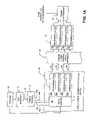
- FIG. 1is a block diagram of a downstream path of a transmission system
- FIG. 1Ais a block diagram of a downstream path of a transmission system that includes a Transmission Control Protocol (TCP) gateway;
- TCPTransmission Control Protocol
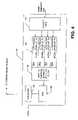
- FIG. 2is a block diagram of an upstream path of a transmission system
- FIG. 3is a block diagram of a demodulator portion of a FastChannel modem
- FIG. 4is a block diagram of a modulator portion of a FastChannel modem
- FIG. 5is a block diagram which illustrates bundling Data Over Cable Standard Interface Specification (DOCSIS) channels via internet protocol (IP) tunneling; and
- DOCSISData Over Cable Standard Interface Specification
- FIG. 6is a block diagram of a demodulator portion of a FastChannel modem.
- a downstream path of a transmission system 10includes a first router 12 coupled to a tunnel source (also referred to as a sending tunnel end-point) 16 through a first signal path 14 (referred to hereinbelow as a FastChannel path).
- Tunnel source 16is coupled to a cable modem termination system (CMTS) 20 through a second signal path 18 here shown as signal paths 18 a – 18 d .
- CMTScable modem termination system
- the tunnel source 16can functionally reside in a separate box upstream of the CMTS 20 as shown in FIG. 1 .
- the tunnel source 16can functionally reside within the CMTS 20 or the router 12 .
- the CMTS 20includes a CMTS router 22 and a plurality of quadrature amplitude modulators (QAMs) 24 a – 24 d generally denoted 24 .
- Router 12is also coupled to the CMTS 20 , and in particular to the CMTS router 22 , via a signal path 26 .
- the purpose of the signal paths 14 and 26will next be described in general overview.
- a packet encapsulation and tunneling procedurecan be used which includes two different IP address spaces associated with IP over cable offerings.
- a first address space(referred to as an L address space) is for existing single-channel users operating in accordance with the Data Over Cable Standard Interface Specification (DOCSIS).
- a second address space(referred to as an F address space) is for FastChannel users (i.e. users of the protocol described herein).
- the router 12is adjacent to and upstream of the CMTS 20 , such that, if a packet having a destination address in the L address space is received, the router 16 directly routes the packet to the CMTS 20 via signal path 26 without passing through the tunneling node 16 .
- Tunnel source 16receives data provided thereto from the router 12 and divides the serialized data stream into a plurality of parallel channels which are fed via the signal path 18 a to the CMTS 20 .
- signals paths 18 b – 18 dare shown in phantom to indicate that the parallel signals are logically separate but can be transmitted on a single physical signal path (e.g. a single wire) such as the signal path 18 a.
- the CMTS router 22Whether fed to the CMTS router 24 via the FastChannel path 14 or via the legacy path 26 , the CMTS router 22 provides each of the signals to one of a plurality of modulators 24 a – 24 d generally denoted 24 .
- the modulators 24are preferably provided as quadrature amplitude modulators (QAMs). It should be appreciated, however, that in other embodiments it may be desirable or even necessary to utilize other types of modulators including but not limited to quadrature phase-shift keyed (QPSK), spread spectrum, orthogonal-frequency-division multiplexed (OFDM) and code-division multiple-access (CDMA) modulators.
- QPSKquadrature phase-shift keyed
- OFDMorthogonal-frequency-division multiplexed
- CDMAcode-division multiple-access
- a plurality of parallel channels 28 a – 28 dare formed via the CMTS router 22 and the QAM modulators 24 a – 24 d .
- Each of the modulators 24modulates the signal fed thereto and provides the so-modulated signal to a corresponding one of a plurality of radio frequency (RF) channels in a hybrid fiber coaxial (HFC) network 30 .
- RFradio frequency
- HFC 30corresponds to a cable network utilizing a combination of optical fibers and coaxial cables of the types known to be used in the cable television industry for transmission of television signals.
- HFC 30could be replaced with a wireless system, wherein signals are transmitted over the air, typically using the MMDS band, rather than over HFC plant as described for example, in AT&T Labs broadband fixed wireless field experiment, Byoung-Jo Kim; Shankaranarayanan, N. K.; Henry, P. S.; Schlosser, K.; Fong, T. K. IEEE Communications Magazine, Volume: 37 Issue: 10, Oct. 1999 page(s) 56–62.
- Signalsare provided via the parallel channels and the HFC 30 to a corresponding plurality of demodulators 32 here provided as quadrature amplitude modulation (QAM) demodulators 32 .
- the demodulators 32provide demodulated signals to a tunnel destination 34 (also referred to as a destination end-point) which receives the demodulated tunnel source signals and re-serializes the data.
- a tunnel destination 34also referred to as a destination end-point
- the tunnel destination 34is coupled to personal computers (PCs) or other devices of a user or subscriber, typically via a 100baseT local area network (LAN) connection.
- PCspersonal computers
- LANlocal area network
- each of the channels 28 a – 28 dis provided as an RF channel between the send and receive sites and virtual links are established over each of the RF channels. Packets are distributed over these virtual links in a controlled fashion. Thus, virtual links can be established over each RF channel between send and receive sites.
- the term “virtual link”means a logical connection between a sender and a receiver, where both ends are addressable via some type of address. Data is sent via packets or link layer frames, which contain the sending and receiving address (as well as other information) in a packet or frame header. Many virtual links can share the same physical link.
- the virtual linksare established via a MAC-layer process. Those of ordinary skill in the art will appreciate that the MAC layer is also known as an OSI layer 2 .
- the virtual linksare provided via an Internet Protocol IP within IP encapsulation or tunneling process.
- IPInternet Protocol
- tunneling processesincluding but not limited to IP within User Datagram Protocol (UDP), IP within TCP can also be used.
- IP tunnelingincludes IP over TCP and UDP or any other mechanism by which IP is the inside layer, and IP, TCP or UDP is the outside layer.
- IP encapsulation within IPand IP tunneling are used.
- This techniqueallows an incoming IP packet to be placed in the payload field of an encapsulation packet having source and destination address headers which point to the respective end-points of the tunnel.
- the encapsulation headeris stripped off, and the original packet is forwarded by the tunnel end-point toward the original destination.
- the sending tunnel end-pointcan functionally reside in a separate box upstream of the CMTS.
- the receiving tunnel end-pointwill reside in a box, which terminates the N cable modem MAC interfaces.
- Each cable modem interfaceis assigned an IP address and multiple tunnels are created from the sending end-point to the IP address endpoints of each cable modem.
- load balancingincludes but is not limited to adjustment of system characteristics to adjust and fix congestion situations or to avoid them.
- Load balancingcan be achieved via monitoring or scheduling techniques. When using a monitoring technique, system characteristics are adjusted once a particular condition or state, such as an overload condition, is detected. When using a scheduling technique, on the other hand, system characteristics (e.g. quality of service-QOS) are monitored and system adjustments are made prior to an overload condition occurring.
- monitoring techniquesystem characteristics are adjusted once a particular condition or state, such as an overload condition, is detected.
- scheduling techniqueon the other hand, system characteristics (e.g. quality of service-QOS) are monitored and system adjustments are made prior to an overload condition occurring.
- Each virtual link(both upstream and downstream) may be shared by multiple data flows, where data flows might have the same or different sources and destinations. Scheduling policies provide QoS to these flows, primarily bandwidth and delay. Flows carrying interactive applications (including but not limited to voice calls and video conferencing) have stringent delay requirements that should be fulfilled. For the applied scheduling policy and existing flows with their QoS requirements, resources will be assigned to a new flow with the specified QoS requirements if they are available.
- DOCSISdefines the admission control procedure: how the resource is requested by the higher layer protocols, and how the information about the resource availability is stored in CMTS. DOCSIS also defines QoS parameters that applications may specify when requesting the resource. In accordance with the present technique, the resource will be assigned to users that utilize multiple virtual links with the higher probability. The QoS capabilities of IP that is likely to carry data in the access network in question are currently under development.
- each of the plurality of RF channelsare adjacent in frequency while in other embodiments, each of the plurality of RF channels are not adjacent in frequency. Allowing the channels to be not adjacent in frequency permits greater flexibility when interworking with an existing cable plant which may already contain a high occupancy of video channels.
- Using adjacent channelsmay simplify the modem design, as a single down-converter and digital-to-analog converter may be used. The adjacent channels can then be separated using digital techniques.
- bit-levelthe bit-level
- MACmedia access control
- the MAC frame level techniqueinvolves distributing the MAC transmission frames across the multiple channels, and recombining the frames into a single stream at the modem.
- the IP packet level techniqueinvolves distributing the packets across the multiple channels, and recombining the packets into a single stream at the modem. The differences between these two alternatives are that in the frame-level case, a channel number/frequency band must be mapped to a different MAC destination address, while in the packet level case a channel number/frequency band must be mapped to a different IP address.
- the frame level methodintegrates the recombining of packets with the cable modem. In contrast, the packet level method allows the tunnel end-point to be placed “outside” a DOCSIS cable modem.
- the FastChannel modemcould be constructed from multiple DOCSIS cable modems and a tunneling end-point.
- the distribution of packetsis most natural inside the CMTS with the frame method, and may take place outside the CMTS with the packet method.
- the frame level methodwill allow relatively tight integration into the CMTS and modem components and therefore may be most cost-effective in the long run.
- the FastChannel modemscould not be created by simply combining together several current DOCSIS cable modems.
- the packet level methodwhile possibly not optimal in the long run, allows use of existing cable modems and CMTS without requiring modification to the CMTS.
- the packet level methodallows the tunneling end-points to be separate from the CMTS and DOCSIS cable modems. Furthermore, a tunneling end-point that is separate from the CMTS can serve multiple CMTS. This may make it easier to add capacity to a system, as additional DOCSIS channels could be added, and served with the FastChannel protocol, without needing to upgrade the previously installed CMTS.
- CMTS 20maintains N separate output queues, one for each RF channel.
- FIG. 1four queues 28 a – 28 d are shown. Frames are thus placed into one of the four output channels as they arrive.
- an alternative queuing disciplinecomprises insertion of frames into the shortest queue, where the “shortest” metric should represent frame service time. It is possible to estimate the frame service time based on an appropriate combination of byte and packet counts in the output buffer.
- a frame “serialization” functionis required, which simply plays out received frames serially into the output in the MAC-level driver, in the order in which they were received.
- ordershould be measured as the time at which the first byte of the frame is received rather than the last byte, in order to further reduce the possibility of frame mis-ordering.
- IP encapsulation within IP/IP tunnelingcan be used.
- This techniqueallows an incoming IP packet to be placed in the payload field of an encapsulation packet, having source and destination address headers that point to the respective end-points of the tunnel.
- the encapsulation headeris stripped off, and the original packet is forwarded by the tunnel end-point toward the original destination.
- the proposed use of this techniqueis described in detail below in conjunction with FIG. 5 .
- the tunnel destination 34can reside in a box, which terminates the N cable modem MAC interfaces.
- Each cable modem interfaceis assigned an IP address, and multiple tunnels are created from the sending end-point (e.g. tunnel source 16 ), to the IP address endpoints of each cable modem.
- a queue-scheduling algorithmis employed at the end point of the sending tunnel 16 , which uniformly distributes the IP packets over each tunnel.
- IP-based approachthe tunnel does not have access to the output buffer state on the CMTS itself, only on the tunnel machine.
- the tunnel buffer statemay not be the same as the CMTS buffer state. If it turns out that packet sequence problems may arise because of this difference, it may be necessary to add a sequence number field to the encapsulation header.
- the downstream transmission rate of TCPis limited by the speed at which an acknowledgement is received from the upstream module.
- a known transmission control protocol (TCP) gateway 13is interposed between the router 12 and the tunnel source 16 .
- TCP gatewaytransparently terminates the TCP connection, provides acknowledgements back to the sending node, prior to them being received by the TCP receiver. The sender is therefore able to grow its transmission window faster and send data faster than it would otherwise be able to.
- an upstream path of a transmission systemsuch as the transmission system 10 described above in conjunction with FIGS. 1 and 1A includes subscriber systems 36 which transmit signals through IP tunnel sources 38 .
- the tunnel sources 38form a plurality of channels 40 a – 40 d each of which are coupled to one of a plurality of upstream modulators 42 a – 42 d which in turn are coupled to an HFC 44 .
- the upstream plurality of parallel channelsare coupled to a CMTS 46 and in particular, the parallel channels are coupled to corresponding ones of a plurality of demodulators 48 a - 48 d , generally denoted 48 .
- the upstream demodulatorsprovide the signal to a CMTS router 50 which in turn provides the signals to an IP tunnel destination 52 and subsequently to a router 54 .
- signalscan be transmitted in the upstream direction within the transmission system.
- the MAC frame level technique and the (IP) packet level technique for utilizing the bandwidth of the parallel channels discussed above in the downstream casecan also be used in the upstream case.
- a demodulator 60 of the type which may be used in a modem coupled to receive signals from a FastChannel signal pathincludes a tuner 62 provided from a downconverter module 64 having a local oscillator (LO) 66 coupled thereto.
- the downconverter module 64receives RF signals at a first port thereof and an LO signal at a second port thereof and provides an output signal having a frequency equal to the difference between the frequencies of the RF signal and the LO signal.
- demodulator embodiment shown in FIG. 3requires that the parallel channels be adjacent to one another. It should also be understood that other demodulator embodiments may not require that the parallel channels be adjacent one another.
- the tuner, band pass filter and ADCcan be provided having performance characteristics that are similar or in some instances even identical to those used in serial modems.
- the downconverter module output signalis provided to a filter 68 having a band pass filter characteristic.
- the so-filtered signalis then fed to an input port of an analog to digital converter (ADC) 70 , which receives the analog signal at an input thereof and provides at an output port thereof a stream of bits which represents the analog signal fed thereto.
- ADCanalog to digital converter
- the ADC 70is followed by processors 72 a – 72 d generally denoted 72 each of which simulates a filter having a band pass filter characteristic.
- processors 72 a – 72 dcorrespond to digital filters.
- the filtersare provided having a 5 megahertz (MHz) bandwidth.
- Each band-pass filter 72 a – 72 dis followed by processors 74 a – 74 d , generally denoted 74 , which perform a demodulation process.
- processors 74 a – 74 dperform 5 Msymbols/sec QAM demodulation. It should be understood that although multiple processors are shown, this does not mean that multiple chips would be required. It should also be understood that the processor requirements of this modem may be easier to meet than those of a demodulator used in a serial modem, as a band-pass filter is rather simple computation, and the symbol rate of each QAM channel is lower. Thus, a single integrated circuit or “chip” can contain multiple demodulators and digital filters.
- the demodulators 74provide the filtered, demodulated signal to a serializer 76 .
- Serializer 76receives the signals in parallel from the demodulators 74 and re-serializes the packets to provide a serial signal at an output port 76 a.
- a modulator portion 80 of a modemincludes a packet inverse multiplexor (mux) 82 adapted to receive signals from a user.
- the inverse mux 82is coupled to a home 100 base T LAN.
- the inverse mux 82provides signals to a plurality of upstream modulators 84 a – 84 d , generally denoted 84 .
- Each of the modulators 84 a - 84 dmodulates the signals fed thereto at a different frequency, designated F 1 –F 4 in FIG. 4 .
- the modulators 84provide signals to a digital signal processor DSP 86 which combines the signals at frequencies F 1 –F 4 .
- the DSP 86provides a stream of bits to a digital to analog converter (DAC) 88 which receives the bit stream and generates a corresponding analog signal at an output port thereof.
- the analog signalis fed from the DAC 88 to a diplexor 90 .
- Diplexor 90is adapted to provide signals to one of the coax signal port and a downstream signal port.
- the diplexer 90sends the upstream signals, which are within a first frequency band (typically 5–42 MHz) to the headend via the HFC infrastructure. It simultaneously sends the downstream signals within a second frequency band (typically this frequency band begins at 55 MHz and ends somewhere between 500 MHz and 900 MHz) to the demodulator portion of the FastChannel modem.
- a system for processing data in a series of parallel channelsincludes a router 92 coupled via a signal path 94 to a tunnel source 96 and via a signal path 98 to a CMTS 100 .
- the CMTSis coupled via a plurality of cable channels 102 a – 102 N to a like plurality of tunnel destinations 104 a – 104 N generally denoted 104 on a machine 105 .
- the tunnel destinationsare coupled to a processor or computer 106 via a standard network interface such as an Ethernet interface.
- a Personal Computer (PC) 108having an address E.
- PC 108represents a conventional DOCSIS user. This user simply uses one of the channels 102 a – 102 N.
- the DOCSIS useris coupled to channel 102 N.
- This conventional userplays no part in the FastChannel arrangement. It merely illustrates the co-existence of the FastChannel channel system and protocol with a conventional DOCSIS system and protocol.
- Tunnel 96is connected to the CMTS via an interface having an IP address designated as T 1 .
- the packet 110originated at a source with address S (identified with reference designator 110 a in FIG. 5 ) and is destined to the PC 106 having an address D (identified with reference designator 110 b in FIG. 5 ).
- address Dis an element of address space F (i.e. a FastChannel address space).
- the tunnel source 96 having the address T 1encapsulates the packet by creating a new packet 112 , placing the original packet 110 in the payload field of the new packet 112 , and adding a new packet header 114 .
- the source addressis T 1 (identified with reference designator 112 a in FIG. 5 ) and destination address is one of a, b, . . . , n, (identified with reference designator 112 b in FIG. 5 ) which are separate IP interfaces on tunnel destination 104 .
- CMTS 100is configured such that the subnetwork address of which address a is a member, is mapped onto cable channel 102 a;
- the encapsulated packets 114are then routed via the appropriate tunnel to the tunnel destination 104 .
- the encapsulation headersare removed to again provide packet 110 , and the packets are forwarded in their original order to the destination, which in this case is the PC 106 .
- the address allocation method of the present inventionallows legacy DOCSIS users to share channels with FastChannel users.
- a PC 108 with address E(where E is in the L address space) is able to receive data addressed to it, while sharing channel 102 N with the FastChannel-attached PC 106 with address D.
- an alternate embodiment of a demodulator portion 120 of a FastChannel modemincludes a plurality of tuners 122 a – 122 d .
- Each of the tunersare provided from a respective one of a plurality of down converter modules 124 a – 124 d having a respective one of a plurality of local oscillators (LO) 126 a – 126 d coupled thereto.
- LOlocal oscillators
- the down converter module 124 areceives RF signals at a first port thereof and an LO signal at a second port thereof and provides an output signal having a frequency equal to the difference between the frequencies of the RF signal and the LO signal.
- the output signals from the tuners 122 a – 122 dare provided to respective ones of filters 128 a – 128 d with each of the filters having a band pass filter characteristic.
- the filtered signalsare then fed to respective ones of a plurality of analog to digital converters (ADC) 130 a – 130 d .
- ADCs 130 a – 130 dreceive the analog signals at inputs thereof and provide at outputs thereof a stream of bits which represents the analog signal fed to each ADC.
- the ADCs 130 a – 130 dare followed by processors 132 a – 132 d each of which perform a demodulation process, In one embodiment, processors 132 a – 132 d perform 5 Msymbols/sec QAM demodulation. It should be understood that although multiple processors are shown, this does not mean that multiple integrated circuits would be required.
- the demodulators 132 a – 132 dprovide the filtered, demodulated signal to a serializer 134 .
- Serializer 134receives the signals in parallel from the demodulators 132 a – 132 d and re-serializes the packets to provide a serial signal at an output port of the serializer 134 .
- the demodulator 120illustrates one method for receiving FastChannel data when parallel transmission is used. It should be appreciated that in demodulator 120 multiple demodulators 132 a – 132 d are used, and the output is combined in the serializer 134 . The serializer would multiplex the received packets or frames. Such an approach should not require extensive buffering, since the headend controls the peak rate to each user. Such a demodulator can be readily implemented using currently available commercial components. An additional benefit of this approach is that any RF channels can be used, they need not be adjacent to one another. One drawback to this design is that it may be relatively expensive compared with an integrated, multiple-channel demodulator since it has more components, including multiple RF tuners and bandpass filters.
Landscapes
- Engineering & Computer Science (AREA)
- Computer Networks & Wireless Communication (AREA)
- Signal Processing (AREA)
- Computer Security & Cryptography (AREA)
- Power Engineering (AREA)
- Two-Way Televisions, Distribution Of Moving Picture Or The Like (AREA)
- Data Exchanges In Wide-Area Networks (AREA)
Abstract
Description
Claims (29)
Priority Applications (3)
| Application Number | Priority Date | Filing Date | Title |
|---|---|---|---|
| US09/924,639US6993353B2 (en) | 2001-03-14 | 2001-08-08 | Cable data service method |
| CA2614957ACA2614957C (en) | 2001-03-14 | 2002-02-19 | Cable data service method |
| CA002372415ACA2372415C (en) | 2001-03-14 | 2002-02-19 | Cable data service method |
Applications Claiming Priority (2)
| Application Number | Priority Date | Filing Date | Title |
|---|---|---|---|
| US27566501P | 2001-03-14 | 2001-03-14 | |
| US09/924,639US6993353B2 (en) | 2001-03-14 | 2001-08-08 | Cable data service method |
Publications (2)
| Publication Number | Publication Date |
|---|---|
| US20020132629A1 US20020132629A1 (en) | 2002-09-19 |
| US6993353B2true US6993353B2 (en) | 2006-01-31 |
Family
ID=26957529
Family Applications (1)
| Application Number | Title | Priority Date | Filing Date |
|---|---|---|---|
| US09/924,639Expired - LifetimeUS6993353B2 (en) | 2001-03-14 | 2001-08-08 | Cable data service method |
Country Status (1)
| Country | Link |
|---|---|
| US (1) | US6993353B2 (en) |
Cited By (39)
| Publication number | Priority date | Publication date | Assignee | Title |
|---|---|---|---|---|
| US20040163129A1 (en)* | 2003-02-04 | 2004-08-19 | Cisco Technology, Inc. | Wideband cable system |
| US20050265398A1 (en)* | 2004-05-25 | 2005-12-01 | Cisco Technology, Inc. | Tunneling scheme for transporting information over a cable network |
| US20050265394A1 (en)* | 2004-05-25 | 2005-12-01 | Chapman John T | Wideband cable modem with narrowband circuitry |
| US20050265338A1 (en)* | 2001-06-27 | 2005-12-01 | Chapman John T | Downstream remote physical interface for modular cable modem termination system |
| US20050265392A1 (en)* | 2004-05-25 | 2005-12-01 | Fox David B | Wideband cable downstream protocol |
| US20050265261A1 (en)* | 2004-05-25 | 2005-12-01 | Droms Ralph E | Neighbor discovery in cable networks |
| US20050265309A1 (en)* | 2004-05-25 | 2005-12-01 | Harshavardhan Parandekar | Local area network services in a cable modem network |
| US20050265397A1 (en)* | 2001-06-27 | 2005-12-01 | Cisco Technology, Inc. | Upstream physical interface for modular cable modem termination system |
| US20060002294A1 (en)* | 2004-05-25 | 2006-01-05 | Chapman John T | Wideband provisioning |
| US20080298277A1 (en)* | 2004-05-25 | 2008-12-04 | Cisco Technology, Inc. | Neighbor discovery proxy with distributed packet inspection scheme |
| US20090185574A1 (en)* | 2004-05-25 | 2009-07-23 | Cisco Technology, Inc. | Timing system for modular cable modem termination system |
| US20090213935A1 (en)* | 2002-12-10 | 2009-08-27 | Van Der Laan Roger | System and Method For Compressing Video By Allocating Bits To Image Tiles Based On Detected Intraframe Motion Or Scene Complexity |
| US20090225863A1 (en)* | 2002-12-10 | 2009-09-10 | Perlman Stephen G | Video Compression System and Method for Reducing the Effects of Packet Loss Over a Communciation Channel |
| US20090225220A1 (en)* | 2002-12-10 | 2009-09-10 | Van Der Laan Roger | System and Method For Compressing Video By Adjusting Tile Size Based On Detected Intraframe Motion Or Scene Complexity |
| US20090238199A1 (en)* | 2004-05-25 | 2009-09-24 | Cisco Technology, Inc. | Wideband upstream protocol |
| US20090290543A1 (en)* | 2001-03-14 | 2009-11-26 | At&T Intellectual Property I, L.P. | Transmit and Receive Method for a Data Service |
| US7630361B2 (en) | 2005-05-20 | 2009-12-08 | Cisco Technology, Inc. | Method and apparatus for using data-over-cable applications and services in non-cable environments |
| US20100166066A1 (en)* | 2002-12-10 | 2010-07-01 | Steve Perlman | System and Method for Video Compression Using Feedback Including Data Related to the Successful Receipt of Video Content |
| US20100166064A1 (en)* | 2002-12-10 | 2010-07-01 | Perlman Steve G | System and Method for Utilizing Forward Error Correction with Video Compression |
| US20100166063A1 (en)* | 2002-12-10 | 2010-07-01 | Perlman Steve G | System and method for compressing video frames or portions thereof based on feedback information from a client device |
| US20100167816A1 (en)* | 2002-12-10 | 2010-07-01 | Perlman Stephen G | System and Method for Multi-Stream Video Compression |
| US20100226390A1 (en)* | 2009-03-06 | 2010-09-09 | Cisco Techology, Inc. | Dynamically and fairly allocating rf channel bandwidth in a wideband cable system |
| US7924798B1 (en)* | 2002-11-27 | 2011-04-12 | Sprint Spectrum L.P. | Method for transmitting data in a wireless telecommunications network using multiple data channels |
| US8160098B1 (en) | 2009-01-14 | 2012-04-17 | Cisco Technology, Inc. | Dynamically allocating channel bandwidth between interfaces |
| US20120303757A1 (en)* | 2008-03-27 | 2012-11-29 | Broadcom Corporation | Channel Frequency Reuse for Narrow Beam Video Streaming Based Upon Mobile Terminal Location Information |
| US8711923B2 (en) | 2002-12-10 | 2014-04-29 | Ol2, Inc. | System and method for selecting a video encoding format based on feedback data |
| US8964830B2 (en) | 2002-12-10 | 2015-02-24 | Ol2, Inc. | System and method for multi-stream video compression using multiple encoding formats |
| US9061207B2 (en) | 2002-12-10 | 2015-06-23 | Sony Computer Entertainment America Llc | Temporary decoder apparatus and method |
| US9084936B2 (en) | 2002-12-10 | 2015-07-21 | Sony Computer Entertainment America Llc | System and method for protecting certain types of multimedia data transmitted over a communication channel |
| US9138644B2 (en) | 2002-12-10 | 2015-09-22 | Sony Computer Entertainment America Llc | System and method for accelerated machine switching |
| US9168457B2 (en) | 2010-09-14 | 2015-10-27 | Sony Computer Entertainment America Llc | System and method for retaining system state |
| US9192859B2 (en) | 2002-12-10 | 2015-11-24 | Sony Computer Entertainment America Llc | System and method for compressing video based on latency measurements and other feedback |
| US9446305B2 (en) | 2002-12-10 | 2016-09-20 | Sony Interactive Entertainment America Llc | System and method for improving the graphics performance of hosted applications |
| US9723267B2 (en) | 2004-12-15 | 2017-08-01 | Time Warner Cable Enterprises Llc | Method and apparatus for wideband distribution of content |
| US9800909B2 (en) | 2004-04-05 | 2017-10-24 | Avago Technologies General Ip (Singapore) Pte. Ltd. | Method and apparatus for downloading content using channel bonding |
| US10200731B2 (en) | 2010-09-03 | 2019-02-05 | Time Warner Cable Enterprises Llc | Digital domain content processing and distribution apparatus and methods |
| US10201760B2 (en) | 2002-12-10 | 2019-02-12 | Sony Interactive Entertainment America Llc | System and method for compressing video based on detected intraframe motion |
| US10411939B2 (en) | 2010-05-27 | 2019-09-10 | Time Warner Cable Enterprises Llc | Digital domain content processing and distribution apparatus and methods |
| US10432990B2 (en) | 2001-09-20 | 2019-10-01 | Time Warner Cable Enterprises Llc | Apparatus and methods for carrier allocation in a communications network |
Families Citing this family (12)
| Publication number | Priority date | Publication date | Assignee | Title |
|---|---|---|---|---|
| CA2416659C (en)* | 2002-01-22 | 2007-01-16 | Nippon Telegraph And Telephone Corporation | Capacity variable link apparatus and capacity variable link setting method |
| US7023871B2 (en)* | 2003-05-28 | 2006-04-04 | Terayon Communication Systems, Inc. | Wideband DOCSIS on catv systems using port-trunking |
| US9722850B2 (en)* | 2004-08-09 | 2017-08-01 | Arris Enterprises Llc | Method and system for transforming video streams using a multi-channel flow-bonded traffic stream |
| WO2006020559A2 (en)* | 2004-08-09 | 2006-02-23 | Arris International, Inc. | Very high speed cable modem for increasing bandwidth |
| CN101027862B (en)* | 2004-10-29 | 2011-06-08 | 美国博通公司 | Multi-channel communication with hierarchical communication traffic |
| US7865610B2 (en)* | 2007-03-12 | 2011-01-04 | Nautel Limited | Point to multipoint reliable protocol for synchronous streaming data in a lossy IP network |
| US9413632B2 (en) | 2007-10-05 | 2016-08-09 | Entropic Communications, Llc | Method for extended rate/range communication over a communication network |
| TW200926809A (en)* | 2007-10-05 | 2009-06-16 | Nxp Bv | Method, system and apparatus for extended rate/range communication over a communication network |
| US8904022B1 (en)* | 2007-11-05 | 2014-12-02 | Ignite Technologies, Inc. | Split streaming system and method |
| US9660792B2 (en)* | 2012-06-30 | 2017-05-23 | Cable Television Laboratories, Inc. | Multi-carrier transmission |
| US20140010315A1 (en)* | 2012-07-06 | 2014-01-09 | Curtis Ling | Method and system for dynamic cable modem termination system (cmts) port to demodulator assignment in a cable headend (he) |
| KR102144509B1 (en)* | 2014-03-06 | 2020-08-14 | 삼성전자주식회사 | Proximity communication method and apparatus |
Citations (4)
| Publication number | Priority date | Publication date | Assignee | Title |
|---|---|---|---|---|
| US5778174A (en) | 1996-12-10 | 1998-07-07 | U S West, Inc. | Method and system for providing secured access to a server connected to a private computer network |
| US5943604A (en)* | 1997-10-31 | 1999-08-24 | Cisco Technology, Inc. | Echo device method for locating upstream ingress noise gaps at cable television head ends |
| US6055236A (en) | 1998-03-05 | 2000-04-25 | 3Com Corporation | Method and system for locating network services with distributed network address translation |
| US6230326B1 (en) | 1998-07-30 | 2001-05-08 | Nortel Networks Limited | Method and apparatus for initialization of a cable modem |
- 2001
- 2001-08-08USUS09/924,639patent/US6993353B2/ennot_activeExpired - Lifetime
Patent Citations (4)
| Publication number | Priority date | Publication date | Assignee | Title |
|---|---|---|---|---|
| US5778174A (en) | 1996-12-10 | 1998-07-07 | U S West, Inc. | Method and system for providing secured access to a server connected to a private computer network |
| US5943604A (en)* | 1997-10-31 | 1999-08-24 | Cisco Technology, Inc. | Echo device method for locating upstream ingress noise gaps at cable television head ends |
| US6055236A (en) | 1998-03-05 | 2000-04-25 | 3Com Corporation | Method and system for locating network services with distributed network address translation |
| US6230326B1 (en) | 1998-07-30 | 2001-05-08 | Nortel Networks Limited | Method and apparatus for initialization of a cable modem |
Cited By (84)
| Publication number | Priority date | Publication date | Assignee | Title |
|---|---|---|---|---|
| US7990977B2 (en)* | 2001-03-14 | 2011-08-02 | At&T Intellectual Property I, L.P. | Method, system, and device for sending data in a cable data service |
| US20100208751A1 (en)* | 2001-03-14 | 2010-08-19 | At&T Intellectual Property I, L.P. | Method, System, and Device for Sending Data in a Cable Data Service |
| US20100265942A1 (en)* | 2001-03-14 | 2010-10-21 | At&T Intellectual Property I, L.P. | Receive Device for a Cable Data Service |
| US20090290543A1 (en)* | 2001-03-14 | 2009-11-26 | At&T Intellectual Property I, L.P. | Transmit and Receive Method for a Data Service |
| US10009190B2 (en) | 2001-03-14 | 2018-06-26 | At&T Intellectual Property Ii, L.P. | Data service including channel group |
| US8855147B2 (en) | 2001-03-14 | 2014-10-07 | At&T Intellectual Property Ii, L.P. | Devices and methods to communicate data streams |
| US8000331B2 (en)* | 2001-03-14 | 2011-08-16 | At&T Intellectual Property Ii, L.P. | Receive device for a cable data service |
| US20050265338A1 (en)* | 2001-06-27 | 2005-12-01 | Chapman John T | Downstream remote physical interface for modular cable modem termination system |
| US20050265397A1 (en)* | 2001-06-27 | 2005-12-01 | Cisco Technology, Inc. | Upstream physical interface for modular cable modem termination system |
| US20070195824A9 (en)* | 2001-06-27 | 2007-08-23 | Cisco Technology, Inc. | Upstream physical interface for modular cable modem termination system |
| US7688828B2 (en) | 2001-06-27 | 2010-03-30 | Cisco Technology, Inc. | Downstream remote physical interface for modular cable modem termination system |
| US7639617B2 (en) | 2001-06-27 | 2009-12-29 | Cisco Technology, Inc. | Upstream physical interface for modular cable modem termination system |
| US10432990B2 (en) | 2001-09-20 | 2019-10-01 | Time Warner Cable Enterprises Llc | Apparatus and methods for carrier allocation in a communications network |
| US11303944B2 (en) | 2001-09-20 | 2022-04-12 | Time Warner Cable Enterprises Llc | Apparatus and methods for carrier allocation in a communications network |
| US7924798B1 (en)* | 2002-11-27 | 2011-04-12 | Sprint Spectrum L.P. | Method for transmitting data in a wireless telecommunications network using multiple data channels |
| US9155962B2 (en) | 2002-12-10 | 2015-10-13 | Sony Computer Entertainment America Llc | System and method for compressing video by allocating bits to image tiles based on detected intraframe motion or scene complexity |
| US9314691B2 (en) | 2002-12-10 | 2016-04-19 | Sony Computer Entertainment America Llc | System and method for compressing video frames or portions thereof based on feedback information from a client device |
| US20090225828A1 (en)* | 2002-12-10 | 2009-09-10 | Perlman Stephen G | Video Compression System and Method for Compensating for Bandwidth Limitations of a Communication Channel |
| US20090225220A1 (en)* | 2002-12-10 | 2009-09-10 | Van Der Laan Roger | System and Method For Compressing Video By Adjusting Tile Size Based On Detected Intraframe Motion Or Scene Complexity |
| US10201760B2 (en) | 2002-12-10 | 2019-02-12 | Sony Interactive Entertainment America Llc | System and method for compressing video based on detected intraframe motion |
| US20090220001A1 (en)* | 2002-12-10 | 2009-09-03 | Van Der Laan Roger | Tile-Based System and method For Compressing Video |
| US10130891B2 (en) | 2002-12-10 | 2018-11-20 | Sony Interactive Entertainment America Llc | Video compression system and method for compensating for bandwidth limitations of a communication channel |
| US20090215540A1 (en)* | 2002-12-10 | 2009-08-27 | Perlman Stephen G | System and Method for Intelligently Allocating Client Requests to Server Centers |
| US9446305B2 (en) | 2002-12-10 | 2016-09-20 | Sony Interactive Entertainment America Llc | System and method for improving the graphics performance of hosted applications |
| US20090213927A1 (en)* | 2002-12-10 | 2009-08-27 | Perlman Stephen G | System and Method for Compressing Video Based on Detected Data Rate of a Communication Channel |
| US9420283B2 (en) | 2002-12-10 | 2016-08-16 | Sony Interactive Entertainment America Llc | System and method for selecting a video encoding format based on feedback data |
| US20100166066A1 (en)* | 2002-12-10 | 2010-07-01 | Steve Perlman | System and Method for Video Compression Using Feedback Including Data Related to the Successful Receipt of Video Content |
| US20100166064A1 (en)* | 2002-12-10 | 2010-07-01 | Perlman Steve G | System and Method for Utilizing Forward Error Correction with Video Compression |
| US20100166063A1 (en)* | 2002-12-10 | 2010-07-01 | Perlman Steve G | System and method for compressing video frames or portions thereof based on feedback information from a client device |
| US20100167816A1 (en)* | 2002-12-10 | 2010-07-01 | Perlman Stephen G | System and Method for Multi-Stream Video Compression |
| US20090213935A1 (en)* | 2002-12-10 | 2009-08-27 | Van Der Laan Roger | System and Method For Compressing Video By Allocating Bits To Image Tiles Based On Detected Intraframe Motion Or Scene Complexity |
| US20090225863A1 (en)* | 2002-12-10 | 2009-09-10 | Perlman Stephen G | Video Compression System and Method for Reducing the Effects of Packet Loss Over a Communciation Channel |
| US9272209B2 (en) | 2002-12-10 | 2016-03-01 | Sony Computer Entertainment America Llc | Streaming interactive video client apparatus |
| US9192859B2 (en) | 2002-12-10 | 2015-11-24 | Sony Computer Entertainment America Llc | System and method for compressing video based on latency measurements and other feedback |
| US9138644B2 (en) | 2002-12-10 | 2015-09-22 | Sony Computer Entertainment America Llc | System and method for accelerated machine switching |
| US9084936B2 (en) | 2002-12-10 | 2015-07-21 | Sony Computer Entertainment America Llc | System and method for protecting certain types of multimedia data transmitted over a communication channel |
| US9077991B2 (en) | 2002-12-10 | 2015-07-07 | Sony Computer Entertainment America Llc | System and method for utilizing forward error correction with video compression |
| US9061207B2 (en) | 2002-12-10 | 2015-06-23 | Sony Computer Entertainment America Llc | Temporary decoder apparatus and method |
| US8964830B2 (en) | 2002-12-10 | 2015-02-24 | Ol2, Inc. | System and method for multi-stream video compression using multiple encoding formats |
| US8953675B2 (en) | 2002-12-10 | 2015-02-10 | Ol2, Inc. | Tile-based system and method for compressing video |
| US8881215B2 (en) | 2002-12-10 | 2014-11-04 | Ol2, Inc. | System and method for compressing video based on detected data rate of a communication channel |
| US8769594B2 (en)* | 2002-12-10 | 2014-07-01 | Ol2, Inc. | Video compression system and method for reducing the effects of packet loss over a communication channel |
| US8711923B2 (en) | 2002-12-10 | 2014-04-29 | Ol2, Inc. | System and method for selecting a video encoding format based on feedback data |
| US8606942B2 (en) | 2002-12-10 | 2013-12-10 | Ol2, Inc. | System and method for intelligently allocating client requests to server centers |
| US8526490B2 (en) | 2002-12-10 | 2013-09-03 | Ol2, Inc. | System and method for video compression using feedback including data related to the successful receipt of video content |
| US8366552B2 (en) | 2002-12-10 | 2013-02-05 | Ol2, Inc. | System and method for multi-stream video compression |
| US20110051753A1 (en)* | 2003-02-04 | 2011-03-03 | Cisco Technology, Inc. | Wideband cable system |
| US8457156B2 (en) | 2003-02-04 | 2013-06-04 | Cisco Technology, Inc. | Wideband cable system |
| US7782898B2 (en) | 2003-02-04 | 2010-08-24 | Cisco Technology, Inc. | Wideband cable system |
| US20040163129A1 (en)* | 2003-02-04 | 2004-08-19 | Cisco Technology, Inc. | Wideband cable system |
| US9800909B2 (en) | 2004-04-05 | 2017-10-24 | Avago Technologies General Ip (Singapore) Pte. Ltd. | Method and apparatus for downloading content using channel bonding |
| US8102854B2 (en) | 2004-05-25 | 2012-01-24 | Cisco Technology, Inc. | Neighbor discovery proxy with distributed packet inspection scheme |
| US20090185574A1 (en)* | 2004-05-25 | 2009-07-23 | Cisco Technology, Inc. | Timing system for modular cable modem termination system |
| US20090238199A1 (en)* | 2004-05-25 | 2009-09-24 | Cisco Technology, Inc. | Wideband upstream protocol |
| US20050265261A1 (en)* | 2004-05-25 | 2005-12-01 | Droms Ralph E | Neighbor discovery in cable networks |
| US20050265394A1 (en)* | 2004-05-25 | 2005-12-01 | Chapman John T | Wideband cable modem with narrowband circuitry |
| US20050265309A1 (en)* | 2004-05-25 | 2005-12-01 | Harshavardhan Parandekar | Local area network services in a cable modem network |
| US20060002294A1 (en)* | 2004-05-25 | 2006-01-05 | Chapman John T | Wideband provisioning |
| US20080298277A1 (en)* | 2004-05-25 | 2008-12-04 | Cisco Technology, Inc. | Neighbor discovery proxy with distributed packet inspection scheme |
| US8160093B2 (en) | 2004-05-25 | 2012-04-17 | Cisco Technology, Inc. | Timing system for modular cable modem termination system |
| US7864686B2 (en) | 2004-05-25 | 2011-01-04 | Cisco Technology, Inc. | Tunneling scheme for transporting information over a cable network |
| US7835274B2 (en) | 2004-05-25 | 2010-11-16 | Cisco Technology, Inc. | Wideband provisioning |
| US8149833B2 (en) | 2004-05-25 | 2012-04-03 | Cisco Technology, Inc. | Wideband cable downstream protocol |
| US8553704B2 (en) | 2004-05-25 | 2013-10-08 | Cisco Technology, Inc. | Wideband upstream protocol |
| US20050265392A1 (en)* | 2004-05-25 | 2005-12-01 | Fox David B | Wideband cable downstream protocol |
| US7817553B2 (en) | 2004-05-25 | 2010-10-19 | Cisco Technology, Inc. | Local area network services in a cable modem network |
| US20050265398A1 (en)* | 2004-05-25 | 2005-12-01 | Cisco Technology, Inc. | Tunneling scheme for transporting information over a cable network |
| US7646786B2 (en) | 2004-05-25 | 2010-01-12 | Cisco Technology, Inc. | Neighbor discovery in cable networks |
| US7720101B2 (en) | 2004-05-25 | 2010-05-18 | Cisco Technology, Inc. | Wideband cable modem with narrowband circuitry |
| US9723267B2 (en) | 2004-12-15 | 2017-08-01 | Time Warner Cable Enterprises Llc | Method and apparatus for wideband distribution of content |
| US11509866B2 (en) | 2004-12-15 | 2022-11-22 | Time Warner Cable Enterprises Llc | Method and apparatus for multi-band distribution of digital content |
| US7630361B2 (en) | 2005-05-20 | 2009-12-08 | Cisco Technology, Inc. | Method and apparatus for using data-over-cable applications and services in non-cable environments |
| US8494440B2 (en)* | 2008-03-27 | 2013-07-23 | Broadcom Corporation | Channel frequency reuse for narrow beam video streaming based upon mobile terminal location information |
| US20120303757A1 (en)* | 2008-03-27 | 2012-11-29 | Broadcom Corporation | Channel Frequency Reuse for Narrow Beam Video Streaming Based Upon Mobile Terminal Location Information |
| US8160098B1 (en) | 2009-01-14 | 2012-04-17 | Cisco Technology, Inc. | Dynamically allocating channel bandwidth between interfaces |
| US8861546B2 (en) | 2009-03-06 | 2014-10-14 | Cisco Technology, Inc. | Dynamically and fairly allocating RF channel bandwidth in a wideband cable system |
| US20100226390A1 (en)* | 2009-03-06 | 2010-09-09 | Cisco Techology, Inc. | Dynamically and fairly allocating rf channel bandwidth in a wideband cable system |
| US10411939B2 (en) | 2010-05-27 | 2019-09-10 | Time Warner Cable Enterprises Llc | Digital domain content processing and distribution apparatus and methods |
| US10892932B2 (en) | 2010-05-27 | 2021-01-12 | Time Warner Cable Enterprises Llc | Digital domain content processing and distribution apparatus and methods |
| US10200731B2 (en) | 2010-09-03 | 2019-02-05 | Time Warner Cable Enterprises Llc | Digital domain content processing and distribution apparatus and methods |
| USRE47760E1 (en) | 2010-09-03 | 2019-12-03 | Time Warner Cable Enterprises Llc | Digital domain content processing and distribution apparatus and methods |
| US10681405B2 (en) | 2010-09-03 | 2020-06-09 | Time Warner Cable Enterprises Llc | Digital domain content processing and distribution apparatus and methods |
| US11153622B2 (en) | 2010-09-03 | 2021-10-19 | Time Warner Cable Enterprises Llc | Digital domain content processing and distribution apparatus and methods |
| US9168457B2 (en) | 2010-09-14 | 2015-10-27 | Sony Computer Entertainment America Llc | System and method for retaining system state |
Also Published As
| Publication number | Publication date |
|---|---|
| US20020132629A1 (en) | 2002-09-19 |
Similar Documents
| Publication | Publication Date | Title |
|---|---|---|
| US10965490B2 (en) | Data service including channel group | |
| US6993353B2 (en) | Cable data service method | |
| US20020133618A1 (en) | Tunneling system for a cable data service | |
| US8953445B2 (en) | Hierarchical flow-level multi-channel communication | |
| US7072360B2 (en) | Network architecture for intelligent network elements | |
| US8862732B2 (en) | Methods and devices for regulating traffic on a network | |
| US8462626B2 (en) | System and method for mapping end user identifiers to access device identifiers | |
| US7027394B2 (en) | Broadband system with traffic policing and transmission scheduling | |
| US7146630B2 (en) | Broadband system with intelligent network devices | |
| US7197045B2 (en) | CMTS architecture based on ethernet interface locatable in a fiber node | |
| US20020105965A1 (en) | Broadband system having routing identification based switching | |
| US20020075875A1 (en) | Broadband system with transmission scheduling and flow control | |
| US20020075814A1 (en) | Broadband system with topology discovery | |
| US7895312B1 (en) | IP subnet sharing technique implemented without using bridging or routing protocols | |
| US20020124111A1 (en) | System and method for message transmission based on intelligent network element device identifiers | |
| CA2372415C (en) | Cable data service method | |
| CA2614957C (en) | Cable data service method |
Legal Events
| Date | Code | Title | Description |
|---|---|---|---|
| AS | Assignment | Owner name:AT&T CORP., NEW YORK Free format text:ASSIGNMENT OF ASSIGNORS INTEREST;ASSIGNORS:DESAI, BHAVESH N.;SHANKARUNARAYANAN, NEUMARA K.;SHUR, DAVID HILTON;AND OTHERS;REEL/FRAME:012068/0063;SIGNING DATES FROM 20010802 TO 20010806 | |
| STCF | Information on status: patent grant | Free format text:PATENTED CASE | |
| FPAY | Fee payment | Year of fee payment:4 | |
| AS | Assignment | Owner name:AT&T PROPERTIES, LLC, NEVADA Free format text:ASSIGNMENT OF ASSIGNORS INTEREST;ASSIGNOR:AT&T CORP.;REEL/FRAME:029579/0245 Effective date:20130107 | |
| AS | Assignment | Owner name:AT&T INTELLECTUAL PROPERTY II, L.P., GEORGIA Free format text:ASSIGNMENT OF ASSIGNORS INTEREST;ASSIGNOR:AT&T PROPERTIES, LLC;REEL/FRAME:029589/0116 Effective date:20130107 | |
| FPAY | Fee payment | Year of fee payment:8 | |
| IPR | Aia trial proceeding filed before the patent and appeal board: inter partes review | Free format text:TRIAL NO: IPR2015-01187 Opponent name:COX COMMUNICATIONS, INC. Effective date:20150511 | |
| FPAY | Fee payment | Year of fee payment:12 | |
| IPRC | Trial and appeal board: inter partes review certificate | Kind code of ref document:K1 Free format text:INTER PARTES REVIEW CERTIFICATE; TRIAL NO. IPR2015-01187, MAY 11, 2015INTER PARTES REVIEW CERTIFICATE FOR PATENT 6,993,353, ISSUED JAN. 31, 2006, APPL. NO. 09/924,639, AUG. 8, 2001INTER PARTES REVIEW CERTIFICATE ISSUED FEB. 16, 2018 Effective date:20180216 |