US6993289B2 - System including a wall switch device and a system including a power outlet device and methods for using the same - Google Patents
System including a wall switch device and a system including a power outlet device and methods for using the sameDownload PDFInfo
- Publication number
- US6993289B2 US6993289B2US09/921,195US92119501AUS6993289B2US 6993289 B2US6993289 B2US 6993289B2US 92119501 AUS92119501 AUS 92119501AUS 6993289 B2US6993289 B2US 6993289B2
- Authority
- US
- United States
- Prior art keywords
- communication circuitry
- junction box
- wireless communication
- wall switch
- network
- Prior art date
- Legal status (The legal status is an assumption and is not a legal conclusion. Google has not performed a legal analysis and makes no representation as to the accuracy of the status listed.)
- Expired - Lifetime, expires
Links
Images


Classifications
- H—ELECTRICITY
- H04—ELECTRIC COMMUNICATION TECHNIQUE
- H04L—TRANSMISSION OF DIGITAL INFORMATION, e.g. TELEGRAPHIC COMMUNICATION
- H04L12/00—Data switching networks
- H04L12/28—Data switching networks characterised by path configuration, e.g. LAN [Local Area Networks] or WAN [Wide Area Networks]
- H04L12/2803—Home automation networks
- H04L12/2816—Controlling appliance services of a home automation network by calling their functionalities
- H04L12/282—Controlling appliance services of a home automation network by calling their functionalities based on user interaction within the home
- G—PHYSICS
- G06—COMPUTING OR CALCULATING; COUNTING
- G06F—ELECTRIC DIGITAL DATA PROCESSING
- G06F1/00—Details not covered by groups G06F3/00 - G06F13/00 and G06F21/00
- G06F1/16—Constructional details or arrangements
- G06F1/1613—Constructional details or arrangements for portable computers
- G06F1/1632—External expansion units, e.g. docking stations
- H—ELECTRICITY
- H01—ELECTRIC ELEMENTS
- H01R—ELECTRICALLY-CONDUCTIVE CONNECTIONS; STRUCTURAL ASSOCIATIONS OF A PLURALITY OF MUTUALLY-INSULATED ELECTRICAL CONNECTING ELEMENTS; COUPLING DEVICES; CURRENT COLLECTORS
- H01R13/00—Details of coupling devices of the kinds covered by groups H01R12/70 or H01R24/00 - H01R33/00
- H01R13/66—Structural association with built-in electrical component
- H01R13/665—Structural association with built-in electrical component with built-in electronic circuit
- H01R13/6675—Structural association with built-in electrical component with built-in electronic circuit with built-in power supply
- H—ELECTRICITY
- H02—GENERATION; CONVERSION OR DISTRIBUTION OF ELECTRIC POWER
- H02J—CIRCUIT ARRANGEMENTS OR SYSTEMS FOR SUPPLYING OR DISTRIBUTING ELECTRIC POWER; SYSTEMS FOR STORING ELECTRIC ENERGY
- H02J7/00—Circuit arrangements for charging or depolarising batteries or for supplying loads from batteries
- H02J7/0042—Circuit arrangements for charging or depolarising batteries or for supplying loads from batteries characterised by the mechanical construction
- H02J7/0044—Circuit arrangements for charging or depolarising batteries or for supplying loads from batteries characterised by the mechanical construction specially adapted for holding portable devices containing batteries
- H—ELECTRICITY
- H04—ELECTRIC COMMUNICATION TECHNIQUE
- H04B—TRANSMISSION
- H04B3/00—Line transmission systems
- H04B3/54—Systems for transmission via power distribution lines
- H—ELECTRICITY
- H04—ELECTRIC COMMUNICATION TECHNIQUE
- H04L—TRANSMISSION OF DIGITAL INFORMATION, e.g. TELEGRAPHIC COMMUNICATION
- H04L12/00—Data switching networks
- H04L12/28—Data switching networks characterised by path configuration, e.g. LAN [Local Area Networks] or WAN [Wide Area Networks]
- H04L12/2803—Home automation networks
- H—ELECTRICITY
- H01—ELECTRIC ELEMENTS
- H01H—ELECTRIC SWITCHES; RELAYS; SELECTORS; EMERGENCY PROTECTIVE DEVICES
- H01H2300/00—Orthogonal indexing scheme relating to electric switches, relays, selectors or emergency protective devices covered by H01H
- H01H2300/03—Application domotique, e.g. for house automation, bus connected switches, sensors, loads or intelligent wiring
- H—ELECTRICITY
- H01—ELECTRIC ELEMENTS
- H01H—ELECTRIC SWITCHES; RELAYS; SELECTORS; EMERGENCY PROTECTIVE DEVICES
- H01H9/00—Details of switching devices, not covered by groups H01H1/00 - H01H7/00
- H01H9/02—Bases, casings, or covers
- H01H9/0271—Bases, casings, or covers structurally combining a switch and an electronic component
- H—ELECTRICITY
- H01—ELECTRIC ELEMENTS
- H01H—ELECTRIC SWITCHES; RELAYS; SELECTORS; EMERGENCY PROTECTIVE DEVICES
- H01H9/00—Details of switching devices, not covered by groups H01H1/00 - H01H7/00
- H01H9/18—Distinguishing marks on switches, e.g. for indicating switch location in the dark; Adaptation of switches to receive distinguishing marks
- H01H9/181—Distinguishing marks on switches, e.g. for indicating switch location in the dark; Adaptation of switches to receive distinguishing marks using a programmable display, e.g. LED or LCD
- H—ELECTRICITY
- H01—ELECTRIC ELEMENTS
- H01R—ELECTRICALLY-CONDUCTIVE CONNECTIONS; STRUCTURAL ASSOCIATIONS OF A PLURALITY OF MUTUALLY-INSULATED ELECTRICAL CONNECTING ELEMENTS; COUPLING DEVICES; CURRENT COLLECTORS
- H01R2103/00—Two poles
- H—ELECTRICITY
- H01—ELECTRIC ELEMENTS
- H01R—ELECTRICALLY-CONDUCTIVE CONNECTIONS; STRUCTURAL ASSOCIATIONS OF A PLURALITY OF MUTUALLY-INSULATED ELECTRICAL CONNECTING ELEMENTS; COUPLING DEVICES; CURRENT COLLECTORS
- H01R24/00—Two-part coupling devices, or either of their cooperating parts, characterised by their overall structure
- H01R24/76—Two-part coupling devices, or either of their cooperating parts, characterised by their overall structure with sockets, clips or analogous contacts and secured to apparatus or structure, e.g. to a wall
- H—ELECTRICITY
- H04—ELECTRIC COMMUNICATION TECHNIQUE
- H04B—TRANSMISSION
- H04B2203/00—Indexing scheme relating to line transmission systems
- H04B2203/54—Aspects of powerline communications not already covered by H04B3/54 and its subgroups
- H04B2203/5429—Applications for powerline communications
- H04B2203/5441—Wireless systems or telephone
- H—ELECTRICITY
- H04—ELECTRIC COMMUNICATION TECHNIQUE
- H04B—TRANSMISSION
- H04B2203/00—Indexing scheme relating to line transmission systems
- H04B2203/54—Aspects of powerline communications not already covered by H04B3/54 and its subgroups
- H04B2203/5429—Applications for powerline communications
- H04B2203/5445—Local network
- H—ELECTRICITY
- H04—ELECTRIC COMMUNICATION TECHNIQUE
- H04B—TRANSMISSION
- H04B2203/00—Indexing scheme relating to line transmission systems
- H04B2203/54—Aspects of powerline communications not already covered by H04B3/54 and its subgroups
- H04B2203/5429—Applications for powerline communications
- H04B2203/5458—Monitor sensor; Alarm systems
- H—ELECTRICITY
- H04—ELECTRIC COMMUNICATION TECHNIQUE
- H04B—TRANSMISSION
- H04B2203/00—Indexing scheme relating to line transmission systems
- H04B2203/54—Aspects of powerline communications not already covered by H04B3/54 and its subgroups
- H04B2203/5462—Systems for power line communications
- H04B2203/5483—Systems for power line communications using coupling circuits
- Y—GENERAL TAGGING OF NEW TECHNOLOGICAL DEVELOPMENTS; GENERAL TAGGING OF CROSS-SECTIONAL TECHNOLOGIES SPANNING OVER SEVERAL SECTIONS OF THE IPC; TECHNICAL SUBJECTS COVERED BY FORMER USPC CROSS-REFERENCE ART COLLECTIONS [XRACs] AND DIGESTS
- Y02—TECHNOLOGIES OR APPLICATIONS FOR MITIGATION OR ADAPTATION AGAINST CLIMATE CHANGE
- Y02B—CLIMATE CHANGE MITIGATION TECHNOLOGIES RELATED TO BUILDINGS, e.g. HOUSING, HOUSE APPLIANCES OR RELATED END-USER APPLICATIONS
- Y02B70/00—Technologies for an efficient end-user side electric power management and consumption
- Y02B70/30—Systems integrating technologies related to power network operation and communication or information technologies for improving the carbon footprint of the management of residential or tertiary loads, i.e. smart grids as climate change mitigation technology in the buildings sector, including also the last stages of power distribution and the control, monitoring or operating management systems at local level
- Y—GENERAL TAGGING OF NEW TECHNOLOGICAL DEVELOPMENTS; GENERAL TAGGING OF CROSS-SECTIONAL TECHNOLOGIES SPANNING OVER SEVERAL SECTIONS OF THE IPC; TECHNICAL SUBJECTS COVERED BY FORMER USPC CROSS-REFERENCE ART COLLECTIONS [XRACs] AND DIGESTS
- Y02—TECHNOLOGIES OR APPLICATIONS FOR MITIGATION OR ADAPTATION AGAINST CLIMATE CHANGE
- Y02B—CLIMATE CHANGE MITIGATION TECHNOLOGIES RELATED TO BUILDINGS, e.g. HOUSING, HOUSE APPLIANCES OR RELATED END-USER APPLICATIONS
- Y02B90/00—Enabling technologies or technologies with a potential or indirect contribution to GHG emissions mitigation
- Y02B90/20—Smart grids as enabling technology in buildings sector
- Y—GENERAL TAGGING OF NEW TECHNOLOGICAL DEVELOPMENTS; GENERAL TAGGING OF CROSS-SECTIONAL TECHNOLOGIES SPANNING OVER SEVERAL SECTIONS OF THE IPC; TECHNICAL SUBJECTS COVERED BY FORMER USPC CROSS-REFERENCE ART COLLECTIONS [XRACs] AND DIGESTS
- Y04—INFORMATION OR COMMUNICATION TECHNOLOGIES HAVING AN IMPACT ON OTHER TECHNOLOGY AREAS
- Y04S—SYSTEMS INTEGRATING TECHNOLOGIES RELATED TO POWER NETWORK OPERATION, COMMUNICATION OR INFORMATION TECHNOLOGIES FOR IMPROVING THE ELECTRICAL POWER GENERATION, TRANSMISSION, DISTRIBUTION, MANAGEMENT OR USAGE, i.e. SMART GRIDS
- Y04S20/00—Management or operation of end-user stationary applications or the last stages of power distribution; Controlling, monitoring or operating thereof
- Y04S20/14—Protecting elements, switches, relays or circuit breakers
- Y—GENERAL TAGGING OF NEW TECHNOLOGICAL DEVELOPMENTS; GENERAL TAGGING OF CROSS-SECTIONAL TECHNOLOGIES SPANNING OVER SEVERAL SECTIONS OF THE IPC; TECHNICAL SUBJECTS COVERED BY FORMER USPC CROSS-REFERENCE ART COLLECTIONS [XRACs] AND DIGESTS
- Y04—INFORMATION OR COMMUNICATION TECHNOLOGIES HAVING AN IMPACT ON OTHER TECHNOLOGY AREAS
- Y04S—SYSTEMS INTEGRATING TECHNOLOGIES RELATED TO POWER NETWORK OPERATION, COMMUNICATION OR INFORMATION TECHNOLOGIES FOR IMPROVING THE ELECTRICAL POWER GENERATION, TRANSMISSION, DISTRIBUTION, MANAGEMENT OR USAGE, i.e. SMART GRIDS
- Y04S20/00—Management or operation of end-user stationary applications or the last stages of power distribution; Controlling, monitoring or operating thereof
- Y04S20/20—End-user application control systems
Definitions
- the present inventionrelates generally to ubiquitous computing devices and, more particularly, to a system including a wall switch device and a system including a power outlet device.
- Ubiquitous computingis the method of enhancing computer use by making computers available throughout the physical environment, but making them effectively invisible to the user. This may be done by incorporating unassuming computer devices within the facets of everyday life.
- PDAspersonal digital assistants
- cellular phonescellular phones
- PDAspersonal digital assistants
- PDAspersonal digital assistants
- PDAs and Web-padstypically include a dock or cradle that provides a communication hardware link to a PC and also provides charging. The cradles must be plugged into an AC outlet for the charging function to occur.
- a system including a wall switch device, a system including a power outlet device, and methods for using the sameare described.
- the systemincludes at least one wall switch device and a wireless transceiver base.
- the wall switch deviceis fastened to a wall switch module and communicates with a network.
- the wireless transceiver baseenables communication between the wall switch device and the network via a wireless data transfer protocol.
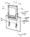
- FIG. 1illustrates an isometric view of one embodiment of a device docking apparatus holding a PDA
- FIG. 2illustrates one embodiment of a PDA removed from a device docking apparatus
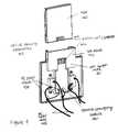
- FIG. 3illustrates an isometric exploded assembly view of one embodiment of a device docking apparatus
- FIG. 4illustrates a rear view of one embodiment of a device docking apparatus
- FIG. 5illustrates a side view of one embodiment of device docking apparatus extending into a junction box
- FIG. 6illustrates a side view of an alternative embodiment of a device docking apparatus extending into a junction box
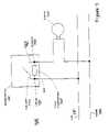
- FIG. 7illustrates a circuit diagram of the embodiment of the device docking apparatus shown in FIG. 5 ;
- FIG. 8shows a circuit diagram of an alternative embodiment of a device docking apparatus
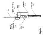
- FIG. 9illustrates a side view of one embodiment of the embodiment of the device docking apparatus of FIG. 8 including a battery
- FIG. 10illustrates an isometric exploded assembly view of one embodiment of a PDA
- FIG. 11illustrates an isometric view of one embodiment of a device docking apparatus including a PDA with an integral charge-coupled device (CCD);
- a PDAwith an integral charge-coupled device (CCD)
- FIG. 12illustrates an isometric view of one embodiment of a device docking apparatus with an integral CCD
- FIG. 13illustrates an isometric view of one embodiment of a device docking apparatus holding a cellular phone
- FIG. 14illustrates an isometric view of one embodiment of a device docking apparatus holding a display module
- FIG. 15shows an isometric view of one embodiment of a display module removed from a device docking apparatus
- FIG. 16illustrates an isometric view of an alternative embodiment of a device docking apparatus fastened to a power outlet module
- FIG. 17illustrates an exploded view of an alternative embodiment of a device docking apparatus fastened over a power outlet module
- FIG. 18illustrates an isometric view of one embodiment of a wall switch device with an integral LCD, softkeys, and CCD with lens;
- FIG. 19illustrates a block schematic diagram of one embodiment of a functional system for the wall switch device shown in FIG. 18 ;
- FIG. 20illustrates an isometric view of one embodiment of a power outlet device with an integral LCD, softkeys, and CCD with lens;
- FIG. 21illustrates a functional block diagram of one embodiment of a system of wall switch devices and a wireless transceiver base
- FIG. 22a functional block diagram of one embodiment of a system of wall switch devices communicating via data signals that are superimposed on AC power wires;
- FIG. 23illustrates a flow diagram of one embodiment of a process of using a device docking apparatus.
- FIG. 24illustrates a flow diagram of an alternative embodiment of a process of using a system including a wall switch device.
- a PDAis a Personal Digital Assistant, a class of personal computer devices that are typically small enough to be carried conveniently by a person.
- a PDAtypically has a liquid crystal display (LCD) that allows the user to write on it with a stylus, or otherwise control and manipulate the software and stored content on the PDA.
- LCDliquid crystal display
- PDAsWhen used in the home, and incorporating a connection to the worldwide web, PDAs are often referred to as webpads.
- a networkis one or more computer devices or electronic devices of any type, such as, for example, but not limited to a personal computer (PC), network appliance, or PDA, connected together by a data transfer link.
- PCpersonal computer
- PDApersonal computer
- a PDA that has a communication link to the Internetis often referred to as a node.
- a node (point of interaction with the Internet) on the networkcan potentially communicate with (i.e. can send or receive data to) any other node (electronic device) on the network.
- Network physical layersmay be wired or they may be wireless.
- the Internetis used interchangeably with the term web or worldwide web. Both of these are defined as the worldwide network of PCs, servers, and other devices.
- a network applianceis defined as a standalone computer device that is a single-purpose device, as opposed to a PC, which can run software to perform a wide variety of tasks.
- a network appliancetypically has a minimal user interface that allows the user to perform a more specific set of tasks.
- a CCDcharged coupled device
- Each CCD chipconsists of an array of light sensitive photocells that, in conjunction with a lens and a microprocessor and memory, can be used to capture both still shots and moving pictures.
- the present inventionincludes a system having a wall switch device and a system having a power outlet device.
- the wall switch devicefastens to a light switch module on a wall.
- the power outlet devicefastens to a power outlet module.
- a wall switch deviceis fastened to a wall switch module and communicates with a network.
- the wall switch deviceincludes a wireless transceiver.
- a wireless transceiver baseenables communication between the wall switch device and the network via a wireless data transfer protocol.
- the wall switch deviceis coupled to power wires. The power wires enable communication between the wall switch device and the network.
- the wall switch deviceincludes a data transceiver to receive and transfer data via the power wires to the network.
- a power outlet deviceis fastened to a power outlet module and communicates with a network.
- the power outlet deviceincludes a wireless transceiver.
- a wireless transceiver baseenables communication between the power outlet device and the network via a wireless data transfer protocol.
- the power outlet deviceis coupled to power wires. The power wires enable communication between the power outlet device and the network.
- the power outlet deviceincludes a data transceiver to receive and transfer data via the power wires to the network.
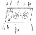
- FIG. 1illustrates an isometric view of one embodiment of a device docking apparatus 100 holding a PDA 150 .
- the device docking apparatus 100may be holding other types of portable electronic devices.
- the wall switch plate 110includes a receptacle 120 that holds a portable electronic device.
- the receptacle 120is a PDA dock that securely retains the PDA 150 on a wall 140 .
- the PDA 150has an LCD 155 and a stylus 160 .
- the PDA 150may include other features.
- the portable electronic device in the device docking apparatusmay be removable from the device docking apparatus as seen in FIG. 2 .
- a componentmay be integral to the device docking apparatus.
- the wall switch plate 110can be retrofitted to any existing light switch electrical junction box.
- the wall switch plate 110may be made so that the device docking apparatus 100 fastens to only one light switch 145 .
- the wall switch plate 110may be made to fasten to more than one light switch 145 as shown in FIG. 1 .
- the docking device apparatus 100attaches to a light switch junction box by a conventional screwing system.
- Wall switch plate crews 130attach the wall switch plate 110 to the junction box (not shown), which exists in the wall 140 .
- FIG. 2illustrates one embodiment of a PDA 240 removed from a device docking apparatus 200 .
- the device docking apparatus 200is fastened to two light switches 250 .
- the device docking apparatus 200includes a wall switch plate 210 and a PDA dock 220 .
- the PDA 240 and stylus 260are removed from the device docking apparatus 200 to show electrical contacts 230 on the device docking apparatus 200 that correspond to electrical contacts 230 (not shown) on the PDA 240 .
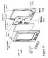
- FIG. 3illustrates an isometric exploded assembly view of one embodiment of a device docking apparatus 300 .
- the device docking apparatus 300is fastened to light switch modules 340 .
- the device docking apparatus 300includes a wall switch plate 310 , a PDA dock 320 , and a control charging module 330 .
- the control charging module 330includes a printed circuit board 332 , integrated circuits 336 , and electrical contacts 334 .
- the control charging modulemay include other electrical components. Further detail is shown in FIG. 4 .
- FIG. 4illustrates a rear view of one embodiment of a device docking apparatus 400 .
- the device docking apparatus 400is fastened to light switch modules.
- the device docking apparatus 400includes a wall switch plate 410 , a PDA dock 420 , and a control charging module 430 .
- the control charging module 430includes electrical contacts 432 which contact corresponding electrical contacts 442 on the PDA 440 when the PDA 440 is placed all the way into the PDA dock 420 . In one embodiment, gravity will suffice to make the electrical contacts 432 and 442 functionally connect.
- FIG. 4also shows that the control charging module 430 includes an AC power input 434 from an AC power wire 450 that extends from the junction box and is connected to the light switch modules 410 .
- the control charging module 430is supplied with power from the AC power wire 450 .
- the control charging module 430modifies the power from AC to DC that is acceptable (battery charging power levels) for the PDAs 440 located in device docking apparatus 400 .
- other additional componentsmay extend into the wall cavity behind the switch plate 410 as is depicted in the embodiment shown in FIG. 5 .
- FIG. 5illustrates a side view of one embodiment of device docking apparatus 500 extending into a junction box 530 .
- the device docking apparatus 500is fastened to a light switch module 520 on a wall 510 .
- AC power wires 540are fed into a junction box 530 in the wall cavity and power the device docking apparatus 500 .
- AC junction boxes 530may be wired in one of two configurations, with both power and neutral wires entering and accessible at the junction box 530 with a switch in between the power and neutral wires. In FIG. 5 , a switch is between the power and neutral wires.
- FIG. 6illustrates a side view of an alternative embodiment of a device docking apparatus 600 extending into a junction box 630 .
- the device docking apparatus 600is fastened to a light switch module 620 on a wall 610 .
- AC power wires 640are fed into the junction box 630 in the wall cavity and power the device docking apparatus 600 .
- a control charging module 605may be located physically toward the rear of the junction box 630 , and functionally connected to a wall switch plate by a ribbon cable 650 . This type of arrangement may be used in instances where there is not enough space for the control charging module 605 to exist between the light switch modules 620 .
- FIG. 7illustrates a circuit diagram of the embodiment of the device docking apparatus 700 shown in FIG. 5 .
- Power taps 735 from 120 volts (V) power 730 and neutral taps 745 from neutral 740are connected to the control charging module 760 and light bulb 750 in the light junction box 710 .
- the charging systemincludes a power conversion function using an AC rectifier circuit and a linear power supply device. AC power conversion such as this is known in the field of electronic product design.
- FIG. 8shows a circuit diagram of an alternative embodiment of a device docking apparatus 800 .
- the power 830 side of the circuitenters and is accessible at the junction box 810 to power a light bulb 850 . Accordingly, a different method is required to charge or otherwise power an electronic device.
- a systemis used whereby a small amount of current is allowed to flow through low-power conversion circuit, and power is derived from this current flow.
- a small amount of currentis allowed to flow through the light circuit.
- the currentis so small that the light filament is emitting little or no visible light. Because the current must be kept small enough to keep the light bulb 850 filament from emitting light when the switch 820 is off, this system also includes a battery 870 that is constantly trickle charged.
- FIG. 9illustrates a side view of one embodiment of the embodiment of the device docking apparatus 900 of FIG. 8 including a battery 950 .
- the battery 950is installed in the junction box 930 and provides substantial power for electronic devices docked in a device docking apparatus 900 at the wall 910 .
- the device docking apparatus 900is fastened to a light switch module 920 on the wall 910 .
- AC power wires 940are fed into a junction box 930 in the wall cavity and power the device docking apparatus 900 via the control charging module 905 .
- FIG. 10illustrates an isometric exploded assembly view of one embodiment of a PDA 1000 .
- the PDA 1000 shown hereis similar to PDAs that currently exist on the market as standalone PDA devices.
- the size of the PDA 1000is that which can be conveniently and easily hand held.
- the constructionis of a typical two-piece plastic shell construction including a PDA front housing 1010 and a PDA rear housing 1040 .
- the PDA 1000includes an LCD 1020 that contains an integral backlight so that the display may be read in low light.
- the PDAmay also include control buttons 1015 to operate the PDA 1000 .
- the PDA 1000also includes a wireless transceiver integrated circuit 1032 and an antenna 1034 .
- the PDA 1000also includes electrical contacts 1042 and/or batteries 1044 to power the PDA 1000 .
- FIG. 10shows that the antenna is located internal to the PDA 1000 , mounted to the printed circuit board.
- the wireless system that may be used in the PDA 1000is an IEEE 802.11b system, manufactured by Intersil, Incorporated.
- other wireless communication protocolssuch as BluetoothTM may be used.
- Batteries 1044are also shown in FIG. 10 so that the PDA 1000 may operate when removed from a device docking apparatus.
- the entire assemblymay be held together with threaded fasteners or any type of commonly used fastening system, including plastic snap-fits.
- FIG. 11illustrates an isometric view of one embodiment of a device docking apparatus 1100 including a PDA 1060 with an integral charge-coupled device (CCD) 1164 .
- the device docking apparatus 1100is fastened using switch plate screws 1130 to a light switch 1150 on a wall 1140 .
- the device docking apparatus 1100includes a wall switch plate 1110 and a receptacle 1120 in the form of a PDA dock.
- a PDA 1160is shown with an LCD 1162 , a stylus 1170 , and a CCD 1164 with a lens.
- a CCD 1164is a semiconductor that is used to make a digital camera that is capable of taking still shots or moving pictures.
- the PDAs 1100there is circuitry and other integrated circuits in the PDA 1100 on the printed circuit board that combine to form a subsystem for capturing and transmitting digital images via a wireless communication link between the PDA 1100 and a home server or the Internet.
- the PDAs 1100also include optional CCD camera plug-on adapters.
- One example of a PDAis the Palm Pilot, manufactured by Palm Computing.
- Another example of a PDAis Visor, manufactured by Handspring. Both the Palm Pilot and Visor offer such optional CCD camera plug-on adapters.
- FIG. 12illustrates an isometric view of one embodiment of a device docking apparatus 1200 with an integral CCD 1250 .
- the device docking apparatus 1200is similar to those shown in the previous figures and is fastened using wall switch plate screws 1240 to light switch modules 1270 on a wall 1260 .
- the device docking apparatus 1200includes a wall switch plate 1210 and a receptacle in the form of a PDA dock 1220 . Electrical contacts 1230 may also be seen to contact corresponding electrical contacts on a portable electronic device. All the necessary circuitry for capturing and transmitting digital images is included on the control charging module (not shown). In one example, a remote user may able to access the output of the camera function at a device docking apparatus 1200 in their home regardless of whether or not the PDA is docked with the wall switch plate 1210 .
- FIG. 13illustrates an isometric view of one embodiment of a device docking apparatus 1300 holding a cellular phone 1360 .
- the device docking apparatus 1300is fastened using wall switch plate screws 1330 to light switch modules 1350 on a wall 1340 .
- the device docking apparatus 1300includes a wall switch plate 1310 and a receptacle 1320 that holds the cellular phone 1360 .
- the cellular phone 1360includes an LCD 1362 and buttons 1364 . Docking the cellular phone 1360 in the device docking apparatus 1300 allows the cellular phone 1360 to be conveniently stored and charged using the power supplied to the light switches 1350 .
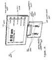
- FIG. 14illustrates an isometric view of one embodiment of a device docking apparatus 1400 holding a display module 1450 .
- the display module 1450is similar to a PDA but with a larger LCD 1452 .
- the display module 1450may be removable from the device docking apparatus 1400 as seen in FIG. 15 .
- the display module 1450may be a component that is integral to the device docking apparatus 1400 .
- the display module 1450is docked in the device docking apparatus 1400 , which is fastened using wall switch plate screws 1430 over light switches 1445 on a wall 1440 .
- the device docking apparatus 1400includes a wall switch plate 1410 and receptacle 1420 that holds the display module 1450 .
- the display module 1450includes buttons 1454 that are placed vertically along the right side of the LCD 1452 . In this configuration, with the buttons 1454 close to the LCD 1452 , each button 1454 can be labeled with text on the LCD 1452 near a corresponding button.
- the display module 1450may also have a stylus that can be stored in the display module 1450 housing.
- FIG. 14shows how, in one embodiment, each button 1454 might be labeled with a relevant item of content. For example, when a button 1454 corresponding to a softkey label is pressed, information of the type designated by the softkey label is presented to a user on the LCD 1452 .
- FIG. 15shows an isometric view of a display module 1530 removed from a device docking apparatus 1500 .
- FIG. 15is similar to the embodiment shown in FIG. 14 .
- the device docking apparatus 1500includes a wall switch plate 1510 and a receptacle in the form of a display module dock 1520 .
- the display module 1530has a contact plate 1536 that fits into the display module dock 1520 so that the display module 1530 is docked in the device docking apparatus 1500 .
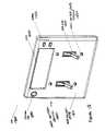
- FIG. 16illustrates an isometric view of an alternative embodiment of a device docking apparatus 1600 fastened to a power outlet module 1660 .
- the device docking apparatusis fastened to the power outlet module 1660 on a wall 1650 using power outlet plate screws 1630 .
- the device docking apparatus 1600 in FIG. 16functions in the same manner as the device docking apparatus 100 shown in FIG. 1 by facilitating the charging, storage and operation of a docked portable electronic device.
- a device docking apparatus 1600 of this typemay be used in places where power outlets are conveniently located, such as above a dresser or kitchen counter.
- the device docking apparatus 1600includes a power outlet plate 1610 , a receptacle in the form of a PDA dock 1620 , and electrical contacts 1640 that would correspond to electrical contacts on a PDA.
- the portable electronic devicemay be removable from the device docking apparatus 1600 .
- the portable electronic devicemay be a component that is integral to the device docking apparatus 1600 .
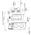
- FIG. 17illustrates an exploded view of one embodiment of a device docking apparatus 1700 fastened to a power outlet module 1740 including electrical contact screws 1742 .
- the device docking apparatus 1700includes a power outlet plate 1710 , a PDA dock 1720 , and a control charging module 1730 .
- the control charging module 1730includes a printed circuit board with integrated circuits and other electronic components, 1732 and electrical contacts 1734 .
- the control charging module 1730is similar to the one used in the embodiment shown in FIG. 3 , except that the printed circuit board is designed to accommodate the different geometry of the power outlet module 1740 rather than a light switch module.
- FIG. 18illustrates an isometric view of one embodiment of a wall switch device 1800 with an integral LCD 1820 , softkeys 1830 , and CCD with lens 1840 .
- the wall switch device 1800includes a wall switch plate 1810 that is fastened to light switches 1870 on a wall 1860 with wall switch plate screws 1850 .
- the wall switch device 1800does not act as a charging dock for other portable electronic devices. Rather, the wall switch device 1800 is used as a point of contact with a network of other wall switch devices 1800 or a network such as the Internet.
- Informationis displayed on the LCD 1820 and manipulated with softkeys 1830 located near the LCD 1820 . All the necessary circuitry for manipulation and control of the LCD 1820 , softkeys 1830 , and CCD 1840 are included on the control charging module (not shown).
- FIG. 19illustrates a block schematic diagram of one embodiment of a functional system 1900 for the wall switch device 1800 shown in FIG. 18 .
- a control charging module(not shown) in the wall switch device 1900 may include any of the following integrated hardware: transformer and AC/DC power conversion 1920 , processor 1940 , memory 1910 , input devices (softkeys) 1930 , display driver/display 1970 , CCD 1950 , and network interface card (NIC) 1960 .
- FIGS. 18 and 19show an example that includes both the LCD and CCD, an alternate embodiment may include a wall switch device with only an LCD, or only a CCD with lens.
- FIG. 20illustrates an isometric view of one embodiment of a power outlet device 2000 with an integral LCD 2020 , softkeys 2030 , and CCD with lens 2040 .
- the power outlet device 2000is similar to the wall switch device 1800 shown in FIG. 18 except the power outlet device 2000 includes a power outlet plate 2010 that is fastened to a power outlet module 2070 on a wall 2060 using power outlet plate screws 2050 . Accordingly, the power outlet device 2000 may be used both as a power outlet and as a point of contact with a network of other power outlet devices, or other types of devices, and/or with a network such as the Internet.
- FIG. 20shows an embodiment that includes both the LCD and CCD incorporated in a power outlet device
- an alternate embodimentmay only include a LCD, or only a CCD with lens.
- FIG. 21illustrates a functional block diagram of one embodiment of a system 2100 of wall switch devices 2120 , 2130 , 2140 , 2150 , 2160 , and 2170 and a wireless transceiver base 2110 .
- wall switch devices 2120 , 2130 , 2140 , 2150 , 2160 , and 2170are located in rooms around any building, such as a house, at the light switch location near the entry doorway to the room.
- the wall switch devices 2120 , 2130 , 2140 , 2150 , 2160 , and 2170are similar to that shown in FIG. 18 with an integrated LCD, softkeys, and CCD with lens.
- a device docking apparatussuch as one illustrated in FIG. 1 may be used in the system described above.
- a control charging module (not shown) in each wall switch device 2120 , 2130 , 2140 , 2150 , 2160 , and 2170is connected to the AC power wires 2118 that run to that respective junction box.
- the control charging module for the embodiment shown in FIG. 21may be in a device docking apparatus 100 as shown in FIG. 1 and only have the purpose of charging batteries in a portable electronic device docked in the device docking apparatus from the line power. As discussed above the power must be converted from AC to DC, with the correct current and voltage supplied.
- FIG. 21shows that there is communication between each wall switch device, via a wireless data transfer protocol, and communication to either a local home server 2112 , and/or via a gateway 2112 to a server located external to the home anywhere on the Internet 2116 via an Internet connection 2114 .
- Each wall switch devicealso includes a wireless local area network (LAN) transceiver functionally connected to the control charging module.
- the Internet connection 2114may be dial-up, cable, or DSL.
- the datais transferred first to the wireless transceiver base 2110 in the vicinity of the wall switch devices 2120 , 2130 , 2140 , 2150 , 2160 , and 2170 .
- the wireless transceiver base 2110communicates to each wall switch device 2120 , 2130 , 2140 , 2150 , 2160 , and 2170 via a wireless data transfer protocol.
- the wireless data transfer protocol that is used for local area communicationsis a system based on the IEEE 802.11b wireless communication standard.
- a wireless hub systemsuch as an 802.11b system has a range of approximately 150 feet so it would be able to reach wall switch devices in a typical house. This architecture allows access to information the home server and/or the Internet via each wall switch device.
- the wireless transfer protocolmay be BluetoothTM.
- Wireless LAN systemssuch as IEEE 802.11b are able to function in ad-hoc mode, where there is no central hub.
- Each switch deviceis a node on the network and can communicate with any other switch device within range of the radio-frequency field. Therefore, switch devices may be added at greater distances as long as each device is in communication contact with at least one other wireless LAN device.
- each portable electronic device docked or not docked in wall switch devices 2120 , 2130 , 2140 , 2150 , 2160 , and 2170via the wireless transceiver base 2110 in addition to communication to either the local home server 2112 , and/or via a gateway 2112 to a server located external to the home anywhere on the Internet 2114 .
- the datais transferred first to the wireless transceiver base in the vicinity of the portable electronic devices.
- the wireless systemprovides a discrete identifier or ID, for each of the wall switch devices 2120 , 2130 , 2140 , 2150 , 2160 , and 2170 .
- IDthe source of the information that is entered or modified on a wall switch device 2120 , 2130 , 2140 , 2150 , 2160 , and 2170 may be tracked by other wall switch device 2120 , 2130 , 2140 , 2150 , 2160 , and 2170 or by the home server 2112 .
- An organizing software applicationis used to associate a user defined name to each wall switch device, in addition to the discrete class C network IP address such as a 192.168.1.X address specified for use in dynamic host configuration protocol (DHCP) systems.
- DHCPdynamic host configuration protocol
- one switch devicehas a class C IP address but is also referred to as “master bedroom” switch device.
- FIG. 21is an illustration of a system including wall switch devices.
- power outlet devices or device docking apparatus that fasten to power outlet modulesmay be used instead of wall switch devices and device docking apparatus that fasten to wall switch modules.
- FIG. 22a functional block diagram of one embodiment of a system of wall switch devices 2230 , 2240 , 2250 , 2260 , 2270 , and 2280 communicating via data signals 2222 that are superimposed on AC power wires 2220 .
- Intellon, Inc.is a provider of integrated circuits for sending and receiving data over AC power lines.
- the system 2200 shown in FIG. 22shows the information transfer between the wall switch devices 2230 , 2240 , 2250 , 2260 , 2270 , and 2280 .
- Each wall switch device 2230 , 2240 , 2250 , 2260 , 2270 , and 2280is connected to the power system wiring 2220 at each junction box.
- the control charging module of each wall switch device 2230 , 2240 , 2250 , 2260 , 2270 , and 2280must also include a LAN data transceiver (not shown) because the transfer of data between the wall switch devices 2230 , 2240 , 2250 , 2260 , 2270 , and 2280 uses the power wiring 2220 as the medium, with data signals 2222 superimposed on the AC fluctuation but at a much higher frequency.
- the data transceiverfilters out the low frequency AC voltage, de-modulates and otherwise digitally processes the data signal, and transfers the information superimposed on the AC wiring to the wall switch devices 2230 , 2240 , 2250 , 2260 , 2270 , and 2280 . It also isolates the wall switch device electrical system from the high voltage home wiring system.
- the Internet connection 2212may be dial-up, cable, or DSL. This type of communication requires a wireless data transfer protocol.
- the datais transferred first to the wireless transceiver base 2210 in the vicinity of the wall switch devices 2230 , 2240 , 2250 , 2260 , 2270 , and 2280 .
- the wireless transceiver base 2210communicates with each wall switch device 2230 , 2240 , 2250 , 2260 , 2270 , and 2280 via the wireless data transfer protocol.
- the wireless data transfer protocol that is used for local area communicationsis a system based on the IEEE 802.11b wireless communication standard.
- a wireless hub systemsuch as an 802.11b system has a range of approximately 150 feet so it would be able to reach wall switch devices in a typical house.
- This architectureallows access to information the home server 2214 and/or the Internet via each wall switch device 2230 , 2240 , 2250 , 2260 , 2270 , and 2280 .
- the wireless communication protocolmay be BluetoothTM.
- each portable electronic device docked or not docked in wall switch devices 2230 , 2240 , 2250 , 2260 , 2270 , and 2280there may also be communication between each portable electronic device docked or not docked in wall switch devices 2230 , 2240 , 2250 , 2260 , 2270 , and 2280 .
- the system 2200 of FIG. 2200may use device docking apparatus as shown and described in FIG. 1 .
- the portable electronic devicesmay communicate by sending data packets 2222 using the AC power wires 2220 as the medium. Accordingly, the portable electronic devices must be docked in the device docking apparatus in order to communicate with other portable electronic devices also docked in various device docking apparatus.
- the portable electronic devicesmay communicate with one another and the local home server 2214 via the wireless transceiver base 2210 even without being docked in any device docking apparatus.
- the portable electronic devicesmay communicate with a server 2214 located external to the home anywhere on the Internet via a gateway. Regardless of where the actual data destination is away from the portable electronic devices, in the latter described embodiment, the data is transferred first to the wireless transceiver base 2210 in the vicinity of the portable electronic devices.
- the wireless systemprovides a discrete identifier or ID, for each of the wall switch devices 2230 , 2240 , 2250 , 2260 , 2270 , and 2280 .
- IDa discrete identifier or ID
- the source of the information that is entered or modified on a wall switch device 2230 , 2240 , 2250 , 2260 , 2270 , and 2280may be tracked by another wall switch device 2230 , 2240 , 2250 , 2260 , 2270 , and 2280 or the server 2214 .
- FIG. 22is an illustration of a system including wall switch devices.
- power outlet devices or device docking apparatus that fasten to power outlet modulesmay be used instead of wall switch devices and device docking apparatus that fasten to wall switch modules.
- FIG. 23illustrates a flow diagram of one embodiment of a process 2300 of using a device docking apparatus.
- processing block 2310it is determined if power is to be supplied from a wall switch module.
- processing block 2330a portable electronic device is placed in a receptacle of the device docking apparatus.
- the device docking apparatusis fastened to a light module on a wall.
- poweris supplied to the portable electronic device docked in the device docking apparatus via taps from power wires connected to the light switch module.
- datais received from a network through the power wires to the device docking apparatus via a data transceiver on the device docking apparatus.
- the datais transferred to the portable electronic device when the portable electronic device is docked in the device docking apparatus.
- datais transferred from the portable electronic device to the device docking apparatus when the portable electronic device is docked in the device docking apparatus.
- datais sent from the device docking apparatus to the network through the power wires.
- processing block 2310if no, the process moves to processing block 2320 where it is determined if power is to be supplied from a power outlet module. If no, the process moves back to processing block 2310 .
- a portable electronic deviceis placed in a receptacle of the device docking apparatus.
- the device docking apparatusis fastened to a power outlet module.
- poweris supplied to the portable electronic device docked in the device docking apparatus via a tap from power wires connected to the power outlet module.
- datais received from a network through the power wires to the device docking apparatus via a data transceiver on the device docking apparatus.
- the datais transferred to the portable electronic device when the portable electronic device is docked in the device docking apparatus.
- datais transferred from the portable electronic device to the device docking apparatus when the portable electronic device is docked in the device docking apparatus.
- datais sent from the device docking apparatus to the network through the power wires.
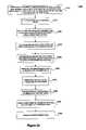
- FIG. 24illustrates a flow diagram of an alternative embodiment of a process 2400 of using a system including a wall switch device.
- datais received from a network through power wires connected to a power input.
- the power inputis coupled to a wall switch device fastened to a light switch module on a wall.
- the wall switch devicereceives the data via a data transceiver on the wall switch device.
- the datais communicated back to the network.
- datais communicated between the wall switch device and the network via a wireless transfer protocol using a transceiver base.
- datais communicated between a server and the wall switch device using the wireless transceiver base.
- datais communicated between the server and the wall switch device using a gateway connected to the server and the wireless transceiver base.
- the wall switch deviceis identified by having an identifier on the wall switch device.
- informationis displayed on a display integral to the wall switch device.
- informationis inputted via a user interface on the display module of the wall switch device.
- digital imagesare captured via a charge-coupled device and lens integral to the wall switch device.
- digital imagesare received and transmitted using the wireless transfer protocol.
- FIG. 24shows an embodiment of a process with wall switch devices. However, in an alternative embodiment, a similar process may use power outlet devices.
Landscapes
- Engineering & Computer Science (AREA)
- Signal Processing (AREA)
- Computer Networks & Wireless Communication (AREA)
- Theoretical Computer Science (AREA)
- Human Computer Interaction (AREA)
- Automation & Control Theory (AREA)
- Power Engineering (AREA)
- Computer Hardware Design (AREA)
- Physics & Mathematics (AREA)
- General Engineering & Computer Science (AREA)
- General Physics & Mathematics (AREA)
- Microelectronics & Electronic Packaging (AREA)
- Charge And Discharge Circuits For Batteries Or The Like (AREA)
- Remote Monitoring And Control Of Power-Distribution Networks (AREA)
Abstract
Description
Claims (24)
Priority Applications (3)
| Application Number | Priority Date | Filing Date | Title |
|---|---|---|---|
| US09/921,195US6993289B2 (en) | 2000-08-02 | 2001-08-01 | System including a wall switch device and a system including a power outlet device and methods for using the same |
| PCT/US2001/024496WO2002011367A2 (en) | 2000-08-02 | 2001-08-02 | A local area network system including a wall switch device and/or a power outlet device and methods for using the same |
| AU2001279191AAU2001279191A1 (en) | 2000-08-02 | 2001-08-02 | A system including a wall switch device and a system including a power outlet device and methods for using the same |
Applications Claiming Priority (2)
| Application Number | Priority Date | Filing Date | Title |
|---|---|---|---|
| US22250000P | 2000-08-02 | 2000-08-02 | |
| US09/921,195US6993289B2 (en) | 2000-08-02 | 2001-08-01 | System including a wall switch device and a system including a power outlet device and methods for using the same |
Publications (2)
| Publication Number | Publication Date |
|---|---|
| US20020052138A1 US20020052138A1 (en) | 2002-05-02 |
| US6993289B2true US6993289B2 (en) | 2006-01-31 |
Family
ID=26916865
Family Applications (1)
| Application Number | Title | Priority Date | Filing Date |
|---|---|---|---|
| US09/921,195Expired - LifetimeUS6993289B2 (en) | 2000-08-02 | 2001-08-01 | System including a wall switch device and a system including a power outlet device and methods for using the same |
Country Status (3)
| Country | Link |
|---|---|
| US (1) | US6993289B2 (en) |
| AU (1) | AU2001279191A1 (en) |
| WO (1) | WO2002011367A2 (en) |
Cited By (47)
| Publication number | Priority date | Publication date | Assignee | Title |
|---|---|---|---|---|
| US20050010954A1 (en)* | 2003-07-09 | 2005-01-13 | Serconet Ltd. | Modular outlet |
| US20050025162A1 (en)* | 2002-11-13 | 2005-02-03 | Yehuda Binder | Addressable outlet, and a network using same |
| US20050063403A1 (en)* | 2001-07-05 | 2005-03-24 | Serconet Ltd. | Telephone outlet with packet telephony adaptor, and a network using same |
| US20050111636A1 (en)* | 1999-07-20 | 2005-05-26 | Serconet, Ltd | Network for telephony and data communication |
| US20050117603A1 (en)* | 2000-04-18 | 2005-06-02 | Serconet, Ltd. | Telephone communication system over a single telephone line |
| US20050180561A1 (en)* | 2004-02-16 | 2005-08-18 | Serconet Ltd. | Outlet add-on module |
| US20060018338A1 (en)* | 1998-07-28 | 2006-01-26 | Serconet, Ltd. | Local area network of serial intelligent cells |
| US20060098638A1 (en)* | 2001-10-11 | 2006-05-11 | Serconet Ltd. | Outlet with analog signal adapter, a method for use thereof and a network using said outlet |
| US20060197428A1 (en)* | 2005-02-21 | 2006-09-07 | Takeshi Tonegawa | Electron devices with non-evaporation-type getters and method for manufacturing the same |
| US20070124418A1 (en)* | 2004-01-13 | 2007-05-31 | Yehuda Binder | Information device |
| US20080266776A1 (en)* | 2007-04-26 | 2008-10-30 | Robin Peng | Modular Computer System |
| US20090174998A1 (en)* | 2004-09-09 | 2009-07-09 | Scott Struthers | Computer Wall Docking Station |
| US20100052577A1 (en)* | 2008-09-03 | 2010-03-04 | Michael Scott Brownlee | Power supply system for a building |
| US20100085894A1 (en)* | 2006-10-27 | 2010-04-08 | Outsmart Power Systems, Llc | Apparatus And Method For Mapping A Wired Network |
| US7761555B1 (en)* | 2002-08-06 | 2010-07-20 | Richard Anthony Bishel | Internet/intranet-connected AC electrical box |
| US7873058B2 (en) | 2004-11-08 | 2011-01-18 | Mosaid Technologies Incorporated | Outlet with analog signal adapter, a method for use thereof and a network using said outlet |
| US20110040862A1 (en)* | 2009-08-11 | 2011-02-17 | Canon Kabushiki Kaisha | Communication system having management apparatus and user apparatus, management apparatus, user apparatus, and method of controlling the same |
| US20110109301A1 (en)* | 2008-05-08 | 2011-05-12 | Outsmart Power Systems, Llc | Device And Method For Measuring Current And Power In A Plug Or Receptacle |
| US20110182012A1 (en)* | 2008-07-23 | 2011-07-28 | Hilton Paul C M | Providing Additional Electrical Functionality To A Node |
| US20110187323A1 (en)* | 2010-02-03 | 2011-08-04 | James Robert Gourley | Mobile Electronic Device AC Charger Mount |
| US20110210717A1 (en)* | 2008-09-05 | 2011-09-01 | Hilton Paul C M | Apparatus and Methods for Mapping a Wired Network |
| US8582598B2 (en) | 1999-07-07 | 2013-11-12 | Mosaid Technologies Incorporated | Local area network for distributing data communication, sensing and control signals |
| US20140075075A1 (en)* | 2012-09-11 | 2014-03-13 | Google Inc. | Context-Dependent Home Automation Controller and Docking Station |
| WO2014047634A1 (en)* | 2012-09-24 | 2014-03-27 | Richard Palmeri | Modular multifunction system for installation or retrofit of controls, outlets, and sensors |
| US20140368989A1 (en)* | 2013-06-13 | 2014-12-18 | Hanni B. Lozano | Power line docking station apparatus |
| US9438052B1 (en) | 2015-03-27 | 2016-09-06 | Ellen Louise Cole | Mobile device holder-charger |
| US9565089B2 (en) | 2010-11-12 | 2017-02-07 | Outsmart Power Systems, Llc | Maintaining information integrity while minimizing network utilization of accumulated data in a distributed network |
| US20170338605A1 (en)* | 2014-11-07 | 2017-11-23 | Schneider Electric Industries Sas | Electrical connection point mounted in a wall in a dwelling and electrical installation comprising at least one such connection point |
| US10139790B2 (en) | 2015-06-10 | 2018-11-27 | Vivint, Inc. | Powered faceplate integration |
| US10340722B2 (en) | 2015-06-05 | 2019-07-02 | Pass & Seymour, Inc. | Electrical wiring assembly |
| US10389149B2 (en)* | 2014-11-05 | 2019-08-20 | SILVAIR Sp. z o.o. | Sensory and control platform for an automation system |
| WO2019246607A1 (en) | 2018-06-22 | 2019-12-26 | Kleverness Incorporated | Retrofit smart home controller device with power supply module, charger and dock |
| US10672252B2 (en) | 2015-12-31 | 2020-06-02 | Delta Faucet Company | Water sensor |
| US10951052B2 (en) | 2015-06-05 | 2021-03-16 | Pass & Seymour, Inc. | Wireless charger |
| US11189975B1 (en)* | 2017-05-07 | 2021-11-30 | Jeffrey P. Baldwin | Powered wall plate |
| US11394157B2 (en) | 2011-08-01 | 2022-07-19 | Snaprays, Llc | Active cover plates |
| US20220268425A1 (en)* | 2021-02-19 | 2022-08-25 | J & J Properties of Cortland, LLC | Easy mount lighting fixture and electrical receptacle system |
| US11495422B2 (en)* | 2015-04-20 | 2022-11-08 | Lutron Technology Company Llc | Control devices having independently suspended buttons for controlled actuation |
| US11715918B1 (en) | 2017-05-07 | 2023-08-01 | Titan3 Technology LLC | Powered wall plate with plug prongs |
| US11715917B1 (en) | 2017-05-07 | 2023-08-01 | Titan3 Technology LLC | Powered wall plate |
| US11888301B2 (en) | 2011-08-01 | 2024-01-30 | Snaprays, Llc | Active cover plates |
| US11949183B1 (en) | 2019-06-04 | 2024-04-02 | Titan3 Technology LLC | Powered wall plate with keyed interface |
| US12095249B1 (en) | 2021-02-05 | 2024-09-17 | Titan3 Technology LLC | Powered wall plate with adjustable plug prongs |
| US12142880B2 (en) | 2011-08-01 | 2024-11-12 | Snaprays, Llc | Active cover plates |
| US12327956B1 (en) | 2022-02-01 | 2025-06-10 | Titan3 Technology LLC | Two-part powered electrical wall plate |
| US12335593B2 (en) | 2020-12-30 | 2025-06-17 | Titan3 Technology LLC | Electrical receptacle with built-in camera |
| US12418711B1 (en) | 2019-04-23 | 2025-09-16 | Titan3 Technology LLC | Electrical wall plate with movably positionable camera |
Families Citing this family (44)
| Publication number | Priority date | Publication date | Assignee | Title |
|---|---|---|---|---|
| US6575908B2 (en)* | 1996-06-28 | 2003-06-10 | Sonosite, Inc. | Balance body ultrasound system |
| US8116889B2 (en)* | 2002-06-27 | 2012-02-14 | Openpeak Inc. | Method, system, and computer program product for managing controlled residential or non-residential environments |
| US7933945B2 (en)* | 2002-06-27 | 2011-04-26 | Openpeak Inc. | Method, system, and computer program product for managing controlled residential or non-residential environments |
| US7987489B2 (en) | 2003-01-07 | 2011-07-26 | Openpeak Inc. | Legacy device bridge for residential or non-residential networks |
| GB2410137A (en)* | 2004-01-19 | 2005-07-20 | David John Dixson | Wireless network |
| GB2449098A (en)* | 2007-05-10 | 2008-11-12 | Timothy Jerome Randall Tierney | Wall mounted battery charger |
| DE102007063586A1 (en)* | 2007-12-21 | 2009-07-02 | Merten Gmbh & Co. Kg | installation arrangement |
| GB0807590D0 (en) | 2008-04-25 | 2008-06-04 | Ominplug Technologies Ltd | Data synchronisation |
| DE102009017265A1 (en)* | 2009-04-11 | 2010-10-21 | Abb Ag | Electrical installation device with charger for a mobile phone |
| CN102598629B (en)* | 2009-06-03 | 2016-08-03 | Abb技术有限公司 | For issuing the method and system of data from intelligent electronic device |
| KR101867812B1 (en)* | 2009-10-21 | 2018-06-18 | 엘지전자 주식회사 | A network system supplying electric power and a control method thereof |
| ITMC20090233A1 (en)* | 2009-11-13 | 2011-05-14 | Alessandro Carlorosi | ELECTRIC BOX INSTALLED ON THE WALL AND ITS FRUIT. |
| DE102010037344A1 (en) | 2010-09-06 | 2012-03-08 | Armin Reisch | Holder for attaching e.g. portable media player at frame of personal computer display, has opening comprising geometry for feedthrough of cable connected with plug connector, where connector is removed and/or detached from base body |
| DE102012003197B4 (en)* | 2012-02-17 | 2014-06-05 | Ecobility Gmbh | socket |
| WO2014004553A1 (en) | 2012-06-25 | 2014-01-03 | Xceedid Corporation | Access credential reader connector |
| MA35691B1 (en)* | 2013-05-03 | 2014-12-01 | Ahmed Karim Guessous | 230v 230v wall outlet integrates a 12v charger for all mobile phones |
| JP5922165B2 (en)* | 2014-02-21 | 2016-05-24 | ホシデン株式会社 | Charging holder |
| US10996645B1 (en) | 2017-04-01 | 2021-05-04 | Smart Power Partners LLC | Modular power adapters and methods of implementing modular power adapters |
| US10727731B1 (en) | 2017-04-01 | 2020-07-28 | Smart Power Partners, LLC | Power adapters adapted to receive a module and methods of implementing power adapters with modules |
| US12093004B1 (en) | 2017-04-01 | 2024-09-17 | Smart Power Partners LLC | In-wall power adapter and method of implementing an in-wall power adapter |
| US10530597B1 (en) | 2017-04-01 | 2020-01-07 | Smart Power Partners LLC | System for controlling a plurality of power switches configured to apply power to devices |
| US12027968B2 (en) | 2017-04-01 | 2024-07-02 | John J. King | Power adapters and methods of implementing a power adapter |
| WO2019011403A1 (en)* | 2017-07-10 | 2019-01-17 | Berker Gmbh & Co. Kg | Electrical equipment and additional functional module associated therewith |
| BR112020000644A2 (en)* | 2017-07-10 | 2020-07-14 | Berker Gmbh & Co. Kg | electrical equipment and associated additional functional module |
| EP3652828A1 (en)* | 2017-07-10 | 2020-05-20 | Berker GmbH & Co. KG | Electrical equipment and additional functional module associated therewith |
| CN108594777B (en)* | 2018-04-20 | 2020-03-13 | 百度在线网络技术(北京)有限公司 | Intelligent household control method, device, equipment, system and storage medium |
| US10535965B1 (en) | 2019-01-25 | 2020-01-14 | Dell Products, L.P. | Assembly of worldwide AC adapter supporting foldable prongs |
| US11189948B1 (en) | 2019-06-30 | 2021-11-30 | Smart Power Partners LLC | Power adapter and method of implementing a power adapter to provide power to a load |
| US11043768B1 (en) | 2019-06-30 | 2021-06-22 | Smart Power Partners LLC | Power adapter configured to provide power to a load and method of implementing a power adapter |
| US10965068B1 (en) | 2019-06-30 | 2021-03-30 | Smart Power Partners LLC | In-wall power adapter having an outlet and method of controlling an in-wall power adapter |
| US12066848B1 (en) | 2019-06-30 | 2024-08-20 | Smart Power Partners LLC | In-wall power adaper adapted to receive a control attachment and method of implementing a power adapter |
| US11219108B1 (en) | 2019-06-30 | 2022-01-04 | Smart Power Partners LLC | Power adapter arrangement and method of implementing a power adapter arrangement |
| US11460874B1 (en) | 2019-06-30 | 2022-10-04 | Smart Power Partners LLC | In-wall power adapter configured to control the application of power to a load |
| US11579640B1 (en) | 2019-06-30 | 2023-02-14 | Smart Power Partners LLC | Control attachment for an in-wall power adapter |
| US10917956B1 (en) | 2019-06-30 | 2021-02-09 | Smart Power Partners LLC | Control attachment configured to provide power to a load and method of configuring a control attachment |
| US12045071B1 (en) | 2019-06-30 | 2024-07-23 | Smart Power Partners LLC | In-wall power adapter having an outlet |
| US12164350B1 (en) | 2019-06-30 | 2024-12-10 | Smart Power Partners LLC | Power adapter configured to provide power to a load |
| US10958020B1 (en) | 2019-06-30 | 2021-03-23 | Smart Power Partners LLC | Control attachment for an in-wall power adapter and method of controlling an in-wall power adapter |
| US11231730B1 (en) | 2019-06-30 | 2022-01-25 | Smart Power Power LLC | Control attachment for a power adapter configured to control power applied to a load |
| US11264769B1 (en) | 2019-06-30 | 2022-03-01 | Smart Power Partners LLC | Power adapter having contact elements in a recess and method of controlling a power adapter |
| US10938168B2 (en) | 2019-06-30 | 2021-03-02 | Smart Power Partners LLC | In-wall power adapter and method of controlling the application of power to a load |
| US11201444B1 (en) | 2019-06-30 | 2021-12-14 | Smart Power Partners LLC | Power adapter having contact elements in a recess and method of controlling a power adapter |
| US10958026B1 (en) | 2019-06-30 | 2021-03-23 | Smart Power Partners LLC | Contactless thermometer for an in-wall power adapter |
| US12160074B2 (en) | 2021-11-03 | 2024-12-03 | Smart Power Partners LLC | In-wall power adapter having a switch and a recess adapted to receive a control module |
Citations (26)
| Publication number | Priority date | Publication date | Assignee | Title |
|---|---|---|---|---|
| US3739226A (en)* | 1971-09-08 | 1973-06-12 | W Seiter | Emergency light unit for mounting to an electrical wall outlet |
| US5210788A (en) | 1986-10-22 | 1993-05-11 | Nilssen Ole K | Telephone instrument and distribution system |
| JPH06113032A (en) | 1992-09-25 | 1994-04-22 | Matsushita Electric Works Ltd | Telephone system |
| US5473517A (en)* | 1995-01-23 | 1995-12-05 | Blackman; Stephen E. | Emergency safety light |
| US5539821A (en)* | 1995-01-24 | 1996-07-23 | At&T Corp. | Power outlet mount for a portable telephone |
| US5708705A (en)* | 1994-04-28 | 1998-01-13 | Nec Corporation | Wallhung arrangement for a cordless telephone |
| US5838226A (en) | 1996-02-07 | 1998-11-17 | Lutron Electronics Co.Inc. | Communication protocol for transmission system for controlling and determining the status of electrical devices from remote locations |
| EP0878936A2 (en) | 1997-05-12 | 1998-11-18 | Victor Company Of Japan, Limited | Communication system and circuit controller |
| US5905467A (en)* | 1997-07-25 | 1999-05-18 | Lucent Technologies Inc. | Antenna diversity in wireless communication terminals |
| EP0921658A2 (en) | 1997-11-26 | 1999-06-09 | International Business Machines Corporation | A method and apparatus for an automatic multi-rate wireless/wired computer network |
| US5941648A (en)* | 1998-10-21 | 1999-08-24 | Olivetti Office U.S.A., Inc. | Personal digital assistant having a foldable keyboard component |
| US5956331A (en) | 1995-09-29 | 1999-09-21 | Nokia Mobile Phones Limited | Integrated radio communication system |
| DE19820760A1 (en) | 1998-05-08 | 1999-11-25 | Siemens Ag | Wide-band communications system especially for in-house multimedia data communication |
| US5994998A (en) | 1997-05-29 | 1999-11-30 | 3Com Corporation | Power transfer apparatus for concurrently transmitting data and power over data wires |
| US6000807A (en)* | 1997-04-25 | 1999-12-14 | Moreland; Gregory B. | Switch cover plate providing automatic emergency lighting |
| US6191552B1 (en)* | 1999-01-25 | 2001-02-20 | Dell Usa, L.P. | External universal battery charging apparatus and method |
| US6192258B1 (en)* | 1997-05-23 | 2001-02-20 | Access Co., Ltd. | Mobile communication device with a rotary push switch |
| US6191743B1 (en)* | 2000-04-05 | 2001-02-20 | 3Com Cororation | Multiple antenna ports for electronic devices |
| US6222347B1 (en)* | 1998-04-30 | 2001-04-24 | Apple Computer, Inc. | System for charging portable computer's battery using both the dynamically determined power available based on power consumed by sub-system devices and power limits from the battery |
| US6309230B2 (en)* | 1999-06-25 | 2001-10-30 | Hewlett-Packard Company | Docking station for multiple devices |
| US6357011B2 (en)* | 1998-07-15 | 2002-03-12 | Gateway, Inc. | Bus-powered computer peripheral with supplement battery power to overcome bus-power limit |
| US6429625B1 (en)* | 2001-05-18 | 2002-08-06 | Palm, Inc. | Method and apparatus for indicating battery charge status |
| US6518724B2 (en)* | 2000-08-02 | 2003-02-11 | Simple Devices | Wall switch device and power outlet device |
| US6701394B2 (en)* | 2001-02-20 | 2004-03-02 | Primax Electronics Ltd. | Information exchanging device for use with handy personal information processing device |
| US6724720B1 (en)* | 2000-05-01 | 2004-04-20 | Palmone, Inc. | Swapping a nonoperational networked electronic system for an operational networked electronic system |
| US6785542B1 (en)* | 2001-02-28 | 2004-08-31 | Palm Source, Inc. | Resource proxy for mobile wireless electronic devices |
- 2001
- 2001-08-01USUS09/921,195patent/US6993289B2/ennot_activeExpired - Lifetime
- 2001-08-02AUAU2001279191Apatent/AU2001279191A1/ennot_activeAbandoned
- 2001-08-02WOPCT/US2001/024496patent/WO2002011367A2/enactiveApplication Filing
Patent Citations (26)
| Publication number | Priority date | Publication date | Assignee | Title |
|---|---|---|---|---|
| US3739226A (en)* | 1971-09-08 | 1973-06-12 | W Seiter | Emergency light unit for mounting to an electrical wall outlet |
| US5210788A (en) | 1986-10-22 | 1993-05-11 | Nilssen Ole K | Telephone instrument and distribution system |
| JPH06113032A (en) | 1992-09-25 | 1994-04-22 | Matsushita Electric Works Ltd | Telephone system |
| US5708705A (en)* | 1994-04-28 | 1998-01-13 | Nec Corporation | Wallhung arrangement for a cordless telephone |
| US5473517A (en)* | 1995-01-23 | 1995-12-05 | Blackman; Stephen E. | Emergency safety light |
| US5539821A (en)* | 1995-01-24 | 1996-07-23 | At&T Corp. | Power outlet mount for a portable telephone |
| US5956331A (en) | 1995-09-29 | 1999-09-21 | Nokia Mobile Phones Limited | Integrated radio communication system |
| US5838226A (en) | 1996-02-07 | 1998-11-17 | Lutron Electronics Co.Inc. | Communication protocol for transmission system for controlling and determining the status of electrical devices from remote locations |
| US6000807A (en)* | 1997-04-25 | 1999-12-14 | Moreland; Gregory B. | Switch cover plate providing automatic emergency lighting |
| EP0878936A2 (en) | 1997-05-12 | 1998-11-18 | Victor Company Of Japan, Limited | Communication system and circuit controller |
| US6192258B1 (en)* | 1997-05-23 | 2001-02-20 | Access Co., Ltd. | Mobile communication device with a rotary push switch |
| US5994998A (en) | 1997-05-29 | 1999-11-30 | 3Com Corporation | Power transfer apparatus for concurrently transmitting data and power over data wires |
| US5905467A (en)* | 1997-07-25 | 1999-05-18 | Lucent Technologies Inc. | Antenna diversity in wireless communication terminals |
| EP0921658A2 (en) | 1997-11-26 | 1999-06-09 | International Business Machines Corporation | A method and apparatus for an automatic multi-rate wireless/wired computer network |
| US6222347B1 (en)* | 1998-04-30 | 2001-04-24 | Apple Computer, Inc. | System for charging portable computer's battery using both the dynamically determined power available based on power consumed by sub-system devices and power limits from the battery |
| DE19820760A1 (en) | 1998-05-08 | 1999-11-25 | Siemens Ag | Wide-band communications system especially for in-house multimedia data communication |
| US6357011B2 (en)* | 1998-07-15 | 2002-03-12 | Gateway, Inc. | Bus-powered computer peripheral with supplement battery power to overcome bus-power limit |
| US5941648A (en)* | 1998-10-21 | 1999-08-24 | Olivetti Office U.S.A., Inc. | Personal digital assistant having a foldable keyboard component |
| US6191552B1 (en)* | 1999-01-25 | 2001-02-20 | Dell Usa, L.P. | External universal battery charging apparatus and method |
| US6309230B2 (en)* | 1999-06-25 | 2001-10-30 | Hewlett-Packard Company | Docking station for multiple devices |
| US6191743B1 (en)* | 2000-04-05 | 2001-02-20 | 3Com Cororation | Multiple antenna ports for electronic devices |
| US6724720B1 (en)* | 2000-05-01 | 2004-04-20 | Palmone, Inc. | Swapping a nonoperational networked electronic system for an operational networked electronic system |
| US6518724B2 (en)* | 2000-08-02 | 2003-02-11 | Simple Devices | Wall switch device and power outlet device |
| US6701394B2 (en)* | 2001-02-20 | 2004-03-02 | Primax Electronics Ltd. | Information exchanging device for use with handy personal information processing device |
| US6785542B1 (en)* | 2001-02-28 | 2004-08-31 | Palm Source, Inc. | Resource proxy for mobile wireless electronic devices |
| US6429625B1 (en)* | 2001-05-18 | 2002-08-06 | Palm, Inc. | Method and apparatus for indicating battery charge status |
Non-Patent Citations (2)
| Title |
|---|
| International Preliminary Examination Report, International Application No. PCT/US01/24496, Mailed Jun. 25, 2003 (12 pages). |
| Patent Abstracts of Japan, vol. 18, No. 390 (E-1582), Jul. 21, 1994 & JP 06 113032 A (Matsushita Electric Works Ltd.), Apr. 22, 1994 abstract; figures 1,3,4. |
Cited By (145)
| Publication number | Priority date | Publication date | Assignee | Title |
|---|---|---|---|---|
| US8908673B2 (en) | 1998-07-28 | 2014-12-09 | Conversant Intellectual Property Management Incorporated | Local area network of serial intelligent cells |
| US7221679B2 (en) | 1998-07-28 | 2007-05-22 | Serconet Ltd. | Local area network of serial intelligent cells |
| US7986708B2 (en) | 1998-07-28 | 2011-07-26 | Mosaid Technologies Incorporated | Local area network of serial intelligent cells |
| US8885660B2 (en) | 1998-07-28 | 2014-11-11 | Conversant Intellectual Property Management Incorporated | Local area network of serial intelligent cells |
| US8867523B2 (en) | 1998-07-28 | 2014-10-21 | Conversant Intellectual Property Management Incorporated | Local area network of serial intelligent cells |
| US7965735B2 (en) | 1998-07-28 | 2011-06-21 | Mosaid Technologies Incorporated | Local area network of serial intelligent cells |
| US20060018338A1 (en)* | 1998-07-28 | 2006-01-26 | Serconet, Ltd. | Local area network of serial intelligent cells |
| US20060092962A1 (en)* | 1998-07-28 | 2006-05-04 | Serconet, Ltd | Local area network of serial intelligent cells |
| US20060062241A1 (en)* | 1998-07-28 | 2006-03-23 | Serconet, Ltd | Local area network of serial intelligent cells |
| US8885659B2 (en) | 1998-07-28 | 2014-11-11 | Conversant Intellectual Property Management Incorporated | Local area network of serial intelligent cells |
| US8582598B2 (en) | 1999-07-07 | 2013-11-12 | Mosaid Technologies Incorporated | Local area network for distributing data communication, sensing and control signals |
| US8351582B2 (en) | 1999-07-20 | 2013-01-08 | Mosaid Technologies Incorporated | Network for telephony and data communication |
| US20080292073A1 (en)* | 1999-07-20 | 2008-11-27 | Serconet, Ltd | Network for telephony and data communication |
| US7483524B2 (en) | 1999-07-20 | 2009-01-27 | Serconet, Ltd | Network for telephony and data communication |
| US8929523B2 (en) | 1999-07-20 | 2015-01-06 | Conversant Intellectual Property Management Inc. | Network for telephony and data communication |
| US20050111636A1 (en)* | 1999-07-20 | 2005-05-26 | Serconet, Ltd | Network for telephony and data communication |
| US7197028B2 (en) | 2000-04-18 | 2007-03-27 | Serconet Ltd. | Telephone communication system over a single telephone line |
| US20060182095A1 (en)* | 2000-04-18 | 2006-08-17 | Serconet Ltd. | Telephone communication system over a single telephone line |
| US20080043646A1 (en)* | 2000-04-18 | 2008-02-21 | Serconet Ltd. | Telephone communication system over a single telephone line |
| US7397791B2 (en) | 2000-04-18 | 2008-07-08 | Serconet, Ltd. | Telephone communication system over a single telephone line |
| US7593394B2 (en) | 2000-04-18 | 2009-09-22 | Mosaid Technologies Incorporated | Telephone communication system over a single telephone line |
| US8223800B2 (en) | 2000-04-18 | 2012-07-17 | Mosaid Technologies Incorporated | Telephone communication system over a single telephone line |
| US8559422B2 (en) | 2000-04-18 | 2013-10-15 | Mosaid Technologies Incorporated | Telephone communication system over a single telephone line |
| US20050117603A1 (en)* | 2000-04-18 | 2005-06-02 | Serconet, Ltd. | Telephone communication system over a single telephone line |
| US8000349B2 (en) | 2000-04-18 | 2011-08-16 | Mosaid Technologies Incorporated | Telephone communication system over a single telephone line |
| US20060182094A1 (en)* | 2000-04-18 | 2006-08-17 | Serconet Ltd. | Telephone communication system over a single telephone line |
| US7466722B2 (en) | 2000-04-18 | 2008-12-16 | Serconet Ltd | Telephone communication system over a single telephone line |
| US7680255B2 (en) | 2001-07-05 | 2010-03-16 | Mosaid Technologies Incorporated | Telephone outlet with packet telephony adaptor, and a network using same |
| US20050063403A1 (en)* | 2001-07-05 | 2005-03-24 | Serconet Ltd. | Telephone outlet with packet telephony adaptor, and a network using same |
| US20110096778A1 (en)* | 2001-10-11 | 2011-04-28 | Mosaid Technologies Incorporated | Outlet with analog signal adapter, a method for use thereof and a network using said outlet |
| US7453895B2 (en) | 2001-10-11 | 2008-11-18 | Serconet Ltd | Outlet with analog signal adapter, a method for use thereof and a network using said outlet |
| US20060098638A1 (en)* | 2001-10-11 | 2006-05-11 | Serconet Ltd. | Outlet with analog signal adapter, a method for use thereof and a network using said outlet |
| US7860084B2 (en) | 2001-10-11 | 2010-12-28 | Mosaid Technologies Incorporated | Outlet with analog signal adapter, a method for use thereof and a network using said outlet |
| US7953071B2 (en) | 2001-10-11 | 2011-05-31 | Mosaid Technologies Incorporated | Outlet with analog signal adapter, a method for use thereof and a network using said outlet |
| US7889720B2 (en) | 2001-10-11 | 2011-02-15 | Mosaid Technologies Incorporated | Outlet with analog signal adapter, a method for use thereof and a network using said outlet |
| US8996628B2 (en) | 2002-08-06 | 2015-03-31 | Sony Corporation | Internet/intranet-connected apparatus |
| US7761555B1 (en)* | 2002-08-06 | 2010-07-20 | Richard Anthony Bishel | Internet/intranet-connected AC electrical box |
| US10104150B2 (en) | 2002-08-06 | 2018-10-16 | Sony Corporation | Internet/intranet-connected apparatus |
| US20100293241A1 (en)* | 2002-08-06 | 2010-11-18 | Richard Anthony Bishel | Internet/intranet-connected apparatus |
| US20050025162A1 (en)* | 2002-11-13 | 2005-02-03 | Yehuda Binder | Addressable outlet, and a network using same |
| US20080198777A1 (en)* | 2002-11-13 | 2008-08-21 | Serconet Ltd. | Addressable outlet, and a network using the same |
| US8295185B2 (en) | 2002-11-13 | 2012-10-23 | Mosaid Technologies Inc. | Addressable outlet for use in wired local area network |
| US7522615B2 (en) | 2002-11-13 | 2009-04-21 | Serconet, Ltd. | Addressable outlet, and a network using same |
| US7911992B2 (en) | 2002-11-13 | 2011-03-22 | Mosaid Technologies Incorporated | Addressable outlet, and a network using the same |
| US7990908B2 (en) | 2002-11-13 | 2011-08-02 | Mosaid Technologies Incorporated | Addressable outlet, and a network using the same |
| US7867035B2 (en) | 2003-07-09 | 2011-01-11 | Mosaid Technologies Incorporated | Modular outlet |
| US20050010954A1 (en)* | 2003-07-09 | 2005-01-13 | Serconet Ltd. | Modular outlet |
| US20070019669A1 (en)* | 2003-07-09 | 2007-01-25 | Serconet Ltd. | Modular outlet |
| US7873062B2 (en) | 2003-07-09 | 2011-01-18 | Mosaid Technologies Incorporated | Modular outlet |
| US7688841B2 (en) | 2003-07-09 | 2010-03-30 | Mosaid Technologies Incorporated | Modular outlet |
| US7690949B2 (en) | 2003-09-07 | 2010-04-06 | Mosaid Technologies Incorporated | Modular outlet |
| US8360810B2 (en) | 2003-09-07 | 2013-01-29 | Mosaid Technologies Incorporated | Modular outlet |
| US7686653B2 (en)* | 2003-09-07 | 2010-03-30 | Mosaid Technologies Incorporated | Modular outlet |
| US8591264B2 (en) | 2003-09-07 | 2013-11-26 | Mosaid Technologies Incorporated | Modular outlet |
| US8235755B2 (en) | 2003-09-07 | 2012-08-07 | Mosaid Technologies Incorporated | Modular outlet |
| CN102270801B (en)* | 2003-09-07 | 2014-06-18 | 莫塞德技术公司 | Modular outlet |
| US8092258B2 (en) | 2003-09-07 | 2012-01-10 | Mosaid Technologies Incorporated | Modular outlet |
| US20110097939A1 (en)* | 2003-09-07 | 2011-04-28 | Mosaid Technologies Incorporated | Modular outlet |
| US20070041340A1 (en)* | 2003-09-07 | 2007-02-22 | Serconet Ltd. | Modular outlet |
| CN102270801A (en)* | 2003-09-07 | 2011-12-07 | 莫塞德技术公司 | Modular outlet |
| US20100199317A1 (en)* | 2004-01-13 | 2010-08-05 | Yehuda Binder | Information device |
| US11032353B2 (en) | 2004-01-13 | 2021-06-08 | May Patents Ltd. | Information device |
| US20070124418A1 (en)* | 2004-01-13 | 2007-05-31 | Yehuda Binder | Information device |
| US20110016505A1 (en)* | 2004-01-13 | 2011-01-20 | May Patents Ltd. | Information device |
| US10986165B2 (en) | 2004-01-13 | 2021-04-20 | May Patents Ltd. | Information device |
| US20110013759A1 (en)* | 2004-01-13 | 2011-01-20 | May Patents Ltd. | Information device |
| US10986164B2 (en) | 2004-01-13 | 2021-04-20 | May Patents Ltd. | Information device |
| US20110007220A1 (en)* | 2004-01-13 | 2011-01-13 | May Patents Ltd. | Information device |
| US20110009077A1 (en)* | 2004-01-13 | 2011-01-13 | May Patents Ltd. | Information device |
| US20100303438A1 (en)* | 2004-01-13 | 2010-12-02 | May Patents Ltd. | Information device |
| US20100267416A1 (en)* | 2004-01-13 | 2010-10-21 | May Patents Ltd. | Information device |
| US11095708B2 (en) | 2004-01-13 | 2021-08-17 | May Patents Ltd. | Information device |
| US20100115571A1 (en)* | 2004-01-13 | 2010-05-06 | Yehuda Binder | Information device |
| US20100115564A1 (en)* | 2004-01-13 | 2010-05-06 | Yehuda Binder | Information device |
| US20090147934A1 (en)* | 2004-01-13 | 2009-06-11 | Yehuda Binder | Information device |
| US20090160831A1 (en)* | 2004-01-13 | 2009-06-25 | Yehuda Binder | Information device |
| US8542819B2 (en) | 2004-02-16 | 2013-09-24 | Mosaid Technologies Incorporated | Outlet add-on module |
| US20080227333A1 (en)* | 2004-02-16 | 2008-09-18 | Serconet Ltd. | Outlet add-on module |
| US7881462B2 (en) | 2004-02-16 | 2011-02-01 | Mosaid Technologies Incorporated | Outlet add-on module |
| US8243918B2 (en) | 2004-02-16 | 2012-08-14 | Mosaid Technologies Incorporated | Outlet add-on module |
| US20080219430A1 (en)* | 2004-02-16 | 2008-09-11 | Serconet Ltd. | Outlet add-on module |
| US20050180561A1 (en)* | 2004-02-16 | 2005-08-18 | Serconet Ltd. | Outlet add-on module |
| US7756268B2 (en) | 2004-02-16 | 2010-07-13 | Mosaid Technologies Incorporated | Outlet add-on module |
| US20080231111A1 (en)* | 2004-02-16 | 2008-09-25 | Serconet Ltd. | Outlet add-on module |
| US20080226060A1 (en)* | 2004-02-16 | 2008-09-18 | Serconet Ltd. | Outlet add-on module |
| US8565417B2 (en) | 2004-02-16 | 2013-10-22 | Mosaid Technologies Incorporated | Outlet add-on module |
| US8611528B2 (en) | 2004-02-16 | 2013-12-17 | Mosaid Technologies Incorporated | Outlet add-on module |
| US8229501B2 (en)* | 2004-09-09 | 2012-07-24 | Dana Innovations | Computer wall docking station |
| US20140244882A1 (en)* | 2004-09-09 | 2014-08-28 | Dana Innovations | Computer Wall Docking Station |
| US20090174998A1 (en)* | 2004-09-09 | 2009-07-09 | Scott Struthers | Computer Wall Docking Station |
| US7873058B2 (en) | 2004-11-08 | 2011-01-18 | Mosaid Technologies Incorporated | Outlet with analog signal adapter, a method for use thereof and a network using said outlet |
| US20060197428A1 (en)* | 2005-02-21 | 2006-09-07 | Takeshi Tonegawa | Electron devices with non-evaporation-type getters and method for manufacturing the same |
| US20100090542A1 (en)* | 2006-10-27 | 2010-04-15 | Outsmart Power Systems, Llc | Mapped Nodes In A Wire Network Providing Power/Communication & Load Identification |
| US20100085894A1 (en)* | 2006-10-27 | 2010-04-08 | Outsmart Power Systems, Llc | Apparatus And Method For Mapping A Wired Network |
| US8014136B2 (en)* | 2007-04-26 | 2011-09-06 | Jupiter IP, LLC | Modular computer system |
| US20080266776A1 (en)* | 2007-04-26 | 2008-10-30 | Robin Peng | Modular Computer System |
| US20110109301A1 (en)* | 2008-05-08 | 2011-05-12 | Outsmart Power Systems, Llc | Device And Method For Measuring Current And Power In A Plug Or Receptacle |
| US8564279B2 (en) | 2008-05-08 | 2013-10-22 | Outsmart Power Systems, Llc | Device and method for measuring current and power in a plug or receptacle |
| US8797723B2 (en) | 2008-07-23 | 2014-08-05 | Outsmart Power Systems, Llc | Providing additional electrical functionality to a node |
| US20110182012A1 (en)* | 2008-07-23 | 2011-07-28 | Hilton Paul C M | Providing Additional Electrical Functionality To A Node |
| US20100052577A1 (en)* | 2008-09-03 | 2010-03-04 | Michael Scott Brownlee | Power supply system for a building |
| US8441216B2 (en)* | 2008-09-03 | 2013-05-14 | ALVA Systems, Inc. | Power supply system for a building |
| US20110210717A1 (en)* | 2008-09-05 | 2011-09-01 | Hilton Paul C M | Apparatus and Methods for Mapping a Wired Network |
| US8638085B2 (en) | 2008-09-05 | 2014-01-28 | Outsmart Power Systems, Llc | Apparatus and methods for mapping a wired network |
| US20110040862A1 (en)* | 2009-08-11 | 2011-02-17 | Canon Kabushiki Kaisha | Communication system having management apparatus and user apparatus, management apparatus, user apparatus, and method of controlling the same |
| US20110187323A1 (en)* | 2010-02-03 | 2011-08-04 | James Robert Gourley | Mobile Electronic Device AC Charger Mount |
| US8378625B2 (en)* | 2010-02-03 | 2013-02-19 | James Robert Gourley | Mobile electronic device AC charger mount |
| US9565089B2 (en) | 2010-11-12 | 2017-02-07 | Outsmart Power Systems, Llc | Maintaining information integrity while minimizing network utilization of accumulated data in a distributed network |
| US12142880B2 (en) | 2011-08-01 | 2024-11-12 | Snaprays, Llc | Active cover plates |
| US11888301B2 (en) | 2011-08-01 | 2024-01-30 | Snaprays, Llc | Active cover plates |
| US11394157B2 (en) | 2011-08-01 | 2022-07-19 | Snaprays, Llc | Active cover plates |
| US20140075075A1 (en)* | 2012-09-11 | 2014-03-13 | Google Inc. | Context-Dependent Home Automation Controller and Docking Station |
| WO2014047634A1 (en)* | 2012-09-24 | 2014-03-27 | Richard Palmeri | Modular multifunction system for installation or retrofit of controls, outlets, and sensors |
| US9494978B2 (en)* | 2013-06-13 | 2016-11-15 | Hanni B. Lozano | Power line docking station apparatus |
| US20140368989A1 (en)* | 2013-06-13 | 2014-12-18 | Hanni B. Lozano | Power line docking station apparatus |
| US10389149B2 (en)* | 2014-11-05 | 2019-08-20 | SILVAIR Sp. z o.o. | Sensory and control platform for an automation system |
| US20170338605A1 (en)* | 2014-11-07 | 2017-11-23 | Schneider Electric Industries Sas | Electrical connection point mounted in a wall in a dwelling and electrical installation comprising at least one such connection point |
| US11404830B2 (en)* | 2014-11-07 | 2022-08-02 | Schneider Electric Industries Sas | Electrical connection point mounted in a wall in a dwelling and electrical installation comprising at least one such connection point |
| US9438052B1 (en) | 2015-03-27 | 2016-09-06 | Ellen Louise Cole | Mobile device holder-charger |
| US11935709B2 (en) | 2015-04-20 | 2024-03-19 | Lutron Technology Company Llc | Control devices having independently suspended buttons for controlled actuation |
| US11495422B2 (en)* | 2015-04-20 | 2022-11-08 | Lutron Technology Company Llc | Control devices having independently suspended buttons for controlled actuation |
| US11916417B2 (en)* | 2015-06-05 | 2024-02-27 | Pass & Seymour, Inc. | Wireless charger |
| US20210234406A1 (en)* | 2015-06-05 | 2021-07-29 | Pass & Seymour, Inc. | Wireless Charger |
| US10340722B2 (en) | 2015-06-05 | 2019-07-02 | Pass & Seymour, Inc. | Electrical wiring assembly |
| US10951052B2 (en) | 2015-06-05 | 2021-03-16 | Pass & Seymour, Inc. | Wireless charger |
| US10139790B2 (en) | 2015-06-10 | 2018-11-27 | Vivint, Inc. | Powered faceplate integration |
| US10591881B1 (en) | 2015-06-10 | 2020-03-17 | Vivint, Inc. | Powered faceplate integration |
| US10672252B2 (en) | 2015-12-31 | 2020-06-02 | Delta Faucet Company | Water sensor |
| US11217082B2 (en) | 2015-12-31 | 2022-01-04 | Delta Faucet Company | Water sensor |
| US11735873B1 (en)* | 2017-05-07 | 2023-08-22 | Titan3 Technology LLC | Powered wall plate |
| US11189975B1 (en)* | 2017-05-07 | 2021-11-30 | Jeffrey P. Baldwin | Powered wall plate |
| US11715917B1 (en) | 2017-05-07 | 2023-08-01 | Titan3 Technology LLC | Powered wall plate |
| US12308581B1 (en) | 2017-05-07 | 2025-05-20 | Titan3 Technology LLC | Powered wall plate with plug prongs |
| US11715918B1 (en) | 2017-05-07 | 2023-08-01 | Titan3 Technology LLC | Powered wall plate with plug prongs |
| US10602592B2 (en) | 2018-06-22 | 2020-03-24 | Kleverness Incorporated | Retrofit smart home controller device with power supply module, charger and dock |
| EP3811164A4 (en)* | 2018-06-22 | 2021-09-01 | Kleverness Incorporated | RETROFITABLE SMART HOME CONTROL UNIT WITH POWER SUPPLY MODULE, CHARGER AND DOCK |
| WO2019246607A1 (en) | 2018-06-22 | 2019-12-26 | Kleverness Incorporated | Retrofit smart home controller device with power supply module, charger and dock |
| US12418711B1 (en) | 2019-04-23 | 2025-09-16 | Titan3 Technology LLC | Electrical wall plate with movably positionable camera |
| US11949183B1 (en) | 2019-06-04 | 2024-04-02 | Titan3 Technology LLC | Powered wall plate with keyed interface |
| US12230909B1 (en) | 2019-06-04 | 2025-02-18 | Titan3 Technology LLC | Powered wall plate with keyed interface |
| US12335593B2 (en) | 2020-12-30 | 2025-06-17 | Titan3 Technology LLC | Electrical receptacle with built-in camera |
| US12095249B1 (en) | 2021-02-05 | 2024-09-17 | Titan3 Technology LLC | Powered wall plate with adjustable plug prongs |
| US20220268425A1 (en)* | 2021-02-19 | 2022-08-25 | J & J Properties of Cortland, LLC | Easy mount lighting fixture and electrical receptacle system |
| US11767970B2 (en)* | 2021-02-19 | 2023-09-26 | J & J Properties of Cortland, LLC | Easy mount lighting fixture and electrical receptacle system |
| US12327956B1 (en) | 2022-02-01 | 2025-06-10 | Titan3 Technology LLC | Two-part powered electrical wall plate |
Also Published As
| Publication number | Publication date |
|---|---|
| AU2001279191A1 (en) | 2002-02-13 |
| WO2002011367A3 (en) | 2002-05-23 |
| US20020052138A1 (en) | 2002-05-02 |
| WO2002011367A2 (en) | 2002-02-07 |
Similar Documents
| Publication | Publication Date | Title |
|---|---|---|
| US6993289B2 (en) | System including a wall switch device and a system including a power outlet device and methods for using the same | |
| US6864798B2 (en) | Device docking apparatus and method for using the same | |
| US6518724B2 (en) | Wall switch device and power outlet device | |
| US8849596B2 (en) | Identification detection system for power consumption of electric appliance | |
| USRE42385E1 (en) | Universal USB charging accessory | |
| US7375492B2 (en) | Inductively charged battery pack | |
| US7378817B2 (en) | Inductive power adapter | |
| CN104755945B (en) | Method and apparatus for calibrating intelligent AC outlets | |
| US7684185B2 (en) | Integrated monitor and docking station | |
| US5455466A (en) | Inductive coupling system for power and data transfer | |
| US7140922B2 (en) | Multi-outlet AC/DC adapter | |
| US7375493B2 (en) | Inductive battery charger | |
| US7765421B2 (en) | Automatic power management of a network powered device | |
| TW322554B (en) | A wireless modem with a supplemental power source | |
| US7376846B2 (en) | Charging and communication cable system for a mobile computer apparatus | |
| JP3881989B2 (en) | apparatus | |
| US20100083012A1 (en) | Inductive Signal Transfer System for Computing Devices | |
| JP2001186676A (en) | Charge system for portable apparatus | |
| US20150288215A1 (en) | Charger device with network connectivity | |
| US7207059B1 (en) | Wireless communication system utilizing antenna dongle | |
| US20150356051A1 (en) | Modularized communication device | |
| WO2019192756A1 (en) | Configurable and modular light fixtures | |
| US7066392B1 (en) | Multimedia connector reader device | |
| CN117559605A (en) | Portable power banks, devices and systems | |
| US20060101176A1 (en) | Card type personal computer |
Legal Events
| Date | Code | Title | Description |
|---|---|---|---|
| AS | Assignment | Owner name:SIMPLE DEVICES, CALIFORNIA Free format text:ASSIGNMENT OF ASSIGNORS INTEREST;ASSIGNOR:JANIK, CRAIG M.;REEL/FRAME:012448/0843 Effective date:20011018 | |
| FEPP | Fee payment procedure | Free format text:PAYOR NUMBER ASSIGNED (ORIGINAL EVENT CODE: ASPN); ENTITY STATUS OF PATENT OWNER: LARGE ENTITY | |
| STCF | Information on status: patent grant | Free format text:PATENTED CASE | |
| AS | Assignment | Owner name:UNIVERSAL ELECTRONICS INC.,CALIFORNIA Free format text:MERGER;ASSIGNOR:SIMPLEDEVICES, INC.;REEL/FRAME:018246/0357 Effective date:20060828 Owner name:UNIVERSAL ELECTRONICS INC., CALIFORNIA Free format text:MERGER;ASSIGNOR:SIMPLEDEVICES, INC.;REEL/FRAME:018246/0357 Effective date:20060828 | |
| FPAY | Fee payment | Year of fee payment:4 | |
| AS | Assignment | Owner name:U.S. BANK NATIONAL ASSOCIATION, AS ADMINISTRATIVE Free format text:SECURITY AGREEMENT;ASSIGNOR:UNIVERSAL ELECTRONICS INC.;REEL/FRAME:029010/0735 Effective date:20120914 | |
| FPAY | Fee payment | Year of fee payment:8 | |
| FPAY | Fee payment | Year of fee payment:12 |