US6992249B2 - Clamping receptacle - Google Patents
Clamping receptacleDownload PDFInfo
- Publication number
- US6992249B2 US6992249B2US11/099,344US9934405AUS6992249B2US 6992249 B2US6992249 B2US 6992249B2US 9934405 AUS9934405 AUS 9934405AUS 6992249 B2US6992249 B2US 6992249B2
- Authority
- US
- United States
- Prior art keywords
- frame
- sub
- frames
- circuit cards
- partition
- Prior art date
- Legal status (The legal status is an assumption and is not a legal conclusion. Google has not performed a legal analysis and makes no representation as to the accuracy of the status listed.)
- Expired - Lifetime
Links
Images


Classifications
- H—ELECTRICITY
- H05—ELECTRIC TECHNIQUES NOT OTHERWISE PROVIDED FOR
- H05K—PRINTED CIRCUITS; CASINGS OR CONSTRUCTIONAL DETAILS OF ELECTRIC APPARATUS; MANUFACTURE OF ASSEMBLAGES OF ELECTRICAL COMPONENTS
- H05K5/00—Casings, cabinets or drawers for electric apparatus
- H05K5/10—Casings, cabinets or drawers for electric apparatus comprising several parts forming a closed casing
Definitions
- the present inventionrelates generally to the field of receptacles that contain circuit cards and, in particular, to receptacles that clamp circuit cards within them.
- Environmentally protected housingsare used in a wide variety of applications, including containing and protecting electronic components of the type used for transferring signals over long distances.
- the telecommunications industrytransfers signals over transmission lines. If the signal is transferred over a long distance, the signal may be too weak by the time it reaches its destination to be useful. Consequently, electronic circuits are used to detect, clean up, and amplify a weak signal for retransmission through another length of transmission line. These electronic circuits are often deployed in environmentally protected housings located above and below ground.
- receptaclesMany of the environmentally protected housings use cases, or receptacles, to confine circuit cards to different locations within the housings.
- these receptaclesare thermally conducting and are thermally coupled to the housing to increase the heat transfer from the circuit cards.
- gapsexist between the receptacles and the circuit cards. These gaps produce relatively large thermal resistances and severely limit heat transfer from the circuit cards. In many instances, this results in thermal failure of the circuit cards.
- Embodiments of the present inventionprovide receptacles that clamp circuit cards within them to improve the thermal contact between the circuit cards and the receptacles.
- a receptaclefor confining circuit cards to different locations within a housing and that has a frame.
- the framehas an array of slots, each containing one of the circuit cards.
- the receptaclehas a cam that is selectively engageable with the frame for clamping the circuit cards within the frame.
- a receptaclefor confining circuit cards to different locations within a housing and that has a frame.
- the framehas an array of slots, each containing one of the circuit cards.
- a shaftis rotatably attached to the receptacle.
- the shafthas a head at one end and a nut opposite the head.
- a resilient elementis disposed on the shaft between the head and the nut. The resilient element is axially compressible between the head and nut to bulge generally perpendicularly to the axial direction into engagement with the frame for clamping the circuit cards within the frame.
- FIG. 1illustrates an environmentally protected housing according to the teachings of the present invention.
- FIG. 2is an enlarged illustration of a circuit card of the type typically housed in environmentally protected housings.
- FIG. 3is a top view of an embodiment of a case of the present invention for confining circuit cards to different locations within an environmentally protected housing.
- FIG. 4is a top view of an embodiment of a case of the present invention that uses a wedge to clamp circuit cards within the case.
- FIG. 5is a side view of an embodiment of the wedge of FIG. 4 taken along the line 5 — 5 of FIG. 4 .
- FIG. 6is a side view of an embodiment of the wedge in FIGS. 4 and 5 taken line 6 — 6 of FIG. 5 .
- FIG. 7is a top view of another embodiment of a case of the present invention that uses a wedge for clamping a circuit card within the case.
- FIG. 8is a top view of an embodiment of a case of the present invention that uses a cam to clamp circuit cards within the case.
- FIG. 9is a side view illustrating an embodiment of a cam used for clamping circuit cards within a case.
- FIG. 10is an enlarged view of a cam.
- FIG. 11is a side view illustrating another embodiment of a cam used for clamping circuit cards within a case.
- FIG. 12is an isometric view of an embodiment of a device that uses resilient elements for clamping circuit cards within a case.
- FIG. 13is a front view of FIG. 12 .
- FIG. 14is a side view of resilient elements engaging a circuit card.
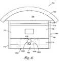
- FIG. 15is a top view of another embodiment of a case of the present invention that uses a cam for clamping a circuit card within the case.
- FIG. 16is a top view of an embodiment of a case of the present invention that has a frame and that uses cams for clamping several circuit cards within the frame.
- FIG. 17is an enlarged view of region 1675 of FIG. 16 .
- FIG. 18is a top view of an embodiment of a case of the present invention that has a pair of frames and that uses cams for clamping several circuit cards within the frames.
- FIG. 19is an exploded isometric view of an embodiment of a case of the present invention that has a pair of frames and that uses resilient elements for clamping several circuit cards within the frames.
- FIG. 20is an isometric view illustrating an embodiment of a case positioned within a housing.
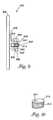
- FIG. 1shows an environmentally protected housing 100 according to the teachings of the present invention.
- Housing 100has several cases 102 1 to 102 N that are thermally coupled to the interior surface of wall 104 of housing 100 .
- Each case 102 1 to 102 Nis adapted to receive either a single circuit card, such as circuit card 106 , or a pair of circuit cards, such as circuit cards 108 a and 108 b.
- FIG. 2is an enlarged view of a circuit card, such as circuit card 106 , 108 a , or 108 b .
- circuit card 106 , 108 a , or 108 bincludes a thermally conducting case 110 that encloses circuit board 112 .
- Circuit board 112includes heat-dissipating components 114 that are frequently thermally coupled to thermally conducting case 110 by a thermal interface material 116 .
- FIG. 3is an enlarged top view of a case 102 containing a pair of circuit cards 108 a and 108 b .
- Case 102has end walls 118 and 120 , sidewalls 122 and 124 , and partition 126 that are typically fabricated from a thermally conducting material such as aluminum, copper, brass, bronze, or the like.
- Case 102is thermally coupled at end wall 118 to the interior surface of wall 104 of housing 100 by a heat-sink device 128 that conforms to the contour of the interior surface of wall 104 .
- heat-sink device 128is a solid block of material having thermal properties suitable for heat sinks, e.g., copper, aluminum, brass, bronze, or the like.
- circuit cards 108 a and 108 bNormally, relatively intimate thermal contact exists between circuit cards 108 a and 108 b and sidewalls 122 and 124 , enabling a portion of the heat dissipated by circuit cards 108 a and 108 b to be transferred to sidewalls 122 and 124 . This portion of the heat is then conducted through sidewalls 122 and 124 into heat-sink device 128 .
- gaps 130 and 132respectively exist between circuit cards 108 a and 108 b and partition 126
- gaps 134 and 136respectively exist between circuit cards 108 a and 108 b and end walls 118 and 120 , as shown in FIG. 3 .
- Another portion of the heat dissipated by circuit card 108 ais conducted and radiated to partition 126 and end wall 118 across the gaps 130 and 134 , respectively.
- Another portion of the heat dissipated by circuit card 108 bis conducted and radiated to partition 126 and end wall 120 across the gaps 132 and 136 , respectively.
- Heat conducted and radiated to end wall 118is conducted through end wall 118 into heat-sink device 128 .
- Heat conducted and radiated to partition 126 and end wall 120is respectively conducted through partition 126 and end wall 120 into sidewalls 122 and 124 , which conduct the heat to heat-sink device 128 .
- circuit cards 108 a and 108 bUnfortunately, the respective gaps produce relatively large thermal resistances and severely limit the total heat transfer from circuit cards 108 a and 108 b to case 102 . In many instances, this results in thermal failure of circuit cards 108 a and 108 b.
- Embodiments of the present inventionprovide cases, or receptacles, that clamp circuit cards within them to improve the thermal contact between the circuit cards and the cases. This substantially increases the heat transfer from circuit cards relative to the heat transfer from circuit cards that occurs when the circuit cards are not clamped within the receptacles, thus reducing the risk of thermal failure.
- Case 400illustrated in FIGS. 4–6 , is one embodiment of the present invention.
- FIG. 4is a top view of case 400
- FIG. 5a side view taken along the line 5 — 5 in FIG. 4
- FIG. 6a view taken along the line 6 — 6 of FIG. 4 .
- Embodiments of the present inventionprovide cases that clamp circuit cards within them to improve the thermal contact between the circuit cards and the cases.
- Case 400is used to confine circuit cards, e.g., circuit cards 408 a and 408 b to particular locations within an environmentally protected housing, e.g., environmentally protected housing 401 .
- circuit cards 408 a and 408 bare similar to circuit cards 108 a and 108 b and environmentally protected housing 401 is similar to housing 100 .
- case 400confines circuit cards 408 a and 408 b to a location adjacent a wall 402 of environmentally protected housing 401 .
- a heat-sink devicesuch as heat-sink device 403 , thermally couples case 400 to an interior surface of wall 402 .
- heat-sink device 403is a solid block of material having thermal properties suitable for heat sinks, e.g., copper, aluminum, brass, bronze, or the like.
- Case 400has end walls 404 and 406 , sidewalls 409 and 410 , and partition 412 .
- End walls 404 and 406 , sidewalls 409 and 410 , and partition 412are fabricated from any thermally conducting material, such as aluminum, copper, brass, bronze, or the like.
- Partition 412divides case 400 into slots 414 and 416 that respectively contain circuit cards 408 a and 408 b.
- Partition 412in one embodiment, is in slidable contact with sidewalls 409 and 410 and can slide toward end walls 404 and 406 , respectively.
- Circuit cards 408 a and 408 bin another embodiment, are in slidable contact with sidewalls 409 and 410 and can slide toward end walls 404 and 406 , respectively.
- thermally conducting greaseis disposed between partition 412 and sidewalls 409 and 410 and/or between circuit cards 408 a and 408 b and sidewalls 409 and 410 .
- the thermally conducting greaseincreases the thermal contact, and thus the heat transfer, between the partition 412 and sidewalls 409 and 410 and/or between circuit cards 408 a and 408 b and sidewalls 409 and 410 .
- gaps 418 and 420respectively exist between circuit cards 408 a and 408 b and partition 412 and gaps 422 and 424 respectively exist between circuit cards 408 a and 408 b and end walls 404 and 406 , as shown in FIG. 4 .
- Case 400includes wedge 428 insertable into gap 424 .
- Wedge 428in one embodiment, is fabricated from nylon, plastic, metal, or the like.
- wedge 428has a tab 430 , and in other embodiments, an aperture 432 passes through tab 430 , as shown in FIGS. 4–6 .
- Tab 430 and aperture 432facilitate insertion and removal of wedge 428 respectively into and from gap 424 .
- Wedge 428is pressed into gap 424 , causing wedge 428 to engage and to exert a force on circuit card 408 b .
- the forceslides circuit card 408 b into contact with partition 412 .
- Circuit card 408 bexerts a force on partition 412 that slides partition 412 into contact with circuit card 408 a .
- Partition 412exerts a force on circuit card 408 a that slides circuit card 408 a , in one embodiment, into contact with end wall 404 . This respectively closes gaps 420 , 418 , and 422 and clamps circuit card 408 a , partition 412 , circuit card 408 b , and end wall 404 in direct thermal contact.
- Direct thermal contact between partition 412 and circuit cards 408 a and 408 bsubstantially increases the heat transfer from circuit cards 408 a and 408 b to partition 412 relative to the heat transfer that occurs if gaps 418 and 420 are present.
- direct thermal contact between end wall 404 and circuit card 408 asubstantially increases the heat transfer from circuit card 408 a to end wall 404 relative to the heat transfer that occurs if gap 422 is present. Consequently, this increases the total heat transfer from circuit cards 408 a and 408 b to case 400 , reducing the risk of thermal failure.
- FIG. 7shows case 700 , another embodiment of the present invention.
- Case 700is used to a confine circuit card, e.g., circuit card 706 , to a particular location with in an environmentally protected housing, e.g., environmentally protected housing 701 .
- circuit card 706is similar to circuit card 106 and environmentally protected housing 701 is similar to housing 100 .
- case 700confines circuit card 706 to a location adjacent a wall 702 of environmentally protected housing 701 .
- a heat-sink devicesuch as heat-sink device 703 , thermally couples case 700 to an interior surface of wall 702 .
- Heat-sink device 703in one embodiment, is a solid block of material having thermal properties suitable for heat sinks, e.g., copper, aluminum, brass, bronze, or the like.
- Case 700has end walls 704 and 705 and sidewalls 708 and 710 .
- end walls 704 and 705 and sidewalls 708 and 710are fabricated from any thermally conducting material, such as aluminum, copper, brass, bronze, or the like.
- Case 700defines a slot 712 that receives a circuit card 706 .
- Circuit card 706in one embodiment, is in slidable contact with sidewalls 708 and 710 and can slide toward end walls 704 and 705 , respectively.
- thermally conducting greaseis disposed between circuit card 706 and sidewalls 708 and 710 . When circuit card 706 is inserted into slot 712 , gaps 714 and 716 respectively exist between circuit card 706 and end walls 704 and 705 .
- Case 700includes wedge 728 .
- Wedge 728is pressed into gap 716 , causing wedge 728 to engage and to exert a force on circuit card 706 .
- the forcein one embodiment, slides circuit card 706 into direct contact with end wall 704 , thereby closing gap 714 to clamp circuit card 706 and end wall 704 in direct thermal contact.
- wedge 728is as described for wedge 428 above.
- FIG. 8illustrates case 800 , another embodiment of the present invention. Elements that are common to FIGS. 4 and 8 are numbered as in FIG. 4 and are as described above. Case 800 includes a cam 810 that is disposed within gap 424 between end wall 406 and circuit card 408 b.
- Cam 810in one embodiment, is rotated from position 802 to position 804 so that a portion of cam 810 engages and exerts a force on circuit card 408 b .
- the forceslides circuit card 408 b into contact with partition 412 .
- Circuit card 408 bexerts a force on partition 412 that slides partition 412 into contact with circuit card 408 a .
- partition 412exerts a force on circuit card 408 a that slides circuit card 408 a into contact with end wall 404 . This respectively closes gaps 420 , 418 , and 422 and clamps circuit card 408 a , partition 412 , circuit card 408 b , and end wall 404 in direct thermal contact.
- Cam 810in one embodiment, is fabricated from metal, e.g., steel or aluminum, plastic, or the like.
- serrations 812are distributed over the curved surface of cam 810 , as shown in FIG. 10 , which is the surface that bears against circuit card 108 b .
- serrations 812are rubber and are molded onto cam 410 . Serrations 812 improve the contact resistance between cam 810 and circuit card 408 b and facilitate the clamping of circuit card 408 a , partition 412 , circuit card 408 b between cam 810 and end wall 404 .
- cam 810has aperture 814 passing through it for receiving a shaft, such as shaft 817 shown in FIG. 9 .
- FIG. 9is a side view of region 850 in FIG. 8 corresponding to one embodiment of case 800 .
- cam 810is rotatably attached to end wall 406 using a bracket 816 and a shaft 817 .
- Bracket 816includes protrusions 818 and 820 , respectively having apertures 824 and 826 passing therethrough.
- Cam 810is rotatably attached to end wall 406 by positioning cam 810 between protrusions 818 and 820 to align aperture 814 of cam 810 with apertures 824 and 826 and passing shaft 817 through apertures 824 , 814 , and 826 .
- Cam 810rotates about the longitudinal axis of shaft 817 and moves relative to protrusions 818 and 820 of bracket 816 .
- Bracket 816in one embodiment, is fabricated from metal, e.g., steel or aluminum, plastic, or the like and is fixed to end wall 406 by welding, gluing, bolting, or the like.
- cam 810is secured to shaft 817 using cap screws, set screws, an interference fit, or the like.
- Shaft 817in one embodiment, is fabricated from metal, e.g., steel, aluminum, or the like, plastic, or the like.
- Shaft 817in one embodiment, has a head 828 at one of its ends that is hexagonal, as shown in FIG. 8 , square, slotted, Phillips, Allen, or the like.
- a nut 830 that is hexagonal or squareis threaded onto shaft 817 at end 832 of shaft 817 . To rotate cam 810 , a torque is applied to head 828 using an appropriate wrench, screwdriver, or the like.
- FIG. 11is a side view of region 850 in FIG. 8 corresponding to another embodiment of case 800 .
- the embodiment of FIG. 11includes two cams 1010 that are rotatably attached to end wall 406 in tandem using a bracket 1016 for each cam 1010 and shaft 1017 that passes through the respective brackets 1016 and cams 1010 .
- bracket 1016 and cams 1010are as described above for bracket 816 and cam 810 .
- Shaft 1017in one embodiment, has a head 1028 at one of its ends that is hexagonal, as shown in FIG. 11 , square, slotted, Phillips, Allen, or the like.
- a nut 1030 that is hexagonal or squareis threaded onto shaft 1017 at end 1032 .
- Cams 1010are rotated into engagement with circuit card 408 b by applying a torque to head 1028 using an appropriate wrench, screwdriver, or the like.
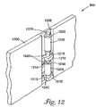
- FIG. 12is an isometric view of region 850 in FIG. 8 corresponding to yet another embodiment of case 800 .
- FIG. 13is a side view of FIG. 12
- FIG. 14illustrates the embodiment of FIG. 12 in operation.
- end wall 1206replaces end wall 406 and resilient elements 1202 and 1204 replace cam 810 .
- End wall 1206includes recess 1208 .
- a bracket 1210 and a nut 1212are disposed within recess 1208 and are respectively fastened to wall 1206 using fasteners 1214 and 1216 , as shown in FIGS. 12 and 13 .
- Bracket 1210 and nut 1212are fabricated from metal, such as steel or aluminum, plastic, or the like.
- Fasteners 1214 and 1216in one embodiment, are screws or bolts.
- bracket 1210 and nut 1212in other embodiments, are fastened to end wall 1206 by welding, gluing, or the like.
- bracket 1210 and nut 1212are fastened to a wall with no recess, such as end wall 406 .
- Bracket 1210has an aperture 1218 passing through it, as shown in FIGS. 12 and 13 .
- a sleeve 1220passes through aperture 1218 and is slidable within aperture 1218 .
- a shaft 1222passes through sleeve 1220 and is movable therein.
- An end 1224 of shaft 1222is threaded into nut 1212 .
- Shaft 1222in one embodiment, is fabricated from metal, e.g., steel, aluminum, or the like, plastic, or the like.
- Shaft 1222in one embodiment, has a head 1226 at an end opposite end 1224 that is hexagonal, as shown in FIGS. 12 and 13 , square, slotted, Phillips, Allen, or the like.
- shaft 1222sequentially passes through a washer 1228 , an aperture 1230 in resilient element 1202 , a washer 1234 , sleeve 1220 , a washer 1236 , an aperture 1238 in resilient element 1204 , and a washer 1242 and threads into nut 1212 , as shown in FIG. 13 .
- Resilient element 1202is sandwiched between washers 1228 and 1234
- resilient element 1204is sandwiched between washers 1236 and 1242 .
- Washers 1234 and 1236respectively abut sleeve 1220 at ends 1244 and 1246 of sleeve 1220
- washers 1228 and 1242respectively abut head 1226 of shaft 1222 and nut 1212 .
- Shaft 1222is movable within washer 1228 , aperture 1230 of resilient element 1202 , washer 1234 , washer 1236 , aperture 1238 of resilient element 1204 , and washer 1242 .
- Resilient elements 1202 and 1204are elastomers, e.g., polyvinyl, rubber, or the like.
- Washers 1228 , 1234 , 1236 , and 1242in one embodiment, are metal, e.g., aluminum or steel, plastic, or the like and are circular, as shown in FIG. 12 , square, etc.
- a torqueis applied to head 1226 of shaft 1222 using an appropriate wrench, screwdriver, or the like to thread shaft 1222 into nut 1212 , causing shaft 1222 to move axially into nut 1212 .
- resilient elements 1202 and 1204bulge radially, resilient elements 1202 and 1204 engage circuit card 408 b to exert a force on circuit card 408 b , as shown in FIG. 14 .
- This forcecloses gaps 420 , 418 , and 422 and clamps circuit card 408 a , partition 412 , circuit card 408 b , and end wall 404 in direct thermal contact, as described above.
- head 1226 of shaft 1222exerts an axial force on washer 1228 , which in turn exerts an axial force on resilient element 1202 .
- a portion of the axial force exerted on resilient element 1202compresses resilient element 1202 axially, causing resilient element 1202 to bulge in generally the radial direction, as shown in FIG. 14 .
- Another portion of the axial force exerted on resilient element 1202is transmitted to washer 1234 , which in turn exerts an axial force on end 1244 of sleeve 1220 .
- the axial force exerted on sleeve 1220slides sleeve 1220 relative to bracket 1210 within aperture 1218 of bracket 1210 .
- FIG. 15illustrates case 1500 , another embodiment of the present invention. Elements that are common to FIGS. 15 and 7 are numbered as in FIG. 7 and are as described above.
- Cam 1510is rotated from a position 1520 to a position 1530 , as shown in FIG. 15 , so that a portion of cam 1510 engages circuit card 706 to exert a force on circuit card 706 .
- the forcein one embodiment, slides circuit card 706 into direct contact with end wall 704 , thereby closing gap 714 to clamp circuit card 706 and end wall 704 in direct thermal contact.
- region 1550 of FIG. 15is as described for region 850 of FIG. 8 above for the embodiment of case 800 shown in FIGS. 9 and 10
- cam 1510is as described for cam 810
- region 1550 of FIG. 15is as described for region 850 of FIG. 8 above for the embodiment of case 800 shown in FIG. 11
- a pair of cams in tandemengages circuit card 706 to exert a force on circuit card 706
- region 1550 of FIG. 15is as described for region 850 of FIG. 8 above for the embodiment of case 800 shown in FIGS. 12–14 , and a pair of resilient elements engages circuit card 706 to exert a force on circuit card 706 .
- FIG. 16illustrates receptacle 1600 , another embodiment of the present invention.
- Receptacle 1600includes sidewalls 1602 and 1604 and end walls 1606 and 1607 that are fabricated from materials having suitable thermal and structural properties, such as aluminum, copper, brass, bronze, or the like.
- Receptacle 1600includes a frame 1608 divided into sub-frames 1608 1 and 1608 2 by partition 1610 .
- Sub-frame 1608 2 and partition 1610are in slidable contact with sidewalls 1602 and 1604 .
- Sub-frames 1608 1 and 1608 2are respectively partitioned into an array of slots having slots 1620 1 to 1620 N by partitions 1612 1 to 1612 N that are perpendicular to partition 1610 , as shown in FIG. 16 .
- Each slot of slots 1620 1 to 1620 Nrespectively confines one of circuit cards 1622 1 to 1622 N to a particular location within case 1600 .
- Frame 1608is fabricated from materials having suitable thermal and structural properties, such as aluminum, copper, brass, bronze, or the like.
- Circuit cards 1622 1 to 1622 Nin one embodiment, are as described above for circuit card 106 108 a , or 108 b.
- a gap 1624separates frame 1608 from end wall 1606 .
- Cams 1611are disposed within gap 1624 .
- Cams 1611are rotated into and out of engagement with frame 1608 .
- cams 1611engage frame 1608 , cams 1611 respectively exert a force on frame 1608 , and, in particular, sub-frame 1608 2 .
- regions 1650 of FIG. 16are as described for region 850 of FIG. 8 above for the embodiment of case 800 shown in FIGS. 9 and 10 , and cams 1611 are as described for cam 810 .
- regions 1650 of FIG. 16are as described for region 850 of FIG. 8 above for the embodiment of case 800 shown in FIG. 11 , and two tandem pairs of cams engage frame 1608 to exert a force on frame 1608 .
- regions 1650 of FIG. 16are as described for region 850 of FIG. 8 above for the embodiment of case 800 shown in FIGS. 12–14 , and two pairs of resilient elements engage frame 1608 to exert a force on frame 1608 .
- a single region 1650 midway between sidewalls 1602 and 1604replaces regions 1650 , and a single cam, a tandem pair of cams, or a pair of resilient elements are located midway between sidewalls 1602 and 1604 .
- FIG. 17is an enlarged view of region 1675 of FIG. 16 and corresponds to when a force, as represented by arrow 1750 , is initially exerted on sub-frame 1608 2 , for example, by cam 1611 .
- FIG. 17shows, in one embodiment, that the circuit cards 1622 1 to 1622 N , e.g., circuit cards 1622 1 and 1622 N , extend beyond sub-frames 1608 1 and 1608 2 and partitions 1612 1 to 1612 N , e.g., 1612 1 and 1612 N , by a distance 1702 .
- the distance 1702is substantially zero, and circuit cards 1622 1 to 1622 N are substantially flush with sub-frames 1608 1 and 1608 2 and partitions 1612 1 to 1612 N . Moreover, circuit cards 1622 1 to 1622 N , e.g., circuit cards 1622 1 and 1622 N , are each separated from partition 1610 by a gap 1704 .
- circuit cards 1622 1 to 1622 N contained in the slots of sub-frame 1608 2are clamped between sub-frame 1608 2 and partition 1610
- circuit cards of circuit cards 1622 1 to 1622 N contained in the slots of sub-frame 1608 1are clamped between and partition 1610 and sub-frame 1608 1 . Therefore, circuit cards 1622 1 to 1622 N are clamped in direct contact with frame 1608 , which is in contact with end walls 1606 and 1607 and sidewalls 1602 and 1604 of case 1600 .
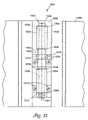
- FIG. 18illustrates receptacle 1800 , another embodiment of the present invention.
- Receptacle 1800includes sidewalls 1802 and 1804 and end walls 1806 and 1807 that are fabricated from materials having suitable thermal and structural properties, such as aluminum, copper, brass, bronze, or the like.
- Receptacle 1800includes frames 1808 and 1809 , respectively divided into sub-frames 1808 1 and 1808 2 by partition 1810 and sub-frames 1809 1 and 1809 2 by partition 1811 .
- Sub-frames 1808 2 and 1809 2 and partitions 1810 and 1811in one embodiment, are in slidable contact with sidewalls 1802 and 1804 .
- Sub-frames 1808 1 and 1808 2are partitioned into an array of slots having slots 1820 1 to 1820 N by partitions 1812 1 to 1812 N that are perpendicular to partition 1810 , as shown in FIG. 18 .
- Sub-frames 1809 1 and 1809 2are partitioned into an array of slots having slots 1821 1 to 1821 N by partitions 1813 1 to 1813 N that are perpendicular to partition 1811 , as shown in FIG. 18 .
- Each slot of slots 1820 1 to 1820 Nrespectively confines one of circuit cards 1822 1 to 1822 N to a particular location within frame 1808 .
- Each slot of slots 1821 1 to 1821 Nrespectively confines one of circuit cards 1823 1 to 1823 N to a particular location within frame 1809 .
- Frames 1808 and 1809are fabricated from materials having suitable thermal and structural properties, such as aluminum, copper, brass, bronze, or the like.
- Circuit cards 1822 1 to 1822 N and circuit cards 1823 1 to 1823 Nare as described above for circuit card 106 , 108 a , or 108 b.
- Frames 1808 and 1809are separated by a gap 1824 that contains cams 1825 .
- Each cam 1825is rotatably attached to frame 1808 , and, in particular, to sub-frame 1808 2 of frame 1808 .
- Cams 1825are rotated into and out of engagement with frame 1809 , and, in particular, into and out of engagement with sub-frame 1809 2 of frame 1809 .
- cams 1825engage sub-frame 1809 2
- cams 1825respectively exert a force on sub-frame 1809 2 producing a reaction force that is exerted on sub-frame 1808 2 .
- a forceis exerted on both frames 1809 and 1808 , and, in particular, on both sub-frames 1809 2 and 1808 2 .
- the regions 1830 and 1840are as described for region 1675 in FIG. 16 .
- a forceis exerted on both sub-frames 1809 2 and 1808 2 , e.g., by each of cams 1825 , the force slides sub-frame 1808 2 so that the circuit cards of circuit cards 1822 1 to 1822 N that are in sub-frame 1808 2 contact partition 1810 and exert a force on partition 1810 .
- the force exerted on partition 1810slides partition 1810 into contact with the circuit cards of circuit cards 1822 1 to 1822 N that are in sub-frame 1808 1 .
- circuit cards of circuit cards 1822 1 to 1822 N contained in the slots of sub-frame 1808 2are clamped between sub-frame 1808 2 and partition 1810
- circuit cards of circuit cards 1822 1 to 1822 N contained in the slots of sub-frame 1808 1are clamped between and partition 1810 and sub-frame 1808 1 .
- the forcealso slides sub-frame 1809 2 so that the circuit cards of circuit cards 1823 1 to 1823 N that are in sub-frame 1809 2 contact partition 1811 and exert a force on partition 1811 .
- the force exerted on partition 1811slides partition 1811 into contact with the circuit cards of circuit cards 1823 1 to 1823 N that are in sub-frame 1809 1 .
- the circuit cards of circuit cards 1823 1 to 1823 N contained in the slots of sub-frame 1809 2are clamped between sub-frame 1809 2 and partition 1811
- the circuit cards of circuit cards 1823 1 to 1823 N contained in the slots of sub-frame 1809 1are clamped between and partition 1811 and sub-frame 1809 1 .
- regions 1850 of FIG. 18are as described for region 850 of FIG. 8 above for the embodiment of case 800 shown in FIGS. 9 and 10 , and cams 1825 are as described for cam 810 .
- regions 1850 of FIG. 18are as described for region 850 of FIG. 8 above for the embodiment of case 800 shown in FIG. 11 , and two tandem pairs of cams are attached to frame 1808 and are rotated to engage frame 1809 to exert a force on both frames 1808 and 1809 .
- regions 1850 of FIG. 18are as described for region 850 of FIG. 8 above for the embodiment of case 800 shown in FIGS.
- a single region 1850 midway between sidewalls 1802 and 1804replaces regions 1850 , and a single cam, a tandem pair of cams, or a pair of resilient elements are located midway between sidewalls 1802 and 1804 .
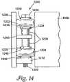
- region 1875 of FIG. 18is as shown in the exploded view of FIG. 19 .
- sub-frame portions 1908 2 and 1909 2respectively replace the portions of sub-frames 1808 2 and 1809 2 contained within region 1875
- gap 1924replaces gap 1824 .
- Sub-frame portions 1908 2 and 1909 2respectively have recesses 1910 and 1911 , with the recess 1910 having resilient elements 1902 and 1904 disposed therein.
- resilient elements 1902 and 1904are as described above in conjunction with FIGS. 12–14 .
- Resilient elements 1902 and 1904are compressed axially between head 1918 of shaft 1920 and nut 1922 when a torque is applied to head 1918 to thread shaft 1920 axially into nut 1922 .
- Thiscauses resilient elements 1902 and 1904 to bulge in generally the radial direction.
- resilient elements 1902 and 1904bulge generally radially, resilient elements 1902 and 1904 engage sub-frame portion 1909 2 within recess 1911 .
- resilient elements 1902 and 1904respectively exert a force on sub-frame portion 1909 2 producing a reaction force that is exerted on sub-frame portion 1908 2 . In this way, a force is exerted on both sub-frame portions 1908 2 and 1909 2 .
- a pair of cases 1800is located within a housing, such as housing 2000 shown in FIG. 20 .
- Housing 2000has two compartments 2002 that are closed by covers 2004 .
- Each of compartments 2002receives a case 1800 , as shown in FIG. 20 , which, in one embodiment, is thermally coupled to housing 2000 , as described in U.S. patent application Ser. No. 09/804,129, entitled MECHANICAL HOUSING, which application is incorporated herein by reference.
- Embodiments of the present inventionhave been described.
- the embodimentsprovide cases that clamp circuit cards within them to improve the thermal contact between the circuit cards and the cases, thereby reducing the risk of thermal failure.
- cam 810is portrayed in the accompanying figures as being oval, cam 810 can also be circular, elliptical, or any suitable shape.
- serrations 412as shown in FIG. 10 , can be eliminated from the curved surface of cam 810 , or serrations 412 can be of a material other than rubber, such as plastic, metal, or the like.
- resilient elements 1202 and 1204are shown to be hollow cylinders in FIG.
- resilient elements 1202 and 1204can have other geometries, such as cubes having apertures passing through them.
- cams 1611are rotatably attached to end wall 1606 , as shown in FIG. 16 , and are rotatable into engagement with frame 1608
- cams 1611can be rotatably attached to frame 1608 and can be rotated into engagement with end wall 1606 .
- cams 1825are rotatably attached to frame 1808 , as shown in FIG. 18 , and are rotatable into engagement with frame 1809
- cams 1825can be rotatably attached to frame 1809 and can be rotatable into engagement with frame 1808 .
Landscapes
- Engineering & Computer Science (AREA)
- Microelectronics & Electronic Packaging (AREA)
- Coupling Device And Connection With Printed Circuit (AREA)
- Casings For Electric Apparatus (AREA)
- Cooling Or The Like Of Electrical Apparatus (AREA)
Abstract
Description
Claims (14)
Priority Applications (1)
| Application Number | Priority Date | Filing Date | Title |
|---|---|---|---|
| US11/099,344US6992249B2 (en) | 2001-07-31 | 2005-04-05 | Clamping receptacle |
Applications Claiming Priority (2)
| Application Number | Priority Date | Filing Date | Title |
|---|---|---|---|
| US09/919,006US6897377B2 (en) | 2001-07-31 | 2001-07-31 | Clamping receptacle |
| US11/099,344US6992249B2 (en) | 2001-07-31 | 2005-04-05 | Clamping receptacle |
Related Parent Applications (1)
| Application Number | Title | Priority Date | Filing Date |
|---|---|---|---|
| US09/919,006DivisionUS6897377B2 (en) | 2001-07-31 | 2001-07-31 | Clamping receptacle |
Publications (2)
| Publication Number | Publication Date |
|---|---|
| US20050191884A1 US20050191884A1 (en) | 2005-09-01 |
| US6992249B2true US6992249B2 (en) | 2006-01-31 |
Family
ID=25441331
Family Applications (2)
| Application Number | Title | Priority Date | Filing Date |
|---|---|---|---|
| US09/919,006Expired - LifetimeUS6897377B2 (en) | 2001-07-31 | 2001-07-31 | Clamping receptacle |
| US11/099,344Expired - LifetimeUS6992249B2 (en) | 2001-07-31 | 2005-04-05 | Clamping receptacle |
Family Applications Before (1)
| Application Number | Title | Priority Date | Filing Date |
|---|---|---|---|
| US09/919,006Expired - LifetimeUS6897377B2 (en) | 2001-07-31 | 2001-07-31 | Clamping receptacle |
Country Status (3)
| Country | Link |
|---|---|
| US (2) | US6897377B2 (en) |
| CA (1) | CA2456019C (en) |
| WO (1) | WO2003013202A2 (en) |
Cited By (5)
| Publication number | Priority date | Publication date | Assignee | Title |
|---|---|---|---|---|
| US20050170681A1 (en)* | 2001-07-31 | 2005-08-04 | Adc Telecommunications, Inc. | Clamping case |
| US7450382B1 (en) | 2007-05-15 | 2008-11-11 | Adc Telecommunications, Inc. | Apparatus for enclosing electronic components |
| US20080278915A1 (en)* | 2007-05-10 | 2008-11-13 | Adc Telecommunications, Inc. | Chassis mounted heat sink system |
| US20080291627A1 (en)* | 2007-05-23 | 2008-11-27 | Adc Telecommunications, Inc. | Apparatus for enclosing electronic components used in telecommunication systems |
| USD835040S1 (en) | 2016-09-09 | 2018-12-04 | Corning Research & Development Corporation | 1×4 distribution point unit |
Families Citing this family (10)
| Publication number | Priority date | Publication date | Assignee | Title |
|---|---|---|---|---|
| US6897377B2 (en)* | 2001-07-31 | 2005-05-24 | Adc Telecommunications, Inc. | Clamping receptacle |
| US7658630B2 (en)* | 2005-04-18 | 2010-02-09 | Hewlett-Packard Development Company, L.P. | System and method for connecting electronic components |
| USD581927S1 (en)* | 2006-12-26 | 2008-12-02 | Sony Corporation | Arithmetic and control unit |
| USD598018S1 (en)* | 2006-12-26 | 2009-08-11 | Sony Corporation | Server |
| US20090014166A1 (en)* | 2007-07-09 | 2009-01-15 | Baker Hughes Incorporated | Shock absorption for a logging instrument |
| USD580358S1 (en)* | 2007-12-14 | 2008-11-11 | Jack Gershfeld | Interconnect enclosure for computer and audio visual equipment mountable under a table top |
| KR101358408B1 (en)* | 2008-07-04 | 2014-02-04 | 삼성전자주식회사 | Docking station |
| US10327357B2 (en)* | 2014-09-18 | 2019-06-18 | Artesyn Embedded Computing, Inc. | Thermal conduction to a cylindrical shaft |
| US9320181B1 (en) | 2014-11-14 | 2016-04-19 | General Electric Company | System and method for dissipating thermal energy away from electronic components in a rotatable shaft |
| US10082843B2 (en)* | 2015-04-16 | 2018-09-25 | Hewlett-Packard Development Company, L.P. | Adjustable expansion slots |
Citations (97)
| Publication number | Priority date | Publication date | Assignee | Title |
|---|---|---|---|---|
| US2737579A (en) | 1951-04-06 | 1956-03-06 | Acf Ind Inc | Amplifier assembly |
| US2796559A (en) | 1952-09-11 | 1957-06-18 | Bendix Aviat Corp | Electrical apparatus |
| US2833966A (en) | 1956-06-13 | 1958-05-06 | George N Goodier | Heat conducting tube mount |
| US2876277A (en) | 1954-12-29 | 1959-03-03 | Ibm | Electrical component mounting apparatus |
| US3087095A (en) | 1959-12-28 | 1963-04-23 | Bell Telephone Labor Inc | Cushion mounting for electrical apparatus |
| US3135321A (en) | 1960-03-07 | 1964-06-02 | Trane Co | Heat exchanger |
| US3366171A (en) | 1966-07-14 | 1968-01-30 | Bbc Brown Boveri & Cie | Heat sink for semi-conductor elements |
| US3467891A (en) | 1967-10-03 | 1969-09-16 | Gen Electric | Combination electrical,mechanical,and thermal connector assembly |
| US3487267A (en) | 1968-01-02 | 1969-12-30 | Jerrold Electronics Corp | Thermally conducting transistor support arms |
| US3697929A (en) | 1971-01-18 | 1972-10-10 | Bunker Ramo | Controlled insertion force receptacle for flat circuit bearing elements |
| US3767974A (en) | 1972-01-03 | 1973-10-23 | Cogar Corp | Insertion and extraction lever for printed circuit cards |
| US3809798A (en) | 1972-09-06 | 1974-05-07 | H Simon | Angle type feedthrough cable clamp |
| US3997819A (en) | 1974-09-09 | 1976-12-14 | Siemens Aktiengesellschaft | Housing for electrical communications and measuring devices |
| US4172212A (en) | 1978-07-24 | 1979-10-23 | International Telephone And Telegraph Corporation | Submarine housing for submarine cable system repeater components or the like |
| US4184539A (en) | 1978-07-10 | 1980-01-22 | The United States Of America As Represented By The Secretary Of The Navy | Electronic card mount and heat transfer assembly for underwater vehicles |
| US4259843A (en) | 1979-10-09 | 1981-04-07 | Cromemco Inc. | Isolation chamber for electronic devices |
| US4301494A (en) | 1979-09-28 | 1981-11-17 | Wescom, Inc. | Printed circuit board faceplate assembly |
| JPS58634A (en) | 1981-06-20 | 1983-01-05 | Yamaha Motor Co Ltd | Dry clutch |
| JPS58105187A (en) | 1981-12-17 | 1983-06-22 | 佐瀬 英三 | Flour mill model harnessing water wheel |
| US4449576A (en) | 1980-11-25 | 1984-05-22 | Kabel- Und Metallwerke | Heat-producing elements with heat pipes |
| JPS6026936A (en) | 1983-07-25 | 1985-02-09 | Olympus Optical Co Ltd | Control device for exposure |
| JPS6079834A (en) | 1983-10-07 | 1985-05-07 | Nec Corp | Structure of optical submarine repeater unit |
| US4528615A (en) | 1983-05-13 | 1985-07-09 | At&T Bell Laboratories | Repeater housing and circuit mounting structure |
| US4547833A (en) | 1983-12-23 | 1985-10-15 | Schlumberger Technology Corporation | High density electronics packaging system for hostile environment |
| US4559790A (en) | 1982-10-18 | 1985-12-24 | General Electric Company | Apparatus for maintaining electronic equipment and the like at low temperatures in hot ambient environments |
| US4564061A (en) | 1981-12-18 | 1986-01-14 | Ant Nachrichtentechnik Gmbh | Cooling system for communications devices with high power losses |
| JPS6267936A (en) | 1985-09-19 | 1987-03-27 | Fujitsu Ltd | wireless communication device |
| US4656559A (en) | 1984-05-10 | 1987-04-07 | Ultima Electronics Ltd. | Holder and heat sink for electronic components |
| JPS6279404A (en) | 1985-10-03 | 1987-04-11 | Nec Corp | Optical submarine repeater enclosure |
| US4662002A (en) | 1984-01-19 | 1987-04-28 | Standard Telephones And Cables Public Limited Company | Optical repeaters |
| US4679250A (en) | 1984-01-19 | 1987-07-07 | Standard Telephones And Cables Plc | Optical repeaters |
| GB2193552A (en) | 1986-08-08 | 1988-02-10 | Stc Plc | Repeater housing |
| US4777561A (en) | 1985-03-26 | 1988-10-11 | Hughes Aircraft Company | Electronic module with self-activated heat pipe |
| US4805482A (en) | 1987-08-24 | 1989-02-21 | Brunswick Corporation | Cam adjustment assembly |
| US4815913A (en) | 1987-03-20 | 1989-03-28 | Matsushita Electric Industrial Co., Ltd. | Electronic component mounting device |
| US4849858A (en) | 1986-10-20 | 1989-07-18 | Westinghouse Electric Corp. | Composite heat transfer means |
| US4858070A (en) | 1987-04-24 | 1989-08-15 | Racal Data Communications Inc. | Modular expandable housing arrangement for electronic apparatus |
| US4858068A (en) | 1986-03-21 | 1989-08-15 | Alcatel Cit | Electronic circuit housing |
| JPH024287A (en) | 1988-06-22 | 1990-01-09 | Olympus Optical Co Ltd | Display control system |
| US4909752A (en) | 1989-03-31 | 1990-03-20 | Honeywell, Inc. | Circuit card retainer |
| JPH02166798A (en) | 1988-12-21 | 1990-06-27 | Nec Corp | Heat radiation structure for communication equipment case |
| US4953058A (en) | 1989-09-01 | 1990-08-28 | General Dynamics Corporation, Space Systems Div. | Modular segment adapted to provide a passively cooled housing for heat generating electronic modules |
| US4962444A (en) | 1989-01-03 | 1990-10-09 | Sunstrand Corporation | Cold chassis for cooling electronic circuit components on an electronic board |
| US4962445A (en) | 1988-04-21 | 1990-10-09 | Societe Anonyme Dite: Alcatel Cit | Housing for submersible equipment |
| US4987978A (en) | 1989-10-10 | 1991-01-29 | Jungersen Thoger G | Wheelchair safety brakes |
| US5019939A (en) | 1989-10-24 | 1991-05-28 | Ag Communication Systems Corp. | Thermal management plate |
| US5045971A (en) | 1989-04-18 | 1991-09-03 | Mitsubishi Denki Kabushiki Kaisha | Electronic device housing with temperature management functions |
| US5048793A (en) | 1990-06-14 | 1991-09-17 | Miller Pipeline Corporation | Pipe jack |
| US5089935A (en) | 1990-02-28 | 1992-02-18 | Mitsubishi Denki Kabushiki Kaisha | Control device case |
| US5105337A (en) | 1989-12-29 | 1992-04-14 | Alcatel Cit | Housing for underwater electronic circuits |
| US5267122A (en) | 1992-06-15 | 1993-11-30 | Alcatel Network Systems, Inc. | Optical network unit |
| US5309315A (en) | 1991-08-09 | 1994-05-03 | Pulse Embedded Computer Systems, Inc. | Severe environment enclosure with thermal heat sink and EMI protection |
| US5329425A (en) | 1991-02-25 | 1994-07-12 | Alcatel N.V. | Cooling system |
| US5337218A (en) | 1992-06-02 | 1994-08-09 | International Business Machines Corporation | Circuit card interconnecting structure |
| US5398164A (en) | 1993-02-24 | 1995-03-14 | International Business Machines Corporation | Printed circuit card latching and stiffening assembly |
| US5424916A (en) | 1989-07-28 | 1995-06-13 | The Charles Stark Draper Laboratory, Inc. | Combination conductive and convective heatsink |
| US5432682A (en) | 1993-01-27 | 1995-07-11 | Raac Technologies, Inc. | AT computer card mounting bracket |
| JPH07177645A (en) | 1993-12-21 | 1995-07-14 | Nec Eng Ltd | Heat dissipating/shock absorbing structure for submarine repeater |
| JPH0865868A (en) | 1994-08-19 | 1996-03-08 | Nec Eng Ltd | Heat radiation/buffering structure of submarine repeater |
| US5519573A (en) | 1994-12-27 | 1996-05-21 | Intel Corporation | I/O riser card for motherboard in a personal computer/server |
| US5642264A (en) | 1991-04-01 | 1997-06-24 | E-Systems, Inc. | Apparatus for supporting circuit cards in slot locations |
| US5822196A (en) | 1996-06-05 | 1998-10-13 | Compaq Computer Corporation | Securing a card in an electronic device |
| US5825621A (en) | 1997-06-12 | 1998-10-20 | Harris Corporation | Closed loop cooling housing for printed circuit card-mounted, sealed heat exchanger |
| US5842514A (en) | 1997-03-05 | 1998-12-01 | Northern Telecom Limited | Electronic unit |
| US5896268A (en) | 1997-08-11 | 1999-04-20 | Abacon Telecommunications Corporation | Enclosure for high-density subscriber line modules |
| US5923531A (en) | 1997-10-14 | 1999-07-13 | International Business Machines Corporation | Enhanced circuit board arrangement for a computer |
| US5995378A (en) | 1997-12-31 | 1999-11-30 | Micron Technology, Inc. | Semiconductor device socket, assembly and methods |
| US6002588A (en) | 1997-12-04 | 1999-12-14 | Lockheed Martin Corporation | Thermally conductive vibration isolators |
| US6038129A (en) | 1998-04-28 | 2000-03-14 | Lucent Technologies Inc. | Cooling electronic apparatus |
| US6045140A (en) | 1997-07-11 | 2000-04-04 | Cummins Engine Company, Inc. | Retention gasket with cooperating cover |
| US6104611A (en) | 1995-10-05 | 2000-08-15 | Nortel Networks Corporation | Packaging system for thermally controlling the temperature of electronic equipment |
| US6118662A (en) | 1999-11-05 | 2000-09-12 | Special Product Company | Enclosure for telecommunications equipment |
| EP1041002A2 (en) | 1999-04-01 | 2000-10-04 | Negesat Di Boer Fabrizio & C. SNC | Protective casing with cooling for equipment in air, space or land vehicles |
| US6151213A (en) | 1999-05-12 | 2000-11-21 | 3Com Corporation | Ventilation and cooling control system for modular platforms |
| US6209631B1 (en) | 1999-07-23 | 2001-04-03 | Esco Electronics Corporation | Thermal management apparatus for a sealed enclosure |
| US6289678B1 (en) | 1998-12-03 | 2001-09-18 | Phoenix Group, Inc. | Environmental system for rugged disk drive |
| US6292556B1 (en) | 1997-11-06 | 2001-09-18 | Anacapa Technology, Inc. | Local loop telecommunication repeater housings employing thermal collection, transfer and distribution via solid thermal conduction |
| US6292361B1 (en) | 1999-12-20 | 2001-09-18 | Dell Usa, L.P. | Apparatus and method for mounting and cooling a system component assembly in a computer |
| US6295208B1 (en) | 1999-02-12 | 2001-09-25 | 3Com Corporation | Backplate for securing a circuit card to a computer chassis |
| US6310772B1 (en) | 1999-09-02 | 2001-10-30 | Special Product Company | Enclosure for telecommunications equipment |
| US6381146B1 (en) | 2000-09-28 | 2002-04-30 | Hewlett-Packard Company | Module removal system |
| US6396691B1 (en) | 2000-04-17 | 2002-05-28 | Circa Telecom, Usa, Inc. | Thermal cover for T1/HDSL repeater case |
| US6404637B2 (en) | 2000-02-14 | 2002-06-11 | Special Product Company | Concentrical slot telecommunications equipment enclosure |
| US6406312B1 (en) | 2001-04-25 | 2002-06-18 | Juniper Networks, Inc. | Circuit card captivation and ejection mechanism including a lever to facilitate removal of the mechanism from a housing |
| US6421252B1 (en) | 2000-11-10 | 2002-07-16 | International Business Machines Corporation | System and method for a self aligning multiple card enclosure with hot plug capability |
| US6430044B2 (en) | 2000-02-10 | 2002-08-06 | Special Product Company | Telecommunications enclosure with individual, separated card holders |
| US20020141153A1 (en) | 2001-03-27 | 2002-10-03 | Compucase Enterprise Co., Ltd. | Case for mounting slidably a data storage medium in a computer housing |
| US6493236B1 (en) | 2001-05-29 | 2002-12-10 | Sony Computer Entertainment Inc. | Electronic equipment |
| US6496385B1 (en) | 1999-09-29 | 2002-12-17 | Silicon Graphics, Inc. | Method and assembly for installation or removal of printed circuit card |
| US6587339B1 (en) | 2002-03-29 | 2003-07-01 | Thornhurst Manufacturing, Inc. | Protective pot or container |
| US6752276B2 (en)* | 2002-08-12 | 2004-06-22 | Sun Microsystems, Inc. | PCI card support |
| US6838617B2 (en)* | 2003-05-01 | 2005-01-04 | Ultratech International, Inc. | Macroencapsulation container having both releasable and permanent sealing means |
| US6856518B2 (en)* | 2003-07-14 | 2005-02-15 | Hewlett Packard Development Company, L.P. | Assembly for supporting a short printed circuit card |
| US6894907B2 (en)* | 2001-07-31 | 2005-05-17 | Adc Telecommunications, Inc. | Clamping case |
| US6897377B2 (en)* | 2001-07-31 | 2005-05-24 | Adc Telecommunications, Inc. | Clamping receptacle |
| US6934152B1 (en)* | 2003-06-27 | 2005-08-23 | Emc Corporation | Systems and methods for connecting an electronic apparatus to a backplane |
| US6937467B2 (en)* | 2003-08-27 | 2005-08-30 | Inventec Corporation | Device for fastening adapter cards at a positioning frame of computer case |
Family Cites Families (2)
| Publication number | Priority date | Publication date | Assignee | Title |
|---|---|---|---|---|
| US510223A (en)* | 1893-12-05 | Pottery-kiln | ||
| US946193A (en)* | 1907-02-18 | 1910-01-11 | Emile Bachelet | Electromagnet. |
- 2001
- 2001-07-31USUS09/919,006patent/US6897377B2/ennot_activeExpired - Lifetime
- 2002
- 2002-07-31WOPCT/US2002/024757patent/WO2003013202A2/ennot_activeApplication Discontinuation
- 2002-07-31CACA2456019Apatent/CA2456019C/ennot_activeExpired - Fee Related
- 2005
- 2005-04-05USUS11/099,344patent/US6992249B2/ennot_activeExpired - Lifetime
Patent Citations (100)
| Publication number | Priority date | Publication date | Assignee | Title |
|---|---|---|---|---|
| US2737579A (en) | 1951-04-06 | 1956-03-06 | Acf Ind Inc | Amplifier assembly |
| US2796559A (en) | 1952-09-11 | 1957-06-18 | Bendix Aviat Corp | Electrical apparatus |
| US2876277A (en) | 1954-12-29 | 1959-03-03 | Ibm | Electrical component mounting apparatus |
| US2833966A (en) | 1956-06-13 | 1958-05-06 | George N Goodier | Heat conducting tube mount |
| US3087095A (en) | 1959-12-28 | 1963-04-23 | Bell Telephone Labor Inc | Cushion mounting for electrical apparatus |
| US3135321A (en) | 1960-03-07 | 1964-06-02 | Trane Co | Heat exchanger |
| US3366171A (en) | 1966-07-14 | 1968-01-30 | Bbc Brown Boveri & Cie | Heat sink for semi-conductor elements |
| US3467891A (en) | 1967-10-03 | 1969-09-16 | Gen Electric | Combination electrical,mechanical,and thermal connector assembly |
| US3487267A (en) | 1968-01-02 | 1969-12-30 | Jerrold Electronics Corp | Thermally conducting transistor support arms |
| US3697929A (en) | 1971-01-18 | 1972-10-10 | Bunker Ramo | Controlled insertion force receptacle for flat circuit bearing elements |
| US3767974A (en) | 1972-01-03 | 1973-10-23 | Cogar Corp | Insertion and extraction lever for printed circuit cards |
| US3809798A (en) | 1972-09-06 | 1974-05-07 | H Simon | Angle type feedthrough cable clamp |
| US3997819A (en) | 1974-09-09 | 1976-12-14 | Siemens Aktiengesellschaft | Housing for electrical communications and measuring devices |
| US4184539A (en) | 1978-07-10 | 1980-01-22 | The United States Of America As Represented By The Secretary Of The Navy | Electronic card mount and heat transfer assembly for underwater vehicles |
| US4172212A (en) | 1978-07-24 | 1979-10-23 | International Telephone And Telegraph Corporation | Submarine housing for submarine cable system repeater components or the like |
| US4301494A (en) | 1979-09-28 | 1981-11-17 | Wescom, Inc. | Printed circuit board faceplate assembly |
| US4259843A (en) | 1979-10-09 | 1981-04-07 | Cromemco Inc. | Isolation chamber for electronic devices |
| US4449576A (en) | 1980-11-25 | 1984-05-22 | Kabel- Und Metallwerke | Heat-producing elements with heat pipes |
| JPS58634A (en) | 1981-06-20 | 1983-01-05 | Yamaha Motor Co Ltd | Dry clutch |
| JPS58105187A (en) | 1981-12-17 | 1983-06-22 | 佐瀬 英三 | Flour mill model harnessing water wheel |
| US4564061A (en) | 1981-12-18 | 1986-01-14 | Ant Nachrichtentechnik Gmbh | Cooling system for communications devices with high power losses |
| US4559790A (en) | 1982-10-18 | 1985-12-24 | General Electric Company | Apparatus for maintaining electronic equipment and the like at low temperatures in hot ambient environments |
| US4528615A (en) | 1983-05-13 | 1985-07-09 | At&T Bell Laboratories | Repeater housing and circuit mounting structure |
| JPS6026936A (en) | 1983-07-25 | 1985-02-09 | Olympus Optical Co Ltd | Control device for exposure |
| JPS6079834A (en) | 1983-10-07 | 1985-05-07 | Nec Corp | Structure of optical submarine repeater unit |
| US4547833A (en) | 1983-12-23 | 1985-10-15 | Schlumberger Technology Corporation | High density electronics packaging system for hostile environment |
| US4662002A (en) | 1984-01-19 | 1987-04-28 | Standard Telephones And Cables Public Limited Company | Optical repeaters |
| US4679250A (en) | 1984-01-19 | 1987-07-07 | Standard Telephones And Cables Plc | Optical repeaters |
| US4656559A (en) | 1984-05-10 | 1987-04-07 | Ultima Electronics Ltd. | Holder and heat sink for electronic components |
| US4777561A (en) | 1985-03-26 | 1988-10-11 | Hughes Aircraft Company | Electronic module with self-activated heat pipe |
| JPS6267936A (en) | 1985-09-19 | 1987-03-27 | Fujitsu Ltd | wireless communication device |
| JPS6279404A (en) | 1985-10-03 | 1987-04-11 | Nec Corp | Optical submarine repeater enclosure |
| US4858068A (en) | 1986-03-21 | 1989-08-15 | Alcatel Cit | Electronic circuit housing |
| GB2193552A (en) | 1986-08-08 | 1988-02-10 | Stc Plc | Repeater housing |
| US4849858A (en) | 1986-10-20 | 1989-07-18 | Westinghouse Electric Corp. | Composite heat transfer means |
| US4815913A (en) | 1987-03-20 | 1989-03-28 | Matsushita Electric Industrial Co., Ltd. | Electronic component mounting device |
| US4858070A (en) | 1987-04-24 | 1989-08-15 | Racal Data Communications Inc. | Modular expandable housing arrangement for electronic apparatus |
| US4805482A (en) | 1987-08-24 | 1989-02-21 | Brunswick Corporation | Cam adjustment assembly |
| US4962445A (en) | 1988-04-21 | 1990-10-09 | Societe Anonyme Dite: Alcatel Cit | Housing for submersible equipment |
| JPH024287A (en) | 1988-06-22 | 1990-01-09 | Olympus Optical Co Ltd | Display control system |
| JPH02166798A (en) | 1988-12-21 | 1990-06-27 | Nec Corp | Heat radiation structure for communication equipment case |
| US4962444A (en) | 1989-01-03 | 1990-10-09 | Sunstrand Corporation | Cold chassis for cooling electronic circuit components on an electronic board |
| US4909752A (en) | 1989-03-31 | 1990-03-20 | Honeywell, Inc. | Circuit card retainer |
| US5045971A (en) | 1989-04-18 | 1991-09-03 | Mitsubishi Denki Kabushiki Kaisha | Electronic device housing with temperature management functions |
| US5424916A (en) | 1989-07-28 | 1995-06-13 | The Charles Stark Draper Laboratory, Inc. | Combination conductive and convective heatsink |
| US4953058A (en) | 1989-09-01 | 1990-08-28 | General Dynamics Corporation, Space Systems Div. | Modular segment adapted to provide a passively cooled housing for heat generating electronic modules |
| US4987978A (en) | 1989-10-10 | 1991-01-29 | Jungersen Thoger G | Wheelchair safety brakes |
| US5019939A (en) | 1989-10-24 | 1991-05-28 | Ag Communication Systems Corp. | Thermal management plate |
| US5105337A (en) | 1989-12-29 | 1992-04-14 | Alcatel Cit | Housing for underwater electronic circuits |
| US5089935A (en) | 1990-02-28 | 1992-02-18 | Mitsubishi Denki Kabushiki Kaisha | Control device case |
| US5048793A (en) | 1990-06-14 | 1991-09-17 | Miller Pipeline Corporation | Pipe jack |
| US5329425A (en) | 1991-02-25 | 1994-07-12 | Alcatel N.V. | Cooling system |
| US5642264A (en) | 1991-04-01 | 1997-06-24 | E-Systems, Inc. | Apparatus for supporting circuit cards in slot locations |
| US5309315A (en) | 1991-08-09 | 1994-05-03 | Pulse Embedded Computer Systems, Inc. | Severe environment enclosure with thermal heat sink and EMI protection |
| US5337218A (en) | 1992-06-02 | 1994-08-09 | International Business Machines Corporation | Circuit card interconnecting structure |
| US5267122A (en) | 1992-06-15 | 1993-11-30 | Alcatel Network Systems, Inc. | Optical network unit |
| US5432682A (en) | 1993-01-27 | 1995-07-11 | Raac Technologies, Inc. | AT computer card mounting bracket |
| US5398164A (en) | 1993-02-24 | 1995-03-14 | International Business Machines Corporation | Printed circuit card latching and stiffening assembly |
| JPH07177645A (en) | 1993-12-21 | 1995-07-14 | Nec Eng Ltd | Heat dissipating/shock absorbing structure for submarine repeater |
| JPH0865868A (en) | 1994-08-19 | 1996-03-08 | Nec Eng Ltd | Heat radiation/buffering structure of submarine repeater |
| US5519573A (en) | 1994-12-27 | 1996-05-21 | Intel Corporation | I/O riser card for motherboard in a personal computer/server |
| US6104611A (en) | 1995-10-05 | 2000-08-15 | Nortel Networks Corporation | Packaging system for thermally controlling the temperature of electronic equipment |
| US5822196A (en) | 1996-06-05 | 1998-10-13 | Compaq Computer Corporation | Securing a card in an electronic device |
| US5842514A (en) | 1997-03-05 | 1998-12-01 | Northern Telecom Limited | Electronic unit |
| US5825621A (en) | 1997-06-12 | 1998-10-20 | Harris Corporation | Closed loop cooling housing for printed circuit card-mounted, sealed heat exchanger |
| US6045140A (en) | 1997-07-11 | 2000-04-04 | Cummins Engine Company, Inc. | Retention gasket with cooperating cover |
| US5896268A (en) | 1997-08-11 | 1999-04-20 | Abacon Telecommunications Corporation | Enclosure for high-density subscriber line modules |
| US5923531A (en) | 1997-10-14 | 1999-07-13 | International Business Machines Corporation | Enhanced circuit board arrangement for a computer |
| US6292556B1 (en) | 1997-11-06 | 2001-09-18 | Anacapa Technology, Inc. | Local loop telecommunication repeater housings employing thermal collection, transfer and distribution via solid thermal conduction |
| US6510223B2 (en) | 1997-11-06 | 2003-01-21 | Anacapa Technology, Inc. | Local loop telecommunication repeater housings employing thermal collection, transfer and distribution via solid thermal conduction |
| US6535603B2 (en) | 1997-11-06 | 2003-03-18 | Anacapa Technology, Inc. | Local loop telecommunication repeater housings employing thermal collection, transfer and distribution via solid thermal conduction |
| US6002588A (en) | 1997-12-04 | 1999-12-14 | Lockheed Martin Corporation | Thermally conductive vibration isolators |
| US5995378A (en) | 1997-12-31 | 1999-11-30 | Micron Technology, Inc. | Semiconductor device socket, assembly and methods |
| US6038129A (en) | 1998-04-28 | 2000-03-14 | Lucent Technologies Inc. | Cooling electronic apparatus |
| US6289678B1 (en) | 1998-12-03 | 2001-09-18 | Phoenix Group, Inc. | Environmental system for rugged disk drive |
| US6295208B1 (en) | 1999-02-12 | 2001-09-25 | 3Com Corporation | Backplate for securing a circuit card to a computer chassis |
| EP1041002A2 (en) | 1999-04-01 | 2000-10-04 | Negesat Di Boer Fabrizio & C. SNC | Protective casing with cooling for equipment in air, space or land vehicles |
| US6151213A (en) | 1999-05-12 | 2000-11-21 | 3Com Corporation | Ventilation and cooling control system for modular platforms |
| US6209631B1 (en) | 1999-07-23 | 2001-04-03 | Esco Electronics Corporation | Thermal management apparatus for a sealed enclosure |
| US6310772B1 (en) | 1999-09-02 | 2001-10-30 | Special Product Company | Enclosure for telecommunications equipment |
| US6496385B1 (en) | 1999-09-29 | 2002-12-17 | Silicon Graphics, Inc. | Method and assembly for installation or removal of printed circuit card |
| US6118662A (en) | 1999-11-05 | 2000-09-12 | Special Product Company | Enclosure for telecommunications equipment |
| US6292361B1 (en) | 1999-12-20 | 2001-09-18 | Dell Usa, L.P. | Apparatus and method for mounting and cooling a system component assembly in a computer |
| US6430044B2 (en) | 2000-02-10 | 2002-08-06 | Special Product Company | Telecommunications enclosure with individual, separated card holders |
| US6611426B2 (en) | 2000-02-10 | 2003-08-26 | Special Products Company | Telecommunications enclosure with individual, separated card holders |
| US6404637B2 (en) | 2000-02-14 | 2002-06-11 | Special Product Company | Concentrical slot telecommunications equipment enclosure |
| US6396691B1 (en) | 2000-04-17 | 2002-05-28 | Circa Telecom, Usa, Inc. | Thermal cover for T1/HDSL repeater case |
| US6381146B1 (en) | 2000-09-28 | 2002-04-30 | Hewlett-Packard Company | Module removal system |
| US6421252B1 (en) | 2000-11-10 | 2002-07-16 | International Business Machines Corporation | System and method for a self aligning multiple card enclosure with hot plug capability |
| US20020141153A1 (en) | 2001-03-27 | 2002-10-03 | Compucase Enterprise Co., Ltd. | Case for mounting slidably a data storage medium in a computer housing |
| US6406312B1 (en) | 2001-04-25 | 2002-06-18 | Juniper Networks, Inc. | Circuit card captivation and ejection mechanism including a lever to facilitate removal of the mechanism from a housing |
| US6493236B1 (en) | 2001-05-29 | 2002-12-10 | Sony Computer Entertainment Inc. | Electronic equipment |
| US6894907B2 (en)* | 2001-07-31 | 2005-05-17 | Adc Telecommunications, Inc. | Clamping case |
| US6897377B2 (en)* | 2001-07-31 | 2005-05-24 | Adc Telecommunications, Inc. | Clamping receptacle |
| US6587339B1 (en) | 2002-03-29 | 2003-07-01 | Thornhurst Manufacturing, Inc. | Protective pot or container |
| US6752276B2 (en)* | 2002-08-12 | 2004-06-22 | Sun Microsystems, Inc. | PCI card support |
| US6838617B2 (en)* | 2003-05-01 | 2005-01-04 | Ultratech International, Inc. | Macroencapsulation container having both releasable and permanent sealing means |
| US6934152B1 (en)* | 2003-06-27 | 2005-08-23 | Emc Corporation | Systems and methods for connecting an electronic apparatus to a backplane |
| US6856518B2 (en)* | 2003-07-14 | 2005-02-15 | Hewlett Packard Development Company, L.P. | Assembly for supporting a short printed circuit card |
| US6937467B2 (en)* | 2003-08-27 | 2005-08-30 | Inventec Corporation | Device for fastening adapter cards at a positioning frame of computer case |
Non-Patent Citations (8)
| Title |
|---|
| "Hardened Telecom Enclosures for Optimal Thermal Management of Electronics", SPC TelEquip, pp. 1-20, Date Unknown. |
| Abacon Telecommunications, HDSL High Capacity Repeater Case, 2 pgs., date unknown. |
| Abacon Telecommunications, HDSL Low Capacity Repeater Case, 1 pg., date unknown. |
| Circa Enterprises, Inc. "Digital Repeater Housings-HDSL Repeater", 2 pgs., 2000. |
| Circa Enterprises, Inc. "Digital Repeater Housings-T1 Repeater", 2 pgs., 2000. |
| Gary Gustine et al., U.S. Appl. No. 09/804,129, "Mechanical Housing", filed Mar. 12, 2001. |
| Joe Ricke Sr., "Managing Heat in Electronic Enclosures," Electronic Packaging & Production, pp. 87-88, 90, 92, vol. 36, No. 2, Feb. 1996. |
| Seri Lee, "How to Select a Heat Sink," Electronics Cooling, 9 pgs., Oct. 6, 2000. |
Cited By (9)
| Publication number | Priority date | Publication date | Assignee | Title |
|---|---|---|---|---|
| US20050170681A1 (en)* | 2001-07-31 | 2005-08-04 | Adc Telecommunications, Inc. | Clamping case |
| US7269895B2 (en)* | 2001-07-31 | 2007-09-18 | Adc Telecommunications, Inc. | Clamping case |
| US20080278915A1 (en)* | 2007-05-10 | 2008-11-13 | Adc Telecommunications, Inc. | Chassis mounted heat sink system |
| US7457123B1 (en) | 2007-05-10 | 2008-11-25 | Adc Telecommunications, Inc. | Chassis mounted heat sink system |
| US7450382B1 (en) | 2007-05-15 | 2008-11-11 | Adc Telecommunications, Inc. | Apparatus for enclosing electronic components |
| US20080285231A1 (en)* | 2007-05-15 | 2008-11-20 | Adc Telecommunications, Inc. | Apparatus for enclosing electronic components |
| US20080291627A1 (en)* | 2007-05-23 | 2008-11-27 | Adc Telecommunications, Inc. | Apparatus for enclosing electronic components used in telecommunication systems |
| US7535716B2 (en) | 2007-05-23 | 2009-05-19 | Adc Telecommunications, Inc. | Apparatus for enclosing electronic components used in telecommunication systems |
| USD835040S1 (en) | 2016-09-09 | 2018-12-04 | Corning Research & Development Corporation | 1×4 distribution point unit |
Also Published As
| Publication number | Publication date |
|---|---|
| CA2456019C (en) | 2012-07-10 |
| US6897377B2 (en) | 2005-05-24 |
| WO2003013202A3 (en) | 2003-04-03 |
| US20050191884A1 (en) | 2005-09-01 |
| WO2003013202A2 (en) | 2003-02-13 |
| US20030024721A1 (en) | 2003-02-06 |
| CA2456019A1 (en) | 2003-02-13 |
Similar Documents
| Publication | Publication Date | Title |
|---|---|---|
| US6992249B2 (en) | Clamping receptacle | |
| US7269895B2 (en) | Clamping case | |
| US4298904A (en) | Electronic conduction cooling clamp | |
| US5757621A (en) | Heat sink assembly employing spring-loaded standoffs | |
| US6219241B1 (en) | Advanced zero-insertion force (ZIF) socket with heat sink alignment and retention mechanisms | |
| EP0625871B1 (en) | Electronic component heat sink attachment using a canted coil spring | |
| US7212411B2 (en) | Screwless clip mounted computer drive | |
| US5184281A (en) | Heat dissipation apparatus | |
| US7483271B2 (en) | High density card retention device | |
| US20070253169A1 (en) | Wedgelock device for increased thermal conductivity of a printed wiring wiring assembly | |
| US6860693B2 (en) | Rapid fastening screw apparatus and method | |
| US20080119081A1 (en) | Socket warpage reduction apparatus | |
| US6859368B2 (en) | Fixing structure for dissipation device | |
| US5044615A (en) | Dual purpose work board holder | |
| US20050146023A1 (en) | System and method for self-leveling heat sink for multiple height devices | |
| US20210373616A1 (en) | Expansion card assembly and expansion card cage | |
| US5398748A (en) | Heat pipe connector and electronic apparatus and radiating fins having such connector | |
| US7515420B2 (en) | Apparatus for transferring heat between two corner surfaces | |
| US5954122A (en) | Wedge clamping device for a flat plate/printed circuit board | |
| US5672070A (en) | Plug connection for two pairs of busbars | |
| US20030064618A1 (en) | Package retention module coupled directly to a socket | |
| EP0572011B1 (en) | Radiator assembly for substrate | |
| US6324059B1 (en) | Apparatus and method for improving heat sink component capacity and efficiency | |
| US6052892A (en) | Adaptor tool for mounting components on printed circuit boards | |
| JP2598317Y2 (en) | Electronic component mounting structure |
Legal Events
| Date | Code | Title | Description |
|---|---|---|---|
| STCF | Information on status: patent grant | Free format text:PATENTED CASE | |
| FPAY | Fee payment | Year of fee payment:4 | |
| FPAY | Fee payment | Year of fee payment:8 | |
| AS | Assignment | Owner name:TYCO ELECTRONICS SERVICES GMBH, SWITZERLAND Free format text:ASSIGNMENT OF ASSIGNORS INTEREST;ASSIGNOR:ADC TELECOMMUNICATIONS, INC.;REEL/FRAME:036060/0174 Effective date:20110930 | |
| AS | Assignment | Owner name:COMMSCOPE EMEA LIMITED, IRELAND Free format text:ASSIGNMENT OF ASSIGNORS INTEREST;ASSIGNOR:TYCO ELECTRONICS SERVICES GMBH;REEL/FRAME:036956/0001 Effective date:20150828 | |
| AS | Assignment | Owner name:COMMSCOPE TECHNOLOGIES LLC, NORTH CAROLINA Free format text:ASSIGNMENT OF ASSIGNORS INTEREST;ASSIGNOR:COMMSCOPE EMEA LIMITED;REEL/FRAME:037012/0001 Effective date:20150828 | |
| AS | Assignment | Owner name:JPMORGAN CHASE BANK, N.A., AS COLLATERAL AGENT, ILLINOIS Free format text:PATENT SECURITY AGREEMENT (TERM);ASSIGNOR:COMMSCOPE TECHNOLOGIES LLC;REEL/FRAME:037513/0709 Effective date:20151220 Owner name:JPMORGAN CHASE BANK, N.A., AS COLLATERAL AGENT, ILLINOIS Free format text:PATENT SECURITY AGREEMENT (ABL);ASSIGNOR:COMMSCOPE TECHNOLOGIES LLC;REEL/FRAME:037514/0196 Effective date:20151220 Owner name:JPMORGAN CHASE BANK, N.A., AS COLLATERAL AGENT, IL Free format text:PATENT SECURITY AGREEMENT (TERM);ASSIGNOR:COMMSCOPE TECHNOLOGIES LLC;REEL/FRAME:037513/0709 Effective date:20151220 Owner name:JPMORGAN CHASE BANK, N.A., AS COLLATERAL AGENT, IL Free format text:PATENT SECURITY AGREEMENT (ABL);ASSIGNOR:COMMSCOPE TECHNOLOGIES LLC;REEL/FRAME:037514/0196 Effective date:20151220 | |
| FPAY | Fee payment | Year of fee payment:12 | |
| AS | Assignment | Owner name:ANDREW LLC, NORTH CAROLINA Free format text:RELEASE BY SECURED PARTY;ASSIGNOR:JPMORGAN CHASE BANK, N.A.;REEL/FRAME:048840/0001 Effective date:20190404 Owner name:COMMSCOPE, INC. OF NORTH CAROLINA, NORTH CAROLINA Free format text:RELEASE BY SECURED PARTY;ASSIGNOR:JPMORGAN CHASE BANK, N.A.;REEL/FRAME:048840/0001 Effective date:20190404 Owner name:ALLEN TELECOM LLC, ILLINOIS Free format text:RELEASE BY SECURED PARTY;ASSIGNOR:JPMORGAN CHASE BANK, N.A.;REEL/FRAME:048840/0001 Effective date:20190404 Owner name:REDWOOD SYSTEMS, INC., NORTH CAROLINA Free format text:RELEASE BY SECURED PARTY;ASSIGNOR:JPMORGAN CHASE BANK, N.A.;REEL/FRAME:048840/0001 Effective date:20190404 Owner name:COMMSCOPE TECHNOLOGIES LLC, NORTH CAROLINA Free format text:RELEASE BY SECURED PARTY;ASSIGNOR:JPMORGAN CHASE BANK, N.A.;REEL/FRAME:048840/0001 Effective date:20190404 Owner name:COMMSCOPE TECHNOLOGIES LLC, NORTH CAROLINA Free format text:RELEASE BY SECURED PARTY;ASSIGNOR:JPMORGAN CHASE BANK, N.A.;REEL/FRAME:049260/0001 Effective date:20190404 Owner name:ANDREW LLC, NORTH CAROLINA Free format text:RELEASE BY SECURED PARTY;ASSIGNOR:JPMORGAN CHASE BANK, N.A.;REEL/FRAME:049260/0001 Effective date:20190404 Owner name:COMMSCOPE, INC. OF NORTH CAROLINA, NORTH CAROLINA Free format text:RELEASE BY SECURED PARTY;ASSIGNOR:JPMORGAN CHASE BANK, N.A.;REEL/FRAME:049260/0001 Effective date:20190404 Owner name:REDWOOD SYSTEMS, INC., NORTH CAROLINA Free format text:RELEASE BY SECURED PARTY;ASSIGNOR:JPMORGAN CHASE BANK, N.A.;REEL/FRAME:049260/0001 Effective date:20190404 Owner name:ALLEN TELECOM LLC, ILLINOIS Free format text:RELEASE BY SECURED PARTY;ASSIGNOR:JPMORGAN CHASE BANK, N.A.;REEL/FRAME:049260/0001 Effective date:20190404 | |
| AS | Assignment | Owner name:WILMINGTON TRUST, NATIONAL ASSOCIATION, AS COLLATE Free format text:PATENT SECURITY AGREEMENT;ASSIGNOR:COMMSCOPE TECHNOLOGIES LLC;REEL/FRAME:049892/0051 Effective date:20190404 Owner name:JPMORGAN CHASE BANK, N.A., NEW YORK Free format text:TERM LOAN SECURITY AGREEMENT;ASSIGNORS:COMMSCOPE, INC. OF NORTH CAROLINA;COMMSCOPE TECHNOLOGIES LLC;ARRIS ENTERPRISES LLC;AND OTHERS;REEL/FRAME:049905/0504 Effective date:20190404 Owner name:JPMORGAN CHASE BANK, N.A., NEW YORK Free format text:ABL SECURITY AGREEMENT;ASSIGNORS:COMMSCOPE, INC. OF NORTH CAROLINA;COMMSCOPE TECHNOLOGIES LLC;ARRIS ENTERPRISES LLC;AND OTHERS;REEL/FRAME:049892/0396 Effective date:20190404 Owner name:WILMINGTON TRUST, NATIONAL ASSOCIATION, AS COLLATERAL AGENT, CONNECTICUT Free format text:PATENT SECURITY AGREEMENT;ASSIGNOR:COMMSCOPE TECHNOLOGIES LLC;REEL/FRAME:049892/0051 Effective date:20190404 | |
| AS | Assignment | Owner name:WILMINGTON TRUST, DELAWARE Free format text:SECURITY INTEREST;ASSIGNORS:ARRIS SOLUTIONS, INC.;ARRIS ENTERPRISES LLC;COMMSCOPE TECHNOLOGIES LLC;AND OTHERS;REEL/FRAME:060752/0001 Effective date:20211115 | |
| AS | Assignment | Owner name:RUCKUS WIRELESS, LLC (F/K/A RUCKUS WIRELESS, INC.), NORTH CAROLINA Free format text:RELEASE OF SECURITY INTEREST AT REEL/FRAME 049905/0504;ASSIGNOR:JPMORGAN CHASE BANK, N.A., AS COLLATERAL AGENT;REEL/FRAME:071477/0255 Effective date:20241217 Owner name:COMMSCOPE TECHNOLOGIES LLC, NORTH CAROLINA Free format text:RELEASE OF SECURITY INTEREST AT REEL/FRAME 049905/0504;ASSIGNOR:JPMORGAN CHASE BANK, N.A., AS COLLATERAL AGENT;REEL/FRAME:071477/0255 Effective date:20241217 Owner name:COMMSCOPE, INC. OF NORTH CAROLINA, NORTH CAROLINA Free format text:RELEASE OF SECURITY INTEREST AT REEL/FRAME 049905/0504;ASSIGNOR:JPMORGAN CHASE BANK, N.A., AS COLLATERAL AGENT;REEL/FRAME:071477/0255 Effective date:20241217 Owner name:ARRIS SOLUTIONS, INC., NORTH CAROLINA Free format text:RELEASE OF SECURITY INTEREST AT REEL/FRAME 049905/0504;ASSIGNOR:JPMORGAN CHASE BANK, N.A., AS COLLATERAL AGENT;REEL/FRAME:071477/0255 Effective date:20241217 Owner name:ARRIS TECHNOLOGY, INC., NORTH CAROLINA Free format text:RELEASE OF SECURITY INTEREST AT REEL/FRAME 049905/0504;ASSIGNOR:JPMORGAN CHASE BANK, N.A., AS COLLATERAL AGENT;REEL/FRAME:071477/0255 Effective date:20241217 Owner name:ARRIS ENTERPRISES LLC (F/K/A ARRIS ENTERPRISES, INC.), NORTH CAROLINA Free format text:RELEASE OF SECURITY INTEREST AT REEL/FRAME 049905/0504;ASSIGNOR:JPMORGAN CHASE BANK, N.A., AS COLLATERAL AGENT;REEL/FRAME:071477/0255 Effective date:20241217 |