US6991869B2 - Unitized barrier and flow control device for electrochemical reactors - Google Patents
Unitized barrier and flow control device for electrochemical reactorsDownload PDFInfo
- Publication number
- US6991869B2 US6991869B2US10/274,494US27449402AUS6991869B2US 6991869 B2US6991869 B2US 6991869B2US 27449402 AUS27449402 AUS 27449402AUS 6991869 B2US6991869 B2US 6991869B2
- Authority
- US
- United States
- Prior art keywords
- subassembly
- face
- metal sheet
- porous metal
- gas diffusion
- Prior art date
- Legal status (The legal status is an assumption and is not a legal conclusion. Google has not performed a legal analysis and makes no representation as to the accuracy of the status listed.)
- Expired - Lifetime, expires
Links
Images


Classifications
- H—ELECTRICITY
- H01—ELECTRIC ELEMENTS
- H01M—PROCESSES OR MEANS, e.g. BATTERIES, FOR THE DIRECT CONVERSION OF CHEMICAL ENERGY INTO ELECTRICAL ENERGY
- H01M8/00—Fuel cells; Manufacture thereof
- H01M8/02—Details
- H01M8/0202—Collectors; Separators, e.g. bipolar separators; Interconnectors
- H01M8/0258—Collectors; Separators, e.g. bipolar separators; Interconnectors characterised by the configuration of channels, e.g. by the flow field of the reactant or coolant
- H—ELECTRICITY
- H01—ELECTRIC ELEMENTS
- H01M—PROCESSES OR MEANS, e.g. BATTERIES, FOR THE DIRECT CONVERSION OF CHEMICAL ENERGY INTO ELECTRICAL ENERGY
- H01M4/00—Electrodes
- H01M4/86—Inert electrodes with catalytic activity, e.g. for fuel cells
- H01M4/8605—Porous electrodes
- H—ELECTRICITY
- H01—ELECTRIC ELEMENTS
- H01M—PROCESSES OR MEANS, e.g. BATTERIES, FOR THE DIRECT CONVERSION OF CHEMICAL ENERGY INTO ELECTRICAL ENERGY
- H01M4/00—Electrodes
- H01M4/86—Inert electrodes with catalytic activity, e.g. for fuel cells
- H01M4/90—Selection of catalytic material
- H01M4/9075—Catalytic material supported on carriers, e.g. powder carriers
- H01M4/9083—Catalytic material supported on carriers, e.g. powder carriers on carbon or graphite
- H—ELECTRICITY
- H01—ELECTRIC ELEMENTS
- H01M—PROCESSES OR MEANS, e.g. BATTERIES, FOR THE DIRECT CONVERSION OF CHEMICAL ENERGY INTO ELECTRICAL ENERGY
- H01M4/00—Electrodes
- H01M4/86—Inert electrodes with catalytic activity, e.g. for fuel cells
- H01M4/96—Carbon-based electrodes
- H—ELECTRICITY
- H01—ELECTRIC ELEMENTS
- H01M—PROCESSES OR MEANS, e.g. BATTERIES, FOR THE DIRECT CONVERSION OF CHEMICAL ENERGY INTO ELECTRICAL ENERGY
- H01M8/00—Fuel cells; Manufacture thereof
- H01M8/02—Details
- H01M8/0202—Collectors; Separators, e.g. bipolar separators; Interconnectors
- H—ELECTRICITY
- H01—ELECTRIC ELEMENTS
- H01M—PROCESSES OR MEANS, e.g. BATTERIES, FOR THE DIRECT CONVERSION OF CHEMICAL ENERGY INTO ELECTRICAL ENERGY
- H01M8/00—Fuel cells; Manufacture thereof
- H01M8/02—Details
- H01M8/0202—Collectors; Separators, e.g. bipolar separators; Interconnectors
- H01M8/0204—Non-porous and characterised by the material
- H01M8/0206—Metals or alloys
- H—ELECTRICITY
- H01—ELECTRIC ELEMENTS
- H01M—PROCESSES OR MEANS, e.g. BATTERIES, FOR THE DIRECT CONVERSION OF CHEMICAL ENERGY INTO ELECTRICAL ENERGY
- H01M8/00—Fuel cells; Manufacture thereof
- H01M8/02—Details
- H01M8/0202—Collectors; Separators, e.g. bipolar separators; Interconnectors
- H01M8/023—Porous and characterised by the material
- H01M8/0232—Metals or alloys
- H—ELECTRICITY
- H01—ELECTRIC ELEMENTS
- H01M—PROCESSES OR MEANS, e.g. BATTERIES, FOR THE DIRECT CONVERSION OF CHEMICAL ENERGY INTO ELECTRICAL ENERGY
- H01M8/00—Fuel cells; Manufacture thereof
- H01M8/02—Details
- H01M8/0202—Collectors; Separators, e.g. bipolar separators; Interconnectors
- H01M8/023—Porous and characterised by the material
- H01M8/0234—Carbonaceous material
- H—ELECTRICITY
- H01—ELECTRIC ELEMENTS
- H01M—PROCESSES OR MEANS, e.g. BATTERIES, FOR THE DIRECT CONVERSION OF CHEMICAL ENERGY INTO ELECTRICAL ENERGY
- H01M8/00—Fuel cells; Manufacture thereof
- H01M8/02—Details
- H01M8/0202—Collectors; Separators, e.g. bipolar separators; Interconnectors
- H01M8/023—Porous and characterised by the material
- H01M8/0239—Organic resins; Organic polymers
- H—ELECTRICITY
- H01—ELECTRIC ELEMENTS
- H01M—PROCESSES OR MEANS, e.g. BATTERIES, FOR THE DIRECT CONVERSION OF CHEMICAL ENERGY INTO ELECTRICAL ENERGY
- H01M8/00—Fuel cells; Manufacture thereof
- H01M8/02—Details
- H01M8/0202—Collectors; Separators, e.g. bipolar separators; Interconnectors
- H01M8/023—Porous and characterised by the material
- H01M8/0241—Composites
- H01M8/0243—Composites in the form of mixtures
- H—ELECTRICITY
- H01—ELECTRIC ELEMENTS
- H01M—PROCESSES OR MEANS, e.g. BATTERIES, FOR THE DIRECT CONVERSION OF CHEMICAL ENERGY INTO ELECTRICAL ENERGY
- H01M8/00—Fuel cells; Manufacture thereof
- H01M8/02—Details
- H01M8/0202—Collectors; Separators, e.g. bipolar separators; Interconnectors
- H01M8/023—Porous and characterised by the material
- H01M8/0241—Composites
- H01M8/0245—Composites in the form of layered or coated products
- H—ELECTRICITY
- H01—ELECTRIC ELEMENTS
- H01M—PROCESSES OR MEANS, e.g. BATTERIES, FOR THE DIRECT CONVERSION OF CHEMICAL ENERGY INTO ELECTRICAL ENERGY
- H01M8/00—Fuel cells; Manufacture thereof
- H01M8/02—Details
- H01M8/0202—Collectors; Separators, e.g. bipolar separators; Interconnectors
- H01M8/0267—Collectors; Separators, e.g. bipolar separators; Interconnectors having heating or cooling means, e.g. heaters or coolant flow channels
- H—ELECTRICITY
- H01—ELECTRIC ELEMENTS
- H01M—PROCESSES OR MEANS, e.g. BATTERIES, FOR THE DIRECT CONVERSION OF CHEMICAL ENERGY INTO ELECTRICAL ENERGY
- H01M8/00—Fuel cells; Manufacture thereof
- H01M8/02—Details
- H01M8/0297—Arrangements for joining electrodes, reservoir layers, heat exchange units or bipolar separators to each other
- H—ELECTRICITY
- H01—ELECTRIC ELEMENTS
- H01M—PROCESSES OR MEANS, e.g. BATTERIES, FOR THE DIRECT CONVERSION OF CHEMICAL ENERGY INTO ELECTRICAL ENERGY
- H01M8/00—Fuel cells; Manufacture thereof
- H01M8/24—Grouping of fuel cells, e.g. stacking of fuel cells
- H01M8/241—Grouping of fuel cells, e.g. stacking of fuel cells with solid or matrix-supported electrolytes
- H—ELECTRICITY
- H01—ELECTRIC ELEMENTS
- H01M—PROCESSES OR MEANS, e.g. BATTERIES, FOR THE DIRECT CONVERSION OF CHEMICAL ENERGY INTO ELECTRICAL ENERGY
- H01M8/00—Fuel cells; Manufacture thereof
- H01M8/10—Fuel cells with solid electrolytes
- H01M2008/1095—Fuel cells with polymeric electrolytes
- H—ELECTRICITY
- H01—ELECTRIC ELEMENTS
- H01M—PROCESSES OR MEANS, e.g. BATTERIES, FOR THE DIRECT CONVERSION OF CHEMICAL ENERGY INTO ELECTRICAL ENERGY
- H01M8/00—Fuel cells; Manufacture thereof
- H01M8/02—Details
- H01M8/0202—Collectors; Separators, e.g. bipolar separators; Interconnectors
- H01M8/0204—Non-porous and characterised by the material
- H01M8/0223—Composites
- H01M8/0228—Composites in the form of layered or coated products
- Y—GENERAL TAGGING OF NEW TECHNOLOGICAL DEVELOPMENTS; GENERAL TAGGING OF CROSS-SECTIONAL TECHNOLOGIES SPANNING OVER SEVERAL SECTIONS OF THE IPC; TECHNICAL SUBJECTS COVERED BY FORMER USPC CROSS-REFERENCE ART COLLECTIONS [XRACs] AND DIGESTS
- Y02—TECHNOLOGIES OR APPLICATIONS FOR MITIGATION OR ADAPTATION AGAINST CLIMATE CHANGE
- Y02E—REDUCTION OF GREENHOUSE GAS [GHG] EMISSIONS, RELATED TO ENERGY GENERATION, TRANSMISSION OR DISTRIBUTION
- Y02E60/00—Enabling technologies; Technologies with a potential or indirect contribution to GHG emissions mitigation
- Y02E60/30—Hydrogen technology
- Y02E60/50—Fuel cells
Definitions
- the present inventionrelates to separators between adjacent electrochemical cells. More particularly, the invention relates to lightweight bipolar plates and methods for their construction.
- PEM fuel cellsMost of the components currently used in proton exchange membrane (PEM) fuel cells are derived from designs originally developed for use in phosphoric acid fuel cells (PAFC), and are not optimal for the higher performance of PEM fuel cells.
- PAFCphosphoric acid fuel cells
- bipolar plateswere molded from a mixture of graphite powder (approximately 67 wt %) and phenolic resin (approximately 33 wt %) and were carefully heat-treated to carbonize the resin without introducing excessive porosity by rapid degassing. Typically, heat treatment to 900° C. was sufficient to give the required chemical, physical and mechanical properties. Initially bipolar plates were molded flat and were machined to produce the required reactant gas distribution grooves (or cooling grooves for the bipolar plate).
- the bipolar/separator plate in United Technologies Corporation's (UTC's) 1 MW demonstration stack(ca. 1975) was molded from graphite powder and polyphenylene sulfide resin. The corrosion resistance of this plate was shown to be only marginally acceptable in the finished demonstrator. Therefore, as shown in FIG. 1A , the plates in the 4.5 MW New York demonstrator 10 (ca. 1978) and also in subsequent UTC stacks were prepared by molding from graphite powder and inexpensive resins, followed by baking and graphitization at about 2700° C. The surfaces of the molded ribs were then finished by sanding. In the 4.5 MW demonstrator 10 , separator plates 12 lying between the anodes 14 and cathodes 16 of adjacent cells were ribbed on both sides to provide gas channels arranged perpendicular to each other.
- the later 40 kW on-site units fabricated by UTCused a new ribbed substrate stack 20 .
- This systemplaced the gas distribution channels 22 in the porous electrode substrate 24 itself, rather than in the flat bipolar plate 26 , which was about 1 mm thick.
- the ribbed sides of the substrate 24contacted the surface of this flat bipolar plate.
- the catalytic electrode mix 28was applied to the opposite sides.
- the initially perceived advantage for this technologywas reduced cost, since it offered the possibility of molded bipolar plates requiring a minimum of surface finishing, together with ribbed substrates of relatively low porosity that would be easy to machine.
- Pressurized PAFCsrequire the use of fully, or at least partially, graphitized bipolar plates and electrocatalyst substrates with heat treatment temperatures of at least 1800° C. and preferably 2700° C., or alternatively glassy carbons produced at high temperature.
- the weight comparisons in Table Iare based on plates which have identical dimensions and different compositions.
- the thickness of the gas barrieris 0.75 mm at the thinnest point. For a graphite plate, this is very thin. Given the porosity of most graphitic materials, using a barrier this thin would require filling the pores with a sealant to produce a reliably gas-tight barrier. With any of the metals shown, this barrier could be made even thinner, with further gains in both size and weight.
- a conventional electrode structure 30has a thin layer of Pt 32 supported on high surface area carbon 34 as the active electrocatalyst. This is supported on a much thicker gas diffusion layer 36 typically consisting of an open matrix PTFE bonded carbon powder composite impregnated into a conductive carbon cloth support. The carbon support is in contact with the graphitic or metallic flow fields 38 on the bipolar plate.
- An alternative designuses conductive carbon paper to serve both the gas diffusion and support functions.
- a more recent variation in this designhas an even thinner electrode, (described as either a thin layer electrode or an ink electrode) fabricated directly on the membrane 39 . This electrode, while using less Pt, still uses the same gas diffusion structure as the conventional electrode.
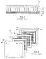
- While the filter press arrangementis conceptually simple and easily executed, it has some distinct drawbacks.
- the largest of these drawbacksis the amount that it adds to the weight and the bulk of the stack. Since a large compressive force is required, the stack must have heavy tensile members (tie rods) to apply this force, with large terminations, and heavy end plates to distribute this force evenly over the area of the stack. Both of these features add to the weight and the bulk of the fuel cell stack.
- FIG. 4shows an apparatus 50 that was used to ascertain the contribution of each of the materials in a standard fuel cell stack to the overall heat transfer.
- This deviceused an electrical heater 52 to heat a copper plate 54 to simulate the heat generated by a membrane and electrode assembly (M&E) during normal operation.
- a typical gas diffusion structure 56type ELAT from E-Tek, Inc., Natick, Mass., was placed against the copper plate. This was backed by a flow field element, with two different types illustrated here, an expanded Ti sheet 58 , at left, and a sheet of Ni foam 60 , like that shown in FIG. 5 , at right.
- the central componentwas a water cooled bipolar plate assembly 62 .
- thermocouples 64To determine the thermal resistivity of the components, a stable cooling water flow is established and power is supplied to the heating elements. The temperature of the two heating elements 52 was raised until the copper plate 54 was at the desired M&E operating temperature and the unit was left in this state until a steady state was achieved, based on a stable cooling water exit temperature and no change in any of the readings of the thermocouples 64 (shown as dots).
- the present inventionprovides an apparatus for use in electrochemical devices comprising a porous metal flow field having a first face and a porous metal gas diffusion layer metallurgically bonded to the first face of the expanded metal flow field.
- the apparatusmay further comprise a metal gas barrier having a first face metallurgically bonded to a second face of the porous metal flow field.
- the porous metal gas diffusionis treated with a wet proofing agent.
- the apparatusmay further comprise a second porous metal flow field having a first face metallurgically bonded to a second face of the metal gas barrier, such as a metal sheet or a fluid cooled plate, and a second porous metal gas diffusion layer having a face metallurgically bonded to a second face of the second porous metal flow field.
- the porous metal flow fieldis selected from metal foam, expanded metal sheet, sintered metal particles or sintered metal fibers and the porous metal gas diffusion layer is selected from sintered metal particles or sintered metal fibers.
- the metallurgical bondsare formed by a process selected from welding, brazing, soldering, sintering, fusion bonding, vacuum bonding, or combinations thereof.
- the inventionalso provides an apparatus for use in electrochemical devices comprising a porous metal flow field having a first face, and a gas diffusion layer in contact with the porous metal flow field, the gas diffusion layer comprising a gas diffusion matrix and a metal current collector disposed within the gas diffusion matrix, wherein the gas diffusion matrix comprises conductive carbon fiber, conductive carbon powder and a hydrophobic bonding material, such as polytetrafluoroethylene.
- the metal current collectoris a metal grid.
- FIGS. 1A and 1Bare schematic diagrams of a conventional stack of United Technologies Corporation's 4.5 MW demonstrator stack and a ribbed substrate stack, respectively.
- FIG. 2is a cross-sectional view of a conventional electrode assembly used in PEM fuel cells.
- FIG. 3is a schematic diagram of a standard filter press type fuel cell stack showing the arrangement of the bipolar cell plates and end plates.
- FIG. 4is a schematic diagram illustrating the locations of the thermocouples in a heat flow simulator for a PEM fuel cell stack.
- FIG. 5is an image of a piece of foamed metal illustrating its open foam structure.
- FIG. 6is a cross-sectional view of an electrode fabricated using gas diffusion electrodes with a metal grid replacing the carbon cloth.
- FIG. 7is a graph showing the polarization curves for M&E's produced using two different metal substrates for gas diffusion structures with ink type electrodes.
- FIG. 8is a graph comparing the polarization curves obtained with M&E's made with conventional carbon cloth substrates in the gas diffusers using NafionTM 105 and 112 membranes.
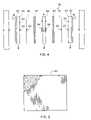
- FIGS. 9A and 9Bare pressure imprint films obtained at 82% scale for a traditional manifold-in-endplate 25 cm 2 single cell and a foam flow field based 32 cm 2 single cell, respectively.
- FIG. 10is a graph showing the polarization curve for a two-cell PEM fuel cell stack with an active area of 125 cm 2 operating with three-fold air stoichiometry and two-fold fuel stoichiometry.
- FIG. 11is a graph showing the flow resistance, plotted as pressure drop, for air flowing through a foamed metal flow field.
- FIG. 12is a magnified drawing of a sintered sphere electrolyzer substrate.
- FIG. 13is a cross-sectional view of a metal foam flow field with a sintered metal gas diffuser as its face.
- FIG. 14is a perspective view of the face of a unitized bipolar plate illustrating some of the key features.
- FIG. 15is a cross-sectional view of the unitized bipolar plate shown in FIG. 14 .
- the invention disclosed hereis an improved component or subassembly for use in electrochemical devices, such as fuel cells.
- the component or subassemblyprovides a metal structure having higher electrical conductivity than conventional bipolar plates or stack structures.
- the individual metal members of the subassemblyare metallurgically bonded by welding, sintering, brazing, or soldering techniques known in the art. Additional bonding techniques and components are disclosed in U.S. Pat. No. 6,602,631 which is incorporated herein by reference.
- Metals such as Ti and Nihave substantially higher electrical and thermal conductivities than graphite, the most conductive form of carbon. Typical gas diffusion structures are produced using conductive carbon black, not graphite, and so are even less conductive. Therefore, higher intrinsic conductivity is the first key advantage of a metal gas diffusion structure in accordance with the present invention.
- a second advantage of the present inventioncomes from the way the individual metal particles are formed into the gas diffusion structure.
- Conductive carbonrequires the use of a separate bond phase, typically PTFE from an aqueous suspension. All of the conductivity relies on particle to particle contacts between carbon particles, with the PTFE bond phase impeding conductivity further.
- the particlesare metallurgically bonded, actually sintered, into a single piece. In this manner, the full conductivity of the metal can be realized to provide superior performance.
- the PTFEserves a second function, besides bonding, in a conventional gas diffusion structure. That function is wet-proofing, to improve the rate of liquid water removal from the vicinity of the electrode.
- an all metal gas diffuserwould be hydrophilic. This hydrophilic quality is overcome by one embodiment of the invention by using a fluoropolymer wet proofing agent, such as FluoradTM FC-722 from 3M of St. Paul, Minn., to make metallic flow fields fully water rejecting or hydrophobic.
- FIG. 6is a cross sectional view of an M&E 70 fabricated using metal grids 72 in place of the conductive carbon cloth in a gas diffusion layer of a conventional PEM electrode.
- FIG. 7is a graph showing the results obtained with M&E's 70 produced as shown in FIG. 6 . Results are shown for electrodes fabricated with both expanded metal grids and foamed metal sheets replacing the carbon substrate in the gas diffusion structure. While these results are not impressive by conventional bipolar fuel cell standards, this data was obtained from a monopolar fuel cell operating at ambient pressures and near ambient temperatures with air supplied by diffusion, not a compressor. This last fact limits the achievable current density before mass transfer limitations suffocates the cell. At the time that this data was collected, the gas diffusion structures were under no compression. The best data obtained for a conventional carbon cloth based electrode support under the same conditions is illustrated in FIG. 8 . When the data in FIG. 7 is compared to FIG. 8 , the improvement is indeed significant. It is clear that gas diffusion structures having metal grids offer superior performances at low pressures than conventional carbon cloth containing structures.
- FIG. 9Ashows a pressure imprint film 80 of a fuel cell with 1/32′′ deep by 1/32′′ wide flow field/manifolds in two 5 ⁇ 8′′ thick titanium endplates that have been polished, lapped and gold plated. This film was sandwiched between two 25 cm 2 , 0.016′′ thick, gas diffusion electrode backings, type ELAT obtained from E-TEK, Inc. of Natick, Mass., which were gasketed with 0.020′′ thick unsintered PTFE sheeting. (The pressure imprint film is essentially positioned in place of the proton exchange membrane).
- a torque of 30 inch-poundswas applied to four 5/16′′–18 stainless steel bolts.
- the four circles 82located at each corner, represent the bolt locations and the center square 84 represents the true electrode/manifold area.
- Darker shading, such as at points 86indicates low pressure. There is a distinct manifold pattern expressed in this imprint.
- Light areas or linesindicate where the solid ridges of the manifold compressed the gas diffuser.
- Darker areas or lines 88indicate the location of the furrows of the manifold where contact is deficient.
- the lower portion of the electrode areaalso has a darker hue that represents poor contact to that surface probably due to deformation during machining.
- the solid area 89 around the active electrode areais where sealing takes place.
- the space between the bolting holes and the corners of the electrode surfaceis critical to obtaining a good seal. This area has an even imprint, though grainy, which suggest that this assembly will not leak.
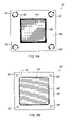
- FIG. 9Bis another pressure imprint film 90 similar to that of FIG. 9A , but for a foam-flow field cell of the present invention.
- This 32 cm 2 active area cellhad solid aluminum manifolding cell frames (0.048′′ thick) surrounding a gold plated 200-5 series. nickel foam (Astro Met, Inc.) 0.042′′ thick with a nominal density of 5% that of solid metal and a nominal pore spacing of 80 pores per linear inch.
- This foam-flow field waferis similarly up against an ELAT gas diffuser, as above (0.016′′ thick). Both the flow field and the gas diffuser were compressed to 0.048′′ to match the thickness of the surrounding cell frame. Again, the same load was applied, but to a pair of titanium end plates that were not polished and lapped.
- the holes in the diagramrepresent entry and exit ports for the two reactant gases and coolant liquid. Bolting was accomplished outside the border of the cell frame.
- Critical to the sealing of the assemblyis that complete compression is observed around these holes and on the exterior borders of the cell frame.
- the film in this exampleshows complete compression for these areas, as opposed to the grainy shading for the machined configuration of FIG. 9A .
- the interior electrode surfaceshows a more uniform impression throughout the active area.
- the dark impressions on the inside portion of the cell framerepresent the manifolding plenum of the assembly, which does not function as a sealing surface.
- FIG. 10shows a polarization curve for a two cell stack of 125 cm 2 active area per cell with nickel foam flow fields.
- the gold plated nickel foam usedwas initially 0.080′′ thick and was compressed to 0.050.′′
- the nickel foamhas a nominal density of 5% that of solid metal and a nominal pore spacing of 80 pores per linear inch.
- the foamwas wet-proofed with Flourad® 722 (3M Co., St Paul, Minn.), a fluoropolymer coating, and was assembled between gold plated titanium foil bipolar spacers and an uncatalyzed type ELAT gas diffusion/current distribution layer, which was placed against a Gore Select membrane with ink electrodes for both cathodes and anodes.
- Flourad® 7223M Co., St Paul, Minn.
- FIG. 11shows the log-log plot of pressure drop vs. flow rate. This function is a straight line at all operating pressures, indicating a power function correlation, normal for turbulent flow.
- a PEM fuel cell of this sizewould require a flow of 3.3 L(STP)/min to supply sufficient air to maintain two-fold stoichiometry at a current density of 1 A/cm 2 .
- the flow resistance seen hereis clearly adequately low for PEM fuel cell stack applications.
- FIG. 12is a schematic cross-sectional view of a typical sintered sphere component 92 .
- Micro and macro particle sintered porous metalscan be used to form the electrode substrates and current collectors of the present invention.
- Porous titanium sheets(0.045′′ thick) made from sintered titanium spheres that have been screened to a uniform diameter, with metal oxides thermally or electrically deposited thereon, have been used as anodes positioned against the PEM electrolyte for the electrochemical generation of high concentration ozone, such as for environmental remediation and disinfection applications.
- a Light undercoating of noble metals on these substratesinsures a long service life (over 98 days, or over 2,200 hours), and stable operation (no increments required in the stack potential to maintain constant current at constant temperatures over an extended time) even in a very corrosive environment.
- Gold plated stock of these materialsalso function well as current collectors against electrocatalyst ink decals on the PEM for the electrochemical generation of hydrogen from water or methanol.
- FIG. 13shows a structure 100 implementing the novel approach of having expanded metal or porous foam flow fields 102 , like that illustrated in FIG. 5 , as supporting substrates during sintering to enable the manufacture of a thin porous gas diffusion layer 104 bonded by sintering directly onto the flow field 102 for optimal electrical and thermal conductivity.
- the subassemblycomprising a porous metal flow field 102 having a porous metal gas diffusion layer 104 sintered thereto is illustrated in FIG. 13 having a membrane 106 with ink type electrodes 108 , 109 formed onto the membrane 106 . It should be recognized that the electrodes could also be formed onto the gas diffusion layer 104 within the scope of the present invention.
- Sintered metal feltsobtained from Newmet Krebs ⁇ ge of Terryville, Conn., provide another approach. These sintered metal felts are commercially available in nickel, stainless steel, and other metals and can be fabricated on a support. While the current commercially available materials are generally too thick for this application, thinner materials can be made if needed.
- the use of a porous metal flow fieldfacilitates the sintering, or furnace welding, of the flow field to a metal gas barrier.
- Thismakes it possible to produce a completely unitized bipolar plate or subassembly, with continuous metal from the anode of one cell to the cathode of the next cell in the stack, for the maximal electrical conductivity.
- the incorporation of fluid cooled bipolar plates as the metal gas barrierwill involve more components, but may be incorporated into the subassemblies of the present invention while still having far fewer interfaces than a conventional bipolar cell arrangement, thereby providing lower contact resistances than other designs.
- FIG. 15shows a unitized bipolar plate or subassembly 110 of the present invention having a three layer system for each half cell: a thin metal foil separator or gas barrier 112 , a porous metal foam flow field 102 , and a microporous current/heat distribution layer 104 with a gas diffusion matrix (an additional flow field 102 and gas distribution layer 104 are preferably formed on the back of separator 112 ).
- a porous metal flow field 102not a grooved sheet, makes this approach fundamentally different from the solid pieces with formed or patterned sheets disclosed by Neutzler in U.S. Pat. No. 5,776,624.
- the present inventionprovides for welding all of the components into a single mass of metal using a high productivity method (gang sintering in a furnace) and the inclusion of the gas diffusion layer as part of this monolithic structure.
- Thisleads to better electronic or electrical conductivity from the face of one electrode to the face of another electrode, fewer opportunities for corrosion, and fewer opportunities for failure due to components shifting their relative positions, since several pieces are replaced by a single piece.
- the gas diffusion layer included as part of the same structurethe electrical resistance is lowered still further, and mass transfer to the electrode is enhanced.
- Substituting a porous metal support structure for the carbon fiber structureprovides a more rugged structure, with improved electronic conductivity, a reduced need for compression of the electrochemical cell components, and permit operation of the electrochemical cell at lower pressures.
- This exampledemonstrates a unitized flow field-electrode support structure.
- a gas diffusion structurewas fabricated directly on a metallic flow field element, without the use of conductive carbon cloth or paper.
- the gas diffusion layerwas a mixture of three components, high surface area, high conductivity, carbon black Vulcan® XC-72R, CABOT Technology Division, Pampa, Tex. 79066), conductive carbon fiber (Thomel® DKD-X, from AMOCO, Alpharetta, Ga. 30202) and PTFB (T-30 suspension, DuPont). Water was added to the mixture as needed for mixing, and a nonionic surfactant (Triton X100, Fisher Scientific, Fair Lawn, N.J. 07410) was used to maintain dispersion.
- Triton X100Triton X100, Fisher Scientific, Fair Lawn, N.J. 07410
- the componentswere combined and mixed to fully disperse the solids and produce a uniform paste.
- This pastewas applied to the cleaned metallic conductor (expanded metal or foamed metal flow field) to form a gas diffusion matrix.
- the gas diffusion/flow field assemblycomprised of the gas diffusion matrix and the metallic conductor flow field was dried at room temperature under vacuum, then further dried at 60° C. in a vacuum oven. The assembly was then treated in an argon atmosphere at 320° C. for 2 hours to sinter the PTFE and decompose the surfactant. The loading of the carbon powder, carbon fiber, and PTFE totaled about 0.02 g/cm 2 . These gas diffusion layers were used to produce the cells demonstrated in FIG. 7 which performed well.
- the paste described in Example 1may be applied to a metal current collector, such as a metal grid, and dried under the same conditions.
- the resulting gas diffusion layermay then be used in contact with a porous metal flow field, such as an expanded metal or foamed metal.
Landscapes
- Chemical & Material Sciences (AREA)
- General Chemical & Material Sciences (AREA)
- Electrochemistry (AREA)
- Chemical Kinetics & Catalysis (AREA)
- Engineering & Computer Science (AREA)
- Sustainable Energy (AREA)
- Life Sciences & Earth Sciences (AREA)
- Sustainable Development (AREA)
- Manufacturing & Machinery (AREA)
- Composite Materials (AREA)
- Materials Engineering (AREA)
- Fuel Cell (AREA)
- Inert Electrodes (AREA)
- Lighters Containing Fuel (AREA)
- Hybrid Cells (AREA)
- Battery Electrode And Active Subsutance (AREA)
Abstract
Description
| TABLE I |
| Properties of Materials Useful for Bipolar Plates |
| Specific Resistivity | ||||
| Element | (μΩ-cm) | Density (g/mL) | Mass (g) | R (μΩ) |
| Cu | 1.673 | 8.89 | 250 | 0.009 |
| Al | 2.655 | 2.70 | 75.9 | 0.014 |
| Mg | 4.450 | 1.74 | 48.9 | 0.024 |
| Ti | 42.0 | 4.50 | 127 | 0.23 |
| Ca | 1375 | 2.25 | 63.3 | 7.4 |
| aGraphite | ||||
Claims (20)
Priority Applications (1)
| Application Number | Priority Date | Filing Date | Title |
|---|---|---|---|
| US10/274,494US6991869B2 (en) | 1999-05-08 | 2002-10-17 | Unitized barrier and flow control device for electrochemical reactors |
Applications Claiming Priority (3)
| Application Number | Priority Date | Filing Date | Title |
|---|---|---|---|
| US09/307,410US6232010B1 (en) | 1999-05-08 | 1999-05-08 | Unitized barrier and flow control device for electrochemical reactors |
| US09/680,377US6562507B1 (en) | 1998-03-03 | 2000-10-05 | Unitized barrier and flow control device for electrochemical reactors |
| US10/274,494US6991869B2 (en) | 1999-05-08 | 2002-10-17 | Unitized barrier and flow control device for electrochemical reactors |
Related Parent Applications (1)
| Application Number | Title | Priority Date | Filing Date |
|---|---|---|---|
| US09/680,377DivisionUS6562507B1 (en) | 1998-03-03 | 2000-10-05 | Unitized barrier and flow control device for electrochemical reactors |
Publications (2)
| Publication Number | Publication Date |
|---|---|
| US20030124411A1 US20030124411A1 (en) | 2003-07-03 |
| US6991869B2true US6991869B2 (en) | 2006-01-31 |
Family
ID=23189643
Family Applications (3)
| Application Number | Title | Priority Date | Filing Date |
|---|---|---|---|
| US09/307,410Expired - LifetimeUS6232010B1 (en) | 1998-03-03 | 1999-05-08 | Unitized barrier and flow control device for electrochemical reactors |
| US09/680,377Expired - Fee RelatedUS6562507B1 (en) | 1998-03-03 | 2000-10-05 | Unitized barrier and flow control device for electrochemical reactors |
| US10/274,494Expired - LifetimeUS6991869B2 (en) | 1999-05-08 | 2002-10-17 | Unitized barrier and flow control device for electrochemical reactors |
Family Applications Before (2)
| Application Number | Title | Priority Date | Filing Date |
|---|---|---|---|
| US09/307,410Expired - LifetimeUS6232010B1 (en) | 1998-03-03 | 1999-05-08 | Unitized barrier and flow control device for electrochemical reactors |
| US09/680,377Expired - Fee RelatedUS6562507B1 (en) | 1998-03-03 | 2000-10-05 | Unitized barrier and flow control device for electrochemical reactors |
Country Status (8)
| Country | Link |
|---|---|
| US (3) | US6232010B1 (en) |
| EP (2) | EP1214749B1 (en) |
| AT (1) | ATE292326T1 (en) |
| AU (1) | AU4816500A (en) |
| DE (1) | DE60019139T2 (en) |
| ES (1) | ES2237427T3 (en) |
| TW (1) | TW475293B (en) |
| WO (1) | WO2000069003A2 (en) |
Cited By (6)
| Publication number | Priority date | Publication date | Assignee | Title |
|---|---|---|---|---|
| US20030118888A1 (en)* | 2001-12-05 | 2003-06-26 | Gencell Corporation | Polymer coated metallic bipolar separator plate and method of assembly |
| WO2008102578A1 (en)* | 2007-02-19 | 2008-08-28 | Toyota Jidosha Kabushiki Kaisha | Fuel cell, laminate for fuel cell, and method of manufacturing the same |
| US20100178580A1 (en)* | 2009-01-13 | 2010-07-15 | Gm Global Technology Operations, Inc. | Bipolar plate for a fuel cell stack |
| US20110014538A1 (en)* | 2009-07-16 | 2011-01-20 | Ford Motor Company | Fuel cell |
| US20110014537A1 (en)* | 2009-07-16 | 2011-01-20 | Ford Motor Company | Fuel cell |
| WO2023208279A2 (en) | 2022-04-27 | 2023-11-02 | Schaeffler Technologies AG & Co. KG | Electrochemical cell and method for producing a component of an electrochemical cell |
Families Citing this family (76)
| Publication number | Priority date | Publication date | Assignee | Title |
|---|---|---|---|---|
| US6232010B1 (en)* | 1999-05-08 | 2001-05-15 | Lynn Tech Power Systems, Ltd. | Unitized barrier and flow control device for electrochemical reactors |
| US6638659B1 (en)* | 1999-04-30 | 2003-10-28 | University Of Connecticut | Membrane electrode assemblies using ionic composite membranes |
| WO2001059862A2 (en)* | 2000-02-11 | 2001-08-16 | The Texas A & M University System | Electroconductive fuel cell component with directly bonded layers and method for making same |
| US6770394B2 (en)* | 2000-02-11 | 2004-08-03 | The Texas A&M University System | Fuel cell with monolithic flow field-bipolar plate assembly and method for making and cooling a fuel cell stack |
| US6828054B2 (en) | 2000-02-11 | 2004-12-07 | The Texas A&M University System | Electronically conducting fuel cell component with directly bonded layers and method for making the same |
| JP3594533B2 (en)* | 2000-05-30 | 2004-12-02 | 三洋電機株式会社 | Fuel cell |
| SE522666C2 (en)* | 2000-07-07 | 2004-02-24 | Volvo Ab | Gas distribution element for fuel cells, fuel cell and method for producing a gas distribution element |
| US6663994B1 (en) | 2000-10-23 | 2003-12-16 | General Motors Corporation | Fuel cell with convoluted MEA |
| US6566004B1 (en) | 2000-08-31 | 2003-05-20 | General Motors Corporation | Fuel cell with variable porosity gas distribution layers |
| US7592089B2 (en)* | 2000-08-31 | 2009-09-22 | Gm Global Technology Operations, Inc. | Fuel cell with variable porosity gas distribution layers |
| US6531238B1 (en) | 2000-09-26 | 2003-03-11 | Reliant Energy Power Systems, Inc. | Mass transport for ternary reaction optimization in a proton exchange membrane fuel cell assembly and stack assembly |
| US6589679B1 (en) | 2000-11-22 | 2003-07-08 | Mti Microfuel Cells Inc. | Apparatus and methods for sensor-less optimization of methanol concentration in a direct methanol fuel cell system |
| US6824899B2 (en)* | 2000-11-22 | 2004-11-30 | Mti Microfuel Cells, Inc. | Apparatus and methods for sensor-less optimization of methanol concentration in a direct methanol fuel cell system |
| AU2002225675A1 (en)* | 2000-11-22 | 2002-06-03 | Powercell Corporation | Bipolar plate and method of manufacturing same |
| FR2820244B1 (en)* | 2001-01-26 | 2003-12-12 | Technicatome | LIGHT BIPOLAR PLATE FOR FUEL CELL AND MANUFACTURING METHOD THEREOF |
| WO2002064293A1 (en)* | 2001-02-16 | 2002-08-22 | Sumitomo Titanium Corporation | Titanium powder sintered compact |
| SE516741C2 (en)* | 2001-02-27 | 2002-02-26 | Cellkraft Ab | Bipolar plate for fuel cell or electrochemical reactor and use of the plate in a fuel cell stack or electrochemical reactor |
| WO2002075893A2 (en) | 2001-03-16 | 2002-09-26 | Creare Inc. | Lightweight direct methanol fuel cell and supporting systems |
| US6632553B2 (en)* | 2001-03-27 | 2003-10-14 | Mti Microfuel Cells, Inc. | Methods and apparatuses for managing effluent products in a fuel cell system |
| JP2002343379A (en)* | 2001-05-21 | 2002-11-29 | Aisin Seiki Co Ltd | Fuel cell, fuel cell electrode, and method of treating fuel cell electrode |
| US20020192537A1 (en)* | 2001-06-15 | 2002-12-19 | Xiaoming Ren | Metallic layer component for use in a direct oxidation fuel cell |
| US6913844B2 (en)* | 2001-06-29 | 2005-07-05 | Porvair Corporation | Method for humidifying reactant gases for use in a fuel cell |
| US6811918B2 (en)* | 2001-11-20 | 2004-11-02 | General Motors Corporation | Low contact resistance PEM fuel cell |
| US20030134178A1 (en)* | 2001-12-21 | 2003-07-17 | 3M Innovative Properties Company | Precompressed gas diffusion layers for electrochemical cells |
| EP1327492A1 (en)* | 2002-01-15 | 2003-07-16 | N.V. Bekaert S.A. | Porous metal stack for fuel cells or electrolysers |
| EP1328030A1 (en)* | 2002-01-15 | 2003-07-16 | N.V. Bekaert S.A. | Metal stack for fuel cells or electrolysers |
| US6981877B2 (en)* | 2002-02-19 | 2006-01-03 | Mti Microfuel Cells Inc. | Simplified direct oxidation fuel cell system |
| DE20204606U1 (en) | 2002-03-22 | 2002-07-04 | Lange, Dieter, 17489 Greifswald | Fuel cell package and end plate for it |
| US6858341B2 (en)* | 2002-05-21 | 2005-02-22 | Idatech, Llc | Bipolar plate assembly, fuel cell stacks and fuel cell systems incorporating the same |
| WO2003103073A2 (en)* | 2002-05-31 | 2003-12-11 | Evionyx, Inc. | Method of manufacturing metal air cell system |
| JP3760895B2 (en)* | 2002-07-03 | 2006-03-29 | 日本電気株式会社 | LIQUID FUEL SUPPLY FUEL CELL, FUEL CELL ELECTRODE, AND METHOD FOR PRODUCING THEM |
| CA2435988A1 (en)* | 2002-07-25 | 2004-01-25 | Global Thermoelectric Inc. | Metal foam interconnect |
| US6838202B2 (en)* | 2002-08-19 | 2005-01-04 | General Motors Corporation | Fuel cell bipolar plate having a conductive foam as a coolant layer |
| US20040062980A1 (en)* | 2002-09-30 | 2004-04-01 | Xiaoming Ren | Fluid management component for use in a fuel cell |
| US7297430B2 (en)* | 2002-10-01 | 2007-11-20 | Mti Microfuel Cells, Inc. | Anode diffusion layer for a direct oxidation fuel cell |
| US7001687B1 (en) | 2002-10-04 | 2006-02-21 | The Texas A&M University System | Unitized MEA assemblies and methods for making same |
| US7005209B1 (en) | 2002-10-04 | 2006-02-28 | The Texas A&M University System | Fuel cell stack assembly |
| EP1568095A2 (en)* | 2002-12-04 | 2005-08-31 | Lynntech Power Systems Limited | Adhesively bonded electrochemical cell stacks |
| JP2004273359A (en)* | 2003-03-11 | 2004-09-30 | Sumitomo Electric Ind Ltd | Porous member, method for producing the same, and electrochemical device using the same |
| US7407721B2 (en)* | 2003-04-15 | 2008-08-05 | Mti Microfuel Cells, Inc. | Direct oxidation fuel cell operating with direct feed of concentrated fuel under passive water management |
| US20050170224A1 (en)* | 2003-04-15 | 2005-08-04 | Xiaoming Ren | Controlled direct liquid injection vapor feed for a DMFC |
| US7282293B2 (en)* | 2003-04-15 | 2007-10-16 | Mti Microfuel Cells Inc. | Passive water management techniques in direct methanol fuel cells |
| DE10323880A1 (en)* | 2003-05-26 | 2004-12-23 | Siemens Ag | Bipolar plate and fuel cell with such a bipolar plate |
| US20040247927A1 (en)* | 2003-06-06 | 2004-12-09 | Kurz Douglas L. | Method of producing seamless, multi-layer, bonded, metallic, laminate strips or coils of arbitrarily long length |
| US7093623B2 (en)* | 2003-06-27 | 2006-08-22 | The Gillette Company | Methods of providing refueling for fuel cell-powered devices |
| US20050017055A1 (en)* | 2003-07-24 | 2005-01-27 | Kurz Douglas L. | Electrochemical fuel cell component materials and methods of bonding electrochemical fuel cell components |
| US7923137B2 (en) | 2003-10-09 | 2011-04-12 | Eveready Battery Company, Inc. | Nonaqueous cell with improved thermoplastic sealing member |
| DE10347793A1 (en)* | 2003-10-14 | 2005-05-19 | Robert Bosch Gmbh | Fuel cell system for generating electricity from chemical reactions has control unit designed to fill and empty fuel cell unit in at least one operating mode |
| US20050142398A1 (en)* | 2003-12-24 | 2005-06-30 | General Electric Company | Prevention of chromia-induced cathode poisoning in solid oxide fuel cells (SOFC) |
| USD586746S1 (en)* | 2004-07-01 | 2009-02-17 | Panasonic Corporation | Separator for fuel cell |
| US7029587B2 (en)* | 2004-04-02 | 2006-04-18 | Lynntech, Inc. | Water purification |
| US7687175B2 (en)* | 2004-05-03 | 2010-03-30 | Gm Global Technology Operations, Inc. | Hybrid bipolar plate assembly and devices incorporating same |
| DE102004023712B4 (en)* | 2004-05-11 | 2007-02-01 | Schunk Kohlenstofftechnik Gmbh | Bipolar plate and method for producing a bipolar plate of a fuel cell |
| EP1780822B1 (en)* | 2005-11-01 | 2012-01-18 | Tomoegawa Co., Ltd. | Gas diffusion electrode, membrane-electrode assembly, polymer electrolyte fuel cell, and methods for producing |
| US7785748B2 (en)* | 2006-04-03 | 2010-08-31 | University Of Delaware | Nano-based gas diffusion media |
| DE102006040030B4 (en)* | 2006-08-23 | 2009-09-03 | Fraunhofer-Gesellschaft zur Förderung der angewandten Forschung e.V. | Stacking unit for a stack of electrochemical cells, stacking arrangement and method for producing a stacking unit |
| JP4678359B2 (en) | 2006-10-25 | 2011-04-27 | トヨタ車体株式会社 | Fuel cell |
| JP5046612B2 (en)* | 2006-10-27 | 2012-10-10 | 本田技研工業株式会社 | Fuel cell |
| US8455155B2 (en)* | 2006-11-22 | 2013-06-04 | GM Global Technology Operations LLC | Inexpensive approach for coating bipolar plates for PEM fuel cells |
| DE102007016905A1 (en)* | 2007-04-02 | 2008-10-09 | Staxera Gmbh | Interconnector arrangement and method for producing a contact arrangement for a fuel cell stack |
| JP5067577B2 (en) | 2008-12-01 | 2012-11-07 | トヨタ自動車株式会社 | Fuel cell |
| EP2211406B1 (en)* | 2009-01-15 | 2012-05-30 | STMicroelectronics (Tours) SAS | Fuel cell electrode |
| US8506787B2 (en)* | 2009-07-31 | 2013-08-13 | Infinity Fuel Cell And Hydrogen, Inc. | Electrochemical cell |
| WO2011150458A1 (en)* | 2010-06-01 | 2011-12-08 | The University Of Queensland | A fuel cell stack |
| GB2505693A (en)* | 2012-09-07 | 2014-03-12 | Univ Dublin City | A proton exchange membrane fuel cell with open pore cellular foam |
| JP6439263B2 (en)* | 2014-03-20 | 2018-12-19 | 東レ株式会社 | Gas diffusion electrode manufacturing equipment |
| KR101816342B1 (en)* | 2014-12-12 | 2018-01-08 | 현대자동차주식회사 | Fuel cell stack |
| DE102015225717A1 (en)* | 2015-12-17 | 2017-06-22 | Robert Bosch Gmbh | Use of conductive and highly porous nonwovens as a bipolar plate in PEM fuel cells |
| DE102016213537A1 (en)* | 2016-07-25 | 2018-01-25 | Robert Bosch Gmbh | Method for producing a current collector for a fuel cell and fuel cell |
| GB2554387B (en)* | 2016-09-23 | 2019-04-17 | Univ Cape Town | A fuel cell component |
| JP2023512395A (en)* | 2020-02-26 | 2023-03-27 | トレッドストーン テクノロジーズ, アイエヌシー. | Component with improved surface contact resistance and reaction activity, and manufacturing method thereof |
| WO2022216387A2 (en)* | 2021-03-12 | 2022-10-13 | Precision Combustion Inc. | Backbone-structured metal-supported electrochemical cell |
| US12237515B2 (en) | 2021-10-22 | 2025-02-25 | Textron Innovations Inc. | Fuel cell metallic gas diffusion layer |
| CN114025142B (en)* | 2021-10-28 | 2023-06-13 | 四川启睿克科技有限公司 | Liquid cooling heat dissipation cold head, liquid cooling heat dissipation system and laser television |
| EP4292731A1 (en)* | 2022-06-17 | 2023-12-20 | Element 22 GmbH | Method for producing layered sheet structures from titanium or titanium alloys for use in electrodes of pem-type electrolyzers and/or fuel cells |
| EP4343898A1 (en)* | 2022-09-21 | 2024-03-27 | iGas energy GmbH | Combination of porous transport layer and bipolar plate for electrochemical cells |
Citations (35)
| Publication number | Priority date | Publication date | Assignee | Title |
|---|---|---|---|---|
| US3677721A (en) | 1970-12-07 | 1972-07-18 | Union Carbide Corp | Porous metal bodies of uniform porosity |
| US4175165A (en) | 1977-07-20 | 1979-11-20 | Engelhard Minerals & Chemicals Corporation | Fuel cell system utilizing ion exchange membranes and bipolar plates |
| US4297421A (en) | 1977-11-10 | 1981-10-27 | The International Nickel Co., Inc. | Battery and electrolytic cell electrodes |
| FR2506080A1 (en) | 1981-05-13 | 1982-11-19 | Inst Francais Du Petrole | Current collecting electrode support for electrochemical generators - esp. fuel cells, where metal foam is electrically and mechanically bonded to porous sintered metal layer |
| EP0115257A1 (en) | 1982-12-31 | 1984-08-08 | Mario Bertocci | Caburating displacement engine with pistons arranged one within another and slide-valves |
| US4533455A (en) | 1980-10-14 | 1985-08-06 | Oronzio De Nora Impianti Elettrochimici S.P.A. | Bipolar separator plate for electrochemical cells |
| EP0154772A1 (en) | 1984-01-26 | 1985-09-18 | BBC Brown Boveri AG | Bipolar plate for an apparatus made of a stack of electrochemical cells with solid electrolyte, and its manufacturing process |
| JPS61260550A (en) | 1985-05-15 | 1986-11-18 | Kobe Steel Ltd | Composite constituent element for fuel cell |
| US4900643A (en) | 1988-04-08 | 1990-02-13 | Globe-Union Inc. | Lead acid bipolar battery plate and method of making the same |
| US4973358A (en) | 1989-09-06 | 1990-11-27 | Alcan International Limited | Method of producing lightweight foamed metal |
| US5112703A (en) | 1990-07-03 | 1992-05-12 | Beta Power, Inc. | Electrochemical battery cell having a monolithic bipolar flat plate beta" al |
| US5200281A (en) | 1991-11-18 | 1993-04-06 | Westinghouse Electric Corp. | Sintered bipolar battery plates |
| US5264305A (en) | 1991-05-03 | 1993-11-23 | Energy Research Corporation | Zinc secondary battery having bipolar plate construction with horizontally disposed battery components |
| US5348817A (en) | 1993-06-02 | 1994-09-20 | Gnb Battery Technologies Inc. | Bipolar lead-acid battery |
| EP0629015A1 (en) | 1993-04-30 | 1994-12-14 | De Nora Permelec S.P.A. | Electrochemical cell provided with ion exchange membranes and bipolar plates |
| JPH07220734A (en)* | 1994-01-31 | 1995-08-18 | Mitsubishi Heavy Ind Ltd | Manufacture of gas diffusion electrode |
| US5496655A (en) | 1994-10-12 | 1996-03-05 | Lockheed Idaho Technologies Company | Catalytic bipolar interconnection plate for use in a fuel cell |
| US5584976A (en)* | 1995-04-28 | 1996-12-17 | Permelec Electrode Ltd. | Gas diffusion electrode |
| US5589662A (en) | 1992-09-21 | 1996-12-31 | Honda Giken Kogyo Kabushiki Kaisha | Pyrotechnic mixture and gas generator for an airbag |
| US5641586A (en) | 1995-12-06 | 1997-06-24 | The Regents Of The University Of California Office Of Technology Transfer | Fuel cell with interdigitated porous flow-field |
| EP0784352A1 (en) | 1995-07-05 | 1997-07-16 | Nisshinbo Industries, Inc. | Separator for fuel cells of solid polyelectrolyte type and processes of the production thereof |
| EP0817297A2 (en) | 1996-06-26 | 1998-01-07 | De Nora S.P.A. | Membrane electrochemical cell provided with gas diffusion electrodes in contact with porous, flat, metal current conductors having highly distributed contact area |
| JPH10172590A (en) | 1996-12-12 | 1998-06-26 | Fuji Electric Corp Res & Dev Ltd | Solid oxide fuel cell |
| US5776624A (en) | 1996-12-23 | 1998-07-07 | General Motors Corporation | Brazed bipolar plates for PEM fuel cells |
| WO1998033221A2 (en)* | 1997-01-24 | 1998-07-30 | Lynntech, Inc. | Bipolar plates for electrochemical cell stacks |
| US5800946A (en) | 1996-12-06 | 1998-09-01 | Grosvenor; Victor L. | Bipolar lead-acid battery plates |
| WO1999013522A1 (en) | 1997-09-05 | 1999-03-18 | Ceramic Fuel Cells Limited | Electrical conductivity in a fuel cell assembly |
| WO1999019927A1 (en)* | 1997-10-14 | 1999-04-22 | Nisshin Steel Co., Ltd. | Separator for low temperature type fuel cell and method of production thereof |
| DE19815796A1 (en) | 1998-04-08 | 1999-10-14 | Forschungszentrum Juelich Gmbh | Bipolar plate with porous wall |
| US5981098A (en) | 1997-08-28 | 1999-11-09 | Plug Power, L.L.C. | Fluid flow plate for decreased density of fuel cell assembly |
| US6020083A (en) | 1998-10-30 | 2000-02-01 | International Fuel Cells Llc | Membrane electrode assembly for PEM fuel cell |
| US6071636A (en) | 1997-06-10 | 2000-06-06 | Automobiles Peugeot | Fuel cell of the type with plate-shaped reagents distributors |
| US20010000485A1 (en)* | 1998-12-17 | 2001-04-26 | Qicong Ying | Protective coating for separators for electrochemical cells |
| US6232010B1 (en) | 1999-05-08 | 2001-05-15 | Lynn Tech Power Systems, Ltd. | Unitized barrier and flow control device for electrochemical reactors |
| US6410180B1 (en)* | 1996-06-06 | 2002-06-25 | Lynntech, Inc. | Fuel cell system for low pressure operation |
Family Cites Families (1)
| Publication number | Priority date | Publication date | Assignee | Title |
|---|---|---|---|---|
| US4733425A (en) | 1986-06-16 | 1988-03-29 | Sanderson-Macleod, Inc. | Mascara brush |
- 1999
- 1999-05-08USUS09/307,410patent/US6232010B1/ennot_activeExpired - Lifetime
- 2000
- 2000-05-03EPEP00930319Apatent/EP1214749B1/ennot_activeExpired - Lifetime
- 2000-05-03DEDE60019139Tpatent/DE60019139T2/ennot_activeExpired - Fee Related
- 2000-05-03AUAU48165/00Apatent/AU4816500A/ennot_activeAbandoned
- 2000-05-03ATAT00930319Tpatent/ATE292326T1/ennot_activeIP Right Cessation
- 2000-05-03WOPCT/US2000/012009patent/WO2000069003A2/enactiveIP Right Grant
- 2000-05-03EPEP04026826Apatent/EP1513206A3/ennot_activeWithdrawn
- 2000-05-03ESES00930319Tpatent/ES2237427T3/ennot_activeExpired - Lifetime
- 2000-09-08TWTW089118563Apatent/TW475293B/ennot_activeIP Right Cessation
- 2000-10-05USUS09/680,377patent/US6562507B1/ennot_activeExpired - Fee Related
- 2002
- 2002-10-17USUS10/274,494patent/US6991869B2/ennot_activeExpired - Lifetime
Patent Citations (42)
| Publication number | Priority date | Publication date | Assignee | Title |
|---|---|---|---|---|
| US3677721A (en) | 1970-12-07 | 1972-07-18 | Union Carbide Corp | Porous metal bodies of uniform porosity |
| US4175165A (en) | 1977-07-20 | 1979-11-20 | Engelhard Minerals & Chemicals Corporation | Fuel cell system utilizing ion exchange membranes and bipolar plates |
| US4297421A (en) | 1977-11-10 | 1981-10-27 | The International Nickel Co., Inc. | Battery and electrolytic cell electrodes |
| US4533455A (en) | 1980-10-14 | 1985-08-06 | Oronzio De Nora Impianti Elettrochimici S.P.A. | Bipolar separator plate for electrochemical cells |
| FR2506080A1 (en) | 1981-05-13 | 1982-11-19 | Inst Francais Du Petrole | Current collecting electrode support for electrochemical generators - esp. fuel cells, where metal foam is electrically and mechanically bonded to porous sintered metal layer |
| EP0115257A1 (en) | 1982-12-31 | 1984-08-08 | Mario Bertocci | Caburating displacement engine with pistons arranged one within another and slide-valves |
| EP0154772A1 (en) | 1984-01-26 | 1985-09-18 | BBC Brown Boveri AG | Bipolar plate for an apparatus made of a stack of electrochemical cells with solid electrolyte, and its manufacturing process |
| US4619753A (en) | 1984-01-26 | 1986-10-28 | Bbc Brown, Boveri & Company Limited | Bipolar plate for an apparatus with a stacked configuration, said apparatus comprised of a plurality of electrochemical cells with solid electrolyte; and method of manufacturing said plate |
| JPS61260550A (en) | 1985-05-15 | 1986-11-18 | Kobe Steel Ltd | Composite constituent element for fuel cell |
| US4900643A (en) | 1988-04-08 | 1990-02-13 | Globe-Union Inc. | Lead acid bipolar battery plate and method of making the same |
| US4973358A (en) | 1989-09-06 | 1990-11-27 | Alcan International Limited | Method of producing lightweight foamed metal |
| US5112703A (en) | 1990-07-03 | 1992-05-12 | Beta Power, Inc. | Electrochemical battery cell having a monolithic bipolar flat plate beta" al |
| US5264305A (en) | 1991-05-03 | 1993-11-23 | Energy Research Corporation | Zinc secondary battery having bipolar plate construction with horizontally disposed battery components |
| US5200281A (en) | 1991-11-18 | 1993-04-06 | Westinghouse Electric Corp. | Sintered bipolar battery plates |
| US5589662A (en) | 1992-09-21 | 1996-12-31 | Honda Giken Kogyo Kabushiki Kaisha | Pyrotechnic mixture and gas generator for an airbag |
| EP0629015A1 (en) | 1993-04-30 | 1994-12-14 | De Nora Permelec S.P.A. | Electrochemical cell provided with ion exchange membranes and bipolar plates |
| US5482792A (en) | 1993-04-30 | 1996-01-09 | De Nora Permelec S.P.A. | Electrochemical cell provided with ion exchange membranes and bipolar metal plates |
| US5578388A (en) | 1993-04-30 | 1996-11-26 | De Nora Permelec S.P.A. | Electrochemical cell provided with ion exchange membranes and bipolar metal plates |
| US5348817A (en) | 1993-06-02 | 1994-09-20 | Gnb Battery Technologies Inc. | Bipolar lead-acid battery |
| JPH07220734A (en)* | 1994-01-31 | 1995-08-18 | Mitsubishi Heavy Ind Ltd | Manufacture of gas diffusion electrode |
| US5496655A (en) | 1994-10-12 | 1996-03-05 | Lockheed Idaho Technologies Company | Catalytic bipolar interconnection plate for use in a fuel cell |
| US5584976A (en)* | 1995-04-28 | 1996-12-17 | Permelec Electrode Ltd. | Gas diffusion electrode |
| EP0784352A1 (en) | 1995-07-05 | 1997-07-16 | Nisshinbo Industries, Inc. | Separator for fuel cells of solid polyelectrolyte type and processes of the production thereof |
| US5641586A (en) | 1995-12-06 | 1997-06-24 | The Regents Of The University Of California Office Of Technology Transfer | Fuel cell with interdigitated porous flow-field |
| US6410180B1 (en)* | 1996-06-06 | 2002-06-25 | Lynntech, Inc. | Fuel cell system for low pressure operation |
| US6022634A (en) | 1996-06-26 | 2000-02-08 | De Nora S.P.A. | Membrane electrochemical cell provided with gas diffusion electrodes in contact with porour, flat, metal current conductors having highly distributed contact area |
| EP0817297A2 (en) | 1996-06-26 | 1998-01-07 | De Nora S.P.A. | Membrane electrochemical cell provided with gas diffusion electrodes in contact with porous, flat, metal current conductors having highly distributed contact area |
| EP0817297A3 (en) | 1996-06-26 | 1999-05-19 | De Nora S.P.A. | Membrane electrochemical cell provided with gas diffusion electrodes in contact with porous, flat, metal current conductors having highly distributed contact area |
| US5800946A (en) | 1996-12-06 | 1998-09-01 | Grosvenor; Victor L. | Bipolar lead-acid battery plates |
| JPH10172590A (en) | 1996-12-12 | 1998-06-26 | Fuji Electric Corp Res & Dev Ltd | Solid oxide fuel cell |
| US5776624A (en) | 1996-12-23 | 1998-07-07 | General Motors Corporation | Brazed bipolar plates for PEM fuel cells |
| WO1998033221A2 (en)* | 1997-01-24 | 1998-07-30 | Lynntech, Inc. | Bipolar plates for electrochemical cell stacks |
| US6071636A (en) | 1997-06-10 | 2000-06-06 | Automobiles Peugeot | Fuel cell of the type with plate-shaped reagents distributors |
| US5981098A (en) | 1997-08-28 | 1999-11-09 | Plug Power, L.L.C. | Fluid flow plate for decreased density of fuel cell assembly |
| WO1999013522A1 (en) | 1997-09-05 | 1999-03-18 | Ceramic Fuel Cells Limited | Electrical conductivity in a fuel cell assembly |
| WO1999019927A1 (en)* | 1997-10-14 | 1999-04-22 | Nisshin Steel Co., Ltd. | Separator for low temperature type fuel cell and method of production thereof |
| US6440598B1 (en)* | 1997-10-14 | 2002-08-27 | Nisshin Steel Co., Ltd. | Separator for low temperature type fuel cell and method of production thereof |
| US6562507B1 (en)* | 1998-03-03 | 2003-05-13 | Lynntech Power Systems, Ltd. | Unitized barrier and flow control device for electrochemical reactors |
| DE19815796A1 (en) | 1998-04-08 | 1999-10-14 | Forschungszentrum Juelich Gmbh | Bipolar plate with porous wall |
| US6020083A (en) | 1998-10-30 | 2000-02-01 | International Fuel Cells Llc | Membrane electrode assembly for PEM fuel cell |
| US20010000485A1 (en)* | 1998-12-17 | 2001-04-26 | Qicong Ying | Protective coating for separators for electrochemical cells |
| US6232010B1 (en) | 1999-05-08 | 2001-05-15 | Lynn Tech Power Systems, Ltd. | Unitized barrier and flow control device for electrochemical reactors |
Cited By (10)
| Publication number | Priority date | Publication date | Assignee | Title |
|---|---|---|---|---|
| US20030118888A1 (en)* | 2001-12-05 | 2003-06-26 | Gencell Corporation | Polymer coated metallic bipolar separator plate and method of assembly |
| WO2008102578A1 (en)* | 2007-02-19 | 2008-08-28 | Toyota Jidosha Kabushiki Kaisha | Fuel cell, laminate for fuel cell, and method of manufacturing the same |
| US20100178580A1 (en)* | 2009-01-13 | 2010-07-15 | Gm Global Technology Operations, Inc. | Bipolar plate for a fuel cell stack |
| US8889314B2 (en) | 2009-01-13 | 2014-11-18 | GM Global Technology Operations LLC | Bipolar plate for a fuel cell stack |
| DE102010004160B4 (en)* | 2009-01-13 | 2015-11-12 | GM Global Technology Operations LLC (n. d. Ges. d. Staates Delaware) | Bipolar plate assembly for a fuel cell stack and fuel cell stack |
| US20110014538A1 (en)* | 2009-07-16 | 2011-01-20 | Ford Motor Company | Fuel cell |
| US20110014537A1 (en)* | 2009-07-16 | 2011-01-20 | Ford Motor Company | Fuel cell |
| US8916313B2 (en) | 2009-07-16 | 2014-12-23 | Ford Motor Company | Fuel cell |
| WO2023208279A2 (en) | 2022-04-27 | 2023-11-02 | Schaeffler Technologies AG & Co. KG | Electrochemical cell and method for producing a component of an electrochemical cell |
| DE102022110126A1 (en) | 2022-04-27 | 2023-11-02 | Schaeffler Technologies AG & Co. KG | Electrochemical cell and method for producing a component of an electrochemical cell |
Also Published As
| Publication number | Publication date |
|---|---|
| US6562507B1 (en) | 2003-05-13 |
| AU4816500A (en) | 2000-11-21 |
| TW475293B (en) | 2002-02-01 |
| DE60019139T2 (en) | 2006-05-11 |
| EP1214749A2 (en) | 2002-06-19 |
| WO2000069003A2 (en) | 2000-11-16 |
| EP1214749B1 (en) | 2005-03-30 |
| DE60019139D1 (en) | 2005-05-04 |
| ES2237427T3 (en) | 2005-08-01 |
| EP1513206A2 (en) | 2005-03-09 |
| ATE292326T1 (en) | 2005-04-15 |
| US6232010B1 (en) | 2001-05-15 |
| US20030124411A1 (en) | 2003-07-03 |
| EP1513206A3 (en) | 2007-01-03 |
| WO2000069003A3 (en) | 2001-08-02 |
Similar Documents
| Publication | Publication Date | Title |
|---|---|---|
| US6991869B2 (en) | Unitized barrier and flow control device for electrochemical reactors | |
| US6828054B2 (en) | Electronically conducting fuel cell component with directly bonded layers and method for making the same | |
| US6770394B2 (en) | Fuel cell with monolithic flow field-bipolar plate assembly and method for making and cooling a fuel cell stack | |
| US7438985B2 (en) | Proton exchange membrane (PEM) electrochemical cell having an integral, electrically-conductive, resiliently compressible, porous pad | |
| Murphy et al. | Low-cost light weight high power density PEM fuel cell stack | |
| US5976726A (en) | Electrochemical cell with fluid distribution layer having integral sealing capability | |
| JP4916088B2 (en) | Porous carbon body for fuel cell having electrically conductive hydrophilic agent | |
| US7125625B2 (en) | Electrochemical cell and bipolar assembly for an electrochemical cell | |
| US20050048353A1 (en) | PEM fuel cell separator plate | |
| US20040018412A1 (en) | Electrochemical fuel cell comprised of a series of conductive compression gaskets and method of manufacture | |
| US20050017055A1 (en) | Electrochemical fuel cell component materials and methods of bonding electrochemical fuel cell components | |
| JP7486931B2 (en) | Method for manufacturing electrochemical reactor flow guides | |
| US8182659B2 (en) | Proton exchange membrane (PEM) electrochemical cell having an integral, electrically-conductive, resiliently compressible, porous pad | |
| US6649299B2 (en) | Gas diffusion electrode with nanosized pores and method for making same | |
| US7014947B2 (en) | Integral membrane support and frame structure | |
| CA2486216C (en) | Fuel cell having stack structure | |
| JP2010282975A (en) | FUEL CELL AND METHOD FOR MANUFACTURING FUEL CELL | |
| JP2006331670A (en) | Manufacturing method of fuel cell separator and fuel cell using this fuel cell separator | |
| WO2001059862A2 (en) | Electroconductive fuel cell component with directly bonded layers and method for making same | |
| WO2025085472A1 (en) | Porous metal layers, method of manufacture, and use thereof |
Legal Events
| Date | Code | Title | Description |
|---|---|---|---|
| AS | Assignment | Owner name:LYNNTECH POWER SYSTEMS, LTD., TEXAS Free format text:ASSIGNMENT OF ASSIGNORS INTEREST;ASSIGNOR:LYNNTECH, INC.;REEL/FRAME:013795/0607 Effective date:20000607 | |
| AS | Assignment | Owner name:LYNNTECH, INC., TEXAS Free format text:ASSIGNMENT OF ASSIGNORS INTEREST;ASSIGNORS:CISAR, ALAN J.;MURPHY, OLIVER J.;JENG, KING-TSAI;AND OTHERS;REEL/FRAME:013822/0469;SIGNING DATES FROM 19990615 TO 19990804 | |
| STCF | Information on status: patent grant | Free format text:PATENTED CASE | |
| AS | Assignment | Owner name:CITY BANK,TEXAS Free format text:SECURITY AGREEMENT;ASSIGNOR:LYNNTECH POWER SYSTEMS, LTD.;REEL/FRAME:019035/0853 Effective date:20070308 Owner name:CITY BANK, TEXAS Free format text:SECURITY AGREEMENT;ASSIGNOR:LYNNTECH POWER SYSTEMS, LTD.;REEL/FRAME:019035/0853 Effective date:20070308 | |
| FPAY | Fee payment | Year of fee payment:4 | |
| FEPP | Fee payment procedure | Free format text:PAYOR NUMBER ASSIGNED (ORIGINAL EVENT CODE: ASPN); ENTITY STATUS OF PATENT OWNER: SMALL ENTITY | |
| FPAY | Fee payment | Year of fee payment:8 | |
| FPAY | Fee payment | Year of fee payment:12 | |
| AS | Assignment | Owner name:LYNNTECH, INC., TEXAS Free format text:ASSIGNMENT OF ASSIGNORS INTEREST;ASSIGNOR:LYNNTECH POWER SYSTEMS, LTD.;REEL/FRAME:047281/0923 Effective date:20181012 |