US6991672B2 - Filter element comprising pleated metal fiber fleece - Google Patents
Filter element comprising pleated metal fiber fleeceDownload PDFInfo
- Publication number
- US6991672B2 US6991672B2US10/466,551US46655103AUS6991672B2US 6991672 B2US6991672 B2US 6991672B2US 46655103 AUS46655103 AUS 46655103AUS 6991672 B2US6991672 B2US 6991672B2
- Authority
- US
- United States
- Prior art keywords
- metal fiber
- fiber fleece
- filter element
- thermally
- filter
- Prior art date
- Legal status (The legal status is an assumption and is not a legal conclusion. Google has not performed a legal analysis and makes no representation as to the accuracy of the status listed.)
- Expired - Lifetime, expires
Links
Images


Classifications
- B—PERFORMING OPERATIONS; TRANSPORTING
- B01—PHYSICAL OR CHEMICAL PROCESSES OR APPARATUS IN GENERAL
- B01D—SEPARATION
- B01D39/00—Filtering material for liquid or gaseous fluids
- B01D39/14—Other self-supporting filtering material ; Other filtering material
- B01D39/20—Other self-supporting filtering material ; Other filtering material of inorganic material, e.g. asbestos paper, metallic filtering material of non-woven wires
- B01D39/2068—Other inorganic materials, e.g. ceramics
- B—PERFORMING OPERATIONS; TRANSPORTING
- B01—PHYSICAL OR CHEMICAL PROCESSES OR APPARATUS IN GENERAL
- B01D—SEPARATION
- B01D39/00—Filtering material for liquid or gaseous fluids
- B01D39/14—Other self-supporting filtering material ; Other filtering material
- B01D39/20—Other self-supporting filtering material ; Other filtering material of inorganic material, e.g. asbestos paper, metallic filtering material of non-woven wires
- B01D39/2027—Metallic material
- B01D39/2041—Metallic material the material being filamentary or fibrous
- B—PERFORMING OPERATIONS; TRANSPORTING
- B01—PHYSICAL OR CHEMICAL PROCESSES OR APPARATUS IN GENERAL
- B01D—SEPARATION
- B01D46/00—Filters or filtering processes specially modified for separating dispersed particles from gases or vapours
- B01D46/66—Regeneration of the filtering material or filter elements inside the filter
- B01D46/80—Chemical processes for the removal of the retained particles, e.g. by burning
- B01D46/84—Chemical processes for the removal of the retained particles, e.g. by burning by heating only
- F—MECHANICAL ENGINEERING; LIGHTING; HEATING; WEAPONS; BLASTING
- F01—MACHINES OR ENGINES IN GENERAL; ENGINE PLANTS IN GENERAL; STEAM ENGINES
- F01N—GAS-FLOW SILENCERS OR EXHAUST APPARATUS FOR MACHINES OR ENGINES IN GENERAL; GAS-FLOW SILENCERS OR EXHAUST APPARATUS FOR INTERNAL-COMBUSTION ENGINES
- F01N13/00—Exhaust or silencing apparatus characterised by constructional features
- F01N13/009—Exhaust or silencing apparatus characterised by constructional features having two or more separate purifying devices arranged in series
- F01N13/0097—Exhaust or silencing apparatus characterised by constructional features having two or more separate purifying devices arranged in series the purifying devices are arranged in a single housing
- F—MECHANICAL ENGINEERING; LIGHTING; HEATING; WEAPONS; BLASTING
- F01—MACHINES OR ENGINES IN GENERAL; ENGINE PLANTS IN GENERAL; STEAM ENGINES
- F01N—GAS-FLOW SILENCERS OR EXHAUST APPARATUS FOR MACHINES OR ENGINES IN GENERAL; GAS-FLOW SILENCERS OR EXHAUST APPARATUS FOR INTERNAL-COMBUSTION ENGINES
- F01N13/00—Exhaust or silencing apparatus characterised by constructional features
- F01N13/14—Exhaust or silencing apparatus characterised by constructional features having thermal insulation
- F—MECHANICAL ENGINEERING; LIGHTING; HEATING; WEAPONS; BLASTING
- F01—MACHINES OR ENGINES IN GENERAL; ENGINE PLANTS IN GENERAL; STEAM ENGINES
- F01N—GAS-FLOW SILENCERS OR EXHAUST APPARATUS FOR MACHINES OR ENGINES IN GENERAL; GAS-FLOW SILENCERS OR EXHAUST APPARATUS FOR INTERNAL-COMBUSTION ENGINES
- F01N3/00—Exhaust or silencing apparatus having means for purifying, rendering innocuous, or otherwise treating exhaust
- F01N3/02—Exhaust or silencing apparatus having means for purifying, rendering innocuous, or otherwise treating exhaust for cooling, or for removing solid constituents of, exhaust
- F01N3/021—Exhaust or silencing apparatus having means for purifying, rendering innocuous, or otherwise treating exhaust for cooling, or for removing solid constituents of, exhaust by means of filters
- F01N3/022—Exhaust or silencing apparatus having means for purifying, rendering innocuous, or otherwise treating exhaust for cooling, or for removing solid constituents of, exhaust by means of filters characterised by specially adapted filtering structure, e.g. honeycomb, mesh or fibrous
- F01N3/0226—Exhaust or silencing apparatus having means for purifying, rendering innocuous, or otherwise treating exhaust for cooling, or for removing solid constituents of, exhaust by means of filters characterised by specially adapted filtering structure, e.g. honeycomb, mesh or fibrous the structure being fibrous
- F—MECHANICAL ENGINEERING; LIGHTING; HEATING; WEAPONS; BLASTING
- F01—MACHINES OR ENGINES IN GENERAL; ENGINE PLANTS IN GENERAL; STEAM ENGINES
- F01N—GAS-FLOW SILENCERS OR EXHAUST APPARATUS FOR MACHINES OR ENGINES IN GENERAL; GAS-FLOW SILENCERS OR EXHAUST APPARATUS FOR INTERNAL-COMBUSTION ENGINES
- F01N3/00—Exhaust or silencing apparatus having means for purifying, rendering innocuous, or otherwise treating exhaust
- F01N3/02—Exhaust or silencing apparatus having means for purifying, rendering innocuous, or otherwise treating exhaust for cooling, or for removing solid constituents of, exhaust
- F01N3/021—Exhaust or silencing apparatus having means for purifying, rendering innocuous, or otherwise treating exhaust for cooling, or for removing solid constituents of, exhaust by means of filters
- F01N3/023—Exhaust or silencing apparatus having means for purifying, rendering innocuous, or otherwise treating exhaust for cooling, or for removing solid constituents of, exhaust by means of filters using means for regenerating the filters, e.g. by burning trapped particles
- F01N3/027—Exhaust or silencing apparatus having means for purifying, rendering innocuous, or otherwise treating exhaust for cooling, or for removing solid constituents of, exhaust by means of filters using means for regenerating the filters, e.g. by burning trapped particles using electric or magnetic heating means
- F—MECHANICAL ENGINEERING; LIGHTING; HEATING; WEAPONS; BLASTING
- F01—MACHINES OR ENGINES IN GENERAL; ENGINE PLANTS IN GENERAL; STEAM ENGINES
- F01N—GAS-FLOW SILENCERS OR EXHAUST APPARATUS FOR MACHINES OR ENGINES IN GENERAL; GAS-FLOW SILENCERS OR EXHAUST APPARATUS FOR INTERNAL-COMBUSTION ENGINES
- F01N3/00—Exhaust or silencing apparatus having means for purifying, rendering innocuous, or otherwise treating exhaust
- F01N3/02—Exhaust or silencing apparatus having means for purifying, rendering innocuous, or otherwise treating exhaust for cooling, or for removing solid constituents of, exhaust
- F01N3/021—Exhaust or silencing apparatus having means for purifying, rendering innocuous, or otherwise treating exhaust for cooling, or for removing solid constituents of, exhaust by means of filters
- F01N3/031—Exhaust or silencing apparatus having means for purifying, rendering innocuous, or otherwise treating exhaust for cooling, or for removing solid constituents of, exhaust by means of filters having means for by-passing filters, e.g. when clogged or during cold engine start
- Y—GENERAL TAGGING OF NEW TECHNOLOGICAL DEVELOPMENTS; GENERAL TAGGING OF CROSS-SECTIONAL TECHNOLOGIES SPANNING OVER SEVERAL SECTIONS OF THE IPC; TECHNICAL SUBJECTS COVERED BY FORMER USPC CROSS-REFERENCE ART COLLECTIONS [XRACs] AND DIGESTS
- Y10—TECHNICAL SUBJECTS COVERED BY FORMER USPC
- Y10S—TECHNICAL SUBJECTS COVERED BY FORMER USPC CROSS-REFERENCE ART COLLECTIONS [XRACs] AND DIGESTS
- Y10S55/00—Gas separation
- Y10S55/10—Residue burned
- Y—GENERAL TAGGING OF NEW TECHNOLOGICAL DEVELOPMENTS; GENERAL TAGGING OF CROSS-SECTIONAL TECHNOLOGIES SPANNING OVER SEVERAL SECTIONS OF THE IPC; TECHNICAL SUBJECTS COVERED BY FORMER USPC CROSS-REFERENCE ART COLLECTIONS [XRACs] AND DIGESTS
- Y10—TECHNICAL SUBJECTS COVERED BY FORMER USPC
- Y10S—TECHNICAL SUBJECTS COVERED BY FORMER USPC CROSS-REFERENCE ART COLLECTIONS [XRACs] AND DIGESTS
- Y10S55/00—Gas separation
- Y10S55/30—Exhaust treatment
Definitions
- the present inventionrelates to filter elements, which may be regenerated electrically. More specific, the invention relates to filter elements for filtering diesel exhaust gasses.
- Diesel soot particulate trapscomprising pleated metal fiber fleece are known, e.g. from U.S. Pat. No. 5,709,722.
- Diesel soot particulate trapswhich can be regenerated via electrical heating of the filter element itself, are known, e.g. from U.S. Pat. No. 5,800,790.
- the presently known filter elementssuitable for electrical regeneration, have the disadvantage that most of the thermal energy, obtained by Joule effects out of electrical energy and used to heat the filter element, is lost due to thermal losses.
- a filter unit as subject of the inventionmay be used in a diesel exhaust filter pack for stationary diesel engines of for diesel engines, used in vehicles such as boats, trains or other motor vehicle.
- Filter packis to be understood as a filter system which is installed or used in a gas stream. It comprises a gas inlet, a gas outlet, and at least one filter unit, installed between inlet and outlet.
- a filter element as subject of the inventioncomprises a pleated metal fiber fleece.
- This metal fiber fleecepreferably sintered, is pleated according to pleating lines, so providing an edge with pleat openings.
- the gas, to be filteredhas to flow from one side of the fleece (inflow side) to the other side of the fleece (outflow side), passing through the fleece.
- Appropriate pleat openingshave to be closed in order to make the gas to flow through the metal fiber fleece, so preventing bypasses from gas from the inflow side to the outflow side, without passing through the metal fiber fleece.
- a filter element according to the inventionfurther comprises a filter element housing, which comprises at least two flanks. According to the present invention, at least one side of each flank is provided out of thermally and electrically insulating material, so providing a thermally and electrically insulated side to the flank.
- the edge of the pleated metal fiber fleeceis mounted between the two thermally and electrically insulating sides of the flanks in such a way that the edge makes contact with these thermal and electrically insulating sides of the flanks.
- Each of these flankscomprising a thermally and electrically insulating fabric and a stiff material layer.
- the thermally and electrically insulating fabricis present at one side of the stiff material layer, so providing a thermally and electrically insulated side to the flank.
- the metal fiber fleeceis mounted between the thermally and electrically insulated sides of both flanks, which exercise a clamping force on the edges of the metal fiber fleece in a direction essentially parallel to the pleating lines, meanwhile closing the pleat openings in order to prevent bypasses.
- a thermally and electrically insulating fabrice.g. a ceramic textile layer
- a stiff material layerpreferably a metal or ceramic plate or rim.
- the metal fiber fleeceis mounted between the thermally and electrically insulated sides of both flanks, in such a way that these sides of the flanks close the pleating openings. Since the thermally and electrically insulating fabric provides the thermally and electrically insulated side, the thermally and electrically insulating fabrics make contact with the edge of the metal fiber fleece. A clamping force is exercised by the flanks on the edges of the metal fiber fleece in a direction essentially parallel to the pleating lines.
- the pleated metal fiber fleecehas sufficient buckling resistance, so providing a recess over the edge of the pleated metal fiber fleece in the thermally and electrically insulating fabrics of the flanks.
- the depth of the recess of the edgeshould at least be sufficient to prevent the pleated metal fiber fleece to move along with the gas to be filtered. This phenomenon is so called ‘blow through’.
- the recessbeing the depth over which the metal fiber fleece is presses in the thermally and electrically insulating fabric, is preferably larger than 0.5 mm, but may be in the range of 0.5 mm to 2 mm.
- a thermally and electrically insulating fabricis to be understood as a nonwoven, woven, braided or knitted textile fabric, comprise thermally and electrically insulating fibers at the surface of the fabric, which is to contact the edge of the metal fiber fleece.
- the whole fabricconsist of such thermally and electrically insulating fibers, however, a combination of thermally and electrically insulating fibers at the side contacting the edge, with metal fibers at the opposite side may be used.
- Such thermally and electrically insulating fiberspreferably are ceramic fibers, such as fibers, comprising Al 2 O 3 and/or SiO 2 , e.g. NEXTEL®-fibers.
- the fabric thicknessis preferably between 3 to 6 mm.
- a woven or nonwoven fabricis preferred.
- flanks comprising ceramic plates or rimsare used to provide a filter element as subject of the invention
- the ceramic plates or rimsare obtainable by using ceramic materials, e.g. based on Al 2 O 3 and or SiO 2 or mica to provide this side of the flank.
- flanks comprising metal plates or rimspreferably stainless steel is used to provide the metal plates or rims.
- the flankmay be provided out of one material, or may comprise different layers, provided by different materials.
- stiff materialis to be understood as an inflexible material, which to a certain extend lacks suppleness or pliability and being having the property of being difficult to bend, as is generally known for ceramic or metal plates.
- Filter elements as subject of the inventionmay further comprise other elements, to form, together with the flanks mentioned above, the filter element housing.
- These elementsmay also be thermally and electrically insulated, in order to reduce the thermal energy, lost due to radiation, from the metal fiber fleece to these elements or due to the heating of these elements because of contact between hot gas and housing.
- a perforated metal screen or a more permeable thermally insulating fabricmay be applied, in order to further reduce the thermal losses due to radiation towards the adjacent filter units of the filter pack wall.
- a SiO 2 -grid woven fabricis used.
- the thermally and electrically insulating side of the flankscloses the pleat openings, which are to be closed in order to prevent bypasses from gas to be filtered. These sides fix the metal fiber fleece in its position.
- the thermal energy loss due to conductionis prevented, since the sides of the flanks, used to close the pleat openings have thermally insulating properties.
- the metal fiber fleeceIs only In contact with the filter housing via this side. The pleating of the metal fiber fleece also causes thermal radiation, being radiated from one pleat to the adjacent pleats.
- the fleeceSince electrical current is to be supplied only to the metal fiber fleece, in order to regenerate the fleece, the fleece is electrically insulated from the filter housing at its edge, by the electrically insulating side.
- the metal fiber fleeceis to be resistant to bulging.
- a sintered and pleated metal fiber fleecehas a rather high bulging resistance due to the pleated shape, to provide an edge.
- the edge of the metal fiber fleeceis mounted or pressed between the thermally and electrically insulating sides of the flanks.
- the metal fiber fleeceis recessed to a certain depth in the fabric. Under normal circumstances, this recess is sufficient to close all voids in the fabric next to the recessed part of the metal fiber fleece, so no gas can bypass the metal fiber fleece through the thermal and electrical insulating fabric.
- small amounts of exhaust gaswill bypass the metal fiber fleece via this void. The soot, being present in the exhaust gas, will be trapped by the fabric, so closing the void space.
- the thermal and electrical insulating fabricwill not be heated enough in order to Incinerate the soot, trapped by the fabric at the void space. So the bypass of gas through the fabric is hindered after the void spaces are filled with soot, due to such bypass.
- metal fiber fleeceis meant a fleece, comprising metal fibers, preferably steel fibers.
- the alloy of metal or steelmay be chosen dependant on the temperature range which is to be withstand by the metal fiber fleece.
- Stainless steel fibers of AISI alloys of the 300- or 400 series, or alloys such as Inconel®are to be preferred. In case high temperatures are to be withstand during regeneration, alloys comprising Fe, Al and Cr are preferred, such as Fecralloy®.
- the fibersmay be obtained by any presently known production method, such as bundle drawing or shaving. Fiber diameters between 1 and 100 ⁇ m are to be used, preferably between 2 and 50 ⁇ m, e.g. between 12 and 35 ⁇ m such as 12, 17 and 22 ⁇ m. preferably the fleece is sintered using appropriate sintering circumstances, according to the alloy used.
- the metal fibersare obtainable by bundle drawing or coil shaving. The latter is described more in detail in WO97/04152.
- thickness, weight per m 2 , pore diameter and other fleece parametersmay be chosen, according to the particles which are to be retained and/or the application for which the filter element is to be used.
- the metal fiber fleece used to provide the filter elements as subject of the inventioncomprises different layers of metal fibers.
- Each fiber layercomprises fibers with a certain equivalent diameter. Best filtering results were obtained when a layer with the coarsest fibers is facing the inflow side of the filter element, whereas a layer of metal fibers with the finest fibers is facing the out-flow side of the filter.
- An example of such layered metal fiber fleeceis a metal fiber fleece comprising a layer of metal fibers with equivalent diameter of 35 ⁇ m, and a layer of metal fibers with an equivalent diameter of 17 ⁇ m. Possibly a layer of metal fibers with equivalent diameter of 22 ⁇ m can be located between these two layers. Porosity of more than 85% is preferred, while the weight per square meter of the fleece is preferably less than 1500 g/m 2 , e.g. 1450 g/m 2 .
- Equivalent diameteris to be understood as the diameter of a radial cut of an imaginary round fiber, having an identical surface as the radial cut of the fiber under consideration.
- the metal fiber fleececonsists of only one strip of filter media comprising metal fibers. Most preferably, this strip is rectangular. However alternatively, the metal fiber fleece may consist of more than one strip of filter media comprising metal fibers which strips are mounted between the two flanks of the filter element as subject of the invention.
- Sintered metal fiber fleecehas a good resistance against buckling, when put under mechanical load in a direction, parallel to the plane surface of the fleece.
- the fleecemay be corrugated using preferably repetitive undulations, with a wavelength preferably less than 5 times the thickness of the fleece.
- the amplitude of the corrugationis also preferably less than 5 times the thickness of the fleece.
- the buckling resistancemay be improved more than 50% in ambient circumstances. Then the fleece is heated to more than 600° C., the buckling improvement is still more than 30%.
- the metal fiber fleeceused to provide a filter element as subject of the invention further comprise at least two, but possibly more than two contact bodies, fixed, e.g. clamped on or sintered, to the metal fiber fleece.
- a contact bodyis a body to which the electric current Is supplied by the electric circuit, in order to regenerate the filter element. This contact body divides in a proper way the electric current over the total surface of the metal fiber fleece.
- these contact bodiesare metal foils, e.g. Ni-foil or metal woven meshes, sintered at both ends of the metal fiber fleece.
- both contact bodiesare to be insulated from each other. This can be done by inserting one or more electrically insulating plates between both contact bodies, e.g. mica plates. Both contact bodies may be connected to this electrically insulating plate using bolts and nuts or alike. Preferably, the contact bodies are applied on the ends in such a way that the contact bodies extend from the metal fiber fleece in the off-stream direction of the filter element.
- Filter elements as subjects of the inventionare used to provide filter units. Several filter elements may be combined, e.g. stacked one on top of the other. To avoid thermal losses, the different filter elements are separated from each other by a thermally insulating layer, e.g. a thermally insulating and thermal resistant layer of textile, e.g. a woven SiO 2 -fabric
- Filter elements as subject of the inventionmay be used to filter hot gases, such an exhaust gases from diesel internal combustion engines.
- Several filter elements or filter units comprising filter elements as subject of the inventionmay be used in parallel, e.g. to be able to regenerate at least one filter element, through which no gas flows, so reducing convection heat losses, while the other filter elements continue to filter the gas stream. They may be mounted in series connection, to filter the gas stream in different steps, e.g. for different particle sizes.
- Each filter elementcan be regenerated individually, preferably one after the other.
- the filter elementmay be regenerated inline, while gas continues to flow through the filter element, or off-line, while gas is partially or fully prevented to flow through the filter element.
- FIG. 1shows schematically a general view of a filter unit as subject of the invention
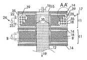
- FIG. 2is schematically an enlarged view of part AA′ of the filter unit of FIG. 1 .
- FIG. 3shows schematically a section according to the plane BB′ of the filter unit of FIG. 1 .
- FIG. 4shows schematically a side view of the contact bodies from a filter element as subject of the invention.
- FIG. 5shows schematically a view of alternative contact bodies from a filter element as subject of the invention.
- FIGS. 6 , 7 and 8show schematically a section according to the plane BB′ of an alternative embodiment of a filter unit as subject of the invention.
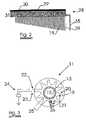
- FIG. 9shows a diesel exhaust filter system in a muffler-like shape, comprising different filter units as subject of the invention.
- FIGS. 1 , 2 and 3A preferred filter unit as subject of the invention is shown in FIGS. 1 , 2 and 3 .
- the filter unitcomprises a number of filter elements 11 , which are stacked one on top of the other. They all have a ring-like shape.
- a perforated metal tube 12is positioned inside the inner opening 13 of the filter element.
- a disc-like SiO 2 felt material 14is positioned to thermally insulate the different filter elements from each other.
- a metal plate 15is fixed against the upper and lower filter element e.g. as shown in FIG. 1 by means of a screw 16 , which pushes the plate towards the filter element. Between this plate 15 and the upper or lower filter element, another disc-like SiO 2 felt material 14 is positioned.
- the gas to be filteredflows in from the outer side of the filter elements (indicated with arrow 17 ), through the filter medium 18 through the perforations of the metal tube 12 , to the further exhaust system as indicated with arrow 19 .
- a metal fiber fleeceis used as filter medium 18 .
- the ‘dirty’ gasflows in via the inflow side 20 , through the metal fiber fleece, via the outflow side 21 of the metal fiber fleece to the exhaust system.
- the metal fiber fleeceis connected via two contact bodies 22 and 23 to an electric circuit 24 , providing electrical current to the metal fiber fleece in order to regenerate the dirt, e.g. soot, trapped in and on the filter medium.
- the metal fiber fleeceis preferably pleated in such a way that the thermal radiation heat, generated by the pleats 25 during regeneration, radiates to the adjacent pleats, as indicated by arrows 26 . An important reduction of electrical power is obtained using this radiation heat to propagate and support the combustion of the filtered particles
- a flank 28 of the filter elementcomprises a stiff material layer 29 , being a metal rim, in which an electrically and thermally insulating fabric 30 is located.
- This fabric 30preferably is a SiO 2 -feltlike material (e.g. non-woven), having a thickness of approximately 3 mm.
- the pleated edge of the metal fiber fleece 18is squeezed between two electrically and thermally insulated sides of the flanks as shown in FIG. 1 . When mounted, the metal fiber fleece 18 is pressed in the fabric 30 over a depth 31 of approximately 1 mm. This recess avoids the blow-through of the metal fiber fleece once the filter element is in use.
- studs 35may be welded to the upper and lower rim of each filter element.
- a perforated metal plate 39may be present (as only shown partially in the Figures for the sake of clarity).
- a fine Ni-sheet 36was sintered to the ends of the metal fiber fleece. Both contact bodies were brought together and fixed to an insulating plate 37 , e.g. a mica-plate by means of two bolts 38 and 39 . In order to avoid electrical contact between contact body 22 and bolt 38 , and between contact body 23 and bolt 39 , two mica sheets 40 were inserted between the insulating plate 37 and the contact bodies 22 and 23 .
- FIG. 5An alternative set-up is shown in FIG. 5 .
- An identical set-up as in FIG. 4is used, but the contact body 22 is shaped in such a way that no material of this contact body 22 is present at behind bolt 38 , fixing the contact body 23 to the insulating plate 37 .
- the contact body 23is shaped in such a way that no material of this contact body 23 is present at behind bolt 39 , fixing the contact body 22 to the insulating plate 37 .
- the use of two mica plates 40may be avoided, which may simplify the construction of the filter element.
- FIG. 6An alternative cut according to BB′ is shown in FIG. 6 .
- the perforated tube in this embodimenthas an elliptic section.
- the metal fiber fleeceis pleated according to pleating lines, which enables radiation from one pleat to another during regeneration.
- FIG. 7An other alternative cross section of a filter element as subject of the invention is shown in FIG. 7 .
- the filter element in this embodimentcomprises two metal fiber fleece strips, which together form the whole filter media of the filter element. Both metal fiber fleece strips have two contact bodies ( 22 and 23 ), at one end each, which are connected to an appropriate electric circuit 24 .
- FIG. 8Another alternative cross section of a filter element as subject of the invention is shown in FIG. 8 .
- the filter elementcomprises a set of metal fiber fleece strips, each being pleated over one pleating line 81 . All strips are mounted side by side.
- Each metal fiber fleece striphas two contact bodies ( 22 and 23 ), one at each end of the strip. The contact bodies are lined up and connected to an appropriate electric circuit 24 .
- gas to be filteredmay enter into a muffler system as shown in the FIG. 9 , via inlet 91 .
- Several filter units 92each comprising several filter elements 93 are present in the muffler-like system.
- the gas to be filteredgoes, as indicated with arrow 94 , through the filter media of each filter element and leaves the filter unit 92 via the perforated tube 95 in a collecting chamber 96 .
- the filtered exhaust gasflows further through the exhaust system as indicated with arrow 98 .
- a sintered metal fiber fleececomprising three layers of stainless steel fibers.
- a first layercomprises 600 g/m 2 of Fecralloy® fibers with equivalent diameter of 17 ⁇ m.
- a second layer of Fecralloy® fibersis applied on top of the first layer. This layer comprises 250 g/m 2 of fibers with equivalent diameter of 22 ⁇ m.
- a third layer of Fecralloy® fibersis applied on top of the second layer, having fibers with equivalent diameter of 35 ⁇ m. This third layer comprises 600 g/m 2 fibers.
- a soot retention of 91%was obtained, using a stainless steel fleece, having a porosity of 85%.
- the length of the metal fiber fleece in the above described embodimentsis preferably 1200 mm, while the height of the metal fiber fleece strip is preferably between 30 and 35 mm, e.g. 33,75 mm.
- the sootwas so-called depth filtered. This is to be understood as the fact that soot particles were trapped through the whole depth of the filter.
Landscapes
- Engineering & Computer Science (AREA)
- Chemical & Material Sciences (AREA)
- Combustion & Propulsion (AREA)
- Mechanical Engineering (AREA)
- General Engineering & Computer Science (AREA)
- Chemical Kinetics & Catalysis (AREA)
- Life Sciences & Earth Sciences (AREA)
- Geology (AREA)
- Ceramic Engineering (AREA)
- Inorganic Chemistry (AREA)
- Filtering Materials (AREA)
Abstract
Description
- 1. The filter medium, generating the thermal energy via Joule effects, looses thermal energy via radiation, e.g. towards the filter housing.
- 2. Thermal energy is lost via convection, heating the gasses which pas through the filter medium during regeneration. This effect is much larger when the strip is regenerated in stream.
- 3. Thermal energy is lost due to thermal conduction. E.g. when the filter medium is welded to the housing, a lot of thermal energy is transferred from the filter medium to the housing via this contact. The housing is needlessly heated by this thermal energy conducting.
Claims (11)
Priority Applications (1)
| Application Number | Priority Date | Filing Date | Title |
|---|---|---|---|
| US10/466,551US6991672B2 (en) | 2001-02-05 | 2002-01-31 | Filter element comprising pleated metal fiber fleece |
Applications Claiming Priority (4)
| Application Number | Priority Date | Filing Date | Title |
|---|---|---|---|
| US26590701P | 2001-02-05 | 2001-02-05 | |
| US60265907 | 2001-02-05 | ||
| US10/466,551US6991672B2 (en) | 2001-02-05 | 2002-01-31 | Filter element comprising pleated metal fiber fleece |
| PCT/EP2002/001159WO2002063147A2 (en) | 2001-02-05 | 2002-01-31 | Filter element comprising pleated metal fiber fleece |
Publications (2)
| Publication Number | Publication Date |
|---|---|
| US20040050022A1 US20040050022A1 (en) | 2004-03-18 |
| US6991672B2true US6991672B2 (en) | 2006-01-31 |
Family
ID=31996815
Family Applications (1)
| Application Number | Title | Priority Date | Filing Date |
|---|---|---|---|
| US10/466,551Expired - LifetimeUS6991672B2 (en) | 2001-02-05 | 2002-01-31 | Filter element comprising pleated metal fiber fleece |
Country Status (1)
| Country | Link |
|---|---|
| US (1) | US6991672B2 (en) |
Cited By (12)
| Publication number | Priority date | Publication date | Assignee | Title |
|---|---|---|---|---|
| US20040131511A1 (en)* | 2001-02-05 | 2004-07-08 | Willy Marrecau | Electrically regeneratable filter element |
| US20070111878A1 (en)* | 2005-11-16 | 2007-05-17 | Bilal Zuberi | Extrudable mixture for forming a porous block |
| US20070141255A1 (en)* | 2005-12-21 | 2007-06-21 | Bilal Zuberi | Method and apparatus for strengthening a porous substrate |
| US20070220871A1 (en)* | 2005-11-16 | 2007-09-27 | Bilal Zuberi | Method and Apparatus for Filtration of a Two-Stroke Engine Exhaust |
| US20080066621A1 (en)* | 2006-09-07 | 2008-03-20 | Nissin Electric Co., Ltd. | Particulate matter removal apparatus |
| US20080241014A1 (en)* | 2005-11-16 | 2008-10-02 | Geo2 Technologies, Inc. | Low coefficient of thermal expansion materials including modified aluminosilicate fibers and methods of manufacture |
| US20080242530A1 (en)* | 2005-11-16 | 2008-10-02 | Geo2 Technologies, Inc. | Low coefficient of thermal expansion materials including nonstoichiometric cordierite fibers and methods of manufacture |
| US20090000260A1 (en)* | 2005-11-16 | 2009-01-01 | Geo2 Technologies, Inc. | Fibrous Cordierite Materials |
| US20090035511A1 (en)* | 2007-07-31 | 2009-02-05 | Geo2 Technologies, Inc. | Fiber-Based Ceramic Substrate and Method of Fabricating the Same |
| US20090166910A1 (en)* | 2005-11-16 | 2009-07-02 | Geo2 Technologies, Inc. | System and Method for Twin Screw Extrusion of a Fibrous Porous Substrate |
| US20100048374A1 (en)* | 2005-11-16 | 2010-02-25 | James Jenq Liu | System and Method for Fabricating Ceramic Substrates |
| USRE48138E1 (en)* | 2001-02-05 | 2020-08-04 | Rypos, Inc. | Electrically regeneratable filter element |
Families Citing this family (3)
| Publication number | Priority date | Publication date | Assignee | Title |
|---|---|---|---|---|
| US7001449B2 (en)* | 2001-02-05 | 2006-02-21 | N.V. Bekaert S.A. | Diesel exhaust filter system with electrical regeneration |
| KR100950646B1 (en)* | 2003-10-16 | 2010-04-01 | 삼성전자주식회사 | Preamble Transmission Method for Synchronization of Multiplexed Orthogonal Frequency Division Multiplexing Systems |
| CN112742116A (en)* | 2020-12-31 | 2021-05-04 | 艾德曼金属材料(江阴)有限公司 | Ultrahigh-pressure metal fiber sintered felt and preparation method thereof |
Citations (16)
| Publication number | Priority date | Publication date | Assignee | Title |
|---|---|---|---|---|
| US3857688A (en)* | 1971-10-27 | 1974-12-31 | Ppg Industries Inc | Lead filter |
| US4199387A (en) | 1977-12-02 | 1980-04-22 | Cambridge Filter Corporation | Air filter fabrication method |
| US4687579A (en) | 1986-05-02 | 1987-08-18 | The United States Of America As Represented By The United States Department Of Energy | Sintered composite medium and filter |
| US5395039A (en)* | 1993-09-28 | 1995-03-07 | Pall Corporation | Method of making a filter assembly |
| US5405422A (en)* | 1991-09-20 | 1995-04-11 | Nippondenso Co., Ltd. | Self-heating filter |
| WO1997004152A1 (en) | 1995-07-14 | 1997-02-06 | N.V. Bekaert S.A. | Textile fabric comprising bundles of machined metal filaments |
| US5709722A (en) | 1995-05-30 | 1998-01-20 | Sumitomo Electric Industries, Ltd. | Particulate trap for diesel engine |
| US5733452A (en)* | 1995-04-21 | 1998-03-31 | Pall Corporation | Filter and end cap assembly including a porous layer for sealing with a potting material and method for making the assembly |
| US5800790A (en) | 1995-09-25 | 1998-09-01 | Sintokogio, Ltd. | Filter for treatment of carbon-based particles in exhaust gas and a device for said treatment using said filter |
| WO2000000721A1 (en)* | 1998-06-26 | 2000-01-06 | Pall Corporation | Internal combustion engine exhaust filters |
| US6096212A (en)* | 1997-06-10 | 2000-08-01 | Usf Filtration And Separations Group, Inc. | Fluid filter and method of making |
| WO2001000971A1 (en) | 1999-06-23 | 2001-01-04 | N.V. Bekaert S.A. | Diesel exhaust filter system with electrical regeneration |
| US6572682B2 (en)* | 2001-06-26 | 2003-06-03 | Rypos, Inc. | Self-cleaning filter system using direct electrically heated sintered metal fiber filter media |
| US20030196419A1 (en)* | 2002-04-18 | 2003-10-23 | Peter Klaus J. | Bifilar diesel exhaust filter construction using sintered metal fibers |
| US20040040268A1 (en) | 2001-02-05 | 2004-03-04 | Koen Wastijn | Diesel exhaust filter system with electrical regeneration |
| US20040050023A1 (en) | 2001-02-05 | 2004-03-18 | Koen Wastijn | Filter element |
- 2002
- 2002-01-31USUS10/466,551patent/US6991672B2/ennot_activeExpired - Lifetime
Patent Citations (17)
| Publication number | Priority date | Publication date | Assignee | Title |
|---|---|---|---|---|
| US3857688A (en)* | 1971-10-27 | 1974-12-31 | Ppg Industries Inc | Lead filter |
| US4199387A (en) | 1977-12-02 | 1980-04-22 | Cambridge Filter Corporation | Air filter fabrication method |
| US4687579A (en) | 1986-05-02 | 1987-08-18 | The United States Of America As Represented By The United States Department Of Energy | Sintered composite medium and filter |
| US5405422A (en)* | 1991-09-20 | 1995-04-11 | Nippondenso Co., Ltd. | Self-heating filter |
| US5395039A (en)* | 1993-09-28 | 1995-03-07 | Pall Corporation | Method of making a filter assembly |
| US5733452A (en)* | 1995-04-21 | 1998-03-31 | Pall Corporation | Filter and end cap assembly including a porous layer for sealing with a potting material and method for making the assembly |
| US5709722A (en) | 1995-05-30 | 1998-01-20 | Sumitomo Electric Industries, Ltd. | Particulate trap for diesel engine |
| WO1997004152A1 (en) | 1995-07-14 | 1997-02-06 | N.V. Bekaert S.A. | Textile fabric comprising bundles of machined metal filaments |
| US5800790A (en) | 1995-09-25 | 1998-09-01 | Sintokogio, Ltd. | Filter for treatment of carbon-based particles in exhaust gas and a device for said treatment using said filter |
| US6096212A (en)* | 1997-06-10 | 2000-08-01 | Usf Filtration And Separations Group, Inc. | Fluid filter and method of making |
| WO2000000721A1 (en)* | 1998-06-26 | 2000-01-06 | Pall Corporation | Internal combustion engine exhaust filters |
| WO2001000971A1 (en) | 1999-06-23 | 2001-01-04 | N.V. Bekaert S.A. | Diesel exhaust filter system with electrical regeneration |
| US20040040268A1 (en) | 2001-02-05 | 2004-03-04 | Koen Wastijn | Diesel exhaust filter system with electrical regeneration |
| US20040050023A1 (en) | 2001-02-05 | 2004-03-18 | Koen Wastijn | Filter element |
| US20040131511A1 (en) | 2001-02-05 | 2004-07-08 | Willy Marrecau | Electrically regeneratable filter element |
| US6572682B2 (en)* | 2001-06-26 | 2003-06-03 | Rypos, Inc. | Self-cleaning filter system using direct electrically heated sintered metal fiber filter media |
| US20030196419A1 (en)* | 2002-04-18 | 2003-10-23 | Peter Klaus J. | Bifilar diesel exhaust filter construction using sintered metal fibers |
Cited By (31)
| Publication number | Priority date | Publication date | Assignee | Title |
|---|---|---|---|---|
| US7267703B2 (en)* | 2001-02-05 | 2007-09-11 | Nv Bekaert Sa | Electrically regeneratable filter element |
| USRE48138E1 (en)* | 2001-02-05 | 2020-08-04 | Rypos, Inc. | Electrically regeneratable filter element |
| US20040131511A1 (en)* | 2001-02-05 | 2004-07-08 | Willy Marrecau | Electrically regeneratable filter element |
| US7486962B2 (en) | 2005-11-16 | 2009-02-03 | Geo2 Technologies, Inc. | Extruded porous substrate having inorganic bonds |
| US20090136709A1 (en)* | 2005-11-16 | 2009-05-28 | Bilal Zuberi | Extruded Porous Substrate having Inorganic Bonds |
| US20070111878A1 (en)* | 2005-11-16 | 2007-05-17 | Bilal Zuberi | Extrudable mixture for forming a porous block |
| US20070152364A1 (en)* | 2005-11-16 | 2007-07-05 | Bilal Zuberi | Process for extruding a porous substrate |
| US20070110645A1 (en)* | 2005-11-16 | 2007-05-17 | Bilal Zuberi | Extruded porous substrate having inorganic bonds |
| US20070220871A1 (en)* | 2005-11-16 | 2007-09-27 | Bilal Zuberi | Method and Apparatus for Filtration of a Two-Stroke Engine Exhaust |
| US8057568B2 (en) | 2005-11-16 | 2011-11-15 | Geo2 Technologies, Inc. | Extruded porous substrate and products using the same |
| US20080199369A1 (en)* | 2005-11-16 | 2008-08-21 | Geo2 Technologies, Inc. | Extruded porous substrate and products using the same |
| US20080241014A1 (en)* | 2005-11-16 | 2008-10-02 | Geo2 Technologies, Inc. | Low coefficient of thermal expansion materials including modified aluminosilicate fibers and methods of manufacture |
| US20080242530A1 (en)* | 2005-11-16 | 2008-10-02 | Geo2 Technologies, Inc. | Low coefficient of thermal expansion materials including nonstoichiometric cordierite fibers and methods of manufacture |
| US20090000260A1 (en)* | 2005-11-16 | 2009-01-01 | Geo2 Technologies, Inc. | Fibrous Cordierite Materials |
| US20070108647A1 (en)* | 2005-11-16 | 2007-05-17 | Bilal Zuberi | Method of forming a porous substrate having inorganic bonds |
| US8038759B2 (en) | 2005-11-16 | 2011-10-18 | Geoz Technologies, Inc. | Fibrous cordierite materials |
| US20070107395A1 (en)* | 2005-11-16 | 2007-05-17 | Bilal Zuberi | Extruded porous substrate and products using the same |
| US20090166910A1 (en)* | 2005-11-16 | 2009-07-02 | Geo2 Technologies, Inc. | System and Method for Twin Screw Extrusion of a Fibrous Porous Substrate |
| US20090173687A1 (en)* | 2005-11-16 | 2009-07-09 | Geo2 Technologies, Inc. | Extruded Porous Substrate and Products Using The Same |
| US7578865B2 (en) | 2005-11-16 | 2009-08-25 | Geo2 Technologies, Inc. | Method of forming a porous substrate having inorganic bonds |
| US7640732B2 (en) | 2005-11-16 | 2010-01-05 | Geo2 Technologies, Inc. | Method and apparatus for filtration of a two-stroke engine exhaust |
| US20100048374A1 (en)* | 2005-11-16 | 2010-02-25 | James Jenq Liu | System and Method for Fabricating Ceramic Substrates |
| US7938877B2 (en) | 2005-11-16 | 2011-05-10 | Geo2 Technologies, Inc. | Low coefficient of thermal expansion materials including modified aluminosilicate fibers and methods of manufacture |
| US7862641B2 (en) | 2005-11-16 | 2011-01-04 | Geo2 Technologies, Inc. | Extruded porous substrate and products using the same |
| US7901480B2 (en) | 2005-11-16 | 2011-03-08 | Geo2 Technologies, Inc. | Extruded porous substrate having inorganic bonds |
| US7938876B2 (en) | 2005-11-16 | 2011-05-10 | GE02 Technologies, Inc. | Low coefficient of thermal expansion materials including nonstoichiometric cordierite fibers and methods of manufacture |
| US8039050B2 (en) | 2005-12-21 | 2011-10-18 | Geo2 Technologies, Inc. | Method and apparatus for strengthening a porous substrate |
| US20070141255A1 (en)* | 2005-12-21 | 2007-06-21 | Bilal Zuberi | Method and apparatus for strengthening a porous substrate |
| US20080066621A1 (en)* | 2006-09-07 | 2008-03-20 | Nissin Electric Co., Ltd. | Particulate matter removal apparatus |
| US7781372B2 (en) | 2007-07-31 | 2010-08-24 | GE02 Technologies, Inc. | Fiber-based ceramic substrate and method of fabricating the same |
| US20090035511A1 (en)* | 2007-07-31 | 2009-02-05 | Geo2 Technologies, Inc. | Fiber-Based Ceramic Substrate and Method of Fabricating the Same |
Also Published As
| Publication number | Publication date |
|---|---|
| US20040050022A1 (en) | 2004-03-18 |
Similar Documents
| Publication | Publication Date | Title |
|---|---|---|
| EP1383990B1 (en) | Filter element comprising pleated metal fiber fleece | |
| US6991672B2 (en) | Filter element comprising pleated metal fiber fleece | |
| JP3000750B2 (en) | Self-heating filter | |
| US7980068B2 (en) | Woven metal fiber particulate filter | |
| US6024927A (en) | Particulate trap | |
| JP2732031B2 (en) | Exhaust particulate filter for diesel engine | |
| WO1998009059A1 (en) | Particulate trap for a diesel engine | |
| JPH0657288B2 (en) | Patty Yule Trap | |
| US7001449B2 (en) | Diesel exhaust filter system with electrical regeneration | |
| JPH10317945A (en) | Exhaust gas purification device | |
| USRE48138E1 (en) | Electrically regeneratable filter element | |
| JP3043543B2 (en) | Diesel Particulate Filter | |
| JPH1037739A (en) | Particulate trap device | |
| JPH06108823A (en) | Heat-resistant cylindrical filter | |
| JPH08303228A (en) | Particulate trap for diesel engine | |
| JPH06129228A (en) | Method and trapping micro particle in exhaust gas and filter therefor |
Legal Events
| Date | Code | Title | Description |
|---|---|---|---|
| AS | Assignment | Owner name:N.V. BEKAERT S.A., BELGIUM Free format text:ASSIGNMENT OF ASSIGNORS INTEREST;ASSIGNORS:MARRECAU, WILLY;WASTIJN, KOEN;DEVOOGHT, GEERT;REEL/FRAME:014456/0623;SIGNING DATES FROM 20030710 TO 20030717 | |
| STCF | Information on status: patent grant | Free format text:PATENTED CASE | |
| FPAY | Fee payment | Year of fee payment:4 | |
| AS | Assignment | Owner name:PROVENTIA EMISSION CONTROL OY, FINLAND Free format text:ASSIGNMENT OF ASSIGNORS INTEREST;ASSIGNOR:NV BEKAERT SA;REEL/FRAME:024678/0633 Effective date:20100303 | |
| FPAY | Fee payment | Year of fee payment:8 | |
| FPAY | Fee payment | Year of fee payment:12 | |
| AS | Assignment | Owner name:RYPOS, INC., MASSACHUSETTS Free format text:ASSIGNMENT OF ASSIGNORS INTEREST;ASSIGNOR:PROVENTIA OY;REEL/FRAME:048013/0937 Effective date:20190109 | |
| AS | Assignment | Owner name:MASSACHUSETTS CAPITAL RESOURCE COMPANY, MASSACHUSE Free format text:SECURITY INTEREST;ASSIGNOR:RYPOS, INC.;REEL/FRAME:048092/0624 Effective date:20170309 | |
| AS | Assignment | Owner name:RYPOS, INC., MASSACHUSETTS Free format text:ASSIGNMENT OF ASSIGNORS INTEREST;ASSIGNOR:PETER, KLAUS J;REEL/FRAME:048438/0517 Effective date:20120109 | |
| AS | Assignment | Owner name:RYPOS, INC., MASSACHUSETTS Free format text:ASSIGNMENT OF ASSIGNORS INTEREST;ASSIGNOR:IBRAHIM, OSAMA M;REEL/FRAME:048460/0457 Effective date:20190224 | |
| AS | Assignment | Owner name:SALEM FIVE CENTS SAVINGS BANK, MASSACHUSETTS Free format text:SECURITY INTEREST;ASSIGNOR:RYPOS, INC.;REEL/FRAME:057599/0757 Effective date:20210924 |