US6991656B2 - Method and apparatus for performing a minimally invasive total hip arthroplasty - Google Patents
Method and apparatus for performing a minimally invasive total hip arthroplastyDownload PDFInfo
- Publication number
- US6991656B2 US6991656B2US10/357,948US35794803AUS6991656B2US 6991656 B2US6991656 B2US 6991656B2US 35794803 AUS35794803 AUS 35794803AUS 6991656 B2US6991656 B2US 6991656B2
- Authority
- US
- United States
- Prior art keywords
- incision
- femoral
- rasp
- anterior
- posterior
- Prior art date
- Legal status (The legal status is an assumption and is not a legal conclusion. Google has not performed a legal analysis and makes no representation as to the accuracy of the status listed.)
- Expired - Lifetime, expires
Links
- 238000000034methodMethods0.000titleclaimsabstractdescription48
- 238000011882arthroplastyMethods0.000titleclaimsabstractdescription26
- 210000000689upper legAnatomy0.000claimsabstractdescription67
- 210000001624hipAnatomy0.000claimsabstractdescription61
- 210000000588acetabulumAnatomy0.000claimsabstractdescription21
- 210000002436femur neckAnatomy0.000abstractdescription45
- 238000002360preparation methodMethods0.000abstractdescription15
- 238000002513implantationMethods0.000abstractdescription2
- 210000002414legAnatomy0.000description44
- 239000007943implantSubstances0.000description28
- 238000003780insertionMethods0.000description26
- 230000037431insertionEffects0.000description26
- 210000001217buttockAnatomy0.000description16
- 239000002775capsuleSubstances0.000description16
- 210000000988bone and boneAnatomy0.000description11
- 238000005520cutting processMethods0.000description10
- 238000003032molecular dockingMethods0.000description10
- 230000036961partial effectEffects0.000description10
- 210000004394hip jointAnatomy0.000description8
- 210000004872soft tissueAnatomy0.000description8
- 230000007246mechanismEffects0.000description7
- 210000000109fascia lataAnatomy0.000description6
- 210000000527greater trochanterAnatomy0.000description6
- 230000001681protective effectEffects0.000description6
- 230000009467reductionEffects0.000description6
- 238000001356surgical procedureMethods0.000description6
- 238000012800visualizationMethods0.000description6
- 206010052428WoundDiseases0.000description5
- 208000027418Wounds and injuryDiseases0.000description5
- 210000003205muscleAnatomy0.000description5
- 206010033675panniculitisDiseases0.000description5
- 210000004304subcutaneous tissueAnatomy0.000description5
- 241000489861MaximusSpecies0.000description4
- 238000002224dissectionMethods0.000description4
- 239000000835fiberSubstances0.000description4
- 238000010276constructionMethods0.000description3
- 238000006073displacement reactionMethods0.000description3
- 230000000694effectsEffects0.000description3
- 239000002184metalSubstances0.000description3
- 230000037361pathwayEffects0.000description3
- 230000035479physiological effects, processes and functionsEffects0.000description3
- 238000013459approachMethods0.000description2
- 230000005540biological transmissionEffects0.000description2
- 230000001054cortical effectEffects0.000description2
- 238000013461designMethods0.000description2
- 210000003414extremityAnatomy0.000description2
- 238000005286illuminationMethods0.000description2
- 230000003116impacting effectEffects0.000description2
- 238000011065in-situ storageMethods0.000description2
- 230000003447ipsilateral effectEffects0.000description2
- 230000002262irrigationEffects0.000description2
- 238000003973irrigationMethods0.000description2
- 230000000670limiting effectEffects0.000description2
- 239000003550markerSubstances0.000description2
- 238000002324minimally invasive surgeryMethods0.000description2
- 230000008569processEffects0.000description2
- 230000002829reductive effectEffects0.000description2
- 210000002435tendonAnatomy0.000description2
- 210000001519tissueAnatomy0.000description2
- 206010020100Hip fractureDiseases0.000description1
- 239000004698PolyethyleneSubstances0.000description1
- 208000004550Postoperative PainDiseases0.000description1
- 241000283984RodentiaSpecies0.000description1
- 241000270295SerpentesSpecies0.000description1
- 241000469816VarusSpecies0.000description1
- 230000006978adaptationEffects0.000description1
- 230000003466anti-cipated effectEffects0.000description1
- 210000001367arteryAnatomy0.000description1
- 230000003115biocidal effectEffects0.000description1
- 230000000740bleeding effectEffects0.000description1
- 239000002639bone cementSubstances0.000description1
- 238000012790confirmationMethods0.000description1
- 238000007796conventional methodMethods0.000description1
- 210000000501femur bodyAnatomy0.000description1
- 210000003692iliumAnatomy0.000description1
- 208000014674injuryDiseases0.000description1
- 230000007794irritationEffects0.000description1
- 238000005304joiningMethods0.000description1
- 210000003127kneeAnatomy0.000description1
- 239000003589local anesthetic agentSubstances0.000description1
- 239000000463materialSubstances0.000description1
- 230000013011matingEffects0.000description1
- 230000001483mobilizing effectEffects0.000description1
- 230000007935neutral effectEffects0.000description1
- 238000002559palpationMethods0.000description1
- 210000004417patellaAnatomy0.000description1
- -1polyethylenePolymers0.000description1
- 229920000573polyethylenePolymers0.000description1
- 230000000750progressive effectEffects0.000description1
- 210000003689pubic boneAnatomy0.000description1
- 230000000541pulsatile effectEffects0.000description1
- 210000003314quadriceps muscleAnatomy0.000description1
- 238000011084recoveryMethods0.000description1
- 230000000717retained effectEffects0.000description1
- 230000037390scarringEffects0.000description1
- 238000004513sizingMethods0.000description1
- 239000007787solidSubstances0.000description1
- 238000011541total hip replacementMethods0.000description1
- 238000013519translationMethods0.000description1
- 230000008733traumaEffects0.000description1
- 210000003462veinAnatomy0.000description1
- 230000000007visual effectEffects0.000description1
- 239000013585weight reducing agentSubstances0.000description1
Images


Classifications
- B—PERFORMING OPERATIONS; TRANSPORTING
- B25—HAND TOOLS; PORTABLE POWER-DRIVEN TOOLS; MANIPULATORS
- B25B—TOOLS OR BENCH DEVICES NOT OTHERWISE PROVIDED FOR, FOR FASTENING, CONNECTING, DISENGAGING OR HOLDING
- B25B13/00—Spanners; Wrenches
- B25B13/48—Spanners; Wrenches for special purposes
- B25B13/481—Spanners; Wrenches for special purposes for operating in areas having limited access
- A—HUMAN NECESSITIES
- A61—MEDICAL OR VETERINARY SCIENCE; HYGIENE
- A61B—DIAGNOSIS; SURGERY; IDENTIFICATION
- A61B17/00—Surgical instruments, devices or methods
- A61B17/00234—Surgical instruments, devices or methods for minimally invasive surgery
- A—HUMAN NECESSITIES
- A61—MEDICAL OR VETERINARY SCIENCE; HYGIENE
- A61B—DIAGNOSIS; SURGERY; IDENTIFICATION
- A61B17/00—Surgical instruments, devices or methods
- A61B17/02—Surgical instruments, devices or methods for holding wounds open, e.g. retractors; Tractors
- A—HUMAN NECESSITIES
- A61—MEDICAL OR VETERINARY SCIENCE; HYGIENE
- A61B—DIAGNOSIS; SURGERY; IDENTIFICATION
- A61B17/00—Surgical instruments, devices or methods
- A61B17/14—Surgical saws
- A61B17/15—Guides therefor
- A—HUMAN NECESSITIES
- A61—MEDICAL OR VETERINARY SCIENCE; HYGIENE
- A61B—DIAGNOSIS; SURGERY; IDENTIFICATION
- A61B17/00—Surgical instruments, devices or methods
- A61B17/14—Surgical saws
- A61B17/15—Guides therefor
- A61B17/151—Guides therefor for corrective osteotomy
- A—HUMAN NECESSITIES
- A61—MEDICAL OR VETERINARY SCIENCE; HYGIENE
- A61B—DIAGNOSIS; SURGERY; IDENTIFICATION
- A61B17/00—Surgical instruments, devices or methods
- A61B17/16—Instruments for performing osteoclasis; Drills or chisels for bones; Trepans
- A61B17/164—Instruments for performing osteoclasis; Drills or chisels for bones; Trepans intramedullary
- A—HUMAN NECESSITIES
- A61—MEDICAL OR VETERINARY SCIENCE; HYGIENE
- A61B—DIAGNOSIS; SURGERY; IDENTIFICATION
- A61B17/00—Surgical instruments, devices or methods
- A61B17/16—Instruments for performing osteoclasis; Drills or chisels for bones; Trepans
- A61B17/1659—Surgical rasps, files, planes, or scrapers
- A—HUMAN NECESSITIES
- A61—MEDICAL OR VETERINARY SCIENCE; HYGIENE
- A61B—DIAGNOSIS; SURGERY; IDENTIFICATION
- A61B17/00—Surgical instruments, devices or methods
- A61B17/16—Instruments for performing osteoclasis; Drills or chisels for bones; Trepans
- A61B17/1662—Instruments for performing osteoclasis; Drills or chisels for bones; Trepans for particular parts of the body
- A61B17/1664—Instruments for performing osteoclasis; Drills or chisels for bones; Trepans for particular parts of the body for the hip
- A61B17/1668—Instruments for performing osteoclasis; Drills or chisels for bones; Trepans for particular parts of the body for the hip for the upper femur
- A—HUMAN NECESSITIES
- A61—MEDICAL OR VETERINARY SCIENCE; HYGIENE
- A61B—DIAGNOSIS; SURGERY; IDENTIFICATION
- A61B17/00—Surgical instruments, devices or methods
- A61B17/16—Instruments for performing osteoclasis; Drills or chisels for bones; Trepans
- A61B17/17—Guides or aligning means for drills, mills, pins or wires
- A61B17/1735—Guides or aligning means for drills, mills, pins or wires for rasps or chisels
- A—HUMAN NECESSITIES
- A61—MEDICAL OR VETERINARY SCIENCE; HYGIENE
- A61B—DIAGNOSIS; SURGERY; IDENTIFICATION
- A61B17/00—Surgical instruments, devices or methods
- A61B17/16—Instruments for performing osteoclasis; Drills or chisels for bones; Trepans
- A61B17/17—Guides or aligning means for drills, mills, pins or wires
- A61B17/1739—Guides or aligning means for drills, mills, pins or wires specially adapted for particular parts of the body
- A61B17/1742—Guides or aligning means for drills, mills, pins or wires specially adapted for particular parts of the body for the hip
- A61B17/175—Guides or aligning means for drills, mills, pins or wires specially adapted for particular parts of the body for the hip for preparing the femur for hip prosthesis insertion
- A—HUMAN NECESSITIES
- A61—MEDICAL OR VETERINARY SCIENCE; HYGIENE
- A61B—DIAGNOSIS; SURGERY; IDENTIFICATION
- A61B17/00—Surgical instruments, devices or methods
- A61B17/34—Trocars; Puncturing needles
- A61B17/3417—Details of tips or shafts, e.g. grooves, expandable, bendable; Multiple coaxial sliding cannulas, e.g. for dilating
- A61B17/3421—Cannulas
- A—HUMAN NECESSITIES
- A61—MEDICAL OR VETERINARY SCIENCE; HYGIENE
- A61F—FILTERS IMPLANTABLE INTO BLOOD VESSELS; PROSTHESES; DEVICES PROVIDING PATENCY TO, OR PREVENTING COLLAPSING OF, TUBULAR STRUCTURES OF THE BODY, e.g. STENTS; ORTHOPAEDIC, NURSING OR CONTRACEPTIVE DEVICES; FOMENTATION; TREATMENT OR PROTECTION OF EYES OR EARS; BANDAGES, DRESSINGS OR ABSORBENT PADS; FIRST-AID KITS
- A61F2/00—Filters implantable into blood vessels; Prostheses, i.e. artificial substitutes or replacements for parts of the body; Appliances for connecting them with the body; Devices providing patency to, or preventing collapsing of, tubular structures of the body, e.g. stents
- A61F2/02—Prostheses implantable into the body
- A61F2/30—Joints
- A61F2/46—Special tools for implanting artificial joints
- A61F2/4603—Special tools for implanting artificial joints for insertion or extraction of endoprosthetic joints or of accessories thereof
- A61F2/4607—Special tools for implanting artificial joints for insertion or extraction of endoprosthetic joints or of accessories thereof of hip femoral endoprostheses
- A—HUMAN NECESSITIES
- A61—MEDICAL OR VETERINARY SCIENCE; HYGIENE
- A61F—FILTERS IMPLANTABLE INTO BLOOD VESSELS; PROSTHESES; DEVICES PROVIDING PATENCY TO, OR PREVENTING COLLAPSING OF, TUBULAR STRUCTURES OF THE BODY, e.g. STENTS; ORTHOPAEDIC, NURSING OR CONTRACEPTIVE DEVICES; FOMENTATION; TREATMENT OR PROTECTION OF EYES OR EARS; BANDAGES, DRESSINGS OR ABSORBENT PADS; FIRST-AID KITS
- A61F2/00—Filters implantable into blood vessels; Prostheses, i.e. artificial substitutes or replacements for parts of the body; Appliances for connecting them with the body; Devices providing patency to, or preventing collapsing of, tubular structures of the body, e.g. stents
- A61F2/02—Prostheses implantable into the body
- A61F2/30—Joints
- A61F2/46—Special tools for implanting artificial joints
- A61F2/4603—Special tools for implanting artificial joints for insertion or extraction of endoprosthetic joints or of accessories thereof
- A61F2/4609—Special tools for implanting artificial joints for insertion or extraction of endoprosthetic joints or of accessories thereof of acetabular cups
- A—HUMAN NECESSITIES
- A61—MEDICAL OR VETERINARY SCIENCE; HYGIENE
- A61F—FILTERS IMPLANTABLE INTO BLOOD VESSELS; PROSTHESES; DEVICES PROVIDING PATENCY TO, OR PREVENTING COLLAPSING OF, TUBULAR STRUCTURES OF THE BODY, e.g. STENTS; ORTHOPAEDIC, NURSING OR CONTRACEPTIVE DEVICES; FOMENTATION; TREATMENT OR PROTECTION OF EYES OR EARS; BANDAGES, DRESSINGS OR ABSORBENT PADS; FIRST-AID KITS
- A61F2/00—Filters implantable into blood vessels; Prostheses, i.e. artificial substitutes or replacements for parts of the body; Appliances for connecting them with the body; Devices providing patency to, or preventing collapsing of, tubular structures of the body, e.g. stents
- A61F2/02—Prostheses implantable into the body
- A61F2/30—Joints
- A61F2/46—Special tools for implanting artificial joints
- A61F2/4684—Trial or dummy prostheses
- A—HUMAN NECESSITIES
- A61—MEDICAL OR VETERINARY SCIENCE; HYGIENE
- A61G—TRANSPORT, PERSONAL CONVEYANCES, OR ACCOMMODATION SPECIALLY ADAPTED FOR PATIENTS OR DISABLED PERSONS; OPERATING TABLES OR CHAIRS; CHAIRS FOR DENTISTRY; FUNERAL DEVICES
- A61G13/00—Operating tables; Auxiliary appliances therefor
- A61G13/0036—Orthopaedic operating tables
- B—PERFORMING OPERATIONS; TRANSPORTING
- B25—HAND TOOLS; PORTABLE POWER-DRIVEN TOOLS; MANIPULATORS
- B25B—TOOLS OR BENCH DEVICES NOT OTHERWISE PROVIDED FOR, FOR FASTENING, CONNECTING, DISENGAGING OR HOLDING
- B25B13/00—Spanners; Wrenches
- B25B13/02—Spanners; Wrenches with rigid jaws
- B25B13/06—Spanners; Wrenches with rigid jaws of socket type
- B—PERFORMING OPERATIONS; TRANSPORTING
- B25—HAND TOOLS; PORTABLE POWER-DRIVEN TOOLS; MANIPULATORS
- B25B—TOOLS OR BENCH DEVICES NOT OTHERWISE PROVIDED FOR, FOR FASTENING, CONNECTING, DISENGAGING OR HOLDING
- B25B13/00—Spanners; Wrenches
- B25B13/48—Spanners; Wrenches for special purposes
- B—PERFORMING OPERATIONS; TRANSPORTING
- B25—HAND TOOLS; PORTABLE POWER-DRIVEN TOOLS; MANIPULATORS
- B25B—TOOLS OR BENCH DEVICES NOT OTHERWISE PROVIDED FOR, FOR FASTENING, CONNECTING, DISENGAGING OR HOLDING
- B25B7/00—Pliers; Other hand-held gripping tools with jaws on pivoted limbs; Details applicable generally to pivoted-limb hand tools
- B25B7/02—Jaws
- A—HUMAN NECESSITIES
- A61—MEDICAL OR VETERINARY SCIENCE; HYGIENE
- A61B—DIAGNOSIS; SURGERY; IDENTIFICATION
- A61B17/00—Surgical instruments, devices or methods
- A61B17/02—Surgical instruments, devices or methods for holding wounds open, e.g. retractors; Tractors
- A61B17/0293—Surgical instruments, devices or methods for holding wounds open, e.g. retractors; Tractors with ring member to support retractor elements
- A—HUMAN NECESSITIES
- A61—MEDICAL OR VETERINARY SCIENCE; HYGIENE
- A61B—DIAGNOSIS; SURGERY; IDENTIFICATION
- A61B17/00—Surgical instruments, devices or methods
- A61B17/56—Surgical instruments or methods for treatment of bones or joints; Devices specially adapted therefor
- A61B17/58—Surgical instruments or methods for treatment of bones or joints; Devices specially adapted therefor for osteosynthesis, e.g. bone plates, screws or setting implements
- A61B17/88—Osteosynthesis instruments; Methods or means for implanting or extracting internal or external fixation devices
- A61B17/8866—Osteosynthesis instruments; Methods or means for implanting or extracting internal or external fixation devices for gripping or pushing bones, e.g. approximators
- A—HUMAN NECESSITIES
- A61—MEDICAL OR VETERINARY SCIENCE; HYGIENE
- A61B—DIAGNOSIS; SURGERY; IDENTIFICATION
- A61B17/00—Surgical instruments, devices or methods
- A61B17/56—Surgical instruments or methods for treatment of bones or joints; Devices specially adapted therefor
- A61B17/58—Surgical instruments or methods for treatment of bones or joints; Devices specially adapted therefor for osteosynthesis, e.g. bone plates, screws or setting implements
- A61B17/88—Osteosynthesis instruments; Methods or means for implanting or extracting internal or external fixation devices
- A61B17/8872—Instruments for putting said fixation devices against or away from the bone
- A—HUMAN NECESSITIES
- A61—MEDICAL OR VETERINARY SCIENCE; HYGIENE
- A61B—DIAGNOSIS; SURGERY; IDENTIFICATION
- A61B17/00—Surgical instruments, devices or methods
- A61B2017/0046—Surgical instruments, devices or methods with a releasable handle; with handle and operating part separable
- A—HUMAN NECESSITIES
- A61—MEDICAL OR VETERINARY SCIENCE; HYGIENE
- A61B—DIAGNOSIS; SURGERY; IDENTIFICATION
- A61B90/00—Instruments, implements or accessories specially adapted for surgery or diagnosis and not covered by any of the groups A61B1/00 - A61B50/00, e.g. for luxation treatment or for protecting wound edges
- A61B90/08—Accessories or related features not otherwise provided for
- A61B2090/0801—Prevention of accidental cutting or pricking
- A61B2090/08021—Prevention of accidental cutting or pricking of the patient or his organs
- A—HUMAN NECESSITIES
- A61—MEDICAL OR VETERINARY SCIENCE; HYGIENE
- A61F—FILTERS IMPLANTABLE INTO BLOOD VESSELS; PROSTHESES; DEVICES PROVIDING PATENCY TO, OR PREVENTING COLLAPSING OF, TUBULAR STRUCTURES OF THE BODY, e.g. STENTS; ORTHOPAEDIC, NURSING OR CONTRACEPTIVE DEVICES; FOMENTATION; TREATMENT OR PROTECTION OF EYES OR EARS; BANDAGES, DRESSINGS OR ABSORBENT PADS; FIRST-AID KITS
- A61F2/00—Filters implantable into blood vessels; Prostheses, i.e. artificial substitutes or replacements for parts of the body; Appliances for connecting them with the body; Devices providing patency to, or preventing collapsing of, tubular structures of the body, e.g. stents
- A61F2/0095—Packages or dispensers for prostheses or other implants
- A—HUMAN NECESSITIES
- A61—MEDICAL OR VETERINARY SCIENCE; HYGIENE
- A61F—FILTERS IMPLANTABLE INTO BLOOD VESSELS; PROSTHESES; DEVICES PROVIDING PATENCY TO, OR PREVENTING COLLAPSING OF, TUBULAR STRUCTURES OF THE BODY, e.g. STENTS; ORTHOPAEDIC, NURSING OR CONTRACEPTIVE DEVICES; FOMENTATION; TREATMENT OR PROTECTION OF EYES OR EARS; BANDAGES, DRESSINGS OR ABSORBENT PADS; FIRST-AID KITS
- A61F2/00—Filters implantable into blood vessels; Prostheses, i.e. artificial substitutes or replacements for parts of the body; Appliances for connecting them with the body; Devices providing patency to, or preventing collapsing of, tubular structures of the body, e.g. stents
- A61F2/02—Prostheses implantable into the body
- A61F2/30—Joints
- A61F2/32—Joints for the hip
- A61F2/34—Acetabular cups
- A—HUMAN NECESSITIES
- A61—MEDICAL OR VETERINARY SCIENCE; HYGIENE
- A61F—FILTERS IMPLANTABLE INTO BLOOD VESSELS; PROSTHESES; DEVICES PROVIDING PATENCY TO, OR PREVENTING COLLAPSING OF, TUBULAR STRUCTURES OF THE BODY, e.g. STENTS; ORTHOPAEDIC, NURSING OR CONTRACEPTIVE DEVICES; FOMENTATION; TREATMENT OR PROTECTION OF EYES OR EARS; BANDAGES, DRESSINGS OR ABSORBENT PADS; FIRST-AID KITS
- A61F2/00—Filters implantable into blood vessels; Prostheses, i.e. artificial substitutes or replacements for parts of the body; Appliances for connecting them with the body; Devices providing patency to, or preventing collapsing of, tubular structures of the body, e.g. stents
- A61F2/02—Prostheses implantable into the body
- A61F2/30—Joints
- A61F2/32—Joints for the hip
- A61F2/36—Femoral heads ; Femoral endoprostheses
- A—HUMAN NECESSITIES
- A61—MEDICAL OR VETERINARY SCIENCE; HYGIENE
- A61F—FILTERS IMPLANTABLE INTO BLOOD VESSELS; PROSTHESES; DEVICES PROVIDING PATENCY TO, OR PREVENTING COLLAPSING OF, TUBULAR STRUCTURES OF THE BODY, e.g. STENTS; ORTHOPAEDIC, NURSING OR CONTRACEPTIVE DEVICES; FOMENTATION; TREATMENT OR PROTECTION OF EYES OR EARS; BANDAGES, DRESSINGS OR ABSORBENT PADS; FIRST-AID KITS
- A61F2/00—Filters implantable into blood vessels; Prostheses, i.e. artificial substitutes or replacements for parts of the body; Appliances for connecting them with the body; Devices providing patency to, or preventing collapsing of, tubular structures of the body, e.g. stents
- A61F2/02—Prostheses implantable into the body
- A61F2/30—Joints
- A61F2/46—Special tools for implanting artificial joints
- A61F2/4603—Special tools for implanting artificial joints for insertion or extraction of endoprosthetic joints or of accessories thereof
- A—HUMAN NECESSITIES
- A61—MEDICAL OR VETERINARY SCIENCE; HYGIENE
- A61F—FILTERS IMPLANTABLE INTO BLOOD VESSELS; PROSTHESES; DEVICES PROVIDING PATENCY TO, OR PREVENTING COLLAPSING OF, TUBULAR STRUCTURES OF THE BODY, e.g. STENTS; ORTHOPAEDIC, NURSING OR CONTRACEPTIVE DEVICES; FOMENTATION; TREATMENT OR PROTECTION OF EYES OR EARS; BANDAGES, DRESSINGS OR ABSORBENT PADS; FIRST-AID KITS
- A61F2/00—Filters implantable into blood vessels; Prostheses, i.e. artificial substitutes or replacements for parts of the body; Appliances for connecting them with the body; Devices providing patency to, or preventing collapsing of, tubular structures of the body, e.g. stents
- A61F2/02—Prostheses implantable into the body
- A61F2/30—Joints
- A61F2002/30001—Additional features of subject-matter classified in A61F2/28, A61F2/30 and subgroups thereof
- A61F2002/30667—Features concerning an interaction with the environment or a particular use of the prosthesis
- A61F2002/30718—Means for protecting prosthetic parts, e.g. during operation
- A—HUMAN NECESSITIES
- A61—MEDICAL OR VETERINARY SCIENCE; HYGIENE
- A61F—FILTERS IMPLANTABLE INTO BLOOD VESSELS; PROSTHESES; DEVICES PROVIDING PATENCY TO, OR PREVENTING COLLAPSING OF, TUBULAR STRUCTURES OF THE BODY, e.g. STENTS; ORTHOPAEDIC, NURSING OR CONTRACEPTIVE DEVICES; FOMENTATION; TREATMENT OR PROTECTION OF EYES OR EARS; BANDAGES, DRESSINGS OR ABSORBENT PADS; FIRST-AID KITS
- A61F2/00—Filters implantable into blood vessels; Prostheses, i.e. artificial substitutes or replacements for parts of the body; Appliances for connecting them with the body; Devices providing patency to, or preventing collapsing of, tubular structures of the body, e.g. stents
- A61F2/02—Prostheses implantable into the body
- A61F2/30—Joints
- A61F2/32—Joints for the hip
- A61F2/34—Acetabular cups
- A61F2002/3401—Acetabular cups with radial apertures, e.g. radial bores for receiving fixation screws
- A61F2002/3403—Polar aperture
- A—HUMAN NECESSITIES
- A61—MEDICAL OR VETERINARY SCIENCE; HYGIENE
- A61F—FILTERS IMPLANTABLE INTO BLOOD VESSELS; PROSTHESES; DEVICES PROVIDING PATENCY TO, OR PREVENTING COLLAPSING OF, TUBULAR STRUCTURES OF THE BODY, e.g. STENTS; ORTHOPAEDIC, NURSING OR CONTRACEPTIVE DEVICES; FOMENTATION; TREATMENT OR PROTECTION OF EYES OR EARS; BANDAGES, DRESSINGS OR ABSORBENT PADS; FIRST-AID KITS
- A61F2/00—Filters implantable into blood vessels; Prostheses, i.e. artificial substitutes or replacements for parts of the body; Appliances for connecting them with the body; Devices providing patency to, or preventing collapsing of, tubular structures of the body, e.g. stents
- A61F2/02—Prostheses implantable into the body
- A61F2/30—Joints
- A61F2/32—Joints for the hip
- A61F2/36—Femoral heads ; Femoral endoprostheses
- A61F2/3609—Femoral heads or necks; Connections of endoprosthetic heads or necks to endoprosthetic femoral shafts
- A61F2002/3611—Heads or epiphyseal parts of femur
- A61F2002/3621—Heads or epiphyseal parts of femur pierced with a longitudinal bore
- A—HUMAN NECESSITIES
- A61—MEDICAL OR VETERINARY SCIENCE; HYGIENE
- A61F—FILTERS IMPLANTABLE INTO BLOOD VESSELS; PROSTHESES; DEVICES PROVIDING PATENCY TO, OR PREVENTING COLLAPSING OF, TUBULAR STRUCTURES OF THE BODY, e.g. STENTS; ORTHOPAEDIC, NURSING OR CONTRACEPTIVE DEVICES; FOMENTATION; TREATMENT OR PROTECTION OF EYES OR EARS; BANDAGES, DRESSINGS OR ABSORBENT PADS; FIRST-AID KITS
- A61F2/00—Filters implantable into blood vessels; Prostheses, i.e. artificial substitutes or replacements for parts of the body; Appliances for connecting them with the body; Devices providing patency to, or preventing collapsing of, tubular structures of the body, e.g. stents
- A61F2/02—Prostheses implantable into the body
- A61F2/30—Joints
- A61F2/32—Joints for the hip
- A61F2/36—Femoral heads ; Femoral endoprostheses
- A61F2/3609—Femoral heads or necks; Connections of endoprosthetic heads or necks to endoprosthetic femoral shafts
- A61F2002/3625—Necks
- A—HUMAN NECESSITIES
- A61—MEDICAL OR VETERINARY SCIENCE; HYGIENE
- A61F—FILTERS IMPLANTABLE INTO BLOOD VESSELS; PROSTHESES; DEVICES PROVIDING PATENCY TO, OR PREVENTING COLLAPSING OF, TUBULAR STRUCTURES OF THE BODY, e.g. STENTS; ORTHOPAEDIC, NURSING OR CONTRACEPTIVE DEVICES; FOMENTATION; TREATMENT OR PROTECTION OF EYES OR EARS; BANDAGES, DRESSINGS OR ABSORBENT PADS; FIRST-AID KITS
- A61F2/00—Filters implantable into blood vessels; Prostheses, i.e. artificial substitutes or replacements for parts of the body; Appliances for connecting them with the body; Devices providing patency to, or preventing collapsing of, tubular structures of the body, e.g. stents
- A61F2/02—Prostheses implantable into the body
- A61F2/30—Joints
- A61F2/46—Special tools for implanting artificial joints
- A61F2/4603—Special tools for implanting artificial joints for insertion or extraction of endoprosthetic joints or of accessories thereof
- A61F2002/4622—Special tools for implanting artificial joints for insertion or extraction of endoprosthetic joints or of accessories thereof having the shape of a forceps or a clamp
- A—HUMAN NECESSITIES
- A61—MEDICAL OR VETERINARY SCIENCE; HYGIENE
- A61F—FILTERS IMPLANTABLE INTO BLOOD VESSELS; PROSTHESES; DEVICES PROVIDING PATENCY TO, OR PREVENTING COLLAPSING OF, TUBULAR STRUCTURES OF THE BODY, e.g. STENTS; ORTHOPAEDIC, NURSING OR CONTRACEPTIVE DEVICES; FOMENTATION; TREATMENT OR PROTECTION OF EYES OR EARS; BANDAGES, DRESSINGS OR ABSORBENT PADS; FIRST-AID KITS
- A61F2/00—Filters implantable into blood vessels; Prostheses, i.e. artificial substitutes or replacements for parts of the body; Appliances for connecting them with the body; Devices providing patency to, or preventing collapsing of, tubular structures of the body, e.g. stents
- A61F2/02—Prostheses implantable into the body
- A61F2/30—Joints
- A61F2/46—Special tools for implanting artificial joints
- A61F2/4603—Special tools for implanting artificial joints for insertion or extraction of endoprosthetic joints or of accessories thereof
- A61F2002/4625—Special tools for implanting artificial joints for insertion or extraction of endoprosthetic joints or of accessories thereof with relative movement between parts of the instrument during use
- A61F2002/4628—Special tools for implanting artificial joints for insertion or extraction of endoprosthetic joints or of accessories thereof with relative movement between parts of the instrument during use with linear motion along or rotating motion about an axis transverse to the instrument axis or to the implantation direction, e.g. clamping
- A—HUMAN NECESSITIES
- A61—MEDICAL OR VETERINARY SCIENCE; HYGIENE
- A61F—FILTERS IMPLANTABLE INTO BLOOD VESSELS; PROSTHESES; DEVICES PROVIDING PATENCY TO, OR PREVENTING COLLAPSING OF, TUBULAR STRUCTURES OF THE BODY, e.g. STENTS; ORTHOPAEDIC, NURSING OR CONTRACEPTIVE DEVICES; FOMENTATION; TREATMENT OR PROTECTION OF EYES OR EARS; BANDAGES, DRESSINGS OR ABSORBENT PADS; FIRST-AID KITS
- A61F2/00—Filters implantable into blood vessels; Prostheses, i.e. artificial substitutes or replacements for parts of the body; Appliances for connecting them with the body; Devices providing patency to, or preventing collapsing of, tubular structures of the body, e.g. stents
- A61F2/02—Prostheses implantable into the body
- A61F2/30—Joints
- A61F2/46—Special tools for implanting artificial joints
- A61F2/4603—Special tools for implanting artificial joints for insertion or extraction of endoprosthetic joints or of accessories thereof
- A61F2002/4629—Special tools for implanting artificial joints for insertion or extraction of endoprosthetic joints or of accessories thereof connected to the endoprosthesis or implant via a threaded connection
- A—HUMAN NECESSITIES
- A61—MEDICAL OR VETERINARY SCIENCE; HYGIENE
- A61F—FILTERS IMPLANTABLE INTO BLOOD VESSELS; PROSTHESES; DEVICES PROVIDING PATENCY TO, OR PREVENTING COLLAPSING OF, TUBULAR STRUCTURES OF THE BODY, e.g. STENTS; ORTHOPAEDIC, NURSING OR CONTRACEPTIVE DEVICES; FOMENTATION; TREATMENT OR PROTECTION OF EYES OR EARS; BANDAGES, DRESSINGS OR ABSORBENT PADS; FIRST-AID KITS
- A61F2/00—Filters implantable into blood vessels; Prostheses, i.e. artificial substitutes or replacements for parts of the body; Appliances for connecting them with the body; Devices providing patency to, or preventing collapsing of, tubular structures of the body, e.g. stents
- A61F2/02—Prostheses implantable into the body
- A61F2/30—Joints
- A61F2/46—Special tools for implanting artificial joints
- A61F2002/4635—Special tools for implanting artificial joints using minimally invasive surgery
- A—HUMAN NECESSITIES
- A61—MEDICAL OR VETERINARY SCIENCE; HYGIENE
- A61F—FILTERS IMPLANTABLE INTO BLOOD VESSELS; PROSTHESES; DEVICES PROVIDING PATENCY TO, OR PREVENTING COLLAPSING OF, TUBULAR STRUCTURES OF THE BODY, e.g. STENTS; ORTHOPAEDIC, NURSING OR CONTRACEPTIVE DEVICES; FOMENTATION; TREATMENT OR PROTECTION OF EYES OR EARS; BANDAGES, DRESSINGS OR ABSORBENT PADS; FIRST-AID KITS
- A61F2/00—Filters implantable into blood vessels; Prostheses, i.e. artificial substitutes or replacements for parts of the body; Appliances for connecting them with the body; Devices providing patency to, or preventing collapsing of, tubular structures of the body, e.g. stents
- A61F2/02—Prostheses implantable into the body
- A61F2/30—Joints
- A61F2/46—Special tools for implanting artificial joints
- A61F2002/4681—Special tools for implanting artificial joints by applying mechanical shocks, e.g. by hammering
Definitions
- the present inventionrelates to total hip arthroplasty, and, more particularly, to a method and apparatus for performing a minimally invasive total hip arthroplasty.
- Orthopaedic procedures for the replacement of all, or a portion of, a patient's jointhave been developed over the last 30 years.
- the procedures used to prepare the bone and seat the implantsare generally referred to as open procedures.
- the term open procedurewill refer to a procedure wherein an incision is made through the skin and underlying tissue to fully expose a large portion of the particular joint surface.
- the typical incision requiredis approximately 25 centimeters (10 inches) long.
- the internal woundmay be enlarged in order to fully expose the areas to be prepared.
- the underlying damage to the soft tissuecan lengthen a patient's rehabilitation time after surgery. While the implants may be well fixed at the time of surgery, it may be several weeks or perhaps months before the soft tissues violated during surgery can be fully healed.
- the present inventionprovides an improved method and apparatus for performing a minimally invasive total hip arthroplasty.
- a total hip arthroplastycan be performed in accordance with the teachings of the current invention utilizing two incisions with the size of each of the wounds developed on the surface being substantially constant throughout the depth of the wound.
- the first incisionis an anterior incision approximately 3.75-5 centimeters (1.5-2 inches) in length made in line with the femoral neck and the central axis of the acetabulum.
- the second incisionis a posterior incision approximately 2.5-3.75 centimeters (1-1.5 inches) positioned to be generally in axial alignment with the femoral shaft.
- the anterior incisionbegins at the intertrochanteric ridge and is extended inferiorly and medially generally on the line along which the femoral neck will be severed from the femur.
- the anterior incisionis made in line with the Langer's lines in the skin and therefore leads to less scarring.
- the posterior incisionis aligned with the femoral shaft and is generally colinear with the anterior incision. In this way, the anterior incision and the posterior incision can be connected to allow for an open procedure in the event that a minimally invasive procedure is planned but an open procedure is determined to be necessary.
- the femoral headis severed from the femoral shaft and removed through the anterior incision.
- the acetabular cupis placed in the acetabulum through the anterior incision, while the posterior incision is used to prepare the femoral shaft to receive a femoral stem.
- a femoral stemis inserted through the posterior incision and positioned in the femoral shaft. Procedures performed through the posterior incision may be observed through the anterior incision and vice versa.
- a total hip arthroplastyis defined as a replacement of the femoral head with or without the use of a separate acetabular component.
- the specific designs which can be utilized in accordance with the present inventioninclude a total hip replacement and a bipolar or monopolar endo prosthesis.
- the techniqueis suitable for cemented or cementless anchorage of the components.
- the apparatus and method of the current inventionadvantageously allow a total hip arthroplasty to be performed in a minimally invasive way, which hastens patient recovery.
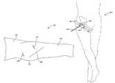
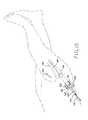
- FIG. 1Ais a side elevational view of a patient illustrating a pair of incisions made according to the current invention as well as the incision utilized in prior art procedures;
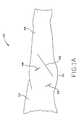
- FIG. 1Bis a side elevational view of a patient illustrating an alternative pair of incisions made according to the current invention as well as a line joining the incision pair along which a third incision can be made to join the incision pair and convert the procedure from a minimally invasive procedure to an open procedure;
- FIG. 2Ais an anterior elevational view of a hip joint illustrating the femoral neck axis
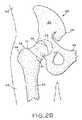
- FIG. 2Bis an anterior elevational view of a hip joint illustrating the line along which the femoral neck will be severed from the femur and further illustrating the location of anterior incision 44 ′ depicted in FIG. 1B ;
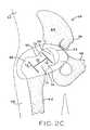
- FIG. 2Cis an anterior elevational view illustrating the capsule of the hip joint
- FIG. 3is an anterior elevational view of the femoral neck exposed by incising the hip capsule;
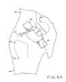
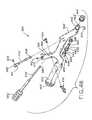
- FIG. 4is an anterior elevational view of the femoral neck with an osteotomy guide of one form of the current invention operably positioned to designate a cut line thereon;
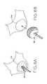
- FIG. 5Ais a side elevational view of an alternative embodiment of an osteotomy guide in accordance with the present invention.
- FIG. 5Bis an elevational view thereof taken along the longitudinal axis of the handle
- FIG. 6Ais an anterior elevational view illustrating the femoral head and neck severed along the cut line indicated by the osteotomy guide;
- FIG. 6Bis an anterior elevational view illustrating the femoral head and neck severed along the cut line illustrated in FIG. 2 B and further illustrating the line along which the femoral head is severed from the femoral neck in accordance with one embodiment of the present invention
- FIG. 7is an anterior elevational view illustrating the removal of a portion of the femoral head and neck
- FIGS. 8A and 8Billustrate preparation of the acetabulum to receive the acetabular cup
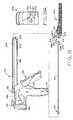
- FIG. 9is a side elevational view of an acetabular cup inserter relative to a patient lying in the supine position
- FIG. 10is an anterior elevational view of a portion of the cup inserter illustrated in FIG. 9 and a patient lying in the supine position;
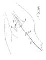
- FIG. 11is a side elevational view illustrating the use of a curved awl to locate a posterior incision
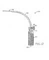
- FIG. 12is a side elevational, partial sectional view of an awl in accordance with the present invention.
- FIG. 13is a perspective view illustrating the insertion of a posterior retractor in the posterior incision
- FIG. 14is a perspective, exploded view of one embodiment of a tubular retractor in accordance with the present invention.
- FIG. 14Ais a side elevational view of an alternative embodiment of the tubular retractor
- FIG. 15is a perspective view illustrating the insertion of a guide wire into the tubular retractor
- FIG. 16is a perspective view illustrating reaming of the femoral shaft
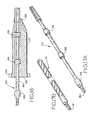
- FIG. 17Ais a perspective view of an end cutter
- FIG. 17Bis a perspective view of a femoral reamer
- FIG. 18is a side elevational, partial sectional view of an end cutter inserted into a tubular retractor of the present invention.
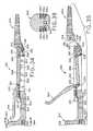
- FIG. 19is a perspective view of a rasp handle after inserting a rasp into the femoral shaft
- FIG. 19Ais a perspective view illustrating an inserted rasp, with the rasp handle removed, and with the cable used to affix the rasp to the rasp handle protruding from the posterior incision;
- FIGS. 20A and 20Bare partial sectional views of the rasp handle
- FIG. 21is an exploded view of the rasp handle and a rasp to be connected thereto;
- FIG. 21Ais a partial elevational view along line 21 A— 21 A of FIG. 21 ;
- FIG. 22is a perspective view illustrating placement of a provisional neck of the present invention.
- FIG. 23is a perspective view of the provisional neck and mating forceps of the present invention.
- FIG. 24Ais a partial sectional, radial elevational view of the provisional neck
- FIGS. 24B and 24Care radial elevational views thereof
- FIG. 25is a perspective view illustrating the insertion of a femoral stem with a protective bag through the posterior incision
- FIG. 26is a perspective view illustrating alignment of the femoral stem while observing through the anterior incision
- FIG. 27illustrates an incision into the femoral stem protective bag prior to insertion of the femoral stem into the femoral shaft
- FIG. 28is a perspective view illustrating removal of the femoral stem protective bag while inserting the femoral stem, with observation through the anterior incision;
- FIG. 29is a perspective view of a femoral stem insertion tool in accordance with the teachings of the present invention.
- FIG. 30is a perspective view of a hip prosthesis which can be implanted according to the method of the current invention.
- FIG. 31is a perspective view of an alternative embodiment rasp handle in accordance with the present invention.
- FIG. 32is a side elevational view thereof
- FIG. 33is a top elevational view thereof
- FIG. 34is a sectional view illustrating a rasp secured to the rasp handle
- FIG. 35is a sectional view illustrating release of the locking mechanism used to secure a rasp to the rasp handle
- FIG. 36is a sectional view of the impaction surface of the rasp handle illustrated in FIGS. 31-35 ;
- FIG. 37is an exploded perspective view of a cup inserter of the present invention.
- FIG. 38is a side plan view thereof.
- FIG. 39is a partial sectional view of the distal portion of the frame of the cup inserter illustrated in FIGS. 37 and 38 ;
- FIG. 40is a sectional view of a threaded shaft used to engage an acetabular cup in conjunction with the cup inserter illustrated in FIGS. 37 and 38 ;
- FIG. 41is a sectional view thereof
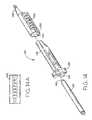
- FIG. 42is a side elevational view of a connecting shaft of the cup inserter illustrated in FIGS. 37 and 38 ;
- FIG. 43is a sectional view thereof
- FIG. 44is an end elevational view thereof
- FIG. 45Ais a sectional view taken along line 45 A- 45 A of FIG. 42 ;
- FIG. 45Bis a sectional view taken along line 45 B- 45 B of FIG. 42 ;
- FIG. 46is an exploded perspective view of another acetabular cup inserter in accordance with the present invention.
- FIG. 47is a radial elevational view of a threaded shaft used to engage an acetabular cup in conjunction with the cup inserter illustrated in FIG. 46 ;
- FIG. 48is an axial elevational view thereof
- FIG. 49is a radial elevational view of a U-joint linkage in accordance with the present invention.
- FIG. 50is a second radial elevational view thereof, rotated 90° with respect to FIG. 49 ;
- FIG. 51is a top elevational view of a locking lever in accordance with the present invention.
- FIG. 52is a side elevational view thereof
- FIG. 53is a radial elevational view of a locking shaft in accordance with the present invention.
- FIG. 54is a sectional view thereof taken along line 54 - 54 of FIG. 53 ;
- FIG. 55is an axial elevational view of the locking shaft depicted in FIG. 53 ;
- FIG. 56is a perspective view of an operating table in accordance with the present invention.
- FIG. 57is a top elevational view thereof
- FIG. 58is a side elevational view thereof
- FIG. 59is a side elevational view thereof illustrating a patient positioned atop the operating table of the present invention.
- FIG. 60is a side elevational view of the operating table of the present invention illustrating use of a buttocks door to allow for extension of the patient's buttocks through the table top;
- FIG. 61is a side elevational view illustrating rotation of a leg panel of the operating table of the present invention to allow for hyperextension of the patient's hip;
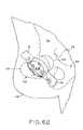
- FIG. 62is an anterior elevational view of the osteotomized femoral neck viewed through an anterior incision made in accordance with the present invention, with the operative leg placed in hyperextension;
- FIG. 63is radial elevational view of a lateralizing reamer of the present invention.
- proximal and distalare sometimes used to refer to opposite ends of instruments described herein.
- proximal and distalare used with reference to a user of the instrument. For example, the end of the instrument nearest the user during use thereof is described as the proximal end, while the end of the instrument farthest from the user during use is described as the distal end of the instrument.
- a total hip arthroplastycan be performed, according to the teachings of the current invention through two incisions, each no more than 5 centimeters (2 inches) in length.
- An anterior incisionis made either along the axis of the femoral neck or aligned with the line along which the femur will be osteotomized to remove the femoral neck, while a posterior incision is made generally in axial alignment with the femoral shaft.
- FIG. 1Aa partial illustration of patient 40 including torso 52 , buttock 50 , and leg 48 illustrates prior art incision 42 as well as exemplary anterior incision 44 and exemplary posterior incision 46 of the current invention.
- Prior art incision 42is approximately 25 centimeters (10 inches) long, while anterior incision 44 and posterior incision 46 are each no more than 5 centimeters (2 inches) in length.
- FIG. 1Ba partial illustration of patient 40 ′ including torso 52 ′, buttock 50 ′, and leg 48 ′ is used to illustrate exemplary anterior incision 44 ′ and exemplary posterior incision 46 ′ of the current invention.
- Anterior incision 44 ′ and posterior incision 46 ′are each no more than 5 centimeters (2 inches) in length.
- anterior incision 44 ′ and posterior incision 46 ′are generally colinear and can be joined along line 47 to allow for a minimally invasive hip procedure to be altered to an open procedure.
- patient 40is initially placed in a supine position on an operating table.
- a standard operating table or a radiolucent tablecan be used.
- operating table 400 illustrated in FIGS. 56-61is utilized.
- Operating table 400includes a table top which is completely radiolucent, i.e., no portion of the table top of operating table 400 is radiopaque.
- Operating table 400will be described in further detail hereinbelow.
- a radiolucent tableis preferred if the surgical team intends to use intraoperative image intensification.
- fluoroscopic imagesare taken repeatedly taken throughout the procedure to confirm proper positioning of instruments, and implants.
- endoscopic imagescan be taken.
- a Storz viewsite endoscopic systemprovides a sterile viewing screen for endoscopic images.
- the sterile viewing screen of a Storz viewsite endoscopic systemcan be positioned within the surgical field immediately adjacent to anterior incision 44 or 44 ′.
- Other known endoscopic systemsmay further be utilized during the total hip arthroplasty of the present invention.
- anterior superior iliac spine (ASIS) 59two prominent bony landmarks are palpated, anterior superior iliac spine (ASIS) 59 and greater trochanter 58 of femur 62 .
- Ilium 64 and pubis 66 of hip 68are shown to better illustrate the relevant area of the body.
- the approximate anterior incision starting point 71is identified two fingerbreadths inferior and two fingerbreadths anterior to the tubercle of the greater trochanter 58 .
- the approximate finish point for the anterior incisionis identified three fingerbreadths inferior and two fingerbreadths lateral to the anterior superior iliac spine (ASIS) 59 .
- the approximate anterior incision starting point 71is identified 3-4 centimeters inferior and 2 centimeters lateral to ASIS 59 . Having identified starting point 71 3-4 centimeters inferior and 2 centimeters lateral to ASIS 59 , the path of anterior incision 44 is extended obliquely from starting point 71 toward the prominence of greater trochanter 58 along the axis of femoral neck 60 . With the use of a spinal needle, the appropriate starting point 71 and the path of the anterior incision can be identified by impaling the skin down to bone to confirm the central axis 70 of femoral neck 60 .
- a metal, or other radiopaque markercan be positioned over the identified path of anterior incision 44 and a fluroscopic image taken to confirm the appropriate position of anterior incision 44 .
- anterior incision 44 ′FIG. 1B
- starting point 71 ′FIG. 2B
- the position of intertrochanteric ridge 59can be confirmed by impaling the skin down to the bone with, e.g., a spinal needle.
- the location of anterior incision 44 ′can further be confirmed by placing a metallic or otherwise radiopaque instrument over line 61 illustrated in FIG. 2 B and taking a fluoroscopic image.
- a surgical markercan be utilized to mark the location of same on the patient's skin.
- anterior incision 44an oblique incision of approximately 3.75-5 centimeters (1.5-2 inches) is made from the starting site 71 toward the prominence of the greater trochanter along the axis 70 of the femoral neck 60 and the central axis of acetabulum 54 to form anterior incision 44 as illustrated, e.g., in FIG. 1 A.
- anterior incision 44 ′an oblique incision of approximately 3.75-5.0 centimeters (1.5-2.0 inches) is made from starting site 71 ′ and extended obliquely along line 61 illustrated in FIG. 2 B.
- the anterior incision ( 44 or 44 ′)is extended along the same plane through subcutaneous tissues, exposing the underlying fascia lata.
- the internervous plane between the tensor fascia lata muscle and the sartoriusis identified by palpation and developed by curved scissors and blunt dissection.
- the sartoriuscan be made more prominent by externally rotating the leg to apply tension on the muscle.
- Deep to the tensor fascia lata and the sartoriusis an internervous interval between the rectus femoris and the gluteus medius. This plane is developed by blunt dissection.
- a lateral retraction of the tensor fascia latapermits a visualization of the capsule 74 of the hip joint as illustrated in FIG. 2 C. In this way, the hip capsule is exposed without requiring the incision of muscle.
- the indirect head of the rectus femoruswill be taken down to expose the hip capsule, but it is generally very easy to elevate the rectus femorus from the capsule without damaging it and expose the hip capsule with no violation of muscle.
- the precapsular fat and lateral circumflex vessel that travels across the front of the capsuleare exposed.
- the circumflex vesselsmay present as one or 2 larger arteries and veins, or multiple smaller vessels. If the circumflex vessels are relatively large, they can be ligated to prevent bleeding during reaming of the acetabulum. If they are smaller, they can be cauterized.
- Capsule 74is incised along the axis 70 ( FIG. 2A ) of femoral neck 60 from the equator of femoral head 56 to the intertrochanteric ridge of femur 62 .
- the capsular incisiontakes the form of an “H-shaped” window formed by incisions 72 (FIG. 2 C). The H-shaped window is formed by adding supplementary perpendicular limbs around the equator of femoral head 56 and the base of femoral neck 60 to the initial incision along the axis 70 of femoral neck 60 .
- retractors 76are placed inside capsular flaps 73 and underneath the superior and inferior borders of femoral neck 60 to expose the entire length of femoral neck 60 from the inferior aspect of femoral head 56 to the intertrochanteric ridge.
- Retractors 76can be, e.g., Cobra retractors.
- each retractorhouses a light source and can also serve to anchor an endoscope. Retractors 76 thereby provide continuous visualization and illumination of the wound.
- JAKOSCOPE retractors having integral fiberoptic light sourcesare utilized in accordance with present invention.
- a femoral cutting tool 86e.g., a reciprocating saw, oscillating saw or a power burr is used to excise femoral neck 60 .
- a custom osteotomy guide 78can be placed through anterior incision 44 ( FIG. 1A ) or 44 ′ ( FIG. 1B ) to guide the femoral neck cut.
- Alignment portion 82 of osteotomy guide 78is aligned with the longitudinal axis of femur 62 , while cut guide 84 is positioned on femoral neck 60 .
- Handle 80 of osteotomy guide 78facilitates positioning and repositioning of osteotomy guide 78 through anterior incision 44 or 44 ′.
- osteotomy guide 78After placement of osteotomy guide 78 , cut line 85 is scored as is known in the art. Osteotomy guide 78 is thereafter removed through anterior incision 44 or 44 ′ and femoral cutting tool 86 is inserted through anterior incision 44 or 44 ′ and utilized to cut along cut line 85 and displace portion 88 ( FIGS. 6A and 6B ) from femur 62 . If anterior incision 44 ′ is utilized, it will be aligned with the osteotomy utilized to displace portion 88 from femur 62 . In this way, anterior incision 44 ′ may allow for less soft tissue irritation when osteotomizing cut portion 88 from femur 62 because the oscillating saw will move in line with anterior incision 44 ′.
- Retractors 76are repositioned around the anterior and posterior rims of the acetabulum.
- a custom curved cutting tooli.e., the “ligamentum teres cutter” is passed behind femoral head 56 to sharply incise the ligamentum teres, thus mobilizing cut portion 88 as illustrated in FIG. 6 A.
- Cut portion 88includes femoral head 56 as well as a portion of femoral neck 60 (FIG. 4 ). Cut portion 88 is thereafter removed through anterior incision 44 with a custom femoral head bone grasper 94 (FIG. 7 ). If there is difficulty removing cut portion 88 in one piece, it may be in situ morselized using cutting tool 87 (FIG.
- Morsels 92may then be removed through anterior incision 44 as illustrated in FIG. 7 . Morselizing of cut portion 88 can be accomplished making cuts which substantially mirror the cuts in hip capsule 74 .
- a corkscrew and hip skidremoves the entire femoral neck, as in hip fracture.
- femoral head 56is severed along cut line 63 ( FIG. 6B ) prior to incising the ligamentum teres.
- the osteotomized femoral neckis removed before incising the ligamentum teres.
- femoral head 56may be in situ to morselized to facilitate removal thereof as necessary.
- a threaded Steinman pin or a Shanz screwcan be utilized to remove the osteotomized femoral neck and head.
- Irrigation and suction devicescan be used to cool the bone and facilitate the removal of bony debris in hip capsule 74 .
- a fiberoptic endoscopeis placed into the hip joint to confirm the complete removal of bony debris.
- the fibro-fatty tissue within the cotyloid fossa of acetabulum 54is removed with the use of, e.g., high-speed acorn-tipped cutting tool 96 , Rongeur forceps, and a curette. Thereafter, the acetabular labrum can be trimmed with a scalpel. As illustrated in FIG. 8B , acetabulum 54 is then progressively reamed with standard acetabular reamer 98 . In an alternative embodiment, a customized minimally invasive reamer such as the one disclosed in co-pending U.S. patent application Ser. No.
- Acetabular reamers within a predetermined size rangeare utilized until the optimal size of the acetabulum is reached. Sizing of the acetabulum is facilitated by the use of pre-operative templates and radiographs as is known in the art.
- a fluoroscope, or endoscopecan be used to aid in visualization during the reaming process. In certain instances, multiple fluoroscopic or endoscopic images are taken during the reaming process to confirm that when reaming is complete the reamer is bottomed out and is concentric with the acetabulum.
- acetabulumis under reamed by approximately 2 mm with respect to the diameter of the anticipated acetabular cup so as to create an interference fit.
- High speed acorn-shaped cutting tool 96 , and acetabular reamer 98enter the body through anterior incision 44 or 44 ′.
- a press-fit acetabular cup of the appropriate sizecan be firmly seated with cup inserter 100 as illustrated in FIG. 9 and impacted into the acetabular recess as is known in the art.
- acetabular cup inserters 360 , 360 ′may be utilized to seat an appropriate acetabular cup. Cup inserters 360 and 360 ′ are further described hereinbelow. If a balloon is positioned under the hip and inflated during the total hip arthroplasty of the present invention, it can be deflated when determining proper alignment for seating of the acetabular implant.
- Acceptable press fit acetabular cupsinclude the ZIMMER HGP II or TRILOGY cups.
- Proper positioning of the acetabular cupcan be achieved with a custom anteflexion and pelvic alignment guide as illustrated in FIG. 9 A.
- Patient 40is placed in supine position on operating table 102 .
- Aligning rod 104is aligned with the mid lateral axis of torso 52 while main shaft 105 is maintained approximately 30° from operating table 102 for proper seating of the acetabular cup.
- a flexible drillcan be used to guide the placement of one or more acetabular screws. In some cases, acetabular screws will not be necessary.
- the insertion of the acetabular lineris, in certain embodiments, deferred until the proximal femur has been prepared for the insertion of a trial stem.
- patient 40remains in the supine position on operating table 102 (FIG. 9 ) while cup inserter 100 is utilized to seat the acetabular cup.
- patient 40remains in the supine position on operating table 102 if either of cup inserters 360 , 360 ′ are utilized to seat the acetabular cup.
- a pade.g., an inflatable pad placed under the ipsilateral hip.
- an inflatable padis placed under the hip and inflated at the beginning of the procedure. With an inflatable pad in place under the hip and inflated, the femur will drop below the acetabulum when the femoral neck is osteotomized giving better access to both the acetabulum and the femur.
- the operative hipis slightly flexed or extended, adducted approximately 30° to 45°, and maximally externally rotated or rotated to approximately 30° to 45°.
- an operating table having movable leg panelsis utilized.
- the non-operative legcan be dropped below the operative leg prior to position the operative hip for preparation of the femur (e.g., extending, adducting, and rotating the operative hip).
- the operative hipis effectively raised, which facilitates preparation of the femur as described below.
- Retractors 76are repositioned around the medial and lateral aspects of femur 62 .
- a self-retaining retractor with a light source attachment and an endoscope holdercan be positioned in anterior incision 44 to provide constant visualization and illumination of femur 62 .
- the soft tissues along the anterior surface of femur 62 just inferior to the intertrochanteric ridgeare subperiosteally reflected with a scalpel or curved osteotome to expose the bone for a width of approximately 1 cm. This sharp subperiosteal elevation continues superolaterally onto the anterior margin of the greater trochanter. Then with curved Mayo scissors a pathway is developed by blunt dissection that is directed superficially to the anterior fibers of the gluteus minimus towards buttock 50 (FIG. 11 ).
- the osteotomized femoral neckis visualized through the anterior incision and any remaining superolateral femoral neck is removed.
- Curved Mayo scissorsare then directed posterior to the posterior neck of the femur just superior to the insertion of the piriformis tendon. If the piriformis tendon traverses this site, it is divided with the scissors. the scissors are advanced through the posterior capsule and toward the gluteus maximus. To assist in the direction of the scissors, a line can be drawn along the front axis of the femur and along the side axis. Where the two lines intersect on the superolateral aspect of the hip is the appropriate site for the posterior as is further described herein below.
- awl 106is inserted through anterior incision 44 , directed through the cleft between the gluteus maximus in line with the shaft of the femur and piriformis fossae region, and advanced into the soft tissues of buttock 50 until its pointed distal end 108 can be palpated on the surface of the skin.
- Distal end 108 of awl 106is generally aligned with the longitudinal axis of femur 62 .
- posterior incision 46 or 46 ′of approximately 2-3 cm (0.8-1.2 inches) is made and extended through the subcutaneous tissues and fascia lata to expose the underlying gluteus maximus.
- a surgical marking pencan be used to draw a line on the skin down the front of the femur and a line on the skin along the side of the femur. The intersection of these two lines will generally mark the position of the posterior incision.
- a tract to femur 62is developed along the path created by awl 106 .
- the gluteus maximusis split bluntly in line with its fibers with curved Mayo scissors.
- Finger dissectionmay be utilized to reach the posterior piriformis fossa region. In certain cases the piriformis obstructs the view of the femur. In these cases, the piriformis can be divided.
- elliptical posterior retractor 122In many instances, the piriformis is inferior to the femur and does not require division.
- custom elliptical posterior retractor 122can be threaded ( FIG. 13 ) down to the osteotomized femoral neck.
- elliptical posterior retractor 122includes posterior lip 128 (FIG. 14 ). In this embodiment, retractor 122 is threaded down to the osteotomized femoral neck until posterior lip 128 lies beneath the posterior intertrochanteric ridge.
- FIG. 14Aillustrates an embodiment of rasp tunnel 130 without posterior lip 128 .
- each component of posterior retractor 122i.e., guide tube 124 , reamer tunnel 126 , and rasp tunnel 130
- each individual tunnelmay be provided with a posterior lip similar to posterior lip 128 illustrated in FIG. 14 .
- no posterior retractoris utilized. Rasping and reaming of the femur will now be described. The posterior capsule will be entered to facilitate rasping and reaming of the femur. Any step performed through a tubular retractor positioned in the posterior may be performed through the posterior incision without a retractor positioned therein.
- a straight pointed awlis inserted into the posterior incision while observing its progress through the anterior incision.
- the awlis inserted into the osteotomized femoral neck and advanced manually down the femoral canal.
- a ball tipped guide wireis inserted through the posterior incision into the osteotomized femoral neck down the femoral canal.
- ball tipped guide wire 146is inserted through guide tube 124 of posterior retractor 122 and advanced into femoral canal 148 . While FIG. 15 illustrates guide tube 124 nested in reamer tunnel 126 and rasp tunnel 130 , guide tube 124 may be directly inserted through posterior incision 46 or 46 ′, or not used. In one exemplary embodiment, ball-tipped guide wire 146 is directly inserted through posterior incision 46 or 46 ′ and advanced into femoral canal 148 .
- a conical cannulated reamer or end millis used to prepare the femoral metaphysis. If a nested posterior retractor configuration is utilized, guide tube 124 must be removed so that the reamer can be inserted through reamer tunnel 126 of posterior retractor 122 . Similarly, if a nested configuration is not utilized, reamer tunnel 126 can be inserted into posterior incision 46 if the surgeon chooses to use it. In any event, ball tipped guide wire 146 is inserted about halfway down femoral canal 148 .
- the following detailed description of the inventionmakes reference to a nested posterior retractor configuration.
- each individual component of posterior retractor 122can be inserted and removed through posterior incision 46 as necessary. Moreover, if no tubular posterior retractors are utilized, then the following steps can be performed by placing instruments directly through posterior incision 46 or 46 ′.
- FIG. 16illustrates preparation of femoral canal 148 to receive rasp 204 (FIG. 19 ).
- Guide tube 124is removed from posterior retractor 122 and end cutter 150 ( FIG. 17A ) is inserted through reamer tunnel 126 .
- FIG. 18illustrates end cutter 150 positioned within reamer tunnel 126 .
- End cutter 150includes elongate aperture 160 through which guide wire 146 passes and guides end cutter 150 .
- End cutter 150is actuated by any of the many actuating devices known in the art. After end cutting is complete, end cutter 150 is removed through reamer tunnel 126 and reamer 151 ( FIG. 17B ) is inserted therethrough.
- Reamer 151includes reamer guide aperture 161 through which guide wire 146 passes and guides reamer 151 as it reams femoral canal 148 . Reamers of progressive increase in their outer diameter are sequentially placed over guide wire 146 and femoral canal 148 is reamed until cortical “chatter” is felt. As is known in the art, the optimal diameter of femoral canal 148 is provisionally determined by preoperative templating. Some surgeons may choose to avoid reaming of the femoral shaft and instead utilize a broach as is known in the art. A broach may be inserted in accordance with the current invention as described hereinbelow with respect to rasp insertion. In one exemplary embodiment, lateralizing reamers are utilized to prepare femoral canal 148 .
- reaming of femoral canal 148begins with the use of a flexible reamer.
- the flexible reameris used to enlarge the femoral canal along its normal axis.
- a cannulated flexibleis utilized.
- the flexible reameris positioned over the inserted ball tip guide wire.
- lateralizing reamer 480is inserted through posterior incision 46 and into the femoral canal.
- Lateralizing reamer 480is a blunt tipped side cutting reamer.
- Lateralizing reamer 480is utilized to remove bone stock into the greater trochanter so that the implanted femoral stem will be coaxial with the shaft of femur 62 and will not be aligned in varus. Stated another way, lateralizing reamer 480 is used to side cut the femoral canal to move the top of the pathway posteriorward allow for proper implantation of the prosthetic femoral component. If a taper fit stem is utilized, then reaming is complete after using the lateralizing reamer. If a fully coated porous stem is utilized, then a straight solid reamer such as the VERSYS reamer available from Zimmer, Inc. is utilized to continue reaming the femoral canal.
- a number of reamers of increasing sizecan be utilized.
- a first flexible reamercan be utilized to ream out the femoral canal, followed by a second flexible reamer larger in size than the first flexible reamer.
- reamer tunnel 126( FIG. 14 ) is removed from posterior retractor 122 so that rasp 204 and rasp handle 212 ( FIG. 19 ) can be inserted over guide wire 146 to complete preparation of femur 62 .
- Guide wire 146is inserted into rasp guide aperture 214 and rasp handle guide aperture 202 to guide rasp 204 to prepared femur 62 .
- Impact surface 164is struck, as is known in the art, to place rasp 204 in femur 62 . While rasp 204 is being impacted, the rotational alignment can be assessed by direct visual scrutiny of femur 62 through anterior incision 44 .
- rasp handle 212With respect to the patella, lower leg, and foot facilitates alignment.
- a flattened area of anterior boneprovides a highly reproducable landmark for the rotational alignment. This may not be true if the patient has experienced prior surgery or trauma.
- rasp handle 212is removed along with guide wire 146 and posterior retractor 122 , leaving distal end 208 of flexible cable 192 ( FIG. 19A ) attached to the proximal end of rasp 204 and proximal end 194 of flexible cable 192 protruding from posterior incision 46 .
- the operation of rasp handle 212will be further explained below.
- rasp handle 300 illustrated in FIGS. 31-36is utilized. Rasp handle 300 can be utilized with a VERSYS rasp available from Zimmer, Inc. The operation of rasp handle 300 and its cooperation with a femoral rasp will be further described hereinbelow.
- One or more fluoroscopic imagescan be utilized to ensure proper orientation and position of the femoral rasps.
- a trial acetabular lineris placed through anterior incision 44 or 44 ′ and into the seated acetabular cup with the use of a liner inserter as is known in the art.
- a trial or final acetabular linercan be seated in the seated acetabular cup prior to preparation of femur 62 .
- Provisional neck 222( FIGS. 23 , and 24 A-C) is inserted through anterior incision 44 and locked to the top end of the seated rasp, as illustrated in FIG. 22.
- a trial femoral headis placed on the Morse taper of provisional neck 222 through anterior incision 44 .
- the hip jointis reduced for an assessment of stability of the hip joint and limb length. Where necessary, a second assessment is made.
- the hipis dislocated and the provisional head and provisional neck 222 are removed.
- Rasp handle 212is reinserted through posterior incision 46 over the free end of flexible cable 192 .
- Rasp handle 212is advanced until it can be locked with the seated rasp so that impact surface 164 can be impacted and the entire tool (i.e., rasp 204 and rasp handle 212 ) can be removed.
- the trial acetabular lineris removed through anterior incision 44 .
- a trial reductioncan be performed utilizing the final femoral implant and a trial femoral head.
- a trial femoral headsuch as the one disclosed in U.S. patent application Ser. No. 09/992,639 filed Nov. 6, 2001 and published as U.S. Publication No. US2002/0099447 A1, the disclosure of which is hereby explicitly incorporated by reference herein.
- Femoral implant 238( FIG. 30 ) is anchored to femoral stem insertion tool 240 ( FIG. 29 ) and placed through posterior incision 46 or 46 ′.
- Femoral implant 238can be, e.g., a VERSYS fiber metal taper, a VERSYS fiber metal midcoat, or a VERSYS full coat stem available from Zimmer, Inc.
- femoral implant 238is placed in protective, disposable bag 242 prior to its introduction into posterior incision 46 or 46 ′.
- FIG. 25illustrates femoral implant 238 oriented as it will be when placed in femur 62 .
- femoral implant 238can be rotated 180° from this position to prevent impingement on the body.
- Femoral implant 238is then rotated 180° after being completely inserted through posterior incision 46 . Similar rotations of femoral implant 238 can be made when utilizing posterior incision 46 ′.
- FIG. 26illustrates femoral stem 238 and bag 242 inserted through posterior incision 46 .
- the tip of femoral stem 238approaches the osteotomized femoral neck, the distal end of bag 242 is incised as illustrated in FIG. 27 .
- Scalpel 246is inserted into anterior incision 44 to incise bag 242 .
- bag 242is progressively removed through posterior incision 46 as illustrated in FIG. 28 .
- femoral stem insertion tool 240FIG. 29
- anterior incision 44Through anterior incision 44 , the final femoral head is positioned on the femoral neck Morse taper using a standard holding device and secured with a standard impaction tool and mallet. The hip is then reduced and assessed for stability. While described with reference to anterior incision 44 and posterior incision 46 , this method of seating femoral stem 238 is equally applicable when using anterior incision 44 ′ and posterior incision 46 ′.
- the hip capsule and the soft tissuesare repaired with heavy sutures or staples.
- a suitable local anesthetic solutionis injected into the closed hip joint as well as the capsular layer and the subcutaneous tissues, allowing superior postoperative pain relief.
- the fascial layers, subcutaneous tissues, and skin of both the anterior and posterior woundsare closed in a conventional method and dressings are applied.
- a suction drainmay be used at the discretion of the surgeon.
- Osteotomy guide 78illustrated in use in FIG. 4 , includes handle 80 , alignment portion 82 , and cut guide 84 .
- cut guide 84 and alignment portion 82form a 60° angle.
- alignment portion 82includes a tapered distal end as illustrated in FIGS. 5A and 5B .
- Osteotomy guide 78is inserted through anterior incision 44 and is positioned with alignment portion 82 placed on femur 62 so that alignment portion 82 generally aligns with the longitudinal axis of femur 62 .
- Handle 80protrudes through anterior incision 44 and may be utilized to position osteotomy guide 78 .
- osteotomy guide 78is utilized to mark cut line 85 on femoral neck 60 as illustrated in FIG. 4 .
- Osteotomy guide 78can be formed to function on either side of the body.
- FIG. 4illustrates an osteotomy guide designed to function on the right femur
- FIG. 5Billustrates an osteotomy guide operable to function on the left femur.
- FIGS. 37-45illustrate cup inserter 360 of the present invention.
- Cup inserter 360is particularly advantageous when performing the minimally invasive total hip arthroplasty of the present invention due in part to the offset of offset frame leg 376 from the remainder of frame 368 .
- This offsetadvantageously allows for placement of an acetabular cup in the correct anteversion and abduction without interference from soft tissue.
- acetabular cup inserter 360includes frame 368 having handle 350 secured to a proximal end thereof.
- Handle 350includes impaction surface 352 useful in impacting an acetabular cup such as a press fit or spiked acetabular cup.
- Distal end 370 of frame 360is adapted for connection of the acetabular cup thereto as will be further described hereinbelow.
- drive shaft 378 of cup inserter 360is rotated via drive shaft handle 382 , or torque handle 432 if it is provided. Rotation of drive shaft 378 operates to rotate threaded distal end 394 of threaded shaft 392 to secure or release an acetabular cup to cup inserter 360 as will be further described hereinbelow.
- Drive shaft handle 382may include a ratchet mechanism and may further include a clutch to limit applied torque so that the acetabular cup is not secured too tightly to cup inserter 360 .
- acetabular cup inserter 360includes threaded shaft 392 having threaded distal end 394 protruding from the distal end of acetabular cup inserter 360 .
- Threaded distal end 394 of threaded shaft 392is threaded into a threaded central aperture of an acetabular cup to secure the acetabular cup to cup inserter 360 .
- threaded shaft 392is rotated to release the acetabular cup from engagement with cup inserter 360 .
- torqueis applied to drive shaft 378 through one or both of drive shaft handle 382 and torque handle 432 .
- drive shaft 378is positioned through drive shaft aperture 388 formed in frame 368 of cup inserter 360 .
- Drive shaft 378includes drive shaft retaining groove 386 into which drive shaft retaining pin 384 is positioned as illustrated in FIG.
- connecting shaft 354occupies connecting shaft aperture 426 ( FIG. 39 ) of frame 368 .
- connecting shaft aperture 426includes a counterbore forming shoulder 428 .
- Proximal end 358 of connecting shaft 354similarly includes shoulder 416 as illustrated in FIG. 37 .
- shoulder 416 of connecting shaft 354abuts shoulder 428 of connecting shaft aperture 426 to limit axial displacement of connecting shaft 354 relative to frame 368 of acetabular cup inserter 360 .
- distal end 380 of drive shaft 378is positioned within proximal end 358 of connecting shaft 354 .
- Distal end 380 of drive shaft 378is identical to distal end 356 of connecting shaft 354 illustrated in detail in FIGS. 42-45 and further described hereinbelow.
- threaded shaft 392is positioned within threaded shaft aperture 422 ( FIG. 39 ) of frame 368 .
- threaded shaft aperture 422includes a counterbore forming shoulder 424 .
- proximal end 396 of threaded shaft 392includes shoulder 418 .
- spring 398FIG.
- distal end 356 of connecting shaft 354is positioned within proximal end 396 of threaded shaft 392 .
- Distal end 380 of drive shaft 378 and proximal end 358 of connecting shaft 354cooperate to form a universal joint.
- distal end 356 of connecting shaft 354 and proximal end 396 of threaded shaft 392cooperate to form a universal joint.
- distal end 380 of drive shaft 378is substantially identical to distal end 356 of connecting shaft 354 .
- proximal end 358 of connecting shaft 354is substantially identical to proximal end 396 of threaded shaft 392 .
- the structure of the universal joint formed by distal end 356 of connecting shaft 354 and proximal end 396 of threaded shaft 392will now be described in detail.
- the structure and function of the universal joint formed by distal end 380 of drive shaft 378 and proximal end 358 of connecting shaft 354is identical to the universal joint formed by distal end 356 of connecting shaft 354 and proximal end 396 of threaded shaft 392 and will not be described in detail for the sake of brevity.
- proximal end 396 of threaded shaft 392includes drive aperture 434 having a hexagonal cross section as illustrated in FIG. 41 .
- distal end 356 of connecting shaft 354has a hexagonal cross section as illustrated in FIG. 45 A.
- distal end 356 of connecting shaft 354comprises a six sided spheroid. Taking distal most point 357 ( FIG. 37 ) of distal end 356 as a pole of the spheroid, an opposing, imaginary pole is positioned within connecting shaft 354 .
- a spherecan be machined such that a straight edged tool intersecting a first pole, e.g., distal most point 357 , and positioned perpendicular to a primary axis formed by distal most point 357 and the opposing imaginary pole, can be moved from distal most point 357 toward the opposing imaginary pole while maintaining the straight cutting edge of this instrument perpendicular to the primary axis.
- This procedurecan be repeated at six evenly spaced intervals about the periphery of the sphere to form the six sided spheroid of distal ends 356 and 380 .
- FIG. 45Billustrates a section of distal end 356 (which is identical to distal end 380 ) taken along a line transverse to proximal end 358 of connecting shaft 354 when connecting shaft 354 is assembled in cup inserter 360 as illustrated in FIG. 38 .
- the spheroidal shape of the male aspect of the universal joints of the present inventionwill provide linear contact surfaces for the hexagonal sides of the female aspect of the universal joint of the present invention when the female aspect is angled relative to the male aspect. In this way, torque can be transmitted from the male aspect of a universal joint of the present invention to a female aspect in a nonlinear fashion.
- cup inserter 360allow for transmission of torque applied to one or both of drive shaft handle 382 and torque handle 432 through drive shaft 378 , connecting shaft 354 , and threaded shaft 392 . Therefore, rotation of drive shaft handle 382 and/or torque handle 432 will rotate threaded distal end 394 of threaded shaft 392 to secure an acetabular cup to acetabular cup inserter 360 , or to allow for detachment of an acetabular cup from acetabular cup inserter 360 .
- threaded distal end 394 of threaded shaft 392is rotated relative to the acetabular cup to engage the acetabular cup thereto.
- threaded shaft 392may be drawn distally through threaded shaft aperture 422 ( FIG. 39 ) to allow for additional exposure of threaded distal end 394 and provide for secure engagement of an acetabular cup to acetabular cup inserter 360 .
- threaded shaft 392acts against the biasing force of spring 398 .
- This extension aspect of threaded shaft 392is particularly advantageous when using a relatively small acetabular cup, which requires additional threads for engagement therewith, relative to a larger acetabular cup.
- distal end 370 of acetabular cup inserter 360includes C-ring groove 374 .
- C-ring groove 374accommodates C-ring 372 (FIG. 37 ).
- end cap 414can be positioned about distal end 370 of acetabular cup inserter 360 and locked in place, with C-ring 372 acting to create an interference fit with end cap 414 .
- end cap 414is made of polyethylene.
- FIG. 46illustrates alternative embodiment acetabular cup inserter 360 ′.
- Acetabular cup inserter 360 ′shares many similar components with acetabular cup inserter 360 .
- Components of acetabular cup inserter 360 ′ which are identical or significantly similar to corresponding components of acetabular cup inserter 360are designated with primed reference numerals.
- Acetabular cup inserter 360 ′utilizes a universal joint linkage to transmit torque applied to drive shaft handle 382 ′ to threaded shaft 438 .
- the universal joints of acetabular cup inserter 360 ′differ from those described above with respect to acetabular cup inserter 360 in that they are pinned universal joints.
- U-joint linkage 448is provided.
- U-joint linkage 448is secured via U-joint pin 450 to distal end 356 ′ of connecting shaft 354 ′.
- U-joint linkage 448includes groove 446 into which tab 444 of threaded shaft 438 is positioned to allow for torque transmission to threaded shaft 438 .
- Tab 444 and groove 446are sized to allow for maximum extension of threaded shaft 438 from frame 368 ′ as described hereinabove with respect to acetabular cup inserter 360 .
- Threaded shaft 438 and U-joint linkage 448are illustrated in detail in FIGS. 47-50 .
- Acetabular cup inserter 360 ′includes a locking mechanism for restricting rotational movement of drive shaft 378 ′.
- Locking lever 452 and locking shaft 454are illustrated in FIG. 46 and cooperate with lifter 462 to create an interference fit between drive shaft 378 ′ and frame 368 ′ to prohibit rotational movement of drive shaft 378 ′.
- Locking lever 452 and locking shaft 454are illustrated in detail in FIGS. 51-55 .
- locking lever 452includes partial cylindrical wall 464 having locking tab aperture 456 formed therein.
- Locking shaft 454includes locking tab 458 formed on distal end 466 thereof.
- locking shaft 454In assembly, distal end 466 of locking shaft 454 is positioned within partial cylindrical wall 464 of locking lever 452 , with locking tab 458 positioned within locking tab aperture 456 to prohibit relative rotational movement of locking lever 452 and locking shaft 454 .
- locking shaft 454includes cam 460 .
- cam 460In assembly, cam 460 is aligned with lifter aperture 470 ( FIG. 46 ) of frame 368 ′.
- Lifter 462is positioned within lifter aperture 470 atop locking shaft 454 .
- Locking lever 452includes tab 468 against which force can be applied to rotate locking shaft 454 . Specifically, locking shaft 454 can be rotated until cam 460 does not contact lifter 462 to allow for rotation of drive shaft 378 ′.
- locking shaft 454may be rotated until cam 460 forces lifter 462 into frictional engagement with drive shaft 378 ′ to prohibit rotational movement thereof.
- locking lever 452is rotated to lock drive shaft 378
- lifter 462is forced into engagement with drive shaft 378 ′ and drive shaft 378 ′ is forced into engagement with the interior wall of drive shaft aperture 388 ′ to frictionally lock drive shaft 378 ′.
- the locking mechanism described with respect to acetabular cup inserter 360 ′may be applied to acetabular cup inserter 360 as well. This locking mechanism is advantageous because it will prohibit relative rotation between an acetabular cup secured to acetabular cup inserter 360 ′, and acetabular cup inserter 360 ′.
- drive shaft handle 382may be rotated to rotate the acetabular cup relative to acetabular cup inserter 360 ′.
- This featureallows for placement of the acetabular cup locking mechanism in a desirable location to allow for revision surgery.
- the locking mechanismmay be utilized to prohibit further relative rotation of the acetabular cup relative to acetabular cup inserter 360 ′ as described above.
- both acetabular cup inserter 360 and acetabtilar cup inserter 360 ′have been described as utilizing a pair of universal joints to transmit torque along a nonlinear path, both acetabular cup inserter 360 and 360 ′ may utilize a flexible shaft to transmit torque from drive handle 382 , 382 ′ to threaded shaft 392 , 438 , respectively.
- FIG. 9Billustrates use of acetabular cup inserter 360 .
- A-frame 472is secured via set screw 476 to alignment frame post 390 .
- A-frame 472is positioned parallel to a coronal plane, as illustrated in FIG. 9B , with one A-frame leg 474 parallel to a sagittal plane and one A-frame leg 474 perpendicular to a sagittal plane.
- A-frame 472positioned in this way, the optimum orientation of the acetabular cup is achieved.
- proper alignment of A-frame 472leads to an acetabular cup orientation having 20° of anteversion and 45° of abduction.
- an image guidance arraycan be secured to alignment frame post 390 to allow for computer assisted guidance of acetabular cup inserter 360 .
- cup inserters 360 , 360 ′are utilized with a patient in an alternative position, such as, e.g., a lateral position.
- different reference frameshaving different points of reference can be utilized.
- awl 106( FIG. 12 ) is designed for insertion through anterior incision 44 or 44 ′ to locate posterior incision 46 or 46 ′.
- Awl shaft 116includes proximal end 110 designed for insertion into handle 112 .
- Handle 112includes a longitudinal channel 120 into which proximal end 110 of awl shaft 116 may be inserted.
- Locking screw 118is operably positioned in handle 112 and may be actuated by locking knob 114 .
- Locking knob 114is utilized to place locking screw 118 in locking engagement with proximal end 110 of awl 106 .
- proximal end 110 of awl 106includes a flat portion to engage locking screw 118 and facilitate the locking engagement of awl shaft 116 to handle 112 .
- Awl shaft 116further includes distal end 108 .
- Distal end 108is generally straight and is utilized to generally align with a longitudinal axis of femur 62 (FIG. 11 ).
- distal end 108 of awl shaft 116includes a tapered end to facilitate insertion of awl 106 through anterior incision 44 or 44 ′ to locate posterior incision 46 or 46 ′.
- distal end 108 of awl 106may be of smaller diameter than the body of awl shaft 116 as illustrated in FIG. 12 .
- awl 106is formed in one piece and is disposable.
- posterior retractor 122comprises three nested parts.
- Guide tube 124is nested in reamer tunnel 126 while reamer tunnel 126 is nested in rasp tunnel 130 .
- guide tube 124 , reamer tunnel 126 , and rasp tunnel 130can be nested together to form a single unit.
- Rasp tunnel 130includes exterior threads 132 to facilitate threading of posterior retractor 122 through posterior incision 46 .
- Rasp tunnel 130includes rasp aperture 134 through which reamer tunnel 126 may be inserted and, in one alternative embodiment, posterior lip 128 for positioning posterior retractor 122 , as discussed above.
- Reamer tunnel 126includes flange 136 which is operable to retain the position of reamer tunnel 126 within rasp tunnel 130 .
- Reamer tunnel 126includes reamer aperture 138 through which guide tube 124 may be inserted.
- Guide tube 124includes a tapered distal end 140 to facilitate its insertion into reamer aperture 138 .
- Guide tube 124includes guide wire aperture 144 through which guide wire 146 ( FIG. 15 ) may be inserted.
- Reamer aperture 138is sized to allow insertion of end cutter 150 (FIG. 18 ), or femoral reamer 151 as discussed above. As illustrated in FIG. 18 , guide tube 124 is removed from reamer tunnel 126 and end cutter 150 is inserted through reamer aperture 138 .
- Longitudinal reamer aperture 138is sized to accommodate guide cylinders 156 and to thereby provide guidance and stability to end cutter 150 .
- reamer tunnel 126is removed from rasp tunnel 130 .
- Rasp aperture 134is sized to accommodate insertion of rasp 204 as well as cannular insertion member 168 of rasp handle 212 .
- the posterior retractorcan comprise a rasp tunnel with a guide tube nested therein and not include a reamer tunnel as described above. As described above, posterior retractor 122 is not always utilized, and if utilized, is not always utilized in its nested configuration.
- guide tube 124 , reamer tunnel 126 , and rasp tunnel 130are each inserted into and removed from posterior incision 46 as necessary.
- rasp handle 212includes cannular insertion member 168 , impact surface 164 , grip 166 , elongate guide aperture 202 , elongate aperture 200 , and engagement channel 190 .
- Rasp 204includes an aperture 216 sized to receive and retain retainer 210 on distal end 208 of flexible cable 192 .
- Retainer 210is placed in aperture 216 and flexible cable 192 follows cable channel 217 to exit rasp 204 .
- Proximal end 194 of flexible cable 192is inserted through elongate aperture 200 of cannular insertion member 168 and distal rasp engagement guide 206 is piloted to guide channel 215 of rasp 204 .
- proximal end 194 of flexible cable 192may be received in engagement channel 190 .
- Engagement channel 190is sized to accommodate and retain retainer 196 .
- grip 166may be actuated to tension flexible cable 192 .
- retainer 196is operably positioned in engagement channel 190 .
- Attaching means 184such as, e.g., rivets, belts, etc. are utilized to affix biasing elements 172 to grip 166 and internal handle surface 182 .
- Grip 166is outwardly biased by handle biasing elements 172 and pivots about pivot point 198 .
- Grip 166includes tensioning member 188 and ratchet 174 .
- Ratchet 174is designed for engagement with tapered end 186 of pawl 176 .
- Pawl 176includes pawl flange 178 .
- Spring 180engages internal handle surface 82 and pawl flange 178 to bias pawl 176 toward cannular insertion member 168 .
- FIG. 20Aillustrates grip 166 retained by pawl 176 in the closed position. As illustrated, tensioning member 188 contacts and tensions flexible cable 192 , thus locking rasp 204 to rasp handle 212 . Lock disengagement knob 170 can be pulled against the biasing force of spring 180 to unlock grip 166 .
- FIGS. 31-36illustrate an alternative embodiment rasp handle in accordance with the present invention.
- rasp handle 300includes proximal end 302 including impaction surface 328 (see, e.g., FIGS. 32 - 35 ).
- Proximal end 302further includes a plurality of guide handle apertures 316 into which anteversion handle 312 ( FIGS. 31 and 33 ) can be secured.
- anteversion handle 312can be utilized to set the anteversion of the femoral implant.
- proximal end 302 of rasp handle 300includes three anteversion handle apertures on each side thereof.
- anteversion holes 316 a ′, 316 b ′, and 316 c ′are left anteversion holes, while anteversion holes 316 a , 316 b , and 316 c are right anteversion holes. That is, anteversion holes 316 a ′, 316 b ′, and 316 c ′ are utilized to set femoral implant anteversion when performing a total hip arthroplasty on the left hip, while anteversion holes 316 a , 316 b , and 316 c are utilized to set anteversion of the femoral implant when performing a total hip arthroplasty of the right hip.
- Anteversion holes 316 a and 316 a ′are set at 0° of anteversion. Anteversion holes 316 a and 316 a ′ are utilized when no anteversion of the femoral implant is sought.
- anteversion handle 312is connected to the appropriate anteversion aperture 316 a or 316 a ′ and vertically positioned (with the patient lying in a supine position) to prepare femur 62 to receive a femoral implant in 0° of anteversion.
- Anteversion apertures 316 b and 316 b ′form an angle of 71 ⁇ 2 degrees with anteversion apertures 316 a and 316 a ′, respectively.
- anteversion apertures 316 c and 316 c ′form an angle of 15° with anteversion apertures 316 a and 316 a ′ and can be used to set anteversion of 15° for the femoral implant.
- the longitudinal axis of each apertureforms a line comprising a leg of the referenced angle. If a surgeon wants to achieve 71 ⁇ 2 or 15 degrees of anteversion, the surgeon can insert anteversion handle 312 into the appropriate anteversion aperture and orient anteversion handle 312 vertically to achieve the desired anteversion.
- Proximal end 302 of rasp handle 300further includes slap hammer aperture 344 for connection of a slap hammer to rasp handle 300 .
- Slap hammer aperture 344is provided in the event that a surgeon does not favor rasp removal by means of impacting the undersurface of proximal end 302 , i.e., the surface opposite impaction surface 328 .
- rasp handle 300includes frame 314 having transverse apertures 322 formed therein. Transverse apertures add to the cleanability of rasp handle 300 and provide for weight reduction over an embodiment absent transverse apertures 322 .
- handle lever 304is rotated away from frame 314 to the position illustrated in FIG. 35 .
- Rotation of handle lever 304 to this positioneffects proximal movement of second handle lever pin 334 which, consequently, moves linkage arm 308 and linkage arm pin 336 proximally.
- Locking jaw 306is pivotally secured to frame 314 via locking jaw pin 338 so that movement of handle lever 304 causes rotation of locking jaw 306 about locking jaw pin 338 and positions locking jaw 306 as illustrated in FIG. 35 .
- handle lever 304is pivotally connected to frame 314 via first handle lever pin 330 .
- First handle lever pin 330is positioned in channel 332 formed in frame 314 . Placement of first handle lever pin 330 in channel 332 allows for proximal/distal translation of handle lever 304 .
- handle lever 304is pivotally connected to linkage arm 308 via second handle lever pin 334 .
- Linkage arm 308is pivotally connected via linkage arm pin 336 to locking jaw 306 and locking jaw 306 is pivotally connected to frame 314 via locking jaw pin 338 .
- frame 314includes locking jaw pin aperture 340 into which locking jaw pin 338 is positioned.
- handle lever 304can be moved into the open position illustrated in FIG. 35 and adjustment screw 310 can be utilized to displace first handle lever pin 330 distally so that actuation of handle lever 304 into the closed position will cause greater distal displacement of linkage arm 308 and linkage arm pin 336 , and, consequently, cause greater rotation of locking jaw 306 to exert additional clamping force on post 318 of rasp 204 ′
- handle lever 304can be rotated into the open position illustrated in FIG. 35 to allow for disengagement of rasp handle 300 from rasp 204 ′ so that a trial reduction can be performed with a trial femoral neck and head secured to rasp 204 ′.
- rasp handle 300is reinserted into the body and docked with rasp 204 to allow for removal thereof.
- tactile feedbackis utilized to identify post 318 of rasp 204 ′.
- rasp handle docking aperture 326After it is located, post 318 is positioned within rasp handle docking aperture 326 which is facilitated by the fact that rasp handle docking aperture 326 includes a female taper whereby the distal most portion of rasp handle docking aperture 326 is larger than the proximalmost portion thereof.
- rotation of rasp handle 300can be utilized to position docking boss 324 in rasp docking aperture 346 .
- Handle lever 304is then rotated from the open position illustrated in FIG. 35 to the closed position illustrated in FIG. 34 to secure rasp 204 ′ to rasp handle 300 .
- rasp handle docking aperture 326includes radiused profile 348 which allows for escape of soft tissues from between rasp handle 300 and rasp 204 ′ when rasp handle 300 is secured to rasp 204 ′.
- an image guidance arraycan be utilized in lieu of or in addition to anteversion handle 312 to position rasp 204 in the appropriate orientation in the femur.
- the rasp handles of the present inventionare advantageously formed with a low profile insertion member heading a cross sectional area no greater than the rasps to which they are attached.
- provisional neck 222can be locked to rasp 204 utilizing forceps 220 .
- Forceps 220include blade ends 230 , 232 .
- Blade ends 230 , 232are sized for insertion into provisional head apertures 234 , 236 , respectively (FIGS. 24 B and 24 C).
- provisional neck 222includes locking cylinder 224 and spring 228 .
- Spring 228upwardly biases locking cylinder 224 .
- blade ends 230 , 232can contact tapered portion 226 of locking cylinder 224 .
- Actuation of blade ends 230 , 232 against tapered portion 226causes locking piston 224 to move in a direction opposite to the biasing force of spring 228 .
- Provisional neck 222is clamped to forceps 220 and slid in a radial direction into provisional neck engagement area 218 ( FIGS. 21 and 21 A) on rasp 204 .
- forceps 220may be released, thereby allowing locking piston 224 to return to its locked position under the biasing force of spring 228 .
- Rasp 204includes circular cut outs 217 which can be engaged by locking cylinder 224 to lock provisional neck 222 in place.
- Channels 225 ( FIG. 24A ) on provisional neck 222accommodate protrusions 219 ( FIG. 21 ) on rasp 204 .
- Provisional neck 222is slid onto rasp 204 with protrusions 219 occupying channels 225 of provisional neck 222 .
- Stop 223 of provisional neck 222abuts protrusions 219 when provisional neck 222 is completely slid onto rasp 204 .
- locking cylinder 224may be locked (i.e., forcep blades 230 , 232 released) so that locking cylinder 224 engages circular cut outs 217 , locking provisional neck 222 to rasp 204 .
- FIGS. 56-61illustrate operating table 400 in accordance with the present invention.
- operating table 400is secured to base 402 via supports 404 .
- Operating table 400includes a pair of leg panels 412 on top of which a patient's legs can be positioned.
- Each leg panel 412includes a buttocks door 406 .
- Each buttocks door 406includes a hinge 407 as illustrated in FIG. 58 .
- Hinge 407hingedly connects medial side 409 of each buttocks door 406 to a leg panel 412 so that each buttocks door 406 can be rotated between the closed position illustrated in FIG. 59 to support a patient's buttocks, to the open position illustrated in FIG.
- each leg panel 412is hingedly connected to operating table 400 and, therefore, is rotatable from the supine position illustrated in FIGS. 56 , and 58 - 60 and the hyperextended position illustrated in FIG. 61 .
- each leg panel 412includes a support 410 useful in maintaining the leg panel in one of the supine and hyperextended positions as illustrated in FIG. 61 .
- leg panels 412will be mechanically or hydraulically actuatable between a supine and hyperextended position and include the ability to achieve nearly infinite degrees of hyperextension from about 0° of hyperextension, i.e., supine, to about 120° of hyperextension.
- FIG. 59illustrates patient 40 including operative leg 48 .
- patient 40is placed in supine position atop operating table 400 with operative leg 48 positioned atop one of leg panels 412 .
- the non-operative legis similarly placed atop the remaining leg panel 412 .
- buttocks door 406can be rotated into the open position illustrated in FIG. 60 to allow buttocks 50 to protrude through the top of operating table 400 .
- leg panel 412 positioned underneath operative leg 48can be rotated to position operative leg 48 in approximately 90° of hyperextension.
- Buttocks door 406advantageously allows the operative leg of a larger patient to be placed in a greater degree of hyperextension than would be allowable without buttocks door 406 .
- operating table 400is completely radiolucent to allow for intraoperative image intensification. Furthermore, operating table 400 is constructed to be of minimal width to carry an average size patient thereon to allow for maximum ease of use of a C-arm image intensification system.
- a system of operating tables 400is provided, each with increasing width to accommodate patients of varying size while providing a table of minimum width to support the relevant patient.
- the relatively narrow width of operating table 400is advantageous in that the operating surgeon will stand adjacent operative leg 48 while the C-arm image intensification system will be positioned adjacent the opposite side of operating table 400 .
- the relatively narrow width of operating table 400will therefore allow for optimum placement of the C-arm image intensification system with respect to operative leg 48 .
- operating table 400is useful when hyperextending the non-operative leg as described hereinabove. Furthermore, operating table 400 is useful in performing the one incision minimally invasive total hip arthroplasty described hereinbelow because the non-operative leg can be hyperextended as described hereinabove.
- the present inventionprovides for a single incision minimally invasive total hip arthroplasty.
- the total hip arthroplasty of this form of the present inventionis prepared utilizing one of anterior incisions 44 and 44 ′.
- the acetabulumis prepared and the acetabular component is seated as is discussed above with respect to the two incision minimally invasive total hip arthroplasty.
- the operative legis hyperextended at least about 70° and the femur is prepared and the femoral implant is seated through the anterior incision.
- the legis hyperextended about 75° to 90°.
- FIG. 61illustrates patient 40 with operative leg 48 hyperextended to about 90° of hyperextension.
- Use of operating table 400 of the present invention to allow for this hyperextension of operative leg 48is described hereinabove.
- retractorsare inserted into the anterior incision and positioned around the upper femur to allow for visualization of the bone.
- the proximal femuris positioned closer to the anterior incision to allow for visualization of the osteotomized femoral neck through the anterior incision. This arrangement is clearly depicted in the supine elevational view of FIG.
- osteotomized femoral neck 478is clearly visible through the anterior incision.
- preparation of the femurbegins.
- the technique used for preparing femur 62( FIG. 62 ) will depend in large part on patient physiology. Specifically, the technique described above with respect to the two incision minimally invasive total hip arthroplasty can be used to prepare femur 62 is patient physiology allows for hyperextension to about 90° to allow for maximum access to osteotomized femoral neck 478 .
- femur 62may be prepared to receive the femoral implant.
- curved instrumentsmay be utilized to prepare femur 62 to receive a curved femoral implant.
- osteotomized femoral neck 478( FIG. 62 ) cannot be achieved.
- straight instruments for preparing femur 62 to receive a femoral implantwill generally not be applicable because such instruments typically require insertion directly into osteotomized femoral neck 478 coaxial with the principal portion of the femoral shaft.
- curved preparation toolscan be utilized because such tools can be inserted into the osteotomized femoral neck along the axis of the posterior femoral bow.
- Preparation of the femur in a case in which about 90° of hyperextension cannot be achievedcan begin by inserting a curved awl into osteotomized femoral neck 478 .
- the curved awlwill follow the posterior bow of the femur and begin preparation of the intramedullary canal of femur 62 to receive a femoral implant.
- a curved raspis utilized to begin preparation of the femoral canal.
- a flexible reamercan be inserted into the intramedullary canal of the femur to ream the same.
- the flexible reamerwill generally glance off the posterior cortical wall of femur 62 and effect reaming of the intramedullary canal.
- a guide wiremay or may not be utilized with the flexible reamer.
- a curved femoral raspis used to complete preparation of the femur to receive, e.g., a curved prosthetic femoral component.
- the curved femoral raspcan be utilized to effect a trial reduction as described hereinabove with respect to the two incision minimally invasive total hip arthroplasty.
- operating table 400will be returned to the position illustrated in FIG. 60 to return patient 40 to the supine position.
- Patient leg 48again will be hyperextended as illustrated in FIGS. 61 and 62 to allow for removal of the final femoral rasp and seating of the femoral implant.
- the method of the current inventionhas been described with reference to particular hip prostheses, this is not meant to be limiting in any way and it will be understood that the method of the current invention could be used with many prosthetics, including, e.g., a cementless prosthesis, a hybrid prosthesis having a cemented stem and a cementless acetabular cup, a cemented prosthesis having both a cemented stem and a cemented acetabular cup, or an Endo prosthesis for replacing only the femoral head.
- a cemented femoral stemthe bone cement will generally be inserted through the anterior incision and a bagged stem will be inserted through the posterior incision. If the single anterior incision is utilized, a cemented stem could be inserted without requiring use of the protective bag described above.
Landscapes
- Health & Medical Sciences (AREA)
- Life Sciences & Earth Sciences (AREA)
- Surgery (AREA)
- Engineering & Computer Science (AREA)
- General Health & Medical Sciences (AREA)
- Biomedical Technology (AREA)
- Animal Behavior & Ethology (AREA)
- Public Health (AREA)
- Veterinary Medicine (AREA)
- Heart & Thoracic Surgery (AREA)
- Orthopedic Medicine & Surgery (AREA)
- Nuclear Medicine, Radiotherapy & Molecular Imaging (AREA)
- Oral & Maxillofacial Surgery (AREA)
- Molecular Biology (AREA)
- Medical Informatics (AREA)
- Dentistry (AREA)
- Transplantation (AREA)
- Mechanical Engineering (AREA)
- Physical Education & Sports Medicine (AREA)
- Vascular Medicine (AREA)
- Cardiology (AREA)
- Pathology (AREA)
- Prostheses (AREA)
- Surgical Instruments (AREA)
- Accommodation For Nursing Or Treatment Tables (AREA)
Abstract
Description
Claims (15)
Priority Applications (7)
| Application Number | Priority Date | Filing Date | Title |
|---|---|---|---|
| US10/357,948US6991656B2 (en) | 2000-04-26 | 2003-02-04 | Method and apparatus for performing a minimally invasive total hip arthroplasty |
| CA2456602ACA2456602C (en) | 2003-02-04 | 2004-01-28 | Method and apparatus for performing a minimally invasive total hip arthroplasty |
| EP04250522.2AEP1459686B1 (en) | 2003-02-04 | 2004-01-30 | Apparatus for performing a minimally invasive total hip arthroplasty |
| AU2004200392AAU2004200392B2 (en) | 2003-02-04 | 2004-02-03 | Method and apparatus for performing a minimally invasive total hip arthroplasty |
| JP2004028295AJP2004358215A (en) | 2003-02-04 | 2004-02-04 | Method and apparatus for performing total hip arthroplasty |
| US10/952,301US20050043810A1 (en) | 2000-04-26 | 2004-09-28 | Method and apparatus for performing a minimally invasive total hip arthroplasty |
| US11/105,080US7780673B2 (en) | 2000-04-26 | 2005-04-13 | Method and apparatus for performing a minimally invasive total hip arthroplasty |
Applications Claiming Priority (3)
| Application Number | Priority Date | Filing Date | Title |
|---|---|---|---|
| US09/558,044US6676706B1 (en) | 2000-04-26 | 2000-04-26 | Method and apparatus for performing a minimally invasive total hip arthroplasty |
| US10/053,931US6953480B2 (en) | 2000-04-26 | 2002-01-22 | Method and apparatus for performing a minimally invasive total hip arthroplasty |
| US10/357,948US6991656B2 (en) | 2000-04-26 | 2003-02-04 | Method and apparatus for performing a minimally invasive total hip arthroplasty |
Related Parent Applications (1)
| Application Number | Title | Priority Date | Filing Date |
|---|---|---|---|
| US10/053,931Continuation-In-PartUS6953480B2 (en) | 2000-04-26 | 2002-01-22 | Method and apparatus for performing a minimally invasive total hip arthroplasty |
Related Child Applications (2)
| Application Number | Title | Priority Date | Filing Date |
|---|---|---|---|
| US10/952,301Continuation-In-PartUS20050043810A1 (en) | 2000-04-26 | 2004-09-28 | Method and apparatus for performing a minimally invasive total hip arthroplasty |
| US11/105,080DivisionUS7780673B2 (en) | 2000-04-26 | 2005-04-13 | Method and apparatus for performing a minimally invasive total hip arthroplasty |
Publications (2)
| Publication Number | Publication Date |
|---|---|
| US20030220698A1 US20030220698A1 (en) | 2003-11-27 |
| US6991656B2true US6991656B2 (en) | 2006-01-31 |
Family
ID=32823766
Family Applications (2)
| Application Number | Title | Priority Date | Filing Date |
|---|---|---|---|
| US10/357,948Expired - LifetimeUS6991656B2 (en) | 2000-04-26 | 2003-02-04 | Method and apparatus for performing a minimally invasive total hip arthroplasty |
| US11/105,080Expired - Fee RelatedUS7780673B2 (en) | 2000-04-26 | 2005-04-13 | Method and apparatus for performing a minimally invasive total hip arthroplasty |
Family Applications After (1)
| Application Number | Title | Priority Date | Filing Date |
|---|---|---|---|
| US11/105,080Expired - Fee RelatedUS7780673B2 (en) | 2000-04-26 | 2005-04-13 | Method and apparatus for performing a minimally invasive total hip arthroplasty |
Country Status (5)
| Country | Link |
|---|---|
| US (2) | US6991656B2 (en) |
| EP (1) | EP1459686B1 (en) |
| JP (1) | JP2004358215A (en) |
| AU (1) | AU2004200392B2 (en) |
| CA (1) | CA2456602C (en) |
Cited By (34)
| Publication number | Priority date | Publication date | Assignee | Title |
|---|---|---|---|---|
| US20050187562A1 (en)* | 2004-02-03 | 2005-08-25 | Grimm James E. | Orthopaedic component inserter for use with a surgical navigation system |
| US20050203539A1 (en)* | 2004-03-08 | 2005-09-15 | Grimm James E. | Navigated stemmed orthopaedic implant inserter |
| US20060030947A1 (en)* | 2000-04-26 | 2006-02-09 | Dana Mears | Method and apparatus for performing a minimally invasive total hip arthroplasty |
| US20070093844A1 (en)* | 2005-10-12 | 2007-04-26 | Dye Donald W | Calcar planers for minimally invasive surgery |
| US20070225725A1 (en)* | 2006-03-21 | 2007-09-27 | Zimmer Technology, Inc. | Modular acetabular component inserter |
| US20070260256A1 (en)* | 2006-05-05 | 2007-11-08 | Beaule Paul E | Surgical instrument tray, hip resurfacing kit, and method of resurfacing a femoral head to preserve femoral head vascularity |
| US20070270973A1 (en)* | 2006-04-10 | 2007-11-22 | Alexandria Research Technologies, Llc | Apparatus and method for sculpting the surface of a joint |
| WO2008069800A1 (en) | 2006-12-07 | 2008-06-12 | Anatol Podolsky | Method and apparatus for total hip replacement |
| US7494509B1 (en) | 2002-02-04 | 2009-02-24 | Biomet Manufacturing Corp. | Method and apparatus for providing a short-stemmed hip prosthesis |
| US7780673B2 (en) | 2000-04-26 | 2010-08-24 | Zimmer Technology, Inc. | Method and apparatus for performing a minimally invasive total hip arthroplasty |
| US20110218585A1 (en)* | 2010-03-08 | 2011-09-08 | Krinke Todd A | Apparatus and methods for bone repair |
| US20110247633A1 (en)* | 2003-11-18 | 2011-10-13 | Smith & Nephew, Inc. | Surgical technique and instrumentation for minimal incision hip arthroplasty surgery |
| US8287538B2 (en) | 2008-01-14 | 2012-10-16 | Conventus Orthopaedics, Inc. | Apparatus and methods for fracture repair |
| US8579985B2 (en) | 2006-12-07 | 2013-11-12 | Ihip Surgical, Llc | Method and apparatus for hip replacement |
| US8906022B2 (en) | 2010-03-08 | 2014-12-09 | Conventus Orthopaedics, Inc. | Apparatus and methods for securing a bone implant |
| US8932299B2 (en) | 2010-06-18 | 2015-01-13 | Howmedica Osteonics Corp. | Patient-specific total hip arthroplasty |
| US8961518B2 (en) | 2010-01-20 | 2015-02-24 | Conventus Orthopaedics, Inc. | Apparatus and methods for bone access and cavity preparation |
| US8974540B2 (en) | 2006-12-07 | 2015-03-10 | Ihip Surgical, Llc | Method and apparatus for attachment in a modular hip replacement or fracture fixation device |
| US20150134072A1 (en)* | 2009-07-10 | 2015-05-14 | Peter Mats Forsell | Hip joint method |
| WO2017034846A1 (en)* | 2015-08-27 | 2017-03-02 | Hip Innovation Technology, LLC | Surgical trays, instruments and methods for removing components of a hip replacement prosthesis |
| US9610084B2 (en) | 2012-09-12 | 2017-04-04 | Peter Michael Sutherland Walker | Method and apparatus for hip replacements |
| US9730739B2 (en) | 2010-01-15 | 2017-08-15 | Conventus Orthopaedics, Inc. | Rotary-rigid orthopaedic rod |
| US9968456B2 (en) | 2013-03-15 | 2018-05-15 | Howmedica Osteonics Corporation | Customized acetabular cup positioning guide and method of generating and employing such a guide |
| US10022132B2 (en) | 2013-12-12 | 2018-07-17 | Conventus Orthopaedics, Inc. | Tissue displacement tools and methods |
| WO2019038199A1 (en)* | 2017-08-22 | 2019-02-28 | Depuy Ireland Unlimited Company | Prosthetic acetabular cup inserter and impactor |
| US10918426B2 (en) | 2017-07-04 | 2021-02-16 | Conventus Orthopaedics, Inc. | Apparatus and methods for treatment of a bone |
| US20210275310A1 (en)* | 2009-07-10 | 2021-09-09 | Peter Forsell | Hip joint method |
| US20210338301A1 (en)* | 2020-05-01 | 2021-11-04 | Shukla Medical | Intramedullary nail extractor |
| US11234713B2 (en)* | 2009-07-10 | 2022-02-01 | Peter Forsell | Hip joint instrument and method |
| US11596419B2 (en) | 2017-03-09 | 2023-03-07 | Flower Orthopedics Corporation | Plating depth gauge and countersink instrument |
| US20230320860A1 (en)* | 2009-07-10 | 2023-10-12 | Peter Mats Forsell | Hip Joint Method |
| US12121373B2 (en) | 2015-08-21 | 2024-10-22 | Hip Innovation Technology, Llc. | Surgical trays, instruments and methods for implanting a hip replacement prosthesis |
| US12232744B2 (en) | 2019-07-15 | 2025-02-25 | Stryker Corporation | Robotic hand-held surgical instrument systems and methods |
| US12426899B2 (en) | 2013-03-15 | 2025-09-30 | Depuy Ireland Unlimited Company | Femoral surgical instrument and method of assembling same |
Families Citing this family (109)
| Publication number | Priority date | Publication date | Assignee | Title |
|---|---|---|---|---|
| US20050043810A1 (en)* | 2000-04-26 | 2005-02-24 | Dana Mears | Method and apparatus for performing a minimally invasive total hip arthroplasty |
| US7497874B1 (en) | 2001-02-23 | 2009-03-03 | Biomet Manufacturing Corp. | Knee joint prosthesis |
| US20020120340A1 (en) | 2001-02-23 | 2002-08-29 | Metzger Robert G. | Knee joint prosthesis |
| US7547307B2 (en) | 2001-02-27 | 2009-06-16 | Smith & Nephew, Inc. | Computer assisted knee arthroplasty instrumentation, systems, and processes |
| JP2005516724A (en) | 2002-02-11 | 2005-06-09 | スミス アンド ネフュー インコーポレーテッド | Image guided fracture reduction |
| US7559928B2 (en)* | 2002-02-12 | 2009-07-14 | Alexandria Research Technologies, Llc | Apparatus and method for minimally invasive total joint replacement |
| US20030229356A1 (en)* | 2002-06-10 | 2003-12-11 | Donald Dye | Curved acetabular shell impaction instrument and method of use |
| US6997928B1 (en) | 2002-06-10 | 2006-02-14 | Wright Medical Technology, Inc. | Apparatus for and method of providing a hip replacement |
| US7651501B2 (en) | 2004-03-05 | 2010-01-26 | Wright Medical Technology, Inc. | Instrument for use in minimally invasive hip surgery |
| US20050021037A1 (en)* | 2003-05-29 | 2005-01-27 | Mccombs Daniel L. | Image-guided navigated precision reamers |
| US7582092B2 (en) | 2003-06-25 | 2009-09-01 | Depuy Products, Inc. | Assembly tool for modular implants and associated method |
| US8998919B2 (en) | 2003-06-25 | 2015-04-07 | DePuy Synthes Products, LLC | Assembly tool for modular implants, kit and associated method |
| US7297166B2 (en) | 2003-06-25 | 2007-11-20 | Depuy Products, Inc. | Assembly tool for modular implants and associated method |
| US7074224B2 (en) | 2003-06-25 | 2006-07-11 | Depuy Products, Inc. | Modular tapered reamer for bone preparation and associated method |
| US7862570B2 (en) | 2003-10-03 | 2011-01-04 | Smith & Nephew, Inc. | Surgical positioners |
| US20050124988A1 (en)* | 2003-10-06 | 2005-06-09 | Lauralan Terrill-Grisoni | Modular navigated portal |
| US7764985B2 (en) | 2003-10-20 | 2010-07-27 | Smith & Nephew, Inc. | Surgical navigation system component fault interfaces and related processes |
| US7105028B2 (en)* | 2003-10-21 | 2006-09-12 | Wright Medical Technology, Inc. | Tissue preserving and minimally invasive hip replacement surgical procedure |
| US7004972B2 (en)* | 2003-11-03 | 2006-02-28 | Taek-Rim Yoon | Two-incision minimally invasive total hip arthroplasty |
| ATE495706T1 (en) | 2003-11-14 | 2011-02-15 | Smith & Nephew Inc | ADJUSTABLE SURGICAL CUTTING SYSTEMS |
| US8657824B2 (en) | 2003-11-18 | 2014-02-25 | Smith & Nephew, Inc. | Universal double offset surgical instrument |
| FR2863869B1 (en)* | 2003-12-23 | 2006-09-15 | Ct Pulse Orthopedics Ltd | IMPACTOR FOR PROTHETIC COTYL |
| US7785328B2 (en) | 2003-12-30 | 2010-08-31 | Depuy Products, Inc. | Minimally invasive bone miller apparatus |
| US7833228B1 (en)* | 2004-01-05 | 2010-11-16 | Biomet Manufacturing Corp. | Method and instrumentation for performing minimally invasive hip arthroplasty |
| WO2005072629A1 (en)* | 2004-01-16 | 2005-08-11 | Smith & Nephew, Inc. | Computer-assisted ligament balancing in total knee arthroplasty |
| CA2561493A1 (en) | 2004-03-31 | 2005-10-20 | Smith & Nephew, Inc. | Methods and apparatuses for providing a reference array input device |
| EP1737375B1 (en) | 2004-04-21 | 2021-08-11 | Smith & Nephew, Inc | Computer-aided navigation systems for shoulder arthroplasty |
| US7758581B2 (en)* | 2005-03-28 | 2010-07-20 | Facet Solutions, Inc. | Polyaxial reaming apparatus and method |
| US20050273109A1 (en)* | 2004-06-02 | 2005-12-08 | Minnesota Scientific, Inc. | Computer controlled reaming device |
| US7641698B1 (en)* | 2004-06-04 | 2010-01-05 | Biomet Manufacturing Corp. | Modular hip joint implant |
| US7179259B1 (en) | 2004-06-04 | 2007-02-20 | Biomet Manufacturing Corp. | Instrument assembly for lateral implant |
| DE102004042183A1 (en)* | 2004-06-22 | 2006-01-19 | Plus Endoprothetik Ag | Device for setting or removing joints or joint sockets |
| GB2419291A (en) | 2004-10-21 | 2006-04-26 | Biomet Uk Ltd | A femoral head prosthesis |
| US8277457B1 (en) | 2004-12-09 | 2012-10-02 | Greatbatch Medical S.A. | Orthopaedic inserter using a collet mechanism |
| WO2006091704A1 (en) | 2005-02-22 | 2006-08-31 | Smith & Nephew, Inc. | In-line milling system |
| US8500744B2 (en)* | 2005-05-12 | 2013-08-06 | Finsbury (Development) Limited | Cap and activation tool |
| JP4848005B2 (en)* | 2005-05-17 | 2011-12-28 | イーエムテー インテグラール メディツィンテヒニーク アクチエンゲゼルシャフト | Impact tool |
| JP5186369B2 (en)* | 2005-08-10 | 2013-04-17 | ミズホ・オーソペディック・システムズ・インク | Treatment table with controlled operation and method of using the same |
| WO2007087668A1 (en)* | 2006-01-31 | 2007-08-09 | Ellysian Ltd | Positioning bracket |
| US20080033444A1 (en)* | 2006-03-06 | 2008-02-07 | Howmedica Osteonics Corp. | Compound offset handle |
| US7935125B2 (en)* | 2006-03-06 | 2011-05-03 | Howmedica Osteonics Corp. | Compound offset handle |
| US7727282B2 (en) | 2006-03-17 | 2010-06-01 | Biomet Manufacturing Corp. | Method and apparatus for implanting a prosthesis |
| DE102007020484A1 (en)* | 2006-05-01 | 2007-12-13 | Precimed S.A. | Insertion instrument for minimally invasive joint surgery with exchangeable thread |
| US20070288096A1 (en)* | 2006-06-02 | 2007-12-13 | Gabriel Surma | System and method for inserting an implant |
| US8597298B2 (en) | 2006-09-29 | 2013-12-03 | DePuy Synthes Products, LLC | Proximal reamer |
| US8425526B2 (en)* | 2006-10-17 | 2013-04-23 | Smith & Nephew, Inc. | Adjustable impactor |
| US20080109085A1 (en) | 2006-11-03 | 2008-05-08 | Howmedica Osteonics Corp. | Method and apparatus for hip femoral resurfacing tooling |
| US8163028B2 (en) | 2007-01-10 | 2012-04-24 | Biomet Manufacturing Corp. | Knee joint prosthesis system and method for implantation |
| US8187280B2 (en) | 2007-10-10 | 2012-05-29 | Biomet Manufacturing Corp. | Knee joint prosthesis system and method for implantation |
| US8328873B2 (en) | 2007-01-10 | 2012-12-11 | Biomet Manufacturing Corp. | Knee joint prosthesis system and method for implantation |
| JP5448842B2 (en) | 2007-01-10 | 2014-03-19 | バイオメト マニファクチャリング コーポレイション | Knee joint prosthesis system and implantation method |
| US8562616B2 (en) | 2007-10-10 | 2013-10-22 | Biomet Manufacturing, Llc | Knee joint prosthesis system and method for implantation |
| US20080172054A1 (en)* | 2007-01-16 | 2008-07-17 | Zimmer Technology, Inc. | Orthopedic device for securing to tissue |
| GB0702948D0 (en)* | 2007-02-15 | 2007-03-28 | Depuy Int Ltd | A tool for forming a cavity within a bone |
| US20080255573A1 (en)* | 2007-04-10 | 2008-10-16 | Zimmer, Inc. | Surgical laser trajectory instrument |
| US8556912B2 (en) | 2007-10-30 | 2013-10-15 | DePuy Synthes Products, LLC | Taper disengagement tool |
| US8518050B2 (en) | 2007-10-31 | 2013-08-27 | DePuy Synthes Products, LLC | Modular taper assembly device |
| US8535323B2 (en)* | 2008-01-25 | 2013-09-17 | DePuy Synthes Products, LLC | Constraining ring inserter |
| RU2556521C2 (en)* | 2008-05-27 | 2015-07-10 | Смит Энд Нефью, Инк. | Cup case preventing penetration of soft tissues therein |
| US20090299375A1 (en)* | 2008-06-03 | 2009-12-03 | Zimmer, Inc. | Catheter nail targeting guide |
| US8974462B2 (en)* | 2008-06-13 | 2015-03-10 | Pivot Medical, Inc. | Devices and methods for minimally invasive access into a joint |
| WO2009152470A1 (en) | 2008-06-13 | 2009-12-17 | The Foundry, Llc. | Methods and apparatus for joint distraction |
| US8167882B2 (en) | 2008-09-30 | 2012-05-01 | Depuy Products, Inc. | Minimally invasive bone miller apparatus |
| US8545501B2 (en)* | 2008-10-22 | 2013-10-01 | Wright Medical Technology, Inc. | Instruments for preparing bone implants |
| EP2385810B1 (en)* | 2008-12-02 | 2018-07-18 | Smith & Nephew, Inc. | Iliac canal prosthesis |
| US8398650B1 (en) | 2009-01-27 | 2013-03-19 | Greatbatch Medical S.A. | Offset cup impactor with an expandable dome for double mobility implants |
| US12035902B2 (en) | 2009-03-17 | 2024-07-16 | Stryker Corporation | Method and apparatus for distracting a joint |
| US10426453B2 (en) | 2009-03-17 | 2019-10-01 | Pivot Medical, Inc. | Method and apparatus for distracting a joint |
| AU2010226598A1 (en)* | 2009-03-17 | 2011-10-27 | Pivot Medical, Inc. | Method and apparatus for distracting a joint, including the provision and use of a novel joint-spacing balloon catheter and a novel inflatable perineal post |
| US9186181B2 (en) | 2009-03-17 | 2015-11-17 | Pivot Medical, Inc. | Method and apparatus for distracting a joint |
| FR2947169B1 (en)* | 2009-06-30 | 2012-04-27 | Xnov | HALF RING HOLDER WITH MOBILE JAW |
| US9241720B2 (en)* | 2009-07-10 | 2016-01-26 | Peter Forsell | Hip joint instrument and method |
| JP5674785B2 (en)* | 2009-08-06 | 2015-02-25 | スケルタル ダイナミクス エルエルシー | Alignable prosthetic device, system, and method |
| US9314595B2 (en) | 2009-12-03 | 2016-04-19 | John Gurley | Central venous access system |
| US8721649B2 (en) | 2009-12-04 | 2014-05-13 | Pivot Medical, Inc. | Hip joint access using a circumferential wire and balloon |
| US8657833B2 (en)* | 2010-03-05 | 2014-02-25 | Greatbatch Medical S.A. | Double offset surgical tool handle assembly to provide greater offset from the coronal plane |
| US8533921B2 (en) | 2010-06-15 | 2013-09-17 | DePuy Synthes Products, LLC | Spiral assembly tool |
| US8956393B2 (en) | 2010-07-06 | 2015-02-17 | Luis Edgardo Ramos Maza | Devices, systems, and methods for acetabulum repair |
| FR2963733B1 (en)* | 2010-08-16 | 2013-06-28 | Advanced Technical Fabrication | PROTHETIC FEMALE ROD ASSEMBLY WITH REMOVABLE PROTHETIC COLLAR |
| US9119644B2 (en)* | 2010-08-21 | 2015-09-01 | New York Society For The Ruptured And Crippled Maintaining The Hospital For Special Surgery | Instruments for use in femoroacetabular impingement procedures |
| EP2422754B1 (en) | 2010-08-27 | 2014-11-05 | Greatbatch Medical SA | Offset cup impactor with a grasping plate for double mobility implants |
| US9095452B2 (en) | 2010-09-01 | 2015-08-04 | DePuy Synthes Products, Inc. | Disassembly tool |
| WO2012064786A1 (en) | 2010-11-08 | 2012-05-18 | Pivot Medical, Inc. | Method and apparatus for distracting a joint |
| US8961519B2 (en) | 2010-11-19 | 2015-02-24 | Zimmer, Inc. | Surgical rotary cutting tool and tool guard assembly |
| US8715365B1 (en)* | 2011-01-12 | 2014-05-06 | University Of South Florida | Injectable hip hemiarthroplasty |
| US9119731B2 (en) | 2011-01-17 | 2015-09-01 | Greatbach Medical S.A. | Straight cup impactor |
| EP2476397B1 (en) | 2011-01-17 | 2015-10-21 | Greatbatch Medical SA | Straight cup impactor with lever arm |
| ES2635496T3 (en) | 2011-04-06 | 2017-10-04 | Depuy Synthes Products Llc | Modular Orthopedic Hip Prosthesis |
| JP5200137B2 (en)* | 2011-04-28 | 2013-05-15 | イーエムテー インテグラール メディツィンテヒニーク アクチエンゲゼルシャフト | Impact tool |
| JP4875220B1 (en)* | 2011-08-10 | 2012-02-15 | 浩太 須田 | Puncture device |
| EP2561835B1 (en) | 2011-08-26 | 2016-03-16 | Greatbatch Medical SA | Straight cup impactor |
| US9028502B2 (en) | 2011-09-23 | 2015-05-12 | Greatbatch Medical S.A. | Ceramic implant holder |
| US10092726B2 (en) | 2012-02-09 | 2018-10-09 | Bluegrass Vascular Technologies, Inc. | Occlusion access system |
| EP2812047B1 (en)* | 2012-02-09 | 2022-06-08 | Bluegrass Vascular Technologies, Inc. | Occlusion access system |
| ITMI20130405A1 (en) | 2013-03-18 | 2014-09-19 | Medacta Int Sa | INSTRUMENTARY FOR THE INSTALLATION OF AN ACETABULAR PROSTHESIS |
| US20140303631A1 (en)* | 2013-04-05 | 2014-10-09 | Thornberry Technologies, LLC | Method and apparatus for determining the orientation and/or position of an object during a medical procedure |
| AU2016260438B2 (en) | 2015-05-13 | 2021-05-06 | Smith & Nephew, Inc. | System for orthopedic implantation preparation |
| US10368895B2 (en)* | 2015-12-17 | 2019-08-06 | Olympus Corporation | Method for replacement arthroplasty |
| US10856892B2 (en) | 2016-02-29 | 2020-12-08 | Bluegrass Vascular Technologies, Inc. | Catheter systems, kits, and methods for gaining access to a vessel |
| EP3773261A4 (en) | 2018-04-04 | 2022-05-11 | Wright Medical Technology, Inc. | SYSTEM AND PROCEDURE FOR MINIMALLY INVASIVE MOVEMENT OSTEOTOMY |
| BE1027082B1 (en)* | 2019-02-27 | 2020-09-21 | Zimmer Inc | Tool for clearing a carpal bone |
| CN110613508B (en)* | 2019-10-28 | 2025-02-28 | 北京大学第三医院 | Universal screwdriver with track shears |
| IT201900020576A1 (en) | 2019-11-07 | 2021-05-07 | Medacta Int Sa | HANDLE FOR RASPA AND SURGICAL DEVICE INCLUDING SAID HANDLE |
| USD1066663S1 (en) | 2019-12-04 | 2025-03-11 | Depuy Ireland Unlimited Company | Inclination guide |
| US11583417B2 (en) | 2019-12-04 | 2023-02-21 | Depuy Ireland Unlimited Company | Removable inclination guide for an implant insertion tool and associated surgical method |
| US11648016B2 (en) | 2019-12-28 | 2023-05-16 | Depuy Ireland Unlimited Company | Cannulated, modular femoral broach and surgical instrument handle |
| AU2022303401B2 (en)* | 2021-07-02 | 2025-07-03 | Shukla Medical Inc. | Implant extractor |
| CN113561188B (en)* | 2021-09-26 | 2021-12-07 | 北京壹点灵动科技有限公司 | Robot control method, device, computer readable storage medium and processor |
| US20240207067A1 (en)* | 2022-12-27 | 2024-06-27 | Depuy Ireland Unlimited Company | Orthopaedic surgical instrument, system, and method for installing a cemented femoral stem component in a direct anterior approach hip replacement surgical procedure |
Citations (75)
| Publication number | Priority date | Publication date | Assignee | Title |
|---|---|---|---|---|
| FR1041311A (en) | 1951-08-24 | 1953-10-22 | Chevalier Et Fils E | Surgical burr |
| US3955568A (en) | 1975-04-17 | 1976-05-11 | Neufeld Alonzo J | Tool and method for use in total hip implant |
| US4341220A (en) | 1979-04-13 | 1982-07-27 | Pfizer Inc. | Stereotactic surgery apparatus and method |
| US4552136A (en) | 1983-10-19 | 1985-11-12 | Howmedica, Inc. | Femoral rasp |
| US4765328A (en) | 1987-08-10 | 1988-08-23 | Osteonics Corp. | Surgical instrument handle coupling |
| US4905148A (en) | 1988-08-04 | 1990-02-27 | General Electric Company | Three-dimensional surface representation using connectivity method without leaks |
| EP0380309A1 (en) | 1989-01-24 | 1990-08-01 | Zimmer, Inc. | Releasable orthopedic broach handle apparatus |
| US5007936A (en) | 1988-02-18 | 1991-04-16 | Cemax, Inc. | Surgical method for hip joint replacement |
| US5037424A (en) | 1989-12-21 | 1991-08-06 | Aboczsky Robert I | Instrument for orienting, inserting and impacting an acetabular cup prosthesis |
| US5047034A (en) | 1990-05-29 | 1991-09-10 | Ace Orthopedic Manufacturing | Intramedullary rod screw guide |
| US5061270A (en) | 1991-03-18 | 1991-10-29 | Aboczky Robert I | System for orienting, inserting and impacting an acetabular cup prosthesis |
| US5086401A (en) | 1990-05-11 | 1992-02-04 | International Business Machines Corporation | Image-directed robotic system for precise robotic surgery including redundant consistency checking |
| US5089004A (en) | 1988-01-19 | 1992-02-18 | Osteonics Corp. | Prosthetic implant procedure and femoral broach therefor |
| US5089003A (en) | 1989-12-22 | 1992-02-18 | Zimmer, Inc. | Rasp tool including detachable handle member |
| US5147366A (en) | 1990-03-01 | 1992-09-15 | Pfizer Hospital Products Group, Inc. | Pressurization of bone cement surrounding an endoprosthesis |
| US5190550A (en) | 1990-08-02 | 1993-03-02 | Exactech, Inc. | Locking surgical tool handle system |
| EP0558203A1 (en) | 1992-02-20 | 1993-09-01 | Wright Medical Technology, Inc. | Modular trial instrument with interlock mechanism |
| US5242455A (en) | 1991-05-03 | 1993-09-07 | University Of Pittsburgh | Imaging fixation and localization system |
| US5251127A (en) | 1988-02-01 | 1993-10-05 | Faro Medical Technologies Inc. | Computer-aided surgery apparatus |
| US5284483A (en) | 1992-09-16 | 1994-02-08 | Zimmer, Inc. | Acetabular cup inserting instrument |
| US5305203A (en) | 1988-02-01 | 1994-04-19 | Faro Medical Technologies Inc. | Computer-aided surgery apparatus |
| US5320625A (en) | 1993-01-21 | 1994-06-14 | Bertin Kim C | Apparatus and method for implanting a prosthetic acetabular cup and then testing the stability of the implant |
| US5342363A (en) | 1992-11-30 | 1994-08-30 | Wright Medical Technology, Inc. | Medical instrument and procedure |
| US5360446A (en) | 1992-12-18 | 1994-11-01 | Zimmer, Inc. | Interactive prosthesis design system for implantable prosthesis |
| US5364403A (en) | 1993-09-20 | 1994-11-15 | Zimmer, Inc. | Acetabular cup positioner |
| US5383454A (en) | 1990-10-19 | 1995-01-24 | St. Louis University | System for indicating the position of a surgical probe within a head on an image of the head |
| US5389101A (en) | 1992-04-21 | 1995-02-14 | University Of Utah | Apparatus and method for photogrammetric surgical localization |
| US5474560A (en) | 1994-09-26 | 1995-12-12 | Zimmer, Inc. | Prosthetic acetabular cup inserter |
| FR2721192A1 (en) | 1994-06-20 | 1995-12-22 | Landanger Landos | Interchangeable orthopaedic scraper handle |
| US5507814A (en) | 1994-03-30 | 1996-04-16 | Northwestern University | Orthopedic implant with self-reinforced mantle |
| US5517990A (en) | 1992-11-30 | 1996-05-21 | The Cleveland Clinic Foundation | Stereotaxy wand and tool guide |
| US5540692A (en) | 1994-07-13 | 1996-07-30 | Midas Rex Pneumatic Tools, Inc. | Replicator for resecting bone to match a pattern |
| US5571111A (en) | 1995-05-01 | 1996-11-05 | Aboczky; Robert I. | Instrument for orienting, inserting and impacting an acetabular cup prosthesis including prosthesis retaining head arrangement |
| US5578037A (en) | 1994-11-14 | 1996-11-26 | Johnson & Johnson Professional, Inc. | Surgical guide for femoral resection |
| US5616147A (en) | 1992-11-26 | 1997-04-01 | Meduse Scandinavia Ab | Means to safely determine the mutual positions of a femur and an ilium in hip surgery |
| US5624447A (en) | 1995-03-20 | 1997-04-29 | Othy, Inc. | Surgical tool guide and entry hole positioner |
| FR2742038A1 (en) | 1995-12-06 | 1997-06-13 | Landanger Landos | Orthopaedic surgical sleeve to support bone rasp or implant |
| US5658294A (en) | 1993-12-02 | 1997-08-19 | Sulzer Orthopedics Inc. | Instrument for holding an acetabular cup |
| US5676673A (en) | 1994-09-15 | 1997-10-14 | Visualization Technology, Inc. | Position tracking and imaging system with error detection for use in medical applications |
| US5683395A (en) | 1996-04-26 | 1997-11-04 | Mikhail; W. E. Michael | System for performing hip prothesis revision surgery |
| US5682886A (en) | 1995-12-26 | 1997-11-04 | Musculographics Inc | Computer-assisted surgical system |
| US5690635A (en) | 1988-04-26 | 1997-11-25 | The Board Of Regents Of The University Of Washington | Prosthesis template for use in a robot-aided system for surgery |
| US5720750A (en) | 1993-04-07 | 1998-02-24 | Sulzer Medizinaltechnik Ag | Device for the preparation of a tubular bone for the insertion of an implant shaft |
| US5738586A (en) | 1994-09-09 | 1998-04-14 | Consolidated Devices Inc. | Semi-universal torque coupling |
| US5741215A (en) | 1993-09-10 | 1998-04-21 | The University Of Queensland | Stereolithographic anatomical modelling process |
| US5769092A (en) | 1996-02-22 | 1998-06-23 | Integrated Surgical Systems, Inc. | Computer-aided system for revision total hip replacement surgery |
| US5788704A (en) | 1994-10-05 | 1998-08-04 | Howmedica International Inc. | Apparatus and method for implanting a prothesis |
| US5806518A (en) | 1995-09-11 | 1998-09-15 | Integrated Surgical Systems | Method and system for positioning surgical robot |
| US5817105A (en) | 1996-05-29 | 1998-10-06 | U.S. Philips Corporation | Image-guided surgery system |
| US5824083A (en) | 1992-04-24 | 1998-10-20 | Draenert; Klaus | Cement-free femoral prosthesis component and method of producing it |
| US5824085A (en) | 1996-09-30 | 1998-10-20 | Integrated Surgical Systems, Inc. | System and method for cavity generation for surgical planning and initial placement of a bone prosthesis |
| US5829444A (en) | 1994-09-15 | 1998-11-03 | Visualization Technology, Inc. | Position tracking and imaging system for use in medical applications |
| US5871445A (en) | 1993-04-26 | 1999-02-16 | St. Louis University | System for indicating the position of a surgical probe within a head on an image of the head |
| US5879353A (en) | 1995-01-17 | 1999-03-09 | Gore Enterprise Holdings, Inc. | Guided bone rasp |
| US5885295A (en) | 1996-08-07 | 1999-03-23 | Biomet, Inc. | Apparatus and method for positioning an orthopedic implant |
| US5951561A (en) | 1998-06-30 | 1999-09-14 | Smith & Nephew, Inc. | Minimally invasive intramedullary nail insertion instruments and method |
| US5950629A (en) | 1991-06-13 | 1999-09-14 | International Business Machines Corporation | System for assisting a surgeon during surgery |
| FR2775889A1 (en) | 1998-03-13 | 1999-09-17 | Alain Grenier | Hip joint replacement guide frame |
| US5954727A (en) | 1993-10-29 | 1999-09-21 | Howmedica Inc. | Acetabular cup positioning tool and method of positioning an acetabular cup |
| EP0956824A1 (en) | 1998-04-28 | 1999-11-17 | Waldemar Link (GmbH & Co.) | Instrument comprising a shaft for insertion into the medullary canal and a handle |
| US5997582A (en) | 1998-05-01 | 1999-12-07 | Weiss; James M. | Hip replacement methods and apparatus |
| US6010535A (en) | 1998-04-30 | 2000-01-04 | Shah; Mrugesh K. | Joint replacement system |
| US6027505A (en) | 1997-07-04 | 2000-02-22 | Sulzer Orthopaedie Ag | Instrument for the introduction of an inlay of an implant into the associated shell |
| US6113605A (en) | 1998-03-02 | 2000-09-05 | Benoist Girard & Cie | Prosthesis inserter |
| US6264698B1 (en) | 1993-10-29 | 2001-07-24 | Howmedica International S. De R.L. | Method and apparatus for implanting an acetabular cup |
| US20010014829A1 (en) | 2000-02-16 | 2001-08-16 | Yong-San Yoon | Plastic jacket for a cementless artificial joint stem and artificial joint having the jacket |
| US20010014828A1 (en) | 2000-02-16 | 2001-08-16 | Yong-San Yoon | Cement jacket for a cemented artificial joint stem and artificial joint having the cement jacket |
| US20010016780A1 (en) | 2000-02-16 | 2001-08-23 | Yoon Yong San | Metal jacket for a cementless artificial joint stem and artificial joint having the jacket |
| EP1149562A2 (en) | 2000-04-26 | 2001-10-31 | Bristol-Myers Squibb Company | Apparatus for performing a minimally invasive total hip arthroplasty |
| US6395005B1 (en) | 2000-04-14 | 2002-05-28 | Howmedica Osteonics Corp. | Acetabular alignment apparatus and method |
| US20030050645A1 (en) | 2002-10-30 | 2003-03-13 | Parker Brad A. | Acetabular cup impactor |
| WO2003065906A2 (en) | 2002-02-08 | 2003-08-14 | Gursharan Singh Chana | Device for holding and rotating an acetabulum reamer |
| US20030158559A1 (en) | 2002-02-20 | 2003-08-21 | Diaz Robert L. | Minimally invasive total hip replacement |
| US20030220698A1 (en) | 2000-04-26 | 2003-11-27 | Dana Mears | Method and apparatus for performing a minimally invasive total hip arthroplasty |
| US20030229356A1 (en) | 2002-06-10 | 2003-12-11 | Donald Dye | Curved acetabular shell impaction instrument and method of use |
Family Cites Families (52)
| Publication number | Priority date | Publication date | Assignee | Title |
|---|---|---|---|---|
| US14829A (en)* | 1856-05-06 | Machine foe | ||
| US14828A (en)* | 1856-05-06 | George pierce | ||
| CH490076A (en)* | 1968-04-25 | 1970-05-15 | Arnold Heinrich Dr Med Huggler | Instrument for use with a joint head prosthesis for the femur |
| GB1409051A (en)* | 1971-09-24 | 1975-10-08 | Nat Research Department Corp | Hip joint prostheses |
| US4135517A (en)* | 1977-07-21 | 1979-01-23 | Minnesota Mining And Manufacturing Company | Femoral prosthesis trial fitting device |
| US4177813A (en) | 1978-01-09 | 1979-12-11 | Med General, Inc. | Vessel occluder |
| DE3103954A1 (en)* | 1981-02-05 | 1982-09-02 | Lemförder Metallwaren AG, 2844 Lemförde | BALL JOINT |
| FR2583635B1 (en) | 1985-06-24 | 1990-04-27 | Ouest Equip Medical Chirurgica | PROSTHESIS INSTRUMENT |
| US4716894A (en) | 1986-08-27 | 1988-01-05 | Zimmer, Inc. | Acetabular cup inserting instrument |
| US4766328A (en)* | 1987-05-26 | 1988-08-23 | System-General Corporation | Programmable pulse generator |
| US5108452A (en)* | 1989-02-08 | 1992-04-28 | Smith & Nephew Richards Inc. | Modular hip prosthesis |
| US4903692A (en)* | 1989-05-08 | 1990-02-27 | Reese Hewitt W | Bone clamp installation tool |
| US5152792A (en)* | 1990-02-06 | 1992-10-06 | Zimmer, Inc. | Apparatus and method for gauging and controlling process steps used to remove prosthetic joints |
| JP2848673B2 (en)* | 1990-06-12 | 1999-01-20 | ヤンマーディーゼル株式会社 | Joint prosthesis cup positioner |
| US5156626A (en)* | 1990-06-29 | 1992-10-20 | Zimmer, Inc. | Set of provisional prosthesis instrumentation |
| US5064427A (en) | 1991-05-14 | 1991-11-12 | Intermedics Orthopedics, Inc. | Apparatus for inserting and withdrawing humeral prosthesis |
| US5324366A (en)* | 1991-08-09 | 1994-06-28 | Caterpillar Inc. | Heat treat furnace system for performing different carburizing processes simultaneously |
| US5177813A (en)* | 1991-12-05 | 1993-01-12 | Robert C. Bosack | Shirttail retaining harness |
| US5252455A (en)* | 1992-03-04 | 1993-10-12 | Eastman Kodak Company | Photographic silver halide material comprising gold (I) complexes comprising sulfur- and/or selenium-substituted macrocyclic polyether ligands |
| US5814050A (en)* | 1992-05-14 | 1998-09-29 | Bentwood Place, Inc. | Hip offset-inset apparatus and method |
| US5339803A (en)* | 1993-04-13 | 1994-08-23 | Ilya Mayzels | Self-hinging disposable retractor instrument for endoscopic surgery |
| ATE263511T1 (en)* | 1993-06-10 | 2004-04-15 | Karlin Technology Inc | PROTECTIVE DEVICE WITH TWO PASSAGES FOR SURGERY OF THE INTERVERBEL SPACE |
| US5584837A (en)* | 1993-08-13 | 1996-12-17 | Petersen; Thomas D. | Acetabular cup inserter for orthopedic |
| DE4332872C1 (en)* | 1993-09-27 | 1995-04-06 | Zsolt Szabo | Removal tool for joint prostheses |
| US5490852A (en)* | 1994-02-16 | 1996-02-13 | Azer; Samir N. | Orthopedic awl |
| US5607431A (en)* | 1995-02-09 | 1997-03-04 | Howmedica Inc. | Prosthetic hip implantation method and apparatus |
| US5894843A (en)* | 1996-02-20 | 1999-04-20 | Cardiothoracic Systems, Inc. | Surgical method for stabilizing the beating heart during coronary artery bypass graft surgery |
| US6063088A (en)* | 1997-03-24 | 2000-05-16 | United States Surgical Corporation | Method and instrumentation for implant insertion |
| US5921992A (en) | 1997-04-11 | 1999-07-13 | Radionics, Inc. | Method and system for frameless tool calibration |
| US5834759A (en) | 1997-05-22 | 1998-11-10 | Glossop; Neil David | Tracking device having emitter groups with different emitting directions |
| US5879406A (en)* | 1997-07-15 | 1999-03-09 | Saint-Gobain Industrial Ceramics, Inc. | Artificial joint bioprosthesis for mitigation of wear |
| US5935141A (en)* | 1997-10-30 | 1999-08-10 | Partisan Management Group | Interventional cardiology instrument controlled from an intracoronary reference |
| ES2271978T3 (en)* | 1998-06-19 | 2007-04-16 | Imt Integral Medizintechnik Ag | DISPOSABLE BLOOD FOR BONES AND PROCEDURE FOR MANUFACTURING. |
| ATE464847T1 (en)* | 1999-01-25 | 2010-05-15 | Warsaw Orthopedic Inc | INSTRUMENT FOR CREATION OF AN INTERVERBEL SPACE FOR ACCOMMODATION OF AN IMPLANT |
| JP2002537897A (en)* | 1999-03-03 | 2002-11-12 | スミス アンド ネフュー インコーポレーテッド | Methods, systems and devices for inserting prosthetic implants |
| US6338716B1 (en) | 1999-11-24 | 2002-01-15 | Acuson Corporation | Medical diagnostic ultrasonic transducer probe and imaging system for use with a position and orientation sensor |
| US6488715B1 (en) | 2000-01-30 | 2002-12-03 | Diamicron, Inc. | Diamond-surfaced cup for use in a prosthetic joint |
| US6497134B1 (en) | 2000-03-15 | 2002-12-24 | Image Guided Technologies, Inc. | Calibration of an instrument |
| JP2003534035A (en) | 2000-03-15 | 2003-11-18 | オーソソフト インコーポレイテッド | Automatic calibration system for computer assisted surgical instruments |
| US6484049B1 (en) | 2000-04-28 | 2002-11-19 | Ge Medical Systems Global Technology Company, Llc | Fluoroscopic tracking and visualization system |
| DE20021494U1 (en) | 2000-12-20 | 2001-03-29 | DePuy Orthopädie GmbH, 66280 Sulzbach | Guide device for a bone milling cutter or prosthetic hammer |
| US6896680B2 (en)* | 2001-03-01 | 2005-05-24 | Gary K. Michelson | Arcuate dynamic lordotic guard with movable extensions for creating an implantation space posteriorly in the lumbar spine |
| EP1258233A1 (en) | 2001-05-18 | 2002-11-20 | Sulzer Orthopedics Ltd. | Trial balls for hip prothesis |
| US6711431B2 (en) | 2002-02-13 | 2004-03-23 | Kinamed, Inc. | Non-imaging, computer assisted navigation system for hip replacement surgery |
| US7166114B2 (en) | 2002-09-18 | 2007-01-23 | Stryker Leibinger Gmbh & Co Kg | Method and system for calibrating a surgical tool and adapter thereof |
| US7326215B2 (en)* | 2002-10-30 | 2008-02-05 | Symmetry Medical, Inc. | Curved surgical tool driver |
| US20050038443A1 (en)* | 2002-12-12 | 2005-02-17 | Hedley Anthony K. | Surgical tools for joint replacement |
| US20040172036A1 (en) | 2003-02-27 | 2004-09-02 | Donald Dye | Angled acetabular reamer and method of use |
| US7037310B2 (en) | 2003-10-21 | 2006-05-02 | Wright Medical Technology Inc | Acetabular impactor |
| US9393039B2 (en) | 2003-12-17 | 2016-07-19 | Brainlab Ag | Universal instrument or instrument set for computer guided surgery |
| US20050149047A1 (en) | 2004-01-05 | 2005-07-07 | Paramount Medical Instruments, L.L.C. | Method of attaching an implant to an impactor |
| US20050187562A1 (en) | 2004-02-03 | 2005-08-25 | Grimm James E. | Orthopaedic component inserter for use with a surgical navigation system |
- 2003
- 2003-02-04USUS10/357,948patent/US6991656B2/ennot_activeExpired - Lifetime
- 2004
- 2004-01-28CACA2456602Apatent/CA2456602C/ennot_activeExpired - Fee Related
- 2004-01-30EPEP04250522.2Apatent/EP1459686B1/ennot_activeExpired - Lifetime
- 2004-02-03AUAU2004200392Apatent/AU2004200392B2/ennot_activeCeased
- 2004-02-04JPJP2004028295Apatent/JP2004358215A/enactivePending
- 2005
- 2005-04-13USUS11/105,080patent/US7780673B2/ennot_activeExpired - Fee Related
Patent Citations (83)
| Publication number | Priority date | Publication date | Assignee | Title |
|---|---|---|---|---|
| FR1041311A (en) | 1951-08-24 | 1953-10-22 | Chevalier Et Fils E | Surgical burr |
| US3955568A (en) | 1975-04-17 | 1976-05-11 | Neufeld Alonzo J | Tool and method for use in total hip implant |
| US4341220A (en) | 1979-04-13 | 1982-07-27 | Pfizer Inc. | Stereotactic surgery apparatus and method |
| US4552136A (en) | 1983-10-19 | 1985-11-12 | Howmedica, Inc. | Femoral rasp |
| US4765328A (en) | 1987-08-10 | 1988-08-23 | Osteonics Corp. | Surgical instrument handle coupling |
| US5089004A (en) | 1988-01-19 | 1992-02-18 | Osteonics Corp. | Prosthetic implant procedure and femoral broach therefor |
| US5251127A (en) | 1988-02-01 | 1993-10-05 | Faro Medical Technologies Inc. | Computer-aided surgery apparatus |
| US5305203A (en) | 1988-02-01 | 1994-04-19 | Faro Medical Technologies Inc. | Computer-aided surgery apparatus |
| US5748767A (en) | 1988-02-01 | 1998-05-05 | Faro Technology, Inc. | Computer-aided surgery apparatus |
| US5007936A (en) | 1988-02-18 | 1991-04-16 | Cemax, Inc. | Surgical method for hip joint replacement |
| US5690635A (en) | 1988-04-26 | 1997-11-25 | The Board Of Regents Of The University Of Washington | Prosthesis template for use in a robot-aided system for surgery |
| US4905148A (en) | 1988-08-04 | 1990-02-27 | General Electric Company | Three-dimensional surface representation using connectivity method without leaks |
| EP0380309A1 (en) | 1989-01-24 | 1990-08-01 | Zimmer, Inc. | Releasable orthopedic broach handle apparatus |
| US5037424A (en) | 1989-12-21 | 1991-08-06 | Aboczsky Robert I | Instrument for orienting, inserting and impacting an acetabular cup prosthesis |
| US5089003A (en) | 1989-12-22 | 1992-02-18 | Zimmer, Inc. | Rasp tool including detachable handle member |
| US5147366A (en) | 1990-03-01 | 1992-09-15 | Pfizer Hospital Products Group, Inc. | Pressurization of bone cement surrounding an endoprosthesis |
| US5408409A (en) | 1990-05-11 | 1995-04-18 | International Business Machines Corporation | Image-directed robotic system for precise robotic surgery including redundant consistency checking |
| US5299288A (en) | 1990-05-11 | 1994-03-29 | International Business Machines Corporation | Image-directed robotic system for precise robotic surgery including redundant consistency checking |
| US5086401A (en) | 1990-05-11 | 1992-02-04 | International Business Machines Corporation | Image-directed robotic system for precise robotic surgery including redundant consistency checking |
| US5047034A (en) | 1990-05-29 | 1991-09-10 | Ace Orthopedic Manufacturing | Intramedullary rod screw guide |
| US5190550A (en) | 1990-08-02 | 1993-03-02 | Exactech, Inc. | Locking surgical tool handle system |
| US5383454B1 (en) | 1990-10-19 | 1996-12-31 | Univ St Louis | System for indicating the position of a surgical probe within a head on an image of the head |
| US5383454A (en) | 1990-10-19 | 1995-01-24 | St. Louis University | System for indicating the position of a surgical probe within a head on an image of the head |
| US5061270A (en) | 1991-03-18 | 1991-10-29 | Aboczky Robert I | System for orienting, inserting and impacting an acetabular cup prosthesis |
| US5242455A (en) | 1991-05-03 | 1993-09-07 | University Of Pittsburgh | Imaging fixation and localization system |
| US5950629A (en) | 1991-06-13 | 1999-09-14 | International Business Machines Corporation | System for assisting a surgeon during surgery |
| EP0558203A1 (en) | 1992-02-20 | 1993-09-01 | Wright Medical Technology, Inc. | Modular trial instrument with interlock mechanism |
| US5389101A (en) | 1992-04-21 | 1995-02-14 | University Of Utah | Apparatus and method for photogrammetric surgical localization |
| US5824083A (en) | 1992-04-24 | 1998-10-20 | Draenert; Klaus | Cement-free femoral prosthesis component and method of producing it |
| US5284483A (en) | 1992-09-16 | 1994-02-08 | Zimmer, Inc. | Acetabular cup inserting instrument |
| US5616147A (en) | 1992-11-26 | 1997-04-01 | Meduse Scandinavia Ab | Means to safely determine the mutual positions of a femur and an ilium in hip surgery |
| US5776064A (en) | 1992-11-30 | 1998-07-07 | The Cleveland Clinic Foundation | Frameless stereotaxy system for indicating the position and axis of a surgical probe |
| US5342363A (en) | 1992-11-30 | 1994-08-30 | Wright Medical Technology, Inc. | Medical instrument and procedure |
| US5517990A (en) | 1992-11-30 | 1996-05-21 | The Cleveland Clinic Foundation | Stereotaxy wand and tool guide |
| US5360446A (en) | 1992-12-18 | 1994-11-01 | Zimmer, Inc. | Interactive prosthesis design system for implantable prosthesis |
| US5320625A (en) | 1993-01-21 | 1994-06-14 | Bertin Kim C | Apparatus and method for implanting a prosthetic acetabular cup and then testing the stability of the implant |
| US5720750A (en) | 1993-04-07 | 1998-02-24 | Sulzer Medizinaltechnik Ag | Device for the preparation of a tubular bone for the insertion of an implant shaft |
| US5871445A (en) | 1993-04-26 | 1999-02-16 | St. Louis University | System for indicating the position of a surgical probe within a head on an image of the head |
| US5741215A (en) | 1993-09-10 | 1998-04-21 | The University Of Queensland | Stereolithographic anatomical modelling process |
| US5364403A (en) | 1993-09-20 | 1994-11-15 | Zimmer, Inc. | Acetabular cup positioner |
| US5954727A (en) | 1993-10-29 | 1999-09-21 | Howmedica Inc. | Acetabular cup positioning tool and method of positioning an acetabular cup |
| US6264698B1 (en) | 1993-10-29 | 2001-07-24 | Howmedica International S. De R.L. | Method and apparatus for implanting an acetabular cup |
| US5658294A (en) | 1993-12-02 | 1997-08-19 | Sulzer Orthopedics Inc. | Instrument for holding an acetabular cup |
| US5507814A (en) | 1994-03-30 | 1996-04-16 | Northwestern University | Orthopedic implant with self-reinforced mantle |
| FR2721192A1 (en) | 1994-06-20 | 1995-12-22 | Landanger Landos | Interchangeable orthopaedic scraper handle |
| US5540692A (en) | 1994-07-13 | 1996-07-30 | Midas Rex Pneumatic Tools, Inc. | Replicator for resecting bone to match a pattern |
| US5738586A (en) | 1994-09-09 | 1998-04-14 | Consolidated Devices Inc. | Semi-universal torque coupling |
| US5676673A (en) | 1994-09-15 | 1997-10-14 | Visualization Technology, Inc. | Position tracking and imaging system with error detection for use in medical applications |
| US5803089A (en) | 1994-09-15 | 1998-09-08 | Visualization Technology, Inc. | Position tracking and imaging system for use in medical applications |
| US5829444A (en) | 1994-09-15 | 1998-11-03 | Visualization Technology, Inc. | Position tracking and imaging system for use in medical applications |
| US5800352A (en) | 1994-09-15 | 1998-09-01 | Visualization Technology, Inc. | Registration system for use with position tracking and imaging system for use in medical applications |
| US5474560A (en) | 1994-09-26 | 1995-12-12 | Zimmer, Inc. | Prosthetic acetabular cup inserter |
| US5788704A (en) | 1994-10-05 | 1998-08-04 | Howmedica International Inc. | Apparatus and method for implanting a prothesis |
| US5578037A (en) | 1994-11-14 | 1996-11-26 | Johnson & Johnson Professional, Inc. | Surgical guide for femoral resection |
| US5879353A (en) | 1995-01-17 | 1999-03-09 | Gore Enterprise Holdings, Inc. | Guided bone rasp |
| US5624447A (en) | 1995-03-20 | 1997-04-29 | Othy, Inc. | Surgical tool guide and entry hole positioner |
| US5571111A (en) | 1995-05-01 | 1996-11-05 | Aboczky; Robert I. | Instrument for orienting, inserting and impacting an acetabular cup prosthesis including prosthesis retaining head arrangement |
| US5806518A (en) | 1995-09-11 | 1998-09-15 | Integrated Surgical Systems | Method and system for positioning surgical robot |
| FR2742038A1 (en) | 1995-12-06 | 1997-06-13 | Landanger Landos | Orthopaedic surgical sleeve to support bone rasp or implant |
| US5682886A (en) | 1995-12-26 | 1997-11-04 | Musculographics Inc | Computer-assisted surgical system |
| US5871018A (en) | 1995-12-26 | 1999-02-16 | Delp; Scott L. | Computer-assisted surgical method |
| US5769092A (en) | 1996-02-22 | 1998-06-23 | Integrated Surgical Systems, Inc. | Computer-aided system for revision total hip replacement surgery |
| US5683395A (en) | 1996-04-26 | 1997-11-04 | Mikhail; W. E. Michael | System for performing hip prothesis revision surgery |
| US5817105A (en) | 1996-05-29 | 1998-10-06 | U.S. Philips Corporation | Image-guided surgery system |
| US5885295A (en) | 1996-08-07 | 1999-03-23 | Biomet, Inc. | Apparatus and method for positioning an orthopedic implant |
| US5824085A (en) | 1996-09-30 | 1998-10-20 | Integrated Surgical Systems, Inc. | System and method for cavity generation for surgical planning and initial placement of a bone prosthesis |
| US6027505A (en) | 1997-07-04 | 2000-02-22 | Sulzer Orthopaedie Ag | Instrument for the introduction of an inlay of an implant into the associated shell |
| US6113605A (en) | 1998-03-02 | 2000-09-05 | Benoist Girard & Cie | Prosthesis inserter |
| FR2775889A1 (en) | 1998-03-13 | 1999-09-17 | Alain Grenier | Hip joint replacement guide frame |
| EP0956824A1 (en) | 1998-04-28 | 1999-11-17 | Waldemar Link (GmbH & Co.) | Instrument comprising a shaft for insertion into the medullary canal and a handle |
| US6010535A (en) | 1998-04-30 | 2000-01-04 | Shah; Mrugesh K. | Joint replacement system |
| US5997582A (en) | 1998-05-01 | 1999-12-07 | Weiss; James M. | Hip replacement methods and apparatus |
| US5951561A (en) | 1998-06-30 | 1999-09-14 | Smith & Nephew, Inc. | Minimally invasive intramedullary nail insertion instruments and method |
| US20010014829A1 (en) | 2000-02-16 | 2001-08-16 | Yong-San Yoon | Plastic jacket for a cementless artificial joint stem and artificial joint having the jacket |
| US20010014828A1 (en) | 2000-02-16 | 2001-08-16 | Yong-San Yoon | Cement jacket for a cemented artificial joint stem and artificial joint having the cement jacket |
| US20010016780A1 (en) | 2000-02-16 | 2001-08-23 | Yoon Yong San | Metal jacket for a cementless artificial joint stem and artificial joint having the jacket |
| US6395005B1 (en) | 2000-04-14 | 2002-05-28 | Howmedica Osteonics Corp. | Acetabular alignment apparatus and method |
| EP1149562A2 (en) | 2000-04-26 | 2001-10-31 | Bristol-Myers Squibb Company | Apparatus for performing a minimally invasive total hip arthroplasty |
| US20030220698A1 (en) | 2000-04-26 | 2003-11-27 | Dana Mears | Method and apparatus for performing a minimally invasive total hip arthroplasty |
| WO2003065906A2 (en) | 2002-02-08 | 2003-08-14 | Gursharan Singh Chana | Device for holding and rotating an acetabulum reamer |
| US20030158559A1 (en) | 2002-02-20 | 2003-08-21 | Diaz Robert L. | Minimally invasive total hip replacement |
| US20030229356A1 (en) | 2002-06-10 | 2003-12-11 | Donald Dye | Curved acetabular shell impaction instrument and method of use |
| US20030050645A1 (en) | 2002-10-30 | 2003-03-13 | Parker Brad A. | Acetabular cup impactor |
Non-Patent Citations (51)
| Title |
|---|
| "A Comparison of the Cost Effectiveness of One-Stage versus Two-Stage Bilateral Total Hip Replacement," Mark Lorence, M.D., et al., Orthopedics, vol. 21, No. 12, Dec. 1998, pp. 1249-1252. |
| "An Image-Directed Robotic System for Precise Orthopaedic Surgery" by Russell H. Taylor et al., IEEE Transactions on Robotics and Automation, vol. 10, No. 3, Jun. 1994, pp. 261-275. |
| "Anatomy-based Registration for Computer-Integrated Surgery" by Ali Hamadeh et al., Computer Vision, Virtual Realtiy and Robotics in Medicine, First International Conference, CVR Med. '95 Nice, France, Apr. 3-6, 1995 Proceedings, pp. 212-218. |
| "Anterior Approach to Hip Arthroplasty," Terry R. Light, M.D., et al. Clinical Orthopaedics and Related Research, pp. 255-260. |
| "Application of Arthroplasty Principles to Canine Cemented Total Hip Replacement," Kurt S. Schulz, Veterinary Surgery, 2000, pp. 578-593. |
| "BIAS Total Hip System Surgical Technique for Premary Hip Arthroplasty and Revision of Hip Arthroplasty with Bone Grafting" by Ramon B. Gustilo, M.D. et al. |
| "Comparison of Relative Accuracy Between a Mechanical and an Optical Position Tracker for Image-Guided Neurosurgery" by Robert Rohling et al., Journal of Image Guided Surgery, vol. 1, No. 1, 1995, pp. 30-34. |
| "Computer-Assisted Knee Anterior Cruciate Ligament Reconstrution: First Clinical Tests" by Vincent Dessenne et al., Journal of Image Guided Surgery, vol. 1, No. 1, 1995, PP. 59-64. |
| "Computer-Assisted Spine Surgery: A Technique for Accurate Transpedicular Screw Fixation Using CT Data and 3-D Optical Localizer" by S. Lavallee et al., Journal of Image Guided Surgery, vol. 1, No. 1, 1995, pp. 65-73. |
| "Dislocation After Total Hip Arthroplasty" by Donald E. McCollum, M.D. et al., Clinical Orthopaedics and Related Research, No. 261, Dec., 1990, pp. 159-170. |
| "Displacement after Total Hip-Replacement Arthroplasties" by George E. Lewinnek, M.D. et al., The Journal of Bone and Joint surgery, vol. 60-A, No. 2, Mar. 1978, pp. 217-220. |
| "Elevated-Rim Acetabular Components" by Robert J. Krushell, M.D. et al., The Journal of Arthroplasty, vol. 6 Supplement, Oct. 1991, pp. S53-S58. |
| "Femoral Head Containment in Total Hip Arthroplasty, Standard v. Extended Lip Liners" by T.D. Brown et al., 42<SUP>nd </SUP>Annual Meeting, Orthopaedic Research Socity, Feb. 19-22, 1996, Atlanta, Georgia, p. 420. |
| "Finite Element Modeling of Dislocation Propensity in Total Hip Arthroplasty" by T.A. Maxian et al., 42<SUP>nd </SUP>Annual Meeting, Orthopaedic Research Socity, Feb. 19-22, 1996, Atlanta, Georgia, p. 259-44. |
| "Mini-Incision for Total Hip Arthroplasty," John M. Wright, M.D., et al., Orthopedic Special Edition, vol. 7, No. 2 of 2, 2001, pp. 18-20. |
| "Minimally Invasive Total Hip Arthroplasty," George E. Chimento, M.D., et al., Operative Techniques in Orthopaedics, vol. 11, No. 4, Oct. 2001, pp. 270-273. |
| "One-Stage Bilaterial Total Hip Arthroplasty in Patients <75 Years," Marc A. Weinstein, M.D., et al., Orthopedics, vol. 25, No. 2, Feb. 2002, pp. 153-156. |
| "Primary Ceramic Hip Replacement: A Prospective Study of 119 Hips," Scott A. Hoffinger, M.D., et al., Orthopaedics, May 1991, vol. 14, pp. 523-531. |
| "Range of Motion in Contemporary Total Hip Arthroplasty" by Robert J. Krushell, M.D. et al., The Journal of Arthroplasty, vol. 6, No. 2, Jun. 1991, pp. 97-101. |
| "Range of Motion Studies for Total Hip Replacements" by Harlan C. Amstutz, M.D. et al., Clinical Orthopaedics and Related Research, No. III, Sep., 1975, pp. 124-130. |
| "Robotics For Surgery," Robert D. Howe et al., Annual Rev. Biomed. Eng. 1999, 1999, pp. 211-240. |
| "Superior Mesenteric Vein Tear with Total Hip Arthroplasty," Jonathan N. Grauer, M.D., et al., The Journal of Arthroplasty vol. 16, No. 5, 2001, pp. 671-673. |
| "Surgery of the Hip Joint," Edited by Raymond G. Tronzo, M.D., Copyright 1973, Lea & Fibiger, Philadelphia. |
| "Surgical Exposure and Cement Removal in Revision Total Hip Arthroplasty," Thomas H. Mallory, Seminars in Arthroplasty, Col. 3, No. 4, Oct. 1992, pp. 257-263. |
| "Techniques for Fast and Accurate Intrasurgical Registration" by David A. Simon et al., Journal of Image Guided Surgery, 1:17-29 (1995). |
| "The Elevated-Rim Acetabular Liner in Total Hip Arthroplasty: Relationship to Postoperative Dislocation" by T.K. Cobb, M.D. et al., The Journal of Bone and Joint Surgery, vol. 78-A, No. 1, Jan. 1996, pp. 80-86. |
| "Total Hip Arthroplasty Using the Sweymuller Stem Implanted Without Cement," Michael H. Huo, M.D., et al., The Journal of Arthroplasty vol. 10, No. 6, 1995, pp. 793-799. |
| Anatomy and Osteotomy of the Greater Trochanter, John P. Fulkerson, M.D., et al., Archives of Surgery, vol. 114, Jan. 1979, pp. 19-21. |
| Curriculum Vitae of Dr. Kristaps Juris Keggi. |
| Etude Du Cotyle Non Scelle De Bousquet Dans Cent Prostheses Totales De Hanche Hybridesby J.H. Aubriot, P. Lesimple and S. Leclercq., Acta Orthopaedica Belgica, vol. 59, Suppl. 1, 1993, pp. 207-211 with ENGLISH translation. |
| G. Lang et al.: "Arthroplasty of the Hip by Cemented Coupled Cups," 1978, Masson, Paris, Nouv. Presse Med., pp. 3925-3928. |
| http://www.orthoteeers.co.uk, "Pelvis & Acetabulun-Surgical Approaches," 3 pages, Jan., 2001. |
| http://www.orthoteers.co.uk, "Hip-Surgical Approaches," 9 pages, Jan. 2001. |
| J. C. Bos et al.: "The surgical anatomy of the superior gluteal nerve and anatomical radiologic bases of the direct lateral approach to the hip" Surgical Radiologic Anatomy, 1994, pp. 253-258. |
| James B. Stiehl et al.: "Extensile Triradiate Approach for Complex Acetabular Reconstruction in Total Hip Arthroplasty," Clinical Orthopaedics and Related Research, 1993, pp. 162-169. |
| Joel M. Matta, M.D.: "Operative Treatment of Acetabular Fractures Through the Ilioinguinal Approach, a 10-year Perspective," Clinical Orthopaedics and Related Research, 1994, pp. 10-19. |
| John J. Joyce, III et al.: "The Anatomical Basis of the Hip Joint Exposures," No. 98, Jan.-Feb. 1974, pp. 27-31. |
| Journal of the Japanese Orthopedic Association 75(2), 2001; Kazuo Kaneko et al., "Total Hip Arthroplasty and Femoral Head Prosthetic Replacement Using Mini Incisions" and Shoichi Shinoda et al., "Joint Use of Acetabular Abductioin Osteotomy and Anterior Trochantic Slide for Osteoarthritis of the Hip Joint". |
| Kenneth A. Krackow, M.D. et al: "Clinical Experience with a Triradiate Exposure of the Hip for Difficult Total Hip Arthroplasty," pp. 267-378, The Journal of Arthroplasty, Sep. 1988. |
| Kristaps J. Keggi, M.D., Michael H. Huo, M.D., Laurine E. Zatorski, R.N., Yale Journal of Biology and Medicine, "Anterior Approach to Total Hip Replacement: Surgical Technique and Clinical Results of Our First One Thousand Cases Using Non-Cemented Prostheses", 1993, 14 pages. |
| La Tige Vissee De Bousquet Dans L'Orthroplastie Totale De Hanche En Premiere Intentionby H.H. Fessy, J. Bejui and L.P. Fisher, Acta Orthopaedica Belgica, vol. 59, Suppl. 1, 1993, pp. 207-211 with ENGLISH translation. |
| Mansho Itokazu et al.: "Exposure of the Hip by Anterior Osteotomy of the Greater Trochanter," Hospital for Joint Diseases Bulletin, 1998, pp. 159-161. |
| Pasquale Petrera, M.D. et al.: "Revision Total Hip Arthroplasty with a Retroperitoneal Approach to the Iliac Vessels," The Journal of Arthroplasty, 1996, pp. 704-708. |
| Ralph Lusskin et al.: "Combined Anterior and Posterior Approach to the Hip Joint in Reconstructive and Complex Arthroplasty," Department of Orthopedic Surgery, New York University Medical Center, New York, NY, Dec. 1988, pp. 313-322. |
| Reference -The Yale Journal of Biology and Medicine, vol. 66, No. 2, May-Jun. 1993, pp. 243-256. |
| Richard H. Walker, M.D.: "Pelvic Reconstruction/Total Hip Arthroplasty for Metastatic Acetabular Insufficiency," Clinical Orthopaedics and Related Research, 1993, pp. 170-175. |
| Robert P. Hendrikson, M.D. and Kristaps, J. Keggi, M.D., Connecticut Medicine, "Anterior Approach to Resurfacing Arthroplasty of the Hip: A Preliminary Experience", Mar. 1983, 5 pages. |
| Terry R. Light, M.D., Kristaps J. Keggi, M.D., Clinical Orthopaedics and Related Research, "Anterior Approach to Hip Arthroplasty", Oct. 1980, 6 pages. |
| Timothy J. McTighe, Ph.D., Joint Implant Surgery & Research Foundation, "A New Era of Minimally Invasive Surgical Approaches for THA", Dec. 2002, 8 pages. |
| Total Hip Replacement Update: Cement v. Cementless Arthroplasty, Ronald W. Lindsey, M.D., et al., Connecticut Medicine, vol. 52, No. 7, Jul. 1988, pp. 399-401. |
| Video Tape -Cementless Ceramic Hip Replacement: The Anterior Approach, Kristaps Keggi, M.D., Jun. 1, 1985. |
Cited By (61)
| Publication number | Priority date | Publication date | Assignee | Title |
|---|---|---|---|---|
| US20060030947A1 (en)* | 2000-04-26 | 2006-02-09 | Dana Mears | Method and apparatus for performing a minimally invasive total hip arthroplasty |
| US7833275B2 (en) | 2000-04-26 | 2010-11-16 | Zimmer Technology, Inc. | Method and apparatus for performing a minimally invasive total hip arthroplasty |
| US7780673B2 (en) | 2000-04-26 | 2010-08-24 | Zimmer Technology, Inc. | Method and apparatus for performing a minimally invasive total hip arthroplasty |
| US7494509B1 (en) | 2002-02-04 | 2009-02-24 | Biomet Manufacturing Corp. | Method and apparatus for providing a short-stemmed hip prosthesis |
| US8562612B2 (en)* | 2003-11-18 | 2013-10-22 | Smith & Nephew, Inc. | Surgical technique and instrumentation for minimal incision hip arthroplasty surgery |
| US20110247633A1 (en)* | 2003-11-18 | 2011-10-13 | Smith & Nephew, Inc. | Surgical technique and instrumentation for minimal incision hip arthroplasty surgery |
| US20050187562A1 (en)* | 2004-02-03 | 2005-08-25 | Grimm James E. | Orthopaedic component inserter for use with a surgical navigation system |
| US20050203539A1 (en)* | 2004-03-08 | 2005-09-15 | Grimm James E. | Navigated stemmed orthopaedic implant inserter |
| US20070093844A1 (en)* | 2005-10-12 | 2007-04-26 | Dye Donald W | Calcar planers for minimally invasive surgery |
| US20070225725A1 (en)* | 2006-03-21 | 2007-09-27 | Zimmer Technology, Inc. | Modular acetabular component inserter |
| US20070270973A1 (en)* | 2006-04-10 | 2007-11-22 | Alexandria Research Technologies, Llc | Apparatus and method for sculpting the surface of a joint |
| US20070260256A1 (en)* | 2006-05-05 | 2007-11-08 | Beaule Paul E | Surgical instrument tray, hip resurfacing kit, and method of resurfacing a femoral head to preserve femoral head vascularity |
| US8974540B2 (en) | 2006-12-07 | 2015-03-10 | Ihip Surgical, Llc | Method and apparatus for attachment in a modular hip replacement or fracture fixation device |
| US9237949B2 (en) | 2006-12-07 | 2016-01-19 | Ihip Surgical, Llc | Method and apparatus for hip replacement |
| US8211183B2 (en)* | 2006-12-07 | 2012-07-03 | Ihip Surgical, Llc | Methods and systems for total hip replacement |
| US20110166665A1 (en)* | 2006-12-07 | 2011-07-07 | Anatol Podolsky | Methods and systems for total hip replacement |
| US8579985B2 (en) | 2006-12-07 | 2013-11-12 | Ihip Surgical, Llc | Method and apparatus for hip replacement |
| US8795381B2 (en) | 2006-12-07 | 2014-08-05 | Ihip Surgical, Llc | Methods and systems for hip replacement |
| US8029573B2 (en) | 2006-12-07 | 2011-10-04 | Ihip Surgical, Llc | Method and apparatus for total hip replacement |
| WO2008069800A1 (en) | 2006-12-07 | 2008-06-12 | Anatol Podolsky | Method and apparatus for total hip replacement |
| US10603087B2 (en) | 2008-01-14 | 2020-03-31 | Conventus Orthopaedics, Inc. | Apparatus and methods for fracture repair |
| US8287538B2 (en) | 2008-01-14 | 2012-10-16 | Conventus Orthopaedics, Inc. | Apparatus and methods for fracture repair |
| US11399878B2 (en) | 2008-01-14 | 2022-08-02 | Conventus Orthopaedics, Inc. | Apparatus and methods for fracture repair |
| US9788870B2 (en) | 2008-01-14 | 2017-10-17 | Conventus Orthopaedics, Inc. | Apparatus and methods for fracture repair |
| US9517093B2 (en) | 2008-01-14 | 2016-12-13 | Conventus Orthopaedics, Inc. | Apparatus and methods for fracture repair |
| US11491015B2 (en)* | 2009-07-10 | 2022-11-08 | Peter Mats Forsell | Hip joint method |
| US20220125443A1 (en)* | 2009-07-10 | 2022-04-28 | Peter Forsell | Hip Joint Method |
| US20150134072A1 (en)* | 2009-07-10 | 2015-05-14 | Peter Mats Forsell | Hip joint method |
| US11883297B2 (en)* | 2009-07-10 | 2024-01-30 | Peter Forsell | Hip joint method |
| US20230320860A1 (en)* | 2009-07-10 | 2023-10-12 | Peter Mats Forsell | Hip Joint Method |
| US10420647B2 (en)* | 2009-07-10 | 2019-09-24 | Peter Mats Forsell | Hip joint method |
| US11986191B2 (en)* | 2009-07-10 | 2024-05-21 | Peter Forsell | Hip joint method |
| US20210275310A1 (en)* | 2009-07-10 | 2021-09-09 | Peter Forsell | Hip joint method |
| US12232967B2 (en)* | 2009-07-10 | 2025-02-25 | Peter Mats Forsell | Hip joint method |
| US11234713B2 (en)* | 2009-07-10 | 2022-02-01 | Peter Forsell | Hip joint instrument and method |
| US9730739B2 (en) | 2010-01-15 | 2017-08-15 | Conventus Orthopaedics, Inc. | Rotary-rigid orthopaedic rod |
| US8961518B2 (en) | 2010-01-20 | 2015-02-24 | Conventus Orthopaedics, Inc. | Apparatus and methods for bone access and cavity preparation |
| US9848889B2 (en) | 2010-01-20 | 2017-12-26 | Conventus Orthopaedics, Inc. | Apparatus and methods for bone access and cavity preparation |
| US8906022B2 (en) | 2010-03-08 | 2014-12-09 | Conventus Orthopaedics, Inc. | Apparatus and methods for securing a bone implant |
| US9993277B2 (en) | 2010-03-08 | 2018-06-12 | Conventus Orthopaedics, Inc. | Apparatus and methods for securing a bone implant |
| US20110218585A1 (en)* | 2010-03-08 | 2011-09-08 | Krinke Todd A | Apparatus and methods for bone repair |
| US9717509B2 (en) | 2010-06-18 | 2017-08-01 | Howmedica Osteonics Corp. | Patient-specific total hip arthroplasty |
| US8932299B2 (en) | 2010-06-18 | 2015-01-13 | Howmedica Osteonics Corp. | Patient-specific total hip arthroplasty |
| US9474615B2 (en) | 2010-06-18 | 2016-10-25 | Howmedica Osteonics Corp. | Patient-specific total hip arthroplasty |
| US10238403B2 (en) | 2010-06-18 | 2019-03-26 | Howmedica Osteonics Corp. | Patient-specific total hip arthroplasty |
| US9999429B2 (en) | 2010-06-18 | 2018-06-19 | Howmedica Osteonics Corp. | Patient-specific total hip arthroplasty |
| US9610084B2 (en) | 2012-09-12 | 2017-04-04 | Peter Michael Sutherland Walker | Method and apparatus for hip replacements |
| US12426899B2 (en) | 2013-03-15 | 2025-09-30 | Depuy Ireland Unlimited Company | Femoral surgical instrument and method of assembling same |
| US9968456B2 (en) | 2013-03-15 | 2018-05-15 | Howmedica Osteonics Corporation | Customized acetabular cup positioning guide and method of generating and employing such a guide |
| US10076342B2 (en) | 2013-12-12 | 2018-09-18 | Conventus Orthopaedics, Inc. | Tissue displacement tools and methods |
| US10022132B2 (en) | 2013-12-12 | 2018-07-17 | Conventus Orthopaedics, Inc. | Tissue displacement tools and methods |
| US12121373B2 (en) | 2015-08-21 | 2024-10-22 | Hip Innovation Technology, Llc. | Surgical trays, instruments and methods for implanting a hip replacement prosthesis |
| WO2017034846A1 (en)* | 2015-08-27 | 2017-03-02 | Hip Innovation Technology, LLC | Surgical trays, instruments and methods for removing components of a hip replacement prosthesis |
| US11103365B2 (en) | 2015-08-27 | 2021-08-31 | Hip Innovation Technology, Llc. | Surgical trays, instruments and methods for removing components of a hip replacement prosthesis |
| US10722381B2 (en) | 2015-08-27 | 2020-07-28 | Hip Innovation Technology, LLC | Surgical trays, instruments and methods for removing components of a hip replacement prosthesis |
| US11596419B2 (en) | 2017-03-09 | 2023-03-07 | Flower Orthopedics Corporation | Plating depth gauge and countersink instrument |
| US10918426B2 (en) | 2017-07-04 | 2021-02-16 | Conventus Orthopaedics, Inc. | Apparatus and methods for treatment of a bone |
| WO2019038199A1 (en)* | 2017-08-22 | 2019-02-28 | Depuy Ireland Unlimited Company | Prosthetic acetabular cup inserter and impactor |
| US12232744B2 (en) | 2019-07-15 | 2025-02-25 | Stryker Corporation | Robotic hand-held surgical instrument systems and methods |
| US20210338301A1 (en)* | 2020-05-01 | 2021-11-04 | Shukla Medical | Intramedullary nail extractor |
| US12121280B2 (en)* | 2020-05-01 | 2024-10-22 | Shukla Medical | Intramedullary nail extractor |
Also Published As
| Publication number | Publication date |
|---|---|
| CA2456602A1 (en) | 2004-08-04 |
| AU2004200392A1 (en) | 2004-08-19 |
| CA2456602C (en) | 2014-06-10 |
| JP2004358215A (en) | 2004-12-24 |
| US7780673B2 (en) | 2010-08-24 |
| AU2004200392B2 (en) | 2009-07-30 |
| US20050177172A1 (en) | 2005-08-11 |
| US20030220698A1 (en) | 2003-11-27 |
| EP1459686A3 (en) | 2004-12-08 |
| EP1459686A2 (en) | 2004-09-22 |
| EP1459686B1 (en) | 2013-04-10 |
Similar Documents
| Publication | Publication Date | Title |
|---|---|---|
| US6991656B2 (en) | Method and apparatus for performing a minimally invasive total hip arthroplasty | |
| US7833275B2 (en) | Method and apparatus for performing a minimally invasive total hip arthroplasty | |
| US9445910B2 (en) | Method of minimally invasive shoulder replacement surgery | |
| US20070270973A1 (en) | Apparatus and method for sculpting the surface of a joint | |
| US20050043810A1 (en) | Method and apparatus for performing a minimally invasive total hip arthroplasty | |
| AU2005200196B2 (en) | Method and apparatus for performing a minimally invasive total hip arthroplasty | |
| Jando et al. | Two-incision technique for minimally invasive total hip arthroplasty | |
| AU2008200158A1 (en) | Method and apparatus for performing a minimally invasive total hip arthroplasty | |
| Deirmengian et al. | A technique for the minimally invasive, Watson–Jones approach to total hip arthroplasty | |
| McMinn et al. | Posterior surgical approach for hip resurfacing arthroplasty | |
| Luu et al. | The Standard Anterior Approach |
Legal Events
| Date | Code | Title | Description |
|---|---|---|---|
| AS | Assignment | Owner name:ZIMMER TECHNOLOGY, INC., ILLINOIS Free format text:ASSIGNMENT OF ASSIGNORS INTEREST;ASSIGNORS:ACKER, DEAN M.J.;SHERMAN, G. SCOTT;KREBS, ROBERT D.;REEL/FRAME:014069/0001 Effective date:20030430 | |
| STCF | Information on status: patent grant | Free format text:PATENTED CASE | |
| AS | Assignment | Owner name:ZIMMER, INC., INDIANA Free format text:ASSIGNMENT OF ASSIGNORS INTEREST;ASSIGNOR:MEARS, DANA;REEL/FRAME:022793/0364 Effective date:20090223 | |
| FPAY | Fee payment | Year of fee payment:4 | |
| FEPP | Fee payment procedure | Free format text:PAYER NUMBER DE-ASSIGNED (ORIGINAL EVENT CODE: RMPN); ENTITY STATUS OF PATENT OWNER: LARGE ENTITY Free format text:PAYOR NUMBER ASSIGNED (ORIGINAL EVENT CODE: ASPN); ENTITY STATUS OF PATENT OWNER: LARGE ENTITY | |
| AS | Assignment | Owner name:ZIMMER, INC., INDIANA Free format text:MERGER;ASSIGNOR:ZIMMER TECHNOLOGY, INC.;REEL/FRAME:029666/0439 Effective date:20121127 | |
| AS | Assignment | Owner name:ZIMMER, INC., INDIANA Free format text:MERGER;ASSIGNOR:ZIMMER TECHNOLOGY, INC.;REEL/FRAME:029698/0017 Effective date:20121127 | |
| FPAY | Fee payment | Year of fee payment:8 | |
| FPAY | Fee payment | Year of fee payment:12 |