US6991601B2 - Implantable pump - Google Patents
Implantable pumpDownload PDFInfo
- Publication number
- US6991601B2 US6991601B2US10/725,711US72571103AUS6991601B2US 6991601 B2US6991601 B2US 6991601B2US 72571103 AUS72571103 AUS 72571103AUS 6991601 B2US6991601 B2US 6991601B2
- Authority
- US
- United States
- Prior art keywords
- pump
- protrusions
- view
- housing
- present
- Prior art date
- Legal status (The legal status is an assumption and is not a legal conclusion. Google has not performed a legal analysis and makes no representation as to the accuracy of the status listed.)
- Expired - Lifetime
Links
- 239000012530fluidSubstances0.000claimsdescription29
- 238000005086pumpingMethods0.000description8
- 210000005070sphincterAnatomy0.000description5
- 230000000712assemblyEffects0.000description4
- 238000000429assemblyMethods0.000description4
- 239000007943implantSubstances0.000description4
- 239000000463materialSubstances0.000description4
- 210000004706scrotumAnatomy0.000description4
- 230000000903blocking effectEffects0.000description3
- 229920002379silicone rubberPolymers0.000description3
- 210000003899penisAnatomy0.000description2
- 229920001187thermosetting polymerPolymers0.000description2
- -1C-flexPolymers0.000description1
- 208000010228Erectile DysfunctionDiseases0.000description1
- 206010021118HypotoniaDiseases0.000description1
- 210000001015abdomenAnatomy0.000description1
- 239000000853adhesiveSubstances0.000description1
- 230000001070adhesive effectEffects0.000description1
- 210000001124body fluidAnatomy0.000description1
- 239000010839body fluidSubstances0.000description1
- 235000013870dimethyl polysiloxaneNutrition0.000description1
- 239000004205dimethyl polysiloxaneSubstances0.000description1
- 208000017561flaccidityDiseases0.000description1
- 238000002513implantationMethods0.000description1
- 201000001881impotenceDiseases0.000description1
- 230000003993interactionEffects0.000description1
- 238000002955isolationMethods0.000description1
- 239000007788liquidSubstances0.000description1
- 229920000435poly(dimethylsiloxane)Polymers0.000description1
- 229920003031santoprenePolymers0.000description1
- 239000004945silicone rubberSubstances0.000description1
- 239000007787solidSubstances0.000description1
- 230000006641stabilisationEffects0.000description1
- 238000011105stabilizationMethods0.000description1
- 230000000087stabilizing effectEffects0.000description1
- 229920001169thermoplasticPolymers0.000description1
- 229920002803thermoplastic polyurethanePolymers0.000description1
- 239000004416thermosoftening plasticSubstances0.000description1
Images


Classifications
- A—HUMAN NECESSITIES
- A61—MEDICAL OR VETERINARY SCIENCE; HYGIENE
- A61F—FILTERS IMPLANTABLE INTO BLOOD VESSELS; PROSTHESES; DEVICES PROVIDING PATENCY TO, OR PREVENTING COLLAPSING OF, TUBULAR STRUCTURES OF THE BODY, e.g. STENTS; ORTHOPAEDIC, NURSING OR CONTRACEPTIVE DEVICES; FOMENTATION; TREATMENT OR PROTECTION OF EYES OR EARS; BANDAGES, DRESSINGS OR ABSORBENT PADS; FIRST-AID KITS
- A61F2/00—Filters implantable into blood vessels; Prostheses, i.e. artificial substitutes or replacements for parts of the body; Appliances for connecting them with the body; Devices providing patency to, or preventing collapsing of, tubular structures of the body, e.g. stents
- A61F2/02—Prostheses implantable into the body
- A61F2/26—Penis implants
Definitions
- This inventiongenerally relates to an implantable pump assembly for inflating a prosthesis. More particularly, the invention relates to a pump assembly for an inflatable penile prosthesis.
- a penile prosthesistypically includes a pair of inflatable cylinders which are fluidly connected to a fluid (typically liquid) reservoir via a pump and valve assembly.
- the two cylindersare normally implanted into the corpus cavernosae of the patient and, in some embodiments, a reservoir may be implanted in the patient's abdomen.
- the pump assemblyis implanted in the scrotum.
- the patientactuates the pump and fluid is transferred from the reservoir through the pump and into the cylinders. This results in the inflation of the cylinders and thereby produces the desired penis rigidity for a normal erection.
- a valve assembly within the pumpis actuated in a manner such that the fluid in the cylinders is released back into the reservoir. This deflation then returns the penis to a flaccid state.
- U.S. Pat. No. 4,566,446discloses an implantable penile prosthesis comprising a fluid reservoir, a pump and elongate cylindrical prosthetic members.
- the pumpincludes an exterior surface with a plurality of circular ridges. The ridges are separated by grooves and extend around the exterior surface of the pump in a continuous, uninterrupted fashion.
- the deviceis operated by grasping the scrotal sac and squeezing the pumping section of the pump through the scrotal sac wall.
- the ridges of the pumping sectionare said to prevent the pumping section from slipping off the user's grasp during pumping.
- U.S. Pat. No. 5,141,509discloses an inflatable penile prosthesis.
- the prosthesishas an inflatable cylinder, a fluid reservoir, pump means and valves.
- U.S. Pat. No. 4,437,457discloses an improved pressure control valve for a medical device.
- U.S. Pat. No. 4,682,583discloses an artificial sphincter. The sphincter includes a pump, a housing and a node.
- U.S. Pat. Nos. 4,537,183, 5,851,176 and 5,167,611disclose penile prostheses with a pump and a plurality of circular ridges.
- the Alpha I® Inflatable Penile Prosthesiswas sold in the United States more than a year prior to the filing date of the present application by Mentor of Santa Barbara, Calif.
- the Alpha I Prosthesisincluded a pump assembly with a pump housing with release bars and a pump with a plurality of ridges that were separated by grooves that extended around the exterior surface of the pump in a continuous, uninterrupted fashion. To return the prosthesis to a flaccid state, the user was instructed to feel the protruding release bars and then squeeze them.
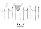
- FIG. 1Adepicts ribs of a prior art Alpha device.
- One ridgewas measured with an average width of about 0.024 inches and a depth of about 0.029 inches. The grooves tend to be somewhat small.
- One groovewas measured with an average width of about 0.034 inches.
- FIG. 1Ashows an area 1 ′ between ribs 2 ′ of a prior art Alpha prosthesis pump. This area was measured as 0.0012 square inches. There is very little area between the ribs 2 ′. This small area is not optimal for affording tissue to extrude between the ribs when the patients squeezes tissue to compress the pump bulb
- the outer surfaces of the ridges of the Alpha I prosthesistend to be rounded, with a large radius at the top.
- One radiuswas meausured at 0.012 inches. This is also believed to be a problem as the rounded tips do not afford optimal tissue purchase and can result in tissue sliding off the tip of the ridge.
- the Mark II® Inflatable Penile Prosthesiswas sold in the United States more than a year prior to the filing date of the present application by Mentor of Santa Barbara, Calif.
- This deviceincluded a pump assembly including a resipump and a release ring.
- the Mark II prosthesishas a single squeeze pump.
- the size of the pumplimits the pressure that can be transmitted to the cylinders and therefore limits the stiffness of the cylinder.
- the Mark II cylinderis believed to afford a much less stiff cylinder than the Alpha I cylinder.
- the release ring of the Mark IIincludes a plurality of ribs. Again, these ribs are rounded and slippery.
- the present inventionincludes an improved protrusion and groove system for an implantable pump.
- the protrusion and groove systemaffords space for tissue to extrude into and surfaces to block movement of the implant relative to tissue in three mutually perpendicular directions.
- the protrusionsare discontinuous and have edges that block movement in a direction substantially parallel to a longitudinal axis of the grooves.
- the protrusionshave less rounded tips than prior art ribs to afford greater tissue purchase and a firmer grasp of the implantable pump.
- the present inventioncomprises a pump assembly for an implantable prosthesis.
- the pump assemblycomprises a housing including a valve assembly, and a pump bulb that is squeezable through tissue.
- the pump bulbhas a plurality of discrete, discontinuous, spaced apart protrusions.
- the protrusionsare sized, shaped and arranged to resist relative movement between tissue and the implantable prosthesis when the pump bulb is squeezed.
- the protrusionscomprise shaped structures selected from the group consisting of oval, linear, elliptical, circular, polygonal, triangular and combinations thereof.
- the pump assemblycomprises a housing including a valve assembly, and a pump bulb having a plurality of protrusions with a longitudinal axes.
- the protrusionsare arranged to be spaced apart by a plurality of grooves with longitudinal axes.
- the protrusionshave ends that separate the protrusions from each other.
- the endspreferably form channels having longitudinal axes extending at angles relative to the longitudinal axes of the grooves. In one embodiment, the angles are approximately ninety degrees.
- the protrusionshave tip portions and the distance between tip portions of adjacent protrusions is preferably greater than 0.05 inches.
- the tip portionshave rounds and the rounds preferably have a radius of less than about 0.012 inches. More preferably, the rounds have a radius of less than about 0.006 inches.
- the ends of the protrusionsform a channel with a longitudinal axis that is configured at an angle relative to the longitudinal axes of the protrusions. In one embodiment, the angle is approximately ninety degrees. In another, it is approximately, forty-five degrees.
- the present inventioncomprises a pump assembly for a prosthesis that is implantable in tissue.
- the pump assemblycomprises a housing including a valve assembly, a pump bulb having a plurality of protrusions spaced apart by grooves, wherein the protrusions and grooves have structure capable of blocking movement of the prosthesis relative to the tissue in three dimensions.
- the present inventioncomprises an implantable penile prosthesis.
- the devicecomprises a reservoir for storing fluid; a pump assembly in fluid communication with the reservoir; and a pair of cylinders in fluid communication with the pump assembly.
- the pump assemblycomprises a housing including a valve assembly.
- the housingis adapted to be deformed to operate the valve assembly.
- the housinghas at least three protrusions, and a pump bulb.
- the present inventioncomprises an implantable penile prosthesis comprising a reservoir for storing fluid; a pump assembly in fluid communication with the reservoir; and a pair of cylinders in fluid communication with the pump assembly.
- the pump assemblycomprises a pump bulb; a bar shaped housing including a valve assembly.
- the housingis adapted to be deformed to operate the valve assembly.
- the housinghas end portions and side portions. Each end portion has at least one protrusion.
- the side portionshave a side bar.
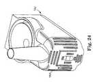
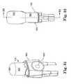
- FIG. 1is a perspective view of an embodiment of pump assembly according to one aspect of the present invention
- FIG. 1Ais a schematic depiction of a portion of a prior art pump for a penile prosthesis
- FIG. 2is a side view of the pump assembly of FIG. 1 ;
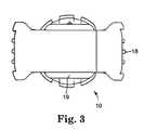
- FIG. 3is a bottom view of the pump assembly of FIG. 1 ;
- FIG. 4is a right side view of the pump assembly of FIG. 1 ;
- FIG. 4Ais an end view of a component according to a preferred embodiment of the present invention.
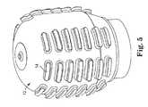
- FIG. 5is a perspective view of a pump bulb component of the pump assembly of FIG. 1 ;
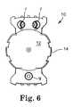
- FIG. 6is a top view of the pump assembly of FIG. 1 ;
- FIG. 7is a sectional view of one embodiment of valve assembly for use with the present invention, taken approximately along lines A—A of FIG. 6 ;
- FIG. 8is a sectional view of another embodiment of valve assembly for use with the present invention, which could also be taken approximately along lines A—A of FIG. 6
- FIG. 9is a perspective view of another component of a pump assembly according to another aspect of the present invention.
- FIG. 10is a perspective view of another component of a pump assembly according to another aspect of the present invention.
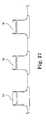
- FIG. 11is an enlarged view of some of the protrusions shown in FIG. 2 ;
- FIG. 12is a front view of a pump bulb component according to another aspect of the present invention.
- FIG. 13is a side view of the component of FIG. 12 ;
- FIG. 14is a perspective view of a pump bulb component according to another aspect of the present invention.
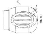
- FIG. 15is a front view of the component of FIG. 14 ;
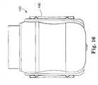
- FIG. 16is a side view of the component of FIG. 14 ;
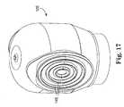
- FIG. 17is a perspective view of a pump bulb component according to another aspect of the present invention.
- FIG. 18is a perspective view of a pump bulb component according to another aspect of the present invention.
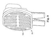
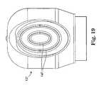
- FIG. 19is a front view of the component of FIG. 18 ;
- FIG. 20is a side view of the component of FIG. 18 ;
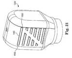
- FIG. 21is a perspective view of a pump bulb component according to another aspect of the present invention.
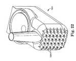
- FIG. 22is a perspective view of a pump housing component according to another aspect of the present invention.
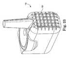
- FIG. 23is a perspective view of a pump housing component according to another aspect of the present invention.
- FIG. 24is a perspective view of a pump housing component according to another aspect of the present invention.
- FIG. 25is a sketch of a cross-sectional view of protrusions according to an embodiment of the present invention.
- FIG. 25Ais a side view of a pump bulb according to a preferred embodiment of the present invention.
- FIG. 25Bis a sectional view of the pump bulb of FIG. 25A ;
- FIG. 26is a perspective view of a pump housing component according to another aspect of the present invention.
- FIG. 27is an side view of the protrusions of FIG. 11 ;
- FIG. 28is a perspective view of another aspect of pump assembly according to the present invention.
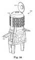
- FIG. 29is a perspective view of another aspect of pump assembly according to the present invention.
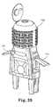
- FIG. 30is a perspective view of another aspect of pump assembly according to the present invention.
- FIG. 31is a perspective view of another aspect of pump assembly according to another aspect of the present invention.
- FIG. 32is a side view of FIG. 31 ;
- FIG. 33is a sectional view taken approximately along lines 33 — 33 of FIG. 32 , which sectional view shows the pump assembly in an auto deflate/lock-out position;
- FIG. 34is a sectional view taken approximately along lines 33 — 33 of FIG. 32 , which sectional view shows the pump assembly in an active suction/pumping position;
- FIG. 35is a sectional view of another embodiment of pump assembly according to the present invention, which view shows a sphere in a deflate/lockout position with dashed lines and in an active (pumping) position in solid lines;
- FIG. 36is a perspective view of an alternative embodiment of housing with protrusions according to the present invention.
- FIG. 37is a side view of the housing of FIG. 36 ;
- FIG. 38is a perspective view of the housing of FIG. 36 ;
- FIG. 39is another perspective view of the housing of FIG. 36 ;
- FIG. 40is another perspective view of the housing of FIG. 36 .
- the pump assembly 10includes a pump bulb 12 having a plurality of protrusions 14 with a longitudinal axes L (FIG. 2 ).
- the protrusions 12are spaced apart by a plurality of grooves G with longitudinal axes A.
- the protrusions 14have ends 15 that separate the protrusions 14 from each other.
- the pump assembly 10is adapted to be in fluid communication with a reservoir via tube 9 .
- the pump assembly 10is adapted to be in fluid communication with implantable inflatable members via tubes 7 .
- the protrusion ends 15form channels C having longitudinal axes A′ extending at angles relative to the longitudinal axes A of the grooves G.
- the angleis approximately ninety degrees, but other angles are also contemplated herein.
- the ends 15face each other across channels C.
- the protrusions 14facilitate traction on the pump bulb 12 and resist movement of the bulb 12 relative to tissue in multiple directions as force is applied to compress bulb 12 .
- the protrusions 15resist slipping latitudinally as well as longitudinally.
- the protrusions, grooves, and channelsare sized shaped and arranged to afford efficient interaction with tissue.
- the protrusionshelp direct the application of force to desired areas, afford tactile location and fixation within tissue (e.g. of the scrotum).
- tissuee.g. of the scrotum.
- a variety of factorsaffect protrusion performance, including the material comprising the protrusions, their width, their height, and shape including cross sectional shape.
- the protrusionsshould be robust enough to hold the pump assembly substantially stationary relative to tissue during operation of an implant associated with the pump assembly 10 .
- the protrusions 14should be sufficiently flexible to avoid unduly irritating tissue.
- the protrusionmay comprise shaped structures selected from the group consisting of oval, linear, elliptical, circular, polygonal, triangular and combinations thereof.
- the pump bulb 12is preferably is squeezable through tissue (e.g. scrotal tissue or other tissue).
- tissuee.g. scrotal tissue or other tissue.
- the protrusions 14are sized, shaped and arranged to resist relative movement between tissue and the implantable prosthesis when the pump bulb 12 is squeezed.
- the protrusions 14 and grooves Ghave structure capable of blocking movement of the implantable prosthesis relative to tissue in three mutually perpendicular directions.
- protrusion 14is shown an embodiment of protrusion 14 according to a preferred aspect of the present invention.
- the protrusionsare constructed from 50-55 durometer silicone elastomer, available from Nusil of California. Any suitable medical grade materials may be utilized, such as, but no limited to silicone rubber (e.g. polydimethyl siloxane), thermoset materials, Thermoset or thermoplastic urethanes, C-flex, santoprene thermoplastics and the like.
- FIG. 25there is shown another sketch of a protrusion and groove assembly according to the present invention.
- the protrusions 14 ′have a width W at the tip of about 0.04 inches, a height H of about 0.04 inches, and the tip edges have a radius R′ of about 0.005 inches.
- the groovehas a length L′′ between tips of about 0.065 inches with a valley radius V of about 0.015 inches.
- FIGS. 25A and 25Bare engineering drawings of a preferred embodiment of the protrusions, with preferred dimensions shown in inches.
- the radius R′ of the tips of the protrusions 14is preferably small (e.g. less than 0.012 inches), more preferably, they are less than about 0.006 inches.
- the radiusshould not be so small as to damage or unduly irritate tissue.
- the pump assemblyalso includes a housing 16 that includes a valve assembly. In general, some portion of the housing 16 is deflectable or deformed to actuate the valve assembly.
- the valve assemblymay comprise any suitable valve assembly including, but not limited to, those valve assemblies disclosed in U.S. Provisional Application Nos. 60/453,684, filed Mar. 10, 2003, 60/508,123 filed Oct. 2, 2003; 60/507,973, filed Oct. 2, 2003, and 60/507,975, filed Oct. 2, 2003; published U.S. patent application Ser. Nos. 2002-91302-A1, 2002-82709-A1; 2002-82708-A1; 2002-82473-A1; and 2002-82471-A1; and U.S. Pat. Nos. 6,443,887 and 6,533,719.
- Various components useable in conjunction with the present inventionare also disclosed in the previously mentioned applications and U.S. Provisional Application Nos. 60/507,972 and 60/507,974 which were filed Oct. 2, 2003.
- the valve assemblymay also comprise the valve assemblies associated with the Mark II Inflatable Penile Prosthesis and the Alpha I Inflatable Penile Prosthesis, each available from Mentor Corp. Examples of valve assemblies are also disclosed in U.S. Pat. Nos. 4,566,466 and 4,537,183.
- valve assembly 20includes a spring biased poppet or ball valve 22 , a spring biased suction poppet 24 and fluid passageways 26 for communicating with a pump bulb 12 A, inflatables 28 (e.g. penile prosthesis cylinders) and a fluid reservoir 29 .
- inflatables 28e.g. penile prosthesis cylinders
- FIG. 8shows another embodiment of valve assembly 20 B suitable for use with the present invention.
- This example of valve assemblyincludes a spring biased poppet or ball valve 22 B, a fluid bypass chamber 21 , lip seal 23 , ball valve 27 , a spring biased suction poppet 24 B and fluid passageways 26 B for communicating with pump bulb 12 B, inflatables 28 B (e.g. penile prosthesis cylinders) and a fluid reservoir 29 B.
- inflatables 28 Be.g. penile prosthesis cylinders
- the housing 16also includes protrusions 18 .
- the protrusions 18should afford stabilization of the implant within tissue (e.g. the scrotum), afford tactile feedback to the patient and assist the patient in actuating the valve assembly.
- the housing 16is preferably bar shaped as shown in FIGS. 1-6 , with end portions and side portions. Preferably, the end portions have at least three protrusions 18 total, preferably more.
- FIG. 4Ais an engineering drawing of a preferred embodiment showing preferred dimensions for protrusions according to one embodiment of the present invention.
- the protrusions 18have a preferred height of about 0.040 inches.
- the housing 16preferably includes two elongate sidebars or stabilizing fins 19 on the side portions.
- the fins 19are sized, shaped and positioned to assist the patient in accessing and/or holding onto the pump.
- the pumpmay tend to elevate relative to the patient's scrotum. In such cases, a patient may reach up to grab the pump and pull it down to access either the inflation or deflation area.
- Some patientslack manual dexterity. Such patients use two hands to inflate and/or deflate—one hand to hold the pump in place and one hand to either inflate or deflate.
- the pumpis constructed of a silicone elastomer (or other similar materials) and bathed in body fluids, the pump can be very slippery and hard to grasp.
- the fins 19enhance the patient's grip on the side of the pump to pull it down and/or to hold onto the pump.
- the fins 19operate in a manner similar to the way the protrusions on the bulb and deflation area operate to enhance the patient's grip for inflation and deflation.
- the fins 19have a width of about 0.07 inches, a height of about 0.08 inches and a length of about 0.55 inches.
- FIGS. 9 and 10show another embodiment of portions of a pump assembly housing 50 that is similar to the housing 16 in FIG. 4 , except that protrusions 18 A are straight instead of arcuate shaped.
- FIGS. 12 and 13show another embodiment of component or portion of pump bulb 12 C according to the present invention.
- the protrusions 14 Care oval shaped rather than linear.
- the protrusions 14 C and intervening grooves/valleysare believed to resist slippage in three mutually perpendicular directions.
- FIGS. 14 through 16show another embodiment of component or portion of pump bulb 12 D according to the present invention.
- the protrusions 14 Dare a combination of straight and arcuate shaped structures.
- the straight protrusionsafford a relative sharp configuration at its top.
- FIG. 17shows a pump bulb 12 E with circular protrusions 14 E.
- the protrusions and intervening grooves/valleysare believed to resist slippage in three mutually perpendicular directions.
- FIGS. 18 through 20show a pump bulb 12 F with generally elliptically shaped protrusions 14 F.
- FIG. 21shows a pump bulb 12 G with substantially linearly extending protrusions 14 G with ends 15 G.
- FIG. 22shows a portion of a pump housing 16 H and a plurality of protrusions 18 H.
- the tips of the protrusions 18 Hare relatively sharp but so sharp that they unduly irritate or damage tissue.
- FIG. 23shows a portion of a pump housing 16 I and a plurality of protrusions 18 I.
- FIG. 24shows a portion of a pump housing 16 J and a plurality of protrusions 18 J.
- FIG. 26shows a portion of a pump housing 16 L and a plurality of protrusions 18 L.
- the protrusionscomprise a maze shaped protrusion 18 L and a plurality of partial sphere shaped protrusions 18 L′.
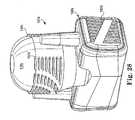
- FIG. 28shows another embodiment of pump assembly 10 N according to the present invention.
- the pump assembly 10 Nincludes a pump bulb 12 N with protrusions 14 N having ends 15 N, pump housing 16 N and protrusions 18 N.
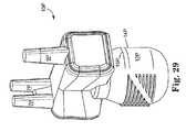
- FIG. 29shows a pump assembly 10 P includes a pump bulb 12 P with protrusions 14 P having ends 15 P, pump housing 16 P and fluid connectors 7 P and 9 P.
- FIG. 30shows a pump assembly 10 Q that includes a pump bulb 12 Q with protrusions 14 Q having ends 15 Q, pump housing 16 Q and fluid connectors 7 Q and 9 Q.
- the axis A of grooves G′ formed by the protrusions 14 Qis at a non-normal angle relative to the axis A′ of channels C′.
- FIGS. 31 through 34there is shown another embodiment of pump assembly 10 X according to the present invention.
- the pump assemblyincludes fluid communication members 7 X and 9 X, pump bulb 12 X, housing 16 X, protrusions 18 X and internal valve sphere 99 .
- FIG. 34is a cross section view of the pump assembly in the active suction/pumping position.
- FIG. 33is a cross sectional view of the pump assembly in the auto deflate/lock-out position.
- a well defined concave protrusion 18 Xis shown comprising a raised palpable button for locating the auto deflate area.
- the sphere 99blocks the deflate fluid channel and prevents pressurized fluid in the cylinders (see line 9 X) returning to the reservoir (see line 7 X).
- pressurized fluid in the cylindersis allowed to return to the reservoir unassisted by the patient holding the pump to obtain maximum flaccidity, the patient need only bend or squeeze the cylinders without manipulating the pump.
- a square deflation featuremay be utilized.
- FIG. 35is a sectional view of another embodiment.
- the sphere 99 Ais shown in a deflate/lockout position with dashed lines and an active (pumping) position with solid lanes.
- housing 100includes protrusions 112 .
- the housing 100is particularly suitable for incorporating valve assemblies similar to those described with reference to FIGS. 31-35 .
- the housing 100may advantageously be molded as a one-piece (e.g. integral or monolithic) part.
- the housing 100preferably includes live hinges 111 that may be incorporated into the design/mold. Medical grade adhesives may be used to hold the live hinges in a closed or sealed position.
- artificial sphinctersutilize fluid pressure to maintain a body cavity or natural passageway in a closed or sealed state. When actuated, fluid pressure is released from the sphincter, causing the bodies' passageway to open.
- the present inventionmay be utilized with an artificial sphincter as well.
Landscapes
- Health & Medical Sciences (AREA)
- Reproductive Health (AREA)
- Cardiology (AREA)
- Oral & Maxillofacial Surgery (AREA)
- Transplantation (AREA)
- Engineering & Computer Science (AREA)
- Biomedical Technology (AREA)
- Heart & Thoracic Surgery (AREA)
- Vascular Medicine (AREA)
- Life Sciences & Earth Sciences (AREA)
- Animal Behavior & Ethology (AREA)
- General Health & Medical Sciences (AREA)
- Public Health (AREA)
- Veterinary Medicine (AREA)
- Prostheses (AREA)
Abstract
Description
Claims (6)
Priority Applications (3)
| Application Number | Priority Date | Filing Date | Title |
|---|---|---|---|
| US10/725,711US6991601B2 (en) | 2002-12-02 | 2003-12-02 | Implantable pump |
| US11/186,225US7874978B2 (en) | 2002-12-02 | 2005-07-21 | Implantable pump |
| US12/967,776US8062209B2 (en) | 2002-12-02 | 2010-12-14 | Implantable pump |
Applications Claiming Priority (2)
| Application Number | Priority Date | Filing Date | Title |
|---|---|---|---|
| US43020002P | 2002-12-02 | 2002-12-02 | |
| US10/725,711US6991601B2 (en) | 2002-12-02 | 2003-12-02 | Implantable pump |
Related Child Applications (1)
| Application Number | Title | Priority Date | Filing Date |
|---|---|---|---|
| US11/186,225DivisionUS7874978B2 (en) | 2002-12-02 | 2005-07-21 | Implantable pump |
Publications (2)
| Publication Number | Publication Date |
|---|---|
| US20040138523A1 US20040138523A1 (en) | 2004-07-15 |
| US6991601B2true US6991601B2 (en) | 2006-01-31 |
Family
ID=32717682
Family Applications (3)
| Application Number | Title | Priority Date | Filing Date |
|---|---|---|---|
| US10/725,711Expired - LifetimeUS6991601B2 (en) | 2002-12-02 | 2003-12-02 | Implantable pump |
| US11/186,225Active2026-11-11US7874978B2 (en) | 2002-12-02 | 2005-07-21 | Implantable pump |
| US12/967,776Expired - LifetimeUS8062209B2 (en) | 2002-12-02 | 2010-12-14 | Implantable pump |
Family Applications After (2)
| Application Number | Title | Priority Date | Filing Date |
|---|---|---|---|
| US11/186,225Active2026-11-11US7874978B2 (en) | 2002-12-02 | 2005-07-21 | Implantable pump |
| US12/967,776Expired - LifetimeUS8062209B2 (en) | 2002-12-02 | 2010-12-14 | Implantable pump |
Country Status (1)
| Country | Link |
|---|---|
| US (3) | US6991601B2 (en) |
Cited By (31)
| Publication number | Priority date | Publication date | Assignee | Title |
|---|---|---|---|---|
| US20050250982A1 (en)* | 2002-12-02 | 2005-11-10 | Kuyava Charles C | Implantable pump |
| US20070142700A1 (en)* | 2005-12-19 | 2007-06-21 | Fogarty Terence M | Pump with one-touch release |
| US20090084447A1 (en)* | 2000-12-27 | 2009-04-02 | Ams Research Corporation | Diaphragm Based Spontaneous Inflation Inhibitor in a Pump for an Inflatable Prosthesis |
| US20090105530A1 (en)* | 2007-10-23 | 2009-04-23 | Ams Research Corporation | Corrugated Inflatable Penile Prosthesis Cylinder |
| US20090132043A1 (en)* | 2007-11-15 | 2009-05-21 | George Stephanie A | Prosthesis with Bladder that Adjusts Girth |
| US20090287042A1 (en)* | 2000-12-27 | 2009-11-19 | Ams Research Corporation | Penile Pump with Side Release Mechanism |
| US20100160722A1 (en)* | 2008-12-23 | 2010-06-24 | Ams Research Corporation | Penile prosthesis implantation device |
| US20110118540A1 (en)* | 2009-11-16 | 2011-05-19 | Coloplast A/S | Penile prosthetic with anti-autoinflation mechanism |
| US7946975B2 (en) | 2005-04-08 | 2011-05-24 | Ams Research Corporation | Fluid reservoir for penile implant devices |
| US20110190577A1 (en)* | 2010-02-03 | 2011-08-04 | Coloplast A/S | Inflatable penile implant |
| US20110190576A1 (en)* | 2010-02-04 | 2011-08-04 | Coloplast A/S | Inflatable penile implant |
| US20110201880A1 (en)* | 2010-02-12 | 2011-08-18 | Fogarty Terence M | Inflatable penile prosthesis with spool valve |
| US8109870B2 (en) | 2006-11-10 | 2012-02-07 | Ams Research Corporation | Inflatable penile prosthesis bypass valve noise reduction |
| US8123674B2 (en) | 2007-11-12 | 2012-02-28 | Ams Research Corporation | Corrugated expansion-constraining sleeve for an inflatable penile prosthesis cylinder |
| US8257246B1 (en) | 2011-04-19 | 2012-09-04 | Coloplast A/S | Penile prosthetic system and pump having inlet valve with high velocity closure mechanism |
| US20130041213A1 (en)* | 2011-08-08 | 2013-02-14 | Coloplast A/S | Penile prosthetic deflation assembly having a palpatable activation surface |
| US8684910B2 (en) | 2011-08-08 | 2014-04-01 | Coloplast A/S | Method of implanting a penile prosthetic deflation assembly having a palpatable activation surface |
| US8911350B2 (en) | 2007-10-23 | 2014-12-16 | Ams Research Corporation | Malleable prosthesis with enhanced concealability |
| US9084678B2 (en) | 2012-01-20 | 2015-07-21 | Ams Research Corporation | Automated implantable penile prosthesis pump system |
| US9089426B2 (en) | 2012-03-21 | 2015-07-28 | Ams Research Corporation | Automated implantable penile prosthesis pump system |
| US9308088B2 (en) | 2011-08-08 | 2016-04-12 | Coloplast A/S | Artificial urinary sphincter system deflation assembly |
| US9451982B1 (en) | 2015-06-06 | 2016-09-27 | Coloplast A/S | System for implanting a penile prosthetic into a penis includes a delivery cap coupled to a tow suture |
| US9474610B2 (en) | 2010-12-21 | 2016-10-25 | Boston Scientific Scimed, Inc. | Adjustable length rear tip extender for penile prosthesis |
| US9554937B2 (en) | 2014-06-16 | 2017-01-31 | Coloplast A/S | Penile prosthetic pump having an inlet valve with a lockout flange |
| US9649217B2 (en) | 2014-07-08 | 2017-05-16 | Coloplast A/S | Implantable penile prosthetic lockout valve assembly |
| US9724182B2 (en) | 2014-10-17 | 2017-08-08 | Coloplast A/S | Connector cuff |
| US9907653B2 (en) | 2015-07-27 | 2018-03-06 | Coloplast A/S | Pump bulb for an implantable penile prosthetic |
| US9987136B2 (en) | 2016-09-09 | 2018-06-05 | Coloplast A/S | Penile prosthetic pump with an inflation assembly including a rotary valve |
| US10952855B2 (en) | 2016-03-24 | 2021-03-23 | Boston Scientific Scimed, Inc. | Inflatable penile prosthesis with reversible flow pump assembly |
| US11311382B2 (en) | 2018-11-27 | 2022-04-26 | Boston Scientific Scimed, Inc. | Pump assembly having a push valve for a penile prosthesis |
| US12083016B2 (en) | 2020-10-15 | 2024-09-10 | Boston Scientific Scimed, Inc. | Pump assembly for a penile prosthesis |
Families Citing this family (11)
| Publication number | Priority date | Publication date | Assignee | Title |
|---|---|---|---|---|
| US6808490B1 (en)* | 2003-04-25 | 2004-10-26 | Ams Research Corporation | Penile prosthesis with improved tubing junction |
| FR2922754B1 (en)* | 2007-10-24 | 2010-12-31 | Zephyr Surgical Implants | SURGICAL IMPLANT AND IN PARTICULAR ARTIFICIAL SPHINCTER WITH REGULATED PRESSURE. |
| DK200900718A (en) | 2009-06-08 | 2010-12-09 | Coloplast As | Anatomical augmentation device |
| EP2536350A4 (en)* | 2010-02-18 | 2015-12-23 | Univ Texas | IMPLANTABLE URBAN PROSTHESIS HAVING AN INFLATABLE ELEMENT |
| US8939889B1 (en) | 2013-08-22 | 2015-01-27 | Coloplast A/S | Pump bulb for an implantable penile prosthetic |
| EP3123981B1 (en)* | 2015-07-27 | 2021-10-20 | Coloplast A/S | Pump bulb for an implantable penile prosthetic |
| US10980637B2 (en)* | 2017-05-05 | 2021-04-20 | Boston Scientific Scimed, Inc. | Inflatable penile prosthesis with pump bulb |
| US11337814B2 (en)* | 2018-11-16 | 2022-05-24 | Boston Scientific Scimed, Inc. | Pump assembly for a penile prosthesis having an outer protective casing |
| US11234824B2 (en)* | 2019-05-08 | 2022-02-01 | Boston Scientific Scimed, Inc. | Pump bulb with control features |
| US11547566B2 (en) | 2019-08-06 | 2023-01-10 | Boston Scientific Scimed, Inc. | Inflatable penile prosthesis with guides in valve of pump assembly |
| US11890250B2 (en) | 2020-01-29 | 2024-02-06 | Boston Scientific Scimed, Inc. | Inflatable penile prosthesis with channels in valve of guide assembly |
Citations (101)
| Publication number | Priority date | Publication date | Assignee | Title |
|---|---|---|---|---|
| US988120A (en) | 1910-02-15 | 1911-03-28 | John B Lott | Dilator. |
| US1863057A (en) | 1930-03-03 | 1932-06-14 | George A Innes | Surgical drain |
| US3312215A (en) | 1963-08-02 | 1967-04-04 | Max N Silber | Uterocervical cannula |
| US3344791A (en) | 1965-02-12 | 1967-10-03 | John W Foderick | Bulbous urinary catheter with axial extension means |
| US3397699A (en) | 1966-05-05 | 1968-08-20 | Gerald C. Kohl | Retaining catheter having resiliently biased wing flanges |
| US3503400A (en) | 1967-07-12 | 1970-03-31 | Sven M Osthagen | Urethral valve |
| US3642004A (en) | 1970-01-05 | 1972-02-15 | Life Support Equipment Corp | Urethral valve |
| US3731670A (en) | 1971-05-03 | 1973-05-08 | David Roy Pressman | Corporeal fluid control using bistable magnetic duct valve |
| US3797478A (en) | 1972-07-11 | 1974-03-19 | M Walsh | Multi-functional valve for use in the urethra |
| US3812841A (en) | 1972-08-21 | 1974-05-28 | L Isaacson | Urethra magnetic valve structure |
| US3954102A (en) | 1974-07-19 | 1976-05-04 | American Medical Systems, Inc. | Penile erection system and methods of implanting and using same |
| DE2537506A1 (en) | 1975-08-22 | 1977-03-03 | Hennig Gerhard | Bladder outlet valve for incontinent people - has magnet cone embedded in magnet ring seat with powerful external opening magnet |
| US4222377A (en) | 1977-06-27 | 1980-09-16 | American Medical Systems, Inc. | Pressure regulated artificial sphincter systems |
| US4224934A (en) | 1979-04-11 | 1980-09-30 | American Medical Systems, Inc. | Medical prosthetic pull valve and system for using same |
| US4235227A (en) | 1978-11-08 | 1980-11-25 | Hideo Yamanaka | Artificial corpus cavernosum device |
| US4244370A (en) | 1978-11-20 | 1981-01-13 | American Medical Systems, Inc. | Tool for positioning implantable medical prosthetic device _and method of using same |
| US4267829A (en) | 1979-04-11 | 1981-05-19 | American Medical Systems, Inc. | Penile prosthesis |
| US4344434A (en) | 1981-06-01 | 1982-08-17 | Santa Barbara Medical Foundation Clinic | Ileostomy appliance and method for implanting the same |
| US4392562A (en) | 1981-06-19 | 1983-07-12 | American Medical Systems, Inc. | Limited bend malleable penile prosthesis |
| US4407278A (en) | 1981-05-15 | 1983-10-04 | American Medical Systems, Inc. | Penile prosthesis with improved fluid control |
| US4412530A (en) | 1981-09-21 | 1983-11-01 | American Medical Systems, Inc. | Dual-mode valve pressure regulating system |
| US4453536A (en) | 1980-11-03 | 1984-06-12 | Abild Robert N | Body channel occluder |
| US4489732A (en) | 1982-09-20 | 1984-12-25 | Hasson Harrith M | Gynecological instrument |
| US4537183A (en)* | 1983-04-08 | 1985-08-27 | Mentor Corporation | Connector device for connecting elastic tubing of an implantable device |
| US4553959A (en) | 1982-01-27 | 1985-11-19 | The Victoria University Of Manchester | Urethral catheter |
| US4559931A (en) | 1983-03-21 | 1985-12-24 | Fischell Robert | Manually actuated fully implantable penile erection device |
| US4566466A (en)* | 1984-04-16 | 1986-01-28 | Ripple Dale B | Surgical instrument |
| US4566446A (en) | 1983-04-08 | 1986-01-28 | Mentor Corporation | Penile prosthesis device |
| US4571241A (en) | 1983-12-16 | 1986-02-18 | Christopher T Graham | Urinary catheter with collapsible urethral tube |
| US4572168A (en) | 1983-12-20 | 1986-02-25 | Fischell Robert | Fully implantable vapor pressure actuated penile erection device and method |
| US4590927A (en) | 1985-02-25 | 1986-05-27 | American Medical Systems, Inc. | Unitary, inflatable penile prosthesis system |
| US4594998A (en) | 1983-09-16 | 1986-06-17 | American Medical Systems, Inc. | Penile prosthesis of improved malleable construction |
| US4596242A (en) | 1983-08-26 | 1986-06-24 | Fischell Robert | Method and apparatus for achieving penile erection in a human male |
| US4628912A (en) | 1984-08-20 | 1986-12-16 | Fischell Robert | Adjustable root and tip extenders for the stiffener cylinder of a penile erection device |
| US4632435A (en) | 1984-12-27 | 1986-12-30 | American Medical Systems, Inc. | Tubing connector system |
| US4651721A (en) | 1985-04-10 | 1987-03-24 | American Medical Systems, Inc. | Penile prosthesis system |
| US4653485A (en) | 1984-07-23 | 1987-03-31 | Fishell Robert E | Penile erection device stiffener cylinder and implantation method |
| US4669456A (en) | 1983-05-04 | 1987-06-02 | Mentor Corporation | Positionable penile prosthesis |
| US4671261A (en) | 1986-01-24 | 1987-06-09 | Fischell Robert | Penile erection device with valving in the penile cylinder |
| US4682583A (en) | 1984-04-13 | 1987-07-28 | Burton John H | Inflatable artificial sphincter |
| US4710169A (en) | 1983-12-16 | 1987-12-01 | Christopher T Graham | Urinary catheter with collapsible urethral tube |
| US4718410A (en) | 1978-08-02 | 1988-01-12 | Hakky Said I | Surgical implants |
| US4730607A (en) | 1984-08-20 | 1988-03-15 | Fischell Robert | Stiffener cylinder for an inflatable penile erection device |
| US4782826A (en) | 1987-05-21 | 1988-11-08 | Mentor Corporation | Penile prosthesis |
| US4807608A (en) | 1987-07-22 | 1989-02-28 | American Medical Systems | Mechanical penile prosthesis |
| US4850963A (en) | 1986-06-11 | 1989-07-25 | Utah Bioresearch, Inc. | Apparatus and methods for achieving urinary continence |
| US4890866A (en) | 1989-03-14 | 1990-01-02 | Mentor Corporation | Tubing connector |
| US4895139A (en) | 1988-08-29 | 1990-01-23 | American Medical Systems, Inc. | Inflatable penile prosthesis with bend release valve |
| US4932938A (en) | 1989-05-05 | 1990-06-12 | Medical Engineering Corporation | Urethral indwelling catheter with incontinence control |
| US4941461A (en) | 1989-09-05 | 1990-07-17 | Fischell Robert | Electrically actuated inflatable penile erection device |
| US4944732A (en) | 1988-08-15 | 1990-07-31 | Sandoz Nutrition Corporation | Gastrostomy feeding port |
| US4958630A (en) | 1989-10-06 | 1990-09-25 | Advanced Surgical Intervention, Inc. | Method and apparatus for treating impotence |
| US4960425A (en) | 1987-05-27 | 1990-10-02 | Mentor Corporation | Textured surface frosthesis implants |
| US4968294A (en) | 1989-02-09 | 1990-11-06 | Salama Fouad A | Urinary control valve and method of using same |
| EP0397500A2 (en) | 1989-05-10 | 1990-11-14 | United States Surgical Corporation | Synthetic semiabsorbable yarn, fabric and tubular prosthesis |
| US5010882A (en) | 1989-11-13 | 1991-04-30 | American Medical Systems, Inc. | Implantable penile prosthesis |
| US5022942A (en) | 1987-05-27 | 1991-06-11 | Mentor Corporation | Method of making textured surface prosthesis implants |
| US5030199A (en) | 1989-12-11 | 1991-07-09 | Medical Engineering Corporation | Female incontinence control device with magnetically operable valve and method |
| US5034009A (en) | 1987-11-03 | 1991-07-23 | Mouchel Jack A P | Instrument for locating the proximal end of the urethra |
| US5033893A (en) | 1989-05-12 | 1991-07-23 | Raison Pure S.A. | Case with filiform members and winding drum |
| US5041092A (en) | 1989-08-29 | 1991-08-20 | Medical Engineering Corporation | Urethral indwelling catheter with magnetically controlled drainage valve and method |
| US5048511A (en) | 1989-10-06 | 1991-09-17 | Advanced Surgical Intervention, Inc. | Method and apparatus for treating impotence |
| US5048510A (en) | 1988-08-29 | 1991-09-17 | American Medical Systems, Inc. | Inflatable penile prosthesis with satellite reservoir |
| US5062417A (en) | 1990-10-10 | 1991-11-05 | Mentor Corporation | Prosthesis with improved pump |
| US5063914A (en) | 1990-05-30 | 1991-11-12 | Mentor Corporation | Penile prosthesis |
| US5067485A (en) | 1990-05-14 | 1991-11-26 | Mentor Corporation | Corpus cavernosum implant device |
| US5074849A (en) | 1990-01-22 | 1991-12-24 | Sachse Hans Ernst | Ureter drainage tube with fixable auxiliary tube |
| US5085650A (en) | 1989-10-20 | 1992-02-04 | Giglio Frank A | Gynecological urethral suppository |
| US5088980A (en) | 1990-05-31 | 1992-02-18 | The United States Of America As Represented By The Department Of Health And Human Services | Intra-urethral valve with integral spring |
| US5090424A (en) | 1990-12-31 | 1992-02-25 | Uromed Corporation | Conformable urethral plug |
| US5112295A (en) | 1990-04-20 | 1992-05-12 | Zinner Norman R | Penile prosthesis and method |
| US5114398A (en) | 1990-02-27 | 1992-05-19 | Medical Engineering Corporation | Female incontinence control device with mechanically operable valve |
| US5131906A (en) | 1988-10-20 | 1992-07-21 | Chen Fusen H | Incontinence device |
| US5141509A (en) | 1991-08-06 | 1992-08-25 | American Medical Systems, Inc. | Penile prosthesis having means for preventing spontaneous inflation |
| US5167611A (en) | 1991-07-22 | 1992-12-01 | Mentor Corporation | Penile implant with lengthening cylinder |
| US5171272A (en) | 1990-09-24 | 1992-12-15 | American Medical Systems, Inc. | Fluid pump for penile prosthesis |
| US5186180A (en) | 1989-08-07 | 1993-02-16 | Bellas Gabriel A S | Intra-vaginal prolapse diagnostic instrument |
| US5250020A (en) | 1991-09-12 | 1993-10-05 | Mentor Corporation | Unitary inflatable penile prosthesis |
| US5263981A (en) | 1992-04-24 | 1993-11-23 | American Medical Systems, Inc. | Implantable penile prosthesis |
| US5295978A (en) | 1990-12-28 | 1994-03-22 | Union Carbide Chemicals & Plastics Technology Corporation | Biocompatible hydrophilic complexes and process for preparation and use |
| US5329834A (en)* | 1993-06-07 | 1994-07-19 | Jason Wong | Multi-angle all-purpose ratchet screwdriver |
| US5344388A (en) | 1991-05-01 | 1994-09-06 | Maxwell G Patrick | Textured surface prosthetic device |
| US5468213A (en) | 1994-09-22 | 1995-11-21 | American Medical Systems, Inc. | Mechanical penile prosthesis |
| US5484450A (en) | 1994-06-20 | 1996-01-16 | Mohamed; Adel W. | Penile prosthesis implant insertion instrument |
| US5512033A (en) | 1994-08-08 | 1996-04-30 | American Medical Systems, Inc. | Malleable penile prosthesis |
| US5645924A (en) | 1994-11-10 | 1997-07-08 | E. I. Du Pont De Nemours And Company | Elastic woven fabric |
| US5658280A (en) | 1995-05-22 | 1997-08-19 | Issa; Muta M. | Resectoscope electrode assembly with simultaneous cutting and coagulation |
| US5702387A (en) | 1995-09-27 | 1997-12-30 | Valleylab Inc | Coated electrosurgical electrode |
| US5736251A (en) | 1993-10-18 | 1998-04-07 | Corvita Corporation | Lubricious silicone surface modification |
| US5804318A (en) | 1995-10-26 | 1998-09-08 | Corvita Corporation | Lubricious hydrogel surface modification |
| US5810764A (en) | 1992-01-07 | 1998-09-22 | Arthrocare Corporation | Resecting loop electrode and method for electrosurgical cutting and ablation |
| US5851176A (en) | 1996-07-29 | 1998-12-22 | Mentor Corporation | Pressure-responsive lockout valve and method of use |
| US5887630A (en) | 1996-10-23 | 1999-03-30 | Asten, Inc. | Papermakers fabric with enhanced cmd support and stacking |
| US5895424A (en) | 1996-11-12 | 1999-04-20 | Mentor Corporation | Prosthesis having an alignment indicator and method of using same |
| US5925069A (en) | 1997-11-07 | 1999-07-20 | Sulzer Intermedics Inc. | Method for preparing a high definition window in a conformally coated medical device |
| US6346492B1 (en) | 1999-05-06 | 2002-02-12 | American Medical Systems, Inc. | Fabric for use in prosthetics |
| US20020082473A1 (en) | 2000-12-27 | 2002-06-27 | American Medical Systems | Pressure based spontaneous inflation inhibitor with penile pump improvements |
| US6443887B1 (en) | 2000-12-27 | 2002-09-03 | American Medical Systems Inc. | Switch based spontaneous inflation inhibitor in a pump for an inflation prosthesis |
| US6533719B2 (en) | 2000-12-27 | 2003-03-18 | Ams Research Corporation | Diaphragm based spontaneous inflation inhibitor in a pump for an inflatable prosthesis |
| US6558315B1 (en) | 2000-03-15 | 2003-05-06 | Ams Research Corporation | Parylene-coated components for inflatable penile prosthesis |
| US6723042B2 (en)* | 2000-12-27 | 2004-04-20 | Ams Research Corporation | Penile pump with side release mechanism |
Family Cites Families (9)
| Publication number | Priority date | Publication date | Assignee | Title |
|---|---|---|---|---|
| US4369771A (en)* | 1981-09-24 | 1983-01-25 | Medical Engineering Corporation | Penile erectile system |
| DE3446516A1 (en)* | 1984-12-20 | 1986-06-26 | Hilti Ag, Schaan | SPREADING DOWEL FOR THIN-WALLED COMPONENTS |
| KR960007043B1 (en)* | 1987-04-30 | 1996-05-27 | 가부시기가이샤 히다찌 세이사꾸쇼 | Air Conditioning Device for Railway Vehicles |
| US5094424A (en)* | 1990-11-23 | 1992-03-10 | Hartway James W | Bicycle seat post shock absorber assembly |
| FR2716996B1 (en)* | 1994-03-07 | 1996-04-05 | Commissariat Energie Atomique | Vertical magnetic head and its production process. |
| US5633719A (en)* | 1994-10-28 | 1997-05-27 | Eastman Kodak Company | Method and apparatus for aligning a lenticular overlay with a lenticular print |
| JP3500551B2 (en)* | 1995-10-12 | 2004-02-23 | 澄子 山本 | Short leg orthosis |
| US6991601B2 (en)* | 2002-12-02 | 2006-01-31 | Ams Research Corporation | Implantable pump |
| US7814978B2 (en)* | 2006-12-14 | 2010-10-19 | Halliburton Energy Services, Inc. | Casing expansion and formation compression for permeability plane orientation |
- 2003
- 2003-12-02USUS10/725,711patent/US6991601B2/ennot_activeExpired - Lifetime
- 2005
- 2005-07-21USUS11/186,225patent/US7874978B2/enactiveActive
- 2010
- 2010-12-14USUS12/967,776patent/US8062209B2/ennot_activeExpired - Lifetime
Patent Citations (106)
| Publication number | Priority date | Publication date | Assignee | Title |
|---|---|---|---|---|
| US988120A (en) | 1910-02-15 | 1911-03-28 | John B Lott | Dilator. |
| US1863057A (en) | 1930-03-03 | 1932-06-14 | George A Innes | Surgical drain |
| US3312215A (en) | 1963-08-02 | 1967-04-04 | Max N Silber | Uterocervical cannula |
| US3344791A (en) | 1965-02-12 | 1967-10-03 | John W Foderick | Bulbous urinary catheter with axial extension means |
| US3397699A (en) | 1966-05-05 | 1968-08-20 | Gerald C. Kohl | Retaining catheter having resiliently biased wing flanges |
| US3503400A (en) | 1967-07-12 | 1970-03-31 | Sven M Osthagen | Urethral valve |
| US3642004A (en) | 1970-01-05 | 1972-02-15 | Life Support Equipment Corp | Urethral valve |
| US3731670A (en) | 1971-05-03 | 1973-05-08 | David Roy Pressman | Corporeal fluid control using bistable magnetic duct valve |
| US3797478A (en) | 1972-07-11 | 1974-03-19 | M Walsh | Multi-functional valve for use in the urethra |
| US3812841A (en) | 1972-08-21 | 1974-05-28 | L Isaacson | Urethra magnetic valve structure |
| US3954102A (en) | 1974-07-19 | 1976-05-04 | American Medical Systems, Inc. | Penile erection system and methods of implanting and using same |
| DE2537506A1 (en) | 1975-08-22 | 1977-03-03 | Hennig Gerhard | Bladder outlet valve for incontinent people - has magnet cone embedded in magnet ring seat with powerful external opening magnet |
| US4222377A (en) | 1977-06-27 | 1980-09-16 | American Medical Systems, Inc. | Pressure regulated artificial sphincter systems |
| US4718410A (en) | 1978-08-02 | 1988-01-12 | Hakky Said I | Surgical implants |
| US4235227A (en) | 1978-11-08 | 1980-11-25 | Hideo Yamanaka | Artificial corpus cavernosum device |
| US4244370A (en) | 1978-11-20 | 1981-01-13 | American Medical Systems, Inc. | Tool for positioning implantable medical prosthetic device _and method of using same |
| US4224934A (en) | 1979-04-11 | 1980-09-30 | American Medical Systems, Inc. | Medical prosthetic pull valve and system for using same |
| US4267829A (en) | 1979-04-11 | 1981-05-19 | American Medical Systems, Inc. | Penile prosthesis |
| US5704895A (en) | 1979-12-28 | 1998-01-06 | American Medical Systems, Inc. | Implantable penile prosthetic cylinder with inclusive fluid reservoir |
| US4383525A (en) | 1979-12-28 | 1983-05-17 | American Medical Systems, Inc. | Implantable penile prosthetic cylinder with inclusive fluid reservoir |
| US4453536A (en) | 1980-11-03 | 1984-06-12 | Abild Robert N | Body channel occluder |
| US4407278A (en) | 1981-05-15 | 1983-10-04 | American Medical Systems, Inc. | Penile prosthesis with improved fluid control |
| US4344434A (en) | 1981-06-01 | 1982-08-17 | Santa Barbara Medical Foundation Clinic | Ileostomy appliance and method for implanting the same |
| US4392562A (en) | 1981-06-19 | 1983-07-12 | American Medical Systems, Inc. | Limited bend malleable penile prosthesis |
| US4412530A (en) | 1981-09-21 | 1983-11-01 | American Medical Systems, Inc. | Dual-mode valve pressure regulating system |
| US4553959A (en) | 1982-01-27 | 1985-11-19 | The Victoria University Of Manchester | Urethral catheter |
| US4489732A (en) | 1982-09-20 | 1984-12-25 | Hasson Harrith M | Gynecological instrument |
| US4559931A (en) | 1983-03-21 | 1985-12-24 | Fischell Robert | Manually actuated fully implantable penile erection device |
| US4537183A (en)* | 1983-04-08 | 1985-08-27 | Mentor Corporation | Connector device for connecting elastic tubing of an implantable device |
| US4566446A (en) | 1983-04-08 | 1986-01-28 | Mentor Corporation | Penile prosthesis device |
| US4669456A (en) | 1983-05-04 | 1987-06-02 | Mentor Corporation | Positionable penile prosthesis |
| US4596242A (en) | 1983-08-26 | 1986-06-24 | Fischell Robert | Method and apparatus for achieving penile erection in a human male |
| US4594998A (en) | 1983-09-16 | 1986-06-17 | American Medical Systems, Inc. | Penile prosthesis of improved malleable construction |
| US4710169A (en) | 1983-12-16 | 1987-12-01 | Christopher T Graham | Urinary catheter with collapsible urethral tube |
| US4571241A (en) | 1983-12-16 | 1986-02-18 | Christopher T Graham | Urinary catheter with collapsible urethral tube |
| US4572168A (en) | 1983-12-20 | 1986-02-25 | Fischell Robert | Fully implantable vapor pressure actuated penile erection device and method |
| US4682583A (en) | 1984-04-13 | 1987-07-28 | Burton John H | Inflatable artificial sphincter |
| US4566466A (en)* | 1984-04-16 | 1986-01-28 | Ripple Dale B | Surgical instrument |
| US4653485A (en) | 1984-07-23 | 1987-03-31 | Fishell Robert E | Penile erection device stiffener cylinder and implantation method |
| US4628912A (en) | 1984-08-20 | 1986-12-16 | Fischell Robert | Adjustable root and tip extenders for the stiffener cylinder of a penile erection device |
| US4730607A (en) | 1984-08-20 | 1988-03-15 | Fischell Robert | Stiffener cylinder for an inflatable penile erection device |
| US4632435A (en) | 1984-12-27 | 1986-12-30 | American Medical Systems, Inc. | Tubing connector system |
| US4590927A (en) | 1985-02-25 | 1986-05-27 | American Medical Systems, Inc. | Unitary, inflatable penile prosthesis system |
| US4651721A (en) | 1985-04-10 | 1987-03-24 | American Medical Systems, Inc. | Penile prosthesis system |
| US4671261A (en) | 1986-01-24 | 1987-06-09 | Fischell Robert | Penile erection device with valving in the penile cylinder |
| US4850963A (en) | 1986-06-11 | 1989-07-25 | Utah Bioresearch, Inc. | Apparatus and methods for achieving urinary continence |
| US4782826A (en) | 1987-05-21 | 1988-11-08 | Mentor Corporation | Penile prosthesis |
| US5022942A (en) | 1987-05-27 | 1991-06-11 | Mentor Corporation | Method of making textured surface prosthesis implants |
| US4960425A (en) | 1987-05-27 | 1990-10-02 | Mentor Corporation | Textured surface frosthesis implants |
| US4807608A (en) | 1987-07-22 | 1989-02-28 | American Medical Systems | Mechanical penile prosthesis |
| US5034009A (en) | 1987-11-03 | 1991-07-23 | Mouchel Jack A P | Instrument for locating the proximal end of the urethra |
| US4944732A (en) | 1988-08-15 | 1990-07-31 | Sandoz Nutrition Corporation | Gastrostomy feeding port |
| US4895139A (en) | 1988-08-29 | 1990-01-23 | American Medical Systems, Inc. | Inflatable penile prosthesis with bend release valve |
| US5048510A (en) | 1988-08-29 | 1991-09-17 | American Medical Systems, Inc. | Inflatable penile prosthesis with satellite reservoir |
| US5131906A (en) | 1988-10-20 | 1992-07-21 | Chen Fusen H | Incontinence device |
| US4968294A (en) | 1989-02-09 | 1990-11-06 | Salama Fouad A | Urinary control valve and method of using same |
| US4890866A (en) | 1989-03-14 | 1990-01-02 | Mentor Corporation | Tubing connector |
| US4932938A (en) | 1989-05-05 | 1990-06-12 | Medical Engineering Corporation | Urethral indwelling catheter with incontinence control |
| EP0397500A2 (en) | 1989-05-10 | 1990-11-14 | United States Surgical Corporation | Synthetic semiabsorbable yarn, fabric and tubular prosthesis |
| US5033893A (en) | 1989-05-12 | 1991-07-23 | Raison Pure S.A. | Case with filiform members and winding drum |
| US5186180A (en) | 1989-08-07 | 1993-02-16 | Bellas Gabriel A S | Intra-vaginal prolapse diagnostic instrument |
| US5041092A (en) | 1989-08-29 | 1991-08-20 | Medical Engineering Corporation | Urethral indwelling catheter with magnetically controlled drainage valve and method |
| US4941461A (en) | 1989-09-05 | 1990-07-17 | Fischell Robert | Electrically actuated inflatable penile erection device |
| US4958630A (en) | 1989-10-06 | 1990-09-25 | Advanced Surgical Intervention, Inc. | Method and apparatus for treating impotence |
| US5048511A (en) | 1989-10-06 | 1991-09-17 | Advanced Surgical Intervention, Inc. | Method and apparatus for treating impotence |
| US5085650A (en) | 1989-10-20 | 1992-02-04 | Giglio Frank A | Gynecological urethral suppository |
| US5010882A (en) | 1989-11-13 | 1991-04-30 | American Medical Systems, Inc. | Implantable penile prosthesis |
| US5030199A (en) | 1989-12-11 | 1991-07-09 | Medical Engineering Corporation | Female incontinence control device with magnetically operable valve and method |
| US5074849A (en) | 1990-01-22 | 1991-12-24 | Sachse Hans Ernst | Ureter drainage tube with fixable auxiliary tube |
| US5114398A (en) | 1990-02-27 | 1992-05-19 | Medical Engineering Corporation | Female incontinence control device with mechanically operable valve |
| US5112295A (en) | 1990-04-20 | 1992-05-12 | Zinner Norman R | Penile prosthesis and method |
| US5067485A (en) | 1990-05-14 | 1991-11-26 | Mentor Corporation | Corpus cavernosum implant device |
| US5063914A (en) | 1990-05-30 | 1991-11-12 | Mentor Corporation | Penile prosthesis |
| US5088980A (en) | 1990-05-31 | 1992-02-18 | The United States Of America As Represented By The Department Of Health And Human Services | Intra-urethral valve with integral spring |
| US5171272A (en) | 1990-09-24 | 1992-12-15 | American Medical Systems, Inc. | Fluid pump for penile prosthesis |
| US5062417A (en) | 1990-10-10 | 1991-11-05 | Mentor Corporation | Prosthesis with improved pump |
| US5295978A (en) | 1990-12-28 | 1994-03-22 | Union Carbide Chemicals & Plastics Technology Corporation | Biocompatible hydrophilic complexes and process for preparation and use |
| US5090424A (en) | 1990-12-31 | 1992-02-25 | Uromed Corporation | Conformable urethral plug |
| US5344388A (en) | 1991-05-01 | 1994-09-06 | Maxwell G Patrick | Textured surface prosthetic device |
| US5167611A (en) | 1991-07-22 | 1992-12-01 | Mentor Corporation | Penile implant with lengthening cylinder |
| US5141509A (en) | 1991-08-06 | 1992-08-25 | American Medical Systems, Inc. | Penile prosthesis having means for preventing spontaneous inflation |
| US5141509B1 (en) | 1991-08-06 | 1996-01-23 | American Med Syst | Penile prosthesis having means for preventing spontaneous inflation |
| US5250020A (en) | 1991-09-12 | 1993-10-05 | Mentor Corporation | Unitary inflatable penile prosthesis |
| US5810764A (en) | 1992-01-07 | 1998-09-22 | Arthrocare Corporation | Resecting loop electrode and method for electrosurgical cutting and ablation |
| US5263981A (en) | 1992-04-24 | 1993-11-23 | American Medical Systems, Inc. | Implantable penile prosthesis |
| US5329834A (en)* | 1993-06-07 | 1994-07-19 | Jason Wong | Multi-angle all-purpose ratchet screwdriver |
| US5736251A (en) | 1993-10-18 | 1998-04-07 | Corvita Corporation | Lubricious silicone surface modification |
| US5484450A (en) | 1994-06-20 | 1996-01-16 | Mohamed; Adel W. | Penile prosthesis implant insertion instrument |
| US5512033A (en) | 1994-08-08 | 1996-04-30 | American Medical Systems, Inc. | Malleable penile prosthesis |
| US5553379A (en) | 1994-08-08 | 1996-09-10 | American Medical Systems, Inc. | Malleable penile prosthesis |
| US5468213A (en) | 1994-09-22 | 1995-11-21 | American Medical Systems, Inc. | Mechanical penile prosthesis |
| US5645924A (en) | 1994-11-10 | 1997-07-08 | E. I. Du Pont De Nemours And Company | Elastic woven fabric |
| US5658280A (en) | 1995-05-22 | 1997-08-19 | Issa; Muta M. | Resectoscope electrode assembly with simultaneous cutting and coagulation |
| US5702387A (en) | 1995-09-27 | 1997-12-30 | Valleylab Inc | Coated electrosurgical electrode |
| US5804318A (en) | 1995-10-26 | 1998-09-08 | Corvita Corporation | Lubricious hydrogel surface modification |
| US5851176A (en) | 1996-07-29 | 1998-12-22 | Mentor Corporation | Pressure-responsive lockout valve and method of use |
| US6171233B1 (en) | 1996-07-29 | 2001-01-09 | Mentor Corporation | Pressure-responsive lockout valve and method of use |
| US5887630A (en) | 1996-10-23 | 1999-03-30 | Asten, Inc. | Papermakers fabric with enhanced cmd support and stacking |
| US5895424A (en) | 1996-11-12 | 1999-04-20 | Mentor Corporation | Prosthesis having an alignment indicator and method of using same |
| US5925069A (en) | 1997-11-07 | 1999-07-20 | Sulzer Intermedics Inc. | Method for preparing a high definition window in a conformally coated medical device |
| US6346492B1 (en) | 1999-05-06 | 2002-02-12 | American Medical Systems, Inc. | Fabric for use in prosthetics |
| US6558315B1 (en) | 2000-03-15 | 2003-05-06 | Ams Research Corporation | Parylene-coated components for inflatable penile prosthesis |
| US20020082473A1 (en) | 2000-12-27 | 2002-06-27 | American Medical Systems | Pressure based spontaneous inflation inhibitor with penile pump improvements |
| US6443887B1 (en) | 2000-12-27 | 2002-09-03 | American Medical Systems Inc. | Switch based spontaneous inflation inhibitor in a pump for an inflation prosthesis |
| US6533719B2 (en) | 2000-12-27 | 2003-03-18 | Ams Research Corporation | Diaphragm based spontaneous inflation inhibitor in a pump for an inflatable prosthesis |
| US6723042B2 (en)* | 2000-12-27 | 2004-04-20 | Ams Research Corporation | Penile pump with side release mechanism |
Non-Patent Citations (27)
| Title |
|---|
| AMS 700(TM) Inflatable Penile Prosthesis Product Line, Inservice Script brochure, American Medical Systems (1992). |
| AMS 700™ Inflatable Penile Prosthesis Product Line, Inservice Script brochure, American Medical Systems (1992). |
| Description of Ultrex Fabric and Yarns (Mar. 30, 2001). |
| Gregory, John G. et al., The Inflatable Penile Prosthesis: Failure of the Rear Tip Extender in Reducing the Incidence of Cylinder Leakage, The Journal of Urology, vol. 131, pp 668-669 (Apr. 1984). |
| Hellstrom, WJG, Three-Piece Inflatable Penile Prosthesis Components (Surgical Pearls on Reservoirs, Pumps, and Rear-Tip Extenders), Int'l J of Impotence Research, vol. 15, Suppl 5, pp S136-138 (2003). |
| Joseph, David et al., Bilaterial Dislocation of Rear Tip Extenders From the Inflatable Penile Prosthesis, The Journal of Urology, vol. 128, pp 1317-1318 (Dec. 1982). |
| Kim, Sae-Chul, M.D., Mechanical Reliability of AMS Hydraulic Penile Prostheses, Journal of Korean Medical Science, vol. 10, No. 6, pp 422-425 (Dec. 1995). |
| Levine, Laurence A. et al., Mechanical Reliability and Safety of, and Patient Satisfaction with the Ambicor Inflatable Penile Prosthesis: Results of a 2 Center Study, The Journal of Urology, vol. 166, pp 932-937 (Sep. 2001). |
| Malloy, Terrance R. et al, Improved Mechanical Survival With Revised Model Inflatable Penile Prosthesis Using Rear-Tip Extenders, The Journal of Urology, vol. 128, pp 489-491, (Sep. 1982). |
| Mentor Alpha I(R) Inflatable Penile Prosthesis, Surgical Protocol, 15 pages (1998). |
| Mentor Alpha I(R) Narrow Base, Simplifying Penile Implant Surgery by Making Difficult Cases More Manageable, 2 pages (Oct. 1996). |
| Mentor Alpha I(R), The Results are in, 14 pages (Apr. 1997). |
| Mentor Alpha I® Inflatable Penile Prosthesis, Surgical Protocol, 15 pages (1998). |
| Mentor Alpha I® Narrow Base, Simplifying Penile Implant Surgery by Making Difficult Cases More Manageable, 2 pages (Oct. 1996). |
| Mentor Alpha I®, The Results are in, 14 pages (Apr. 1997). |
| Mentor Urology Products, 20 pagers (May 1998). |
| Mentor(R) Acu-Form(R) Penile Prosthesis, 2 pages (Aug. 1997). |
| Mentor(R) Acu-Form(R) Penile Prosthesis, Malleable Penile Prosthesis, Surgical Protocol, 8 pages (Sep. 1997). |
| Mentor® Acu-Form® Penile Prosthesis, 2 pages (Aug. 1997). |
| Mentor® Acu-Form® Penile Prosthesis, Malleable Penile Prosthesis, Surgical Protocol, 8 pages (Sep. 1997). |
| Montague, Drogo K., Experience With Semirigid Rod and Inflatable Penile Prostheses, The Journal of Urology, vol. 129, pp 967-968 (May 1983). |
| Mooreville, Michael et al., Implantation of Inflatable Penile Prosthesis in Patients With Severe Corporeal Fibrosis: Introduction of a New-Penile Cavernotome, The Journal of Urology, vol. 162, pp 2054-2057 (Dec. 1999). |
| Mulcahy, John J., Distal Corporoplasty for Lateral Extrusion of Penile Cylinders, The Journal of Urology, vol. 161, pp 193-195 (Jan. 1999). |
| Parulkar, B. G. et al., Revision Surgery for Penile Implants, Int. J. Impotence Res., vol 6, pp 17-23 (1994). |
| Randrup, Eduardo R., M.D., Penile Implant Surgery: Rear Tip Extender That Stays Behind, Urology, vol. XXXIX, No. 1, pp 667-669 (Jan. 1992). |
| Stein, Avi et al., Malleable Penile Prosthesis Removal Leaving Behind the Rear Tip Extenders: A Clinical Presentation, Urol Int., 50, pp 119-120 (1993). |
| Ultrex/Ultrex Plus brochure, American Medical Systems, Inc. (1998). |
Cited By (52)
| Publication number | Priority date | Publication date | Assignee | Title |
|---|---|---|---|---|
| US20090287042A1 (en)* | 2000-12-27 | 2009-11-19 | Ams Research Corporation | Penile Pump with Side Release Mechanism |
| US8276591B2 (en) | 2000-12-27 | 2012-10-02 | Ams Research Corporation | Diaphragm based spontaneous inflation inhibitor in a pump for an inflatable prosthesis |
| US20090084447A1 (en)* | 2000-12-27 | 2009-04-02 | Ams Research Corporation | Diaphragm Based Spontaneous Inflation Inhibitor in a Pump for an Inflatable Prosthesis |
| US20110087068A1 (en)* | 2002-12-02 | 2011-04-14 | Ams Research Corporation | Implantable Pump |
| US20050250982A1 (en)* | 2002-12-02 | 2005-11-10 | Kuyava Charles C | Implantable pump |
| US7874978B2 (en)* | 2002-12-02 | 2011-01-25 | Ams Research Corporation | Implantable pump |
| US8062209B2 (en) | 2002-12-02 | 2011-11-22 | Ams Research Corporation | Implantable pump |
| US7946975B2 (en) | 2005-04-08 | 2011-05-24 | Ams Research Corporation | Fluid reservoir for penile implant devices |
| US20070142700A1 (en)* | 2005-12-19 | 2007-06-21 | Fogarty Terence M | Pump with one-touch release |
| US8167788B2 (en)* | 2005-12-19 | 2012-05-01 | Coloplast | Pump with one-touch release |
| US8109870B2 (en) | 2006-11-10 | 2012-02-07 | Ams Research Corporation | Inflatable penile prosthesis bypass valve noise reduction |
| US20090105530A1 (en)* | 2007-10-23 | 2009-04-23 | Ams Research Corporation | Corrugated Inflatable Penile Prosthesis Cylinder |
| US9517133B2 (en) | 2007-10-23 | 2016-12-13 | Boston Scientific Scimed, Inc. | Malleable prosthesis with enhanced concealability |
| US8911350B2 (en) | 2007-10-23 | 2014-12-16 | Ams Research Corporation | Malleable prosthesis with enhanced concealability |
| US8114011B2 (en) | 2007-10-23 | 2012-02-14 | Ams Research Corporation | Corrugated inflatable penile prosthesis cylinder |
| US8123674B2 (en) | 2007-11-12 | 2012-02-28 | Ams Research Corporation | Corrugated expansion-constraining sleeve for an inflatable penile prosthesis cylinder |
| US20090132043A1 (en)* | 2007-11-15 | 2009-05-21 | George Stephanie A | Prosthesis with Bladder that Adjusts Girth |
| US7918782B2 (en) | 2007-11-15 | 2011-04-05 | Ams Research Corporation | Prosthesis with bladder that adjusts girth |
| US9005111B2 (en) | 2008-12-23 | 2015-04-14 | Ams Research Corporation | Penile prosthesis implantation device |
| US20100160722A1 (en)* | 2008-12-23 | 2010-06-24 | Ams Research Corporation | Penile prosthesis implantation device |
| US8864651B2 (en) | 2008-12-23 | 2014-10-21 | Ams Research Corporation | Penile prosthesis implantation device |
| US9402723B2 (en) | 2008-12-23 | 2016-08-02 | Ams Research, Llc | Penile prosthesis implantation device |
| US8545391B2 (en) | 2008-12-23 | 2013-10-01 | Ams Research Corporation | Penile prosthesis implantation device |
| US20110118540A1 (en)* | 2009-11-16 | 2011-05-19 | Coloplast A/S | Penile prosthetic with anti-autoinflation mechanism |
| US8337392B2 (en) | 2009-11-16 | 2012-12-25 | Coloplast A/S | Penile prosthetic with anti-autoinflation mechanism |
| US20110190577A1 (en)* | 2010-02-03 | 2011-08-04 | Coloplast A/S | Inflatable penile implant |
| US8016746B2 (en) | 2010-02-03 | 2011-09-13 | Coloplast A/S | Inflatable penile implant |
| US20110190576A1 (en)* | 2010-02-04 | 2011-08-04 | Coloplast A/S | Inflatable penile implant |
| US8545393B2 (en) | 2010-02-04 | 2013-10-01 | Coloplast A/S | Inflatable penile implant |
| US20110201880A1 (en)* | 2010-02-12 | 2011-08-18 | Fogarty Terence M | Inflatable penile prosthesis with spool valve |
| US8241203B2 (en) | 2010-02-12 | 2012-08-14 | Fogarty Terence M | Inflatable penile prosthesis with spool valve |
| US9474610B2 (en) | 2010-12-21 | 2016-10-25 | Boston Scientific Scimed, Inc. | Adjustable length rear tip extender for penile prosthesis |
| US8257246B1 (en) | 2011-04-19 | 2012-09-04 | Coloplast A/S | Penile prosthetic system and pump having inlet valve with high velocity closure mechanism |
| US20130041213A1 (en)* | 2011-08-08 | 2013-02-14 | Coloplast A/S | Penile prosthetic deflation assembly having a palpatable activation surface |
| US9308088B2 (en) | 2011-08-08 | 2016-04-12 | Coloplast A/S | Artificial urinary sphincter system deflation assembly |
| US8491462B2 (en)* | 2011-08-08 | 2013-07-23 | Coloplast A/S | Penile prosthetic deflation assembly having a palpatable activation surface |
| US8684910B2 (en) | 2011-08-08 | 2014-04-01 | Coloplast A/S | Method of implanting a penile prosthetic deflation assembly having a palpatable activation surface |
| US9084678B2 (en) | 2012-01-20 | 2015-07-21 | Ams Research Corporation | Automated implantable penile prosthesis pump system |
| US9808343B2 (en) | 2012-01-20 | 2017-11-07 | Boston Scientific Scimed, Inc. | Automated implantable penile prosthesis pump system |
| US9089426B2 (en) | 2012-03-21 | 2015-07-28 | Ams Research Corporation | Automated implantable penile prosthesis pump system |
| US10285815B2 (en) | 2012-03-21 | 2019-05-14 | Boston Scientific Scimed, Inc. | Automated implantable penile prosthesis pump system |
| US9522065B2 (en) | 2012-03-21 | 2016-12-20 | Boston Scientific Scimed, Inc. | Automated implantable penile prosthesis pump system |
| US9889010B2 (en) | 2012-03-21 | 2018-02-13 | Boston Scientific Scimed, Inc. | Automated implantable penile prosthesis pump system |
| US9554937B2 (en) | 2014-06-16 | 2017-01-31 | Coloplast A/S | Penile prosthetic pump having an inlet valve with a lockout flange |
| US9649217B2 (en) | 2014-07-08 | 2017-05-16 | Coloplast A/S | Implantable penile prosthetic lockout valve assembly |
| US9724182B2 (en) | 2014-10-17 | 2017-08-08 | Coloplast A/S | Connector cuff |
| US9451982B1 (en) | 2015-06-06 | 2016-09-27 | Coloplast A/S | System for implanting a penile prosthetic into a penis includes a delivery cap coupled to a tow suture |
| US9907653B2 (en) | 2015-07-27 | 2018-03-06 | Coloplast A/S | Pump bulb for an implantable penile prosthetic |
| US10952855B2 (en) | 2016-03-24 | 2021-03-23 | Boston Scientific Scimed, Inc. | Inflatable penile prosthesis with reversible flow pump assembly |
| US9987136B2 (en) | 2016-09-09 | 2018-06-05 | Coloplast A/S | Penile prosthetic pump with an inflation assembly including a rotary valve |
| US11311382B2 (en) | 2018-11-27 | 2022-04-26 | Boston Scientific Scimed, Inc. | Pump assembly having a push valve for a penile prosthesis |
| US12083016B2 (en) | 2020-10-15 | 2024-09-10 | Boston Scientific Scimed, Inc. | Pump assembly for a penile prosthesis |
Also Published As
| Publication number | Publication date |
|---|---|
| US8062209B2 (en) | 2011-11-22 |
| US20040138523A1 (en) | 2004-07-15 |
| US20050250982A1 (en) | 2005-11-10 |
| US7874978B2 (en) | 2011-01-25 |
| US20110087068A1 (en) | 2011-04-14 |
Similar Documents
| Publication | Publication Date | Title |
|---|---|---|
| US6991601B2 (en) | Implantable pump | |
| EP2839809B1 (en) | Pump bulb for an implantable penile prosthetic | |
| US10660757B2 (en) | Method of implanting a penile prosthetic in treating erectile dysfunction | |
| US8585582B2 (en) | Peristaltically inflatable penile prosthetic | |
| AU2024200454B2 (en) | Pump assembly for a penile prosthesis | |
| US20220226119A1 (en) | Inflatable penile prosthesis with reinforced cylinder | |
| US20090156971A1 (en) | Hemorrhoid treatment device | |
| AU2022252722B2 (en) | Pump assembly for a penile prosthesis having an outer protective casing | |
| CN111936084B (en) | Inflatable penile prosthesis with cylinder with porous portion | |
| EP3123981B1 (en) | Pump bulb for an implantable penile prosthetic | |
| US20240358515A1 (en) | Pump assembly with pressure relief mechanism for a penile prosthesis | |
| AU2019253305B2 (en) | Inflatable penile prosthesis having a cylinder with elongate members | |
| US12440339B2 (en) | Pump assembly for a penile prosthesis |
Legal Events
| Date | Code | Title | Description |
|---|---|---|---|
| AS | Assignment | Owner name:AMS RESEARCH CORPORATION, MINNESOTA Free format text:ASSIGNMENT OF ASSIGNORS INTEREST;ASSIGNORS:KUYAVA, CHARLES C.;MORNINGSTAR, RANDY L.;ROWLAND, RANDALL P.;AND OTHERS;REEL/FRAME:014777/0188 Effective date:20031202 | |
| STCF | Information on status: patent grant | Free format text:PATENTED CASE | |
| FPAY | Fee payment | Year of fee payment:4 | |
| AS | Assignment | Owner name:MORGAN STANLEY SENIOR FUNDING, INC., AS ADMINISTRA Free format text:SECURITY AGREEMENT;ASSIGNOR:AMS RESEARCH CORPORATION;REEL/FRAME:026632/0535 Effective date:20110617 | |
| FPAY | Fee payment | Year of fee payment:8 | |
| AS | Assignment | Owner name:AMS RESEARCH CORPORATION, MINNESOTA Free format text:RELEASE OF PATENT SECURITY INTEREST;ASSIGNOR:MORGAN STANLEY SENIOR FUNDING, INC., AS ADMINISTRATIVE AGENT;REEL/FRAME:032380/0053 Effective date:20140228 | |
| AS | Assignment | Owner name:DEUTSCHE BANK AG NEW YORK BRANCH, AS COLLATERAL AGENT, NEW YORK Free format text:GRANT OF SECURITY INTEREST IN PATENTS;ASSIGNORS:ENDO PHARMACEUTICALS SOLUTIONS, INC.;ENDO PHARMACEUTICALS, INC.;AMS RESEARCH CORPORATION;AND OTHERS;REEL/FRAME:032491/0440 Effective date:20140228 Owner name:DEUTSCHE BANK AG NEW YORK BRANCH, AS COLLATERAL AG Free format text:GRANT OF SECURITY INTEREST IN PATENTS;ASSIGNORS:ENDO PHARMACEUTICALS SOLUTIONS, INC.;ENDO PHARMACEUTICALS, INC.;AMS RESEARCH CORPORATION;AND OTHERS;REEL/FRAME:032491/0440 Effective date:20140228 | |
| AS | Assignment | Owner name:AMERICAN MEDICAL SYSTEMS, LLC, MINNESOTA Free format text:RELEASE BY SECURED PARTY;ASSIGNOR:DEUTSCHE BANK AG NEW YORK BRANCH;REEL/FRAME:036285/0146 Effective date:20150803 Owner name:AMS RESEARCH, LLC, MINNESOTA Free format text:RELEASE BY SECURED PARTY;ASSIGNOR:DEUTSCHE BANK AG NEW YORK BRANCH;REEL/FRAME:036285/0146 Effective date:20150803 Owner name:LASERSCOPE, CALIFORNIA Free format text:RELEASE BY SECURED PARTY;ASSIGNOR:DEUTSCHE BANK AG NEW YORK BRANCH;REEL/FRAME:036285/0146 Effective date:20150803 | |
| AS | Assignment | Owner name:BOSTON SCIENTIFIC SCIMED, INC., MINNESOTA Free format text:ASSIGNMENT OF ASSIGNORS INTEREST;ASSIGNOR:AMS RESEARCH, LLC;REEL/FRAME:037901/0941 Effective date:20151210 Owner name:BOSTON SCIENTIFIC SCIMED, INC., MINNESOTA Free format text:ASSIGNMENT OF ASSIGNORS INTEREST;ASSIGNOR:AMERICAN MEDICAL SYSTEMS, LLC;REEL/FRAME:037901/0883 Effective date:20151210 | |
| FPAY | Fee payment | Year of fee payment:12 |