US6991035B2 - Drilling jar for use in a downhole network - Google Patents
Drilling jar for use in a downhole networkDownload PDFInfo
- Publication number
- US6991035B2 US6991035B2US10/653,604US65360403AUS6991035B2US 6991035 B2US6991035 B2US 6991035B2US 65360403 AUS65360403 AUS 65360403AUS 6991035 B2US6991035 B2US 6991035B2
- Authority
- US
- United States
- Prior art keywords
- coiled
- housing
- cable
- mandrel
- straight portion
- Prior art date
- Legal status (The legal status is an assumption and is not a legal conclusion. Google has not performed a legal analysis and makes no representation as to the accuracy of the status listed.)
- Expired - Lifetime, expires
Links
- 238000005553drillingMethods0.000titleclaimsabstractdescription60
- 230000005540biological transmissionEffects0.000claimsabstractdescription63
- 238000000034methodMethods0.000claimsabstractdescription32
- 230000033001locomotionEffects0.000claimsabstractdescription19
- 230000008859changeEffects0.000claimsabstractdescription11
- 230000006835compressionEffects0.000claimsdescription10
- 238000007906compressionMethods0.000claimsdescription10
- 230000004044responseEffects0.000claimsdescription6
- 239000012858resilient materialSubstances0.000claimsdescription5
- 238000004026adhesive bondingMethods0.000claimsdescription2
- 238000003466weldingMethods0.000claimsdescription2
- 230000007246mechanismEffects0.000description11
- 230000035939shockEffects0.000description10
- 239000012530fluidSubstances0.000description4
- 238000005381potential energyMethods0.000description4
- 229910001220stainless steelInorganic materials0.000description4
- 239000010935stainless steelSubstances0.000description4
- 230000007704transitionEffects0.000description4
- 230000000694effectsEffects0.000description3
- 239000000463materialSubstances0.000description3
- 229910052751metalInorganic materials0.000description3
- 239000002184metalSubstances0.000description3
- 238000005516engineering processMethods0.000description2
- 239000007789gasSubstances0.000description2
- RYGMFSIKBFXOCR-UHFFFAOYSA-NCopperChemical compound[Cu]RYGMFSIKBFXOCR-UHFFFAOYSA-N0.000description1
- 239000000853adhesiveSubstances0.000description1
- 230000001070adhesive effectEffects0.000description1
- 229910052782aluminiumInorganic materials0.000description1
- XAGFODPZIPBFFR-UHFFFAOYSA-NaluminiumChemical compound[Al]XAGFODPZIPBFFR-UHFFFAOYSA-N0.000description1
- 230000000295complement effectEffects0.000description1
- 229910052802copperInorganic materials0.000description1
- 239000010949copperSubstances0.000description1
- -1copper or aluminumChemical class0.000description1
- 230000007797corrosionEffects0.000description1
- 238000005260corrosionMethods0.000description1
- 230000003247decreasing effectEffects0.000description1
- 239000013013elastic materialSubstances0.000description1
- 230000010354integrationEffects0.000description1
- 150000002739metalsChemical class0.000description1
- 238000012986modificationMethods0.000description1
- 230000004048modificationEffects0.000description1
- 230000000717retained effectEffects0.000description1
- 239000000126substanceSubstances0.000description1
Images


Classifications
- E—FIXED CONSTRUCTIONS
- E21—EARTH OR ROCK DRILLING; MINING
- E21B—EARTH OR ROCK DRILLING; OBTAINING OIL, GAS, WATER, SOLUBLE OR MELTABLE MATERIALS OR A SLURRY OF MINERALS FROM WELLS
- E21B17/00—Drilling rods or pipes; Flexible drill strings; Kellies; Drill collars; Sucker rods; Cables; Casings; Tubings
- E21B17/003—Drilling rods or pipes; Flexible drill strings; Kellies; Drill collars; Sucker rods; Cables; Casings; Tubings with electrically conducting or insulating means
- E—FIXED CONSTRUCTIONS
- E21—EARTH OR ROCK DRILLING; MINING
- E21B—EARTH OR ROCK DRILLING; OBTAINING OIL, GAS, WATER, SOLUBLE OR MELTABLE MATERIALS OR A SLURRY OF MINERALS FROM WELLS
- E21B31/00—Fishing for or freeing objects in boreholes or wells
- E21B31/107—Fishing for or freeing objects in boreholes or wells using impact means for releasing stuck parts, e.g. jars
Definitions
- This inventionrelates to oil and gas drilling, and more particularly to apparatus and methods for integrating network and other transmission media into downhole drilling tools.
- drilling jarsare used to send shock waves up and down the drill string to dislodge or loosen stuck drill string components, such as a drill bit.
- Most drilling jarsoperate by storing potential energy generated from tension or compression in the drill string caused by straining or compressing the drill string uphole at the drill rig. The jar releases this potential energy by suddenly opening, thereby allowing energy stored as strain or compression in the drill string to be released, causing shock waves to travel in a desired direction along the drill string. These shock waves may be sufficient to dislodge a stuck downhole tool or tools.
- the length of the toolis variable.
- a downhole drilling jargenerates shock waves by allowing rapid axial movement between the box end and pin end. The axial movement is suddenly stopped when an internal “hammer” hits an internal “anvil”, causing significant shock waves to propagate from the jar.
- the total axial range of motionis limited to approximately 24 inches.
- downhole toolsthat have axial movement between the pin end and box end may present certain challenges.
- apparatus and methodsare currently being developed to integrate network cable or other transmission media into downhole tools in order to transmit data from downhole tools and sensors to the surface for analysis. This may enable information to be transmitted at much higher speeds than is currently available using current technologies, such as mud pulse telemetry.
- cablesuse various types of metals, such as copper or aluminum, to transmit electrical signals. These cables are generally fixed in length and are not suitable to be significantly stretched. In axially rigid tools, namely those tools that have a fixed length, integrating cable or other transmission media into the tool body may require little stretching or adjustment of the cable's length. However, in downhole tools such as drilling jars, where the length of the tool may change significantly, apparatus and methods are needed to integrate transmission cable into the tool body, while accommodating changes in the tool's length.
- a wired downhole drilling toolin one embodiment of the invention as including a housing and a mandrel insertable into the housing.
- a coiled cableis enclosed within the housing and has a first end connected to the housing and a second end connected to the mandrel.
- the coiled cableis configured to stretch and shorten in accordance with axial movement between the housing and the mandrel.
- a clampis used to fix the coiled cable with respect to the housing, the mandrel, or both, to accommodate a change of tension in the coiled cable.
- the coiled cableis comprised of a transmission cable enclosed within a conduit.
- the conduitmay be constructed of a resilient or elastic material, such as stainless steel. This may enable the conduit to be shaped or molded into a spring-like coil that returns to its original dimensions after being stretched or compressed.
- the spring-like coilmay be kept in compression within the housing such that the spring-like coil expands according to the available space within the tool.
- the clampmay be configured to increase its grip on the coiled cable in response to an increase in tension in the coiled cable. This may decrease the chance of the conduit slipping with respect to the clamp.
- the clampis configured to hold at least 10 pounds of tension in the coiled cable.
- the coiled cablemay comprise a first straight portion, a coiled portion, and a second straight portion. The clamp may grip the coiled cable proximate the junction between the first straight portion and the coiled portion, the junction between the second straight portion and the coiled portion, or both. This allows the first straight portion, the second straight portion, or both, to be tensioned greater than the coiled portion.
- the first straight portion, the coiled portion, and the second straight portionare formed from a single continuous cable.
- a method for wiring a downhole-drilling toolincludes connecting a first end of a coiled cable to the mandrel.
- the methodfurther includes connecting a second end of the coiled cable to the housing, wherein the coiled cable stretches and shortens according to axial movement between the housing and the mandrel.
- the methodfurther includes fixing the coiled cable with respect to at least one of the housing and the mandrel, to accommodate a change of tension in the coiled cable.
- the coiled cablemay comprise a transmission cable enclosed within a conduit.
- the conduitmay be constructed of a resilient material.
- constructing the conduit of a resilient materialmay enable the conduit to be formed into a spring-like coil.
- Such a spring-like coilmay be in constant compression within the housing.
- fixingmay include increasing the grip on the coiled cable in response to an increase in tension in the coiled cable. In certain embodiments, fixing may include resisting at least 10 pounds of tension in the coiled cable.
- the coiled cablemay comprise a first straight portion, a coiled portion, and a second straight portion. Fixing may further comprise fixing the coiled cable proximate the junction between the first straight portion and the coiled portion, the junction between the second straight portion and the coiled portion, or both. In this way, the first straight portion, the second straight portion, or both, may be tensioned differently than the coiled portion. In selected embodiments, the first straight portion, the coiled portion, and the second straight portion are formed from a single continuous cable. Fixing may include a step such as welding, gluing, clamping, or a combination thereof, of the coiled cable to the housing, the mandrel, or both, to absorb a change of tension in the cable.
- a wired downhole-drilling toolin another aspect of the invention, includes a housing and a mandrel insertable into the housing.
- the mandrelis axially translatable but rotationally fixed with respect to the housing.
- a cableis coiled around the mandrel and enclosed by the housing.
- a clampfixes the cable with respect to the housing, the mandrel, or both, to accommodate changes of tension in the cable.
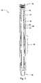
- FIG. 1is a cross-sectional view of one embodiment of a drilling jar for use with the present invention
- FIG. 2is a perspective cross-sectional view of one embodiment of a cable routed through a jar
- FIG. 3is a cross-sectional view illustrating one embodiment of one component of the jar mandrel
- FIG. 4is a perspective view illustrating one embodiment of a component of the jar housing
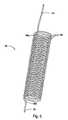
- FIG. 5is a perspective view illustrating one embodiment of a coiled cable in accordance with the invention.
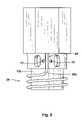
- FIG. 6is a perspective view illustrating one embodiment of the relationship between the coiled cable and components of the jar housing and jar mandrel in an expanded or partially expanded state;
- FIG. 7is a perspective view illustrating one embodiment of the relationship between the coiled cable and components of the jar housing and jar mandrel in a compressed or partially compressed state
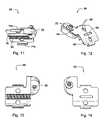
- FIG. 8is a front view illustrating one embodiment of a coiled cable passing though a recess in a component of the mandrel
- FIG. 9is a front view illustrating one embodiment of a coiled cable retained by a clamp in accordance with the invention.
- FIG. 10is a cross-sectional side view of the illustration of FIG. 9 illustrating one embodiment of a coiled cable passing through a channel in the mandrel into the central bore of the mandrel;
- FIGS. 11–14are several perspective views of one embodiment of a clamp in accordance with the invention.
- FIGS. 15–16are several perspective views of one embodiment of a complementary clamping mechanism that may be included with the clamp illustrated in FIGS. 11–14 .
- FIG. 1a drilling jar 10 adaptable for use with the present invention is illustrated.
- the drilling jar 10is illustrated very generally to illustrate various features, components, and functions that may be typical of a wide variety of drilling jars. More specific details of the drilling jar are not described in this specification and are unneeded to accurately describe apparatus and methods in accordance with the invention. For more specific details with respect to the internal functions of selected drilling jars, the reader is referred to issued patents such as U.S. Pat. No. 5,647,466 to Wenzel or U.S. Pat. No. 5,984,028 to Wilson.
- the majority of drilling jars 10include a housing 12 and a mandrel 14 inserted into the housing 12 .
- the mandrel 14is axially translatable with respect to the housing 12 to permit variation of the jar's length. That is, the mandrel 14 may slide into or out of the housing 12 .
- the mandrel 14is typically rotationally fixed with respect to the housing to allow a torque to be applied through the drilling jar 10 to other connected downhole tools.
- the jar 10includes a box end 16 and a pin end 18 to enable connection to other components or tools of a drill string.
- the jar 10provides its “jarring” effect by allowing rapid axial movement between the mandrel 14 and the housing 12 .
- This axial movementis stopped when a hammer 20 rigidly connected to the mandrel 14 comes into contact with an anvil 22 , 24 of the housing 12 .
- the hammer 20may contact a first anvil 22 to send a shock wave in a first direction up the drill string.
- the hammer 20may contact a second anvil 24 to send a shock wave in the opposite direction.
- the range of axial movement of the housing 12 with respect to the mandrel 14is typically on the order of 24 inches or less.
- a drilling jar 10may include a release mechanism 26 .
- tension or compressionis placed on the drill string, depending on the direction the shock wave is to be sent.
- the release mechanism 26serves to resist axial translation of the housing 12 with respect to the mandrel 14 caused by this tension or compression, thereby allowing potential energy to be stored in the drill string.
- the release mechanism 26may allow slight axial movement between the housing 12 and the mandrel 14 .
- the release mechanism 26reaches a threshold wherein resistance to the axial movement is released, thereby allowing the stored potential energy to cause rapid axial movement between the housing 12 and the mandrel 14 .
- the hammer 20then strikes one of the anvils 22 , 24 , causing the shock wave.
- the release mechanismmay operate using hydraulics, springs, or other methods, as desired, to provide functionality to the jar 10 .
- FIG. 2one embodiment of a pin end 18 of a selected drilling jar 10 is illustrated. Nevertheless, the technology described herein may be equally applicable to other types of drilling jars having diverse configurations. For example, as illustrated, an apparatus in accordance with the invention is installed near the pin end 18 of a drilling jar 10 . However, in other types of drilling jars 10 , it may be appropriate to install similar apparatus near the box end 16 . This may depend on the design of the mandrel 14 and the housing 12 and the space available or constraints of each particular drilling jar 10 .
- the drilling jar 10 illustrated in FIG. 2illustrates one type of drilling jar 10 that has been found suitable for use with apparatus and methods in accordance with the invention.
- the drilling jar 10 and corresponding components into which apparatus and methods in accordance the invention are integratedis the Dailey Hydraulic Drilling Jar manufactured by Weatherford Corporation.
- the readershould refer to technical materials distributed by the manufacturer.
- Other types and configurations of drilling jars 10produced by either the same or other manufacturers, may be adaptable for use with apparatus and methods in accordance with the invention. These other jars are, therefore, intended to be captured within the scope of this specification and accompanying claims.
- transmission cable or other transmission mediamay be integrated directly into drill strings. This may allow data to be transmitted at high speed from downhole drilling components, such as those located proximate a bottom hole assembly, to the surface for analysis. Data may also be transmitted from the surface to downhole components.
- a downhole-drilling jar 10may include a mandrel 14 that may slide in an axial direction with respect to a housing 12 .
- the mandrel 14may comprise multiple components 14 a , 14 b connected together.
- the housing 12may also include multiple components 12 a , 12 b connected together. That is, the mandrel components 14 a , 14 b that are connected together may function as a single rigid component 14 that may slide with respect to housing components 12 a , 12 b that may also function as a single rigid component 12 .
- the components 12 a , 12 b , 14 a , 14 bmay take on various forms, as needed, in accordance with a particular design or configuration of a drilling jar 10 .
- seals 36 , pistons 36 , or other components 36may be present between the mandrel 14 a , 14 b , and the housing 12 a , 12 b to provide bearing surfaces on which the mandrel 14 or housing 12 slides, or to retain fluids, such as hydraulic fluid, or gasses within various internal chambers 37 a , 37 b between the housing 12 and the mandrel 14 .
- a coiled transmission line 28may be inserted within the housing 12 and coiled around the mandrel 14 .
- the coiled transmission line 28is used to accommodate axial movements between the mandrel 14 and the housing 12 .
- the coil 28may stretch and compress as a spring, thereby increasing or decreasing in length.
- the coilmay include a first end 30 that may interface or be integrated into the mandrel 14 and a second end 32 that is integrated into housing 12 .
- the coil 28 and corresponding first and second ends 30 , 32are formed from a continuous section of transmission cable or other transmission media.
- one component 14 b of the mandrel 14may appear as illustrated.
- the component 14 bis specific to the drilling jar illustrated and is not necessarily representative of all or even the majority of drilling jars 10 available.
- apparatus and methods in accordance with the inventionshould not be limited to this particular configuration, the same being used only as an example.
- the mandrel component 14 bmay include an outer cylindrical surface 40 that may or may not contact the inner surface of the housing 12 .
- the mandrel component 14 bmay also include an opening 38 or junction point 38 where the mandrel component 14 b may connect, using threads or other means, to other components or sections of the mandrel 14 .
- An anti-rotation mechanism 42which may consist of a series of flat faces, may be integrated into the mandrel 14 to prevent the mandrel 14 from rotating with respect to the housing 12 .
- the mandrel component 14 bmay also be formed to include one or several apertures 44 that may provide various functions. For example, the apertures may perform tasks such as permitting the flow of fluids or gases through the mandrel component, releasing pressure buildup in chambers of the jar 10 , permit the dissipation of heat, or the like.
- a corresponding housing component 12 binto which the mandrel component 14 b slides, may appear as illustrated.
- the housing component 12 bincludes an interior surface 46 that slides with respect to and in close proximity to the corresponding outer surface 40 of the mandrel component 14 b .
- a channel 48may be formed or milled into the housing component 12 b to accommodate a transmission line.
- the channel 48may be open to permit the transmission line to transition from the housing component 12 b to another component of the housing 12 .
- An aperture 50is provided in the housing component 12 b to allow the exit of the transmission line from the housing component 12 b .
- a contoured support 52may be provided to support and relieve stress from bends present in the transmission line.
- the housing componentmay also include one or several apertures 54 , providing any of various functions such as those mentioned with respect to apertures 44 described in FIG. 3 .
- the coiled transmission line 28may include multiple coils 56 to expand and contract in a spring-like manner to accommodate axial variations in the jar's length.
- the coils 56may transition to substantially straight sections 30 , 32 by way of bends 58 a , 58 b in the coiled line 28 .
- the transmission line 28may include an outer conduit enclosing one or several transmission cables.
- the outer conduitmay be constructed of a material, such as stainless steel, to resist corrosion as well as to provide the spring-like characteristics of the coiled transmission line 28 .
- the stainless steelis sufficiently resilient to return to its original shape after being stretched or compressed.
- the transmission line 28has also been found advantageous to form the transmission line 28 from a single continuous section of conduit, although this is not mandatory. Prior to this application, the forming of a stainless steel conduit into multiple spring-like coils was not known. Continuity of the transmission line 28 prevents various problems that may arise from having multiple connections within the jar and also facilitates higher tensioning of the straight sections 30 , 32 of the transmission line 28 compared to the coils 56 .
- the coiled transmission line 28is integrated with the mandrel component 14 b and the housing component 12 b . As illustrated, the housing and mandrel components 12 b , 14 b are in an extended state 62 . Likewise, the coiled transmission line 28 is also in an extended or expanded state 62 . In selected embodiments, the coiled transmission line 28 may be in constant compression. That is, the coiled transmission line 28 may be “sprung” such that it is always in compression, whether the housing and mandrel components 12 b , 14 b are in an extended or non-extended state. This may keep the coiled transmission line 28 stable and prevent rattling or unnecessary movements of the transmission line 28 with respect to the housing and mandrel components 12 b , 14 b.
- the contoured support 52conforms to the shape or bend of the transmission line 28 as it transitions from the coiled portion to the straighter section 32 .
- a clamp 64may also be used where the coiled transmission line 28 transitions to a straighter section 30 .
- the sectionmay be routed a significant distance through the central bore 17 of the jar 10 (not shown).
- the section 30may be tensioned significantly.
- the clamp 64may serve to securely hold the transmission line and enable a significant change in tension between the coiled section 28 and the straighter section 30 .
- the section 32may also be tensioned higher than that of the coiled portion 28 .
- this section 32may be significantly shorter than the section 30 , the tension may not be as high and a clamp may not be needed.
- the bend 58 b in the conduitmay be sufficient to withstand the change in tension. Nevertheless, in selected embodiments, it may be desirable to provide a clamp at or near the bend 58 b.
- the housing and mandrel components 12 b , 14 bare in a compressed or non-extended state 62 .
- the coiled transmission line 28is also in a compressed state 66 .
- the compressed state illustrated in FIG. 7shows the approximate relationship of components when the hammer 20 strikes the lower anvil 24
- the state illustrated in FIG. 6shows a relationship of components when the hammer 20 strikes the upper anvil 22 .
- a channel 68 or recess 68may be formed in the mandrel component 14 b to route the coiled transmission line 28 to the central bore 17 of the jar 10 .
- one or several threaded apertures 70may be provided to securely mount the clamp 64 (not shown). The clamp 64 may be used to securely fix the transmission line 28 and also provide support to the bend 58 a.
- the clamp 64may be attached to the mandrel component 14 b to secure the transmission line 28 .
- the clamp 64has several tabs 74 that engage apertures 44 to provide additional strength to the clamp 64 , although this is not mandatory.
- One or several fasteners 74such as screws 74 , may be used to secure the clamp 64 to the mandrel component 14 b .
- the clamp 64may optionally include a support mount 76 to provide structural support 76 to the bend 58 a in the transmission line 28 .
- the structural support 76may include an elastomeric, plastic, metal, or other contoured support 78 to support the bend 58 a , and may be connected thereto with a fastener 80 .
- the coiled transmission line 28may be routed through a channel 82 in the wall of the mandrel component 14 b .
- several bends 84 a , 84 bmay be formed in the transmission line such that it may extend through the wall and be routed through the central bore 17 of the jar 10 .
- the clamp 64providing a clamping force on the transmission line 28 , and an optional bottom grip 81 configured to assist the clamp 64 in gripping the transmission line 28 .
- the clamp 64 and corresponding bottom grip 81may be configured to increase their grip on the transmission line 28 in response to increased tension in the line 28 .
- an increase in tension in the line 30may urge the bottom grip 81 in an upward direction. Since the bottom grip 81 is rigid and will resist going around the bend 84 , the net effect will be to squeeze the line 28 tighter, thereby providing a better grip.
- FIGS. 11 through 14various perspective views of a clamp 64 in accordance with the invention are illustrated.
- One or several apertures 86may be included in the body 96 of the clamp 64 to provide a means for attaching the clamp 64 to the mandrel component 14 b .
- the clamp body 96may also be rounded to better conform to the cylindrical contour of the mandrel component 14 b.
- a grip mechanism 90may be integrated or attached to the clamp 64 .
- the grip mechanismmay include teeth 92 or other surface textures to grip or engage the transmission line 28 .
- the grip mechanism 90may also have a rounded contour 92 to conform to the transmission line 28 .
- an aperture 88may be included in the clamp body 96 to align, connect, or both, the grip mechanism 90 to the clamp 64 .
- the clamp body 96may include one or several tabs 74 a , 74 b to engage apertures 44 in the mandrel component 14 b .
- a support 78may also be integrated into or attached to the clamp body 96 .
- the support 78may be constructed of any suitable material, including rubber, plastic, metal, and the like, and may be attached to the clamp body 96 with an adhesive or a fastener 72 , such as a washer 94 and screw 72 .
- a bottom grip 81may include a contoured surface 104 having teeth or other gripping texture to grip the transmission line 28 .
- the bottom grip 81may also include an angled portion 102 having teeth 106 or other texture 106 to grip the transmission line 28 at or near the bend 84 b (See FIG. 10 ).
- the bottom grip 81may have a bottom surface 100 that slides with respect to the bottom of the channel 68 or recess 68 .
- the bottom grip 81may move slightly toward the bend 84 b with the transmission line 30 . This may cause the teeth 106 to dig into or grip the transmission line 30 in proportion to the increased tension.
Landscapes
- Life Sciences & Earth Sciences (AREA)
- Engineering & Computer Science (AREA)
- Geology (AREA)
- Mining & Mineral Resources (AREA)
- Physics & Mathematics (AREA)
- Environmental & Geological Engineering (AREA)
- Fluid Mechanics (AREA)
- General Life Sciences & Earth Sciences (AREA)
- Geochemistry & Mineralogy (AREA)
- Marine Sciences & Fisheries (AREA)
- Mechanical Engineering (AREA)
- Electric Cable Installation (AREA)
Abstract
Description
Claims (24)
Priority Applications (1)
| Application Number | Priority Date | Filing Date | Title |
|---|---|---|---|
| US10/653,604US6991035B2 (en) | 2003-09-02 | 2003-09-02 | Drilling jar for use in a downhole network |
Applications Claiming Priority (1)
| Application Number | Priority Date | Filing Date | Title |
|---|---|---|---|
| US10/653,604US6991035B2 (en) | 2003-09-02 | 2003-09-02 | Drilling jar for use in a downhole network |
Publications (2)
| Publication Number | Publication Date |
|---|---|
| US20050045339A1 US20050045339A1 (en) | 2005-03-03 |
| US6991035B2true US6991035B2 (en) | 2006-01-31 |
Family
ID=34217929
Family Applications (1)
| Application Number | Title | Priority Date | Filing Date |
|---|---|---|---|
| US10/653,604Expired - LifetimeUS6991035B2 (en) | 2003-09-02 | 2003-09-02 | Drilling jar for use in a downhole network |
Country Status (1)
| Country | Link |
|---|---|
| US (1) | US6991035B2 (en) |
Cited By (20)
| Publication number | Priority date | Publication date | Assignee | Title |
|---|---|---|---|---|
| US20060157250A1 (en)* | 2004-12-23 | 2006-07-20 | Remote Marine Systems Limited | Improvements In or Relating to Sub Sea Control and Monitoring |
| US7132904B2 (en) | 2005-02-17 | 2006-11-07 | Intelliserv, Inc. | Apparatus for reducing noise |
| US20070018848A1 (en)* | 2002-12-23 | 2007-01-25 | Halliburton Energy Services, Inc. | Electrical connection assembly |
| US20080012569A1 (en)* | 2005-05-21 | 2008-01-17 | Hall David R | Downhole Coils |
| US20080083529A1 (en)* | 2005-05-21 | 2008-04-10 | Hall David R | Downhole Coils |
| US20090151926A1 (en)* | 2005-05-21 | 2009-06-18 | Hall David R | Inductive Power Coupler |
| US20090151932A1 (en)* | 2005-05-21 | 2009-06-18 | Hall David R | Intelligent Electrical Power Distribution System |
| US20100243324A1 (en)* | 2009-03-31 | 2010-09-30 | Intelliserv, Llc | System and method for communicating about a wellsite |
| US8130118B2 (en) | 2005-05-21 | 2012-03-06 | Schlumberger Technology Corporation | Wired tool string component |
| US8704677B2 (en) | 2008-05-23 | 2014-04-22 | Martin Scientific Llc | Reliable downhole data transmission system |
| US20150152726A1 (en)* | 2012-07-20 | 2015-06-04 | China National Petroleum Corporation | Information transmission apparatus for logging while drilling |
| US9551199B2 (en) | 2014-10-09 | 2017-01-24 | Impact Selector International, Llc | Hydraulic impact apparatus and methods |
| US9644441B2 (en) | 2014-10-09 | 2017-05-09 | Impact Selector International, Llc | Hydraulic impact apparatus and methods |
| US10218074B2 (en) | 2015-07-06 | 2019-02-26 | Baker Hughes Incorporated | Dipole antennas for wired-pipe systems |
| US10329856B2 (en) | 2015-05-19 | 2019-06-25 | Baker Hughes, A Ge Company, Llc | Logging-while-tripping system and methods |
| WO2022223691A1 (en) | 2021-04-23 | 2022-10-27 | Think And Vision Gmbh | Impact device for a drill string |
| US11506011B2 (en) | 2020-12-17 | 2022-11-22 | Saudi Arabian Oil Company | Method and apparatus of smart jarring system |
| US11585204B2 (en) | 2020-05-26 | 2023-02-21 | Heath Poulson | Crowding avoidance apparatus and method |
| US11885192B1 (en) | 2022-10-31 | 2024-01-30 | Saudi Arabian Oil Company | Wireline jarring tool and methods of use |
| US20240076958A1 (en)* | 2019-09-06 | 2024-03-07 | Optimum Petroleum Services Inc. | Downhole pressure wave generating device |
Families Citing this family (71)
| Publication number | Priority date | Publication date | Assignee | Title |
|---|---|---|---|---|
| US7253745B2 (en)* | 2000-07-19 | 2007-08-07 | Intelliserv, Inc. | Corrosion-resistant downhole transmission system |
| SE524538C2 (en)* | 2002-02-19 | 2004-08-24 | Volvo Lastvagnar Ab | Device for controlling outgoing engine torque in trucks equipped with differential locks |
| US7207396B2 (en)* | 2002-12-10 | 2007-04-24 | Intelliserv, Inc. | Method and apparatus of assessing down-hole drilling conditions |
| US7193527B2 (en)* | 2002-12-10 | 2007-03-20 | Intelliserv, Inc. | Swivel assembly |
| US7528736B2 (en)* | 2003-05-06 | 2009-05-05 | Intelliserv International Holding | Loaded transducer for downhole drilling components |
| US7193526B2 (en) | 2003-07-02 | 2007-03-20 | Intelliserv, Inc. | Downhole tool |
| US7139218B2 (en) | 2003-08-13 | 2006-11-21 | Intelliserv, Inc. | Distributed downhole drilling network |
| US7017667B2 (en)* | 2003-10-31 | 2006-03-28 | Intelliserv, Inc. | Drill string transmission line |
| US7063134B2 (en)* | 2004-06-24 | 2006-06-20 | Tenneco Automotive Operating Company Inc. | Combined muffler/heat exchanger |
| US7200070B2 (en)* | 2004-06-28 | 2007-04-03 | Intelliserv, Inc. | Downhole drilling network using burst modulation techniques |
| US7319410B2 (en)* | 2004-06-28 | 2008-01-15 | Intelliserv, Inc. | Downhole transmission system |
| US7253671B2 (en)* | 2004-06-28 | 2007-08-07 | Intelliserv, Inc. | Apparatus and method for compensating for clock drift in downhole drilling components |
| US20060062249A1 (en)* | 2004-06-28 | 2006-03-23 | Hall David R | Apparatus and method for adjusting bandwidth allocation in downhole drilling networks |
| US7091810B2 (en) | 2004-06-28 | 2006-08-15 | Intelliserv, Inc. | Element of an inductive coupler |
| US7248177B2 (en)* | 2004-06-28 | 2007-07-24 | Intelliserv, Inc. | Down hole transmission system |
| US20050284659A1 (en)* | 2004-06-28 | 2005-12-29 | Hall David R | Closed-loop drilling system using a high-speed communications network |
| US7198118B2 (en)* | 2004-06-28 | 2007-04-03 | Intelliserv, Inc. | Communication adapter for use with a drilling component |
| US7093654B2 (en)* | 2004-07-22 | 2006-08-22 | Intelliserv, Inc. | Downhole component with a pressure equalization passageway |
| US7274304B2 (en)* | 2004-07-27 | 2007-09-25 | Intelliserv, Inc. | System for loading executable code into volatile memory in a downhole tool |
| US7201240B2 (en)* | 2004-07-27 | 2007-04-10 | Intelliserv, Inc. | Biased insert for installing data transmission components in downhole drilling pipe |
| US7165633B2 (en)* | 2004-09-28 | 2007-01-23 | Intelliserv, Inc. | Drilling fluid filter |
| US7303029B2 (en)* | 2004-09-28 | 2007-12-04 | Intelliserv, Inc. | Filter for a drill string |
| US7135933B2 (en) | 2004-09-29 | 2006-11-14 | Intelliserv, Inc. | System for adjusting frequency of electrical output pulses derived from an oscillator |
| US8033328B2 (en)* | 2004-11-05 | 2011-10-11 | Schlumberger Technology Corporation | Downhole electric power generator |
| US7548068B2 (en) | 2004-11-30 | 2009-06-16 | Intelliserv International Holding, Ltd. | System for testing properties of a network |
| US7298287B2 (en)* | 2005-02-04 | 2007-11-20 | Intelliserv, Inc. | Transmitting data through a downhole environment |
| US20060256718A1 (en)* | 2005-05-16 | 2006-11-16 | Hall David R | Apparatus for Regulating Bandwidth |
| US7212040B2 (en)* | 2005-05-16 | 2007-05-01 | Intelliserv, Inc. | Stabilization of state-holding circuits at high temperatures |
| US7382273B2 (en)* | 2005-05-21 | 2008-06-03 | Hall David R | Wired tool string component |
| US7277026B2 (en)* | 2005-05-21 | 2007-10-02 | Hall David R | Downhole component with multiple transmission elements |
| US7268697B2 (en)* | 2005-07-20 | 2007-09-11 | Intelliserv, Inc. | Laterally translatable data transmission apparatus |
| US8826972B2 (en)* | 2005-07-28 | 2014-09-09 | Intelliserv, Llc | Platform for electrically coupling a component to a downhole transmission line |
| US20070023185A1 (en)* | 2005-07-28 | 2007-02-01 | Hall David R | Downhole Tool with Integrated Circuit |
| US7275594B2 (en) | 2005-07-29 | 2007-10-02 | Intelliserv, Inc. | Stab guide |
| US7299867B2 (en)* | 2005-09-12 | 2007-11-27 | Intelliserv, Inc. | Hanger mounted in the bore of a tubular component |
| US7571780B2 (en)* | 2006-03-24 | 2009-08-11 | Hall David R | Jack element for a drill bit |
| US8297375B2 (en) | 2005-11-21 | 2012-10-30 | Schlumberger Technology Corporation | Downhole turbine |
| US8267196B2 (en) | 2005-11-21 | 2012-09-18 | Schlumberger Technology Corporation | Flow guide actuation |
| US8360174B2 (en) | 2006-03-23 | 2013-01-29 | Schlumberger Technology Corporation | Lead the bit rotary steerable tool |
| US8522897B2 (en) | 2005-11-21 | 2013-09-03 | Schlumberger Technology Corporation | Lead the bit rotary steerable tool |
| US7298286B2 (en)* | 2006-02-06 | 2007-11-20 | Hall David R | Apparatus for interfacing with a transmission path |
| US7350565B2 (en)* | 2006-02-08 | 2008-04-01 | Hall David R | Self-expandable cylinder in a downhole tool |
| US7598886B2 (en) | 2006-04-21 | 2009-10-06 | Hall David R | System and method for wirelessly communicating with a downhole drill string |
| US7572134B2 (en)* | 2006-07-03 | 2009-08-11 | Hall David R | Centering assembly for an electric downhole connection |
| US7649475B2 (en)* | 2007-01-09 | 2010-01-19 | Hall David R | Tool string direct electrical connection |
| US7488194B2 (en)* | 2006-07-03 | 2009-02-10 | Hall David R | Downhole data and/or power transmission system |
| US7404725B2 (en)* | 2006-07-03 | 2008-07-29 | Hall David R | Wiper for tool string direct electrical connection |
| EP1913230B1 (en)* | 2006-07-06 | 2011-04-27 | Halliburton Energy Services, Inc. | Tubular member connection |
| US7656309B2 (en)* | 2006-07-06 | 2010-02-02 | Hall David R | System and method for sharing information between downhole drill strings |
| NO325507B1 (en)* | 2006-07-13 | 2008-05-26 | Petrotools As | Apparatus for mechanical release of a hammer in a well tool |
| US7527105B2 (en)* | 2006-11-14 | 2009-05-05 | Hall David R | Power and/or data connection in a downhole component |
| US7617877B2 (en)* | 2007-02-27 | 2009-11-17 | Hall David R | Method of manufacturing downhole tool string components |
| US7934570B2 (en)* | 2007-06-12 | 2011-05-03 | Schlumberger Technology Corporation | Data and/or PowerSwivel |
| US7730957B2 (en)* | 2007-08-01 | 2010-06-08 | Halliburton Energy Services, Inc. | Well tool with line and installation method |
| US7537053B1 (en) | 2008-01-29 | 2009-05-26 | Hall David R | Downhole electrical connection |
| US8061443B2 (en)* | 2008-04-24 | 2011-11-22 | Schlumberger Technology Corporation | Downhole sample rate system |
| US8237584B2 (en)* | 2008-04-24 | 2012-08-07 | Schlumberger Technology Corporation | Changing communication priorities for downhole LWD/MWD applications |
| US7980331B2 (en)* | 2009-01-23 | 2011-07-19 | Schlumberger Technology Corporation | Accessible downhole power assembly |
| US8028768B2 (en)* | 2009-03-17 | 2011-10-04 | Schlumberger Technology Corporation | Displaceable plug in a tool string filter |
| WO2011153180A2 (en)* | 2010-06-03 | 2011-12-08 | Bp Corporation North America Inc. | Selective control of charging, firing, amount of force, and/or direction of fore of one or more downhole jars |
| US9255451B2 (en) | 2013-01-29 | 2016-02-09 | Baker Hughes Incorporated | Tube locking mechanism for downhole components |
| US9759017B2 (en) | 2013-01-30 | 2017-09-12 | Baker Hughes Incorporated | Maintaining tension of a transmission line in a tubular |
| EP2959097B1 (en)* | 2013-02-21 | 2018-04-18 | Halliburton Energy Services, Inc. | Method and system for directing control lines along a travel joint |
| US9850718B2 (en)* | 2013-08-07 | 2017-12-26 | Baker Hughes, A Ge Company Llc | Retention device for drill pipe transmission line |
| US9512682B2 (en) | 2013-11-22 | 2016-12-06 | Baker Hughes Incorporated | Wired pipe and method of manufacturing wired pipe |
| US10577872B2 (en) | 2015-07-28 | 2020-03-03 | Halliburton Energy Services, Inc. | Curbed links for wiring conduit |
| US12338692B2 (en)* | 2023-05-31 | 2025-06-24 | Halliburton Energy Services, Inc. | Swivel sub with biasing member |
| US12158043B1 (en)* | 2023-05-31 | 2024-12-03 | Halliburton Energy Services, Inc. | Bi-directional swivel sub with lugs |
| US12398607B2 (en)* | 2023-05-31 | 2025-08-26 | Halliburton Energy Services, Inc. | Swivel sub with intermediate lug for extended rotation |
| US20230407710A1 (en)* | 2023-07-24 | 2023-12-21 | Sigurd Solem | Downhole signal-conducting and power-conducting flexible cable |
| CN120251108B (en)* | 2025-06-05 | 2025-08-15 | 斯伦贝谢油田技术(山东)有限公司 | Telescopic type downhole connection device of (c) |
Citations (112)
| Publication number | Priority date | Publication date | Assignee | Title |
|---|---|---|---|---|
| US749633A (en) | 1904-01-12 | Electrical hose signaling apparatus | ||
| US2178931A (en) | 1937-04-03 | 1939-11-07 | Phillips Petroleum Co | Combination fluid conduit and electrical conductor |
| US2197392A (en) | 1939-11-13 | 1940-04-16 | Geophysical Res Corp | Drill stem section |
| US2249769A (en) | 1938-11-28 | 1941-07-22 | Schlumberger Well Surv Corp | Electrical system for exploring drill holes |
| US2301783A (en) | 1940-03-08 | 1942-11-10 | Robert E Lee | Insulated electrical conductor for pipes |
| US2354887A (en) | 1942-10-29 | 1944-08-01 | Stanolind Oil & Gas Co | Well signaling system |
| US2379800A (en) | 1941-09-11 | 1945-07-03 | Texas Co | Signal transmission system |
| US2414719A (en) | 1942-04-25 | 1947-01-21 | Stanolind Oil & Gas Co | Transmission system |
| US2531120A (en) | 1947-06-02 | 1950-11-21 | Harry L Feaster | Well-drilling apparatus |
| US2633414A (en) | 1947-06-16 | 1953-03-31 | Pechiney Prod Chimiques Sa | Protective liner for autoclaves |
| US2659773A (en) | 1949-06-07 | 1953-11-17 | Bell Telephone Labor Inc | Inverted grounded emitter transistor amplifier |
| US2662123A (en) | 1951-02-24 | 1953-12-08 | Bell Telephone Labor Inc | Electrical transmission system including bilateral transistor amplifier |
| US2748358A (en) | 1952-01-08 | 1956-05-29 | Signal Oil & Gas Co | Combination oil well tubing and electrical cable construction |
| US2974303A (en) | 1957-02-08 | 1961-03-07 | Schlumberger Well Surv Corp | Electrical systems for borehole apparatus |
| US2982360A (en) | 1956-10-12 | 1961-05-02 | Int Nickel Co | Protection of steel oil and/or gas well tubing |
| US3079549A (en) | 1957-07-05 | 1963-02-26 | Philip W Martin | Means and techniques for logging well bores |
| US3090031A (en) | 1959-09-29 | 1963-05-14 | Texaco Inc | Signal transmission system |
| US3170137A (en) | 1962-07-12 | 1965-02-16 | California Research Corp | Method of improving electrical signal transmission in wells |
| US3186222A (en) | 1960-07-28 | 1965-06-01 | Mccullough Tool Co | Well signaling system |
| US3194886A (en) | 1961-12-22 | 1965-07-13 | Creed & Co Ltd | Hall effect receiver for mark and space coded signals |
| US3209323A (en) | 1962-10-02 | 1965-09-28 | Texaco Inc | Information retrieval system for logging while drilling |
| US3227973A (en) | 1962-01-31 | 1966-01-04 | Reginald I Gray | Transformer |
| US3253245A (en) | 1965-03-05 | 1966-05-24 | Chevron Res | Electrical signal transmission for well drilling |
| US3518608A (en) | 1968-10-28 | 1970-06-30 | Shell Oil Co | Telemetry drill pipe with thread electrode |
| US3696332A (en) | 1970-05-25 | 1972-10-03 | Shell Oil Co | Telemetering drill string with self-cleaning connectors |
| US3793632A (en) | 1971-03-31 | 1974-02-19 | W Still | Telemetry system for drill bore holes |
| US3807502A (en) | 1973-04-12 | 1974-04-30 | Exxon Production Research Co | Method for installing an electric conductor in a drill string |
| US3879097A (en) | 1974-01-25 | 1975-04-22 | Continental Oil Co | Electrical connectors for telemetering drill strings |
| US3930220A (en) | 1973-09-12 | 1975-12-30 | Sun Oil Co Pennsylvania | Borehole signalling by acoustic energy |
| US3957118A (en) | 1974-09-18 | 1976-05-18 | Exxon Production Research Company | Cable system for use in a pipe string and method for installing and using the same |
| US3989330A (en) | 1975-11-10 | 1976-11-02 | Cullen Roy H | Electrical kelly cock assembly |
| US4012092A (en) | 1976-03-29 | 1977-03-15 | Godbey Josiah J | Electrical two-way transmission system for tubular fluid conductors and method of construction |
| US4087781A (en) | 1974-07-01 | 1978-05-02 | Raytheon Company | Electromagnetic lithosphere telemetry system |
| US4095865A (en) | 1977-05-23 | 1978-06-20 | Shell Oil Company | Telemetering drill string with piped electrical conductor |
| US4121193A (en) | 1977-06-23 | 1978-10-17 | Shell Oil Company | Kelly and kelly cock assembly for hard-wired telemetry system |
| US4126848A (en) | 1976-12-23 | 1978-11-21 | Shell Oil Company | Drill string telemeter system |
| US4215426A (en) | 1978-05-01 | 1980-07-29 | Frederick Klatt | Telemetry and power transmission for enclosed fluid systems |
| US4220381A (en) | 1978-04-07 | 1980-09-02 | Shell Oil Company | Drill pipe telemetering system with electrodes exposed to mud |
| US4348672A (en) | 1981-03-04 | 1982-09-07 | Tele-Drill, Inc. | Insulated drill collar gap sub assembly for a toroidal coupled telemetry system |
| US4445734A (en) | 1981-12-04 | 1984-05-01 | Hughes Tool Company | Telemetry drill pipe with pressure sensitive contacts |
| US4496203A (en) | 1981-05-22 | 1985-01-29 | Coal Industry (Patents) Limited | Drill pipe sections |
| US4537457A (en) | 1983-04-28 | 1985-08-27 | Exxon Production Research Co. | Connector for providing electrical continuity across a threaded connection |
| US4578675A (en) | 1982-09-30 | 1986-03-25 | Macleod Laboratories, Inc. | Apparatus and method for logging wells while drilling |
| US4605268A (en) | 1982-11-08 | 1986-08-12 | Nl Industries, Inc. | Transformer cable connector |
| US4660910A (en) | 1984-12-27 | 1987-04-28 | Schlumberger Technology Corporation | Apparatus for electrically interconnecting multi-sectional well tools |
| US4683944A (en) | 1985-05-06 | 1987-08-04 | Innotech Energy Corporation | Drill pipes and casings utilizing multi-conduit tubulars |
| US4698631A (en) | 1986-12-17 | 1987-10-06 | Hughes Tool Company | Surface acoustic wave pipe identification system |
| US4722402A (en) | 1986-01-24 | 1988-02-02 | Weldon James M | Electromagnetic drilling apparatus and method |
| US4785247A (en) | 1983-06-27 | 1988-11-15 | Nl Industries, Inc. | Drill stem logging with electromagnetic waves and electrostatically-shielded and inductively-coupled transmitter and receiver elements |
| US4788544A (en) | 1987-01-08 | 1988-11-29 | Hughes Tool Company - Usa | Well bore data transmission system |
| US4806928A (en) | 1987-07-16 | 1989-02-21 | Schlumberger Technology Corporation | Apparatus for electromagnetically coupling power and data signals between well bore apparatus and the surface |
| US4884071A (en) | 1987-01-08 | 1989-11-28 | Hughes Tool Company | Wellbore tool with hall effect coupling |
| US4901069A (en) | 1987-07-16 | 1990-02-13 | Schlumberger Technology Corporation | Apparatus for electromagnetically coupling power and data signals between a first unit and a second unit and in particular between well bore apparatus and the surface |
| US4914433A (en) | 1988-04-19 | 1990-04-03 | Hughes Tool Company | Conductor system for well bore data transmission |
| EP0399987A1 (en) | 1989-05-23 | 1990-11-28 | Smet-Hole, Naamloze Vennootschap | Device and method for signal transmission in drill stems |
| US5008664A (en) | 1990-01-23 | 1991-04-16 | Quantum Solutions, Inc. | Apparatus for inductively coupling signals between a downhole sensor and the surface |
| US5052941A (en) | 1988-12-13 | 1991-10-01 | Schlumberger Technology Corporation | Inductive-coupling connector for a well head equipment |
| US5148408A (en) | 1990-11-05 | 1992-09-15 | Teleco Oilfield Services Inc. | Acoustic data transmission method |
| US5248857A (en) | 1990-04-27 | 1993-09-28 | Compagnie Generale De Geophysique | Apparatus for the acquisition of a seismic signal transmitted by a rotating drill bit |
| US5278550A (en) | 1992-01-14 | 1994-01-11 | Schlumberger Technology Corporation | Apparatus and method for retrieving and/or communicating with downhole equipment |
| US5302138A (en) | 1992-03-18 | 1994-04-12 | Shields Winston E | Electrical coupler with watertight fitting |
| US5311661A (en) | 1992-10-19 | 1994-05-17 | Packless Metal Hose Inc. | Method of pointing and corrugating heat exchange tubing |
| US5332049A (en) | 1992-09-29 | 1994-07-26 | Brunswick Corporation | Composite drill pipe |
| US5334801A (en) | 1989-11-24 | 1994-08-02 | Framo Developments (Uk) Limited | Pipe system with electrical conductors |
| US5371496A (en) | 1991-04-18 | 1994-12-06 | Minnesota Mining And Manufacturing Company | Two-part sensor with transformer power coupling and optical signal coupling |
| US5455573A (en) | 1994-04-22 | 1995-10-03 | Panex Corporation | Inductive coupler for well tools |
| US5454605A (en) | 1993-06-15 | 1995-10-03 | Hydril Company | Tool joint connection with interlocking wedge threads |
| US5505502A (en) | 1993-06-09 | 1996-04-09 | Shell Oil Company | Multiple-seal underwater pipe-riser connector |
| US5517843A (en) | 1994-03-16 | 1996-05-21 | Shaw Industries, Ltd. | Method for making upset ends on metal pipe and resulting product |
| US5521592A (en) | 1993-07-27 | 1996-05-28 | Schlumberger Technology Corporation | Method and apparatus for transmitting information relating to the operation of a downhole electrical device |
| US5558532A (en)* | 1993-08-04 | 1996-09-24 | Cooper Cameron Corporation | Electrical connection |
| US5568448A (en) | 1991-04-25 | 1996-10-22 | Mitsubishi Denki Kabushiki Kaisha | System for transmitting a signal |
| US5650983A (en) | 1993-04-28 | 1997-07-22 | Sony Corporation | Printed circuit board magnetic head for magneto-optical recording device |
| US5691712A (en) | 1995-07-25 | 1997-11-25 | Schlumberger Technology Corporation | Multiple wellbore tool apparatus including a plurality of microprocessor implemented wellbore tools for operating a corresponding plurality of included wellbore tools and acoustic transducers in response to stimulus signals and acoustic signals |
| USRE35790E (en) | 1990-08-27 | 1998-05-12 | Baroid Technology, Inc. | System for drilling deviated boreholes |
| US5810401A (en) | 1996-05-07 | 1998-09-22 | Frank's Casing Crew And Rental Tools, Inc. | Threaded tool joint with dual mating shoulders |
| US5833490A (en) | 1995-10-06 | 1998-11-10 | Pes, Inc. | High pressure instrument wire connector |
| US5853199A (en) | 1995-09-18 | 1998-12-29 | Grant Prideco, Inc. | Fatigue resistant drill pipe |
| US5856710A (en) | 1997-08-29 | 1999-01-05 | General Motors Corporation | Inductively coupled energy and communication apparatus |
| US5898408A (en) | 1995-10-25 | 1999-04-27 | Larsen Electronics, Inc. | Window mounted mobile antenna system using annular ring aperture coupling |
| US5908212A (en) | 1997-05-02 | 1999-06-01 | Grant Prideco, Inc. | Ultra high torque double shoulder tool joint |
| US5924499A (en) | 1997-04-21 | 1999-07-20 | Halliburton Energy Services, Inc. | Acoustic data link and formation property sensor for downhole MWD system |
| US5942990A (en) | 1997-10-24 | 1999-08-24 | Halliburton Energy Services, Inc. | Electromagnetic signal repeater and method for use of same |
| US5955966A (en) | 1996-04-09 | 1999-09-21 | Schlumberger Technology Corporation | Signal recognition system for wellbore telemetry |
| US5959547A (en) | 1995-02-09 | 1999-09-28 | Baker Hughes Incorporated | Well control systems employing downhole network |
| US5971072A (en) | 1997-09-22 | 1999-10-26 | Schlumberger Technology Corporation | Inductive coupler activated completion system |
| US6030004A (en) | 1997-12-08 | 2000-02-29 | Shaw Industries | High torque threaded tool joint for drill pipe and other drill stem components |
| US6041872A (en) | 1998-11-04 | 2000-03-28 | Gas Research Institute | Disposable telemetry cable deployment system |
| US6045165A (en) | 1997-05-30 | 2000-04-04 | Sumitomo Metal Industries, Ltd. | Threaded connection tubular goods |
| US6046685A (en) | 1996-09-23 | 2000-04-04 | Baker Hughes Incorporated | Redundant downhole production well control system and method |
| US6057784A (en) | 1997-09-02 | 2000-05-02 | Schlumberger Technology Corporatioin | Apparatus and system for making at-bit measurements while drilling |
| US6104707A (en) | 1989-04-28 | 2000-08-15 | Videocom, Inc. | Transformer coupler for communication over various lines |
| US6108268A (en) | 1998-01-12 | 2000-08-22 | The Regents Of The University Of California | Impedance matched joined drill pipe for improved acoustic transmission |
| US6123561A (en) | 1998-07-14 | 2000-09-26 | Aps Technology, Inc. | Electrical coupling for a multisection conduit such as a drill pipe |
| US6141763A (en) | 1998-09-01 | 2000-10-31 | Hewlett-Packard Company | Self-powered network access point |
| US6173334B1 (en) | 1997-10-08 | 2001-01-09 | Hitachi, Ltd. | Network system including a plurality of lan systems and an intermediate network having independent address schemes |
| US6177882B1 (en) | 1997-12-01 | 2001-01-23 | Halliburton Energy Services, Inc. | Electromagnetic-to-acoustic and acoustic-to-electromagnetic repeaters and methods for use of same |
| US6188223B1 (en) | 1996-09-03 | 2001-02-13 | Scientific Drilling International | Electric field borehole telemetry |
| US6196335B1 (en) | 1998-06-29 | 2001-03-06 | Dresser Industries, Inc. | Enhancement of drill bit seismics through selection of events monitored at the drill bit |
| US6209632B1 (en) | 1995-06-12 | 2001-04-03 | Marvin L. Holbert | Subsurface signal transmitting apparatus |
| US6223826B1 (en) | 1999-05-24 | 2001-05-01 | Digital Control, Inc. | Auto-extending/retracting electrically isolated conductors in a segmented drill string |
| US6367565B1 (en) | 1998-03-27 | 2002-04-09 | David R. Hall | Means for detecting subterranean formations and monitoring the operation of a down-hole fluid driven percussive piston |
| US6392317B1 (en) | 2000-08-22 | 2002-05-21 | David R. Hall | Annular wire harness for use in drill pipe |
| US20020135179A1 (en) | 2001-03-23 | 2002-09-26 | Boyle Bruce W. | Low-loss inductive couplers for use in wired pipe strings |
| US6481495B1 (en)* | 2000-09-25 | 2002-11-19 | Robert W. Evans | Downhole tool with electrical conductor |
| US20020193004A1 (en) | 2001-06-14 | 2002-12-19 | Boyle Bruce W. | Wired pipe joint with current-loop inductive couplers |
| US20030070842A1 (en) | 2001-10-12 | 2003-04-17 | Bailey Thomas F. | Methods and apparatus to control downhole tools |
| US20030147360A1 (en)* | 2002-02-06 | 2003-08-07 | Michael Nero | Automated wellbore apparatus |
| US20030213598A1 (en) | 2002-05-15 | 2003-11-20 | Hughes William James | Tubing containing electrical wiring insert |
| US6655464B2 (en) | 1999-05-24 | 2003-12-02 | Merlin Technology Inc | Auto-extending/retracting electrically isolated conductors in a segmented drill string |
| US6670880B1 (en) | 2000-07-19 | 2003-12-30 | Novatek Engineering, Inc. | Downhole data transmission system |
| US20040150533A1 (en)* | 2003-02-04 | 2004-08-05 | Hall David R. | Downhole tool adapted for telemetry |
- 2003
- 2003-09-02USUS10/653,604patent/US6991035B2/ennot_activeExpired - Lifetime
Patent Citations (117)
| Publication number | Priority date | Publication date | Assignee | Title |
|---|---|---|---|---|
| US749633A (en) | 1904-01-12 | Electrical hose signaling apparatus | ||
| US2178931A (en) | 1937-04-03 | 1939-11-07 | Phillips Petroleum Co | Combination fluid conduit and electrical conductor |
| US2249769A (en) | 1938-11-28 | 1941-07-22 | Schlumberger Well Surv Corp | Electrical system for exploring drill holes |
| US2197392A (en) | 1939-11-13 | 1940-04-16 | Geophysical Res Corp | Drill stem section |
| US2301783A (en) | 1940-03-08 | 1942-11-10 | Robert E Lee | Insulated electrical conductor for pipes |
| US2379800A (en) | 1941-09-11 | 1945-07-03 | Texas Co | Signal transmission system |
| US2414719A (en) | 1942-04-25 | 1947-01-21 | Stanolind Oil & Gas Co | Transmission system |
| US2354887A (en) | 1942-10-29 | 1944-08-01 | Stanolind Oil & Gas Co | Well signaling system |
| US2531120A (en) | 1947-06-02 | 1950-11-21 | Harry L Feaster | Well-drilling apparatus |
| US2633414A (en) | 1947-06-16 | 1953-03-31 | Pechiney Prod Chimiques Sa | Protective liner for autoclaves |
| US2659773A (en) | 1949-06-07 | 1953-11-17 | Bell Telephone Labor Inc | Inverted grounded emitter transistor amplifier |
| US2662123A (en) | 1951-02-24 | 1953-12-08 | Bell Telephone Labor Inc | Electrical transmission system including bilateral transistor amplifier |
| US2748358A (en) | 1952-01-08 | 1956-05-29 | Signal Oil & Gas Co | Combination oil well tubing and electrical cable construction |
| US2982360A (en) | 1956-10-12 | 1961-05-02 | Int Nickel Co | Protection of steel oil and/or gas well tubing |
| US2974303A (en) | 1957-02-08 | 1961-03-07 | Schlumberger Well Surv Corp | Electrical systems for borehole apparatus |
| US3079549A (en) | 1957-07-05 | 1963-02-26 | Philip W Martin | Means and techniques for logging well bores |
| US3090031A (en) | 1959-09-29 | 1963-05-14 | Texaco Inc | Signal transmission system |
| US3186222A (en) | 1960-07-28 | 1965-06-01 | Mccullough Tool Co | Well signaling system |
| US3194886A (en) | 1961-12-22 | 1965-07-13 | Creed & Co Ltd | Hall effect receiver for mark and space coded signals |
| US3227973A (en) | 1962-01-31 | 1966-01-04 | Reginald I Gray | Transformer |
| US3170137A (en) | 1962-07-12 | 1965-02-16 | California Research Corp | Method of improving electrical signal transmission in wells |
| US3209323A (en) | 1962-10-02 | 1965-09-28 | Texaco Inc | Information retrieval system for logging while drilling |
| US3253245A (en) | 1965-03-05 | 1966-05-24 | Chevron Res | Electrical signal transmission for well drilling |
| US3518608A (en) | 1968-10-28 | 1970-06-30 | Shell Oil Co | Telemetry drill pipe with thread electrode |
| US3696332A (en) | 1970-05-25 | 1972-10-03 | Shell Oil Co | Telemetering drill string with self-cleaning connectors |
| US3793632A (en) | 1971-03-31 | 1974-02-19 | W Still | Telemetry system for drill bore holes |
| US3807502A (en) | 1973-04-12 | 1974-04-30 | Exxon Production Research Co | Method for installing an electric conductor in a drill string |
| US3930220A (en) | 1973-09-12 | 1975-12-30 | Sun Oil Co Pennsylvania | Borehole signalling by acoustic energy |
| US3879097A (en) | 1974-01-25 | 1975-04-22 | Continental Oil Co | Electrical connectors for telemetering drill strings |
| US4087781A (en) | 1974-07-01 | 1978-05-02 | Raytheon Company | Electromagnetic lithosphere telemetry system |
| US3957118A (en) | 1974-09-18 | 1976-05-18 | Exxon Production Research Company | Cable system for use in a pipe string and method for installing and using the same |
| US3989330A (en) | 1975-11-10 | 1976-11-02 | Cullen Roy H | Electrical kelly cock assembly |
| US4012092A (en) | 1976-03-29 | 1977-03-15 | Godbey Josiah J | Electrical two-way transmission system for tubular fluid conductors and method of construction |
| US4126848A (en) | 1976-12-23 | 1978-11-21 | Shell Oil Company | Drill string telemeter system |
| US4095865A (en) | 1977-05-23 | 1978-06-20 | Shell Oil Company | Telemetering drill string with piped electrical conductor |
| US4121193A (en) | 1977-06-23 | 1978-10-17 | Shell Oil Company | Kelly and kelly cock assembly for hard-wired telemetry system |
| US4220381A (en) | 1978-04-07 | 1980-09-02 | Shell Oil Company | Drill pipe telemetering system with electrodes exposed to mud |
| US4215426A (en) | 1978-05-01 | 1980-07-29 | Frederick Klatt | Telemetry and power transmission for enclosed fluid systems |
| US4348672A (en) | 1981-03-04 | 1982-09-07 | Tele-Drill, Inc. | Insulated drill collar gap sub assembly for a toroidal coupled telemetry system |
| US4496203A (en) | 1981-05-22 | 1985-01-29 | Coal Industry (Patents) Limited | Drill pipe sections |
| US4445734A (en) | 1981-12-04 | 1984-05-01 | Hughes Tool Company | Telemetry drill pipe with pressure sensitive contacts |
| US4578675A (en) | 1982-09-30 | 1986-03-25 | Macleod Laboratories, Inc. | Apparatus and method for logging wells while drilling |
| US4605268A (en) | 1982-11-08 | 1986-08-12 | Nl Industries, Inc. | Transformer cable connector |
| US4537457A (en) | 1983-04-28 | 1985-08-27 | Exxon Production Research Co. | Connector for providing electrical continuity across a threaded connection |
| US4785247A (en) | 1983-06-27 | 1988-11-15 | Nl Industries, Inc. | Drill stem logging with electromagnetic waves and electrostatically-shielded and inductively-coupled transmitter and receiver elements |
| US4660910A (en) | 1984-12-27 | 1987-04-28 | Schlumberger Technology Corporation | Apparatus for electrically interconnecting multi-sectional well tools |
| US4924949A (en) | 1985-05-06 | 1990-05-15 | Pangaea Enterprises, Inc. | Drill pipes and casings utilizing multi-conduit tubulars |
| US4683944A (en) | 1985-05-06 | 1987-08-04 | Innotech Energy Corporation | Drill pipes and casings utilizing multi-conduit tubulars |
| US4722402A (en) | 1986-01-24 | 1988-02-02 | Weldon James M | Electromagnetic drilling apparatus and method |
| US4698631A (en) | 1986-12-17 | 1987-10-06 | Hughes Tool Company | Surface acoustic wave pipe identification system |
| US4884071A (en) | 1987-01-08 | 1989-11-28 | Hughes Tool Company | Wellbore tool with hall effect coupling |
| US4788544A (en) | 1987-01-08 | 1988-11-29 | Hughes Tool Company - Usa | Well bore data transmission system |
| US4806928A (en) | 1987-07-16 | 1989-02-21 | Schlumberger Technology Corporation | Apparatus for electromagnetically coupling power and data signals between well bore apparatus and the surface |
| US4901069A (en) | 1987-07-16 | 1990-02-13 | Schlumberger Technology Corporation | Apparatus for electromagnetically coupling power and data signals between a first unit and a second unit and in particular between well bore apparatus and the surface |
| US4914433A (en) | 1988-04-19 | 1990-04-03 | Hughes Tool Company | Conductor system for well bore data transmission |
| US5052941A (en) | 1988-12-13 | 1991-10-01 | Schlumberger Technology Corporation | Inductive-coupling connector for a well head equipment |
| US6104707A (en) | 1989-04-28 | 2000-08-15 | Videocom, Inc. | Transformer coupler for communication over various lines |
| EP0399987A1 (en) | 1989-05-23 | 1990-11-28 | Smet-Hole, Naamloze Vennootschap | Device and method for signal transmission in drill stems |
| WO1990014497A2 (en) | 1989-05-23 | 1990-11-29 | Eastman Christensen Gmbh | Process and device for transmitting data signals and/or control signals in a pipe train |
| US5334801A (en) | 1989-11-24 | 1994-08-02 | Framo Developments (Uk) Limited | Pipe system with electrical conductors |
| US5008664A (en) | 1990-01-23 | 1991-04-16 | Quantum Solutions, Inc. | Apparatus for inductively coupling signals between a downhole sensor and the surface |
| US5248857A (en) | 1990-04-27 | 1993-09-28 | Compagnie Generale De Geophysique | Apparatus for the acquisition of a seismic signal transmitted by a rotating drill bit |
| USRE35790E (en) | 1990-08-27 | 1998-05-12 | Baroid Technology, Inc. | System for drilling deviated boreholes |
| US5148408A (en) | 1990-11-05 | 1992-09-15 | Teleco Oilfield Services Inc. | Acoustic data transmission method |
| US5371496A (en) | 1991-04-18 | 1994-12-06 | Minnesota Mining And Manufacturing Company | Two-part sensor with transformer power coupling and optical signal coupling |
| US5568448A (en) | 1991-04-25 | 1996-10-22 | Mitsubishi Denki Kabushiki Kaisha | System for transmitting a signal |
| US5278550A (en) | 1992-01-14 | 1994-01-11 | Schlumberger Technology Corporation | Apparatus and method for retrieving and/or communicating with downhole equipment |
| US5302138A (en) | 1992-03-18 | 1994-04-12 | Shields Winston E | Electrical coupler with watertight fitting |
| US5332049A (en) | 1992-09-29 | 1994-07-26 | Brunswick Corporation | Composite drill pipe |
| US5311661A (en) | 1992-10-19 | 1994-05-17 | Packless Metal Hose Inc. | Method of pointing and corrugating heat exchange tubing |
| US5650983A (en) | 1993-04-28 | 1997-07-22 | Sony Corporation | Printed circuit board magnetic head for magneto-optical recording device |
| US5505502A (en) | 1993-06-09 | 1996-04-09 | Shell Oil Company | Multiple-seal underwater pipe-riser connector |
| US5454605A (en) | 1993-06-15 | 1995-10-03 | Hydril Company | Tool joint connection with interlocking wedge threads |
| US5521592A (en) | 1993-07-27 | 1996-05-28 | Schlumberger Technology Corporation | Method and apparatus for transmitting information relating to the operation of a downhole electrical device |
| US5558532A (en)* | 1993-08-04 | 1996-09-24 | Cooper Cameron Corporation | Electrical connection |
| US5743301A (en) | 1994-03-16 | 1998-04-28 | Shaw Industries Ltd. | Metal pipe having upset ends |
| US5517843A (en) | 1994-03-16 | 1996-05-21 | Shaw Industries, Ltd. | Method for making upset ends on metal pipe and resulting product |
| US5455573A (en) | 1994-04-22 | 1995-10-03 | Panex Corporation | Inductive coupler for well tools |
| US5959547A (en) | 1995-02-09 | 1999-09-28 | Baker Hughes Incorporated | Well control systems employing downhole network |
| US6209632B1 (en) | 1995-06-12 | 2001-04-03 | Marvin L. Holbert | Subsurface signal transmitting apparatus |
| US6405795B2 (en) | 1995-06-12 | 2002-06-18 | Weatherford/Lamb, Inc. | Subsurface signal transmitting apparatus |
| US5691712A (en) | 1995-07-25 | 1997-11-25 | Schlumberger Technology Corporation | Multiple wellbore tool apparatus including a plurality of microprocessor implemented wellbore tools for operating a corresponding plurality of included wellbore tools and acoustic transducers in response to stimulus signals and acoustic signals |
| US5853199A (en) | 1995-09-18 | 1998-12-29 | Grant Prideco, Inc. | Fatigue resistant drill pipe |
| US5833490A (en) | 1995-10-06 | 1998-11-10 | Pes, Inc. | High pressure instrument wire connector |
| US5898408A (en) | 1995-10-25 | 1999-04-27 | Larsen Electronics, Inc. | Window mounted mobile antenna system using annular ring aperture coupling |
| US5955966A (en) | 1996-04-09 | 1999-09-21 | Schlumberger Technology Corporation | Signal recognition system for wellbore telemetry |
| US5810401A (en) | 1996-05-07 | 1998-09-22 | Frank's Casing Crew And Rental Tools, Inc. | Threaded tool joint with dual mating shoulders |
| US6188223B1 (en) | 1996-09-03 | 2001-02-13 | Scientific Drilling International | Electric field borehole telemetry |
| US6046685A (en) | 1996-09-23 | 2000-04-04 | Baker Hughes Incorporated | Redundant downhole production well control system and method |
| US5924499A (en) | 1997-04-21 | 1999-07-20 | Halliburton Energy Services, Inc. | Acoustic data link and formation property sensor for downhole MWD system |
| US5908212A (en) | 1997-05-02 | 1999-06-01 | Grant Prideco, Inc. | Ultra high torque double shoulder tool joint |
| US6045165A (en) | 1997-05-30 | 2000-04-04 | Sumitomo Metal Industries, Ltd. | Threaded connection tubular goods |
| US5856710A (en) | 1997-08-29 | 1999-01-05 | General Motors Corporation | Inductively coupled energy and communication apparatus |
| US6057784A (en) | 1997-09-02 | 2000-05-02 | Schlumberger Technology Corporatioin | Apparatus and system for making at-bit measurements while drilling |
| US5971072A (en) | 1997-09-22 | 1999-10-26 | Schlumberger Technology Corporation | Inductive coupler activated completion system |
| US6173334B1 (en) | 1997-10-08 | 2001-01-09 | Hitachi, Ltd. | Network system including a plurality of lan systems and an intermediate network having independent address schemes |
| US5942990A (en) | 1997-10-24 | 1999-08-24 | Halliburton Energy Services, Inc. | Electromagnetic signal repeater and method for use of same |
| US6177882B1 (en) | 1997-12-01 | 2001-01-23 | Halliburton Energy Services, Inc. | Electromagnetic-to-acoustic and acoustic-to-electromagnetic repeaters and methods for use of same |
| US6030004A (en) | 1997-12-08 | 2000-02-29 | Shaw Industries | High torque threaded tool joint for drill pipe and other drill stem components |
| US6108268A (en) | 1998-01-12 | 2000-08-22 | The Regents Of The University Of California | Impedance matched joined drill pipe for improved acoustic transmission |
| US6367565B1 (en) | 1998-03-27 | 2002-04-09 | David R. Hall | Means for detecting subterranean formations and monitoring the operation of a down-hole fluid driven percussive piston |
| US6196335B1 (en) | 1998-06-29 | 2001-03-06 | Dresser Industries, Inc. | Enhancement of drill bit seismics through selection of events monitored at the drill bit |
| US6123561A (en) | 1998-07-14 | 2000-09-26 | Aps Technology, Inc. | Electrical coupling for a multisection conduit such as a drill pipe |
| US6141763A (en) | 1998-09-01 | 2000-10-31 | Hewlett-Packard Company | Self-powered network access point |
| US6041872A (en) | 1998-11-04 | 2000-03-28 | Gas Research Institute | Disposable telemetry cable deployment system |
| US6655464B2 (en) | 1999-05-24 | 2003-12-02 | Merlin Technology Inc | Auto-extending/retracting electrically isolated conductors in a segmented drill string |
| US6223826B1 (en) | 1999-05-24 | 2001-05-01 | Digital Control, Inc. | Auto-extending/retracting electrically isolated conductors in a segmented drill string |
| US6670880B1 (en) | 2000-07-19 | 2003-12-30 | Novatek Engineering, Inc. | Downhole data transmission system |
| US6392317B1 (en) | 2000-08-22 | 2002-05-21 | David R. Hall | Annular wire harness for use in drill pipe |
| US6481495B1 (en)* | 2000-09-25 | 2002-11-19 | Robert W. Evans | Downhole tool with electrical conductor |
| US20020135179A1 (en) | 2001-03-23 | 2002-09-26 | Boyle Bruce W. | Low-loss inductive couplers for use in wired pipe strings |
| US6641434B2 (en) | 2001-06-14 | 2003-11-04 | Schlumberger Technology Corporation | Wired pipe joint with current-loop inductive couplers |
| US20020193004A1 (en) | 2001-06-14 | 2002-12-19 | Boyle Bruce W. | Wired pipe joint with current-loop inductive couplers |
| US20030070842A1 (en) | 2001-10-12 | 2003-04-17 | Bailey Thomas F. | Methods and apparatus to control downhole tools |
| US20030147360A1 (en)* | 2002-02-06 | 2003-08-07 | Michael Nero | Automated wellbore apparatus |
| US20030213598A1 (en) | 2002-05-15 | 2003-11-20 | Hughes William James | Tubing containing electrical wiring insert |
| US20040150533A1 (en)* | 2003-02-04 | 2004-08-05 | Hall David R. | Downhole tool adapted for telemetry |
Cited By (32)
| Publication number | Priority date | Publication date | Assignee | Title |
|---|---|---|---|---|
| US7566235B2 (en)* | 2002-12-23 | 2009-07-28 | Halliburton Energy Services, Inc. | Electrical connection assembly |
| US20070018848A1 (en)* | 2002-12-23 | 2007-01-25 | Halliburton Energy Services, Inc. | Electrical connection assembly |
| US20060157250A1 (en)* | 2004-12-23 | 2006-07-20 | Remote Marine Systems Limited | Improvements In or Relating to Sub Sea Control and Monitoring |
| US7650942B2 (en)* | 2004-12-23 | 2010-01-26 | Remote Marine Systems Limited | Sub sea control and monitoring system |
| US7132904B2 (en) | 2005-02-17 | 2006-11-07 | Intelliserv, Inc. | Apparatus for reducing noise |
| US20080083529A1 (en)* | 2005-05-21 | 2008-04-10 | Hall David R | Downhole Coils |
| US20090151932A1 (en)* | 2005-05-21 | 2009-06-18 | Hall David R | Intelligent Electrical Power Distribution System |
| US20090151926A1 (en)* | 2005-05-21 | 2009-06-18 | Hall David R | Inductive Power Coupler |
| US8130118B2 (en) | 2005-05-21 | 2012-03-06 | Schlumberger Technology Corporation | Wired tool string component |
| US8264369B2 (en) | 2005-05-21 | 2012-09-11 | Schlumberger Technology Corporation | Intelligent electrical power distribution system |
| US8519865B2 (en) | 2005-05-21 | 2013-08-27 | Schlumberger Technology Corporation | Downhole coils |
| US20080012569A1 (en)* | 2005-05-21 | 2008-01-17 | Hall David R | Downhole Coils |
| US9422808B2 (en) | 2008-05-23 | 2016-08-23 | Martin Scientific, Llc | Reliable downhole data transmission system |
| US8704677B2 (en) | 2008-05-23 | 2014-04-22 | Martin Scientific Llc | Reliable downhole data transmission system |
| US9133707B2 (en) | 2008-05-23 | 2015-09-15 | Martin Scientific LLP | Reliable downhole data transmission system |
| US20100243324A1 (en)* | 2009-03-31 | 2010-09-30 | Intelliserv, Llc | System and method for communicating about a wellsite |
| US20100243325A1 (en)* | 2009-03-31 | 2010-09-30 | Intelliserv, Llc | System and method for communicating about a wellsite |
| US8286728B2 (en) | 2009-03-31 | 2012-10-16 | Intelliserv, Llc | System and method for communicating about a wellsite |
| US20150152726A1 (en)* | 2012-07-20 | 2015-06-04 | China National Petroleum Corporation | Information transmission apparatus for logging while drilling |
| US9816327B2 (en)* | 2012-07-20 | 2017-11-14 | China National Petroleum Corporation | Information transmission apparatus for logging while drilling |
| US9644441B2 (en) | 2014-10-09 | 2017-05-09 | Impact Selector International, Llc | Hydraulic impact apparatus and methods |
| US9551199B2 (en) | 2014-10-09 | 2017-01-24 | Impact Selector International, Llc | Hydraulic impact apparatus and methods |
| US10329856B2 (en) | 2015-05-19 | 2019-06-25 | Baker Hughes, A Ge Company, Llc | Logging-while-tripping system and methods |
| US10995567B2 (en) | 2015-05-19 | 2021-05-04 | Baker Hughes, A Ge Company, Llc | Logging-while-tripping system and methods |
| US10218074B2 (en) | 2015-07-06 | 2019-02-26 | Baker Hughes Incorporated | Dipole antennas for wired-pipe systems |
| US20240076958A1 (en)* | 2019-09-06 | 2024-03-07 | Optimum Petroleum Services Inc. | Downhole pressure wave generating device |
| US12371971B2 (en)* | 2019-09-06 | 2025-07-29 | Optimum Petroleum Services Inc. | Downhole pressure wave generating device |
| US11585204B2 (en) | 2020-05-26 | 2023-02-21 | Heath Poulson | Crowding avoidance apparatus and method |
| US11506011B2 (en) | 2020-12-17 | 2022-11-22 | Saudi Arabian Oil Company | Method and apparatus of smart jarring system |
| WO2022223691A1 (en) | 2021-04-23 | 2022-10-27 | Think And Vision Gmbh | Impact device for a drill string |
| US12371950B2 (en) | 2021-04-23 | 2025-07-29 | Think And Vision Gmbh | Impact device for a drill string |
| US11885192B1 (en) | 2022-10-31 | 2024-01-30 | Saudi Arabian Oil Company | Wireline jarring tool and methods of use |
Also Published As
| Publication number | Publication date |
|---|---|
| US20050045339A1 (en) | 2005-03-03 |
Similar Documents
| Publication | Publication Date | Title |
|---|---|---|
| US6991035B2 (en) | Drilling jar for use in a downhole network | |
| US11255135B2 (en) | Wireline standoff | |
| US5452923A (en) | Coiled tubing connector | |
| US6799637B2 (en) | Expandable tubing and method | |
| CA2654406C (en) | Swellable tool with cable or line pathway therethrough | |
| US9217298B2 (en) | Holding device insertable into the central bore of a tubular drill string component, and corresponding tubular drill string component | |
| JP2012522194A (en) | Wired drill pipe with improved structure | |
| CA2542675A1 (en) | Tubing connector | |
| US20140034334A1 (en) | Interference-fit stop collar and method of positioning a device on a tubular | |
| US20060002232A1 (en) | Acoustic telemetry transceiver | |
| CA2421211C (en) | Method and device to free stuck objects | |
| US10221644B2 (en) | Rotating tool | |
| US7814633B2 (en) | Pipe centralizer and method of forming | |
| EP0681085B1 (en) | Coiled tubing connector | |
| US20090101412A1 (en) | Drill-string shock absorbers | |
| AU2001284263A1 (en) | Method and device to free stuck objects | |
| US20180305985A1 (en) | Stop collar attachment | |
| EA008901B1 (en) | A jar for use in a downhole toolstring | |
| US20060016590A1 (en) | Downhole Component with A Pressure Equalization Passageway | |
| RU2003113326A (en) | Drillstring Element | |
| GB2231070A (en) | Down-hole decelerators | |
| US10210976B2 (en) | Magnetic casing clamping system | |
| CN112160709B (en) | Pile casing sinking auxiliary device and drilling machine with auxiliary device | |
| US20170191329A1 (en) | Drilling jar | |
| US1708378A (en) | Rotary friction coupling |
Legal Events
| Date | Code | Title | Description |
|---|---|---|---|
| AS | Assignment | Owner name:NOVATEK, INC., UTAH Free format text:ASSIGNMENT OF ASSIGNORS INTEREST;ASSIGNORS:HALL, DAVID R.;PIXTON, DAVID S.;BRISCOE, MICHAEL;AND OTHERS;REEL/FRAME:014613/0190 Effective date:20040218 | |
| AS | Assignment | Owner name:INTELLISERV, INC., UTAH Free format text:ASSIGNMENT OF ASSIGNORS INTEREST;ASSIGNOR:NOVATEK, INC.;REEL/FRAME:014718/0111 Effective date:20040429 | |
| AS | Assignment | Owner name:ENERGY, UNITED STATES DEPARTMENT OF, DISTRICT OF C Free format text:CONFIRMATORY LICENSE;ASSIGNOR:NOVATEK;REEL/FRAME:016433/0320 Effective date:20050310 | |
| AS | Assignment | Owner name:WELLS FARGO BANK, TEXAS Free format text:PATENT SECURITY AGREEMENT SUPPLEMENT;ASSIGNOR:INTELLISERV, INC.;REEL/FRAME:016891/0868 Effective date:20051115 | |
| STCF | Information on status: patent grant | Free format text:PATENTED CASE | |
| AS | Assignment | Owner name:INTELLISERV, INC., UTAH Free format text:RELEASE OF PATENT SECURITY AGREEMENT;ASSIGNOR:WELLS FARGO BANK;REEL/FRAME:018268/0790 Effective date:20060831 | |
| AS | Assignment | Owner name:INTELLISERV INTERNATIONAL HOLDING, LTD., TEXAS Free format text:ASSIGNMENT OF ASSIGNORS INTEREST;ASSIGNOR:INTELLISERV, INC.;REEL/FRAME:020279/0455 Effective date:20070801 Owner name:INTELLISERV INTERNATIONAL HOLDING, LTD.,TEXAS Free format text:ASSIGNMENT OF ASSIGNORS INTEREST;ASSIGNOR:INTELLISERV, INC.;REEL/FRAME:020279/0455 Effective date:20070801 | |
| FPAY | Fee payment | Year of fee payment:4 | |
| AS | Assignment | Owner name:INTELLISERV, INC, TEXAS Free format text:ASSIGNMENT OF ASSIGNORS INTEREST;ASSIGNOR:INTELLISERV INTERNATIONAL HOLDING LTD;REEL/FRAME:023660/0274 Effective date:20090922 | |
| AS | Assignment | Owner name:INTELLISERV, LLC, TEXAS Free format text:ASSIGNMENT OF ASSIGNORS INTEREST;ASSIGNOR:INTELLISERV, INC.;REEL/FRAME:023750/0965 Effective date:20090925 Owner name:INTELLISERV, LLC,TEXAS Free format text:ASSIGNMENT OF ASSIGNORS INTEREST;ASSIGNOR:INTELLISERV, INC.;REEL/FRAME:023750/0965 Effective date:20090925 | |
| FPAY | Fee payment | Year of fee payment:8 | |
| FPAY | Fee payment | Year of fee payment:12 |