US6989008B2 - Adjustable ablatable inlay - Google Patents
Adjustable ablatable inlayDownload PDFInfo
- Publication number
- US6989008B2 US6989008B2US09/815,277US81527701AUS6989008B2US 6989008 B2US6989008 B2US 6989008B2US 81527701 AUS81527701 AUS 81527701AUS 6989008 B2US6989008 B2US 6989008B2
- Authority
- US
- United States
- Prior art keywords
- cornea
- laser
- internal
- firing
- aiming
- Prior art date
- Legal status (The legal status is an assumption and is not a legal conclusion. Google has not performed a legal analysis and makes no representation as to the accuracy of the status listed.)
- Expired - Fee Related, expires
Links
- 210000004087corneaAnatomy0.000claimsabstractdescription156
- 238000000034methodMethods0.000claimsabstractdescription65
- 238000010304firingMethods0.000claimsabstractdescription27
- 230000003287optical effectEffects0.000claimsabstractdescription17
- 239000000463materialSubstances0.000claimsdescription95
- 239000000126substanceSubstances0.000claimsdescription10
- 230000001678irradiating effectEffects0.000claimsdescription8
- 239000007943implantSubstances0.000abstractdescription18
- 208000014733refractive errorDiseases0.000abstractdescription11
- 239000000499gelSubstances0.000description15
- 238000005516engineering processMethods0.000description9
- 239000000523sampleSubstances0.000description6
- 239000000975dyeSubstances0.000description5
- 210000001519tissueAnatomy0.000description5
- 230000008859changeEffects0.000description4
- 230000004438eyesightEffects0.000description4
- 239000000178monomerSubstances0.000description4
- 230000005855radiationEffects0.000description4
- 238000001356surgical procedureMethods0.000description4
- 102000008186CollagenHuman genes0.000description3
- 108010035532CollagenProteins0.000description3
- 229920001436collagenPolymers0.000description3
- 238000012937correctionMethods0.000description3
- 229920000642polymerPolymers0.000description3
- 239000000243solutionSubstances0.000description3
- XLYOFNOQVPJJNP-UHFFFAOYSA-NwaterSubstancesOXLYOFNOQVPJJNP-UHFFFAOYSA-N0.000description3
- LFQSCWFLJHTTHZ-UHFFFAOYSA-NEthanolChemical compoundCCOLFQSCWFLJHTTHZ-UHFFFAOYSA-N0.000description2
- 229930192392MitomycinNatural products0.000description2
- NWIBSHFKIJFRCO-WUDYKRTCSA-NMytomycinChemical compoundC1N2C(C(C(C)=C(N)C3=O)=O)=C3[C@@H](COC(N)=O)[C@@]2(OC)[C@@H]2[C@H]1N2NWIBSHFKIJFRCO-WUDYKRTCSA-N0.000description2
- 238000002679ablationMethods0.000description2
- 201000009310astigmatismDiseases0.000description2
- 230000015572biosynthetic processEffects0.000description2
- 238000004132cross linkingMethods0.000description2
- 210000000887faceAnatomy0.000description2
- 238000010438heat treatmentMethods0.000description2
- 239000000017hydrogelSubstances0.000description2
- 238000002513implantationMethods0.000description2
- 238000002347injectionMethods0.000description2
- 239000007924injectionSubstances0.000description2
- 238000003780insertionMethods0.000description2
- 230000037431insertionEffects0.000description2
- 238000000608laser ablationMethods0.000description2
- 239000007788liquidSubstances0.000description2
- 238000005259measurementMethods0.000description2
- 230000008018meltingEffects0.000description2
- 238000002844meltingMethods0.000description2
- 229960004857mitomycinDrugs0.000description2
- 229920001296polysiloxanePolymers0.000description2
- 230000008569processEffects0.000description2
- 230000009467reductionEffects0.000description2
- 210000003786scleraAnatomy0.000description2
- CHQMHPLRPQMAMX-UHFFFAOYSA-Lsodium persulfateChemical compound[Na+].[Na+].[O-]S(=O)(=O)OOS([O-])(=O)=OCHQMHPLRPQMAMX-UHFFFAOYSA-L0.000description2
- 229920002994synthetic fiberPolymers0.000description2
- 238000001429visible spectrumMethods0.000description2
- 208000029257vision diseaseDiseases0.000description2
- 230000000007visual effectEffects0.000description2
- PZBPKYOVPCNPJY-UHFFFAOYSA-N1-[2-(allyloxy)-2-(2,4-dichlorophenyl)ethyl]imidazoleChemical compoundClC1=CC(Cl)=CC=C1C(OCC=C)CN1C=NC=C1PZBPKYOVPCNPJY-UHFFFAOYSA-N0.000description1
- 208000014260Fungal keratitisDiseases0.000description1
- 206010062353Keratitis fungalDiseases0.000description1
- QAOWNCQODCNURD-UHFFFAOYSA-LSulfateChemical compound[O-]S([O-])(=O)=OQAOWNCQODCNURD-UHFFFAOYSA-L0.000description1
- FOCVUCIESVLUNU-UHFFFAOYSA-NThiotepaChemical compoundC1CN1P(N1CC1)(=S)N1CC1FOCVUCIESVLUNU-UHFFFAOYSA-N0.000description1
- 230000002745absorbentEffects0.000description1
- 239000002250absorbentSubstances0.000description1
- NIXOWILDQLNWCW-UHFFFAOYSA-Nacrylic acid groupChemical groupC(C=C)(=O)ONIXOWILDQLNWCW-UHFFFAOYSA-N0.000description1
- 150000008064anhydridesChemical class0.000description1
- 210000002159anterior chamberAnatomy0.000description1
- 239000003242anti bacterial agentSubstances0.000description1
- 230000003110anti-inflammatory effectEffects0.000description1
- 229940088710antibiotic agentDrugs0.000description1
- QVGXLLKOCUKJST-UHFFFAOYSA-Natomic oxygenChemical compound[O]QVGXLLKOCUKJST-UHFFFAOYSA-N0.000description1
- 210000004027cellAnatomy0.000description1
- 239000003795chemical substances by applicationSubstances0.000description1
- 238000007796conventional methodMethods0.000description1
- 210000003683corneal stromaAnatomy0.000description1
- 238000005520cutting processMethods0.000description1
- BNIILDVGGAEEIG-UHFFFAOYSA-Ldisodium hydrogen phosphateChemical compound[Na+].[Na+].OP([O-])([O-])=OBNIILDVGGAEEIG-UHFFFAOYSA-L0.000description1
- 229910000397disodium phosphateInorganic materials0.000description1
- 235000019800disodium phosphateNutrition0.000description1
- 238000009826distributionMethods0.000description1
- 230000000694effectsEffects0.000description1
- 210000000981epitheliumAnatomy0.000description1
- 210000003560epithelium cornealAnatomy0.000description1
- 230000004402high myopiaEffects0.000description1
- 238000011065in-situ storageMethods0.000description1
- 230000001788irregularEffects0.000description1
- 239000000203mixtureSubstances0.000description1
- 238000012986modificationMethods0.000description1
- 230000004048modificationEffects0.000description1
- 230000004379myopiaEffects0.000description1
- 208000001491myopiaDiseases0.000description1
- 235000015097nutrientsNutrition0.000description1
- 239000011368organic materialSubstances0.000description1
- 229910052760oxygenInorganic materials0.000description1
- 239000001301oxygenSubstances0.000description1
- 239000008363phosphate bufferSubstances0.000description1
- 230000019612pigmentationEffects0.000description1
- 229920000515polycarbonatePolymers0.000description1
- 239000004417polycarbonateSubstances0.000description1
- 230000000379polymerizing effectEffects0.000description1
- 230000002035prolonged effectEffects0.000description1
- 238000011084recoveryMethods0.000description1
- 230000004044responseEffects0.000description1
- 238000000926separation methodMethods0.000description1
- 238000007493shaping processMethods0.000description1
- 230000035939shockEffects0.000description1
- 229920005573silicon-containing polymerPolymers0.000description1
- 239000001488sodium phosphateSubstances0.000description1
- 239000007787solidSubstances0.000description1
- 238000007711solidificationMethods0.000description1
- 230000008023solidificationEffects0.000description1
- 238000001228spectrumMethods0.000description1
- 210000002536stromal cellAnatomy0.000description1
- 230000008961swellingEffects0.000description1
- 229960001196thiotepaDrugs0.000description1
- 239000003860topical agentSubstances0.000description1
- 239000012780transparent materialSubstances0.000description1
Images


Classifications
- A—HUMAN NECESSITIES
- A61—MEDICAL OR VETERINARY SCIENCE; HYGIENE
- A61F—FILTERS IMPLANTABLE INTO BLOOD VESSELS; PROSTHESES; DEVICES PROVIDING PATENCY TO, OR PREVENTING COLLAPSING OF, TUBULAR STRUCTURES OF THE BODY, e.g. STENTS; ORTHOPAEDIC, NURSING OR CONTRACEPTIVE DEVICES; FOMENTATION; TREATMENT OR PROTECTION OF EYES OR EARS; BANDAGES, DRESSINGS OR ABSORBENT PADS; FIRST-AID KITS
- A61F2/00—Filters implantable into blood vessels; Prostheses, i.e. artificial substitutes or replacements for parts of the body; Appliances for connecting them with the body; Devices providing patency to, or preventing collapsing of, tubular structures of the body, e.g. stents
- A61F2/02—Prostheses implantable into the body
- A61F2/14—Eye parts, e.g. lenses or corneal implants; Artificial eyes
- A61F2/145—Corneal inlays, onlays, or lenses for refractive correction
- A—HUMAN NECESSITIES
- A61—MEDICAL OR VETERINARY SCIENCE; HYGIENE
- A61F—FILTERS IMPLANTABLE INTO BLOOD VESSELS; PROSTHESES; DEVICES PROVIDING PATENCY TO, OR PREVENTING COLLAPSING OF, TUBULAR STRUCTURES OF THE BODY, e.g. STENTS; ORTHOPAEDIC, NURSING OR CONTRACEPTIVE DEVICES; FOMENTATION; TREATMENT OR PROTECTION OF EYES OR EARS; BANDAGES, DRESSINGS OR ABSORBENT PADS; FIRST-AID KITS
- A61F2/00—Filters implantable into blood vessels; Prostheses, i.e. artificial substitutes or replacements for parts of the body; Appliances for connecting them with the body; Devices providing patency to, or preventing collapsing of, tubular structures of the body, e.g. stents
- A61F2/02—Prostheses implantable into the body
- A61F2/14—Eye parts, e.g. lenses or corneal implants; Artificial eyes
- A61F2/147—Implants to be inserted in the stroma for refractive correction, e.g. ring-like implants
- A—HUMAN NECESSITIES
- A61—MEDICAL OR VETERINARY SCIENCE; HYGIENE
- A61F—FILTERS IMPLANTABLE INTO BLOOD VESSELS; PROSTHESES; DEVICES PROVIDING PATENCY TO, OR PREVENTING COLLAPSING OF, TUBULAR STRUCTURES OF THE BODY, e.g. STENTS; ORTHOPAEDIC, NURSING OR CONTRACEPTIVE DEVICES; FOMENTATION; TREATMENT OR PROTECTION OF EYES OR EARS; BANDAGES, DRESSINGS OR ABSORBENT PADS; FIRST-AID KITS
- A61F9/00—Methods or devices for treatment of the eyes; Devices for putting in contact-lenses; Devices to correct squinting; Apparatus to guide the blind; Protective devices for the eyes, carried on the body or in the hand
- A61F9/007—Methods or devices for eye surgery
- A61F9/008—Methods or devices for eye surgery using laser
- A61F9/00802—Methods or devices for eye surgery using laser for photoablation
- A61F9/00804—Refractive treatments
- A61F9/00806—Correction of higher orders
- A—HUMAN NECESSITIES
- A61—MEDICAL OR VETERINARY SCIENCE; HYGIENE
- A61F—FILTERS IMPLANTABLE INTO BLOOD VESSELS; PROSTHESES; DEVICES PROVIDING PATENCY TO, OR PREVENTING COLLAPSING OF, TUBULAR STRUCTURES OF THE BODY, e.g. STENTS; ORTHOPAEDIC, NURSING OR CONTRACEPTIVE DEVICES; FOMENTATION; TREATMENT OR PROTECTION OF EYES OR EARS; BANDAGES, DRESSINGS OR ABSORBENT PADS; FIRST-AID KITS
- A61F9/00—Methods or devices for treatment of the eyes; Devices for putting in contact-lenses; Devices to correct squinting; Apparatus to guide the blind; Protective devices for the eyes, carried on the body or in the hand
- A61F9/007—Methods or devices for eye surgery
- A61F9/008—Methods or devices for eye surgery using laser
- A61F9/00802—Methods or devices for eye surgery using laser for photoablation
- A61F9/00812—Inlays; Onlays; Intraocular lenses [IOL]
- A—HUMAN NECESSITIES
- A61—MEDICAL OR VETERINARY SCIENCE; HYGIENE
- A61F—FILTERS IMPLANTABLE INTO BLOOD VESSELS; PROSTHESES; DEVICES PROVIDING PATENCY TO, OR PREVENTING COLLAPSING OF, TUBULAR STRUCTURES OF THE BODY, e.g. STENTS; ORTHOPAEDIC, NURSING OR CONTRACEPTIVE DEVICES; FOMENTATION; TREATMENT OR PROTECTION OF EYES OR EARS; BANDAGES, DRESSINGS OR ABSORBENT PADS; FIRST-AID KITS
- A61F9/00—Methods or devices for treatment of the eyes; Devices for putting in contact-lenses; Devices to correct squinting; Apparatus to guide the blind; Protective devices for the eyes, carried on the body or in the hand
- A61F9/007—Methods or devices for eye surgery
- A61F9/008—Methods or devices for eye surgery using laser
- A61F2009/00861—Methods or devices for eye surgery using laser adapted for treatment at a particular location
- A61F2009/00872—Cornea
- A—HUMAN NECESSITIES
- A61—MEDICAL OR VETERINARY SCIENCE; HYGIENE
- A61F—FILTERS IMPLANTABLE INTO BLOOD VESSELS; PROSTHESES; DEVICES PROVIDING PATENCY TO, OR PREVENTING COLLAPSING OF, TUBULAR STRUCTURES OF THE BODY, e.g. STENTS; ORTHOPAEDIC, NURSING OR CONTRACEPTIVE DEVICES; FOMENTATION; TREATMENT OR PROTECTION OF EYES OR EARS; BANDAGES, DRESSINGS OR ABSORBENT PADS; FIRST-AID KITS
- A61F9/00—Methods or devices for treatment of the eyes; Devices for putting in contact-lenses; Devices to correct squinting; Apparatus to guide the blind; Protective devices for the eyes, carried on the body or in the hand
- A61F9/007—Methods or devices for eye surgery
- A61F9/008—Methods or devices for eye surgery using laser
- A61F2009/00878—Planning
- A61F2009/0088—Planning based on wavefront
- A—HUMAN NECESSITIES
- A61—MEDICAL OR VETERINARY SCIENCE; HYGIENE
- A61F—FILTERS IMPLANTABLE INTO BLOOD VESSELS; PROSTHESES; DEVICES PROVIDING PATENCY TO, OR PREVENTING COLLAPSING OF, TUBULAR STRUCTURES OF THE BODY, e.g. STENTS; ORTHOPAEDIC, NURSING OR CONTRACEPTIVE DEVICES; FOMENTATION; TREATMENT OR PROTECTION OF EYES OR EARS; BANDAGES, DRESSINGS OR ABSORBENT PADS; FIRST-AID KITS
- A61F9/00—Methods or devices for treatment of the eyes; Devices for putting in contact-lenses; Devices to correct squinting; Apparatus to guide the blind; Protective devices for the eyes, carried on the body or in the hand
- A61F9/0008—Introducing ophthalmic products into the ocular cavity or retaining products therein
- A61F9/0017—Introducing ophthalmic products into the ocular cavity or retaining products therein implantable in, or in contact with, the eye, e.g. ocular inserts
- A—HUMAN NECESSITIES
- A61—MEDICAL OR VETERINARY SCIENCE; HYGIENE
- A61F—FILTERS IMPLANTABLE INTO BLOOD VESSELS; PROSTHESES; DEVICES PROVIDING PATENCY TO, OR PREVENTING COLLAPSING OF, TUBULAR STRUCTURES OF THE BODY, e.g. STENTS; ORTHOPAEDIC, NURSING OR CONTRACEPTIVE DEVICES; FOMENTATION; TREATMENT OR PROTECTION OF EYES OR EARS; BANDAGES, DRESSINGS OR ABSORBENT PADS; FIRST-AID KITS
- A61F9/00—Methods or devices for treatment of the eyes; Devices for putting in contact-lenses; Devices to correct squinting; Apparatus to guide the blind; Protective devices for the eyes, carried on the body or in the hand
- A61F9/007—Methods or devices for eye surgery
- A61F9/008—Methods or devices for eye surgery using laser
- A61F9/00802—Methods or devices for eye surgery using laser for photoablation
- A61F9/00817—Beam shaping with masks
- A61F9/00819—Beam shaping with masks with photoablatable masks
- A—HUMAN NECESSITIES
- A61—MEDICAL OR VETERINARY SCIENCE; HYGIENE
- A61F—FILTERS IMPLANTABLE INTO BLOOD VESSELS; PROSTHESES; DEVICES PROVIDING PATENCY TO, OR PREVENTING COLLAPSING OF, TUBULAR STRUCTURES OF THE BODY, e.g. STENTS; ORTHOPAEDIC, NURSING OR CONTRACEPTIVE DEVICES; FOMENTATION; TREATMENT OR PROTECTION OF EYES OR EARS; BANDAGES, DRESSINGS OR ABSORBENT PADS; FIRST-AID KITS
- A61F9/00—Methods or devices for treatment of the eyes; Devices for putting in contact-lenses; Devices to correct squinting; Apparatus to guide the blind; Protective devices for the eyes, carried on the body or in the hand
- A61F9/007—Methods or devices for eye surgery
- A61F9/008—Methods or devices for eye surgery using laser
- A61F9/00825—Methods or devices for eye surgery using laser for photodisruption
- A61F9/00836—Flap cutting
- A—HUMAN NECESSITIES
- A61—MEDICAL OR VETERINARY SCIENCE; HYGIENE
- A61F—FILTERS IMPLANTABLE INTO BLOOD VESSELS; PROSTHESES; DEVICES PROVIDING PATENCY TO, OR PREVENTING COLLAPSING OF, TUBULAR STRUCTURES OF THE BODY, e.g. STENTS; ORTHOPAEDIC, NURSING OR CONTRACEPTIVE DEVICES; FOMENTATION; TREATMENT OR PROTECTION OF EYES OR EARS; BANDAGES, DRESSINGS OR ABSORBENT PADS; FIRST-AID KITS
- A61F9/00—Methods or devices for treatment of the eyes; Devices for putting in contact-lenses; Devices to correct squinting; Apparatus to guide the blind; Protective devices for the eyes, carried on the body or in the hand
- A61F9/007—Methods or devices for eye surgery
- A61F9/013—Instruments for compensation of ocular refraction ; Instruments for use in cornea removal, for reshaping or performing incisions in the cornea
Definitions
- the present inventionrelates to a method for modifying a live cornea to correct refractive error.
- the live corneais modified by using a laser to separate an internal area of the live cornea into first and second opposed internal surfaces, which define a pocket therebetween.
- An ocular materialis then introduced into the pocket, which changes the shape of the cornea.
- the ocular materialcan be irradiated, which will cause a portion of the ocular material to expand or contract, thereby further changing the shape of the cornea.
- a conventional method for correcting the refractive error in a corneais keratophakia, i.e., implantation of a lens inside the cornea.
- Keratophakiauses an implant which is placed into the cornea approximately equidistant from the exterior surface of the cornea and the interior surface. The procedure is usually done by first preparing a lens from corneal donor tissue or synthetic material using a cryo-lathe. The lens is implanted by removing a portion of the cornea with a device called a microkeratome, and the tissue is sutured back into place over the lens.
- a microkeratomea device that is irregular keratectomies or perforations of the eye can result.
- Another surgical techniqueexists that uses a femtosecond laser to separate layers inside the stromal, at least two-thirds of the distance from the top surface of the cornea to the inside of the eye. An incision is made to access this area and a solid inlay is inserted to help correct myopia in the eye. By separating the layers in the bottom two-thirds of the stromal, it is difficult to access the separated area to insert the inlay and virtually impossible to change or modify the inlay without another extensive surgical procedure. This procedure requires making an incision which is parallel to the visual axis and is limited in the lateral direction by a maximum size of 0.3 mm to encase a relatively rigid inlay that forces the tissue in the lateral direction.
- excimer laserssuch as those described in U.S. Pat. No. 4,840,175 to Peyman, which emit pulsed ultraviolet radiation, can be used to decompose or photoablate tissue in the live cornea so as to reshape the cornea.
- the Peyman patentdiscloses the laser surgical technique known as laser in situ keratomycosis (LASIK).
- LASIKlaser in situ keratomycosis
- a portion of the front of the live corneacan be cut away in the form of a flap having a thickness of about 160 microns.
- This cut portionis removed from the live cornea to expose an inner surface of the cornea.
- a laser beamis then directed onto the exposed inner surface to ablate a desired amount of the inner surface up to 150-180 microns deep.
- the cut portionis reattached over the ablated portion of the cornea and assumes a shape conforming to that of the ablated portion.
- a femtosecond lasercan be used to cut and separate the flap.
- a typical corneais on average about 500 microns thick.
- the laser ablation techniquerequires that at least about 250 microns of the corneal stroma remain after the ablation is completed so that instability and outbulging do not occur.
- Additional methods for correcting the refractive error in the eyeinclude inserting an implant in-between layers of the cornea. Generally, this is achieved using several different methods.
- the first methodinvolves inserting a ring between layers of the cornea, as described in U.S. Pat. No. 5,405,384 to Silvestrini. Typically, a dissector is inserted in the cornea and forms a channel therein. Once it is removed, a ring is then inserted into the channel to alter the curvature of the cornea.
- a flapcan be created similarly to the LASIK procedure and a lens can be inserted under the flap, as described in U.S. Pat. No. 6,102,946 to Nigam.
- the third methodinvolves forming a pocket using an instrument, and inserting an implant into the pocket, as described in U.S. Pat. No. 4,655,774 to Choyce.
- a knife or other mechanical instrumentis generally used to form the channel, flap or pocket. Use of these instruments may result in damage or imprecision in the cut or formation of the desired area in which the implant is placed.
- Another object of the present inventionis to provide a method for modifying the cornea of an eye that results in a precise separation between layers in the cornea.
- Still another object of the present inventionis to provide a method for modifying the cornea of an eye that allows for corrective measures that avoid or eliminate outbulging or instability in the cornea.
- Yet another object of the present inventionis to provide a method for modifying the cornea of an eye that avoids or eliminates most of the risks of damage due to use of knives or other mechanical instruments.
- the foregoing objectsare basically attained by a method of modifying the curvature of a cornea of an eye, the cornea having a surface and a main optical axis.
- the stepsinclude aiming a laser at the cornea, firing the laser at the cornea and separating an internal portion of the cornea, forming a first internal surface and a second internal surface.
- the first internal surfacefaces in a posterior direction of the cornea and the second internal surface faces in an anterior direction of the cornea, forming an internal pocket therebetween.
- An openingis formed from the surface of the cornea to the internal pocket, and an ocular material is introduced through the opening and into the internal pocket of the cornea.
- FIG. 1illustrates a method of forming a pocket in the cornea of an eye, by irradiating the cornea with an ultrashort pulse laser, according to the preferred embodiment of the present invention
- FIG. 2is an elevational front view of the eye and the pocket of FIG. 1 ;
- FIG. 3is an elevational front view of a second embodiment of the invention wherein two pockets are formed by an ultrashort pulse laser;
- FIG. 4is an elevational front view of a third embodiment of the present invention wherein four pockets are formed by an ultrashort pulse laser;
- FIG. 5is an elevational front view of a fourth embodiment of the present invention wherein no central portion is left attached in a pocket formed by the ultrashort pulse laser;
- FIG. 6is an elevational front view of a fifth embodiment of the present invention wherein a needle is used to inject ocular material into a pocket formed by an ultrashort pulse laser.
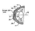
- FIG. 7is a cross-sectional side view of the eye of FIG. 6 with a contact lens placed on the external surface of the cornea to shape the ocular material.
- FIG. 8is a cross-sectional side view of a eye having a ring-shaped pocket formed in between layers of the cornea with a contact lens placed on the external surface of the cornea to shape the ocular material.
- FIG. 9is a front elevational view of a split ring ocular implant for use in the procedure shown in FIGS. 1-4 and 19 - 24 ;
- FIG. 10is a front elevational view of a two part ocular implant for use in the procedure shown in FIGS. 1-4 and 19 - 24 ;
- FIG. 11is a front elevational view of a three part ocular implant for use in the procedure shown in FIGS. 1-4 and 19 - 24 ;
- FIG. 12is a side elevational view in cross-section of the ocular implant of FIG. 9 , taken along lines 12 — 12 ;
- FIG. 13is a side elevational view in cross-section of the ocular implant of FIG. 10 , taken along lines 13 — 13 ;
- FIG. 14is a side elevational view in cross-section of an arcuate ocular implant for use in the procedure shown in FIGS. 1-4 and 19 - 24 ;
- FIG. 15is a side elevational view in cross-section of multiple ocular implants stacked on top of one another for use in the procedure shown in FIGS. 1-4 and 19 - 24 ;
- FIG. 16is a side elevational view in cross-section of an ocular implant having a non-uniform thickness for use in the procedure shown in FIGS. 1-4 and 19 - 24 ;
- FIG. 17is a front elevational view in cross-section of an ocular implant having four separate portions for use in the procedure shown in FIGS. 1-4 and 19 - 24 ;
- FIG. 18is a front elevational view in cross-section of an ocular implant having two portions of different thickness for use in the procedure shown in FIGS. 1-4 and 19 - 24 ;
- FIG. 19is a side elevational view in cross section similar to that shown in FIG. 1 with the incision in the pocket open;
- FIG. 20is a side elevational view in cross section similar to that shown in FIG. 19 , except that an annular or circular ocular implant has been introduced through the incision and between the internal surfaces; and
- FIG. 21is a side elevational view in cross section of a probe irradiating a portion of the ocular material to reduce the volume of the portion.
- FIG. 22is a side elevational view in cross section of a probe irradiating a portion of the ocular material to increase the volume of the portion.
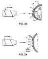
- FIG. 23is a side elevational view in cross section similar to that shown in FIG. 19 , except that a portion of the external surface of the cornea has been ablated by a laser.
- FIG. 24is a side elevational view in cross section of the cornea with a flap formed thereon and a laser ablating a portion of the ocular material.
- the refractive properties of eye 10can be altered by using laser 12 to separate an inner portion of the cornea into first internal corneal surface 14 and second internal corneal surface 16 , creating internal corneal pocket 18 in the cornea 20 and then placing ocular material or an implant 22 in the pocket 18 .
- the corneacan be shaped by using a second laser 24 to ablate a portion 26 of the surface 28 of the cornea 16 , or an external lens 29 to mold the ocular material.
- the refractive error in the eyeis measured using wavefront technology, as is known to one of ordinary skill in the art.
- wavefront technologysee U.S. Pat. No. 6,086,204 to Magnate, the entire contents of which is incorporated herein by reference.
- the refractive error measurementsare transmitted to a computerized lathe (not shown) or other lens-shaping machine, where the shape of ocular material is determined using the information from the wavefront device.
- the ocular material 22can be manufactured or shaped prior to the use of the wavefront technology and can be stored in a sterilized manner until that specific shape or size is needed.
- Ocular material or inlay 22has a first surface 21 and a second surface 23 and is porous to allow oxygen and nutrients to pass therethrough.
- Materials that are suitable for these purposesare preferably any polymer or hydrogel having about 50% water content; however, the water content can be any percentage desired.
- the ocular materialmay be formed from synthetic or organic material or a combination thereof.
- the ocular materialcan be collagen combined with or without cells; a mixture of synthetic material and corneal stromal cells; silicone or silicone mixed with collagen; mucopolysacharide; chodrotin sulfate; elsatins; methylmetacrylate; hydrogel; any transparent material, such as polyprolidine, polyvinylpylidine, polyethylenoxide, etc.; or any deformable and/or porous polymer, which can change its shape with radiation after implantation.
- the collagencan be a semiliquid, a gel, human or other animal, or it can de derivatized.
- ocular material 22is preferably about 0.5 mm to 5 mm wide.
- the thicknessis preferably about 5-2000 microns, and more preferably less than 200 microns.
- the inside edgecan be thinner or thicker than the outside edge; for example, the inside edge can have a thickness of about 1-100 microns, while the outside edge has a thickness of about 20-3000 microns.
- the ocular materialcan have any thickness or configuration that would allow it to elevate or move any portion of surface 14 relative to surface 16 .
- the thickness and position of ocular material 22generally defines the degree of correction.
- ocular material 22is a liquid or a gel that can be injected through the surface of the cornea using an injection device 25 , such as a needle, without making a large incision or opening in the surface of the lens, as seen in FIG. 6 .
- an injection device 25such as a needle
- the gelis confined to the corneal pocket 18 and will settle or move in the pocket in a predictable configuration or distribution. In other words, the gel will not flow through the layers of the cornea, but will rather stay inside the structure or confines of the pocket.
- the gelcan be inserted into a pocket that encompasses the entire front of the cornea, or extend past the cornea and Bowman layer to the sclera.
- the portion of the cornea above the pocketwould become loose.
- the injection of the gelwould allow lifting of the Bowman layer, lifting up the entire front surface of the cornea, allowing the eye to be reshaped as desired.
- the gelcan be injected or positioned into any size pocket desired and the pocket does not have to encompass the entire front of the cornea.
- the ocular materialdoes not necessarily need to be a gel in this process and may be a lens or any other desired material.
- the ocular material 22can include a silicone polymer which includes loose monomers that are responsive to light (both visible and invisible) within a certain wavelength range, such as the short ultraviolet wavelength range or the blue light wavelength range. In response to the light, the monomers become aggravated, and cross-linking occurs which increases the volume of the area of ocular material 22 or a portion of the ocular material, without substantially ablating the ocular material 22 , as well as fixing or hardening the ocular material.
- a silicone polymerwhich includes loose monomers that are responsive to light (both visible and invisible) within a certain wavelength range, such as the short ultraviolet wavelength range or the blue light wavelength range. In response to the light, the monomers become aggravated, and cross-linking occurs which increases the volume of the area of ocular material 22 or a portion of the ocular material, without substantially ablating the ocular material 22 , as well as fixing or hardening the ocular material.
- the ocular material 22can also include a polymer comprising a polycarbonate or acrylic material containing a dye or dyes manufactured, for example, by Centex Company.
- the dye or dyesabsorb light within a certain wavelength range, such as the infrared wavelength range, which causes slight melting or reduction of the material or a portion of the ocular material, as well as solidification. This melting or reduction results in a decrease or flattening of the irradiated area of the ocular material 22 , and thus reduces the volume of that area for purposes discussed in more detail below, without substantially ablating the ocular material 22 .
- Ocular material 22can also be a lens.
- a lensit can be any shape or sized desired.
- the lensis preferably substantially ring-shaped; but can be a circular or semicircular inlay.
- unitary lenses 22 a-chave a split 30 or have multiple portions that couple or fit together (FIGS. 9 - 11 ), lens 22 b is flat (FIG. 13 ), lens 22 d is arcuate (FIG. 14 ), and lens 22 a has tapered edges (FIG. 12 ).
- ocular material 22may have any combination of these properties.
- the portionscan couple together, simply abut one another, they can lay near each other, not necessarily touching each other or the lens portions can be separated from each other (FIGS. 17 and 18 ).
- Lens 22 bcan have multiple layers on top of each other (FIG. 15 ), or lens 22 c and 22 g can have two sides with different thickness (FIGS. 16 and 18 ), which would help to correct astigmatism.
- the lenspreferably allows light in the visible spectrum to pass therethrough and can have different or similar refractive properties to the refractive properties of the cornea, it can have pigmentation added thereto to change the color of the lens or it can be photochromatic.
- the lenscan have a substantially planar surface or an arcuate surface with no holes or apertures therein, as seen specifically in FIG. 5 .
- a laser 12is aimed at an internal portion of the cornea, adjacent the external surface of the cornea of the eye and fired.
- the laseris focused to create the pocket 18 in the first one-third of the cornea, and not in the back of the cornea.
- the pocketis preferably formed adjacent surface 28 or closer to surface 28 then to the interior or anterior chamber 11 of eye 10 .
- the pocket or pocketsmay extend beyond the Bowmans layer and the cornea, to create a large pocket, which would allow raising of the entire front portion of the cornea, as described above.
- the laserpreferably separates an internal area of the cornea offset from the main optical or visual axis 32 into first 14 and second 16 substantially ring-shaped internal surfaces to form the circular or ring-shaped corneal pocket 18 .
- First internal corneal surface 14faces in a posterior direction of cornea 20 and the second internal corneal surface 16 faces in an anterior direction of the cornea 20 .
- the distance from first internal corneal surface 14 to the exterior corneal surface 28is preferably a uniform thickness of about 10-250 microns, and more preferably about 80-100 microns, but can be any suitable thickness and does not necessarily need to be substantially uniform.
- a portion 34 of first and second surfaces 14 and 16preferably remains attached to each other by an area located at the main optical axis 32 .
- the lasercan form a pocket 18 of any suitable configuration, such as a pocket that is not attached at the main optical axis (FIG. 5 ), two substantially similar pockets 18 and 18 ′( FIG. 3 ) or four pockets 18 , 18 ′, 18 ′′ and 18 ′′′. (FIG. 4 ).
- the pocketsare separated by a portion 36 , which is an area where first and second surfaces 14 and 16 remain attached.
- the pocket or pocketsmay be any number, shape or size desired and they do not need to be circular or ring-shaped.
- Laser 12preferably is an ultrashort pulse laser, such as a femto, pico, or attosecond laser; but may be any light emitting device suitable for creating a pocket in the cornea as described above.
- the ultrashort pulse laseris positioned in front of the eye and is focused at the desired depth in the cornea and in the desired pocket configuration.
- Ultrashort pulse lasersare desired since they are high precision lasers that require less energy than conventional lasers to cut tissue and do not create “shock waves” that can damage surrounding structures. Cuts made by ultrashort pulse lasers can have very high surface quality with accuracy better than 10 microns, resulting in more precise cuts than those made with mechanical devices or other lasers. This type of accuracy results in less risks and complications than the procedures using other lasers or mechanical devices.
- an incision or opening 38is made in the surface 28 of the cornea to access pocket 18 or pockets 18 ′, 18 ′′ and 18 ′′′.
- the incision 38is made at the periphery of the pocket; however, it may be made anywhere desired that would allow access to the pocket 18 .
- multiple incisionscan be made that would allow access to different portions of pocket 18 or different pockets 18 ′, 18 ′′ and 18 ′′′.
- a carved instrument(not shown) can be inserted through the incision, which would dissect the pocket, if needed.
- a carved instrumentis generally used to extend the pocket 18 past the cornea or Bowmans layer to the sclera as described above. However, a large incision may not be necessary, as in the case where a gel is inserted using a needle, as described above.
- the ocular material 22is then inserted through the incision 28 or any other opening by opening the incision using any device known in the art, such as spatula or microforceps or any other device.
- a lenswhen used, it has at least two separate portions 40 and 42 ( FIG. 10 ) or has a split 30 ( FIG. 9 ) that allow the ocular material 22 to be positioned or introduced around or at least partially encircling the main optical axis 32 or portion 34 and in between the first and second internal surfaces 14 and 16 that define the pocket 18 .
- the first and second surfaces 14 and 16do not necessarily have to be attached at the main optical axis and in such a case, ocular material 22 is merely placed in pocket 18 .
- an external contact lens 29can be placed on the external surface of the cornea, which would allow the gel to be shaped or redistributed and, thus, the cornea to be reshaped in any manner desired.
- the proper size and shape of the contact lens 29is determined by the information received from the wavefront technology.
- Lens 29is preferably a temporary lens that would allow light if the visible spectrum to pass therethrough.
- the contact lens back surface 31forces the gel to distribute evenly until the topographically desired configuration is achieved.
- the opening 38may allow a small amount of gel to escape, if needed, to adjust the shape and size of the ocular material 22 .
- Wave front technologycan then be used to determine if the desired correction has been achieved, and if it has not the gel can be removed via an incision and the process repeated at a later time.
- the patient's eyecan be monitored or measured and a laser, probe 31 or other heating device can be used to reduce the overall thickness of the ocular material 22 , if necessary.
- the ocular material 22can initially be about 500 microns thick for ease of handling. Then, once the material 22 is positioned in the pocket 18 of the cornea, in the manner described above, the probe 40 (i.e., infrared light) can be directed to material 22 so as to reduce the overall thickness of material 22 , as desired.
- a 500 micron thick portion of the materialcan be reduced, for example, to about 100 microns or any suitable thickness by the heating device.
- the pulsed laser lightwhen the pulsed laser light is focused properly to a location within ocular material 22 , it can disrupt and thus shrink or melt ocular material 22 without the need of an absorbent dye.
- An example of such a laseris an ultrashort pulse laser, which emits nano-second pulses, pico-second pulses or femto-second pulses of laser light.
- laser light having a wavelength that is absorbed by water, or other types of energysuch as microwave radiation, radio frequency radiation, or thermal energy, can be used to cause shrinkage in the lens.
- an area of the materialis irradiated with energy L 1 , such as infrared light, laser light, microwave energy, radio frequency energy, or heat applied by a probe or laser 31 , to cause the area of the lens to shrink or, in other words, reduce in volume.
- energy L 1such as infrared light, laser light, microwave energy, radio frequency energy, or heat applied by a probe or laser 31 .
- This shrinkageoccurs without damage to the ocular material or other portion of the cornea 20 .
- the shrinkagecauses a change in the shape of the ocular material area, and thus changes the refractive power of the cornea 20 to further correct for the remaining vision disorder that was not fully corrected by the ocular material 22 .
- the ocular materialcan be irradiated directly through the cornea or through lens 29 .
- the patient's visioncan be monitored as the cornea 20 heals to determine if the size and shape of the ocular material 22 should be increased.
- the size or shape of the ocular materialcan be changed, and therefore the curvature of the cornea 20 can be changed without surgically opening the pocket 18 .
- the ocular material 22can include certain monomers which, when irradiated with light within a certain wavelength range (e.g., blue or ultraviolet light), become agitated and cross-link, which causes the ocular material 22 to increase in size at the area of the irradiation.
- an area of ocular material 22is irradiated by probe 33 or laser light L 2 , which passes through the layer 21 .
- the laser light L 2has a wavelength, such as long ultraviolet wavelength or light within the blue light spectrum, to aggravate the monomers, which causes a cross-linking effect that increases the volume of the ocular material 22 in the area being irradiated.
- this increase thicknesschanges the curvature of the cornea as shown, thus changing the refractive power of the cornea to a degree necessary to correct the remainder of the vision disorder that was not corrected by the insertion of the ocular material 22 .
- the ocular materialcan be irradiated directly through the cornea or through lens 29 .
- a chemicalcan be used to polymerize or solidify the ocular material, when the ocular material is a collegen solution.
- the chemicalis applied to the external surface of the cornea and passes through the cornea and into the pocket 18 , where it comes into contact with ocular material 22 and polymerizes the material.
- the chemical used to polymerize the collegen solutionis preferably about, 0.1 moler to 0.5 moler and more preferably about 0.2 moler to 0.4 moler of sodium persulphate diluted in a 0.02 moler phosphate buffer having a pH of about 8.0.
- the polymerizing chemical and the ocular materialmay be any suitable chemical and material known to one skilled in the art.
- the collegen solutioncan be depolymerized or returned to a gel or liquid state by applying glugaric anhydride in the same manner as described above for sodium persulphate.
- the depolymerization chemicalcan be any suitable chemical known in the art.
- a disodium phosphate of about 0.02 molar and pH of 8.5can be applied to the surface of the cornea.
- the refractive properties of the eyecan be remeasured using wavefront technology, and it can be determined if any refractive error remains in the eye.
- the refractive erroris less than ⁇ 2.0 diopters sphere or astigmatism.
- a second laser 44preferably an excimer laser
- a second laser 44can then be aimed and fired at the external surface of the cornea 24 , ablating a portion 26 of the cornea, as seen in FIG. 23 .
- the excimer lasercan be applied either through the corneal epithelium or the epithelium can be reopened initially using diluted alcohol (less than 20% alcohol) or a brush.
- the second laserpreferably ablates portion 26 of surface 22 that overlies the portion 34 attaches, but may ablate any portion desired.
- the patientcan undergo the second laser ablation either immediately after the insertion of the ocular implant or after a substantial time difference, such as days or weeks later, and any step or portion of the above procedure may be repeated to decrease the refractive error in the eye.
- a flap 42can be formed in the surface of the cornea of the eye, which would expose the ocular material 22 when removed or folded away.
- the ocular materialcan be irradiated and a portion 44 or the material 22 ablated by an excimer laser 46 and wavefront technology, as described above.
- this techniqueis used on the pocket having no portion attached in the center, but may be used with any type of pocket, including the ring-shaped pocket.
- topical agentssuch as an anti-inflammatory, antibiotics and/or an antiprolifrative agent, such as mitomycin or thiotepa
- topical agentssuch as an anti-inflammatory, antibiotics and/or an antiprolifrative agent, such as mitomycin or thiotepa
- the mitomycin concentrationis preferably about 0.005-0.05% and more preferably about 0.02%.
- a short-term bandage contact lensmay also be used to protect the cornea.
Landscapes
- Health & Medical Sciences (AREA)
- Ophthalmology & Optometry (AREA)
- Animal Behavior & Ethology (AREA)
- General Health & Medical Sciences (AREA)
- Veterinary Medicine (AREA)
- Engineering & Computer Science (AREA)
- Biomedical Technology (AREA)
- Heart & Thoracic Surgery (AREA)
- Vascular Medicine (AREA)
- Life Sciences & Earth Sciences (AREA)
- Public Health (AREA)
- Physics & Mathematics (AREA)
- Optics & Photonics (AREA)
- Nuclear Medicine, Radiotherapy & Molecular Imaging (AREA)
- Surgery (AREA)
- Oral & Maxillofacial Surgery (AREA)
- Cardiology (AREA)
- Transplantation (AREA)
- Laser Surgery Devices (AREA)
- Prostheses (AREA)
Abstract
Description
Claims (26)
Priority Applications (5)
| Application Number | Priority Date | Filing Date | Title |
|---|---|---|---|
| US09/815,277US6989008B2 (en) | 2001-03-23 | 2001-03-23 | Adjustable ablatable inlay |
| US09/843,141US6551307B2 (en) | 2001-03-23 | 2001-04-27 | Vision correction using intrastromal pocket and flap |
| EP02723540AEP1381326A4 (en) | 2001-03-23 | 2002-03-22 | Adjustable ablatable inlay |
| PCT/US2002/008681WO2002076320A1 (en) | 2001-03-23 | 2002-03-22 | Adjustable ablatable inlay |
| US12/205,820US20090069817A1 (en) | 1995-10-20 | 2008-09-05 | Intrastromal corneal modification |
Applications Claiming Priority (1)
| Application Number | Priority Date | Filing Date | Title |
|---|---|---|---|
| US09/815,277US6989008B2 (en) | 2001-03-23 | 2001-03-23 | Adjustable ablatable inlay |
Related Parent Applications (1)
| Application Number | Title | Priority Date | Filing Date |
|---|---|---|---|
| US09/758,263Continuation-In-PartUS20010027314A1 (en) | 1995-10-20 | 2001-01-12 | Intrastromal corneal modification via laser |
Related Child Applications (2)
| Application Number | Title | Priority Date | Filing Date |
|---|---|---|---|
| US09/843,141Continuation-In-PartUS6551307B2 (en) | 1995-10-20 | 2001-04-27 | Vision correction using intrastromal pocket and flap |
| US26992605AContinuation-In-Part | 1995-10-20 | 2005-11-08 |
Publications (2)
| Publication Number | Publication Date |
|---|---|
| US20020138069A1 US20020138069A1 (en) | 2002-09-26 |
| US6989008B2true US6989008B2 (en) | 2006-01-24 |
Family
ID=25217348
Family Applications (1)
| Application Number | Title | Priority Date | Filing Date |
|---|---|---|---|
| US09/815,277Expired - Fee RelatedUS6989008B2 (en) | 1995-10-20 | 2001-03-23 | Adjustable ablatable inlay |
Country Status (1)
| Country | Link |
|---|---|
| US (1) | US6989008B2 (en) |
Cited By (24)
| Publication number | Priority date | Publication date | Assignee | Title |
|---|---|---|---|---|
| US7220224B1 (en)* | 2003-03-07 | 2007-05-22 | Minu, Llc | Retinal translocation and fixation using adhesive material |
| US20070219542A1 (en)* | 2006-03-15 | 2007-09-20 | Toru Yahagi | Surgical procedure and instrumentation for intrastromal implants of lens or strengthening materials |
| US20070291224A1 (en)* | 2006-06-15 | 2007-12-20 | Lai Shui T | High Visual Acuity Contact Lenses |
| US20080039825A1 (en)* | 2006-07-26 | 2008-02-14 | Lai Shui T | Intrastromal Surgery Correcting Low Order and High Order Aberrations of the Eye |
| US20080058777A1 (en)* | 2006-09-05 | 2008-03-06 | Intralase Corp. | System and method for resecting corneal tissue using non-continuous initial incisions |
| US20080212024A1 (en)* | 2006-09-18 | 2008-09-04 | Lai Shui T | Customized contact lenses for reducing aberrations of the eye |
| US20090069817A1 (en)* | 1995-10-20 | 2009-03-12 | Acufocus, Inc. | Intrastromal corneal modification |
| US7726811B2 (en) | 2006-02-14 | 2010-06-01 | Lai Shui T | Subjective wavefront refraction using continuously adjustable wave plates of Zernike function |
| US20110040376A1 (en)* | 2009-08-13 | 2011-02-17 | Acufocus, Inc. | Masked intraocular implants and lenses |
| US7959284B2 (en) | 2006-07-25 | 2011-06-14 | Lai Shui T | Method of making high precision optics having a wavefront profile |
| WO2012035403A1 (en)* | 2010-09-13 | 2012-03-22 | Singapore Health Services Pte Ltd | Method for performing a reversible refractive procedure |
| US8752958B2 (en) | 1999-03-01 | 2014-06-17 | Boston Innovative Optics, Inc. | System and method for increasing the depth of focus of the human eye |
| US8864824B2 (en) | 2003-06-17 | 2014-10-21 | Acufocus, Inc. | Method and apparatus for aligning a mask with the visual axis of an eye |
| US9138142B2 (en) | 2003-05-28 | 2015-09-22 | Acufocus, Inc. | Masked intraocular devices |
| US9204962B2 (en) | 2013-03-13 | 2015-12-08 | Acufocus, Inc. | In situ adjustable optical mask |
| US9427311B2 (en) | 2009-08-13 | 2016-08-30 | Acufocus, Inc. | Corneal inlay with nutrient transport structures |
| US9427922B2 (en) | 2013-03-14 | 2016-08-30 | Acufocus, Inc. | Process for manufacturing an intraocular lens with an embedded mask |
| US9545303B2 (en) | 2011-12-02 | 2017-01-17 | Acufocus, Inc. | Ocular mask having selective spectral transmission |
| US9943403B2 (en) | 2014-11-19 | 2018-04-17 | Acufocus, Inc. | Fracturable mask for treating presbyopia |
| US10004593B2 (en) | 2009-08-13 | 2018-06-26 | Acufocus, Inc. | Intraocular lens with elastic mask |
| US10687935B2 (en) | 2015-10-05 | 2020-06-23 | Acufocus, Inc. | Methods of molding intraocular lenses |
| US11364110B2 (en) | 2018-05-09 | 2022-06-21 | Acufocus, Inc. | Intraocular implant with removable optic |
| US11464625B2 (en) | 2015-11-24 | 2022-10-11 | Acufocus, Inc. | Toric small aperture intraocular lens with extended depth of focus |
| EP4218670A4 (en)* | 2020-09-25 | 2023-11-22 | Paulo Ferrara De Almeida Cunha | Double-segment intrastromal device for correcting severe ametropia |
Families Citing this family (22)
| Publication number | Priority date | Publication date | Assignee | Title |
|---|---|---|---|---|
| US6275512B1 (en)* | 1998-11-25 | 2001-08-14 | Imra America, Inc. | Mode-locked multimode fiber laser pulse source |
| CA2421948C (en) | 2000-09-12 | 2009-12-22 | Anamed, Inc. | System for packaging and handling an implant and method of use |
| US8668735B2 (en) | 2000-09-12 | 2014-03-11 | Revision Optics, Inc. | Corneal implant storage and delivery devices |
| US7156859B2 (en) | 2001-07-23 | 2007-01-02 | Fos Holding S.A. | Device for separating the epithelium layer from the surface of the cornea of an eye |
| EP1549255A4 (en) | 2002-09-13 | 2007-12-19 | Coopervision Inc | Devices and methods for improving vision |
| US10835371B2 (en) | 2004-04-30 | 2020-11-17 | Rvo 2.0, Inc. | Small diameter corneal inlay methods |
| JP2007537829A (en) | 2004-05-20 | 2007-12-27 | クーパーヴィジョン インコーポレイテッド | Corneal onlay and wavefront aberration correction for visual enhancement |
| WO2006019893A2 (en)* | 2004-07-15 | 2006-02-23 | Coopervision, Inc. | Intrastromal devices and method for improving vision |
| US10555805B2 (en) | 2006-02-24 | 2020-02-11 | Rvo 2.0, Inc. | Anterior corneal shapes and methods of providing the shapes |
| US7883520B2 (en) | 2006-04-10 | 2011-02-08 | Forsight Labs, Llc | Corneal epithelial pocket formation systems, components and methods |
| US9549848B2 (en) | 2007-03-28 | 2017-01-24 | Revision Optics, Inc. | Corneal implant inserters and methods of use |
| US8162953B2 (en) | 2007-03-28 | 2012-04-24 | Revision Optics, Inc. | Insertion system for corneal implants |
| US9271828B2 (en) | 2007-03-28 | 2016-03-01 | Revision Optics, Inc. | Corneal implant retaining devices and methods of use |
| WO2009070438A1 (en)* | 2007-11-30 | 2009-06-04 | Bausch & Lomb Incorporated | Optical material and method for modifying the refractive index |
| US9539143B2 (en) | 2008-04-04 | 2017-01-10 | Revision Optics, Inc. | Methods of correcting vision |
| JP2011516180A (en) | 2008-04-04 | 2011-05-26 | レヴィジオン・オプティックス・インコーポレーテッド | Corneal inlay design and method for correcting vision |
| US8469948B2 (en)* | 2010-08-23 | 2013-06-25 | Revision Optics, Inc. | Methods and devices for forming corneal channels |
| KR20140007913A (en)* | 2011-02-15 | 2014-01-20 | 웨이브라이트 게엠베하 | Apparatus for assistance in the implantation of a corneal prosthesis in a human eye, and method for executing such an implantation |
| WO2013059813A1 (en) | 2011-10-21 | 2013-04-25 | Revision Optics, Inc. | Corneal implant storage and delivery devices |
| KR102007990B1 (en)* | 2013-02-27 | 2019-08-06 | 노바르티스 아게 | Laser apparatus and method for laser processing a target material |
| AU2015385773A1 (en) | 2015-03-12 | 2017-10-05 | Revision Optics, Inc. | Methods of correcting vision |
| BR112018076401A2 (en) | 2016-06-23 | 2019-04-09 | Medicem Inst S R O | covalently cross-linked hydrogel, implants using it, lightweight, bioanalytical, adjustable hydrogel intraocular lenses and methods for making such adjustments |
Citations (38)
| Publication number | Priority date | Publication date | Assignee | Title |
|---|---|---|---|---|
| US3776230A (en)* | 1973-04-18 | 1973-12-04 | C Neefe | Method of rapidly reshaping the cornea to eliminate refractive errors |
| US3982541A (en) | 1974-07-29 | 1976-09-28 | Esperance Jr Francis A L | Eye surgical instrument |
| US4298004A (en) | 1979-02-27 | 1981-11-03 | Schachar Ronald A | Surgical method for altering the curvature of the cornea of rabbits |
| US4452235A (en) | 1982-01-04 | 1984-06-05 | Reynolds Alvin E | Method for corneal curvature adjustment |
| US4655774A (en) | 1986-01-03 | 1987-04-07 | Choyce D Peter | Intra-corneal implant for correction of aniridia |
| US4665913A (en) | 1983-11-17 | 1987-05-19 | Lri L.P. | Method for ophthalmological surgery |
| US4669466A (en) | 1985-01-16 | 1987-06-02 | Lri L.P. | Method and apparatus for analysis and correction of abnormal refractive errors of the eye |
| US4676790A (en) | 1985-09-25 | 1987-06-30 | Kern Seymour P | Method of manufacture and implantation of corneal inlays |
| US4718418A (en) | 1983-11-17 | 1988-01-12 | Lri L.P. | Apparatus for ophthalmological surgery |
| US4729372A (en) | 1983-11-17 | 1988-03-08 | Lri L.P. | Apparatus for performing ophthalmic laser surgery |
| US4744360A (en) | 1986-12-18 | 1988-05-17 | Bath Patricia E | Apparatus for ablating and removing cataract lenses |
| US4807623A (en) | 1986-05-30 | 1989-02-28 | David M. Lieberman | Device for simultaneously forming two incisions along a path on an eye |
| US4840175A (en) | 1986-12-24 | 1989-06-20 | Peyman Gholam A | Method for modifying corneal curvature |
| US4903695A (en) | 1988-11-30 | 1990-02-27 | Lri L.P. | Method and apparatus for performing a keratomileusis or the like operation |
| US4907586A (en)* | 1988-03-31 | 1990-03-13 | Intelligent Surgical Lasers | Method for reshaping the eye |
| US4961744A (en) | 1982-01-04 | 1990-10-09 | Keravision, Inc. | Holder for inserting corneal curvature adjustable ring |
| US4994058A (en) | 1986-03-19 | 1991-02-19 | Summit Technology, Inc. | Surface shaping using lasers |
| US5063942A (en) | 1989-12-14 | 1991-11-12 | Corneal Contouring, Inc. | Method for surgically re-profiling the cornea |
| US5090955A (en)* | 1990-07-12 | 1992-02-25 | University Of Miami | Gel injection adjustable keratoplasty |
| US5196027A (en) | 1990-05-02 | 1993-03-23 | Thompson Keith P | Apparatus and process for application and adjustable reprofiling of synthetic lenticules for vision correction |
| US5196026A (en) | 1991-09-16 | 1993-03-23 | Chiron Ophthalmics, Inc. | Method of implanting corneal inlay lenses smaller than the optic zone |
| US5215104A (en) | 1988-08-16 | 1993-06-01 | Steinert Roger F | Method for corneal modification |
| US5300118A (en) | 1992-09-21 | 1994-04-05 | Keravision | Adjustable devices for corneal curvature adjustment |
| US5318044A (en) | 1989-12-14 | 1994-06-07 | Corneal Contouring, Inc. | Method and apparatus for re-profiling the cornea to correct for hyperopia |
| US5318047A (en) | 1992-01-14 | 1994-06-07 | Keravision Inc. | Method for corneal curvature variation |
| US5323788A (en) | 1992-09-21 | 1994-06-28 | Keravision | Overlapping split ring device for corneal curvature adjustment |
| US5368604A (en) | 1989-12-14 | 1994-11-29 | Corneal Contouring Inc. | Method and apparatus for surgically profiling the cornea using vacuum |
| US5391201A (en) | 1992-10-02 | 1995-02-21 | Chiron Intraoptics, Inc. | Method of using a corneal ring inlay |
| US5403335A (en) | 1992-04-10 | 1995-04-04 | Keravision, Inc. | Corneal vacuum centering guide and dissector |
| US5405384A (en) | 1992-09-03 | 1995-04-11 | Keravision, Inc. | Astigmatic correcting intrastromal corneal ring |
| US5720894A (en) | 1996-01-11 | 1998-02-24 | The Regents Of The University Of California | Ultrashort pulse high repetition rate laser system for biological tissue processing |
| US5722971A (en) | 1995-10-20 | 1998-03-03 | Peyman; Gholam A. | Intrastromal corneal modification |
| US5919185A (en) | 1997-04-25 | 1999-07-06 | Peyman; Gholam A. | Universal implant blank for modifying corneal curvature and methods of modifying corneal curvature therewith |
| US5964776A (en) | 1997-09-24 | 1999-10-12 | Peyman; Gholam A. | Internal keratome apparatus and method for using the same to form a pocket/flap between layers of a live cornea |
| US6086204A (en) | 1999-09-20 | 2000-07-11 | Magnante; Peter C. | Methods and devices to design and fabricate surfaces on contact lenses and on corneal tissue that correct the eye's optical aberrations |
| US6102946A (en) | 1998-12-23 | 2000-08-15 | Anamed, Inc. | Corneal implant and method of manufacture |
| US6203538B1 (en) | 1995-11-03 | 2001-03-20 | Gholam A. Peyman | Intrastromal corneal modification |
| US6210401B1 (en) | 1991-08-02 | 2001-04-03 | Shui T. Lai | Method of, and apparatus for, surgery of the cornea |
- 2001
- 2001-03-23USUS09/815,277patent/US6989008B2/ennot_activeExpired - Fee Related
Patent Citations (40)
| Publication number | Priority date | Publication date | Assignee | Title |
|---|---|---|---|---|
| US3776230A (en)* | 1973-04-18 | 1973-12-04 | C Neefe | Method of rapidly reshaping the cornea to eliminate refractive errors |
| US3982541A (en) | 1974-07-29 | 1976-09-28 | Esperance Jr Francis A L | Eye surgical instrument |
| US4298004A (en) | 1979-02-27 | 1981-11-03 | Schachar Ronald A | Surgical method for altering the curvature of the cornea of rabbits |
| US4961744A (en) | 1982-01-04 | 1990-10-09 | Keravision, Inc. | Holder for inserting corneal curvature adjustable ring |
| US4452235A (en) | 1982-01-04 | 1984-06-05 | Reynolds Alvin E | Method for corneal curvature adjustment |
| US4729372A (en) | 1983-11-17 | 1988-03-08 | Lri L.P. | Apparatus for performing ophthalmic laser surgery |
| US4718418A (en) | 1983-11-17 | 1988-01-12 | Lri L.P. | Apparatus for ophthalmological surgery |
| US4665913A (en) | 1983-11-17 | 1987-05-19 | Lri L.P. | Method for ophthalmological surgery |
| US4669466A (en) | 1985-01-16 | 1987-06-02 | Lri L.P. | Method and apparatus for analysis and correction of abnormal refractive errors of the eye |
| US4676790A (en) | 1985-09-25 | 1987-06-30 | Kern Seymour P | Method of manufacture and implantation of corneal inlays |
| US4655774A (en) | 1986-01-03 | 1987-04-07 | Choyce D Peter | Intra-corneal implant for correction of aniridia |
| US4994058A (en) | 1986-03-19 | 1991-02-19 | Summit Technology, Inc. | Surface shaping using lasers |
| US4807623A (en) | 1986-05-30 | 1989-02-28 | David M. Lieberman | Device for simultaneously forming two incisions along a path on an eye |
| US4744360A (en) | 1986-12-18 | 1988-05-17 | Bath Patricia E | Apparatus for ablating and removing cataract lenses |
| US4840175A (en) | 1986-12-24 | 1989-06-20 | Peyman Gholam A | Method for modifying corneal curvature |
| US4907586A (en)* | 1988-03-31 | 1990-03-13 | Intelligent Surgical Lasers | Method for reshaping the eye |
| US5215104A (en) | 1988-08-16 | 1993-06-01 | Steinert Roger F | Method for corneal modification |
| US4903695A (en) | 1988-11-30 | 1990-02-27 | Lri L.P. | Method and apparatus for performing a keratomileusis or the like operation |
| US4903695C1 (en) | 1988-11-30 | 2001-09-11 | Lri L P | Method and apparatus for performing a keratomileusis or the like operation |
| US5063942A (en) | 1989-12-14 | 1991-11-12 | Corneal Contouring, Inc. | Method for surgically re-profiling the cornea |
| US5368604A (en) | 1989-12-14 | 1994-11-29 | Corneal Contouring Inc. | Method and apparatus for surgically profiling the cornea using vacuum |
| US5318044A (en) | 1989-12-14 | 1994-06-07 | Corneal Contouring, Inc. | Method and apparatus for re-profiling the cornea to correct for hyperopia |
| US5196027A (en) | 1990-05-02 | 1993-03-23 | Thompson Keith P | Apparatus and process for application and adjustable reprofiling of synthetic lenticules for vision correction |
| US5090955A (en)* | 1990-07-12 | 1992-02-25 | University Of Miami | Gel injection adjustable keratoplasty |
| US6210401B1 (en) | 1991-08-02 | 2001-04-03 | Shui T. Lai | Method of, and apparatus for, surgery of the cornea |
| US5196026A (en) | 1991-09-16 | 1993-03-23 | Chiron Ophthalmics, Inc. | Method of implanting corneal inlay lenses smaller than the optic zone |
| US5336261A (en) | 1991-09-16 | 1994-08-09 | Chiron Intraoptics, Inc. | Corneal inlay lenses |
| US5318047A (en) | 1992-01-14 | 1994-06-07 | Keravision Inc. | Method for corneal curvature variation |
| US5403335A (en) | 1992-04-10 | 1995-04-04 | Keravision, Inc. | Corneal vacuum centering guide and dissector |
| US5405384A (en) | 1992-09-03 | 1995-04-11 | Keravision, Inc. | Astigmatic correcting intrastromal corneal ring |
| US5323788A (en) | 1992-09-21 | 1994-06-28 | Keravision | Overlapping split ring device for corneal curvature adjustment |
| US5300118A (en) | 1992-09-21 | 1994-04-05 | Keravision | Adjustable devices for corneal curvature adjustment |
| US5391201A (en) | 1992-10-02 | 1995-02-21 | Chiron Intraoptics, Inc. | Method of using a corneal ring inlay |
| US5722971A (en) | 1995-10-20 | 1998-03-03 | Peyman; Gholam A. | Intrastromal corneal modification |
| US6203538B1 (en) | 1995-11-03 | 2001-03-20 | Gholam A. Peyman | Intrastromal corneal modification |
| US5720894A (en) | 1996-01-11 | 1998-02-24 | The Regents Of The University Of California | Ultrashort pulse high repetition rate laser system for biological tissue processing |
| US5919185A (en) | 1997-04-25 | 1999-07-06 | Peyman; Gholam A. | Universal implant blank for modifying corneal curvature and methods of modifying corneal curvature therewith |
| US5964776A (en) | 1997-09-24 | 1999-10-12 | Peyman; Gholam A. | Internal keratome apparatus and method for using the same to form a pocket/flap between layers of a live cornea |
| US6102946A (en) | 1998-12-23 | 2000-08-15 | Anamed, Inc. | Corneal implant and method of manufacture |
| US6086204A (en) | 1999-09-20 | 2000-07-11 | Magnante; Peter C. | Methods and devices to design and fabricate surfaces on contact lenses and on corneal tissue that correct the eye's optical aberrations |
Non-Patent Citations (13)
| Title |
|---|
| "Corneal Surgery" by L. Girard, The C.V. Mosby Publishing Company, London 1981 pp. 107-141. |
| "Epikeratophakia: Techniques, Complications and Clinical Results" by Werblin, Ophthalmology, prior to 1996, pp. 45-58. |
| "Keratomileusis and Keratophakia in the Surgical Correction of Aphakia" by Barraquer, Cataract Surgery and Special Techniques, prior to 1996, pp. 270-289. |
| "Lamellar Corneal Stromectomy for the Operative Treatment of Myopia" by Tadeusz Krwawicz, Notes, Cases, Instruments, received in PTO-Sep. 1986, pp. 828-833. |
| "New U-developed laser performs high-precision corneal surgery", by Sally Pobojewski, News and Information Services, The University Record, Jul. 16, 1997. |
| "Refractive Keratoplasty: Acute Morphologic Features," by Baumgartner et al., the CLAO Journal-Apr., 1985, vol. II, No. 2 pp. 163-169. |
| Binder et al.; "Hydrogel keratophakia in non-human primates", Current Eye Research, vol. 1, No. 9, 1981/1982, pp. 535-542. |
| Cao et al.; "Comparative study of the use of poly(glycolic acid), calcium alginate and pluronics in the engineering of autologous porcine cartilage", Polymers for Tissue Engineering, pp. 315-327, VSP 1998. |
| Griffith et al.; "Functional Human Corneal Equivalents Constructed from Cell Lines", SCIENCE, vol. 286, Dec. 10, 1999 pp. 2169-2172. |
| Ijima et al.; "Formation of a spherical multicellular aggregate (spheroid) of animal cells in the pores of polyurethane foam as a cell culture substratum and its application to a hybrid artificial liver", Polymers for Tissue Engineering, pp. 273-286, VSP 1998. |
| Karin R. Sletten, MD et al.; Experimental Science, "An In Vivo Model of Femtosecond Laser Intrastromal Refractive Surgery", Ophthalmic Surgery and Lasers, Nov./Dec. 1999, vol. 30, No. 9, pp. 742-749. |
| Swinger et al.; "Keratophakia and Keratomileusis-Clinical Results", American Academy of Ophthalmology, Aug. 1981, vol. 88, No. 8, pp. 709-715. |
| Yamauchi et al.; "Cultivation of fibroblast cells on keratin-coated substrata", Polymers for Tissue Engineering, pp. 329-340, VS 1998. |
Cited By (52)
| Publication number | Priority date | Publication date | Assignee | Title |
|---|---|---|---|---|
| US20090069817A1 (en)* | 1995-10-20 | 2009-03-12 | Acufocus, Inc. | Intrastromal corneal modification |
| US8752958B2 (en) | 1999-03-01 | 2014-06-17 | Boston Innovative Optics, Inc. | System and method for increasing the depth of focus of the human eye |
| US7220224B1 (en)* | 2003-03-07 | 2007-05-22 | Minu, Llc | Retinal translocation and fixation using adhesive material |
| US9138142B2 (en) | 2003-05-28 | 2015-09-22 | Acufocus, Inc. | Masked intraocular devices |
| US10869752B2 (en) | 2003-05-28 | 2020-12-22 | Acufocus, Inc. | Mask for increasing depth of focus |
| US8864824B2 (en) | 2003-06-17 | 2014-10-21 | Acufocus, Inc. | Method and apparatus for aligning a mask with the visual axis of an eye |
| US9320426B2 (en) | 2006-02-14 | 2016-04-26 | Shui T. Lai | Subjective wavefront refraction using continuously adjustable wave plates of zernike function |
| US10383512B2 (en) | 2006-02-14 | 2019-08-20 | Shui T. Lai | Subjective wavefront refraction using continuously adjustable wave plates of Zernike function |
| US7726811B2 (en) | 2006-02-14 | 2010-06-01 | Lai Shui T | Subjective wavefront refraction using continuously adjustable wave plates of Zernike function |
| US20070219542A1 (en)* | 2006-03-15 | 2007-09-20 | Toru Yahagi | Surgical procedure and instrumentation for intrastromal implants of lens or strengthening materials |
| US7748844B2 (en) | 2006-06-15 | 2010-07-06 | Lai Shui T | High visual acuity contact lenses |
| US20070291224A1 (en)* | 2006-06-15 | 2007-12-20 | Lai Shui T | High Visual Acuity Contact Lenses |
| US7959284B2 (en) | 2006-07-25 | 2011-06-14 | Lai Shui T | Method of making high precision optics having a wavefront profile |
| US8262220B2 (en) | 2006-07-25 | 2012-09-11 | Lai Shui T | Method of making high precision optics having a wavefront profile |
| US10874298B2 (en) | 2006-07-26 | 2020-12-29 | Shui T. Lai | Intrastromal surgery correcting low order and high order aberrations of the eye |
| US9955867B2 (en)* | 2006-07-26 | 2018-05-01 | Shui T. Lai | Intrastromal surgery correcting low order and high order aberrations of the eye |
| WO2008014419A3 (en)* | 2006-07-26 | 2008-11-06 | Shui T Lai | Intrastromal surgery correcting low order and high order aberrations of the eye |
| US20080039825A1 (en)* | 2006-07-26 | 2008-02-14 | Lai Shui T | Intrastromal Surgery Correcting Low Order and High Order Aberrations of the Eye |
| US7887532B2 (en)* | 2006-09-05 | 2011-02-15 | Amo Development, Llc. | System and method for resecting corneal tissue using non-continuous initial incisions |
| US20080058777A1 (en)* | 2006-09-05 | 2008-03-06 | Intralase Corp. | System and method for resecting corneal tissue using non-continuous initial incisions |
| US20080212024A1 (en)* | 2006-09-18 | 2008-09-04 | Lai Shui T | Customized contact lenses for reducing aberrations of the eye |
| US9005281B2 (en) | 2009-08-13 | 2015-04-14 | Acufocus, Inc. | Masked intraocular implants and lenses |
| US10004593B2 (en) | 2009-08-13 | 2018-06-26 | Acufocus, Inc. | Intraocular lens with elastic mask |
| US11311371B2 (en) | 2009-08-13 | 2022-04-26 | Acufocus, Inc. | Intraocular lens with elastic mask |
| US9492272B2 (en) | 2009-08-13 | 2016-11-15 | Acufocus, Inc. | Masked intraocular implants and lenses |
| US10449036B2 (en) | 2009-08-13 | 2019-10-22 | Acufocus, Inc. | Masked intraocular implants and lenses |
| US10548717B2 (en) | 2009-08-13 | 2020-02-04 | Acufocus, Inc. | Intraocular lens with elastic mask |
| US9427311B2 (en) | 2009-08-13 | 2016-08-30 | Acufocus, Inc. | Corneal inlay with nutrient transport structures |
| US20110040376A1 (en)* | 2009-08-13 | 2011-02-17 | Acufocus, Inc. | Masked intraocular implants and lenses |
| US11357617B2 (en) | 2009-08-13 | 2022-06-14 | Acufocus, Inc. | Method of implanting and forming masked intraocular implants and lenses |
| WO2012035403A1 (en)* | 2010-09-13 | 2012-03-22 | Singapore Health Services Pte Ltd | Method for performing a reversible refractive procedure |
| AU2011303580B2 (en)* | 2010-09-13 | 2016-03-10 | Singapore Health Services Pte Ltd | Method for performing a reversible refractive procedure |
| US9848979B2 (en) | 2011-12-02 | 2017-12-26 | Acufocus, Inc. | Ocular mask having selective spectral transmission |
| US10765508B2 (en) | 2011-12-02 | 2020-09-08 | AcFocus, Inc. | Ocular mask having selective spectral transmission |
| US10342656B2 (en) | 2011-12-02 | 2019-07-09 | Acufocus, Inc. | Ocular mask having selective spectral transmission |
| US9545303B2 (en) | 2011-12-02 | 2017-01-17 | Acufocus, Inc. | Ocular mask having selective spectral transmission |
| US9603704B2 (en) | 2013-03-13 | 2017-03-28 | Acufocus, Inc. | In situ adjustable optical mask |
| US10350058B2 (en) | 2013-03-13 | 2019-07-16 | Acufocus, Inc. | In situ adjustable optical mask |
| US11771552B2 (en) | 2013-03-13 | 2023-10-03 | Acufocus, Inc. | In situ adjustable optical mask |
| US9204962B2 (en) | 2013-03-13 | 2015-12-08 | Acufocus, Inc. | In situ adjustable optical mask |
| US10939995B2 (en) | 2013-03-13 | 2021-03-09 | Acufocus, Inc. | In situ adjustable optical mask |
| US9573328B2 (en) | 2013-03-14 | 2017-02-21 | Acufocus, Inc. | Process for manufacturing an intraocular lens with an embedded mask |
| US9844919B2 (en) | 2013-03-14 | 2017-12-19 | Acufocus, Inc. | Process for manufacturing an intraocular lens with an embedded mask |
| US9427922B2 (en) | 2013-03-14 | 2016-08-30 | Acufocus, Inc. | Process for manufacturing an intraocular lens with an embedded mask |
| US10583619B2 (en) | 2013-03-14 | 2020-03-10 | Acufocus, Inc. | Process for manufacturing an intraocular lens with an embedded mask |
| US10183453B2 (en) | 2013-03-14 | 2019-01-22 | Acufocus, Inc. | Process for manufacturing an intraocular lens with an embedded mask |
| US9943403B2 (en) | 2014-11-19 | 2018-04-17 | Acufocus, Inc. | Fracturable mask for treating presbyopia |
| US10687935B2 (en) | 2015-10-05 | 2020-06-23 | Acufocus, Inc. | Methods of molding intraocular lenses |
| US11690707B2 (en) | 2015-10-05 | 2023-07-04 | Acufocus, Inc. | Methods of molding intraocular lenses |
| US11464625B2 (en) | 2015-11-24 | 2022-10-11 | Acufocus, Inc. | Toric small aperture intraocular lens with extended depth of focus |
| US11364110B2 (en) | 2018-05-09 | 2022-06-21 | Acufocus, Inc. | Intraocular implant with removable optic |
| EP4218670A4 (en)* | 2020-09-25 | 2023-11-22 | Paulo Ferrara De Almeida Cunha | Double-segment intrastromal device for correcting severe ametropia |
Also Published As
| Publication number | Publication date |
|---|---|
| US20020138069A1 (en) | 2002-09-26 |
Similar Documents
| Publication | Publication Date | Title |
|---|---|---|
| US6989008B2 (en) | Adjustable ablatable inlay | |
| US6551307B2 (en) | Vision correction using intrastromal pocket and flap | |
| EP1534188B1 (en) | Optical Corneal Implant | |
| US20050143717A1 (en) | Method of treatment of refractive errors using subepithelial or intrastromal corneal inlay with bonding coating | |
| KR100600210B1 (en) | Universal transplant blank for corneal refractive index correction and corneal refractive index correction method | |
| US7001374B2 (en) | Adjustable inlay with multizone polymerization | |
| US6436092B1 (en) | Adjustable universal implant blank for modifying corneal curvature and methods of modifying corneal curvature therewith | |
| EP1159033B1 (en) | A universal implant blank for midifying corneal curvature | |
| US9681942B2 (en) | Method for prevention of rejection and sever encapsulation of a supportive or functioning implant | |
| US20050182488A1 (en) | Implant and method for altering the refractive properties of the eye | |
| JP2006502805A (en) | Adjustable inlay using multi-zone polymerization | |
| HK1151451A (en) | Optical corneal implant |
Legal Events
| Date | Code | Title | Description |
|---|---|---|---|
| AS | Assignment | Owner name:MINU, L.L.C., NORTH CAROLINA Free format text:ASSIGNMENT OF ASSIGNORS INTEREST;ASSIGNOR:PEYMAN, GHOLAM A.;REEL/FRAME:013886/0422 Effective date:20030224 | |
| AS | Assignment | Owner name:ACUFOCUS, INC., CALIFORNIA Free format text:ASSIGNMENT OF ASSIGNORS INTEREST;ASSIGNOR:AOS, INC.;REEL/FRAME:020056/0043 Effective date:20070924 | |
| FEPP | Fee payment procedure | Free format text:PAYOR NUMBER ASSIGNED (ORIGINAL EVENT CODE: ASPN); ENTITY STATUS OF PATENT OWNER: SMALL ENTITY | |
| FPAY | Fee payment | Year of fee payment:4 | |
| AS | Assignment | Owner name:COWEN HEALTHCARE ROYALTY PARTNERS II, L.P., CONNEC Free format text:SECURITY AGREEMENT;ASSIGNOR:ACUFOCUS, INC.;REEL/FRAME:027195/0379 Effective date:20111107 | |
| REMI | Maintenance fee reminder mailed | ||
| LAPS | Lapse for failure to pay maintenance fees | ||
| STCH | Information on status: patent discontinuation | Free format text:PATENT EXPIRED DUE TO NONPAYMENT OF MAINTENANCE FEES UNDER 37 CFR 1.362 | |
| FP | Lapsed due to failure to pay maintenance fee | Effective date:20140124 | |
| AS | Assignment | Owner name:HEALTHCARE ROYALTY PARTNERS II, L.P., CONNECTICUT Free format text:CHANGE OF NAME;ASSIGNOR:ACUFOCUS, INC.;REEL/FRAME:033644/0719 Effective date:20111107 | |
| AS | Assignment | Owner name:HEALTHCARE ROYALTY PARTNERS II, L.P., CONNECTICUT Free format text:CORRECTIVE ASSIGNMENT TO CORRECT THE CONVEYING PARTY DATA AND DATE OF EXECUTION PREVIOUSLY RECORDED AT REEL: 033644 FRAME: 0719. ASSIGNOR(S) HEREBY CONFIRMS THE CHANGE OF NAME;ASSIGNOR:COWEN HEALTHCARE ROYALTY PARTNERS II, L.P.;REEL/FRAME:035984/0129 Effective date:20120706 |