US6988626B2 - Computer component rack mounting arrangement - Google Patents
Computer component rack mounting arrangementDownload PDFInfo
- Publication number
- US6988626B2 US6988626B2US09/127,571US12757198AUS6988626B2US 6988626 B2US6988626 B2US 6988626B2US 12757198 AUS12757198 AUS 12757198AUS 6988626 B2US6988626 B2US 6988626B2
- Authority
- US
- United States
- Prior art keywords
- rail
- assembly
- telescoping
- support
- rack
- Prior art date
- Legal status (The legal status is an assumption and is not a legal conclusion. Google has not performed a legal analysis and makes no representation as to the accuracy of the status listed.)
- Expired - Lifetime
Links
Images


Classifications
- H—ELECTRICITY
- H05—ELECTRIC TECHNIQUES NOT OTHERWISE PROVIDED FOR
- H05K—PRINTED CIRCUITS; CASINGS OR CONSTRUCTIONAL DETAILS OF ELECTRIC APPARATUS; MANUFACTURE OF ASSEMBLAGES OF ELECTRICAL COMPONENTS
- H05K7/00—Constructional details common to different types of electric apparatus
- H05K7/14—Mounting supporting structure in casing or on frame or rack
- H05K7/1485—Servers; Data center rooms, e.g. 19-inch computer racks
- H05K7/1488—Cabinets therefor, e.g. chassis or racks or mechanical interfaces between blades and support structures
- H05K7/1489—Cabinets therefor, e.g. chassis or racks or mechanical interfaces between blades and support structures characterized by the mounting of blades therein, e.g. brackets, rails, trays
- A—HUMAN NECESSITIES
- A47—FURNITURE; DOMESTIC ARTICLES OR APPLIANCES; COFFEE MILLS; SPICE MILLS; SUCTION CLEANERS IN GENERAL
- A47B—TABLES; DESKS; OFFICE FURNITURE; CABINETS; DRAWERS; GENERAL DETAILS OF FURNITURE
- A47B88/00—Drawers for tables, cabinets or like furniture; Guides for drawers
- A47B88/40—Sliding drawers; Slides or guides therefor
- A47B88/423—Fastening devices for slides or guides
- A47B88/43—Fastening devices for slides or guides at cabinet side
- A—HUMAN NECESSITIES
- A47—FURNITURE; DOMESTIC ARTICLES OR APPLIANCES; COFFEE MILLS; SPICE MILLS; SUCTION CLEANERS IN GENERAL
- A47B—TABLES; DESKS; OFFICE FURNITURE; CABINETS; DRAWERS; GENERAL DETAILS OF FURNITURE
- A47B88/00—Drawers for tables, cabinets or like furniture; Guides for drawers
- A47B88/40—Sliding drawers; Slides or guides therefor
- A47B88/49—Sliding drawers; Slides or guides therefor with double extensible guides or parts
- A47B88/493—Sliding drawers; Slides or guides therefor with double extensible guides or parts with rollers, ball bearings, wheels, or the like
- G—PHYSICS
- G06—COMPUTING OR CALCULATING; COUNTING
- G06F—ELECTRIC DIGITAL DATA PROCESSING
- G06F1/00—Details not covered by groups G06F3/00 - G06F13/00 and G06F21/00
- G06F1/16—Constructional details or arrangements
Definitions
- the present inventionrelates generally to the field of computer systems, such as servers, housed in a rack-mounted support structure. More particularly, the invention relates to a novel sliding rail support structure designed to provide increased internal volume in computer component enclosures in a low-profile rail arrangement.
- server systemsa number of sub-components or servers are arranged in a central cabinet.
- the server enclosuresare typically mounted in the cabinet in stacked vertical arrangements, with each server enclosure being secured within the cabinet by a sliding rail structure.
- the sliding rail structurespermit the servers to be extracted and reinserted easily into the cabinet, such as for servicing of internal components of the servers.
- server rail mounting racksinclude side support rails which interface with a sliding rail.
- the support railis mounted within the cabinet, while the sliding rail is secured to the individual server enclosure. Because the servers are often quite heavy, and, when fully extended, constitute a significant cantilevered load, the support and sliding rail structures must offer a considerable resistance to loading, while affording easy sliding motion during displacement of the server.
- sliding rail mounting structure of the type described aboveare generally quite effective at adequately supporting servers and other computer components, they were not without drawbacks.
- some degree of accessmay be provided by securing the sliding rail component of the structure adjacent to the bottom of the enclosure, allowing the top of the enclosure to be removed
- conventional sliding support structuresnevertheless do not provide adequate access to lower regions of the enclosure owing to the height of the sliding rail.
- the rail structureincluding both the support and sliding rails, occupies some lateral volume within the cabinet or rack, the available volume for the circuitry inside each server enclosure is reduced.
- Conventional enclosurestypically include flat vertical side panels which are secured to the sliding rail structures, resulting in loss of the entire volume above the sliding rail structures on either side of the enclosure.
- the present inventionprovides a novel sliding rail mounting arrangement for a computer component rack designed to respond to these needs.
- the techniquemakes use of symmetrical components which can be mounted on either side of a support rack, and which significantly reduces the profile of components mounted directly adjacent to the component enclosure.
- the structureoffers similar mechanical load-bearing capabilities to those of conventional structures, and may be configured to interface with racks of conventional design.
- the reduced height profile of the sliding rail structurevolumes on either side of the component enclosure may be recaptured within the internal volume of the enclosure, for use in mounting internal circuitry and elements of the system.
- the reduced height profile of the sliding rail components of the systempermit greater access to the interior volume of the enclosures when the components are retracted from the cabinet for servicing.
- a rack mounting systemfor retractably supporting a computer system component in a computer rack.
- the systemincludes identical left and right support rails each being securable in the rack in mutually facing parallel relation.
- Each support railincludes first and second securement regions adjacent to longitudinal edges. The regions are symmetrical about the longitudinal axis of the support rail.
- the systemalso includes identical left and right slide assemblies secured to support regions of the support rails.
- the support railsmay be recessed into the rack to provide additional space within the rack for the computer component.
- the slide assembliesare preferably substantially smaller in profile than the support rails, thus further reducing the space requirements of the system within the volume occupied by the component.
- a rail assemblyfor retractably supporting a computer component in a component rack.
- the rail assemblyincludes a support rail and a slide assembly.
- the support railis secureable in a component rack and includes an elongated web portion and first and second flanges bordering the web portion.
- the support railalso includes first and second mounting regions which are symmetrical about its longitudinal axis.
- the slide assemblyis configured to slidingly support the component on the support rail.
- the slide assemblyincludes mutually mating rails telescopically secured to another.
- the slide assemblyis mountable on the support rail in either the first or second mounting region.
- the slide assemblymay include multiple sets of telescoping rails, and preferably has a height profile substantially less than that of the support rail.
- the inventionalso relates to a rack mounted computer system.
- the systemincludes a rack having front and rear access sides, and left and right side panels extending therebetween.
- a computer component having an enclosure for supporting internal hardwareis mounted within the rack via left and right sliding support assemblies secured to left and right peripheral sides of the component enclosure.
- Each sliding support assemblyincludes a support rail and a slide assembly mounted to the support rail.
- the support railsare secured in the rack, while the slide assemblies extend between the respective support rails and a lower recess in the component enclosure.
- the support railshave support regions which are symmetrically disposed about a longitudinal axis, permitting the support rail to be used on either side of the rack, and identical slide assemblies to be secured thereto to define the sliding support assemblies.
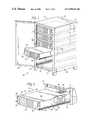
- FIG. 1is a perspective view of a rack mounted computer system including a plurality of servers housed within a rack or cabinet;
- FIG. 2is a detailed view of one of the servers of FIG. 1 withdrawn from the rack via a sliding support rail structure;
- FIG. 3is an exploded view of the server of FIG. 2 illustrating a manner in which a component-mounted sliding rail may be secured to the component housing;
- FIG. 4is an exploded view of a pair of support rails and slide assemblies for securing the structure of FIG. 3 within a supporting component rack;
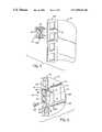
- FIG. 5is a perspective view of a nut subassembly for use in securing the support rails of FIG. 4 within a component rack;
- FIG. 6is a perspective view of a portion of a support rail of the type shown in FIG. 4 illustrating an exemplary manner in which the support rail may be mounted in the component rack;
- FIG. 7is a perspective view of a front portion of a support rail of the type shown in FIG. 4 following mounting to the component rack and after attachment of completed slide assemblies including rails of the type shown in FIGS. 3 and 4 ;
- FIG. 8is a perspective view of a cable support structure for use in the rack mounting system, permitting cables to be extensively coupled between the rear portion of the rack and a rear face of a server or other component;
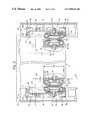
- FIG. 9is a partial sectional view of the fully assembled rail mounting system illustrating both left and right rail structures mounted to a server enclosure for supporting the server in the component rack.
- System 10includes a plurality of components or servers 12 , such as an individual server, supported in a vertical mounting rack 14 .
- rack 14is constructed within a storage cabinet 16 .
- Rack 14includes a rail system, designated generally by the reference numeral 18 , for supporting each individual server and for permitting the server to be recessed or inserted into the rack, or drawn from the rack for servicing, while remaining mechanically supported by cantilevered sliding rail arrangements as described more fully below.
- Rack 14 and cabinet 16include a front access opening 20 through which the servers may be retracted and reinserted, and a rear access opening 22 through which necessary connections may be made to each individual server for coupling the server to external components or to one another.
- Side panels 24extend between front and rear access openings 20 and 22 to enclose the internal volume of the cabinet in which the servers are positioned.
- a front access door 26is provided to close the cabinet when all of the servers are positioned in the rack.
- a similar access door(not shown) may be provided on rear access end 22 , and may include a grill or perforated cover through which air may flow for cooling of the servers in a manner generally known in the art.
- each server 12includes an outer enclosure 32 having lateral sides 34 .
- recesses 36are formed in lower regions of each lateral side to accommodate a sliding rail arrangement which supports the server in the rack, while permitting the server to be easily retracted and reinserted.
- An upper cover 38 of each servermay be removed to access internal components supported within enclosure 32 .
- the rail systemincludes a left rail assembly, designated generally by the reference numeral 56 and a right rail assembly 54 , when viewed from a position in front of the server.
- left rail assembly 56includes a left support rail 46 (see FIG. 4 ) and a left slide rail assembly 48 .
- right rail assembly 44includes a right support rail 50 and a right slide rail assembly 52 .
- the slide rail assembliesinclude rails designed to be fixed directly to the component enclosure, as illustrated in FIG. 3 , as well as additional rails for providing slidingly telescoping structures for ease of retraction and reinsertion of the component within the rack.
- the elements of these rail structures on the left and right sides of the componentare identical to one another but are assembled differently, thereby reducing the number of different parts in the rail system and facilitating assembly.
- the support rail assemblies on the left and right sides of the componentinclude symmetrical mounting regions for securement to respective slide rail assemblies. It has been found that this structure, described more fully below, again reduces the number of different parts in the rail system, while offering a low profile for attachment to the component, and assuring a sufficiently rigid support system for attachment to the rack.
- server 12is illustrated adjacent to left and right component rails 54 and 56 , respectively.
- Each component railincludes apertures 58 spaced along its length, which align with similar apertures 60 disposed in recesses 36 on each side of the server 12 .
- Nuts(not shown) retained within server 12 adjacent to recess 36 and behind apertures 60 , receive fasteners 62 which traverse apertures 58 and 60 for attachment of rails 54 and 56 to the server enclosure.
- Rails 54 and 56form part of slide rail assemblies 48 and 52 , respectively. The remaining components of these assemblies are illustrated in FIG. 4 .
- each support rail 46 and 50includes a rear securement bracket 64 and a front securement bracket 66 for fixing the support rails into the component rack as described below.
- a central region 68forms first and second mounting regions 70 and 72 , disposed symmetrically about a longitudinal axis 74 of each rail.
- the mounting regions 70 and 72each include apertures 76 for receiving fasteners used to attach the slide rail assemblies to the support rails.
- Other structures of each rail, including the rear and front securement brackets,are similarly symmetrical about the longitudinal access 74 of each rail, enabling identical rails to be used on either left or right sides of the rack by inverting the rail about the longitudinal axis.
- first mounting region 70is located in an upper position on right support rail 50 , while the same region is located in a lower position on left support rail 46 .
- the slide rail assembliesmay be secured in either mounting region.
- each bracket structureis conveniently formed as an integral piece with the support rail, such as by a series of stamping and bending operations.
- Each rear securement bracket 64includes a recessing extension 78 designed to place the mounting regions of the support rails in a recessed position within the rack with respect to the mounted component as described more fully below.
- the bracketsfurther include an attachment flange 80 generally parallel to the recessing extension, and a linking plate or extension 82 extending between the recessing extension and the attachment flange.
- Engagement tabs 84are formed on upper and lower extremities on each attachment flange 80 , and anti-rotation extensions 86 extend in a forward direction from each engagement tab.
- each rear securement bracketincludes a pair of apertures 88 for receiving fasteners for securing the support rail to the rack.
- Front securement brackets 66 on each support railinclude a front attachment flange 90 , having upper and lower engagement tabs 92 , each terminating in an anti-rotation extension 94 . While front attachment flanges 90 may be generally similar to attachment flanges 80 formed on rear securement brackets 64 , should be noted that the anti-rotation extensions 94 extend in a forward direction, permitting the rails to be easily secured to the rack structure by a forward motion engaging all of the anti-rotation extensions into the rack on both front and rear ends as described below. A pair of clinch nuts 96 are supported behind each front attachment flange 90 and aligned with apertures (not shown) in the front attachment flanges for receiving fasteners used to secure the brackets to the rack.
- slide rail assemblies 48 and 52each include an inner slide rail 98 designed to mate with a component rail 54 or 56 (see FIG. 3 ) to form a first telescoping set 100 of slide rails.
- the slide rail assemblieseach include a pair of such telescoping rail sets, including an outer pair of rails 102 and 104 which mate to form a second set 106 .
- Slide rail sets 100 and 106are secured to one another by securing rail 98 of the first set in a back-to-back relationship with rail 102 of the second set.
- Apertures 108are formed through the slide rail sets to permit the slide rail sets to be secured to one of the mounting regions 70 or 72 of a support rail via fasteners (not shown).
- FIGS. 5 , 6 , and 7The manner in which the rail assemblies described above are secured to the rack in accordance with a presently preferred arrangement is illustrated in FIGS. 5 , 6 , and 7 .
- rack 14is conveniently formed with an integral rear mounting flange 110 extending inwardly on either side of the rack.
- a series of mounting apertures 112are formed in the rear flange, such as in a square configuration, to facilitate mounting of the rails and other components of the system and to prevent twisting of the rails.
- a cage nut assembly 114is conveniently secured to the rear flange to receive fasteners extending through rear securement brackets 64 (see FIG. 6 ).
- each cage nut assembly 114includes a threaded nut 116 housed between an upper retaining clip 118 and a similar facing lower retaining clip 120 .
- Retaining clips 118 and 120are somewhat resilient, permitting them to be deformed slightly and inserted into an aperture 112 in rear flange 110 .
- the support railsmay be mounted to the rack as illustrated in FIG. 6 .
- the cage nut assembly 114is mounted in a location corresponding to the preferred level at which one of the mounting regions 70 or 72 of the support rail will be located.
- the support railssuch as right support rail 50 shown from a rear perspective view in FIG. 6 , are then positioned such that the rear flanges extend into a space between recessing extension 78 and attachment flange 80 , and are urged in a forward direction to engage anti-rotation extensions 86 into corresponding apertures 112 on either side of cage nut assembly 114 .
- a fastener 122is then inserted into cage nut assembly 114 through one of the apertures provided in attachment flange 80 of each rear securement bracket.
- anti-rotation extensions 86are lodged securely within apertures 112 to resist torsion of the support rail in the rack. Similar securement is performed on a front side of the rack as described more fully below.
- FIG. 6also illustrates a presently preferred arrangement of each support rail with respect to other features of the rack system.
- each support railincludes a first or upper flange 124 and a second or lower flange 126 provided on either side of an integral web 128 .
- Mounting regions 70 and 72are formed in web 128 , and flanges 124 and 126 lend a greater resistance to torsional loading of the rail, while assisting in locating and supporting the slide rail assemblies in the mounting regions.
- the resulting structurehas a height 130 as defined by the upper and lower flanges which is substantially greater than the reduced profile of the slide rail assemblies.
- the support regions 70 and 72 of the railsare recessed by a distance 132 in a direction generally away from the component. As discussed below with reference to FIG. 9 , this additional recessing affords a greater useful volume within the supported components as compared to heretofore known systems.
- rack 14also preferably includes an integral front mounting flange 134 on either side of the component access opening. Front flanges 134 include apertures 112 similar to those of the rear mounting flanges.
- each support railis secured to the rear mounting flanges, as described above with reference to FIG. 6 , the front securement bracket 66 of each rail is also located at a desired level or position with respect to a front flange 134 .
- the front securement bracket of the railis urged towards an inner side of the front flange to urge the anti-rotation extensions of the front securement bracket into corresponding apertures 112 .
- a fastener 136is then inserted and secured in one of the clinch nuts 96 (see FIG. 4 ) of the front securement bracket.
- each slide rail assembly setincludes flanges which mate to form inner and outer races of anti-friction bearings.
- each setincludes a rail forming outer races by virtue of upper and lower flanges 138 and 140 , and a smaller inner rail forming inner races by virtue of flanges 142 and 144 .
- a series of anti-friction bearing elements 146are disposed between the mutually facing inner and outer flanges to facilitate gliding or sliding motion of the smaller rail within the larger.
- stops or bumpers 148may be provided within the slide rail assemblies to limit motion of one or more of the mutually engaging rails with respect to one another.
- FIG. 8illustrates an exemplary configuration of a cable arm 150 used to support such cabling (not shown in FIG. 8 for the sake of clarity).
- Cable arm 150is designed to be secured both to the component 12 and to rack 14 and to articulate between the component and the rack as the component is slid or retracted from the rack, or slid back into or reinserted into the rack.
- the rear 152 of the component enclosuresupports a component interface bracket 154
- a rack interface bracket 156is secured to a rear flange 110 of the rack, such as via one or more fasteners 158 .
- Cable arm 150includes a component-side mounting bracket 160 which is secured to component interface bracket 154 by means of one or more fasteners 158 .
- a rack support bracket 162is secured to rack interface bracket 156 by means of similar fasteners 158 .
- rack interface bracket 156includes upper and lower anti-rotation flanges 159 which engage bracket 162 to prevent rotation of the cable arm and to maintain the cable arm in a cantilevered position behind component 12 .
- the cable arm assemblyfurther includes a series of support plates 164 pivotally secured to one another by hinges 166 .
- the cable arm assemblyis particularly well suited to maintaining cables in a desired envelope dimension of the component.
- a reference dimension 170 of the outer enclosure of component 12is preferably used as a basis for the overall height of the interfacing brackets and cable arm assembly components, such that all cable arm components and supported cables remain within the envelope dimension defined by the height 170 .
- This dimensional constrictionadvantageously facilitates insertion and removal of components within the rack without requiring partial dismantling of support structures of neighboring components.
- FIG. 9represents components of the fully assembled support and slide mounting structures described above and presently preferred dimensional relationships between the structures.
- identical left and right support rails of 46 and 50are mounted within rack 14 on left and right flanges of the rack.
- Symmetrical mounting regions on each support railreceive corresponding left and right slide rail assemblies 48 and 52 .
- the slide rail assembliesare mounted in lower positions on the support rails. However, where desired, the slide rail assemblies may be mounted in mutually facing upper positions.
- the preferred configuration of the support rail and slide rail assembliesfacilitates the use of identical components throughout the system.
- the support railsidentical to one another, but individual slide rail sets within the slide rail assemblies may similarly be identical.
- the foregoing structuresoffer the additional advantage of providing a low profile slide rail structure, while supporting the slide rail structure on a high moment of inertia support rail. Moreover, recessing of the support rails within the rack, while providing slide rail assemblies which extend into the region supporting the component allows a maximum width dimension to be employed in the design of the component enclosure. Thus, the slide rail assemblies extend into the component enclosure only by a dimension slightly greater than that of the lower recess, as represented by reference numeral 172 in FIG. 9 , thus providing an enhanced component enclosure extension 174 on either side of the component.
- the stacked sets of slide rails in the slide rail assemblyprovide a slide rail extension 176 which, in appropriate cases, may be further minimized by reduction in the width profile of the slide rail sets.
- the reduced height of the slide railsreduces the overall height dimension over which the rail support structure extends on each lateral side of the component.
- the height of the slide rail assembliesrepresented by reference numeral 178 in FIG. 9 , is approximately one half of the overall height of the support rails, allowing an approximately equal dimension to be added to the interior of the component enclosure and accessed upon removal of the upper cover of the enclosure.
Landscapes
- Engineering & Computer Science (AREA)
- General Engineering & Computer Science (AREA)
- Theoretical Computer Science (AREA)
- Human Computer Interaction (AREA)
- Physics & Mathematics (AREA)
- General Physics & Mathematics (AREA)
- Computer Hardware Design (AREA)
- Microelectronics & Electronic Packaging (AREA)
- Casings For Electric Apparatus (AREA)
Abstract
Description
Claims (30)
Priority Applications (1)
| Application Number | Priority Date | Filing Date | Title |
|---|---|---|---|
| US09/127,571US6988626B2 (en) | 1998-07-31 | 1998-07-31 | Computer component rack mounting arrangement |
Applications Claiming Priority (1)
| Application Number | Priority Date | Filing Date | Title |
|---|---|---|---|
| US09/127,571US6988626B2 (en) | 1998-07-31 | 1998-07-31 | Computer component rack mounting arrangement |
Publications (2)
| Publication Number | Publication Date |
|---|---|
| US20010037985A1 US20010037985A1 (en) | 2001-11-08 |
| US6988626B2true US6988626B2 (en) | 2006-01-24 |
Family
ID=22430786
Family Applications (1)
| Application Number | Title | Priority Date | Filing Date |
|---|---|---|---|
| US09/127,571Expired - LifetimeUS6988626B2 (en) | 1998-07-31 | 1998-07-31 | Computer component rack mounting arrangement |
Country Status (1)
| Country | Link |
|---|---|
| US (1) | US6988626B2 (en) |
Cited By (44)
| Publication number | Priority date | Publication date | Assignee | Title |
|---|---|---|---|---|
| US20020104942A1 (en)* | 2000-11-07 | 2002-08-08 | Mimlitch Robert H. | Apparatus and method for adapting two-post rack systems to support four-post rack mounted equipment |
| US20050052102A1 (en)* | 2001-12-06 | 2005-03-10 | Lauchner Craig E. | Method for installing a slide assembly for a computer server using dual flat springs |
| US20050087504A1 (en)* | 2003-10-24 | 2005-04-28 | Pin-Shian Wu | Mounting apparatus assembly for data storage devices |
| US20050254210A1 (en)* | 2004-05-14 | 2005-11-17 | Grady John R | Fan tray for electronics enclosure |
| US20060232718A1 (en)* | 2005-04-14 | 2006-10-19 | Chen-Sung Liao | Display apparatus |
| US20060283816A1 (en)* | 2005-06-21 | 2006-12-21 | Moore David C | Rack-mounted bracket assembly |
| US7201279B1 (en)* | 2002-07-18 | 2007-04-10 | Innovation First, Inc. | Sliding rack-mountable shelf for rack-mountable components |
| US20070097605A1 (en)* | 2005-10-28 | 2007-05-03 | International Business Machines Corporation | Actuation mechanism for mating electronic card interconnect systems |
| US20070231104A1 (en)* | 2006-03-30 | 2007-10-04 | Inventec Corporation | Track fixture |
| US20080035588A1 (en)* | 2006-08-09 | 2008-02-14 | Super Micro Computer, Inc. | Device for loading computer equipment |
| US20080067907A1 (en)* | 2006-09-20 | 2008-03-20 | King Slide Works Co., Ltd. | Slide bracket |
| US20080078899A1 (en)* | 2006-09-20 | 2008-04-03 | Ken-Ching Chen | Slide bracket |
| US20080087781A1 (en)* | 2006-10-17 | 2008-04-17 | Ken-Ching Chen | Slide bracket allowing front access for dismounting |
| US20080230496A1 (en)* | 2007-03-20 | 2008-09-25 | Gregory Henderson | Universal rack mount mechanism |
| US20080290051A1 (en)* | 2007-05-17 | 2008-11-27 | Manzi Steven F | Standalone open frame |
| US7542300B1 (en)* | 2005-03-04 | 2009-06-02 | Network Appliance, Inc. | Storage system chassis and components |
| US20090218301A1 (en)* | 2002-03-14 | 2009-09-03 | Innovation First, Inc., A Texas Corporation | Universal rack mountable shelf |
| WO2009121076A3 (en)* | 2008-03-28 | 2010-01-21 | Zonit Structured Solutions, Llc | Uniform equipment mounting system |
| US20100019637A1 (en)* | 2006-12-22 | 2010-01-28 | BSH Bosch und Siemens Hausgeräte GmbH | Telescopic extension |
| US20100046863A1 (en)* | 2008-08-20 | 2010-02-25 | Chi-Tsun Cheng | Drawable track assembly |
| US7798581B2 (en) | 2007-02-22 | 2010-09-21 | King Slide Works Co., Ltd. | Fast detachable slide bracket |
| US20110100936A1 (en)* | 2009-11-04 | 2011-05-05 | Inventec Corporation | Rail device and server |
| US20110100934A1 (en)* | 2009-11-03 | 2011-05-05 | Inventec Corporation | Rail device and server |
| US20110116233A1 (en)* | 2009-11-17 | 2011-05-19 | Beaudoin Denis J F | Fan Tray that is Installable and Removable from the Front and Back of a Network Element Chassis |
| US20110135224A1 (en)* | 2009-12-04 | 2011-06-09 | King Slide Works Co., Ltd. | Slide assembly |
| US20110226710A1 (en)* | 2010-03-17 | 2011-09-22 | Hong Fu Jin Precision Industry (Shenzhen) Co.,Ltd. | Mounting apparatus for electronic device |
| US20110233349A1 (en)* | 2010-03-26 | 2011-09-29 | Hong Fu Jin Precision Industry(Shenzhen) Co., Ltd | Support frame |
| US20120175477A1 (en)* | 2011-01-12 | 2012-07-12 | Hon Hai Precision Industry Co., Ltd. | Mounting apparatus for slide rail |
| CN103096683A (en)* | 2011-10-31 | 2013-05-08 | 鸿富锦精密工业(深圳)有限公司 | Cabinet |
| US20140003001A1 (en)* | 2012-06-29 | 2014-01-02 | Violin Memory, Inc. | Power supply and circuit module for data processing system |
| US20140055959A1 (en)* | 2011-05-11 | 2014-02-27 | Ion Manda | Rack module |
| US20140126129A1 (en)* | 2012-11-07 | 2014-05-08 | Dell Products L.P. | Chassis drawer for modular information handling resources |
| US8876232B2 (en) | 2011-10-27 | 2014-11-04 | Rsi Home Products Management, Inc. | Drawer glide mechanism |
| EP2929806A1 (en) | 2014-04-09 | 2015-10-14 | King Slide Works Co., Ltd. | Slide rail assembly |
| US9247814B2 (en) | 2014-03-31 | 2016-02-02 | King Slide Works Co., Ltd. | Slide rail assembly |
| CN105302257A (en)* | 2014-07-24 | 2016-02-03 | 南通霆云网络科技有限公司 | Multilayer node server |
| US20160177946A1 (en)* | 2013-08-09 | 2016-06-23 | Mhwirth Gmbh | Positive displacement pump |
| US9375084B2 (en) | 2014-05-09 | 2016-06-28 | Rsi Home Products Management, Inc. | Drawer glide mechanism |
| USD773215S1 (en)* | 2015-02-13 | 2016-12-06 | Kappler Med + Org Gmbh | Storage cabinet |
| US20180020832A1 (en)* | 2016-07-21 | 2018-01-25 | Grass America, Inc. | Frame for a movable furniture part |
| US20180140093A1 (en)* | 2016-11-22 | 2018-05-24 | King Slide Works Co., Ltd. | Supporting device for rail member |
| US20220250528A1 (en)* | 2021-02-09 | 2022-08-11 | Toyota Jidosha Kabushiki Kaisha | Rack and delivery vehicle including the same |
| USD989749S1 (en)* | 2021-02-03 | 2023-06-20 | Sonos, Inc. | Audio device rack mount |
| US12193567B2 (en) | 2012-03-02 | 2025-01-14 | American Woodmark Management Company | Drawer glide mechanism |
Families Citing this family (49)
| Publication number | Priority date | Publication date | Assignee | Title |
|---|---|---|---|---|
| US6681942B2 (en)* | 1999-10-27 | 2004-01-27 | Hewlett-Packard Development Company | Rack mount assembly |
| US6702412B2 (en) | 2001-09-19 | 2004-03-09 | Hewlett-Packard Development Company, L.P. | Expandable slide and rail assembly for a rack and method of installing same |
| US6976745B2 (en)* | 2001-09-19 | 2005-12-20 | Hewlett-Packard Development Company, L.P. | Snap-on slide and rail assembly |
| DE10164173A1 (en)* | 2001-12-27 | 2003-10-09 | Fujitsu Siemens Computers Gmbh | Installation kit for system carriers in server racks |
| US6893091B1 (en)* | 2002-05-07 | 2005-05-17 | Martin Fenner | Side-vented enclosure and telescoping rail system |
| US6867980B2 (en)* | 2002-06-10 | 2005-03-15 | Sun Microsystems, Inc. | Cable management system |
| US6854605B2 (en)* | 2002-06-10 | 2005-02-15 | Sun Microsystems, Inc. | Cable management system |
| US6811039B2 (en)* | 2002-12-06 | 2004-11-02 | King Slide Works Co., Ltd. | Detachable device of a cable management arm for furniture |
| US7364245B2 (en) | 2002-12-18 | 2008-04-29 | Pentair Electronic Packaging Company | Lateral alignment device |
| US7111913B2 (en) | 2002-12-18 | 2006-09-26 | Pentair Electronic Packaging | Telescoping slide rail with latching and alignment mechanisms |
| US7012808B2 (en) | 2002-12-20 | 2006-03-14 | Hewlett-Packard Development Company, L.P. | Multi-configurable telecommunications rack mounting system and method incorporating same |
| US7137512B2 (en) | 2003-02-19 | 2006-11-21 | Hewlett-Packard Development Company, L.P. | Removable rails for use on racks |
| JP4012091B2 (en)* | 2003-02-20 | 2007-11-21 | 富士通株式会社 | Electronic device cooling structure and information processing apparatus |
| DE20305064U1 (en)* | 2003-03-28 | 2003-09-18 | Hollein, Rudolf, 89551 Königsbronn | Multifunctional AV trolley / mobile classroom |
| US6922336B2 (en) | 2003-04-11 | 2005-07-26 | Hewlett-Packard Development Company, L.P. | Pivoted field replaceable unit apparatus and method |
| TW586653U (en)* | 2003-04-18 | 2004-05-01 | Delta Electronics Inc | Heat dissipation module with twin centrifugal fans |
| US7026551B2 (en)* | 2003-05-01 | 2006-04-11 | Hewlett-Packard Development Company, L.P. | Drop down cable arm |
| US7102887B2 (en)* | 2003-05-15 | 2006-09-05 | Finisar Corporation | Housing for hot pluggable network taps |
| US7810653B2 (en) | 2003-10-02 | 2010-10-12 | Hewlett-Packard Development Company, L.P. | Apparatus and method for mounting a device to a rack system |
| EP1555866A3 (en)* | 2004-01-16 | 2009-02-25 | Pentair Electronic Packaging Co. | Universal connector for mounting a telescoping slide rail assembly in a rack |
| US7188916B2 (en)* | 2004-03-29 | 2007-03-13 | Emc Corporation | Adjustable side rails and method of attaching same to mounting rails of cabinet racks |
| US7204373B2 (en)* | 2004-04-02 | 2007-04-17 | American Grease Stick Company | Angulated package and display system |
| JP2005323648A (en)* | 2004-05-12 | 2005-11-24 | Iris Ohyama Inc | Chest |
| US20060125358A1 (en)* | 2004-12-14 | 2006-06-15 | Robert Vernon Williamson | Console embedded server rack |
| US20060152115A1 (en)* | 2005-01-07 | 2006-07-13 | William Dubon | Adjustable reinforcing bracket for telescoping slide rail assembly |
| US7744178B2 (en)* | 2005-07-19 | 2010-06-29 | International Business Machines Corporation | Rack-mounted rail system |
| CN2849262Y (en)* | 2005-09-21 | 2006-12-20 | 鸿富锦精密工业(深圳)有限公司 | Fixing device of fan |
| US7301756B2 (en)* | 2006-03-23 | 2007-11-27 | Adc Telecommunications, Inc. | System for mounting modules in a rack mounted chassis |
| US20070283710A1 (en)* | 2006-06-12 | 2007-12-13 | Sun Microsystems, Inc. | Method and system for cooling electronic equipment |
| US20080144293A1 (en)* | 2006-12-19 | 2008-06-19 | International Business Machines Corporation | Cable Management System and Method for Rack Mountable Equipment |
| CN101460024B (en)* | 2007-12-14 | 2013-01-09 | 鸿富锦精密工业(深圳)有限公司 | Machine cabinet |
| US20090184072A1 (en)* | 2008-01-18 | 2009-07-23 | International Business Machines Corporation | Adjustable rack apparatus |
| US20090219701A1 (en)* | 2008-02-29 | 2009-09-03 | Sui-An Wu | Sliding flat panel display and keyboard module |
| US20110062101A1 (en)* | 2009-03-09 | 2011-03-17 | Todd Jr Everett Lee | Pivotable shelving system |
| US8335080B2 (en)* | 2009-04-20 | 2012-12-18 | Infortrend Technology, Inc. | Sliding rail having anti-tilting mechanism |
| TW201220023A (en)* | 2010-11-05 | 2012-05-16 | Inventec Corp | Server rack structure |
| US9326414B2 (en) | 2010-12-10 | 2016-04-26 | Commscope Technologies Llc | Method and apparatus for mounting rack components on racks |
| TW201416838A (en)* | 2012-10-29 | 2014-05-01 | Hon Hai Prec Ind Co Ltd | Container data center |
| US9313914B2 (en)* | 2013-03-13 | 2016-04-12 | Jonathan Manufacturing Corporation | Slide assembly |
| CN106104022B (en) | 2014-03-12 | 2018-03-23 | 利塔尔两合公司 | For installing the fixed system of equipment, particularly household electrical appliance |
| TWI539882B (en)* | 2014-07-16 | 2016-06-21 | 廣達電腦股份有限公司 | Server |
| CN105848442A (en)* | 2015-01-15 | 2016-08-10 | 上海攀业氢能源科技有限公司 | Frame electronic equipment case of hydrogen energy power generation device |
| TWI578882B (en)* | 2015-07-15 | 2017-04-11 | King Slide Works Co Ltd | Slide rail assembly |
| US10037782B1 (en)* | 2017-06-06 | 2018-07-31 | Seagate Technology Llc | Storage array enclosure having sidewall step for use with expansion module |
| CN107861463B (en)* | 2017-12-18 | 2023-12-22 | 无锡优耐特能源科技有限公司 | Control device for authorizing permission of work |
| CN110602916B (en)* | 2019-09-26 | 2020-12-22 | 中国五冶集团有限公司 | Standard rack with nonstandard equipment fixing frame |
| CN114039687A (en)* | 2021-11-22 | 2022-02-11 | 杭州图南电子股份有限公司 | Multi-network integration emergency broadcasting system |
| CN115599176A (en)* | 2022-09-09 | 2023-01-13 | 上海顺诠科技有限公司(Cn) | server structure |
| US20240237255A9 (en)* | 2022-10-20 | 2024-07-11 | Dell Products L.P. | Over-rack component track system for modular data centers |
Citations (88)
| Publication number | Priority date | Publication date | Assignee | Title |
|---|---|---|---|---|
| US1231291A (en)* | 1916-09-21 | 1917-06-26 | Otho M Otte | Flour-bin for kitchen-cabinets. |
| US1614507A (en)* | 1924-09-04 | 1927-01-18 | Benedict F Vogt | Refrigerator |
| US1736108A (en)* | 1925-10-06 | 1929-11-19 | Art Metal Construction Co | Guide suspension for drawers and other movable elements |
| US1938908A (en)* | 1932-11-05 | 1933-12-12 | Shaw Walker Co | Mounting for sliding drawers |
| US1963220A (en)* | 1934-02-09 | 1934-06-19 | Gen Fireproofing Co | Drawer suspension |
| US2277702A (en) | 1940-12-14 | 1942-03-31 | Kennedy Mfg Company | Slide suspension |
| US2312326A (en)* | 1940-11-09 | 1943-03-02 | Genevieve M Earle | Refrigerator |
| US2346167A (en)* | 1942-06-22 | 1944-04-11 | Art Metal Construction Co | Progressive suspension for drawers and the like |
| US2679447A (en)* | 1951-09-24 | 1954-05-25 | Elizabeth Lois Bissman | Standardized interchangeable sliding drawer and track means therefor |
| US2960376A (en)* | 1957-10-14 | 1960-11-15 | Ray Myers Corp | Cabinet drawer suspension |
| US3059978A (en)* | 1961-03-13 | 1962-10-23 | Herbert S Fall | Horizontally circulating ball bearing vertical track |
| US3092429A (en) | 1960-05-23 | 1963-06-04 | David Ind | Chassis slide mechanism |
| US3133768A (en) | 1960-01-11 | 1964-05-19 | Markline Electronic Products I | Extensible chassis slide |
| US3377115A (en)* | 1967-02-27 | 1968-04-09 | Simmons Co | Drawer construction |
| US3488097A (en)* | 1968-07-26 | 1970-01-06 | Herbert S Fall | Heavy-duty drawer slide |
| US3650578A (en)* | 1969-09-10 | 1972-03-21 | Instrument Systems Corp | Quick disconnect slide structure |
| US3679274A (en) | 1970-09-25 | 1972-07-25 | Magic Chef Inc | Broiler drawer and slide |
| US3687505A (en)* | 1971-06-11 | 1972-08-29 | Fall Herbert S | Slide with synchronizing cable drive |
| US3712690A (en)* | 1971-06-11 | 1973-01-23 | Fall H | Slide structure |
| US3716284A (en)* | 1971-05-17 | 1973-02-13 | J Vogt | Vertically-adjustable drawer suspension |
| US3738716A (en)* | 1972-06-01 | 1973-06-12 | Fall H | Anti-creep ball bearing retainer for a drawer slide |
| US3778120A (en)* | 1972-02-15 | 1973-12-11 | M Hagen | Precision telescoping ball bearing drawer slide suspension for wood and metal furniture production |
| US3779623A (en) | 1971-06-23 | 1973-12-18 | Sekisui Chemical Co Ltd | Sectional rack |
| US3844627A (en) | 1972-11-10 | 1974-10-29 | K Gutner | Drawer guide |
| US3901564A (en)* | 1973-10-29 | 1975-08-26 | Henry P Armstrong | Drawer extensible slide chassis |
| US3912341A (en)* | 1973-10-23 | 1975-10-14 | Hardware Designers Inc | Progressive drawer slide |
| US4025138A (en)* | 1975-02-20 | 1977-05-24 | Halle Industries Inc. | Progressive slide assemblies |
| US4067632A (en)* | 1976-10-21 | 1978-01-10 | Buildex, Inc. | Drawer slide |
| US4191436A (en)* | 1978-07-25 | 1980-03-04 | The Streakers International Incorporated | Cabinet for use in mobile vehicle |
| US4194793A (en)* | 1976-09-09 | 1980-03-25 | Thomas Regout N.V. | Telescoping guide rail construction |
| US4324439A (en)* | 1980-01-10 | 1982-04-13 | Standard Precision, Inc. | Anti-rack system for wide drawers and the like |
| US4331369A (en)* | 1980-05-22 | 1982-05-25 | Scientific Micro Systems, Inc. | Chassis integrated slide |
| US4427245A (en)* | 1980-01-11 | 1984-01-24 | L.B. (Plastics) Limited | Drawer panel with track insert |
| US4479263A (en) | 1980-05-22 | 1984-10-23 | Siemens Aktiengesellschaft | Device for acquiring and processing electrical signals |
| US4479198A (en) | 1983-02-23 | 1984-10-23 | Honeywell Information Systems Inc. | Modular computer system |
| US4662761A (en)* | 1986-08-18 | 1987-05-05 | Knape & Vogt Manufacturing Company | Sequential drawer slide |
| US4772079A (en) | 1986-09-26 | 1988-09-20 | General Electric Co. | Cover assembly for removably mounted electronic equipment |
| US4925258A (en)* | 1988-06-10 | 1990-05-15 | Haworth Sub, Inc. | Office cabinet with flipper door and interlocking drawer and suspension assemblies |
| US4949934A (en) | 1989-04-05 | 1990-08-21 | Zenith Data Systems Corporation | Computer stand |
| US4977532A (en) | 1988-04-06 | 1990-12-11 | Xycom, Inc. | Industrial computer system with removable equipment drawer |
| US4988214A (en)* | 1986-08-18 | 1991-01-29 | Knape & Vogt Manufacturing Co. | Sequential drawer slide |
| US5090787A (en)* | 1987-01-12 | 1992-02-25 | Titus Tool Company Limited | Drawer runner |
| EP0512615A1 (en)* | 1991-05-02 | 1992-11-11 | Thomas Regout N.V. | Anti-rack system for drawers |
| US5164886A (en) | 1991-12-17 | 1992-11-17 | Chang Lien Sheng | Computer mainframe housing assembled with hooks and notches |
| US5197789A (en) | 1991-12-02 | 1993-03-30 | Lin Chung H | Connecting structure for a computer casing |
| US5208722A (en) | 1988-12-29 | 1993-05-04 | Compaq Computer Corporation | Tower system unit with angled drive bay |
| US5209572A (en)* | 1991-11-08 | 1993-05-11 | Accuride International, Inc. | Thin drawer slide |
| US5262923A (en) | 1991-06-21 | 1993-11-16 | Tandon Corporation | Railing with grounding tabs for grounding and mounting computer components in a computer |
| US5269598A (en) | 1992-10-08 | 1993-12-14 | Enlight Corporation | Personal computer component support structure |
| US5278351A (en) | 1991-04-02 | 1994-01-11 | Zeos International, Inc. | Personal computer cabinet cover with EMI clips |
| US5277615A (en) | 1992-09-24 | 1994-01-11 | Compaq Computer Corporation | Apparatus for removably supporting a plurality of hot plug-connected hard disk drives |
| DE4230706A1 (en) | 1992-09-14 | 1994-03-17 | Schock Metallwerk | Excerpt guide |
| US5388032A (en)* | 1993-05-04 | 1995-02-07 | Ibus Technologies, Inc. | Computer equipment monitor and discriminator |
| US5397176A (en) | 1992-10-02 | 1995-03-14 | Compaq Computer Corporation | Lockable computer tower unit housing |
| US5417496A (en)* | 1994-03-01 | 1995-05-23 | General Devices Co., Inc. | Ball bearing retainer for telescoping slide assembly |
| US5438476A (en) | 1992-11-20 | 1995-08-01 | Dell Usa, L.P. | Apparatus for upgrading a personal computer |
| US5460441A (en) | 1994-11-01 | 1995-10-24 | Compaq Computer Corporation | Rack-mounted computer apparatus |
| US5469037A (en) | 1994-06-02 | 1995-11-21 | Encore Computer Corporation | Linear accelerated device |
| US5472272A (en)* | 1992-08-20 | 1995-12-05 | Knape & Vogt Manufacturing Company | Precision drawer slide member |
| US5491611A (en) | 1993-09-10 | 1996-02-13 | Compaq Computer Corporation | Aligned quick connect cover for a computer system |
| US5495389A (en) | 1993-10-08 | 1996-02-27 | International Business Machines Corporation | Personal computer with configurational flexibility and service features |
| US5551775A (en)* | 1994-02-22 | 1996-09-03 | Accuride International, Inc. | Telescopic drawer slide with mechanical sequencing latch |
| US5571256A (en) | 1994-10-25 | 1996-11-05 | Compaq Computer Corporation | Server drawer slide mount apparatus for a rack-mounted computer system |
| US5572402A (en) | 1994-02-02 | 1996-11-05 | Samsung Electronics Co., Ltd. | Hard disk drive mounting assembly for a computer |
| US5632542A (en)* | 1995-06-07 | 1997-05-27 | Snap-On Technologies, Inc. | Drawer slide interlock apparatus |
| US5681102A (en)* | 1993-11-16 | 1997-10-28 | Borgstroms Platindustri Ab | Cassette for the construction of drawer cabinets |
| US5684671A (en) | 1995-08-22 | 1997-11-04 | Sequent Computer Systems, Inc. | Packaging architecture for a data server |
| US5717575A (en) | 1995-08-09 | 1998-02-10 | Digital Equipment Corporation | Board mounting system with self guiding interengagement |
| US5726866A (en) | 1996-02-14 | 1998-03-10 | Compaq Computer Corporation | Slide out readily accessible chassis having a trough for protecting cables and a hinge that includes a conduit |
| US5734557A (en) | 1996-09-13 | 1998-03-31 | Deli U.S.A., L.P. | Mounting assembly for electronic equipment |
| US5737184A (en) | 1996-06-04 | 1998-04-07 | Lai; Wen Hsien | Computer main circuit board rack structure |
| US5768097A (en) | 1996-04-26 | 1998-06-16 | Server Systems Technology, Inc. | Reconfigurable modular computer assembly having a main chassis with a removably attached face plate and at least one spacer removably attached to the face plate |
| US5772294A (en)* | 1994-08-31 | 1998-06-30 | Hendrich; Ronald D. | Multi-drawer cabinet having a drawer lock-out mechanism |
| US5784251A (en) | 1995-05-01 | 1998-07-21 | Apple Computer, Inc. | Appliance chassis having hingedly mounted section |
| US5784252A (en) | 1994-01-31 | 1998-07-21 | Olivetti & C., S.P.A. | Electronic processor unit having components mounted on a pivotal frame with lock mechanism |
| US5801921A (en)* | 1996-11-19 | 1998-09-01 | Symex, Inc. | Integrated data, voice, and video communication network |
| US5823647A (en)* | 1996-03-12 | 1998-10-20 | Mita Industrial Co., Ltd. | Paper holder mounting mechanism |
| US5833337A (en)* | 1997-05-09 | 1998-11-10 | Sequent Computer Systems, Inc. | Self-retaining rack slide |
| US6142590A (en)* | 1999-04-05 | 2000-11-07 | Central Industrial Supply Company | Two U vertical height keyboard and flatscreen drawer for a server system rack |
| US6181549B1 (en)* | 1997-06-24 | 2001-01-30 | Dell Products, L.P. | Chassis retaining system for an electronics rack |
| US6296338B1 (en)* | 1998-09-21 | 2001-10-02 | Thomas Regout B.V. | Telescopic bail having controllable positioning |
| US20020104942A1 (en) | 2000-11-07 | 2002-08-08 | Mimlitch Robert H. | Apparatus and method for adapting two-post rack systems to support four-post rack mounted equipment |
| US20030052580A1 (en) | 2001-09-19 | 2003-03-20 | Dobler Karl J. | Snap-on slide and rail assembly and method of assembling same |
| US20030193781A1 (en) | 2002-04-10 | 2003-10-16 | Mori Robert F. | System structure for convenient service access in a rack/cabinet |
| US20040080247A1 (en) | 2001-09-19 | 2004-04-29 | Dobler Karl J. | Expandable slide and rail assembly for a rack and method of installing same |
| US20040120123A1 (en) | 2002-12-20 | 2004-06-24 | Mayer David W. | Multi-configurable telecommunications rack mounting system and method incorporating same |
| US20040159618A1 (en) | 2003-02-19 | 2004-08-19 | Nguyen Minh H. | Removable rails for use on racks |
| US20040217073A1 (en) | 2003-05-01 | 2004-11-04 | Dobler Karl J. | System and method for utilizing a tool-less rail in a rack |
Family Cites Families (40)
| Publication number | Priority date | Publication date | Assignee | Title |
|---|---|---|---|---|
| JPH0428308A (en)* | 1990-05-23 | 1992-01-30 | Sugatsune Ind Co Ltd | Traveling controller for member |
| JPH0466423A (en)* | 1990-07-05 | 1992-03-02 | Minolta Camera Co Ltd | Picture forming device |
| US5284254A (en)* | 1992-06-24 | 1994-02-08 | B-Line Systems, Inc. | Rack for electrical equipment |
| US5313596A (en)* | 1993-01-05 | 1994-05-17 | Dell Usa Lp | Motorized portable computer/expansion chassis docking system |
| US5371344A (en)* | 1993-01-15 | 1994-12-06 | Indiana Cash Drawer Company, Inc. | Cash drawer |
| JP2991886B2 (en)* | 1993-03-09 | 1999-12-20 | 富士通株式会社 | Electronic switching system shelf assembly |
| US5637124A (en)* | 1995-03-23 | 1997-06-10 | Helical Dynamics, Inc. | Modular air cleaning system |
| US5586817A (en)* | 1995-09-05 | 1996-12-24 | Pitney Bowes Inc. | Drawer interlock apparatus |
| DE19607142C1 (en)* | 1996-02-26 | 1997-07-17 | Siemens Nixdorf Inf Syst | Guide rail assembly for electric device components guided on guide rails esp. for IFS Tower and S90 |
| DE29613357U1 (en)* | 1996-08-06 | 1997-12-04 | Mepla-Werke Lautenschläger GmbH & Co KG, 64354 Reinheim | Fastening arrangement of guide rails of pull-out guides |
| US5941621A (en)* | 1997-02-28 | 1999-08-24 | Digital Equipment Corporation | Cabinet slide mounting bracket |
| US6021047A (en)* | 1997-10-24 | 2000-02-01 | Dell U.S.A., L,P. | Computer and a rack mount system and method for a computer |
| US5839373A (en)* | 1997-12-31 | 1998-11-24 | Lin; Chin-Chih | Adjustable keyboard rack mounting structure |
| GB9803527D0 (en)* | 1998-02-19 | 1998-04-15 | Reddicliffe Edward A | A method of assembling a cabinet |
| US6201690B1 (en)* | 1998-09-01 | 2001-03-13 | Emc Corporation | Rack console assembly |
| US6070742A (en)* | 1998-10-28 | 2000-06-06 | Dell Usa, L.P. | Multi-segment, nesting, low profile cable management arm |
| US6259605B1 (en)* | 1998-12-22 | 2001-07-10 | Dell Usa, L.P. | Front accessible computer and chassis |
| US6231138B1 (en)* | 1999-03-10 | 2001-05-15 | Spacesaver Corporation | Cantilevered pull-out shelf system |
| US6490153B1 (en)* | 1999-08-06 | 2002-12-03 | California Digital Corporation | Computer system for highly-dense mounting of system components |
| US6185092B1 (en)* | 1999-09-03 | 2001-02-06 | Compaq Computer Corporation | Computer system with in-line switchbox mounting |
| US6385036B1 (en)* | 1999-09-10 | 2002-05-07 | Robert C. Chien | Screwless computer case assembly |
| US6230903B1 (en)* | 1999-10-27 | 2001-05-15 | Hewlett-Packard Company | Snap-on rack slide mounting system |
| US6681942B2 (en)* | 1999-10-27 | 2004-01-27 | Hewlett-Packard Development Company | Rack mount assembly |
| US6257683B1 (en)* | 2000-03-13 | 2001-07-10 | Jun-Long Yang | Detachable rail for a drawer track |
| US6574100B1 (en)* | 2000-06-30 | 2003-06-03 | Intel Corporation | Thin server with side vent holes and spacer rail |
| US6224177B1 (en)* | 2000-08-22 | 2001-05-01 | Yin Da Slide Co., Ltd. | Sliding track assembly |
| US6360900B1 (en)* | 2000-09-26 | 2002-03-26 | Nstor Corporation | Data storage chassis with adjustable rack mounting |
| US6305556B1 (en)* | 2000-10-26 | 2001-10-23 | Hewlett-Packard Company | Cable management solution for rack-mounted computers |
| US6424534B1 (en)* | 2000-10-26 | 2002-07-23 | Hewlett-Packard Company | Computer enclosure rack mounting system |
| US6422399B1 (en)* | 2000-11-21 | 2002-07-23 | Dell Products L.P. | Rack system and method having tool-less releasable arm assembly |
| US6588866B2 (en)* | 2001-04-27 | 2003-07-08 | Intel Corporation | Slide rail attachment |
| US6554142B2 (en)* | 2001-07-27 | 2003-04-29 | Dell Products L.P. | Variable mount rack system arm assembly |
| US6702124B2 (en)* | 2001-12-06 | 2004-03-09 | Hewlett-Packard Development Company, L.P. | Flat spring clip for tool-less slide installation |
| US6601713B2 (en)* | 2001-12-10 | 2003-08-05 | Hewlett-Packard Development Company, L.P. | Rack assembly that does not require tools for coupling slides together |
| US6547081B1 (en)* | 2001-12-10 | 2003-04-15 | Hewlett-Packard Company | Slide assembly for use in a rack assembly |
| US6666340B2 (en)* | 2001-12-18 | 2003-12-23 | Hewlett-Packard Development Company, L.P. | Universal rack rail |
| US6655534B2 (en)* | 2002-01-23 | 2003-12-02 | Dell Products L.P. | Configurable rack rail system for dual mount configurations |
| US6644480B2 (en)* | 2002-01-30 | 2003-11-11 | Hewlett-Packard Development Company, L.P. | Adjustable rackmount assembly with locking key |
| US6615992B1 (en)* | 2002-03-11 | 2003-09-09 | Hewlett-Packard Development Company L.P. | Adjustable rackmount assembly |
| US6773080B2 (en)* | 2002-12-06 | 2004-08-10 | King Slide Works, Co., Ltd. | Bracket device for a track assembly |
- 1998
- 1998-07-31USUS09/127,571patent/US6988626B2/ennot_activeExpired - Lifetime
Patent Citations (90)
| Publication number | Priority date | Publication date | Assignee | Title |
|---|---|---|---|---|
| US1231291A (en)* | 1916-09-21 | 1917-06-26 | Otho M Otte | Flour-bin for kitchen-cabinets. |
| US1614507A (en)* | 1924-09-04 | 1927-01-18 | Benedict F Vogt | Refrigerator |
| US1736108A (en)* | 1925-10-06 | 1929-11-19 | Art Metal Construction Co | Guide suspension for drawers and other movable elements |
| US1938908A (en)* | 1932-11-05 | 1933-12-12 | Shaw Walker Co | Mounting for sliding drawers |
| US1963220A (en)* | 1934-02-09 | 1934-06-19 | Gen Fireproofing Co | Drawer suspension |
| US2312326A (en)* | 1940-11-09 | 1943-03-02 | Genevieve M Earle | Refrigerator |
| US2277702A (en) | 1940-12-14 | 1942-03-31 | Kennedy Mfg Company | Slide suspension |
| US2346167A (en)* | 1942-06-22 | 1944-04-11 | Art Metal Construction Co | Progressive suspension for drawers and the like |
| US2679447A (en)* | 1951-09-24 | 1954-05-25 | Elizabeth Lois Bissman | Standardized interchangeable sliding drawer and track means therefor |
| US2960376A (en)* | 1957-10-14 | 1960-11-15 | Ray Myers Corp | Cabinet drawer suspension |
| US3133768A (en) | 1960-01-11 | 1964-05-19 | Markline Electronic Products I | Extensible chassis slide |
| US3092429A (en) | 1960-05-23 | 1963-06-04 | David Ind | Chassis slide mechanism |
| US3059978A (en)* | 1961-03-13 | 1962-10-23 | Herbert S Fall | Horizontally circulating ball bearing vertical track |
| US3377115A (en)* | 1967-02-27 | 1968-04-09 | Simmons Co | Drawer construction |
| US3488097A (en)* | 1968-07-26 | 1970-01-06 | Herbert S Fall | Heavy-duty drawer slide |
| US3650578A (en)* | 1969-09-10 | 1972-03-21 | Instrument Systems Corp | Quick disconnect slide structure |
| US3679274A (en) | 1970-09-25 | 1972-07-25 | Magic Chef Inc | Broiler drawer and slide |
| US3716284A (en)* | 1971-05-17 | 1973-02-13 | J Vogt | Vertically-adjustable drawer suspension |
| US3687505A (en)* | 1971-06-11 | 1972-08-29 | Fall Herbert S | Slide with synchronizing cable drive |
| US3712690A (en)* | 1971-06-11 | 1973-01-23 | Fall H | Slide structure |
| US3779623A (en) | 1971-06-23 | 1973-12-18 | Sekisui Chemical Co Ltd | Sectional rack |
| US3778120A (en)* | 1972-02-15 | 1973-12-11 | M Hagen | Precision telescoping ball bearing drawer slide suspension for wood and metal furniture production |
| US3738716A (en)* | 1972-06-01 | 1973-06-12 | Fall H | Anti-creep ball bearing retainer for a drawer slide |
| US3844627A (en) | 1972-11-10 | 1974-10-29 | K Gutner | Drawer guide |
| US3912341A (en)* | 1973-10-23 | 1975-10-14 | Hardware Designers Inc | Progressive drawer slide |
| US3901564A (en)* | 1973-10-29 | 1975-08-26 | Henry P Armstrong | Drawer extensible slide chassis |
| US4025138A (en)* | 1975-02-20 | 1977-05-24 | Halle Industries Inc. | Progressive slide assemblies |
| US4194793A (en)* | 1976-09-09 | 1980-03-25 | Thomas Regout N.V. | Telescoping guide rail construction |
| US4067632A (en)* | 1976-10-21 | 1978-01-10 | Buildex, Inc. | Drawer slide |
| US4191436A (en)* | 1978-07-25 | 1980-03-04 | The Streakers International Incorporated | Cabinet for use in mobile vehicle |
| US4324439A (en)* | 1980-01-10 | 1982-04-13 | Standard Precision, Inc. | Anti-rack system for wide drawers and the like |
| US4427245A (en)* | 1980-01-11 | 1984-01-24 | L.B. (Plastics) Limited | Drawer panel with track insert |
| US4479263A (en) | 1980-05-22 | 1984-10-23 | Siemens Aktiengesellschaft | Device for acquiring and processing electrical signals |
| US4331369A (en)* | 1980-05-22 | 1982-05-25 | Scientific Micro Systems, Inc. | Chassis integrated slide |
| US4479198A (en) | 1983-02-23 | 1984-10-23 | Honeywell Information Systems Inc. | Modular computer system |
| US4662761A (en)* | 1986-08-18 | 1987-05-05 | Knape & Vogt Manufacturing Company | Sequential drawer slide |
| US4988214A (en)* | 1986-08-18 | 1991-01-29 | Knape & Vogt Manufacturing Co. | Sequential drawer slide |
| US4772079A (en) | 1986-09-26 | 1988-09-20 | General Electric Co. | Cover assembly for removably mounted electronic equipment |
| US5090787A (en)* | 1987-01-12 | 1992-02-25 | Titus Tool Company Limited | Drawer runner |
| US4977532A (en) | 1988-04-06 | 1990-12-11 | Xycom, Inc. | Industrial computer system with removable equipment drawer |
| US4925258A (en)* | 1988-06-10 | 1990-05-15 | Haworth Sub, Inc. | Office cabinet with flipper door and interlocking drawer and suspension assemblies |
| US5208722A (en) | 1988-12-29 | 1993-05-04 | Compaq Computer Corporation | Tower system unit with angled drive bay |
| US4949934A (en) | 1989-04-05 | 1990-08-21 | Zenith Data Systems Corporation | Computer stand |
| US5278351A (en) | 1991-04-02 | 1994-01-11 | Zeos International, Inc. | Personal computer cabinet cover with EMI clips |
| EP0512615A1 (en)* | 1991-05-02 | 1992-11-11 | Thomas Regout N.V. | Anti-rack system for drawers |
| US5262923A (en) | 1991-06-21 | 1993-11-16 | Tandon Corporation | Railing with grounding tabs for grounding and mounting computer components in a computer |
| US5209572A (en)* | 1991-11-08 | 1993-05-11 | Accuride International, Inc. | Thin drawer slide |
| US5197789A (en) | 1991-12-02 | 1993-03-30 | Lin Chung H | Connecting structure for a computer casing |
| US5164886A (en) | 1991-12-17 | 1992-11-17 | Chang Lien Sheng | Computer mainframe housing assembled with hooks and notches |
| US5472272A (en)* | 1992-08-20 | 1995-12-05 | Knape & Vogt Manufacturing Company | Precision drawer slide member |
| DE4230706A1 (en) | 1992-09-14 | 1994-03-17 | Schock Metallwerk | Excerpt guide |
| US5277615A (en) | 1992-09-24 | 1994-01-11 | Compaq Computer Corporation | Apparatus for removably supporting a plurality of hot plug-connected hard disk drives |
| US5340340A (en) | 1992-09-24 | 1994-08-23 | Compaq Computer Corporation | Apparatus for removably supporting a plurality of hot plug-connected hard disk drives |
| US5397176A (en) | 1992-10-02 | 1995-03-14 | Compaq Computer Corporation | Lockable computer tower unit housing |
| US5269598A (en) | 1992-10-08 | 1993-12-14 | Enlight Corporation | Personal computer component support structure |
| US5438476A (en) | 1992-11-20 | 1995-08-01 | Dell Usa, L.P. | Apparatus for upgrading a personal computer |
| US5388032A (en)* | 1993-05-04 | 1995-02-07 | Ibus Technologies, Inc. | Computer equipment monitor and discriminator |
| US5491611A (en) | 1993-09-10 | 1996-02-13 | Compaq Computer Corporation | Aligned quick connect cover for a computer system |
| US5495389A (en) | 1993-10-08 | 1996-02-27 | International Business Machines Corporation | Personal computer with configurational flexibility and service features |
| US5598318A (en) | 1993-10-08 | 1997-01-28 | International Business Machines Corporation | Personal computer with configurational flexibility and service features |
| US5681102A (en)* | 1993-11-16 | 1997-10-28 | Borgstroms Platindustri Ab | Cassette for the construction of drawer cabinets |
| US5784252A (en) | 1994-01-31 | 1998-07-21 | Olivetti & C., S.P.A. | Electronic processor unit having components mounted on a pivotal frame with lock mechanism |
| US5572402A (en) | 1994-02-02 | 1996-11-05 | Samsung Electronics Co., Ltd. | Hard disk drive mounting assembly for a computer |
| US5551775A (en)* | 1994-02-22 | 1996-09-03 | Accuride International, Inc. | Telescopic drawer slide with mechanical sequencing latch |
| US5417496A (en)* | 1994-03-01 | 1995-05-23 | General Devices Co., Inc. | Ball bearing retainer for telescoping slide assembly |
| US5469037A (en) | 1994-06-02 | 1995-11-21 | Encore Computer Corporation | Linear accelerated device |
| US5772294A (en)* | 1994-08-31 | 1998-06-30 | Hendrich; Ronald D. | Multi-drawer cabinet having a drawer lock-out mechanism |
| US5571256A (en) | 1994-10-25 | 1996-11-05 | Compaq Computer Corporation | Server drawer slide mount apparatus for a rack-mounted computer system |
| US5460441A (en) | 1994-11-01 | 1995-10-24 | Compaq Computer Corporation | Rack-mounted computer apparatus |
| US5784251A (en) | 1995-05-01 | 1998-07-21 | Apple Computer, Inc. | Appliance chassis having hingedly mounted section |
| US5632542A (en)* | 1995-06-07 | 1997-05-27 | Snap-On Technologies, Inc. | Drawer slide interlock apparatus |
| US5717575A (en) | 1995-08-09 | 1998-02-10 | Digital Equipment Corporation | Board mounting system with self guiding interengagement |
| US5684671A (en) | 1995-08-22 | 1997-11-04 | Sequent Computer Systems, Inc. | Packaging architecture for a data server |
| US5726866A (en) | 1996-02-14 | 1998-03-10 | Compaq Computer Corporation | Slide out readily accessible chassis having a trough for protecting cables and a hinge that includes a conduit |
| US5823647A (en)* | 1996-03-12 | 1998-10-20 | Mita Industrial Co., Ltd. | Paper holder mounting mechanism |
| US5768097A (en) | 1996-04-26 | 1998-06-16 | Server Systems Technology, Inc. | Reconfigurable modular computer assembly having a main chassis with a removably attached face plate and at least one spacer removably attached to the face plate |
| US5737184A (en) | 1996-06-04 | 1998-04-07 | Lai; Wen Hsien | Computer main circuit board rack structure |
| US5734557A (en) | 1996-09-13 | 1998-03-31 | Deli U.S.A., L.P. | Mounting assembly for electronic equipment |
| US5801921A (en)* | 1996-11-19 | 1998-09-01 | Symex, Inc. | Integrated data, voice, and video communication network |
| US5833337A (en)* | 1997-05-09 | 1998-11-10 | Sequent Computer Systems, Inc. | Self-retaining rack slide |
| US6181549B1 (en)* | 1997-06-24 | 2001-01-30 | Dell Products, L.P. | Chassis retaining system for an electronics rack |
| US6296338B1 (en)* | 1998-09-21 | 2001-10-02 | Thomas Regout B.V. | Telescopic bail having controllable positioning |
| US6142590A (en)* | 1999-04-05 | 2000-11-07 | Central Industrial Supply Company | Two U vertical height keyboard and flatscreen drawer for a server system rack |
| US20020104942A1 (en) | 2000-11-07 | 2002-08-08 | Mimlitch Robert H. | Apparatus and method for adapting two-post rack systems to support four-post rack mounted equipment |
| US20030052580A1 (en) | 2001-09-19 | 2003-03-20 | Dobler Karl J. | Snap-on slide and rail assembly and method of assembling same |
| US20040080247A1 (en) | 2001-09-19 | 2004-04-29 | Dobler Karl J. | Expandable slide and rail assembly for a rack and method of installing same |
| US20030193781A1 (en) | 2002-04-10 | 2003-10-16 | Mori Robert F. | System structure for convenient service access in a rack/cabinet |
| US20040120123A1 (en) | 2002-12-20 | 2004-06-24 | Mayer David W. | Multi-configurable telecommunications rack mounting system and method incorporating same |
| US20040159618A1 (en) | 2003-02-19 | 2004-08-19 | Nguyen Minh H. | Removable rails for use on racks |
| US20040217073A1 (en) | 2003-05-01 | 2004-11-04 | Dobler Karl J. | System and method for utilizing a tool-less rail in a rack |
Non-Patent Citations (6)
| Title |
|---|
| Bridge Assembly for Mounting Interchangeable Electromagnetic Devices, IBM Technical Disclosure Bulletin, vol. 29, No. 9, Feb. 1987, 2 pages. |
| COMPAQ Typhoon Mechanical Specification, Version 0.01, Nov. 8, 1994 by Joseph Allen, Systems Division of Compaq Computer Corporation, 15 pages. |
| Direct-Access Storage Device Commodity-Stacking Plates, IBM Technical Disclosure Bulletin, vol. 30, No. 1, Jun. 1987, 2 pages. |
| Spring-Loaded File Rails, IBM Technical Disclosure Bulletin, vol. 28, No. 12, May 1986, 3 pages. |
| U.S. Appl. No. 09/691,382, filed Oct. 18, 2000; Entitled: "Rack System for Mounting Electronic Devices"; Inventor: Bolognia et al. |
| Universal, Low-Cost Hard-File Mounting Assembly, IBM Technical Disclosure Bulletin, vol. 28, No. 6, Nov. 1985, 2 pages. |
Cited By (100)
| Publication number | Priority date | Publication date | Assignee | Title |
|---|---|---|---|---|
| US7275646B2 (en) | 2000-11-07 | 2007-10-02 | Innovation First, Inc. | Apparatus and method for adapting two-post rack systems to support four-post rack mounted equipment |
| US7591056B2 (en) | 2000-11-07 | 2009-09-22 | Innovation First, Inc. | Method for adapting two-post rack systems to support four-post rack mounted equipment |
| US20080175659A1 (en)* | 2000-11-07 | 2008-07-24 | Innovation First, Inc. | Apparatus and method for adapting two-post rack systems to support four-post rack mounted equipment |
| US20020104942A1 (en)* | 2000-11-07 | 2002-08-08 | Mimlitch Robert H. | Apparatus and method for adapting two-post rack systems to support four-post rack mounted equipment |
| US20050052102A1 (en)* | 2001-12-06 | 2005-03-10 | Lauchner Craig E. | Method for installing a slide assembly for a computer server using dual flat springs |
| US7992950B2 (en)* | 2001-12-06 | 2011-08-09 | Hewlett-Packard Development Company, L.P. | Method for installing a slide assembly for a computer server using dual flat springs |
| US7866488B2 (en) | 2002-03-14 | 2011-01-11 | Innovation First, Inc. | Universal rack mountable shelf |
| US20090218301A1 (en)* | 2002-03-14 | 2009-09-03 | Innovation First, Inc., A Texas Corporation | Universal rack mountable shelf |
| US20070227992A1 (en)* | 2002-07-18 | 2007-10-04 | Innovation First, Inc., A Texas Corporation | Sliding Rack-Mountable Shelf for Rack-Mountable Components |
| US7201279B1 (en)* | 2002-07-18 | 2007-04-10 | Innovation First, Inc. | Sliding rack-mountable shelf for rack-mountable components |
| US7806277B2 (en) | 2002-07-18 | 2010-10-05 | Innovation First, Inc. | Sliding rack-mountable shelf for rack-mountable components |
| US7318531B2 (en)* | 2003-10-24 | 2008-01-15 | Hon Hai Precision Industry Co., Ltd. | Mounting apparatus assembly for data storage devices |
| US20050087504A1 (en)* | 2003-10-24 | 2005-04-28 | Pin-Shian Wu | Mounting apparatus assembly for data storage devices |
| US20050254210A1 (en)* | 2004-05-14 | 2005-11-17 | Grady John R | Fan tray for electronics enclosure |
| US7408772B2 (en)* | 2004-05-14 | 2008-08-05 | Hewlett-Packard Development Company, L.P. | Fan tray electronics enclosure |
| US7542300B1 (en)* | 2005-03-04 | 2009-06-02 | Network Appliance, Inc. | Storage system chassis and components |
| US20060232718A1 (en)* | 2005-04-14 | 2006-10-19 | Chen-Sung Liao | Display apparatus |
| US20060283816A1 (en)* | 2005-06-21 | 2006-12-21 | Moore David C | Rack-mounted bracket assembly |
| US7505251B2 (en)* | 2005-10-28 | 2009-03-17 | International Business Machines Corporation | Actuation mechanism for mating electronic card interconnect systems |
| US20070097605A1 (en)* | 2005-10-28 | 2007-05-03 | International Business Machines Corporation | Actuation mechanism for mating electronic card interconnect systems |
| US20070231104A1 (en)* | 2006-03-30 | 2007-10-04 | Inventec Corporation | Track fixture |
| US20080035588A1 (en)* | 2006-08-09 | 2008-02-14 | Super Micro Computer, Inc. | Device for loading computer equipment |
| US20080078899A1 (en)* | 2006-09-20 | 2008-04-03 | Ken-Ching Chen | Slide bracket |
| US20080067907A1 (en)* | 2006-09-20 | 2008-03-20 | King Slide Works Co., Ltd. | Slide bracket |
| US7699279B2 (en) | 2006-09-20 | 2010-04-20 | King Slide Works Co., Ltd. | Slide bracket |
| US7552899B2 (en) | 2006-10-17 | 2009-06-30 | King Slide Works Co., Ltd. | Slide bracket allowing front access for dismounting |
| US20080087781A1 (en)* | 2006-10-17 | 2008-04-17 | Ken-Ching Chen | Slide bracket allowing front access for dismounting |
| US20100019637A1 (en)* | 2006-12-22 | 2010-01-28 | BSH Bosch und Siemens Hausgeräte GmbH | Telescopic extension |
| US7798581B2 (en) | 2007-02-22 | 2010-09-21 | King Slide Works Co., Ltd. | Fast detachable slide bracket |
| US20080230496A1 (en)* | 2007-03-20 | 2008-09-25 | Gregory Henderson | Universal rack mount mechanism |
| US7934607B2 (en) | 2007-03-20 | 2011-05-03 | Dell Products L.P. | Universal rack mount mechanism |
| US8020715B2 (en) | 2007-05-17 | 2011-09-20 | Hewlett-Packard Development Company, L.P. | Standalone open frame |
| US20080290051A1 (en)* | 2007-05-17 | 2008-11-27 | Manzi Steven F | Standalone open frame |
| US8272520B2 (en)* | 2007-05-17 | 2012-09-25 | Hewlett-Packard Development Company, L.P. | Standalone open frame |
| US20120000054A1 (en)* | 2007-05-17 | 2012-01-05 | Manzi Steven F | Standalone open frame |
| US20250071928A1 (en)* | 2008-03-28 | 2025-02-27 | Zonit Structured Solutions, Llc | Uniform equipment mounting system |
| US11895800B2 (en)* | 2008-03-28 | 2024-02-06 | Zonit Structured Solutions, Llc | Uniform equipment mounting system |
| US10034406B2 (en)* | 2008-03-28 | 2018-07-24 | Zonit Structured Solutions, Llc | Uniform equipment mounting system |
| CN102046046B (en)* | 2008-03-28 | 2017-08-29 | 佐尼特结构解决方案有限责任公司 | Unified apparatus installation system |
| US20150163953A1 (en)* | 2008-03-28 | 2015-06-11 | Zonit Structure Solutions, Llc | Uniform equipment mounting system |
| US10834841B2 (en)* | 2008-03-28 | 2020-11-10 | Zonit Structured Solutions, Llc | Uniform equipment mounting system |
| US8801122B2 (en)* | 2008-03-28 | 2014-08-12 | Zonit Structured Solutions, Llc | Uniform equipment mounting system |
| US11439034B2 (en)* | 2008-03-28 | 2022-09-06 | Zonit Structured Solutions, Llc | Uniform equipment mounting system |
| US20230247790A1 (en)* | 2008-03-28 | 2023-08-03 | Zonit Structured Solutions, Llc | Uniform equipment mounting system |
| WO2009121076A3 (en)* | 2008-03-28 | 2010-01-21 | Zonit Structured Solutions, Llc | Uniform equipment mounting system |
| CN102046046A (en)* | 2008-03-28 | 2011-05-04 | 佐尼特结构解决方案有限责任公司 | Uniform equipment mounting system |
| US20120091075A1 (en)* | 2008-03-28 | 2012-04-19 | Zonit Structured Solutions, Llc | Uniform equipment mounting system |
| US12356577B2 (en)* | 2008-03-28 | 2025-07-08 | Zonit Structured Solutions, Llc | Uniform equipment mounting system |
| US20100046863A1 (en)* | 2008-08-20 | 2010-02-25 | Chi-Tsun Cheng | Drawable track assembly |
| US8002470B2 (en)* | 2008-08-20 | 2011-08-23 | Lif J.K. Corporation | Drawable track assembly |
| US20110100934A1 (en)* | 2009-11-03 | 2011-05-05 | Inventec Corporation | Rail device and server |
| US8474924B2 (en)* | 2009-11-03 | 2013-07-02 | Inventec Corporation | Rail device and server |
| US8469467B2 (en)* | 2009-11-04 | 2013-06-25 | Inventec Corporation | Rail device and server |
| US20110100936A1 (en)* | 2009-11-04 | 2011-05-05 | Inventec Corporation | Rail device and server |
| US8116082B2 (en)* | 2009-11-17 | 2012-02-14 | Telefonaktiebolaget L M Ericsson (Publ) | Fan tray that is installable and removable from the front and back of a network element chassis |
| US20110116233A1 (en)* | 2009-11-17 | 2011-05-19 | Beaudoin Denis J F | Fan Tray that is Installable and Removable from the Front and Back of a Network Element Chassis |
| US8147011B2 (en)* | 2009-12-04 | 2012-04-03 | King Slide Works Co., Ltd. | Slide assembly |
| US20110135224A1 (en)* | 2009-12-04 | 2011-06-09 | King Slide Works Co., Ltd. | Slide assembly |
| US8443987B2 (en)* | 2010-03-17 | 2013-05-21 | Hong Fu Jin Precision Industry (Shenzhen) Co., Ltd. | Mounting apparatus for electronic device |
| US20110226710A1 (en)* | 2010-03-17 | 2011-09-22 | Hong Fu Jin Precision Industry (Shenzhen) Co.,Ltd. | Mounting apparatus for electronic device |
| US20110233349A1 (en)* | 2010-03-26 | 2011-09-29 | Hong Fu Jin Precision Industry(Shenzhen) Co., Ltd | Support frame |
| US8322668B2 (en)* | 2011-01-12 | 2012-12-04 | Hon Hai Precision Industry Co., Ltd. | Mounting apparatus for slide rail |
| US20120175477A1 (en)* | 2011-01-12 | 2012-07-12 | Hon Hai Precision Industry Co., Ltd. | Mounting apparatus for slide rail |
| US9516777B2 (en)* | 2011-05-11 | 2016-12-06 | Ion Manda | Rack module |
| US20140055959A1 (en)* | 2011-05-11 | 2014-02-27 | Ion Manda | Rack module |
| US10729240B2 (en) | 2011-10-27 | 2020-08-04 | Rsi Home Products Management, Inc. | Drawer glide mechanism |
| US9398808B2 (en) | 2011-10-27 | 2016-07-26 | Rsi Home Products Management, Inc. | Drawer glide mechanism |
| US12161222B2 (en) | 2011-10-27 | 2024-12-10 | American Woodmark Management Company | Drawer glide mechanism |
| US8876232B2 (en) | 2011-10-27 | 2014-11-04 | Rsi Home Products Management, Inc. | Drawer glide mechanism |
| US10292495B2 (en) | 2011-10-27 | 2019-05-21 | Rsi Home Products Management, Inc. | Drawer glide mechanism |
| US11779112B2 (en) | 2011-10-27 | 2023-10-10 | American Woodmark Management Company | Drawer glide mechanism |
| US11259633B2 (en) | 2011-10-27 | 2022-03-01 | American Woodmark Management Company | Drawer glide mechanism |
| CN103096683A (en)* | 2011-10-31 | 2013-05-08 | 鸿富锦精密工业(深圳)有限公司 | Cabinet |
| US12193567B2 (en) | 2012-03-02 | 2025-01-14 | American Woodmark Management Company | Drawer glide mechanism |
| US20140003001A1 (en)* | 2012-06-29 | 2014-01-02 | Violin Memory, Inc. | Power supply and circuit module for data processing system |
| US9904329B2 (en)* | 2012-06-29 | 2018-02-27 | Violin Systems Llc | Power supply and circuit module for data processing system |
| US9167705B2 (en)* | 2012-11-07 | 2015-10-20 | Dell Products L.P. | Chassis drawer for modular information handling resources |
| US9756745B2 (en)* | 2012-11-07 | 2017-09-05 | Dell Products L.P. | Chassis drawer for modular information handling resources |
| US20150359118A1 (en)* | 2012-11-07 | 2015-12-10 | Dell Products L.P. | Chassis drawer for modular information handlign resources |
| US20140126129A1 (en)* | 2012-11-07 | 2014-05-08 | Dell Products L.P. | Chassis drawer for modular information handling resources |
| US10190583B2 (en)* | 2013-08-09 | 2019-01-29 | Mhwirth Gmbh | Positive displacement pump |
| US20160177946A1 (en)* | 2013-08-09 | 2016-06-23 | Mhwirth Gmbh | Positive displacement pump |
| US9247814B2 (en) | 2014-03-31 | 2016-02-02 | King Slide Works Co., Ltd. | Slide rail assembly |
| EP2929806A1 (en) | 2014-04-09 | 2015-10-14 | King Slide Works Co., Ltd. | Slide rail assembly |
| US9756942B2 (en) | 2014-05-09 | 2017-09-12 | Rsi Home Products Management, Inc. | Drawer glide mechanism |
| US10765208B2 (en) | 2014-05-09 | 2020-09-08 | Rsi Home Products Management, Inc. | Drawer glide mechanism |
| US10327549B2 (en) | 2014-05-09 | 2019-06-25 | Rsi Home Products Management, Inc. | Drawer glide mechanism |
| US11266238B2 (en) | 2014-05-09 | 2022-03-08 | American Woodmark Management Company | Drawer glide mechanism |
| US9375084B2 (en) | 2014-05-09 | 2016-06-28 | Rsi Home Products Management, Inc. | Drawer glide mechanism |
| CN105302257A (en)* | 2014-07-24 | 2016-02-03 | 南通霆云网络科技有限公司 | Multilayer node server |
| USD773215S1 (en)* | 2015-02-13 | 2016-12-06 | Kappler Med + Org Gmbh | Storage cabinet |
| US10299585B2 (en)* | 2016-07-21 | 2019-05-28 | Grass America, Inc. | Frame for a movable furniture part |
| US20180020832A1 (en)* | 2016-07-21 | 2018-01-25 | Grass America, Inc. | Frame for a movable furniture part |
| US11116316B2 (en) | 2016-11-22 | 2021-09-14 | King Slide Works Co., Ltd. | Supporting device for rail member |
| US10383440B2 (en)* | 2016-11-22 | 2019-08-20 | King Slide Works Co., Ltd. | Supporting device for rail member |
| JP2018083058A (en)* | 2016-11-22 | 2018-05-31 | 川湖科技股▲分▼有限公司 | Rail member support device |
| US20180140093A1 (en)* | 2016-11-22 | 2018-05-24 | King Slide Works Co., Ltd. | Supporting device for rail member |
| USD989749S1 (en)* | 2021-02-03 | 2023-06-20 | Sonos, Inc. | Audio device rack mount |
| US20220250528A1 (en)* | 2021-02-09 | 2022-08-11 | Toyota Jidosha Kabushiki Kaisha | Rack and delivery vehicle including the same |
| US12043159B2 (en)* | 2021-02-09 | 2024-07-23 | Toyota Jidosha Kabushiki Kaisha | Rack and delivery vehicle including the same |
Also Published As
| Publication number | Publication date |
|---|---|
| US20010037985A1 (en) | 2001-11-08 |
Similar Documents
| Publication | Publication Date | Title |
|---|---|---|
| US6988626B2 (en) | Computer component rack mounting arrangement | |
| US7258583B1 (en) | Cable management arm having cable retention members | |
| US6021047A (en) | Computer and a rack mount system and method for a computer | |
| US8025166B2 (en) | Tool-less rack rail system incorporating clamping mechanism | |
| US5544006A (en) | Computer chassis having flexible card guide for expansion card insertion and removal | |
| US6326547B1 (en) | Cable management system | |
| US6373707B1 (en) | Module mounting slide clamp mechanism | |
| US5510955A (en) | Cage in computer equipment for locking peripheral equipment therewithin using hooked lockpins | |
| US6659577B2 (en) | Dual flat springs for tool-less slide installation | |
| US6702124B2 (en) | Flat spring clip for tool-less slide installation | |
| US5638644A (en) | Wall support assembly | |
| US5626406A (en) | Integrated chassis slide assembly | |
| US6067233A (en) | Mounting brace and cable management apparatus and method | |
| US6535381B2 (en) | Hot swap drawer assembly | |
| US3759475A (en) | Rack mounted electronic module support mechanism | |
| CN88102439A (en) | The compact apparatus of electronic equipment in small-sized casing | |
| US20200275578A1 (en) | Rack-mounted device and electronic apparatus | |
| US20030226812A1 (en) | Cable management system | |
| US6547081B1 (en) | Slide assembly for use in a rack assembly | |
| EP0438014B1 (en) | Unitized central electronics complex construction | |
| US6853548B2 (en) | 1U rack mount equipment enclosure with increased structural support | |
| US8289697B2 (en) | Equipment racks utilizing rail engaging retaining brackets that limit chassis movement | |
| US7394651B2 (en) | Computer peripheral device mounting arrangement with two locking elements | |
| EP0250850A2 (en) | Modularized packaging system | |
| US7255234B2 (en) | Low profile support system for device rack-mounting |
Legal Events
| Date | Code | Title | Description |
|---|---|---|---|
| AS | Assignment | Owner name:COMPAQ COMPUTER CORPORATION, TEXAS Free format text:ASSIGNMENT OF ASSIGNORS INTEREST;ASSIGNORS:VARGHESE, PAILY T.;HASTINGS, ROBERT J.;WESTPHALL, PAUL E.;REEL/FRAME:009365/0863 Effective date:19980730 | |
| AS | Assignment | Owner name:COMPAQ INFORMATION TECHNOLOGIES GROUP, L.P., TEXAS Free format text:ASSIGNMENT OF ASSIGNORS INTEREST;ASSIGNOR:COMPAQ COMPUTER CORPORATION;REEL/FRAME:012402/0897 Effective date:20010620 | |
| AS | Assignment | Owner name:HEWLETT-PACKARD DEVELOPMENT COMPANY, L.P., TEXAS Free format text:CHANGE OF NAME;ASSIGNOR:COMPAQ INFORMATION TECHNOLOGIES GROUP L.P.;REEL/FRAME:014177/0428 Effective date:20021001 Owner name:HEWLETT-PACKARD DEVELOPMENT COMPANY, L.P.,TEXAS Free format text:CHANGE OF NAME;ASSIGNOR:COMPAQ INFORMATION TECHNOLOGIES GROUP L.P.;REEL/FRAME:014177/0428 Effective date:20021001 | |
| STCF | Information on status: patent grant | Free format text:PATENTED CASE | |
| FPAY | Fee payment | Year of fee payment:4 | |
| FPAY | Fee payment | Year of fee payment:8 | |
| AS | Assignment | Owner name:HEWLETT PACKARD ENTERPRISE DEVELOPMENT LP, TEXAS Free format text:ASSIGNMENT OF ASSIGNORS INTEREST;ASSIGNOR:HEWLETT-PACKARD DEVELOPMENT COMPANY, L.P.;REEL/FRAME:037079/0001 Effective date:20151027 | |
| FPAY | Fee payment | Year of fee payment:12 |