US6987136B2 - Bioactive spinal implant material and method of manufacture thereof - Google Patents
Bioactive spinal implant material and method of manufacture thereofDownload PDFInfo
- Publication number
- US6987136B2 US6987136B2US10/127,947US12794702AUS6987136B2US 6987136 B2US6987136 B2US 6987136B2US 12794702 AUS12794702 AUS 12794702AUS 6987136 B2US6987136 B2US 6987136B2
- Authority
- US
- United States
- Prior art keywords
- weight
- implant
- gpa
- radiopacity
- implant material
- Prior art date
- Legal status (The legal status is an assumption and is not a legal conclusion. Google has not performed a legal analysis and makes no representation as to the accuracy of the status listed.)
- Expired - Fee Related
Links
Images


Classifications
- A—HUMAN NECESSITIES
- A61—MEDICAL OR VETERINARY SCIENCE; HYGIENE
- A61L—METHODS OR APPARATUS FOR STERILISING MATERIALS OR OBJECTS IN GENERAL; DISINFECTION, STERILISATION OR DEODORISATION OF AIR; CHEMICAL ASPECTS OF BANDAGES, DRESSINGS, ABSORBENT PADS OR SURGICAL ARTICLES; MATERIALS FOR BANDAGES, DRESSINGS, ABSORBENT PADS OR SURGICAL ARTICLES
- A61L31/00—Materials for other surgical articles, e.g. stents, stent-grafts, shunts, surgical drapes, guide wires, materials for adhesion prevention, occluding devices, surgical gloves, tissue fixation devices
- A61L31/14—Materials characterised by their function or physical properties, e.g. injectable or lubricating compositions, shape-memory materials, surface modified materials
- A61L31/18—Materials at least partially X-ray or laser opaque
- A—HUMAN NECESSITIES
- A61—MEDICAL OR VETERINARY SCIENCE; HYGIENE
- A61L—METHODS OR APPARATUS FOR STERILISING MATERIALS OR OBJECTS IN GENERAL; DISINFECTION, STERILISATION OR DEODORISATION OF AIR; CHEMICAL ASPECTS OF BANDAGES, DRESSINGS, ABSORBENT PADS OR SURGICAL ARTICLES; MATERIALS FOR BANDAGES, DRESSINGS, ABSORBENT PADS OR SURGICAL ARTICLES
- A61L27/00—Materials for grafts or prostheses or for coating grafts or prostheses
- A61L27/40—Composite materials, i.e. containing one material dispersed in a matrix of the same or different material
- A61L27/44—Composite materials, i.e. containing one material dispersed in a matrix of the same or different material having a macromolecular matrix
- A61L27/446—Composite materials, i.e. containing one material dispersed in a matrix of the same or different material having a macromolecular matrix with other specific inorganic fillers other than those covered by A61L27/443 or A61L27/46
- A—HUMAN NECESSITIES
- A61—MEDICAL OR VETERINARY SCIENCE; HYGIENE
- A61L—METHODS OR APPARATUS FOR STERILISING MATERIALS OR OBJECTS IN GENERAL; DISINFECTION, STERILISATION OR DEODORISATION OF AIR; CHEMICAL ASPECTS OF BANDAGES, DRESSINGS, ABSORBENT PADS OR SURGICAL ARTICLES; MATERIALS FOR BANDAGES, DRESSINGS, ABSORBENT PADS OR SURGICAL ARTICLES
- A61L27/00—Materials for grafts or prostheses or for coating grafts or prostheses
- A61L27/50—Materials characterised by their function or physical properties, e.g. injectable or lubricating compositions, shape-memory materials, surface modified materials
- A—HUMAN NECESSITIES
- A61—MEDICAL OR VETERINARY SCIENCE; HYGIENE
- A61F—FILTERS IMPLANTABLE INTO BLOOD VESSELS; PROSTHESES; DEVICES PROVIDING PATENCY TO, OR PREVENTING COLLAPSING OF, TUBULAR STRUCTURES OF THE BODY, e.g. STENTS; ORTHOPAEDIC, NURSING OR CONTRACEPTIVE DEVICES; FOMENTATION; TREATMENT OR PROTECTION OF EYES OR EARS; BANDAGES, DRESSINGS OR ABSORBENT PADS; FIRST-AID KITS
- A61F2/00—Filters implantable into blood vessels; Prostheses, i.e. artificial substitutes or replacements for parts of the body; Appliances for connecting them with the body; Devices providing patency to, or preventing collapsing of, tubular structures of the body, e.g. stents
- A61F2/02—Prostheses implantable into the body
- A61F2/30—Joints
- A61F2/3094—Designing or manufacturing processes
- A61F2/30965—Reinforcing the prosthesis by embedding particles or fibres during moulding or dipping
- A—HUMAN NECESSITIES
- A61—MEDICAL OR VETERINARY SCIENCE; HYGIENE
- A61F—FILTERS IMPLANTABLE INTO BLOOD VESSELS; PROSTHESES; DEVICES PROVIDING PATENCY TO, OR PREVENTING COLLAPSING OF, TUBULAR STRUCTURES OF THE BODY, e.g. STENTS; ORTHOPAEDIC, NURSING OR CONTRACEPTIVE DEVICES; FOMENTATION; TREATMENT OR PROTECTION OF EYES OR EARS; BANDAGES, DRESSINGS OR ABSORBENT PADS; FIRST-AID KITS
- A61F2/00—Filters implantable into blood vessels; Prostheses, i.e. artificial substitutes or replacements for parts of the body; Appliances for connecting them with the body; Devices providing patency to, or preventing collapsing of, tubular structures of the body, e.g. stents
- A61F2/02—Prostheses implantable into the body
- A61F2/30—Joints
- A61F2/32—Joints for the hip
- A61F2/36—Femoral heads ; Femoral endoprostheses
- A—HUMAN NECESSITIES
- A61—MEDICAL OR VETERINARY SCIENCE; HYGIENE
- A61F—FILTERS IMPLANTABLE INTO BLOOD VESSELS; PROSTHESES; DEVICES PROVIDING PATENCY TO, OR PREVENTING COLLAPSING OF, TUBULAR STRUCTURES OF THE BODY, e.g. STENTS; ORTHOPAEDIC, NURSING OR CONTRACEPTIVE DEVICES; FOMENTATION; TREATMENT OR PROTECTION OF EYES OR EARS; BANDAGES, DRESSINGS OR ABSORBENT PADS; FIRST-AID KITS
- A61F2/00—Filters implantable into blood vessels; Prostheses, i.e. artificial substitutes or replacements for parts of the body; Appliances for connecting them with the body; Devices providing patency to, or preventing collapsing of, tubular structures of the body, e.g. stents
- A61F2/02—Prostheses implantable into the body
- A61F2/30—Joints
- A61F2/44—Joints for the spine, e.g. vertebrae, spinal discs
- A61F2/4455—Joints for the spine, e.g. vertebrae, spinal discs for the fusion of spinal bodies, e.g. intervertebral fusion of adjacent spinal bodies, e.g. fusion cages
- A61F2/447—Joints for the spine, e.g. vertebrae, spinal discs for the fusion of spinal bodies, e.g. intervertebral fusion of adjacent spinal bodies, e.g. fusion cages substantially parallelepipedal, e.g. having a rectangular or trapezoidal cross-section
- A—HUMAN NECESSITIES
- A61—MEDICAL OR VETERINARY SCIENCE; HYGIENE
- A61F—FILTERS IMPLANTABLE INTO BLOOD VESSELS; PROSTHESES; DEVICES PROVIDING PATENCY TO, OR PREVENTING COLLAPSING OF, TUBULAR STRUCTURES OF THE BODY, e.g. STENTS; ORTHOPAEDIC, NURSING OR CONTRACEPTIVE DEVICES; FOMENTATION; TREATMENT OR PROTECTION OF EYES OR EARS; BANDAGES, DRESSINGS OR ABSORBENT PADS; FIRST-AID KITS
- A61F2/00—Filters implantable into blood vessels; Prostheses, i.e. artificial substitutes or replacements for parts of the body; Appliances for connecting them with the body; Devices providing patency to, or preventing collapsing of, tubular structures of the body, e.g. stents
- A61F2/02—Prostheses implantable into the body
- A61F2/28—Bones
- A61F2002/2892—Tibia
- A—HUMAN NECESSITIES
- A61—MEDICAL OR VETERINARY SCIENCE; HYGIENE
- A61F—FILTERS IMPLANTABLE INTO BLOOD VESSELS; PROSTHESES; DEVICES PROVIDING PATENCY TO, OR PREVENTING COLLAPSING OF, TUBULAR STRUCTURES OF THE BODY, e.g. STENTS; ORTHOPAEDIC, NURSING OR CONTRACEPTIVE DEVICES; FOMENTATION; TREATMENT OR PROTECTION OF EYES OR EARS; BANDAGES, DRESSINGS OR ABSORBENT PADS; FIRST-AID KITS
- A61F2/00—Filters implantable into blood vessels; Prostheses, i.e. artificial substitutes or replacements for parts of the body; Appliances for connecting them with the body; Devices providing patency to, or preventing collapsing of, tubular structures of the body, e.g. stents
- A61F2/02—Prostheses implantable into the body
- A61F2/30—Joints
- A61F2002/30001—Additional features of subject-matter classified in A61F2/28, A61F2/30 and subgroups thereof
- A61F2002/30003—Material related properties of the prosthesis or of a coating on the prosthesis
- A61F2002/3006—Properties of materials and coating materials
- A61F2002/30062—(bio)absorbable, biodegradable, bioerodable, (bio)resorbable, resorptive
- A—HUMAN NECESSITIES
- A61—MEDICAL OR VETERINARY SCIENCE; HYGIENE
- A61F—FILTERS IMPLANTABLE INTO BLOOD VESSELS; PROSTHESES; DEVICES PROVIDING PATENCY TO, OR PREVENTING COLLAPSING OF, TUBULAR STRUCTURES OF THE BODY, e.g. STENTS; ORTHOPAEDIC, NURSING OR CONTRACEPTIVE DEVICES; FOMENTATION; TREATMENT OR PROTECTION OF EYES OR EARS; BANDAGES, DRESSINGS OR ABSORBENT PADS; FIRST-AID KITS
- A61F2/00—Filters implantable into blood vessels; Prostheses, i.e. artificial substitutes or replacements for parts of the body; Appliances for connecting them with the body; Devices providing patency to, or preventing collapsing of, tubular structures of the body, e.g. stents
- A61F2/02—Prostheses implantable into the body
- A61F2/30—Joints
- A61F2002/30001—Additional features of subject-matter classified in A61F2/28, A61F2/30 and subgroups thereof
- A61F2002/30003—Material related properties of the prosthesis or of a coating on the prosthesis
- A61F2002/3006—Properties of materials and coating materials
- A61F2002/3008—Properties of materials and coating materials radio-opaque, e.g. radio-opaque markers
- A—HUMAN NECESSITIES
- A61—MEDICAL OR VETERINARY SCIENCE; HYGIENE
- A61F—FILTERS IMPLANTABLE INTO BLOOD VESSELS; PROSTHESES; DEVICES PROVIDING PATENCY TO, OR PREVENTING COLLAPSING OF, TUBULAR STRUCTURES OF THE BODY, e.g. STENTS; ORTHOPAEDIC, NURSING OR CONTRACEPTIVE DEVICES; FOMENTATION; TREATMENT OR PROTECTION OF EYES OR EARS; BANDAGES, DRESSINGS OR ABSORBENT PADS; FIRST-AID KITS
- A61F2/00—Filters implantable into blood vessels; Prostheses, i.e. artificial substitutes or replacements for parts of the body; Appliances for connecting them with the body; Devices providing patency to, or preventing collapsing of, tubular structures of the body, e.g. stents
- A61F2/02—Prostheses implantable into the body
- A61F2/30—Joints
- A61F2/3094—Designing or manufacturing processes
- A61F2/30942—Designing or manufacturing processes for designing or making customized prostheses, e.g. using templates, CT or NMR scans, finite-element analysis or CAD-CAM techniques
- A61F2002/30957—Designing or manufacturing processes for designing or making customized prostheses, e.g. using templates, CT or NMR scans, finite-element analysis or CAD-CAM techniques using a positive or a negative model, e.g. moulds
- A—HUMAN NECESSITIES
- A61—MEDICAL OR VETERINARY SCIENCE; HYGIENE
- A61F—FILTERS IMPLANTABLE INTO BLOOD VESSELS; PROSTHESES; DEVICES PROVIDING PATENCY TO, OR PREVENTING COLLAPSING OF, TUBULAR STRUCTURES OF THE BODY, e.g. STENTS; ORTHOPAEDIC, NURSING OR CONTRACEPTIVE DEVICES; FOMENTATION; TREATMENT OR PROTECTION OF EYES OR EARS; BANDAGES, DRESSINGS OR ABSORBENT PADS; FIRST-AID KITS
- A61F2/00—Filters implantable into blood vessels; Prostheses, i.e. artificial substitutes or replacements for parts of the body; Appliances for connecting them with the body; Devices providing patency to, or preventing collapsing of, tubular structures of the body, e.g. stents
- A61F2/02—Prostheses implantable into the body
- A61F2/30—Joints
- A61F2/32—Joints for the hip
- A61F2/36—Femoral heads ; Femoral endoprostheses
- A61F2/3609—Femoral heads or necks; Connections of endoprosthetic heads or necks to endoprosthetic femoral shafts
- A61F2002/3625—Necks
- A61F2002/3631—Necks with an integral complete or partial peripheral collar or bearing shoulder at its base
- A—HUMAN NECESSITIES
- A61—MEDICAL OR VETERINARY SCIENCE; HYGIENE
- A61F—FILTERS IMPLANTABLE INTO BLOOD VESSELS; PROSTHESES; DEVICES PROVIDING PATENCY TO, OR PREVENTING COLLAPSING OF, TUBULAR STRUCTURES OF THE BODY, e.g. STENTS; ORTHOPAEDIC, NURSING OR CONTRACEPTIVE DEVICES; FOMENTATION; TREATMENT OR PROTECTION OF EYES OR EARS; BANDAGES, DRESSINGS OR ABSORBENT PADS; FIRST-AID KITS
- A61F2/00—Filters implantable into blood vessels; Prostheses, i.e. artificial substitutes or replacements for parts of the body; Appliances for connecting them with the body; Devices providing patency to, or preventing collapsing of, tubular structures of the body, e.g. stents
- A61F2/02—Prostheses implantable into the body
- A61F2/30—Joints
- A61F2/46—Special tools for implanting artificial joints
- A61F2/4644—Preparation of bone graft, bone plugs or bone dowels, e.g. grinding or milling bone material
- A61F2002/4649—Bone graft or bone dowel harvest sites
- A—HUMAN NECESSITIES
- A61—MEDICAL OR VETERINARY SCIENCE; HYGIENE
- A61F—FILTERS IMPLANTABLE INTO BLOOD VESSELS; PROSTHESES; DEVICES PROVIDING PATENCY TO, OR PREVENTING COLLAPSING OF, TUBULAR STRUCTURES OF THE BODY, e.g. STENTS; ORTHOPAEDIC, NURSING OR CONTRACEPTIVE DEVICES; FOMENTATION; TREATMENT OR PROTECTION OF EYES OR EARS; BANDAGES, DRESSINGS OR ABSORBENT PADS; FIRST-AID KITS
- A61F2210/00—Particular material properties of prostheses classified in groups A61F2/00 - A61F2/26 or A61F2/82 or A61F9/00 or A61F11/00 or subgroups thereof
- A61F2210/0004—Particular material properties of prostheses classified in groups A61F2/00 - A61F2/26 or A61F2/82 or A61F9/00 or A61F11/00 or subgroups thereof bioabsorbable
- A—HUMAN NECESSITIES
- A61—MEDICAL OR VETERINARY SCIENCE; HYGIENE
- A61F—FILTERS IMPLANTABLE INTO BLOOD VESSELS; PROSTHESES; DEVICES PROVIDING PATENCY TO, OR PREVENTING COLLAPSING OF, TUBULAR STRUCTURES OF THE BODY, e.g. STENTS; ORTHOPAEDIC, NURSING OR CONTRACEPTIVE DEVICES; FOMENTATION; TREATMENT OR PROTECTION OF EYES OR EARS; BANDAGES, DRESSINGS OR ABSORBENT PADS; FIRST-AID KITS
- A61F2250/00—Special features of prostheses classified in groups A61F2/00 - A61F2/26 or A61F2/82 or A61F9/00 or A61F11/00 or subgroups thereof
- A61F2250/0058—Additional features; Implant or prostheses properties not otherwise provided for
- A61F2250/0096—Markers and sensors for detecting a position or changes of a position of an implant, e.g. RF sensors, ultrasound markers
- A61F2250/0098—Markers and sensors for detecting a position or changes of a position of an implant, e.g. RF sensors, ultrasound markers radio-opaque, e.g. radio-opaque markers
- A—HUMAN NECESSITIES
- A61—MEDICAL OR VETERINARY SCIENCE; HYGIENE
- A61F—FILTERS IMPLANTABLE INTO BLOOD VESSELS; PROSTHESES; DEVICES PROVIDING PATENCY TO, OR PREVENTING COLLAPSING OF, TUBULAR STRUCTURES OF THE BODY, e.g. STENTS; ORTHOPAEDIC, NURSING OR CONTRACEPTIVE DEVICES; FOMENTATION; TREATMENT OR PROTECTION OF EYES OR EARS; BANDAGES, DRESSINGS OR ABSORBENT PADS; FIRST-AID KITS
- A61F2310/00—Prostheses classified in A61F2/28 or A61F2/30 - A61F2/44 being constructed from or coated with a particular material
- A61F2310/00005—The prosthesis being constructed from a particular material
- A61F2310/00011—Metals or alloys
- A61F2310/00017—Iron- or Fe-based alloys, e.g. stainless steel
- A—HUMAN NECESSITIES
- A61—MEDICAL OR VETERINARY SCIENCE; HYGIENE
- A61F—FILTERS IMPLANTABLE INTO BLOOD VESSELS; PROSTHESES; DEVICES PROVIDING PATENCY TO, OR PREVENTING COLLAPSING OF, TUBULAR STRUCTURES OF THE BODY, e.g. STENTS; ORTHOPAEDIC, NURSING OR CONTRACEPTIVE DEVICES; FOMENTATION; TREATMENT OR PROTECTION OF EYES OR EARS; BANDAGES, DRESSINGS OR ABSORBENT PADS; FIRST-AID KITS
- A61F2310/00—Prostheses classified in A61F2/28 or A61F2/30 - A61F2/44 being constructed from or coated with a particular material
- A61F2310/00005—The prosthesis being constructed from a particular material
- A61F2310/00011—Metals or alloys
- A61F2310/00023—Titanium or titanium-based alloys, e.g. Ti-Ni alloys
- A—HUMAN NECESSITIES
- A61—MEDICAL OR VETERINARY SCIENCE; HYGIENE
- A61F—FILTERS IMPLANTABLE INTO BLOOD VESSELS; PROSTHESES; DEVICES PROVIDING PATENCY TO, OR PREVENTING COLLAPSING OF, TUBULAR STRUCTURES OF THE BODY, e.g. STENTS; ORTHOPAEDIC, NURSING OR CONTRACEPTIVE DEVICES; FOMENTATION; TREATMENT OR PROTECTION OF EYES OR EARS; BANDAGES, DRESSINGS OR ABSORBENT PADS; FIRST-AID KITS
- A61F2310/00—Prostheses classified in A61F2/28 or A61F2/30 - A61F2/44 being constructed from or coated with a particular material
- A61F2310/00005—The prosthesis being constructed from a particular material
- A61F2310/00179—Ceramics or ceramic-like structures
- A61F2310/00293—Ceramics or ceramic-like structures containing a phosphorus-containing compound, e.g. apatite
- A—HUMAN NECESSITIES
- A61—MEDICAL OR VETERINARY SCIENCE; HYGIENE
- A61F—FILTERS IMPLANTABLE INTO BLOOD VESSELS; PROSTHESES; DEVICES PROVIDING PATENCY TO, OR PREVENTING COLLAPSING OF, TUBULAR STRUCTURES OF THE BODY, e.g. STENTS; ORTHOPAEDIC, NURSING OR CONTRACEPTIVE DEVICES; FOMENTATION; TREATMENT OR PROTECTION OF EYES OR EARS; BANDAGES, DRESSINGS OR ABSORBENT PADS; FIRST-AID KITS
- A61F2310/00—Prostheses classified in A61F2/28 or A61F2/30 - A61F2/44 being constructed from or coated with a particular material
- A61F2310/00005—The prosthesis being constructed from a particular material
- A61F2310/00329—Glasses, e.g. bioglass
- A—HUMAN NECESSITIES
- A61—MEDICAL OR VETERINARY SCIENCE; HYGIENE
- A61L—METHODS OR APPARATUS FOR STERILISING MATERIALS OR OBJECTS IN GENERAL; DISINFECTION, STERILISATION OR DEODORISATION OF AIR; CHEMICAL ASPECTS OF BANDAGES, DRESSINGS, ABSORBENT PADS OR SURGICAL ARTICLES; MATERIALS FOR BANDAGES, DRESSINGS, ABSORBENT PADS OR SURGICAL ARTICLES
- A61L2430/00—Materials or treatment for tissue regeneration
- A61L2430/38—Materials or treatment for tissue regeneration for reconstruction of the spine, vertebrae or intervertebral discs
Definitions
- the present inventionrelates to spinal implant materials having optimized radiopacity, stiffness, and bioactivity properties and to methods of making such optimized spinal implant materials.
- the materials of the present inventioncan be used in a variety of orthopaedic applications, such as cervical fusion, anterior lumbar interbody fusion (ALIF) or posterior lumbar interbody fusion (PLIF). They may be implanted between adjacent vertebrae to treat or prevent back pain in patients with conditions such as degenerative disc disease.
- Surgical treatments to restore the vertebral heighttypically involve excision of the ruptured soft disc between the vertebrae, often with subsequent insertion of a spinal implant or interbody fusion device to fuse and stabilize the segment.
- the appearance of metal spinal implants on x-raytends to have an artificial fuzziness that makes assessment of fusion, which is one of the clinical criteria of a successful interbody fusion device, very difficult.
- synthetic materials of this typetend to have mechanical properties that are unevenly matched to bone.
- U.S. Pat. Nos. 5,681,872 and 5,914,356 to Erbeteach bioactive load bearing bone bonding compositions having a modulus of elasticity between 5 GPa to 50 GPa and added components that impart radiopacity. Erbe further teaches that the moduli of these compositions are closer to those of natural bone (7 GPa to 20 GPa) than PMMA alone (3 GPa to 5 GPa) or metal (100 GPa to 200 GPa). Erbe does not provide guidance as to a radiopacity range optimal for implants.
- U.S. Pat. No. 6,261,586 to McKayteaches a composition of natural selectively deactivated bone mineral, which has a modulus of elasticity similar to the surrounding bone, as well as an approximate radiopacity of the bones of the vertebrae. McKay also discloses that commonly used implant materials have stiffness values far in excess of bone.
- the stiffness of cortical boneis 17 GPa.
- the stiffness of titanium alloyis 114 GPa
- the stiffness of 316L stainless steelis 193 GPa.
- there has been no showing of a synthetic material with a stiffness equivalent to bonehas been no showing of a synthetic material with a stiffness equivalent to bone.
- U.S. Pat. No. 6,039,762 to McKayteaches a reinforced bone graft substitute in the form of an interbody fusion spacer composed of a porous, biocompatible ceramic material having a compressive strength of only at least 7 MPa and most preferably of only at least 40 MPa, and having the radiopacity of natural bone.
- U.S. Pat. No. 6,123,731 to Boyce, et al.teaches an osteoimplant fabricated from a solid aggregate of bone-derived elements having a compression strength between 10 MPa to 200 MPa and an added component that has the possibility of imparting radiopacity.
- radiopaque dental compositioncontaining from about 10% to 80% of a radiopaque material such as diatrizoate sodium, barium sulfate, iodine or barium material.
- a radiopaque materialsuch as diatrizoate sodium, barium sulfate, iodine or barium material.
- a radiopacity similar to bonewould allow for visualization of the implant between the vertebrae to assess radiographic fusion without distortion.
- implantsthat are comprised of a material that bonds directly to bone and is bioactive.
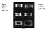
- FIG. 1 aprovides a radiograph of implants of the present invention in comparison to allograft bone.
- FIGS. 1 b and 1 cprovide a radiograph of the present invention material in comparison to other standard materials.
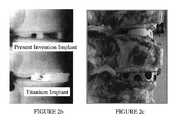
- FIG. 2 aprovides a radiograph of an implant of the present invention after insertion between adjacent vertebrae in a sheep spine
- FIGS. 2 b and 2 cprovide a radiograph and corresponding image, respectively, of a present invention implant (top) in comparison to a titanium implant (bottom) in a calf spine.
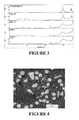
- FIG. 3provides Fourier Transform Infrared Spectroscopy (FTIR) spectrum of the material of the present invention from an in vitro bioactivity test at Day 0, 6, 19 and 50 in comparison to hydroxylapatite.
- FTIRFourier Transform Infrared Spectroscopy
- FIG. 4provides back-scattered electron (BSE) microscopy images of the material of the present invention at Day 0.
- BSEback-scattered electron
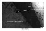
- FIG. 5provides (a) a Scanning Electron Microscopy (SEM) image of a Day 6 sample of the material of the present invention from an in vitro bioactivity test with a layer of calcium phosphate on the surface of a bioactive filler (2500 ⁇ ), (b) SEM of a cross-section of Day 19 with a CaP growth on the surface of a bioactive filler (2500 ⁇ ).
- SEMScanning Electron Microscopy
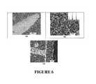
- FIG. 6provides (a) SEM of a Day 50 sample of the material of the present invention with a layer of CaP on its surface (250 ⁇ ), (b) SEM of a Day 50 sample of the material of the present invention with a thick, dense, needlelike growth of CaP on it surface (1000 ⁇ ) (c) SEM of a cross-section of a Day 50 sample of the material of the present invention, CaP has covered the surface and grown into the bioactive filler (1500 ⁇ ).
- FIG. 7provides a cat-scan (CT) image of the implant of the present invention implanted in a non-human primate model at 4 weeks.
- CTcat-scan
- FIG. 8provides a CT image of the implant of the present invention implanted in a non-human primate model at 6 weeks.
- FIGS. 9 a and 9 bprovide histological images of the implant of the present invention implanted in a non-human primate model.
- the present inventionprovides synthetic spinal implant materials that have a radiopacity similar to bone for facilitating radiographic assessment of fusion.
- the implant materials of the present inventionare capable of withstanding physiologic dynamic, compressive loads and is bioactive and biocompatible.
- bioactiverelates to the chemical formation of a calcium phosphate layer via ion exchange between surrounding fluid and the implant materials.
- Bioactivecan also relate to materials that elicits a reaction which leads to bone formation or attachment into or adjacent to implants or to bone formation or apposition directly to the implants usually without intervening fibrous tissue.
- Biocompatible as defined hereinrelates to materials that do not invoke a prolonged adverse immunologic or host response.
- the present inventionalso provides methods for making such implant materials.
- the implant materials of the present inventioncan be comprised of a biocompatible polymeric matrix reinforced or coated with bioactive fillers and fibers.
- the implantscan probably be comprised of a diurethane dimethacrylate (DUDMA) and tri-ethylene glycol dimethacrylate (TEGDMA) blended resin and a plurality of fillers and fibers including bioactive fillers and E-glass fibers.
- the implantsmay also be comprised of a variety of other monomers and fillers as described herein.
- This inventionteaches synthetic, bioactive spinal implant materials having a range of radiopacity from about 30 to about 55 and a range of stiffness from about 6 GPa to about 20 GPa.
- the inventionalso provides a synthetic, artificial shaped bodies in the form of a spinal implant, said implant shaped body having a radiopacity of about 30 to about 55 and a range of stiffness of about 6 GPa to about 20 GPa.
- Another embodimentdiscloses synthetic spinal implant materials that are optimized for radiopacity, stiffness, and bioactivity, comprising: a polymerizable resin matrix of DUDMA and TEGDMA resins and at least one filler.
- the implant materialscan be formed from a polymerized resin matrix and can include at least one filler that can be bioactive.
- a bioactive fillercan comprise combeite.
- the polymerized matrixcan comprise about 20% to about 50% of the total composition of the implant material. Fifty to about 80% of the filler can comprise the total composition of the implant material.
- the radiopacity of the implantscan range from about 38 to about 50. Also, the stiffness can range from about 8 GPa to about 17 GPa.
- Also included are methods of making a synthetic spinal implant material that is optimized for radiopacity, stiffness and bioactivitycomprising: mixing a resin blend of DUDMA and TEGDMA mixing said resin blend with at least one filler, and agitating the to form said implant material.
- the embodiment of this inventioncan be used to form a variety of different orthopaedic implants, particularly spinal implants having various shapes and sizes.
- the present inventionprovides bioactive and biocompatible implant materials for formulation of shaped bodies capable of withstanding large dynamic, compressive loads, especially spinal implants. Further, the implant materials of the present invention overcome the risks associated with disease transmission present with allograft devices. Moreover, the implant materials of the present invention exhibit a radiopacity similar to that of bone.
- the materials of this inventionare preferably comprised of a biocompatible, hardenable polymeric matrix reinforced with bioactive and non-bioactive fillers.
- the materialscan be comprised of about 10% to about 90% by weight of the polymeric matrix and about 10% to about 90% by weight of one or more fillers.
- the materialscan also be comprised of about 20% to about 50% by weight of the polymeric matrix and about 50% to about 80% by weight of one or more fillers.
- the implants of the present inventioncan be comprised of a bioactive material that can comprise a polymeric blended resin reinforced with bioactive ceramic fillers. Examples of such bioactive materials can be found, for example, in U.S. Pat. Nos. 5,681,872 and 5,914,356 and pending application U.S. Ser. No. 60/305,070, which is assigned to the assignee of the present invention and incorporated herein by reference in its entirety.
- the polymeric matrixes of the implant materialsare comprised of polymerizable monomer, monomers, dimers or trimers. They can comprise ethylenically unsaturated monomers or even an acrylate functional group.
- the term “monomers,” as used herein,can also represent dimers, trimers, resins, resin components or any other polymerizable component. Examples of the monomers include, but are not limited to, DUDMA, bisphenol-A-glycidyl methacrylate (bis GMA), TEGDMA, ethoxylated bisphenol-A-dimethacrylate (bis-EMA), or combinations thereof.
- monomers that can be used in the present inventioninclude the adducts of 2,2,3-trimethylhexane diisocyanate with hydroxyethyl methacrylate, hydroxypropyl methacrylate, and other hydroxyacrylic acrylic species can also be used.
- polymerizable speciesthat can be used in the present invention include those disclosed in U.S. Pat. Nos. 5,681,872 and 5,914,356, and pending application U.S. Ser. No. 60/305,070, which are incorporated herein by reference in their entirety.
- Methyl methacrylate, ethyl methacrylate, propyl methacrylate, higher methacrylates, acrylates, ethacrylates, and similar speciescan be employed as all or part of the polymerizable materials of the implant materials of the present invention. It is also possible to employ other types of polymerizable material such as epoxide compounds, polyurethane-precursor species and a wide host of other materials.
- other monomers useful in the production of hardenable compositions of this inventioninclude methyl-, ethyl, isopropyl-, tert-butyloctyl-, dodecyl-, cyclohexyl-, chloromethyl-, tetrachloroethyl-, perfluorooctyl-, hydroxyethyl-, hydroxypropyl-, hydroxybutyl-, 3-hydroxyphenyl-, 4-hydroxphenyl-, aminoethyl-, aminophenyl-, thiophenyl-, acrylate, methacrylate, ethacrylate, propacrylate, butacrylate, and chloromethacrylate, as well as the homologous mono-acrylic acid esters of bisphenol-A, dihydroxydiphenyl sulfone, dihydroxydiphenyl ether, dihydroxybiphenyl, dihydroxydiphenyl sulfoxide, and 2,2 bis(4-hydroxy-2,3,
- Polymerizable monomers capable of sustaining a polymerization reactionsuch as the di-, tri-, and higher acrylic ethylene glycol dimethacrylate, diethylene glycol dimethacrylate, trimethylene glycol dimethacrylate, trimethylol propane trimethacrylate, analogous acrylates and similar species are also useful. It is also possible to employ mixtures of more than two polymerizable species to good effect.
- the implant materials of the present inventioncan further comprise polymeric additives that include, but are not limited to, polymerization inhibitors, polymerization activators, polymerization initiators, stabilizers such as UV-9, radiopacifiers, reinforcing components (i.e., fibers, particles, micro spheres, flakes, etc.), bioactive fillers, neutralizing resins, diluting resins, antibiotic agents, coloring agents, plasticizers, coupling agents, free radical generators, radiographic contrast agents, and antibiotics.
- polymeric additivesinclude, but are not limited to, polymerization inhibitors, polymerization activators, polymerization initiators, stabilizers such as UV-9, radiopacifiers, reinforcing components (i.e., fibers, particles, micro spheres, flakes, etc.), bioactive fillers, neutralizing resins, diluting resins, antibiotic agents, coloring agents, plasticizers, coupling agents, free radical generators, radiographic contrast agents, and antibiotics.
- the implant materialsinclude a monomeric blended resin of DUDMA to impart strength, TEDGMA to impart flexibility, a benzoyl peroxide initiator (BPO) or any peroxide initiator that is consumed during the polymerization reaction, and at least one polymer stabilizer.
- the implant materialscan also include a plurality of fillers and fibers.
- the fillerscan be of the combeite type, such as the combeite filler described in U.S. Pat. No. 5,681,872 to render the material bioactive and encourage direct bone bonding.
- the fillercan be selected from a group of fillers including, but not limited to, borosilicate, silica, Wollastonite, hydroxyapatite (HA), beta-tricalcium phosphate, calcium sulfate, alumina, and the like.
- the fiberscan further include E-glass fibers of the composition type [SiO 2 CaO Al 2 O 3 B 2 O 3 , A-glass fibers, silica or a plurality of other fibers including but not limited to Kevlar and carbon fibers for imparting toughness and strength to the implant.
- the fillers and fibersare surface treated for incorporation and bonding between them and the resin.
- the fillers and fiberscan be silanated, silicone-oil treated, or provided with coupling agents such alumina, titania, or zirconia coupling agents.
- radiopacityis calculated as an optical density ratio of the material versus an aluminum standard of the same thickness, both of which are normalized by the background sample optical density. The resultant number is multiplied by 100 and then referred to as the percent relative linear attenuation coefficient, ⁇ , which is dimensionless.
- embodiments of the present inventionare synthetic, bioactive spinal implant materials having a radiopacity between about 30 to about 55 and stiffness between about 6 GPa to about 20 GPa.
- Other embodimentsprovide a synthetic, artificial shaped body in the form of a spinal implant, said shaped body having a radiopacity of about 30 to about 55 and a stiffness of about 6 GPa to about 20 GPa.
- the radiopacity of boneranges between about 24 to about 52 as reported by Brantigan, et al., “Compression Strength of Donor Bone for Posterior Interbody Fusion,” Spine , 18, 1213-1221 (1983), with a stiffness ranging from about 3 GPa to about 17 GPa. Similar to bone, which is naturally bioactive, the present inventions also display bioactivity.
- the spinal implant materialscan have a radiopacity of about 30 to 55 and a range of stiffness of about 8 GPa to 17 GPa.
- the spinal implantcan be formed from a polymerized resin matrix. At least one filler can be included in other embodiments and any of the fillers can be bioactive.
- the bioactive fillercan be combeite glass ceramic or another type of ceramic filler.
- the polymerized resin matrixcomprises about 20% to about 50% of the total composition of the implant material. About 50% to about 80% of the total composition of the implant material can be filler.
- Certain embodimentsare synthetic spinal implant materials that are optimized for radiopacity, stiffness, and bioactivity, comprising a polymerizable resin matrix of DUDMA and TEGDMA resins and at least one filler.
- the present invention materialhas been described in terms of polymeric matrices comprised of polymerizable monomers and the like, it should be understood that the disclosed radiopacity and stiffness ranges may be achieved by using a variety of materials.
- the polymeric matrixmay be composed of any polymeric material and include an additional organic or inorganic component.
- the matrixmay be thermoplastic, thermoset, polymerizable, or non-polymerizable.
- Epoxiespolyurethanes, polyphosphates, polyesters, polyamides, polyphosphazenes, polycarbonates, polyureas, polyamides, polyacrylonitriles, polysulfones, polysulfides, polysiloxanes, polyacetals, polyethers such as polyetheretherketone (PEEK), fluoropolymers, polyketals, polyolefins such as polyethylene (PE), polypropylene (PP), polystyrene, and polyvinylchloride (PVC), and the like may also be used. These materials may be used either alone, in combination, or with various fillers to form a copolymer or terpolymer with the present invention to provide an implant material that yields desired radiopacity and stiffness comparable to bone as described herein.
- the resin blendcan also comprise an initiator. Both mixing steps can occur under vacuum.
- the fillerscan be added in the range of about 15% by weight to about 80% by weight of the total mixture composition. If vacuum is applied at this stage, it can be applied upon the addition of each filler. Agitation of the resultant mixture can be added to further eliminate bubbles or voids.
- the monomers, fillers, and other additivesare blended together to form a paste composition.
- the paste compositionsare easily mixed via a low speed, high shear rotary mixer.
- the duration of the blending operationwill vary depending upon the constituents that comprise the paste composition precursors.
- the blending of the monomers and other additives within the paste composition precursorsactivates the polymerization of the composition.
- exposure to heat either during or after blendingactivates the polymerization. The exposure can occur in temperature ranges of about 40° C. to about 180° C. or about 60° C. to about 120° C. in some instances.
- the implant materials of the present inventioncan be comprised of a one paste system or combined with two or more paste compositions to form a multiple paste system. Depending upon whether the implant material is a one paste or multiple paste system determines the hardening of the material.
- the paste compositions of the present inventioncan be hardened under the influence of heat, photochemical energy, chemically, or in a controlled fashion.
- the paste compositionis hardened or cured via exposure to heat or light.
- the paste compositioncould be cured via gamma radiation.
- additional exposure to gamma radiationcan impart additional strength.
- the paste compositionsare admixed and hardened via thermal energy or heat cured.
- the paste compositionscan also be chemically cured via catalyst or redox systems. It will be understood, however, that a wide variety of polymerization systems and materials for use therein can be employed to good advantage in connection with the present invention and all such systems are contemplated hereby.
- the paste compositioncan generally comprise heat-curing catalysts, photopolymerization, or redox (i.e. N,N(dihydroxyethyl)-p-toluidine(DHEPT), BPO, FeII, tertiary butyl hydroperoxide (t-BHP)) initiators. Each type is well-known and any catalytic system known for restorative use can be employed so long as the same is consistent with the objects of the invention.
- a catalytic systemis employed such that when two components of the hardenable composition are mixed together, the catalytic action begins, leading to hardening.
- This systemis familiar and can be applied to a wide variety of polymerizable species including many which are suitable in the present invention. Radical initiators such as peroxides, especially benzoyl peroxide (also called dibenzoyl peroxide) are conventional, economic and convenient.
- a stabilizer such as butyl hydroxy tolueneis customary, as is employment of co-catalysts like dimethyl-p-toluidine, N-N-substituted toluidine, and other conventional catalysts including tertiary amine structures with double bond functionality like diethyl aminoethyl methacrylate and N,N-dimethyl-p-toluidine.
- one of the pastesincorporates both the radical initiator and stabilizer, such as a peroxide, and the other paste incorporates the accelerator, such as an amine or toluidine. Curing is initiated by an oxidation-reduction mechanism upon mixing the two pastes together.
- a photoinitiation systemcan be included with the hardenable compositions and the same caused to be activated by exposure to actinic light of a suitable wavelength.
- ultraviolet and visible photocuring systemsare known for use in restorative surgery and dentistry and any such system can be employed herein. Exemplary systems are described in U.S. Pat. No. 4,110,184 to Dart et al., U.S. Pat. No. 4,698,373 to Tateosian et al., U.S. Pat. No. 4,491,453 to Koblitz et al., and U.S. Pat. No. 4,801,528 to Bennett, which are incorporated herein by reference in their entirety to provide enablement for such, known systems.
- a particularly useful systememploys visible light curing, thus avoiding the potential danger inherent in curing with ultraviolet radiation. Visible light curing has been well refined in the dental field and the same can also be applied to restorations of bony tissues.
- Quinonesas a class, find wide utility as photochemical initiators for visible light sensitizing systems, preferably when the same are admixed with tertiary amines.
- Some skilled artisansmay prefer that an alpha diketone (quinone) such as camphoroquinone or biacetyl be admixed with an amine reducing agent such as n-alkyl dialkanolamine or trialkanolamine.
- photo-initiator systemsinclude a 2-Benzyl-2-(dimethylamino)-4′-morpholinobutyrophenone, or 50%/50% weight composition of 2-Hydroxyethyl-2-methyl-1-phenyl-1-propanone and Diphenyl (2,4,6-trimethylbenzyl) phosphine oxide.
- other such curing systems or combinations of curing systemscan also be employed with the materials of the present invention.
- the paste systemis not cured or hardened but used in situations in which the paste form is preferred. In those cases, the paste may be dispensed from a tube or the like.
- one or more fillersare blended into the paste composition after the monomers and other additives comprising the resin blend have been combined. The fillers can be added incrementally to avoid binding during the blending process. A vacuum can be applied during blending to minimize porosity and dusting.
- Some embodimentscomprise multiple fillers, which may include E-glass fibers and fillers or fibers of borosilicate, silica, and combeite. In particular embodiments, the E-glass fibers can be added first followed by the remaining fillers in a designated order.
- one or more fillerscan be pre-blended together prior to incorporation into the resin blend.
- the completed paste mixturecan be agitated via a vibrating table, ultrasonic or similar means for a period of time ranging from about 5 minutes to about 60 minutes to further reduce porosity.
- a vacuumcan be applied during the agitation step.
- Table Ishows a number of compositions in accordance with certain preferred embodiments of the present invention together with salient data showing suitability for orthopaedic, especially spine implant use.
- Six exemplary implant materialswere made in accordance with the present invention. The weight percentage of each composition is presented in the table. As the following table illustrates, the Examples 2-4 are multiple paste systems wherein Examples 5-7 are one paste systems.
- the implant materials of Examples 2-7can be fashioned into standard shapes, which include cylinders, bricks, and dog bones, for testing.
- the compressive strength, compressive yield, and compressive moduluswere tested, as were the tensile strength and tensile modulus.
- Compressive testingwas conducted in accordance with ASTM D 695-91 using 6 mm diameter ⁇ 12 mm height cylindrical specimens.
- Tensile testingwas conducted in accordance with ASTM D 638-95, using Type IV specimen geometry of flat tensile bars or “dog bone”.
- radiopacitywas conducted in accordance with ASTM F 640-79 (“Radiopacity of Plastics for Medical Use”).
- the implants of the present inventioncan have use as dental crowns (temporary or crown) and dental implants, including Maryland bridges.
- the implant materialscan also have use as implants for other areas of the animal body.
- Such foreseeable implantsinclude cochlear, cranial, tumor, sternum, or other custom implants that can be MRI compatible or functional shapes made for the body.
- TMJmandibular joints
- orbital reconstructionOther pharmaceutical uses include non-articulating artificial joint surfaces, sensor anchors or housings, bone spacers or wedges (tibial, femoral), cartilage beds or anchors, or drug delivery. It is also foreseeable that the implant materials can be used in methods for repairing the iliac harvest site. The materials can be incorporated into drug delivery beads into bone or in interbody balls. There can also be applications for mandibular joints (TMJ) and orbital reconstruction.
- TMJmandibular joints
- One embodiment of the present inventioninvolves machining of the implantable materials into morsels for use in methods to treat segmental defects.
- the morselscan also be used for minimally invasive load bearing applications.
- the materialcan be made into a mesh for postero-lateral fusion or cages for other materials.
- Other embodimentsinvolve the material being used as a cannulated screw with peripheral holes used in methods for treating vertebral augmentation.
- the present inventioncan have embodiments involving synthetic bones.
- An exemplary implant material for the manufacture of spinal implants in accordance with the inventionwas formulated to exhibit biocompatibility and bioactivity for bone bonding, radiopacity similar to bone in order to be able to assess fusion, mechanical strength to support physiologic loads, and bone-like stiffness to allow for good load sharing among the elements of the spine.
- One implant materialincludes a polymeric blended resin, comprising 20% to about 50% by weight of the implant material total composition.
- the resin blendcan be further comprised of from about 30% to about 90% by weight of resin DUDMA, about 10% to about 60% by weight of resin TEGDMA, about 0.1% to about 4% by weight of BPO, and 0% to about 0.25% by weight of butylated hydroxy toluene (BHT).
- BHTbutylated hydroxy toluene
- the remainder of the implant materialis comprised of a plurality of fillers.
- the fillerscan be further comprised of from about 0% to about 40% by weight of filler surface treated E-glass® fibers to impart fracture toughness and mechanical strength and having have an average length of about 3000 ⁇ m or less and an average diameter range of about 5 ⁇ m to 50 ⁇ m; about 5% to about 50% by weight of filler surface treated, silanated combeite filler having bioactive characteristics which promote bone bonding; about 0% to about 50% by weight of filler of a surface treated borosilicate glass filler having an average diameter of ⁇ 10 ⁇ m (e.g., 90% of the particles have a diameter of less than 10 ⁇ m, measured by laser analysis); and about 0% to about 30% by weight of filler of a surface treated silica for imparting mechanical strength and to act as a rheology modifier.
- the filleris comprised of about 20% by weight surface treated E-glass® fibers, about 20% by weight of filler surface treated, silanated combeite filler, about 23% by weight of filler of a surface treated borosilicate glass filler, and about 5% by weight of filler is surface treated silica.
- Material of the present inventionwas prepared in the shape of an implant, which was placed along side an allograft implant for qualitative radiographic assessment as shown in FIG. 1 a . Visually the samples had a similar radiographic appearance. In comparison to standard materials ( FIG. 1 b ), the radiographic appearance of the material of the present invention most closely resembles bone. Variations of the present invention material can be formulated to produce variations in radiopacity as shown in FIG. 1 c.
- the lowest stage in the Faxitron cabinetwas used and its focus-film distance was 50 mm.
- the 4-mm thick sampleswere exposed using appropriate exposure time and voltage (180 sec., 80 kVp).
- a background optical density ranging from 0.8 to 1.2defined an appropriate exposure.
- the materialafter gamma irradiation, had an average radiopacity value of 42.94.
- Radiopacity of polymerized material for medical useis clinically important due to the frequency of using x-rays in measuring the placement, function, form, and effectiveness of the material.
- Both pre and post gamma bioactive implantshave a radiopacity value that will allow for good radiographic viewing that will aid in the placement and postoperative monitoring of spinal implants made from this material.
- Radiopacity values for the bioactive spinal implant material of the present inventioncompare favorably with human bone, which has a radiopacity range of about between 24 to 52.
- the radiopacity of the material of the present inventionallows for visualization of the implant between adjacent vertebral bodies (in this case in a segment of a sheep spine), as well as visualization for the eventual assessment of fusion from a medial-lateral radiograph. This observation is also noted in FIGS. 2 b and 2 c in comparison to a titanium implant.
- Sampleswere prepared using the bioactive material described herein. Tests were performed using ASTM Guidelines on an Instron Model 8516 in order to obtain ranges of values of mechanical properties of the material as shown in the table below.
- Bioactivity testingwas performed on disc shaped implants comprised of the material described herein. Bioactivity as used throughout this disclosure is defined as the ability of the implant to form a calcium phosphate layer on its surface.
- FTIRFourier Transform Infrared Spectroscopy
- the sampleswere analyzed using the Nicolet Instruments Magna 560 FTIR.
- the stage used for this analysiswas a single-bounce Attenuated Total Reflectance (ATR) with a diamond crystal and KRS-5 lenses. This stage permitted a surface analysis of the composites through the entire mid-infrared spectrum from 4000 to 400 cm-1.
- the sampleswere analyzed at a 4 cm-1 resolution.
- the sampleswere placed in direct contact with the ATR crystal. Contact was maximized via an anvil on the opposite side of the sample.
- Spectrawere collected on several areas of the composite samples. At each time point, spectra were analyzed for the presence of key calcium phosphate bands as compared to the Day 0 control.
- the characterization of bioactivity of the polymerized composite surface by scanning electron microscopyconsisted of the following parameters: appearance of calcium phosphate deposition (white in back-scattered electron imaging “BSEI” mode) and thickness of calcium phosphate layer.
- the characterization of bioactivity of the polymerized composite surface by energy dispersive spectroscopyconsisted of the following parameters: calcium and phosphorous detection and reduction in sodium levels at a bioactive filler.
- Rhakoss FTIR resultsare shown in FIG. 3 .
- the displayed resultsshow few spectral changes are observed in the early time periods.
- the Day 50 spectrumdemonstrates dramatic changes and is very similar to hydroxyapatite.
- the Day 50 resultsshow the maturity of the calcium phosphate growing on the material. Note the sharpness of the 1014 cm-1 band in Day 50 spectra.
- FIG. 4Day 0 back-scattered electron (BSE) image of a cross-section of the material is illustrated in FIG. 4 (500 ⁇ ).
- the materialdemonstrated a calcium phosphate crystal (CaP) as early as 6 days as confirmed by EDS analysis.
- the Day 6 sampleshowed the growth was limited to a few bioactive fillers.
- the Day 19 sampleshowed little differences from the earlier time period as demonstrated in FIG. 5 .
- FIG. 6illustrates the CaP crystal on the surface of Rhakoss.
- the Day 50 spectrawere compared against several types of calcium phosphates in the User library.
- the best spectral match for both sampleswas hydroxyapatite. This close match indicates that hydroxyapatite is the calcium phosphate species growing on the sample surface.
- the primary hydroxyapatite band seenoccurs around 1014 cm-1. This band demonstrates a more resolved hydroxyapatite shoulder at 955 cm-1, pointing to a mature species.
- the materialappears to have a larger surface coverage of calcium phosphate and a thickness of CaP deposition.
- the evaluations of the cross-sectioned samplesprovided an accurate measurement of the CaP thickness.
- he CaP layerwas evaluated for its interdigitation into the composite. Several observations of the CaP migrating into a bioactive E-glass ceramic filler at the surface were noted.
- the material of the present inventioncan be described as bioactive.
- Static compressionwas performed on 6 spinal implants with a 7° lordotic angle. All implants withstood at least 8.1 kN of axial load before yielding. In compression-shear testing, the weakest implant type (6 mm extra wide) had a yield of approximately 2.7 kN. Note that human cervical endplates fail at 2.0 kN direct compression.
- Implant failureoccurred at approximately 41 kN (about 9000 lbf), approximately 12 times body weight.
- the aorta, vena cava and bifurcation of the left and right common iliac vesselswere dissected for free mobility overlying the spine.
- Middle sacral artery and venous branchwere ligated.
- the vesselswere retracted with blunt retractors to allow direct approach to the ventral aspect of the lumbar spine.
- a marker probewas placed in position and a lateral x-ray was obtained to confirm the appropriate level of disc. After confirmation of level, the probe was removed and a complete discectomy was performed.
- the anterior longitudinal ligamentwas cut away as well as anterior annulus material. The disc was then removed in total.
- the bony endplateswere cleaned and penetrated so that there was vascular blood flow across the endplate.
- the disc spacewas distracted using a distracter instrument.
- Two bioactive spinal implantswere placed into the distracted disc space, and carefully impacted.
- a calcium phosphate/bone marrow aspirate (BMA) bone graft materialwas packed around and between the implants in the disc space.
- the dynamic DOCTM Ventral Cervical Stabilization System(DePuy Acromed, Raynham, Mass.) was placed ventrally to prevent hyperextension of the motion segment and subsequent dislodgment or migration of the implant devices. Following placement, the vessels were allowed to return to their normal position. The posterior peritoneal sheath was then closed with running absorbable suture. The bowel content was allowed to go back into position followed by standard closure of the ventral abdominal wall, the midline fascia, and the skin with subcuticular absorbable suture material.
- the rate and quality of healingwere assessed using radiographs and CT scans taken at 1, 2, 3, and 6 months (FIGS. 7 & 8 ).
- micewere anesthetized (induction by ketamine (10-15 mg/kg BW IM), and, at the discretion of the attending veterinarian, diazepam (10 mg, IM) or acepromazine (1.0 mg/kg, IM) and then euthanized. Following euthanasia, the lumbar spine was retrieved en bloc and the specimens were photographed and observed grossly.
- the excised spinal specimenswere inspected for successful fusion and structural integrity of each motion segment.
- the DOCTM systemwas removed and the cranial segments were separated from the caudal segments and the specimens photographed and observed grossly.
- Specimens without sufficient structural integrity for mechanical testingwere immediately prepared for histologic evaluation. Those with sufficient structural integrity were mechanical tested and then prepared for histological evaluation.
- a resin blend(about 20% to about 50% of total implant composition) of DUDMA, TEGDMA, initiator and stabilizer were poured into a Ross planetary mixing system (Hauppauge, N.Y.). The mixer was sealed, mixing was commenced and a vacuum was applied for approximately 15 minutes to about 30 minutes. After the mixer was turned off and the vacuum released, one or more fillers (about 15% to about 80% of the total implant composition) such as E-glass fibers, borosilicate fillers, silica fillers, and combeite fillers were added. Mixing was commenced and a vacuum was drawn for approximately 15 minutes to about 30 minutes upon the addition of each increment of filler. Once all of the fillers were incorporated into the resin, a vacuum was drawn for an additional 20 minutes. The mixture was then agitated on a vibrating table with vacuum for about 5 minutes to 60 minutes. The material was extruded into a mold cavity for molding into various bulk geometries.
- the mold cavitieswere heated in a Despatch LFD Series oven and cured at about 40° C. to about 180° C. for a time duration of about 1 hour to 20 hours to form a molded body.
- Various shaped bodies or implant bodieswere then formed.
- the materialscan also be hot extruded, injection molded, compression molded, or reacted in a mold with a catalyst other than heat.
- the cylindrical stockwas machined at MedSource (Laconia, N.H.) into spinal implants of the various shapes disclosed herein, having a generally anatomical shape with convex superior and inferior surfaces, lordotic angles, and the like.
Landscapes
- Health & Medical Sciences (AREA)
- Chemical & Material Sciences (AREA)
- Epidemiology (AREA)
- Life Sciences & Earth Sciences (AREA)
- Veterinary Medicine (AREA)
- Public Health (AREA)
- General Health & Medical Sciences (AREA)
- Animal Behavior & Ethology (AREA)
- Oral & Maxillofacial Surgery (AREA)
- Medicinal Chemistry (AREA)
- Transplantation (AREA)
- Dermatology (AREA)
- Materials Engineering (AREA)
- Composite Materials (AREA)
- Engineering & Computer Science (AREA)
- Inorganic Chemistry (AREA)
- Physics & Mathematics (AREA)
- Optics & Photonics (AREA)
- Heart & Thoracic Surgery (AREA)
- Surgery (AREA)
- Vascular Medicine (AREA)
- Prostheses (AREA)
- Materials For Medical Uses (AREA)
Abstract
Description
| TABLE I |
| Comparison |
| Ex. 2 | Ex. 3 | Ex. 4 | Ex. 5 | Ex. 6 | Ex. 7 | ||
| Formulation Comparison | ||||||
| [Product (%)] | ||||||
| Bis-GMA | 12-14 | 13-15 | 0-1 | 0-1 | 0-1 | 0-1 |
| Bis-EMA | 5-7 | 6-8 | 0-1 | 0-1 | 0-1 | 0-1 |
| TEGDMA | 11-13 | 12-14 | 8-10 | 7-9 | 7-9 | 7-9 |
| DUDMA | 0-1 | 0-1 | 24-28 | 24-28 | 24-28 | 24-28 |
| t-Butylhydroxytoluene | 0-1 | 0-1 | 0-1 | 0-1 | 0-1 | 0-1 |
| DHEPT | 0-1 | 0-1 | 0-1 | 0-1 | 0-1 | 0-1 |
| UV-9 (C14H12O3) | 0-1 | 0-1 | 0-1 | 0-1 | 0-1 | 0-1 |
| BPO | 0-1 | 0-1 | 0-1 | 0-1 | 0-1 | 0-1 |
| Silane Treated Amorphous | 7-9 | 6-8 | 6-8 | 4-6 | 4-6 | 4-6 |
| Silica | ||||||
| Silane Treated Orthovita | 28-31 | 18-21 | 18-21 | 20-23 | 22-24 | 19-21 |
| Combeite [OC] Filler | ||||||
| Silane Treated | ||||||
| Bariaboroaluminosilicate | 29-32 | 0-1 | 0-1 | 0-1 | 0-1 | 0-1 |
| Glass | ||||||
| Silane Treated Alkali Leached | 0-1 | 16-19 | 16-19 | 20-23 | 19-21 | 0-1 |
| OC Filler | ||||||
| Silane Treated E-Glass | 0-1 | 19-21 | 19-21 | 19-21 | 19-21 | 19-21 |
| Silane Treated Borosilicate | 0-1 | 0-1 | 0-1 | 0-1 | 0-1 | 22-24 |
| Filler | ||||||
| Approx. Test Parameter | ||||||
| before Gamma Irradiation | ||||||
| Compressive Strength (MPa) | 211 | — | — | 195.6 | 216.3 | 238.4 |
| Compressive Yield (MPa) | 127 | 105 | 125 | 150 | 170 | 182 |
| Compressive Modulus (MPa) | 5800 | 6998 | 7875 | 8456 | 8403 | 8516 |
| Tensile Strength (MPa) | 52.5 | 60.2 | 54.3 | — | 63.4 | 86.7 |
| Tensile Modulus (MPa) | 9800 | 10306 | 11976 | — | 14839 | 16290 |
| Radiopacity | 118.6 | — | 50 | — | 46.3 | 57.3 |
where:
- B=background optical density of 10 mm of Al, in the range of 0.8 to 1.2.
- A=optical density under the 14 mm thickness of Al (4 mm Al sample added to 10 mm Al background), and
- S=optical density of the image of the 4 mm thick sample.
Results
| TABLE II |
| Optical density values for three lots of |
| material prior to gamma irradiation. |
| Linear | |||||
| attenuation | |||||
| Back- | Sample, | Aluminum, | coefficient, | ||
| Lot Number | Sample | ground, B | S | A | α |
| 022601-067 | 1 | 0.89 | 0.76 | 0.58 | 41.94 |
| 2 | 0.86 | 0.73 | 0.57 | 44.83 | |
| 3 | 0.92 | 0.78 | 0.61 | 45.16 |
| Mean | 0.89 | 0.76 | 0.59 | 43.98 |
| S.D. | 0.03 | 0.03 | 0.02 | 1.77 |
| 022601-074 | 1 | 0.92 | 0.78 | 0.61 | 45.16 |
| 2 | 0.83 | 0.71 | 0.55 | 42.86 | |
| 3 | 0.93 | 0.78 | 0.60 | 45.45 |
| Mean | 0.89 | 0.76 | 0.59 | 44.49 |
| S.D. | 0.06 | 0.04 | 0.03 | 1.42 |
| 032601-082 | 1 | 0.92 | 0.78 | 0.60 | 43.75 |
| 2 | 0.91 | 0.77 | 0.66 | 56.00 | |
| 3 | 0.85 | 0.72 | 0.56 | 44.83 |
| Mean | 0.89 | 0.76 | 0.61 | 48.19 |
| S.D. | 0.04 | 0.03 | 0.05 | 6.78 |
| 022601-067 | Mean | 0.89 | 0.76 | 0.59 | 43.98 |
| 022601-074 | Mean | 0.89 | 0.76 | 0.59 | 44.49 |
| 032601-082 | Mean | 0.89 | 0.76 | 0.61 | 48.19 |
| Mean | 0.89 | 0.76 | 0.60 | 45.55 |
| S.D. | 0.00 | 0.00 | 0.01 | 2.30 |
| TABLE III |
| Optical density values for three lots of material after gamma irradiation |
| Linear | |||||
| attenuation | |||||
| Back- | Sample, | Aluminum, | coefficient, | ||
| Lot Number | Sample | ground, B | S | A | α |
| 022601-067 | 1 | 1.01 | 0.85 | 0.62 | 41.03 |
| 2 | 0.99 | 0.84 | 0.63 | 41.67 | |
| 3 | 1.05 | 0.89 | 0.68 | 43.24 |
| Mean | 1.02 | 0.86 | 0.64 | 41.98 |
| S.D. | 0.03 | 0.03 | 0.03 | 1.14 |
| 022601-074 | 1 | 1.01 | 0.85 | 0.64 | 43.24 |
| 2 | 1.00 | 0.84 | 0.62 | 42.11 | |
| 3 | 1.01 | 0.85 | 0.64 | 43.24 |
| Mean | 1.01 | 0.85 | 0.63 | 42.86 |
| S.D. | 0.01 | 0.01 | 0.01 | 0.66 |
| 032601-082 | 1 | 0.99 | 0.84 | 0.63 | 41.67 |
| 2 | 0.98 | 0.83 | 0.62 | 41.67 | |
| 3 | 1.01 | 0.83 | 0.64 | 48.65 |
| Mean | 0.99 | 0.83 | 0.63 | 43.99 |
| S.D. | 0.02 | 0.01 | 0.01 | 4.03 |
| 022601-067 | Mean | 1.02 | 0.86 | 0.64 | 41.98 |
| 022601-074 | Mean | 1.01 | 0.85 | 0.63 | 42.86 |
| 032601-082 | Mean | 0.99 | 0.83 | 0.63 | 43.99 |
| Mean | 1.01 | 0.85 | 0.63 | 42.94 |
| S.D. | 0.02 | 0.02 | 0.01 | 1.01 |
Conclusions
| TABLE IV |
| Mechanical Properties of a Bioactive Spinal Implant Material |
| HUMAN CORTICAL | ||
| TEST | RESULT | BONE LITERATURE |
| Compressive Strength | 220-250 | MPa | 167-215 | MPa |
| ASTM F 451-95 & ASTM | ||||
| D695-91 | ||||
| Compressive Modulus | 7.0-9.0 | GPa | 14.7-19.7 | MPa |
| ASTM F 451-95 & ASTM | ||||
| D695-91 | ||||
| Compressive Yield Strength | 170-182 | MPa | 121-182 | MPa |
| ASTM F 451-95 & ASTM | ||||
| D695-91 | ||||
| Tensile Strength | 65-100 | MPa | 70-140 | MPa |
| ASTM D638-98 | ||||
| Tensile Elastic Modulus | 14-17 | GPa | 10.9-14.8 | MPa |
| ASTM D638-98 | ||||
| 3-Point Flexural Strength | 100-120 | MPa | 103-238 | MPa |
| ASTM D790-90 | ||||
| Shear by Punch Tool | 60-80 | MPa | 51.6 | MPa |
| ASTM D732-93 | ||||
| Compressive Fatigue Strength | 170-190 | MPa | >100 | MPa |
| (106cycles) | ||||
| Tensile Fatigue Strength | 35-55 | MPa | 49 | MPa |
| (106cycles) | ||||
| TABLE V |
| FTIR Peaks of the Material of the |
| Present Invention and Hydroxyapatite |
| ABSORBANCE BAND | |
| (cm−1) |
| HYDROXYAPATITE | RHAKOSS | MOLECULAR ASSIGNMENT |
| — | 3292 | O—H and hydrogen bonding from |
| residual water on the composite | ||
| — | 1632 | Olefin stretch from the composite |
| 1092 | 1075 | Three components of the out of |
| 1014 | 1014 | phase stretch of the phosphate ion |
| 956 | 960 | |
| — | — | Possibly an out of phase |
| deformation band of a carbonate | ||
| ion resulting from residual SBF | ||
| salt | ||
| 602 | 598 | A split bending mode of the |
| 559 | 556 | phosphate ion |
SEM/EDS Results
Claims (21)
Priority Applications (5)
| Application Number | Priority Date | Filing Date | Title |
|---|---|---|---|
| US10/127,947US6987136B2 (en) | 2001-07-13 | 2002-04-23 | Bioactive spinal implant material and method of manufacture thereof |
| MXPA04000359AMXPA04000359A (en) | 2001-07-13 | 2002-07-01 | Bioactive spinal implant material and method of manufacture thereof. |
| EP02749739AEP1408883A1 (en) | 2001-07-13 | 2002-07-01 | Bioactive spinal implant material and method of manufacture thereof |
| CA2454174ACA2454174C (en) | 2001-07-13 | 2002-07-01 | Bioactive spinal implant material and method of manufacture thereof |
| PCT/US2002/020887WO2003005937A1 (en) | 2001-07-13 | 2002-07-01 | Bioactive spinal implant material and method of manufacture thereof |
Applications Claiming Priority (3)
| Application Number | Priority Date | Filing Date | Title |
|---|---|---|---|
| US30507001P | 2001-07-13 | 2001-07-13 | |
| US33987101P | 2001-12-12 | 2001-12-12 | |
| US10/127,947US6987136B2 (en) | 2001-07-13 | 2002-04-23 | Bioactive spinal implant material and method of manufacture thereof |
Publications (2)
| Publication Number | Publication Date |
|---|---|
| US20030087984A1 US20030087984A1 (en) | 2003-05-08 |
| US6987136B2true US6987136B2 (en) | 2006-01-17 |
Family
ID=27383641
Family Applications (1)
| Application Number | Title | Priority Date | Filing Date |
|---|---|---|---|
| US10/127,947Expired - Fee RelatedUS6987136B2 (en) | 2001-07-13 | 2002-04-23 | Bioactive spinal implant material and method of manufacture thereof |
Country Status (5)
| Country | Link |
|---|---|
| US (1) | US6987136B2 (en) |
| EP (1) | EP1408883A1 (en) |
| CA (1) | CA2454174C (en) |
| MX (1) | MXPA04000359A (en) |
| WO (1) | WO2003005937A1 (en) |
Cited By (36)
| Publication number | Priority date | Publication date | Assignee | Title |
|---|---|---|---|---|
| US20040082961A1 (en)* | 2000-06-23 | 2004-04-29 | Teitelbaum George P. | Percutaneous vertebral fusion system |
| US20050112186A1 (en)* | 2003-10-29 | 2005-05-26 | David Devore | Polymerizable emulsions for tissue engineering |
| US20050251140A1 (en)* | 2000-06-23 | 2005-11-10 | Shaolian Samuel M | Formed in place fixation system with thermal acceleration |
| US20060167550A1 (en)* | 2002-10-08 | 2006-07-27 | Robert Snell | High precision manufacture of polyurethane products such as spinal disc implants having a gradual modulus variation |
| US20070032872A1 (en)* | 2002-10-21 | 2007-02-08 | Warsaw Orthopedic, Inc. (Successor in interest to SDGI Holdings, Inc.) | Systems and techniques for restoring and maintaining intervertebral anatomy |
| US20070032568A1 (en)* | 2005-08-08 | 2007-02-08 | Angstrom Medica | Cement products and methods of making and using the same |
| US20070276492A1 (en)* | 2006-05-09 | 2007-11-29 | Ranier Limited | Artificial spinal disc implant |
| US20070293948A1 (en)* | 2001-12-12 | 2007-12-20 | Vita Special Purpose Corporation | Bioactive Spinal Implants and Method of Manufacture Thereof |
| US20080154367A1 (en)* | 2006-12-21 | 2008-06-26 | Warsaw Orthopedic, Inc. | Methods for positioning a load-bearing component of an orthopedic implant device by inserting a malleable device that hardens in vivo |
| US20080154368A1 (en)* | 2006-12-21 | 2008-06-26 | Warsaw Orthopedic, Inc. | Curable orthopedic implant devices configured to harden after placement in vivo by application of a cure-initiating energy before insertion |
| US20080154373A1 (en)* | 2006-12-21 | 2008-06-26 | Warsaw Orthopedic, Inc. | Curable orthopedic implant devices configured to be hardened after placement in vivo |
| US20080154266A1 (en)* | 2006-12-21 | 2008-06-26 | Warsaw Orthopedic, Inc. | Methods for positioning a load-bearing orthopedic implant device in vivo |
| US20080206297A1 (en)* | 2007-02-28 | 2008-08-28 | Roeder Ryan K | Porous composite biomaterials and related methods |
| US20090254182A1 (en)* | 2008-04-02 | 2009-10-08 | John Kovarik | Intervertebral implant devices for supporting vertebrae and devices and methods for insertion thereof |
| US20090270527A1 (en)* | 2007-08-28 | 2009-10-29 | Angstrom Medica | Cement products and methods of making and using the same |
| US20090270988A1 (en)* | 2008-04-24 | 2009-10-29 | Ranier Limited | Artificial spinal disc implant |
| US20100129416A1 (en)* | 2006-09-25 | 2010-05-27 | Orthovita, Inc | Bioactive load-bearing composites |
| US20100168798A1 (en)* | 2008-12-30 | 2010-07-01 | Clineff Theodore D | Bioactive composites of polymer and glass and method for making same |
| US7833249B2 (en) | 2000-06-23 | 2010-11-16 | Warsaw Orthopedic, Inc. | Formable orthopedic fixation system |
| US20110022173A1 (en)* | 2009-07-24 | 2011-01-27 | Warsaw Orthopedic, Inc. | Implant with an interference fit fastener |
| US8303967B2 (en) | 2006-06-29 | 2012-11-06 | Orthovita, Inc. | Bioactive bone graft substitute |
| US8337556B2 (en) | 2000-06-23 | 2012-12-25 | Sdgi Holdings, Inc. | Curable media for implantable medical device |
| US8454694B2 (en) | 2011-03-03 | 2013-06-04 | Warsaw Orthopedic, Inc. | Interbody device and plate for spinal stabilization and instruments for positioning same |
| US8480747B2 (en) | 2010-08-11 | 2013-07-09 | Warsaw Orthopedic, Inc. | Interbody spinal implants with extravertebral support plates |
| WO2013116057A1 (en) | 2012-02-03 | 2013-08-08 | Orthovita, Inc. | Bioactive antibacterial bone graft materials containing silver |
| US8685429B2 (en) | 1999-08-13 | 2014-04-01 | Orthovita, Inc. | Shaped bodies and methods for their production and use |
| US8765189B2 (en) | 2011-05-13 | 2014-07-01 | Howmedica Osteonic Corp. | Organophosphorous and multivalent metal compound compositions and methods |
| US8778378B2 (en) | 2009-12-21 | 2014-07-15 | Orthovita, Inc. | Bioactive antibacterial bone graft materials |
| US9220595B2 (en) | 2004-06-23 | 2015-12-29 | Orthovita, Inc. | Shapeable bone graft substitute and instruments for delivery thereof |
| US9265857B2 (en) | 2010-05-11 | 2016-02-23 | Howmedica Osteonics Corp. | Organophosphorous, multivalent metal compounds, and polymer adhesive interpenetrating network compositions and methods |
| US10092675B1 (en)* | 2017-08-12 | 2018-10-09 | Dewey M Sims, Jr. | Wear-resistant joint arthroplasty implant devices |
| USD907771S1 (en) | 2017-10-09 | 2021-01-12 | Pioneer Surgical Technology, Inc. | Intervertebral implant |
| US11147903B2 (en) | 2019-03-23 | 2021-10-19 | Dewey M. Sims, Jr. | Wear-resistant joint arthroplasty implant devices |
| US11147682B2 (en) | 2017-09-08 | 2021-10-19 | Pioneer Surgical Technology, Inc. | Intervertebral implants, instruments, and methods |
| US11399955B2 (en) | 2002-10-21 | 2022-08-02 | Warsaw Orthopedic, Inc. | Systems and techniques for restoring and maintaining intervertebral anatomy |
| US11589961B2 (en)* | 2016-11-14 | 2023-02-28 | Andreas Schwitalla | Implant made of fibre-reinforced plastic |
Families Citing this family (52)
| Publication number | Priority date | Publication date | Assignee | Title |
|---|---|---|---|---|
| FR2767675B1 (en)* | 1997-08-26 | 1999-12-03 | Materiel Orthopedique En Abreg | INTERSOMATIC IMPLANT AND ANCILLARY OF PREPARATION SUITABLE FOR ALLOWING ITS POSITION |
| US7169183B2 (en)* | 2000-03-14 | 2007-01-30 | Warsaw Orthopedic, Inc. | Vertebral implant for promoting arthrodesis of the spine |
| US6793678B2 (en) | 2002-06-27 | 2004-09-21 | Depuy Acromed, Inc. | Prosthetic intervertebral motion disc having dampening |
| AU2004212942A1 (en) | 2003-02-14 | 2004-09-02 | Depuy Spine, Inc. | In-situ formed intervertebral fusion device |
| US20040267367A1 (en) | 2003-06-30 | 2004-12-30 | Depuy Acromed, Inc | Intervertebral implant with conformable endplate |
| DE102004022505A1 (en)* | 2003-12-12 | 2005-08-18 | Centrum für Prototypenbau GmbH | Industrially-produced (especially cage) implant is predominantly made from a bone substitute material, especially PMMA, and can be patient-specific |
| GB0418421D0 (en)* | 2004-08-18 | 2004-09-22 | Pearsalls Ltd | Improvements in and relating to testing |
| EP1909685A2 (en)* | 2005-05-26 | 2008-04-16 | Zimmer Dental Inc. | Prosthetic dental device |
| US20070111165A1 (en)* | 2005-05-26 | 2007-05-17 | Michael Wallick | Polymer Core Prosthetic Dental Device with an Esthetic Surface |
| WO2007027794A1 (en) | 2005-08-30 | 2007-03-08 | Zimmer Dental, Inc. | Dental implant with improved osseointegration features |
| US8814567B2 (en) | 2005-05-26 | 2014-08-26 | Zimmer Dental, Inc. | Dental implant prosthetic device with improved osseointegration and esthetic features |
| US8562346B2 (en) | 2005-08-30 | 2013-10-22 | Zimmer Dental, Inc. | Dental implant for a jaw with reduced bone volume and improved osseointegration features |
| US20070077267A1 (en)* | 2005-10-03 | 2007-04-05 | Sdgi Holdings, Inc. | Bioactive composite implants |
| US8034110B2 (en) | 2006-07-31 | 2011-10-11 | Depuy Spine, Inc. | Spinal fusion implant |
| WO2008070863A2 (en) | 2006-12-07 | 2008-06-12 | Interventional Spine, Inc. | Intervertebral implant |
| US20080138781A1 (en)* | 2006-12-08 | 2008-06-12 | Warsaw Orthopedic, Inc. | Surgical training model and method for use in facilitating training of a surgical procedure |
| US8900307B2 (en) | 2007-06-26 | 2014-12-02 | DePuy Synthes Products, LLC | Highly lordosed fusion cage |
| US20090061389A1 (en) | 2007-08-30 | 2009-03-05 | Matthew Lomicka | Dental implant prosthetic device with improved osseointegration and shape for resisting rotation |
| US20090138092A1 (en)* | 2007-11-28 | 2009-05-28 | Johnston Brent W | Therapeutic Structures for Utilization in Temporomandibular Joint Replacement Systems |
| EP2237748B1 (en) | 2008-01-17 | 2012-09-05 | Synthes GmbH | An expandable intervertebral implant |
| US8936641B2 (en) | 2008-04-05 | 2015-01-20 | DePuy Synthes Products, LLC | Expandable intervertebral implant |
| US9095396B2 (en) | 2008-07-02 | 2015-08-04 | Zimmer Dental, Inc. | Porous implant with non-porous threads |
| US8562348B2 (en) | 2008-07-02 | 2013-10-22 | Zimmer Dental, Inc. | Modular implant with secured porous portion |
| US8899982B2 (en) | 2008-07-02 | 2014-12-02 | Zimmer Dental, Inc. | Implant with structure for securing a porous portion |
| US8231387B2 (en) | 2008-07-02 | 2012-07-31 | Zimmer, Inc. | Porous implant with non-porous threads |
| US20100114314A1 (en) | 2008-11-06 | 2010-05-06 | Matthew Lomicka | Expandable bone implant |
| US8647614B2 (en)* | 2009-02-18 | 2014-02-11 | Orthovita, Inc. | Method for stabilizing vertebral body architecture |
| US9526620B2 (en) | 2009-03-30 | 2016-12-27 | DePuy Synthes Products, Inc. | Zero profile spinal fusion cage |
| US9707058B2 (en) | 2009-07-10 | 2017-07-18 | Zimmer Dental, Inc. | Patient-specific implants with improved osseointegration |
| US8567162B2 (en)* | 2009-10-29 | 2013-10-29 | Prosidyan, Inc. | Dynamic bioactive bone graft material and methods for handling |
| US8602782B2 (en) | 2009-11-24 | 2013-12-10 | Zimmer Dental, Inc. | Porous implant device with improved core |
| US9168138B2 (en) | 2009-12-09 | 2015-10-27 | DePuy Synthes Products, Inc. | Aspirating implants and method of bony regeneration |
| US9393129B2 (en) | 2009-12-10 | 2016-07-19 | DePuy Synthes Products, Inc. | Bellows-like expandable interbody fusion cage |
| US8979860B2 (en) | 2010-06-24 | 2015-03-17 | DePuy Synthes Products. LLC | Enhanced cage insertion device |
| US9907560B2 (en) | 2010-06-24 | 2018-03-06 | DePuy Synthes Products, Inc. | Flexible vertebral body shavers |
| US8623091B2 (en) | 2010-06-29 | 2014-01-07 | DePuy Synthes Products, LLC | Distractible intervertebral implant |
| US9402732B2 (en) | 2010-10-11 | 2016-08-02 | DePuy Synthes Products, Inc. | Expandable interspinous process spacer implant |
| WO2014131020A2 (en)* | 2013-02-25 | 2014-08-28 | Ndsu Research Foundation | Artificial bone forms and compositions for approximating bone |
| US9717601B2 (en) | 2013-02-28 | 2017-08-01 | DePuy Synthes Products, Inc. | Expandable intervertebral implant, system, kit and method |
| US9522070B2 (en) | 2013-03-07 | 2016-12-20 | Interventional Spine, Inc. | Intervertebral implant |
| US11426290B2 (en) | 2015-03-06 | 2022-08-30 | DePuy Synthes Products, Inc. | Expandable intervertebral implant, system, kit and method |
| EP3474784A2 (en) | 2016-06-28 | 2019-05-01 | Eit Emerging Implant Technologies GmbH | Expandable and angularly adjustable intervertebral cages with articulating joint |
| US11510788B2 (en) | 2016-06-28 | 2022-11-29 | Eit Emerging Implant Technologies Gmbh | Expandable, angularly adjustable intervertebral cages |
| US10888433B2 (en) | 2016-12-14 | 2021-01-12 | DePuy Synthes Products, Inc. | Intervertebral implant inserter and related methods |
| US10398563B2 (en) | 2017-05-08 | 2019-09-03 | Medos International Sarl | Expandable cage |
| US11344424B2 (en) | 2017-06-14 | 2022-05-31 | Medos International Sarl | Expandable intervertebral implant and related methods |
| US10940016B2 (en) | 2017-07-05 | 2021-03-09 | Medos International Sarl | Expandable intervertebral fusion cage |
| US11446156B2 (en) | 2018-10-25 | 2022-09-20 | Medos International Sarl | Expandable intervertebral implant, inserter instrument, and related methods |
| US11426286B2 (en) | 2020-03-06 | 2022-08-30 | Eit Emerging Implant Technologies Gmbh | Expandable intervertebral implant |
| US11850160B2 (en) | 2021-03-26 | 2023-12-26 | Medos International Sarl | Expandable lordotic intervertebral fusion cage |
| US11752009B2 (en) | 2021-04-06 | 2023-09-12 | Medos International Sarl | Expandable intervertebral fusion cage |
| US12090064B2 (en) | 2022-03-01 | 2024-09-17 | Medos International Sarl | Stabilization members for expandable intervertebral implants, and related systems and methods |
Citations (13)
| Publication number | Priority date | Publication date | Assignee | Title |
|---|---|---|---|---|
| US4110184A (en) | 1973-04-24 | 1978-08-29 | Imperial Chemical Industries Limited | Photocurable dental filling compositions |
| US4491453A (en) | 1980-08-29 | 1985-01-01 | Dentsply Research & Development Corp. | Process for restoring teeth with visible light curable compositions |
| US4698373A (en) | 1981-01-21 | 1987-10-06 | Dentsply Research & Development Corp. | Stable one part dental compositions employing ipn technology |
| US4801528A (en) | 1981-05-04 | 1989-01-31 | Dentsply Research & Development Corporation | Dental adhesive system |
| US5024232A (en) | 1986-10-07 | 1991-06-18 | The Research Foundation Of State University Of Ny | Novel radiopaque heavy metal polymer complexes, compositions of matter and articles prepared therefrom |
| US5415546A (en) | 1993-03-23 | 1995-05-16 | Cox, Sr.; Ronald W. | Radiopaque dental composite and materials |
| US5681872A (en) | 1995-12-07 | 1997-10-28 | Orthovita, Inc. | Bioactive load bearing bone graft compositions |
| US5681742A (en) | 1995-09-26 | 1997-10-28 | Louisville Laboratories, Inc. | Biological specimen containment and incubation device |
| US5914356A (en) | 1996-12-06 | 1999-06-22 | Orthovita, Inc. | Bioactive load bearing bone bonding compositions |
| US6039762A (en) | 1995-06-07 | 2000-03-21 | Sdgi Holdings, Inc. | Reinforced bone graft substitutes |
| US6123731A (en) | 1998-02-06 | 2000-09-26 | Osteotech, Inc. | Osteoimplant and method for its manufacture |
| US6132465A (en) | 1998-06-04 | 2000-10-17 | Raymedica, Inc. | Tapered prosthetic spinal disc nucleus |
| US6261586B1 (en) | 1997-06-11 | 2001-07-17 | Sdgi Holdings, Inc. | Bone graft composites and spacers |
- 2002
- 2002-04-23USUS10/127,947patent/US6987136B2/ennot_activeExpired - Fee Related
- 2002-07-01EPEP02749739Apatent/EP1408883A1/ennot_activeWithdrawn
- 2002-07-01MXMXPA04000359Apatent/MXPA04000359A/enactiveIP Right Grant
- 2002-07-01CACA2454174Apatent/CA2454174C/ennot_activeExpired - Fee Related
- 2002-07-01WOPCT/US2002/020887patent/WO2003005937A1/ennot_activeApplication Discontinuation
Patent Citations (13)
| Publication number | Priority date | Publication date | Assignee | Title |
|---|---|---|---|---|
| US4110184A (en) | 1973-04-24 | 1978-08-29 | Imperial Chemical Industries Limited | Photocurable dental filling compositions |
| US4491453A (en) | 1980-08-29 | 1985-01-01 | Dentsply Research & Development Corp. | Process for restoring teeth with visible light curable compositions |
| US4698373A (en) | 1981-01-21 | 1987-10-06 | Dentsply Research & Development Corp. | Stable one part dental compositions employing ipn technology |
| US4801528A (en) | 1981-05-04 | 1989-01-31 | Dentsply Research & Development Corporation | Dental adhesive system |
| US5024232A (en) | 1986-10-07 | 1991-06-18 | The Research Foundation Of State University Of Ny | Novel radiopaque heavy metal polymer complexes, compositions of matter and articles prepared therefrom |
| US5415546A (en) | 1993-03-23 | 1995-05-16 | Cox, Sr.; Ronald W. | Radiopaque dental composite and materials |
| US6039762A (en) | 1995-06-07 | 2000-03-21 | Sdgi Holdings, Inc. | Reinforced bone graft substitutes |
| US5681742A (en) | 1995-09-26 | 1997-10-28 | Louisville Laboratories, Inc. | Biological specimen containment and incubation device |
| US5681872A (en) | 1995-12-07 | 1997-10-28 | Orthovita, Inc. | Bioactive load bearing bone graft compositions |
| US5914356A (en) | 1996-12-06 | 1999-06-22 | Orthovita, Inc. | Bioactive load bearing bone bonding compositions |
| US6261586B1 (en) | 1997-06-11 | 2001-07-17 | Sdgi Holdings, Inc. | Bone graft composites and spacers |
| US6123731A (en) | 1998-02-06 | 2000-09-26 | Osteotech, Inc. | Osteoimplant and method for its manufacture |
| US6132465A (en) | 1998-06-04 | 2000-10-17 | Raymedica, Inc. | Tapered prosthetic spinal disc nucleus |
Non-Patent Citations (3)
| Title |
|---|
| John W. Brantigan, MD., "Compression strength of donor bone for posterior lumbar interbody fusion", Spine, 1993, 18, 1213-1221. |
| Pattin, C.A. et al., "Cyclic mechanical property degradation during fatigue loading of cortical bone", J. Biomechanics, 1996, 29(1), 69-79. |
| Zioupos, P., et al., "Experimental and theoretical quantification of the development of damage in fatigue tests of bone and antler", 1996, 29(8), 989-1002. |
Cited By (88)
| Publication number | Priority date | Publication date | Assignee | Title |
|---|---|---|---|---|
| US8685429B2 (en) | 1999-08-13 | 2014-04-01 | Orthovita, Inc. | Shaped bodies and methods for their production and use |
| US8734822B2 (en) | 1999-08-13 | 2014-05-27 | Orthovita, Inc. | Composite shaped bodies and methods for their production and use |
| US7833249B2 (en) | 2000-06-23 | 2010-11-16 | Warsaw Orthopedic, Inc. | Formable orthopedic fixation system |
| US20040082961A1 (en)* | 2000-06-23 | 2004-04-29 | Teitelbaum George P. | Percutaneous vertebral fusion system |
| US8337556B2 (en) | 2000-06-23 | 2012-12-25 | Sdgi Holdings, Inc. | Curable media for implantable medical device |
| US8083774B2 (en) | 2000-06-23 | 2011-12-27 | Warsaw Orthopedic, Inc. | Percutaneous vertebral fusion system |
| US7727262B2 (en) | 2000-06-23 | 2010-06-01 | Warsaw Orthopedic, Inc. | Formed in place fixation system with thermal acceleration |
| US20050251140A1 (en)* | 2000-06-23 | 2005-11-10 | Shaolian Samuel M | Formed in place fixation system with thermal acceleration |
| US8715353B2 (en) | 2001-12-12 | 2014-05-06 | Orthovita, Inc. | Bioactive spinal implants and method of manufacture thereof |
| US20070293948A1 (en)* | 2001-12-12 | 2007-12-20 | Vita Special Purpose Corporation | Bioactive Spinal Implants and Method of Manufacture Thereof |
| US9629728B2 (en) | 2001-12-12 | 2017-04-25 | Orthovita, Inc. | Bioactive spinal implants and method of manufacture thereof |
| US9211194B2 (en) | 2001-12-12 | 2015-12-15 | Orthovita, Inc. | Bioactive spinal implants and method of manufacture thereof |
| US8353960B2 (en) | 2002-10-08 | 2013-01-15 | Ranier Limited | High precision manufacture of polyurethane products such as spinal disc implants having a gradual modulus variation |
| US8882837B2 (en) | 2002-10-08 | 2014-11-11 | Ranier Limited | High precision manufacture of polyurethane products such as spinal disc implants having gradual modulus variation |
| US20070050038A1 (en)* | 2002-10-08 | 2007-03-01 | Ranier Technology Ltd. | High precision manufacture of polyurethane products such as spinal disc implants having gradual modulus variation |
| US20070050037A1 (en)* | 2002-10-08 | 2007-03-01 | Ranier Technology Ltd. | High precision manufacture of polyurethane products such as spinal disc implants having gradual modulus variation |
| US20060167550A1 (en)* | 2002-10-08 | 2006-07-27 | Robert Snell | High precision manufacture of polyurethane products such as spinal disc implants having a gradual modulus variation |
| US20070043443A1 (en)* | 2002-10-08 | 2007-02-22 | Ranier Technology Ltd. | High precision manufacture of polyurethane products such as spinal disc implants having gradual modulus variation |
| US11399955B2 (en) | 2002-10-21 | 2022-08-02 | Warsaw Orthopedic, Inc. | Systems and techniques for restoring and maintaining intervertebral anatomy |
| US20070032872A1 (en)* | 2002-10-21 | 2007-02-08 | Warsaw Orthopedic, Inc. (Successor in interest to SDGI Holdings, Inc.) | Systems and techniques for restoring and maintaining intervertebral anatomy |
| US20070218124A1 (en)* | 2003-10-29 | 2007-09-20 | Gentis, Inc. | Polymerizable emulsions for tissue engineering |
| US20070248643A1 (en)* | 2003-10-29 | 2007-10-25 | Gentis, Inc. | Polymerizable emulsions for tissue engineering |
| US7651682B2 (en)* | 2003-10-29 | 2010-01-26 | Gentis, Inc. | Polymerizable emulsions for tissue engineering |
| US7651683B2 (en)* | 2003-10-29 | 2010-01-26 | Gentis, Inc. | Polymerizable emulsions for tissue engineering |
| US7537754B2 (en)* | 2003-10-29 | 2009-05-26 | Gentis, Inc. | Polymerizable emulsions for tissue engineering |
| US20050112186A1 (en)* | 2003-10-29 | 2005-05-26 | David Devore | Polymerizable emulsions for tissue engineering |
| US10441683B2 (en) | 2004-06-23 | 2019-10-15 | Orthovita, Inc. | Method for restoring bone using shapeable bone graft substitute and instruments for delivery thereof |
| US9789225B2 (en) | 2004-06-23 | 2017-10-17 | Orthovita, Inc. | Shapeable bone graft substitute and instruments for delivery thereof |
| US9220595B2 (en) | 2004-06-23 | 2015-12-29 | Orthovita, Inc. | Shapeable bone graft substitute and instruments for delivery thereof |
| US8795382B2 (en) | 2005-08-08 | 2014-08-05 | Pioneer Surgical Technology, Inc. | Cement products and methods of making and using the same |
| US20110097420A1 (en)* | 2005-08-08 | 2011-04-28 | Angstrom Medica | Cement products and methods of making and using the same |
| US7947759B2 (en) | 2005-08-08 | 2011-05-24 | Angstrom Medica | Cement products and methods of making and using the same |
| US20070032568A1 (en)* | 2005-08-08 | 2007-02-08 | Angstrom Medica | Cement products and methods of making and using the same |
| US20070276492A1 (en)* | 2006-05-09 | 2007-11-29 | Ranier Limited | Artificial spinal disc implant |
| US8460686B2 (en) | 2006-06-29 | 2013-06-11 | Orthovita, Inc. | Bioactive bone graft substitute |
| US8303967B2 (en) | 2006-06-29 | 2012-11-06 | Orthovita, Inc. | Bioactive bone graft substitute |
| US8597675B2 (en) | 2006-09-25 | 2013-12-03 | Orthovita, Inc. | Bioactive load-bearing composites |
| US10195308B2 (en) | 2006-09-25 | 2019-02-05 | Orthovita, Inc. | Bioactive load-bearing composites |
| US8968797B2 (en) | 2006-09-25 | 2015-03-03 | Orthovita, Inc. | Bioactive load-bearing composites |
| US9381275B2 (en) | 2006-09-25 | 2016-07-05 | Orthovita, Inc. | Bioactive load-bearing composites |
| US20100129416A1 (en)* | 2006-09-25 | 2010-05-27 | Orthovita, Inc | Bioactive load-bearing composites |
| US20080154373A1 (en)* | 2006-12-21 | 2008-06-26 | Warsaw Orthopedic, Inc. | Curable orthopedic implant devices configured to be hardened after placement in vivo |
| US8480718B2 (en) | 2006-12-21 | 2013-07-09 | Warsaw Orthopedic, Inc. | Curable orthopedic implant devices configured to be hardened after placement in vivo |
| US7771476B2 (en) | 2006-12-21 | 2010-08-10 | Warsaw Orthopedic Inc. | Curable orthopedic implant devices configured to harden after placement in vivo by application of a cure-initiating energy before insertion |
| US8663328B2 (en) | 2006-12-21 | 2014-03-04 | Warsaw Orthopedic, Inc. | Methods for positioning a load-bearing component of an orthopedic implant device by inserting a malleable device that hardens in vivo |
| US20080154368A1 (en)* | 2006-12-21 | 2008-06-26 | Warsaw Orthopedic, Inc. | Curable orthopedic implant devices configured to harden after placement in vivo by application of a cure-initiating energy before insertion |
| US20080154367A1 (en)* | 2006-12-21 | 2008-06-26 | Warsaw Orthopedic, Inc. | Methods for positioning a load-bearing component of an orthopedic implant device by inserting a malleable device that hardens in vivo |
| US20080154266A1 (en)* | 2006-12-21 | 2008-06-26 | Warsaw Orthopedic, Inc. | Methods for positioning a load-bearing orthopedic implant device in vivo |
| US8758407B2 (en) | 2006-12-21 | 2014-06-24 | Warsaw Orthopedic, Inc. | Methods for positioning a load-bearing orthopedic implant device in vivo |
| US20080206297A1 (en)* | 2007-02-28 | 2008-08-28 | Roeder Ryan K | Porous composite biomaterials and related methods |
| US10413632B2 (en) | 2007-08-28 | 2019-09-17 | Pioneer Surgical Technology, Inc. | Cement products and methods of making and using the same |
| US9757493B2 (en) | 2007-08-28 | 2017-09-12 | Pioneer Surgical Technology, Inc. | Cement products and methods of making and using the same |
| US10799610B2 (en) | 2007-08-28 | 2020-10-13 | Pioneer Surgical Technology, Inc. | Cement products and methods of making and using the same |
| US8815973B2 (en) | 2007-08-28 | 2014-08-26 | Pioneer Surgical Technology, Inc. | Cement products and methods of making and using the same |
| US9358319B2 (en) | 2007-08-28 | 2016-06-07 | Pioneer Surgical Technology, Inc. | Cement products and methods of making and using the same |
| US20090270527A1 (en)* | 2007-08-28 | 2009-10-29 | Angstrom Medica | Cement products and methods of making and using the same |
| US9993576B2 (en) | 2007-08-28 | 2018-06-12 | Pioneer Surgical Technology, Inc. | Cement products and methods of making and using the same |
| US20090254182A1 (en)* | 2008-04-02 | 2009-10-08 | John Kovarik | Intervertebral implant devices for supporting vertebrae and devices and methods for insertion thereof |
| US8470040B2 (en) | 2008-04-02 | 2013-06-25 | Pioneer Surgical Technology, Inc. | Intervertebral implant devices for supporting vertebrae and devices and methods for insertion thereof |
| US9072609B2 (en) | 2008-04-02 | 2015-07-07 | Pioneer Surgical Technology, Inc. | Intervertebral implant devices for supporting vertebrae and devices and methods for insertion thereof |
| US20090270988A1 (en)* | 2008-04-24 | 2009-10-29 | Ranier Limited | Artificial spinal disc implant |
| US20100168798A1 (en)* | 2008-12-30 | 2010-07-01 | Clineff Theodore D | Bioactive composites of polymer and glass and method for making same |
| US10307511B2 (en) | 2008-12-30 | 2019-06-04 | Orthovita, Inc. | Bioactive composites of polymer and glass and method for making same |
| US9662821B2 (en) | 2008-12-30 | 2017-05-30 | Orthovita, Inc. | Bioactive composites of polymer and glass and method for making same |
| WO2010077948A1 (en) | 2008-12-30 | 2010-07-08 | Orthovita, Inc. | Bioactive composites of polymer and glass and method for making same |
| US20110022173A1 (en)* | 2009-07-24 | 2011-01-27 | Warsaw Orthopedic, Inc. | Implant with an interference fit fastener |
| US9095444B2 (en) | 2009-07-24 | 2015-08-04 | Warsaw Orthopedic, Inc. | Implant with an interference fit fastener |
| US9433453B2 (en) | 2009-07-24 | 2016-09-06 | Warsaw Orthopedic, Inc. | Implant with an interference fit fastener |
| US8778378B2 (en) | 2009-12-21 | 2014-07-15 | Orthovita, Inc. | Bioactive antibacterial bone graft materials |
| US9265857B2 (en) | 2010-05-11 | 2016-02-23 | Howmedica Osteonics Corp. | Organophosphorous, multivalent metal compounds, and polymer adhesive interpenetrating network compositions and methods |
| US10286102B2 (en) | 2010-05-11 | 2019-05-14 | Howmedica Osteonics Corp | Organophosphorous, multivalent metal compounds, and polymer adhesive interpenetrating network compositions and methods |
| US8480747B2 (en) | 2010-08-11 | 2013-07-09 | Warsaw Orthopedic, Inc. | Interbody spinal implants with extravertebral support plates |
| US8845737B2 (en) | 2010-08-11 | 2014-09-30 | Warsaw Orthopedic, Inc. | Interbody spinal implants with extravertebral support plates |
| US8454694B2 (en) | 2011-03-03 | 2013-06-04 | Warsaw Orthopedic, Inc. | Interbody device and plate for spinal stabilization and instruments for positioning same |
| US9925063B2 (en) | 2011-03-03 | 2018-03-27 | Warsaw Orthopedic, Inc. | Interbody device and plate for spinal stabilization and instruments for positioning same |
| US9180019B2 (en) | 2011-03-03 | 2015-11-10 | Warsaw Orthopedic, Inc. | Interbody device and plate for spinal stabilization and instruments for positioning same |
| US9615940B2 (en) | 2011-03-03 | 2017-04-11 | Warsaw Orthopedic, Inc. | Interbody device and plate for spinal stabilization and instruments for positioning same |
| US9526532B2 (en) | 2011-03-03 | 2016-12-27 | Warsaw Orthopedic, Inc. | Interbody device and plate for spinal stabilization and instruments for positioning same |
| US8690948B2 (en) | 2011-03-03 | 2014-04-08 | Warsaw Orthopedic, Inc. | Interbody device and plate for spinal stabilization and instruments for positioning same |
| US8765189B2 (en) | 2011-05-13 | 2014-07-01 | Howmedica Osteonic Corp. | Organophosphorous and multivalent metal compound compositions and methods |
| WO2013116057A1 (en) | 2012-02-03 | 2013-08-08 | Orthovita, Inc. | Bioactive antibacterial bone graft materials containing silver |
| US11589961B2 (en)* | 2016-11-14 | 2023-02-28 | Andreas Schwitalla | Implant made of fibre-reinforced plastic |
| US10092675B1 (en)* | 2017-08-12 | 2018-10-09 | Dewey M Sims, Jr. | Wear-resistant joint arthroplasty implant devices |
| US11147682B2 (en) | 2017-09-08 | 2021-10-19 | Pioneer Surgical Technology, Inc. | Intervertebral implants, instruments, and methods |
| US12279965B2 (en) | 2017-09-08 | 2025-04-22 | Xtant Medical Holdings, Inc. | Intervertebral implants, instruments, and methods |
| USD907771S1 (en) | 2017-10-09 | 2021-01-12 | Pioneer Surgical Technology, Inc. | Intervertebral implant |
| USD968613S1 (en) | 2017-10-09 | 2022-11-01 | Pioneer Surgical Technology, Inc. | Intervertebral implant |
| US11147903B2 (en) | 2019-03-23 | 2021-10-19 | Dewey M. Sims, Jr. | Wear-resistant joint arthroplasty implant devices |
Also Published As
| Publication number | Publication date |
|---|---|
| US20030087984A1 (en) | 2003-05-08 |
| WO2003005937A1 (en) | 2003-01-23 |
| CA2454174A1 (en) | 2003-01-23 |
| MXPA04000359A (en) | 2005-03-07 |
| CA2454174C (en) | 2012-03-20 |
| EP1408883A1 (en) | 2004-04-21 |
Similar Documents
| Publication | Publication Date | Title |
|---|---|---|
| US6987136B2 (en) | Bioactive spinal implant material and method of manufacture thereof | |
| US9629728B2 (en) | Bioactive spinal implants and method of manufacture thereof | |
| US6593394B1 (en) | Bioactive and osteoporotic bone cement | |
| US7510579B2 (en) | Enhanced visibility materials for implantation in hard tissue | |
| Hitchon et al. | Comparison of the biomechanics of hydroxyapatite and polymethylmethacrylate vertebroplasty in a cadaveric spinal compression fracture model | |
| US20070191964A1 (en) | Enhanced visibility materials for implantation in hard tissue | |
| Dall’Oca et al. | The biocompatibility of porous vs non-porous bone cements: a new methodological approach | |
| Park et al. | Biomechanical properties of calvarium prosthesis | |
| Endres et al. | A new adhesive technique for internal fixation in midfacial surgery | |
| Deb et al. | Acrylic bone cement: genesis and evolution | |
| US20240180625A1 (en) | Image guided delivery of compositions and related methods | |
| Abouazza et al. | In vitro comparative assessment of the mechanical properties of PMMA cement and a GPC cement for vertebroplasty | |
| Vainio | Non-metallic fixatives in orthopedic surgery: some aspects of their present and future properties | |
| Schlossberg | Development of an advanced treatment for augmentation of vertebral compression fractures | |
| Khader | GERMANIUM GLASS POLYALKENOATE CEMENTS FOR CRANIOPLASTY FIXATION. | |
| Martins | Tailoring biomaterials for vertebral body repair-Synthesis, characterization and application | |
| Aghyarian | Development and characterization of bioactive bone cements for the treatment of vertebral compression fractures | |
| Griffet et al. | Osteosynthesis of diaphyseal fracture by Ossatite® Experimental study in rat | |
| Ypma | Strength and ingrowth aspects of porous acrylic bone cement: an experimental study of possible applications of porous acrylic bone cement in total hip replacement | |
| Belkoff | Investigations on bone cement for vertebroplasty | |
| Lan | Analyses of Experimental Property Datasets for Poly (Methyl Methacrylate) Bone Cement | |
| Timmer | Development of a biodegradable interbody fusion device |
Legal Events
| Date | Code | Title | Description |
|---|---|---|---|
| AS | Assignment | Owner name:VITA SPECIAL PURPOSE CORPORATION, DELAWARE Free format text:ASSIGNMENT OF ASSIGNORS INTEREST;ASSIGNORS:ERBE, ERIK M.;MURPHY, JAMES P.;POMRINK, GREGORY J.;REEL/FRAME:013042/0301;SIGNING DATES FROM 20020613 TO 20020614 | |
| AS | Assignment | Owner name:PAUL CAPITAL ROYALTY ACQUISITION FUND, L.P., CALIF Free format text:SECURITY INTEREST;ASSIGNOR:VITA SPECIAL PURPOSE CORPORATION;REEL/FRAME:014757/0714 Effective date:20011016 | |
| AS | Assignment | Owner name:PAUL ROYALTY FUND, L.P., CALIFORNIA Free format text:CHANGE OF NAME;ASSIGNOR:PAUL CAPITAL ROYALTY ACQUISITION FUND, L.P.;REEL/FRAME:015409/0413 Effective date:20011221 | |
| AS | Assignment | Owner name:ROYALTY FINANCIAL COMPANY LLC, CALIFORNIA Free format text:TRANSFER OF GRANTEE'S (DEBTOR'S) RIGHTS UNDER CERTAIN SECURITY INTEREST AGREEMENTS TO NEW GRANTEE (SECURED PARTY);ASSIGNOR:PAUL ROYALTY FUND, L.P.;REEL/FRAME:015580/0887 Effective date:20041119 | |
| AS | Assignment | Owner name:ROYALTY SECURITIZATION TRUST I, CALIFORNIA Free format text:TRANSFER FOR GRANTEE'S (DEBTOR'S) RIGHTS UNDER CERTAIN SECURITY INTEREST AGREEMENTS TO NEW GRANTEE (SECURED PARTY);ASSIGNOR:ROYALTY FINANCIAL COMPANY LLC;REEL/FRAME:015577/0341 Effective date:20041119 | |
| AS | Assignment | Owner name:DEUTSCHE BANK TRUST COMPANY AMERICAS (AS INDENTURE Free format text:TRANSFER OF GRANTEE'S (DEBTOR'S) RIGHTS UNDER CERTAIN SECURITY INTEREST AGREEMENTS TO NEW GRANTEE (SECURED PARTY);ASSIGNOR:ROYALTY SECURITIZATION TRUST I;REEL/FRAME:015584/0474 Effective date:20041119 | |
| CC | Certificate of correction | ||
| AS | Assignment | Owner name:VITA SPECIAL PURPOSE CORPORATION, DELAWARE Free format text:RELEASE AND TERMINATION OF SECURITY INTEREST RECORDED AT REEL/FRAME NOS;ASSIGNOR:DEUTSCHE BANK TRUST COMPANY AMERICAS, AS INDENTURE TRUSTEE;REEL/FRAME:019605/0382 Effective date:20070730 | |
| AS | Assignment | Owner name:LB I GROUP INC., NEW YORK Free format text:SECURITY AGREEMENT;ASSIGNOR:VITA SPECIAL PURPOSE CORP.;REEL/FRAME:019649/0291 Effective date:20070727 | |
| AS | Assignment | Owner name:VITA LICENSING, INC., DELAWARE Free format text:MERGER;ASSIGNOR:VITA SPECIAL PURPOSE CORP;REEL/FRAME:021890/0490 Effective date:20070926 | |
| AS | Assignment | Owner name:ORTHOVITA, INC., PENNSYLVANIA Free format text:MERGER;ASSIGNOR:VITA LICENSING, INC.;REEL/FRAME:021901/0354 Effective date:20070927 | |
| FPAY | Fee payment | Year of fee payment:4 | |
| AS | Assignment | Owner name:ORTHOVITA, INC. (FOR ITSELF AND AS SUCCESSOR BY ME Free format text:RELEASE OF LIEN IN INTELLECTUAL PROPERTY;ASSIGNOR:LB I GROUP INC.;REEL/FRAME:026648/0422 Effective date:20110627 Owner name:ORTHOVITA INTERNATIONAL SERVICES, INC., PENNSYLVAN Free format text:RELEASE OF LIEN IN INTELLECTUAL PROPERTY;ASSIGNOR:LB I GROUP INC.;REEL/FRAME:026648/0422 Effective date:20110627 Owner name:VITA SPECIAL PURPOSE CORP., PENNSYLVANIA Free format text:RELEASE OF LIEN IN INTELLECTUAL PROPERTY;ASSIGNOR:LB I GROUP INC.;REEL/FRAME:026648/0422 Effective date:20110627 | |
| FEPP | Fee payment procedure | Free format text:PAYOR NUMBER ASSIGNED (ORIGINAL EVENT CODE: ASPN); ENTITY STATUS OF PATENT OWNER: LARGE ENTITY Free format text:PAYER NUMBER DE-ASSIGNED (ORIGINAL EVENT CODE: RMPN); ENTITY STATUS OF PATENT OWNER: LARGE ENTITY | |
| FEPP | Fee payment procedure | Free format text:PAT HOLDER NO LONGER CLAIMS SMALL ENTITY STATUS, ENTITY STATUS SET TO UNDISCOUNTED (ORIGINAL EVENT CODE: STOL); ENTITY STATUS OF PATENT OWNER: LARGE ENTITY | |
| FPAY | Fee payment | Year of fee payment:8 | |
| FEPP | Fee payment procedure | Free format text:MAINTENANCE FEE REMINDER MAILED (ORIGINAL EVENT CODE: REM.) | |
| LAPS | Lapse for failure to pay maintenance fees | Free format text:PATENT EXPIRED FOR FAILURE TO PAY MAINTENANCE FEES (ORIGINAL EVENT CODE: EXP.) | |
| STCH | Information on status: patent discontinuation | Free format text:PATENT EXPIRED DUE TO NONPAYMENT OF MAINTENANCE FEES UNDER 37 CFR 1.362 | |
| FP | Lapsed due to failure to pay maintenance fee | Effective date:20180117 |