US6986771B2 - Spine stabilization system - Google Patents
Spine stabilization systemDownload PDFInfo
- Publication number
- US6986771B2 US6986771B2US10/443,755US44375503AUS6986771B2US 6986771 B2US6986771 B2US 6986771B2US 44375503 AUS44375503 AUS 44375503AUS 6986771 B2US6986771 B2US 6986771B2
- Authority
- US
- United States
- Prior art keywords
- flexible
- flexible element
- stabilization system
- spine stabilization
- relative
- Prior art date
- Legal status (The legal status is an assumption and is not a legal conclusion. Google has not performed a legal analysis and makes no representation as to the accuracy of the status listed.)
- Expired - Lifetime
Links
- 230000006641stabilisationEffects0.000titleclaimsabstractdescription79
- 238000011105stabilizationMethods0.000titleclaimsabstractdescription79
- 230000033001locomotionEffects0.000claimsabstractdescription68
- 238000005452bendingMethods0.000claimsabstractdescription22
- 230000007246mechanismEffects0.000claimsabstractdescription17
- 210000000988bone and boneAnatomy0.000claimsdescription78
- 239000007787solidSubstances0.000claimsdescription66
- 230000006835compressionEffects0.000claimsdescription11
- 238000007906compressionMethods0.000claimsdescription11
- 230000007935neutral effectEffects0.000claimsdescription4
- 208000007623LordosisDiseases0.000claimsdescription3
- 239000007769metal materialSubstances0.000claimsdescription2
- 239000000463materialSubstances0.000description60
- 238000000034methodMethods0.000description17
- 230000004927fusionEffects0.000description15
- 238000013461designMethods0.000description12
- 238000003780insertionMethods0.000description12
- 230000037431insertionEffects0.000description12
- 230000004044responseEffects0.000description12
- 208000027418Wounds and injuryDiseases0.000description7
- -1but not limited toSubstances0.000description6
- 238000005520cutting processMethods0.000description5
- 230000007850degenerationEffects0.000description5
- 230000006870functionEffects0.000description5
- 238000001356surgical procedureMethods0.000description5
- 210000003484anatomyAnatomy0.000description4
- 238000010276constructionMethods0.000description4
- 230000001965increasing effectEffects0.000description4
- 229910052751metalInorganic materials0.000description4
- 239000002184metalSubstances0.000description4
- 229910045601alloyInorganic materials0.000description3
- 239000000956alloySubstances0.000description3
- 230000008901benefitEffects0.000description3
- 230000000694effectsEffects0.000description3
- 229920001971elastomerPolymers0.000description3
- 239000003102growth factorSubstances0.000description3
- 208000014674injuryDiseases0.000description3
- 230000000670limiting effectEffects0.000description3
- 230000002829reductive effectEffects0.000description3
- 230000035882stressEffects0.000description3
- 238000004804windingMethods0.000description3
- 229920000049Carbon (fiber)Polymers0.000description2
- 229910001069Ti alloyInorganic materials0.000description2
- RTAQQCXQSZGOHL-UHFFFAOYSA-NTitaniumChemical compound[Ti]RTAQQCXQSZGOHL-UHFFFAOYSA-N0.000description2
- 230000009286beneficial effectEffects0.000description2
- 239000004917carbon fiberSubstances0.000description2
- 238000004891communicationMethods0.000description2
- 239000002131composite materialSubstances0.000description2
- 230000006378damageEffects0.000description2
- 230000003247decreasing effectEffects0.000description2
- 238000003745diagnosisMethods0.000description2
- VNWKTOKETHGBQD-UHFFFAOYSA-NmethaneChemical compoundCVNWKTOKETHGBQD-UHFFFAOYSA-N0.000description2
- 239000000203mixtureSubstances0.000description2
- 238000012986modificationMethods0.000description2
- 230000004048modificationEffects0.000description2
- 229920001343polytetrafluoroethylenePolymers0.000description2
- 239000004810polytetrafluoroethyleneSubstances0.000description2
- 230000036316preloadEffects0.000description2
- 230000008569processEffects0.000description2
- 238000005096rolling processMethods0.000description2
- 239000011343solid materialSubstances0.000description2
- 239000010935stainless steelSubstances0.000description2
- 229910001220stainless steelInorganic materials0.000description2
- 210000001519tissueAnatomy0.000description2
- 239000010936titaniumSubstances0.000description2
- 229910052719titaniumInorganic materials0.000description2
- 210000002517zygapophyseal jointAnatomy0.000description2
- 239000004475ArginineSubstances0.000description1
- 102000007350Bone Morphogenetic ProteinsHuman genes0.000description1
- 108010007726Bone Morphogenetic ProteinsProteins0.000description1
- VYZAMTAEIAYCRO-UHFFFAOYSA-NChromiumChemical compound[Cr]VYZAMTAEIAYCRO-UHFFFAOYSA-N0.000description1
- 229910000684Cobalt-chromeInorganic materials0.000description1
- 208000032170Congenital AbnormalitiesDiseases0.000description1
- 239000004593EpoxySubstances0.000description1
- 102000003974Fibroblast growth factor 2Human genes0.000description1
- 108090000379Fibroblast growth factor 2Proteins0.000description1
- KRHYYFGTRYWZRS-UHFFFAOYSA-MFluoride anionChemical compound[F-]KRHYYFGTRYWZRS-UHFFFAOYSA-M0.000description1
- AEMRFAOFKBGASW-UHFFFAOYSA-NGlycolic acidPolymersOCC(O)=OAEMRFAOFKBGASW-UHFFFAOYSA-N0.000description1
- 101000599951Homo sapiens Insulin-like growth factor IProteins0.000description1
- 102100037852Insulin-like growth factor IHuman genes0.000description1
- OUYCCCASQSFEME-QMMMGPOBSA-NL-tyrosineChemical compoundOC(=O)[C@@H](N)CC1=CC=C(O)C=C1OUYCCCASQSFEME-QMMMGPOBSA-N0.000description1
- 206010028980NeoplasmDiseases0.000description1
- 102100033337PDZ and LIM domain protein 7Human genes0.000description1
- 101710121660PDZ and LIM domain protein 7Proteins0.000description1
- 102000010780Platelet-Derived Growth FactorHuman genes0.000description1
- 108010038512Platelet-Derived Growth FactorProteins0.000description1
- 239000004952PolyamideSubstances0.000description1
- 229920002732PolyanhydridePolymers0.000description1
- 229920000954PolyglycolidePolymers0.000description1
- 229920001710PolyorthoesterPolymers0.000description1
- 239000004721Polyphenylene oxideSubstances0.000description1
- 102000046299Transforming Growth Factor beta1Human genes0.000description1
- 101800002279Transforming growth factor beta-1Proteins0.000description1
- HZEWFHLRYVTOIW-UHFFFAOYSA-N[Ti].[Ni]Chemical compound[Ti].[Ni]HZEWFHLRYVTOIW-UHFFFAOYSA-N0.000description1
- 239000006096absorbing agentSubstances0.000description1
- 239000000853adhesiveSubstances0.000description1
- 230000001070adhesive effectEffects0.000description1
- 230000032683agingEffects0.000description1
- ODKSFYDXXFIFQN-UHFFFAOYSA-NarginineNatural productsOC(=O)C(N)CCCNC(N)=NODKSFYDXXFIFQN-UHFFFAOYSA-N0.000description1
- 230000003190augmentative effectEffects0.000description1
- 239000005313bioactive glassSubstances0.000description1
- 239000012620biological materialSubstances0.000description1
- 229940112869bone morphogenetic proteinDrugs0.000description1
- 229910000389calcium phosphateInorganic materials0.000description1
- 239000001506calcium phosphateSubstances0.000description1
- 235000011010calcium phosphatesNutrition0.000description1
- 239000000919ceramicSubstances0.000description1
- 230000008859changeEffects0.000description1
- 239000011248coating agentSubstances0.000description1
- 238000000576coating methodMethods0.000description1
- 239000010952cobalt-chromeSubstances0.000description1
- 230000000295complement effectEffects0.000description1
- 230000001054cortical effectEffects0.000description1
- 230000008878couplingEffects0.000description1
- 238000010168coupling processMethods0.000description1
- 238000005859coupling reactionMethods0.000description1
- 230000003412degenerative effectEffects0.000description1
- 230000001934delayEffects0.000description1
- 230000001419dependent effectEffects0.000description1
- 230000000881depressing effectEffects0.000description1
- 201000010099diseaseDiseases0.000description1
- 208000037265diseases, disorders, signs and symptomsDiseases0.000description1
- 230000009977dual effectEffects0.000description1
- 230000003028elevating effectEffects0.000description1
- 239000000835fiberSubstances0.000description1
- 229920002457flexible plasticPolymers0.000description1
- 239000011521glassSubstances0.000description1
- 229910052588hydroxylapatiteInorganic materials0.000description1
- 238000002513implantationMethods0.000description1
- 230000002452interceptive effectEffects0.000description1
- 230000001788irregularEffects0.000description1
- 230000002427irreversible effectEffects0.000description1
- 238000002684laminectomyMethods0.000description1
- 238000003698laser cuttingMethods0.000description1
- 210000003041ligamentAnatomy0.000description1
- 238000004519manufacturing processMethods0.000description1
- 239000011159matrix materialSubstances0.000description1
- 238000003801millingMethods0.000description1
- 230000003278mimic effectEffects0.000description1
- 229910001000nickel titaniumInorganic materials0.000description1
- 230000000278osteoconductive effectEffects0.000description1
- 230000002138osteoinductive effectEffects0.000description1
- XYJRXVWERLGGKC-UHFFFAOYSA-Dpentacalcium;hydroxide;triphosphateChemical compound[OH-].[Ca+2].[Ca+2].[Ca+2].[Ca+2].[Ca+2].[O-]P([O-])([O-])=O.[O-]P([O-])([O-])=O.[O-]P([O-])([O-])=OXYJRXVWERLGGKC-UHFFFAOYSA-D0.000description1
- 239000004033plasticSubstances0.000description1
- 229920003023plasticPolymers0.000description1
- 239000002745poly(ortho ester)Substances0.000description1
- 229920002627poly(phosphazenes)Polymers0.000description1
- 229920002647polyamidePolymers0.000description1
- 229920000728polyesterPolymers0.000description1
- 229920000570polyetherPolymers0.000description1
- 229920000642polymerPolymers0.000description1
- 229920000098polyolefinPolymers0.000description1
- 229920001296polysiloxanePolymers0.000description1
- 229920002635polyurethanePolymers0.000description1
- 239000004814polyurethaneSubstances0.000description1
- 239000011347resinSubstances0.000description1
- 229920005989resinPolymers0.000description1
- 239000000523sampleSubstances0.000description1
- 239000012781shape memory materialSubstances0.000description1
- 229910001285shape-memory alloyInorganic materials0.000description1
- 238000010008shearingMethods0.000description1
- 230000035939shockEffects0.000description1
- 210000004872soft tissueAnatomy0.000description1
- 210000000115thoracic cavityAnatomy0.000description1
- 229940099456transforming growth factor beta 1Drugs0.000description1
- 238000013519translationMethods0.000description1
- 230000008733traumaEffects0.000description1
- QORWJWZARLRLPR-UHFFFAOYSA-Htricalcium bis(phosphate)Chemical compound[Ca+2].[Ca+2].[Ca+2].[O-]P([O-])([O-])=O.[O-]P([O-])([O-])=OQORWJWZARLRLPR-UHFFFAOYSA-H0.000description1
- OUYCCCASQSFEME-UHFFFAOYSA-NtyrosineNatural productsOC(=O)C(N)CC1=CC=C(O)C=C1OUYCCCASQSFEME-UHFFFAOYSA-N0.000description1
- 210000005166vasculatureAnatomy0.000description1
- 229920002554vinyl polymerPolymers0.000description1
- XLYOFNOQVPJJNP-UHFFFAOYSA-NwaterSubstancesOXLYOFNOQVPJJNP-UHFFFAOYSA-N0.000description1
Images


Classifications
- A—HUMAN NECESSITIES
- A61—MEDICAL OR VETERINARY SCIENCE; HYGIENE
- A61B—DIAGNOSIS; SURGERY; IDENTIFICATION
- A61B17/00—Surgical instruments, devices or methods
- A61B17/56—Surgical instruments or methods for treatment of bones or joints; Devices specially adapted therefor
- A61B17/58—Surgical instruments or methods for treatment of bones or joints; Devices specially adapted therefor for osteosynthesis, e.g. bone plates, screws or setting implements
- A61B17/68—Internal fixation devices, including fasteners and spinal fixators, even if a part thereof projects from the skin
- A61B17/80—Cortical plates, i.e. bone plates; Instruments for holding or positioning cortical plates, or for compressing bones attached to cortical plates
- A61B17/8085—Cortical plates, i.e. bone plates; Instruments for holding or positioning cortical plates, or for compressing bones attached to cortical plates with pliable or malleable elements or having a mesh-like structure, e.g. small strips
- A—HUMAN NECESSITIES
- A61—MEDICAL OR VETERINARY SCIENCE; HYGIENE
- A61B—DIAGNOSIS; SURGERY; IDENTIFICATION
- A61B17/00—Surgical instruments, devices or methods
- A61B17/56—Surgical instruments or methods for treatment of bones or joints; Devices specially adapted therefor
- A61B17/58—Surgical instruments or methods for treatment of bones or joints; Devices specially adapted therefor for osteosynthesis, e.g. bone plates, screws or setting implements
- A61B17/68—Internal fixation devices, including fasteners and spinal fixators, even if a part thereof projects from the skin
- A61B17/70—Spinal positioners or stabilisers, e.g. stabilisers comprising fluid filler in an implant
- A61B17/7001—Screws or hooks combined with longitudinal elements which do not contact vertebrae
- A61B17/7002—Longitudinal elements, e.g. rods
- A61B17/7019—Longitudinal elements having flexible parts, or parts connected together, such that after implantation the elements can move relative to each other
- A61B17/7023—Longitudinal elements having flexible parts, or parts connected together, such that after implantation the elements can move relative to each other with a pivot joint
- A—HUMAN NECESSITIES
- A61—MEDICAL OR VETERINARY SCIENCE; HYGIENE
- A61B—DIAGNOSIS; SURGERY; IDENTIFICATION
- A61B17/00—Surgical instruments, devices or methods
- A61B17/56—Surgical instruments or methods for treatment of bones or joints; Devices specially adapted therefor
- A61B17/58—Surgical instruments or methods for treatment of bones or joints; Devices specially adapted therefor for osteosynthesis, e.g. bone plates, screws or setting implements
- A61B17/68—Internal fixation devices, including fasteners and spinal fixators, even if a part thereof projects from the skin
- A61B17/70—Spinal positioners or stabilisers, e.g. stabilisers comprising fluid filler in an implant
- A61B17/7001—Screws or hooks combined with longitudinal elements which do not contact vertebrae
- A61B17/7002—Longitudinal elements, e.g. rods
- A61B17/7019—Longitudinal elements having flexible parts, or parts connected together, such that after implantation the elements can move relative to each other
- A61B17/7025—Longitudinal elements having flexible parts, or parts connected together, such that after implantation the elements can move relative to each other with a sliding joint
- A—HUMAN NECESSITIES
- A61—MEDICAL OR VETERINARY SCIENCE; HYGIENE
- A61B—DIAGNOSIS; SURGERY; IDENTIFICATION
- A61B17/00—Surgical instruments, devices or methods
- A61B17/56—Surgical instruments or methods for treatment of bones or joints; Devices specially adapted therefor
- A61B17/58—Surgical instruments or methods for treatment of bones or joints; Devices specially adapted therefor for osteosynthesis, e.g. bone plates, screws or setting implements
- A61B17/68—Internal fixation devices, including fasteners and spinal fixators, even if a part thereof projects from the skin
- A61B17/70—Spinal positioners or stabilisers, e.g. stabilisers comprising fluid filler in an implant
- A61B17/7001—Screws or hooks combined with longitudinal elements which do not contact vertebrae
- A61B17/7002—Longitudinal elements, e.g. rods
- A61B17/7019—Longitudinal elements having flexible parts, or parts connected together, such that after implantation the elements can move relative to each other
- A61B17/7026—Longitudinal elements having flexible parts, or parts connected together, such that after implantation the elements can move relative to each other with a part that is flexible due to its form
- A61B17/7028—Longitudinal elements having flexible parts, or parts connected together, such that after implantation the elements can move relative to each other with a part that is flexible due to its form the flexible part being a coil spring
- A—HUMAN NECESSITIES
- A61—MEDICAL OR VETERINARY SCIENCE; HYGIENE
- A61B—DIAGNOSIS; SURGERY; IDENTIFICATION
- A61B17/00—Surgical instruments, devices or methods
- A61B17/56—Surgical instruments or methods for treatment of bones or joints; Devices specially adapted therefor
- A61B17/58—Surgical instruments or methods for treatment of bones or joints; Devices specially adapted therefor for osteosynthesis, e.g. bone plates, screws or setting implements
- A61B17/68—Internal fixation devices, including fasteners and spinal fixators, even if a part thereof projects from the skin
- A61B17/70—Spinal positioners or stabilisers, e.g. stabilisers comprising fluid filler in an implant
- A61B17/7001—Screws or hooks combined with longitudinal elements which do not contact vertebrae
- A61B17/7002—Longitudinal elements, e.g. rods
- A61B17/7019—Longitudinal elements having flexible parts, or parts connected together, such that after implantation the elements can move relative to each other
- A61B17/7026—Longitudinal elements having flexible parts, or parts connected together, such that after implantation the elements can move relative to each other with a part that is flexible due to its form
- A61B17/7029—Longitudinal elements having flexible parts, or parts connected together, such that after implantation the elements can move relative to each other with a part that is flexible due to its form the entire longitudinal element being flexible
- A—HUMAN NECESSITIES
- A61—MEDICAL OR VETERINARY SCIENCE; HYGIENE
- A61B—DIAGNOSIS; SURGERY; IDENTIFICATION
- A61B17/00—Surgical instruments, devices or methods
- A61B17/56—Surgical instruments or methods for treatment of bones or joints; Devices specially adapted therefor
- A61B17/58—Surgical instruments or methods for treatment of bones or joints; Devices specially adapted therefor for osteosynthesis, e.g. bone plates, screws or setting implements
- A61B17/68—Internal fixation devices, including fasteners and spinal fixators, even if a part thereof projects from the skin
- A61B17/70—Spinal positioners or stabilisers, e.g. stabilisers comprising fluid filler in an implant
- A61B17/7001—Screws or hooks combined with longitudinal elements which do not contact vertebrae
- A61B17/7002—Longitudinal elements, e.g. rods
- A61B17/7004—Longitudinal elements, e.g. rods with a cross-section which varies along its length
- A61B17/7007—Parts of the longitudinal elements, e.g. their ends, being specially adapted to fit around the screw or hook heads
- A—HUMAN NECESSITIES
- A61—MEDICAL OR VETERINARY SCIENCE; HYGIENE
- A61B—DIAGNOSIS; SURGERY; IDENTIFICATION
- A61B17/00—Surgical instruments, devices or methods
- A61B17/56—Surgical instruments or methods for treatment of bones or joints; Devices specially adapted therefor
- A61B17/58—Surgical instruments or methods for treatment of bones or joints; Devices specially adapted therefor for osteosynthesis, e.g. bone plates, screws or setting implements
- A61B17/68—Internal fixation devices, including fasteners and spinal fixators, even if a part thereof projects from the skin
- A61B17/70—Spinal positioners or stabilisers, e.g. stabilisers comprising fluid filler in an implant
- A61B17/7001—Screws or hooks combined with longitudinal elements which do not contact vertebrae
- A61B17/7002—Longitudinal elements, e.g. rods
- A61B17/701—Longitudinal elements with a non-circular, e.g. rectangular, cross-section
- A—HUMAN NECESSITIES
- A61—MEDICAL OR VETERINARY SCIENCE; HYGIENE
- A61B—DIAGNOSIS; SURGERY; IDENTIFICATION
- A61B17/00—Surgical instruments, devices or methods
- A61B17/56—Surgical instruments or methods for treatment of bones or joints; Devices specially adapted therefor
- A61B17/58—Surgical instruments or methods for treatment of bones or joints; Devices specially adapted therefor for osteosynthesis, e.g. bone plates, screws or setting implements
- A61B17/68—Internal fixation devices, including fasteners and spinal fixators, even if a part thereof projects from the skin
- A61B17/70—Spinal positioners or stabilisers, e.g. stabilisers comprising fluid filler in an implant
- A61B17/7001—Screws or hooks combined with longitudinal elements which do not contact vertebrae
- A61B17/7002—Longitudinal elements, e.g. rods
- A61B17/7011—Longitudinal element being non-straight, e.g. curved, angled or branched
- A—HUMAN NECESSITIES
- A61—MEDICAL OR VETERINARY SCIENCE; HYGIENE
- A61B—DIAGNOSIS; SURGERY; IDENTIFICATION
- A61B17/00—Surgical instruments, devices or methods
- A61B17/56—Surgical instruments or methods for treatment of bones or joints; Devices specially adapted therefor
- A61B17/58—Surgical instruments or methods for treatment of bones or joints; Devices specially adapted therefor for osteosynthesis, e.g. bone plates, screws or setting implements
- A61B17/68—Internal fixation devices, including fasteners and spinal fixators, even if a part thereof projects from the skin
- A61B17/70—Spinal positioners or stabilisers, e.g. stabilisers comprising fluid filler in an implant
- A61B17/7001—Screws or hooks combined with longitudinal elements which do not contact vertebrae
- A61B17/7035—Screws or hooks, wherein a rod-clamping part and a bone-anchoring part can pivot relative to each other
- A61B17/7037—Screws or hooks, wherein a rod-clamping part and a bone-anchoring part can pivot relative to each other wherein pivoting is blocked when the rod is clamped
- A—HUMAN NECESSITIES
- A61—MEDICAL OR VETERINARY SCIENCE; HYGIENE
- A61B—DIAGNOSIS; SURGERY; IDENTIFICATION
- A61B17/00—Surgical instruments, devices or methods
- A61B17/56—Surgical instruments or methods for treatment of bones or joints; Devices specially adapted therefor
- A61B17/58—Surgical instruments or methods for treatment of bones or joints; Devices specially adapted therefor for osteosynthesis, e.g. bone plates, screws or setting implements
- A61B17/68—Internal fixation devices, including fasteners and spinal fixators, even if a part thereof projects from the skin
- A61B17/70—Spinal positioners or stabilisers, e.g. stabilisers comprising fluid filler in an implant
- A61B17/7049—Connectors, not bearing on the vertebrae, for linking longitudinal elements together
- A—HUMAN NECESSITIES
- A61—MEDICAL OR VETERINARY SCIENCE; HYGIENE
- A61B—DIAGNOSIS; SURGERY; IDENTIFICATION
- A61B17/00—Surgical instruments, devices or methods
- A61B2017/00526—Methods of manufacturing
Definitions
- the present inventionrelates to soft stabilization systems for spinal motion segment units.
- the present inventionis directed to a soft stabilization system including at least two bone fasteners and a flexible central portion conformable to the natural spinal movement.
- the spineincludes a series of joints routinely called motion segment units, which is the smallest component of the spine that exhibits kinematic behavior characteristic of the entire spine.
- the motion segment unitis capable of flexion, extension, lateral bending and translation.
- the components of each motion segment unitinclude two adjacent vertebrae and their apophyseal joints, the intervertebral disc, and the connecting ligamentous tissue. Each component of the motion segment unit contributes to the mechanical stability of the joint.
- Treatmentmay include fusion, discectomy, laminectomy.
- rigid stabilization of the motion segment unitmay be the most important element of a surgical procedure in certain cases (i.e., injuries, deformities, tumors, etc.), whereas it is a complementary element in others (i.e., fusion performed due to degeneration).
- the purpose of rigid stabilizationis the immobilization of a motion segment unit.
- the current surgical techniquestypically involve fusing of the unstable motion segment unit and possibly, the removal of ligaments, bone, disc, or combinations thereof included in the unstable motion segment unit prior to fusing.
- fusing processresults in a permanent or rigid internal fixation of all or part of the intervertebral joints and usually involves metallic rods, plates, and the like for stabilization.
- the systemsare intended to rigidly immobilize the motion segment unit to promote fusion within that motion segment unit.
- fusionIn addition to a loss of mobility, fusion also causes the mobility of the motion segment to be transferred to other motion segments of the spine. The added stresses transferred to motion segments neighboring the fused segment can cause or accelerate degeneration of those segments.
- One other disadvantage to fusionis that it is an irreversible procedure.
- fusion of a motion segmentshas a clinical success of approximately 70 percent, and often does not alleviate pain experienced by the patient.
- Fusion procedurescan be improved by modifying the load sharing characteristics of the treated spine.
- the present inventionis generally directed towards a flexible spinal stabilization system that can provide load sharing either as an enhancement to a fusion device or as a motion-preserving non-fusion device.
- One embodiment of the inventionrelates to a novel flexible prosthesis for intervertebral or intersegmental stabilization designed to load share with a graft in the anterior column that allows for graft resporption while ensuring compressive loading on the graft for fusion procedures in the spine.
- Another embodiment of the inventionis directed towards a novel prosthesis for intervertebral or intersegmental stabilization designed to ensure proper alignment and motion between vertebrae of the spinal column that helps partially unload the discs and facet joints to give pain relief.
- One embodiment of the inventionrelates to a flexible spine stabilization system having a first flexible element with a tubular structure that has at least one slit formed in it, and a second flexible element disposed within the first flexible element.
- the second flexible elementalso has a tubular structure with at least one slit formed in it.
- One or more fastenersmay be connected to or in communication with one of the flexible elements.
- the slit or slits formed on either or both of the tubular structuresmay form a generally helical pattern around a longitudinal axis of the tubular structure.
- a helical pattern on one tubular structure of one flexible elementtravels in the opposite direction as a helical pattern on another tubular structure of another flexible element.
- the flexible elements of the inventionmay be straight or curved in a neutral position to accommodate the lordosis in the spine.
- a first end of a flexible element relative to a second endis limited to a range of from about 1° to about 30° in all planes.
- the range of motionis limited to a range of from about 0° to about 3° in all planes.
- One embodiment of the inventionlimits rotation of a first end of a flexible element relative to a second end to a range of from about 1° to about 30°, while in another embodiment the range is limited from about 1° to about 6°. In yet another embodiment, rotation is limited to a range of from about 0° to about 3°. In another embodiment, the flexible element prevents rotation of the first end relative to the second end.
- flexion-extension of a first end of a flexible element relative to a second endlimits flexion-extension of a first end of a flexible element relative to a second end to a range of from 0° to about 30°.
- the range of flexion-extensionmay be limited to a range from about 0° to about 3°, and in yet another embodiment the range may be from about 3° to about 30°.
- Lateral bending of a first end of a flexible element relative to a second endlikewise may be limited to a prescribed range. For instance, in one embodiment lateral bending is limited to a range about 0° to about 30°, while in another embodiment it is limited from about 0° to about 3°. In yet another embodiment, lateral bending of the flexible element is limited to a range from 3° to about 30°.
- the first flexible elementlimits axial compression of a first end of a flexible element relative to a second end to a range from about 0 mm to about 7 mm. In another embodiment, axial compression is limited to a range from about 0.5 mm to about 7 mm, while in another embodiment it is limited from about 0 mm to about 1 mm.
- Locking mechanismsmay be used in any of the embodiments of the invention.
- a locking mechanismmay secure one or more flexible elements in a rigid configuration.
- the locking mechanismcomprises a cable disposed within a flexible element. The cable can be tensioned to secure one or more flexible elements in a rigid configuration.
- the locking mechanismcomprises a cable disposed outside of said a flexible element, and as the cable is tensioned it secures one or more flexible elements in a rigid configuration.
- a solid rodis disposed within the tubular structure of a flexible element to increase the stiffness of the flexible element.
- the flexible element of the inventionmay be used to as part of various components of a spine stabilization system.
- the flexible elementmay form all or part of one or more rods.
- the flexible elementmay also form at least part of a transconnector.
- fastenersmay also be connected to the component.
- the flexible elementis connected to bone fasteners, such as pedicle screws or the like.
- FIG. 1is a side view of a flexible central portion according to an embodiment of the invention
- FIG. 2is a side view of a curved flexible central portion according to another embodiment of the invention.
- FIG. 3is a side view of a flexible central portion having solid end segments according to an embodiment of the invention.
- FIG. 3Ais a side view of the flexible central portion shown in FIG. 3 having flattened solid end segments according to an embodiment of the invention
- FIG. 3Bis a top view of the flexible central portion shown in FIG. 3 having flattened solid end segments with eyelets therein according to an embodiment of the invention
- FIG. 4is a side view of a flexible central portion with varying sizes of empty spaces between solid portions of the spiral pattern according to an embodiment of the invention
- FIGS. 4A-Cis a side view of a flexible central with varying sizes of empty spaces and solid portions of the spiral pattern according to an embodiment of the invention
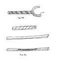
- FIG. 5illustrates a method of forming the flexible central portion of the invention by wrapping material into a spiral pattern
- FIG. 6illustrates a method of forming a flexible central portion according to one aspect of the invention
- FIG. 7illustrates a method of forming a flexible central portion according to one aspect of the invention using a sheet of material rolled to form a cylinder
- FIG. 8illustrates a method of forming a curved flexible central portion according to an embodiment of the invention
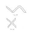
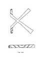
- FIG. 9illustrates a method of forming a flexible central portion according to one aspect of the invention using a material die-cut into a V-shape
- FIG. 10illustrates a method of forming a flexible central portion according to one aspect of the invention using a material die-cut into a hexagonal shape
- FIG. 11is a side view of a flexible central portion having notches die-cut into the material for flexibility
- FIGS. 12 and 12Aare side views of a flexible central portion according to an embodiment of the invention using a combination of solid rods and springs;
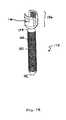
- FIG. 13is a side view of a flexible central portion incorporating a spiral pattern with a solid rod inserted therein;
- FIGS. 13A-Bare side views of flexible central portions according to the invention incorporating a flexible segment between two solid portions;
- FIG. 14is a side view of a braided flexible central portion according to an embodiment of the invention.
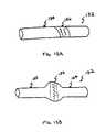
- FIGS. 15 and 15Aare side and perspective views of a flexible central portion incorporating a ball and socket joint for flexibility
- FIG. 16is a top view of a flexible central portion according to the invention incorporating a hinge for flexibility
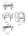
- FIGS. 17-20are frontal views of bone fasteners according to various embodiments of the invention.
- FIGS. 21-23are side views of the assembled system of the invention according to various embodiments discussed herein;
- FIG. 23Ais a side view of an assembled system of the invention using tension bands in addition to the flexible central portion;
- FIG. 24is a frontal view of a motion segment unit with bone fasteners driven therein.
- FIG. 25illustrates a side view of the system of invention as implanted within a motion segment unit.
- the present inventionis directed to flexible stabilization systems for use with the anterior, antero-lateral, lateral, and/or posterior portions of at least one motion segment unit of the spine.
- the systems of the inventionare designed to be conformable to the spinal anatomy, so as to be less intrusive to surrounding tissue and vasculature than existing solid stabilization systems.
- the system of the inventionis contemplated to be used on the cervical, thoracic, lumbar, and sacral segments of the spine.
- the size and mass increase of the vertebrae in the spine from the cervical to the lumbar portionsis directly related to an increased capacity for supporting larger loads.
- This increase in load bearing capacityis paralleled by a decrease in flexibility and an increase in susceptibility to strain.
- rigid immobilization systemsare used in the lumbar segment, the flexibility is decreased even further beyond the natural motion restriction of that segment. Replacing the conventional rigid immobilization systems with the present invention restores a more natural movement and provides added support to the strain-susceptible area.
- One embodiment of the spine stabilization system of the present inventionincludes at least two bone fasteners and at least one flexible element.
- the flexible elementadvantageously provides desirable properties for bending or twisting that allows the system to accommodate the natural spine movement.
- a flexible elementpreferably approximates or resembles a relatively circular tube or rod.
- a flexible elementmay have other shapes as well.
- the flexible elementmay have a cross-section that approximates or resembles a geometric shape, such as a triangle, square, rectangle, trapezoid, or the like.
- a central portion of at least one component of the flexible elementis hollow.
- art of the flexible elementmay resemble a hollow tube.
- the tubemay be formed by extruding a material, such as metal or polymeric materials, through a die. One or more slits may then be cut into the extruded material.
- a tubemay have a helical spiral slit cut along at least a portion of the tube.
- the tubemay have a plurality of diagonal slits cut into its surface. The slits may be machined into the tube, such as by turning the tube on a lathe, by milling the slits, or by other suitable methods.
- the tubemay also be formed from winding one or more flat strips of material.
- a thin strip of metalmay be wound in a generally spiral or helical shape in order to form a tube.
- the distance between a first edge of the strip and a second edgeforms a helical slit along the flexible element.
- the helical slitmay be continuous along the entire length of the flexible element or may be formed on only a portion of the flexible element, such as at the center or on one side.
- the present inventionmay also be used as a cross-brace or transconnector in communication with two rods along a portion of the length of the spine. It is well known that the strength and stability of a dual rod assembly can be increased by coupling the two rods with a transconnector that extends across the spine in a direction that is generally perpendicular to the longitudinal axes of the rods.
- the present inventionincludes a first fastener connecting the transconnector to a first rod and a second fastener connecting the transconnector to a second rod.
- the transconnectormay be connected to one or more bone fasteners associated with a rod. Examples of transconnector designs that may be improved by the present invention are described in U.S. Pat. No.
- the ability to selectively make the flexible element substantially rigidmay also be desirable in other applications of the invention in addition to transconnectors.
- the flexible elementinitially allows the surgeon to bend or twist the tranconnector as needed to connect or associate the transconnector to the first and second rods.
- One advantage of this feature of the inventionis that the flexible portion allows the surgeon to reposition or change the shape of the transconnector in order to avoid interfering with bony anatomy and then make the transconnector rigid in order to securely prevent movement of the first rod relative to the second rod.
- the flexible elementcan be configured in many different ways.
- the flexible elementmay be a relatively straight rod, tube, or plurality of rods and/or tubes, such as shown in FIG. 1 .
- the flexible elementmay have a curved shape that corresponds approximately to the natural curvature of the portion of the spine that it supports.
- the flexible elementmay be made of one or more tubes that is configured to allow the element to flex, bend, or twist.
- a tubemay be formed with slits or other openings that increase the flexibility of the tube. The slits may form a helical or spiral pattern on the tube, may form a pattern along a portion of the tube.
- the slitsalso may be on only a portion of the circumference of the tube to provide greater flexibility for a limited range of motion. If more than one tube is used, the wall thickness of each tube may be varied in order to achieve a desired response to bending or torsional forces.
- the flexible element of the system of the inventionprovides stability, strength, flexibility, and resistance without the traditional rigidity of prior systems. While the flexible element may be designed in a variety of ways according to the invention, the types of design may differ depending on the final implementation of the system, i.e., lateral, posterior, etc.
- the flexible elementmay include a straight or curved rod having a double helical pattern.
- FIGS. 1 and 2show non-limiting examples of the flexible element of the invention.
- the flexible elementincludes a first rod 10 having a first spiral pattern and a first diameter (d 1 ) and a second rod 14 having a second spiral pattern and a second diameter (d 2 ).
- Reference numerals 12 and 16refer to the edge of the flexible portion that forms the generally spiral-shaped pattern.
- the edge of the material forming one side of the spiral patternabuts or contacts the edge of the material on the opposing edge of the spiral.
- the flexible elementalso may be configured and adapted such that the contact between these two edges exhibits preload forces even when the flexible portion is not undergoing externally applied torsional, axial, or bending loads. In other words, the contact between the opposing edges causes each edge to apply loading to opposing edge.
- This preloaded configurationmay be beneficial for designing a preferential response to different types of external forces or loading.
- a preloaded flexible elementmay provide a greater resistance to torsional loads that would tend to further tighten the flexible element due to added frictional forces resisting sliding movement of the edges against each other.
- a preloaded flexible elementmay provide a system that has at least about 1.2 times greater resistance to torsional loads in one direction than in an opposite direction.
- a preloaded flexible elementmay provide at least about 1.4 times greater torsional resistance in one direction than another. Portions of one or both of the first and second rods may utilize a preloaded configuration to create a preferential response to certain loads.
- At least a portion of the material forming the edge of one side of the spiral patternmay not contact the material forming the edge of the opposing side of the spiral.
- the gap or space between the opposing edges of the spiral patternfurther increases the ability to custom tailor a system response to different types or locations of forces or loads applied to the system.
- the placement of gaps in the spiralmay permit the stabilization system to deflect or bend in a manner similar to normal motion of the segment unit.
- the width of the space between the opposing edges of the spiralmay be non-uniform in order to permit bending in one direction while resisting bending in another.
- the circumference of the rodmay have spaces or gaps permitting lateral or forward bending but limiting hyperextension of the segment in a rearward direction. More preferably, the spaces or gaps between the edges of the material defining the spiral pattern are on about 40 to about 60 percent of the circumference of the rod.
- the second rodmay be secured in place with respect to the first rod in any suitable manner.
- the second rodis substantially prevented from moving in an axial direction out of its desired position relative to the first rod.
- This preferred configurationcan be accomplished in several ways.
- the second rodmay fit snugly within the first rod in a manner that the interference fit or press fit prevents sliding or movement of the second rod in an axial direction relative to the first rod.
- the outer diameter of the second rod (d 2 ), when not subjected to external loading and prior to assembly,is slightly larger than the inner diameter of the first rod.
- the second rodhas an outer diameter that is about 102% to about 105% larger than the inner diameter of the first rod.
- the outer diameter of the second rodmay be from about 0.001 to about 0.010 inch greater than the inner diameter of the first rod.
- the first rodmay be expanded or the second rod may be contracted so that the second rod can be placed within the first rod.
- both diameters of the first and second rodsmay be altered during assembly. The diameters may be altered in a number of ways.
- torsional forcesmay be applied to the second rod to cause its outer diameter to decrease.
- the second rodmay be stretched or extended along its axis in order to reduce its outer diameter during assembly.
- torsional forcesmay be applied to the first rod in a direction that causes the spiral patters to partially unwind or open while the second rod is being positioned inside it
- the inner diameter of the first rodmay be expanded by elevating its temperature during assembly.
- the temperature of the first rodmay be elevated during assembly.
- the outer diameter of the second rodmay be reduced by lowering its temperature.
- the second rodis fitted inside the first rod simply by applying axial loads to the second rod in order to force it inside the first rod.
- the first and second rodsare secured together by applying a weld, adhesive, epoxy, or the like to a portion of the rods.
- first and second rodsare assembled using a press fit or interference fit.
- the rodsmay be secured together by a pin placed through at least a portion of both first and second rods.
- first and second rodsmay be configured and adapted such that the first and second rods have threading on their interior and exterior surfaces. The threaded portion of the outer surface of the second rod may then be threaded onto the interior threading of the first rod.
- the first and second rodsmay be secured together by applying a clamp to at least a portion of the first rod that surrounds the second rod.
- the second rodmay have an outside diameter that is less than the inside diameter of the first rod. This may not only facilitate easy assembly of the rods, but also may provide greater flexibility in response during bending or deflection.
- d 2is about 98 percent or less of d 1 .
- d 2is about 95 percent or less of d 1 .
- d 2is about 90 percent or less of d 1 .
- the difference in diametersbe such that the stability of the central portion is sufficiently maintained.
- the flexible elementincludes a first rod 18 curved in an arc-type shape and a second rod 22 also curved in a similar arc-type shape, wherein the second rod 22 is inserted into the first rod 18 .
- at least a portion of the rodshave edges that define a generally spiral shaped pattern.
- the opposing edges of the rod defining the patternmay contact each other with or without preload forces.
- the edges defining the patternmay be spaced apart from each other.
- the first and second spiral patternspreferably travel in opposite directions along the first and second rods.
- One benefit of this configurationis that is allows greater flexibility in balancing a response to torsional forces applied to the assembly of rods. If the patterns on both rods travel in the same direction, it would be difficult to achieve a balanced, or neutral, response to torsional forces applied in different directions because resistance to torsional forces causing the spiral to unwind would likely differ from resistance to torsional forces causing the spiral to be wound more tightly.
- One design parameterincludes the wall thicknesses of the first and second rods. For example, if a balanced or neutral response to torsional loading is desired, regardless of which direction the torque loading is applied, the wall thickness of the first rod may be slightly greater than the wall thickness of the second rod. Varying the wall thickness of the first and second rods also may allow the assembled rods to respond differently to torsional loads in different directions.
- both the first and second rods 10 , 14are formed having the same material thickness.
- the first and second rods 10 , 14have different material thicknesses.
- the first rod 10may be thicker than the second rod 14 for more outer stability.
- the second rod 14may be thicker than the first rod 10 to allow the flexible central portion to have more inner stability.
- the thickness of the first rod (t 1 )may differ from the thickness of the second rod (t 2 ) by about 1 percent or greater.
- t 1 and t 2differ from each other by about 5 percent or more.
- t 1 and t 2differ from each other by about 10 percent or more.
- the spiral patternmay be designed to have portions of solid area along the rod.
- the end portions of the flexible central portionmay be solid whereas the middle portion has the double helical pattern shown in FIGS. 1 and 2 .
- FIG. 3illustrates one such embodiment.
- the flexible central portion 30having an overall length L, has end portions 32 and 34 having lengths L 1 and L 2 and a middle portion 36 having a length L 3 .
- the end portions 32 and 34may be left as solid material to avoid depressing or detenting the material when the bone fasteners are attached.
- the appropriate length of the end portions 32 and 34may be designed to accommodate particular bone fasteners.
- end portions 32 , 34may have lengths (L 1 , L 2 ) of about 30 percent or less of the flexible central portion 30 .
- L 1 and L 2may be about 15 percent or less of the flexible central portion 30 .
- L 1 and L 2are each about 5 percent or less of the total length (L) of flexible central portion 30 .
- end portions 32 and 34may be defined in absolute terms.
- the end portionsmay be about 1.5 cm or less in length.
- the lengths of end portions 32 and 34may be about 1.0 cm or less, or even may be only about 0.5 cm or less.
- the lengths of L 1 and L 2need not be the same.
- one end portion 32may have a length of about 30 percent or less of the flexible central portion, which the other end may be best described as being only about 0.5 cm or less in length. Thus, it is not required that both end portions meet any one range.
- the middle portion 36 of the flexible element 30becomes the “flexible” segment.
- the middle portion 36may make up about 60 percent or greater of the flexible central portion, preferably about 80 percent or greater.
- the length of the middle portion (L 3 )is about 90 percent or greater of the total length of the flexible central portion.
- the ratio of L 3 to L 1 +L 2is preferably about 3:2, more preferably about 4:1.
- the ratio of L 3 to L 1 +L 2is about 9:1.
- the entire length of the rodsare flexible. In this embodiment, the lengths of L 1 and L 2 are zero.
- the solid endsmay be flattened and punched with eyelets. As shown in FIGS. 3A and 3B , the ends 32 and 34 are flattened and eyelets 33 and 35 are punched so as to allow attachment to the bone fasteners, e.g., screws may be inserted through the eyelets 33 and 35 .
- the middle portion 36remains cylindrical and flexible.
- spiral patterns on the rodsthere are numerous design parameters for the spiral patterns on the rods, such as the amount of preloading, contact, or spacing between the edges that define the spiral.
- the size, location, and number of spaces in the spiralenables one to fine tune the flexibility of the flexible central portion.
- an increase in the size of the empty spaces and/or number of empty spaces in the spiral patternwill have a direct effect on the flexibility and stability of the central portion. For example, a spiral pattern having fewer and/or smaller spaces or gaps will be more rigid in comparison to a spiral pattern having larger and/or larger spaces.
- the spaces or gaps ( 12 , 16 , 20 , 24 , 38 ) between each solid segmentis about 0.01 percent or greater of the total length (L) of the flexible central portion. In another embodiment, each empty space is about 0.1 percent or greater of the total length (L) of the flexible central portion. In still another embodiment, each empty space is about 1 percent or greater of the total length (L) of the flexible element.
- the ratio of each empty space 42 ( FIG. 4 ) to the two solid portions flanking the empty space ( 44 )is preferably about 1:4 to about 1:128. In another embodiment, the ratio of an empty space 42 to the two solid portions ( 44 ) on either side of the empty space 42 is about 1:8 to about 1:128. In still another embodiment, the empty space to solid portions ratio is about 1:32 to about 1:128.
- the spiral pattern in the flexible element 40has a number of empty spaces, openings, or slits 42 ( e ) and a number of solid portions 44 ( s ) flanking the empty spaces (FIG. 4 ).
- the flexible element 40may have a number of solid portions, wherein all of the solid portions together make up about x percent or greater of the flexible element. The remaining 100 ⁇ x percent or less of the total length (L) of the flexible element 40 is accounted for in the empty spaces 42 between the solid portions 44 .
- the length of each solid portion (L s ) with respect to the overall length (L) of the flexible central portion 40would be equal to 0.80*L/s.
- the width of each slitwas the same as the other slits (all equal to L e )
- the length of a slit opening (L e ) with respect to the overall length (L) of the flexible element 40would be equal to [(1.0 ⁇ x)*L]/e. Therefore, the ratio of the width of a slit to the widths of its two adjacent solid portions would be equal to ⁇ [(1.0 ⁇ x)*L]/e ⁇ /(0.80*L/s).
- the inventionalso includes spiral patterns with differing widths of the empty spaces 12 , 16 , 20 , 24 , and 38 of the slit openings. These difference may appear random in nature, localized, or patterned.
- FIG. 4demonstrates one variation of this concept.
- the slit openings 42have a first length (L e ), while the slit openings 43 have a greater length, denoted by L e+n if each solid portion 44 may be the same as the next solid portion in length (all equal to L s ).
- all of the solid portions 44are equal with respect to each other, but the slit openings 42 and 43 differ with respect to each other so that the variance is one where every other empty space 43 is twice the length of the nearest empty space 42 .
- the slit openings 43 towards the ends of the flexible element 40are larger than the slit openings 42 near the middle of the flexible element 40 .
- the slit openings near the middle of the flexible element 40may be larger than the slit openings near the ends (not shown).
- both the solid portions 44 and the slit openings 42are varied in size.
- the solid portions 45 near the ends of the flexible element 40may be smaller in comparison with the solid portions 44 near the middle of the flexible element and, likewise, the slit openings 42 near the ends of the flexible element may be smaller in comparison with the slit openings 43 near the middle of the flexible element.
- the solid portions near the middle of the flexible elementare larger than the solid portions at the ends of the flexible element and, similarly, the slit openings near the middle of the flexible element are larger than the slit openings at the ends of the flexible element.
- Another variation on this conceptwould involve a flexible element wherein the solid portions at the ends would be larger than the solid portions in the middle of the flexible element, and wherein the slit openings at the middle of the flexible element would be larger than the slit openings at the ends.
- the solid portions at the endswould be smaller than the solid portions in the middle of the flexible element, and wherein the slit openings at the middle of the flexible element would be smaller than the slit openings at the ends. While no generic equations are provided herein to describe such designs, those of ordinary skill in the art would be aware of how to determine the size of the slit openings 42 and solid portions 44 to accomplish the desired flexibility and stability.
- FIG. 5Aillustrates one suitable method for constructing the flexible element of the invention.
- a strip of material 52may be wound about a forming rod 50 to create a first flexible element 53 having a desired spiral pattern.
- the flexible elementmay be formed by winding two strips of material around a forming rod such that one side of the helical pattern is from a first strip while the opposing side is from the second strip.
- the helical patterncould also be formed by an even greater number of strips of material.
- the first flexible element 53has slit openings 54 and solid portions 56 as described above, which may vary in size and number depending on the tightness of the spiral desired.
- This first flexible element 53may be used alone as the sole flexible element in the system of the invention.
- a second flexible elementmay be formed using a similar method, wherein the diameter of the second flexible element is less than the diameter of the first flexible element 53 so that the second flexible element fits inside the first.
- Another way of forming the flexible elementwould be to form the first flexible element 53 using a forming rod 50 , and then forming a second flexible element directly on top of the first flexible element 53 (while still on the rod) using an opposite winding pattern to create the double helical pattern. The rod 50 may then be removed and the flexible element may be cut into discrete sections if necessary.
- the strips used to form a tubemay vary in thickness along their length. In this manner, the tube would exhibit varying flexibility and torsion resistance along its length. For instance, if it is desired that the center of the flexible element have the greatest flexibility or the least torsion resistance, the thickness of the strip used to form this part of the flexible element may be reduced.
- the stripmay also have a slot or opening machined or cut into it along at least a portion of its length to provide even greater flexibility. In embodiment, at least one strip has a slot or opening formed in about 20 to about 80 percent of the length of the strip.
- the slot formed on the stripis from about 30 to about 60 percent of the length of the strip, and in yet another embodiment, the slot is from about 40 to about 50 percent of the length of the strip. Preferably, the slot is located approximately at the middle of the strip.
- More than one slotmay be formed in the strip. For instance, it may be beneficial to provide a slot near each end of the strip. Additionally, the width of the slot or slots may be varied along the length of the strip. For example, a single slot positioned near the middle of the strip may be 1.3 times wider at the middle of the slot than at the ends. In another embodiment, the middle of the slot is about 1.5 times wider than the ends.
- Another method of forming the flexible element of the inventionincludes obtaining a piece of material having at least a known width (w) and a known thickness (t) (FIG. 6 ), and bending the material 60 so that the ends 61 and 63 meet to form a generally cylindrical tube.
- the ends 61 and 63may be fused, soldered, or otherwise joined (depending on the material 60 ) to form a rod.
- the flexible elementmay be formed from a sheet of material 68 that is rolled, crimped, and cut to form a rod or tube.
- the spiral patternmay then be formed in the preformed rod or tube by turning it on a lathe, mill cutting, laser cutting, water jet cutting, wire EDM cutting, or combinations thereof.
- the length (L) of the material 60 , 68is known before the material is formed into the rod to eliminate the additional step of cutting the tube or rod after forming.
- mass productionmay be accomplished by forming a long tube, cutting the spiral pattern in the tube, and then severing the tube at predetermined intervals to form the flexible element of 62 , 70 .
- a second tube having a smaller diametermay be formed in the same manner and inserted into the first tube having a larger diameter to form the flexible element 62 , 70 .
- the material 68may be die cut or stamped having a curvilinear pattern in the footprint (FIG. 8 ).
- the curved flexible element 70results.
- the width of the stripcan be varied such that the flexible portion of the strip corresponding to the outermost side (i.e. the part of the flexible portion farthest away from the radius of curvature) of the curved portion has a width ⁇ and the innermost side of the curved portion has a width ⁇ .
- the length x of FIG. 8corresponds to the circumference of the rod. The ratio of ⁇ to ⁇ for any length x governs the radius of curvature for that part of the flexible portion.
- the flexible elementis formed from a material 72 that is pre-cut into a V-shape (FIG. 9 ).
- the material 72is wound to form a spiral pattern having slit openings 76 and solid portions 78 , wherein the point of the V ( 71 ) translates into a solid segment 79 at the middle of the flexible element 74 .
- FIG. 10 AAnother variation of this concept is shown in FIG. 10 A.
- Material 80is pre-cut having an irregular hexagonal-shape, wherein the edges of the shape include tabs 81 , 83 with eyelets 82 , 84 punched therein. Once wound, a set screw inserted through the eyelets 81 , 83 (now adjacent each other) may tighten or loosen the spiral pattern in the flexible element 90 .
- FIGS. 10B-Dare illustrative of some of the additional pre-cut shapes that may be used to achieve a similar final construction.
- the flexible elementis formed from a multiple V-shaped sheet.
- FIG. 10Cshows an X-shaped sheet that can be rolled to form the flexible portion
- FIG. 10Dshows that the arms of an X-shaped sheet may be tapered to provide varying thickness along the length of the flexible portion.
- FIG. 10Dshows that the gaps or slit openings formed by the helical pattern may be larger near the center of the flexible element and become progressively smaller toward one or more ends.
- the sheetmay be treated or coated on one or both sides to reduce friction or galling.
- the application of the coating or treatmentpreferably is performed prior to rolling the material.
- an additional layer of materialmay be applied to the sheet prior to rolling, such as a high molecular weight polyetheylene.
- the flexible elementmay be formed from a pre-cut material 92 having notches 94 resembling a keyhole, such as shown in FIG. 11 A.
- the tips 96 of the notches 94are oval in shape. When a load is applied to the material 92 , the notches 94 close and the tips 96 become more circular in nature as shown in curved flexible element 98 .
- the flexible elementalso may be formed from a sheet of material that is pre-cut with slits prior to forming the tube. As shown, a first plurality of diagonal slits may be formed on one side of a sheet of material and a second plurality of diagonal slits may be formed on another side of the sheet.
- the first and second sets of slitsare formed on a portion of the sheet that corresponds approximately to the circumference x of the tube.
- the slitsmay be straight, as shown in FIG. 11B , may have a repeating wave form as shown in FIG. 11C , or may have any other pattern of slits desired.
- the sheetmay then be rolled to form the tube. This process may be used to form a single wall tube or to form a tube having two or more walls as illustrated.
- the flexible element according to the inventionmay be formed with an encased spring concept.
- solid rods 102pass through a flange 104 into a tube 106 .
- the solid rodsare attached to a spring 110 via attachment means 108 .
- the tube 106preferably has a diameter sufficient to allow movement of the rods 102 and attachment means 108 in response to the movement of the spring 108 .
- the spring 110is longer than shown in FIG. 12 and attachment means 108 are much closer to flanges 104 than in FIG. 12 , thus providing more potential flexibility to the flexible element 100 .
- the spring constantmay be varied to alter the flexibility of the flexible element 100 regardless of the length of the spring.
- the flexible elementmay be formed with a solid rod within a tube having a spiral pattern.
- the outside rod 121may be formed with much larger slit openings 123 between the solid portions 122 because a solid rod 124 is inserted into the outside tube 121 for greater stability.
- the solid rod 124preferably has a diameter such that the outside tube 121 is allowed sufficient flexibility to conform to the natural movements of the motion segment unit.
- the solid rodis formed to have different diameters along the length of the solid rod.
- the solid rodmay have segments 124 , 128 having smaller diameters on the outer edges 124 , 128 of the rod and a segment 126 having a larger diameter therebetween.
- the solid rodhas a flexible segment 130 somewhere along the length of the rod to allow for even greater system flexibility.
- This flexible segment 130may be the result of an accordion type construction using a flexible material, a spiral pattern cut into the solid material (similar to the outside rod), a spring-type construction, a hinge, a ball and socket joint, and the like.
- a flexible segmentmay be placed in a discrete portion of a solid rod as illustrated in FIGS. 13A and 13B .
- the solid rod 134has a segment of flexibility 136 somewhere within to mimic the range of motion that the damaged or removed facet exhibited.
- the segment of flexibility 136may be formed similarly to FIGS. 1 and 2 above with a spiral pattern, or it may be a separate portion to which two solid rods attach at either end.
- the flexible elementmay also be formed using a braided wire.
- FIG. 14illustrates three strands of material 142 , 143 , and 144 braided together to form a flexible central portion 140 .
- the strands 142 , 143 , 144may be formed from identical materials or may differ from each other.
- strand 142may be wire, whereas pieces 143 and 144 may be rubber-based.
- a solid rod(not shown) can be inserted into the braided flexible central portion.
- the solid rodis present while the material 142 , 143 , and 144 are braided. While FIG. 14 shows only three strands of material, this aspect of the invention encompasses multiple pieces braided with each other, as well as less than three strands braided together.
- the flexible central portionmay be formed using a joint concept.
- FIGS. 15 and 15Ashow a flexible central portion constructed having a ball and socket joint to enable flexibility.
- the flexible central portion 150includes a first solid rod 152 having a ball 154 at the end and a second solid rod 166 having a socket 158 formed to fit the ball 154 .
- the ball and socket jointallows rotational movement of the flexible central portion 150 so that the overall system may respond to spinal movements in a more natural fashion.
- FIG. 16illustrates a flexible central portion 160 having a hinge for flexibility.
- the flexible central portion 160includes a first wing 162 having a collar 164 and a second wing 166 having a pin 168 .
- the pin 168 and collar 164allow for lateral movement, but not rotational movement.
- the flexible elementmay be made from a variety of materials.
- flexible elementmay be made of any metal appropriate for surgical implantation, such as stainless steel, titanium, titanium alloy, chrome alloys.
- the flexible element of the systemmay be fashioned out of shape memory materials or alloys, such as nickel titanium.
- the flexible elementmay be formed from non-metallic materials including, but not limited to, carbon fiber, resin materials, plastics, and ceramics.
- the rod portionis formed from a bioresorbable material.
- non-bioresorbable materialsincluding silicone, polyurethane, polyester, polyether, polyalkene, polyamide, poly(vinyl) fluoride, polytetrafluoroethylene (PTFE), silk, glass, carbon fiber, and mixtures thereof may be used to form any part of the flexible element.
- non-bioresorbable materialsincluding silicone, polyurethane, polyester, polyether, polyalkene, polyamide, poly(vinyl) fluoride, polytetrafluoroethylene (PTFE), silk, glass, carbon fiber, and mixtures thereof may be used to form any part of the flexible element.
- composite materialssuch as a matrix of fibers, may be used to form at least a part of the flexible element.
- the selection of materialshas a host of effects on the performance of the formed flexible element.
- the flexural rigidity, modulus of elasticity (i.e., degree to which a material deforms as a result of a given stress), and thickness of the selected materialwill effect the amount of deflection (i.e., the relative stiffness of the flexible central portion), flexural modulus, torsional rigidity of the flexible element.
- a flexible element made from metalwill have a higher flexural rigidity than the same flexible element made from a rubber-based material.
- the material selectionis only one way to control the properties of the flexible element.
- the propertiesmay likewise be controlled, at least in part, by adjusting the degree of curvature of the flexible element.
- the amount of deflectionis directly related to the amount of strain energy, which is, in turn, directly related to the degree of curvature of the flexible element and inversely related to the modulus and thickness of the material. Therefore, the characteristics of the flexible element are dependent on the modulus of elasticity, material thickness, radius of curvature, and arc of curvature. For example, by decreasing the radius of curvature and increasing the arc measure and holding all other parameters constant, more flexibility (less stiffness) may be imparted to the flexible central portion and the amount of deflection may also be increased. In addition, altering the modulus of elasticity and holding material thickness, radius of curvature, and arc of curvature constant, the relative stiffness any part of the flexible element may be adjusted.
- the bone fasteners included in the system of the inventioninclude any type of fastener that may be attached to the flexible central portion of the invention, while remaining securely fastened onto the intended bone.
- the bone fastenersmay include polyaxial screws, helical blades, expandable screws, such as Mollie bolt type fasteners, which are inserted or screwed into the bone and expand by way of some type of expansion mechanism, conventional screws, staples, sublaminar hooks, and the like.
- the bone fastenersare coated with any number of suitable osteoinductive or osteoconductive materials to enhance fixation in the bone.
- the bone fastenersare fenestrated to enhance bony ingrowth or to further anchor the fastener to the bone.
- the bone fastenersare polyaxial screws, such as the one shown in FIG. 17 .
- the polyaxial screwspreferably include a linear middle segment 180 with a tapered tip and a plurality of protrusions 184 , which defines the insertion segment of the fastener 180 , and a receiving segment 186 .
- the receiving segmentmay be a separate, attachable unit to be added after the fastener is inserted into the bone.
- the insertion segmentpreferably has a tapered tip 182 for easier insertion into the bone.
- the tapered tipdefines an angle of 60° or less, preferably about 45° or less.
- the plurality of protrusions 184extend laterally from the linear middle segment 180 .
- the at least one protrusionpreferably has a leading edge designed to follow the general design of the tapered tip 182 of the insertion segment 180 .
- the leading edgedefines an angle of 60° or less, preferably about 45° or less.
- the height of each protrusiongreatly depends on the number of protrusions present on the linear middle segment 180 .
- One of ordinary skill in the artwould be aware of how to select the number, angle, and height of the protrusions so as to provide optimal bone fastening.
- the receiving segment 186 of the bone fastener 178may be fashioned in a number of ways, all of which preferably involve providing the receiving segment the ability to accept the flexible central portion of the system.
- the receiving segmentmay be designed to be top loading, side loading, eye-hole loading, and the like.
- FIG. 17illustrates a receiving segment having a collar 188 and a side-loading head 190 . Once inserted into the bone, the collar may be placed over the top 185 of the insertion segment 180 . A tool may then be used to push the locking bar 192 of the head 190 down over the collar.
- FIG. 18shows a top-loading head 190 that is already locked down into place over insertion segment top 185 .
- the bone fastenermay be designed to have rotational capabilities. In one embodiment, the bone fastener has at least about 10 degrees of rotational freedom. In one embodiment, the bone fastener has at least about 20 degrees of rotational freedom. In still another embodiment, as shown in FIG. 19 , the bone fastener has about 30 degrees or freedom or greater. In yet another embodiment, the bone fastener has about 45 degrees of freedom or greater.
- the freedom of the receiving segmentmay be accomplished in a variety of ways.
- the insertion segment 180 and receiving 186 segmentmay function like a ball and socket joint (as shown in FIG. 20 ), where the rotation mechanism of the joint allows articulation within some spherical range of motion.
- the top 185 of the insertion segment 180functions as the “ball” and the receiving segment 186 functions as the “socket”.
- a flexible segmentis incorporated into the bone fastener (as depicted by the dashed segment near the top 185 of insertion segment 18 in FIG. 17 ).
- the bone fastenersmay be made from a host of materials.
- the fastenersmay be formed from natural/biological materials, such as allograft, xenograft, and cortical bone.
- the fastenersmay also be formed from synthetic bioresorbable materials, such as polyanhydride, polyactide, polyglycolide, polyorthoester, polyphosphazene, calcium phosphate, hydroxyapatite, bioactive glass, tyrosine-derived polycabonate, and mixtures thereof.
- the fastenersare formed from non-bioresorbable materials including, but not limited to, stainless steel, titanium, titanium alloys, cobalt chrome alloys, shape-memory alloys, and carbon-reinforced polymer composites.
- the fastenersmay include growth factors for bone ingrowth and bony attachment, or for soft tissue ingrowth.
- growth factorsinclude insulin-like growth factor 1, basic fibroblast growth factor, transforming growth factor ⁇ -1, platelet-derived growth factor, bone-derived growth factors, arginine, bone morphogenetic protein, LIM mineralization protein, and combinations thereof.
- the flexible elementalso may be used in other component of a spinal fixation system.
- itmay be used as part of a transconnector.
- the flexible elementmay be disposed between two fasteners connected to rods positioned along the length of the spine.
- Any fastener that may be suitable for a conventional transconnectormay be used with the present invention.
- Some examples of fastenersare described in U.S. Pat. No. 6,565,565 to Yuan, U.S. Pat. No. 6,562,040 to Wagner, U.S. Pat. No. 6,551,318 to Stahurski, and U.S. Pat. No. 6,540,749 to Schafer, all of which are incorporated herein in their entireties.
- the flexible elementmay be connected to fasteners in a number of ways, i.e., so that the connection is constrained, unconstrained, articulated, or combinations thereof.
- the flexible elementmay be constrained or rigidly fixed within the receiving element of the insertion segment.
- the flexible element 200would be flexible only between the two bone fasteners 210 and 220 .
- the flexible elementmay be inserted into heads 212 and 222 , which can be side-loading or top-loading in this aspect of the invention. Following the placement of the flexible element within the heads 212 and 222 , clamping screws 224 and 226 are inserted into the heads and firmly screwed down securing all the connected elements in place. This design would allow flexibility between the two bone fasteners only.
- the flexible element 200is not fixed to the heads 212 and 222 of the bone fasteners 210 and 220 , but instead is able to slide longitudinally within the heads 212 and 222 . This may be accomplished using heads with eyeholes, as discussed above. In such an embodiment, it is preferable that the heads and/or flexible element have means for limiting the slidability so that the flexible element does not move completely though the eyehole. Pins or bars may be sufficient to accomplish this “stop” mechanism. Thus, in this embodiment, the flexible element would be able to flex between the bone fasteners and also shift longitudinally within the receiving elements.
- the system of the inventionmay include a solid rod 230 inserted into the side-loading, top-loading, or eyehole loading heads 242 and 252 of the bone fasteners 240 and 250 .
- a flexible fastener element 244 , 254 in each of the bone fasteners 240 and 250allows a specific range of motion defined by each bone fasteners degrees of freedom. As discussed above, this general concept may also be accomplished using bone fasteners having ball and socket joint fittings as shown in FIG. 20 .
- the bone fasteners 240 and 250have about 10 degrees or greater degrees of freedom. In another embodiment, the bone fastener has at least about 20 degrees of freedom. In still another embodiment, the bone fastener has about 30 degrees or freedom or greater. In yet another embodiment, the bone fastener has about 45 degrees of freedom or greater. While a solid rod is depicted in FIG. 22 , it is contemplated that bone fasteners having flexible fastener elements may also be used with any of the embodiments described herein. In fact, using bone fasteners with rotational capability in combination with a flexible element may impart both flexibility though axis rotation of the flexible element and the bone fastener, as well through bending capability.
- FIG. 23Another way to impart motion capability to the system of the invention is illustrated in FIG. 23 .
- the flexible element 260is encased within a solid tube 262 .
- the solid tube 262preferably has a diameter large enough to allow the flexible central portion 260 to bend laterally and longitudinally in response to the natural spinal movement.
- the bone fasteners 270 and 280also impart some motion to the system, although the motion is limited by the angle ⁇ between the solid tube 262 and the bone fasteners 270 and 280 .
- FIG. 23 AAnother variation on the construction of the system includes one with tension bands on both sides of the flexible central portion, as shown in FIG. 23 A.
- This systemincludes a flexible central portion 260 , bone fasteners 270 and 280 securing the bone fasteners 270 and 280 , and two tension bands 264 and 266 .
- the tension bandsmay be made with a variety of materials, such as wire cables, flexible plastics, rubber-based materials, among others having the properties needed to provide tension capability to the system.
- the flexible central portion 260acts a shock absorber in compression of the motion segment unit and restores the natural height of the unit and the tension bands 264 and 266 act to limit the amount of tension in the unit. When a tension force is applied, the tension bands 264 and 266 become taught through flexion or extension.
- One or more tension bandsalso may be disposed within a hollow flexible element such as a tube, a plurality of tubes, or in several of the other embodiments.
- the systemmay use the flexible element depicted in FIGS. 3A-B , wherein the flexible central portion is loaded onto the bone fasteners before the heads of the bone fasteners are connected.
- the eyelets in the ends of the flexible central portion shown in FIGS. 3A-Bmay be concave in order to receive another identical concave eyelet to reduce shearing.
- the heads of the bone fastenersmay be fixed or have rotational capability depending on the flexibility desired of the system.
- adjustable connectorsmay be used to correct any non-linear patterns of the bone fasteners once inserted into the bone.
- the bone fastenersmay not line up vertically.
- FIG. 24shows bone fasteners 290 , 292 , 294 , and 296 connected to the bone, wherein the bone fasteners 290 and 292 and bone fasteners 294 and 296 do not line up vertically with respect to each other.
- at least one adjustable connector 291 , 295may be used to compensate for this non-linear pattern.
- the adjustable connectormay be rigid or flexible in nature depending on the desired stiffness of the system.
- the stiffness of the system of the inventionmay also be adjusted during the operation and post-operation using a set screw. This would allow surgeons and doctors to make adjustments depending on a specific scenario.
- the systemonce assembled, may serve a variety of functions in the motion segment unit (FIG. 25 ).
- the systemmay reduce the load on the degenerative disc and/or facet joints in the motion segment unit.
- the height of the adjacent vertebraemay be restored to eliminate crushing or slipping of the disc therebetween.
- lordosismay be created/preserved using the system of the invention in at least one motion segment unit of the spine.
- the stiffness of the motion segment unitmay be restored with the implementation of the system of the invention.
- kitsincluding various flexible segment portions, rigid rods, and various bone fasteners, as well as the tools needed for surgery.
- the kits of the inventionare intended to broaden a surgeon's options once in surgery to provide a patient with the most optimal spine stabilization system. By containing the most common instrument needs and options for assembling the actual spine stabilization of the invention, the revisions are completed faster and with fewer sets from central supply. Overall, there is less of a labor burden on hospital staff and procedure time is reduced by having all required instruments in one convenient kit.
- An example kitmay include two of each flexible elements depicted in FIGS. 1-4 , 11 , and 12 - 16 , two rigid rods, six of each of the bone fasteners depicted in FIGS. 17-20 , cutters, an awl, forceps, screwdriver, probe, and at least one locking tool adaptable for use with the bone fasteners.
- Bone fastenersmay be manufactured in varying widths and lengths and the flexible element may also come in various lengths.
- bone fastener cutters and cutters for the flexible elementare included within the kit to cut the selected parts of the system to any desired size.
- the flexible elementis a braided wire
- simple wire cuttersmay be used to cut the flexible element to the desired size.
- manual screw cutters and gas-powered screw cuttersare contemplated for use with the present invention.
- the present inventionmay be used to form other component that may be included in a kit.
- the present inventionmay be used to form a transconnector between two rods.
- the present inventionis capable of becoming rigid once it is n a desired position.
- the surgeonis able to flex or more portions of the transconnector around bony anatomy. Once it is in a desired position, the flexible portion may then be made rigid so that the rod resists flexural and torsional forces.
- transconnector designsthat may be improved by the present invention are described in U.S. Pat. No. 5,743,911 to Cotrel, U.S. Pat. No. 5,651,789 to Cotrel, U.S. Pat.
Landscapes
- Health & Medical Sciences (AREA)
- Orthopedic Medicine & Surgery (AREA)
- Life Sciences & Earth Sciences (AREA)
- Surgery (AREA)
- Neurology (AREA)
- Molecular Biology (AREA)
- General Health & Medical Sciences (AREA)
- Biomedical Technology (AREA)
- Heart & Thoracic Surgery (AREA)
- Medical Informatics (AREA)
- Nuclear Medicine, Radiotherapy & Molecular Imaging (AREA)
- Animal Behavior & Ethology (AREA)
- Engineering & Computer Science (AREA)
- Public Health (AREA)
- Veterinary Medicine (AREA)
- Surgical Instruments (AREA)
- Prostheses (AREA)
- Pharmaceuticals Containing Other Organic And Inorganic Compounds (AREA)
- Plural Heterocyclic Compounds (AREA)
- Manipulator (AREA)
- Orthopedics, Nursing, And Contraception (AREA)
Abstract
Description
The present invention relates to soft stabilization systems for spinal motion segment units. In particular, the present invention is directed to a soft stabilization system including at least two bone fasteners and a flexible central portion conformable to the natural spinal movement.
The spine includes a series of joints routinely called motion segment units, which is the smallest component of the spine that exhibits kinematic behavior characteristic of the entire spine. The motion segment unit is capable of flexion, extension, lateral bending and translation. The components of each motion segment unit include two adjacent vertebrae and their apophyseal joints, the intervertebral disc, and the connecting ligamentous tissue. Each component of the motion segment unit contributes to the mechanical stability of the joint.
Components of a motion segment that move out of position or become damaged can lead to serious pain and may lead to further injury to other components of the spine. Depending upon the severity of the structural changes that occur, treatment may include fusion, discectomy, laminectomy.
Underlying causes of structural changes in the motion segment unit leading to instability include trauma, degeneration, aging, disease, surgery, and the like. Thus, rigid stabilization of the motion segment unit may be the most important element of a surgical procedure in certain cases (i.e., injuries, deformities, tumors, etc.), whereas it is a complementary element in others (i.e., fusion performed due to degeneration). The purpose of rigid stabilization is the immobilization of a motion segment unit.
As mentioned above, the current surgical techniques typically involve fusing of the unstable motion segment unit and possibly, the removal of ligaments, bone, disc, or combinations thereof included in the unstable motion segment unit prior to fusing. There are several disadvantages to fusion, however. For example, the fusing process results in a permanent or rigid internal fixation of all or part of the intervertebral joints and usually involves metallic rods, plates, and the like for stabilization. In all cases, the systems are intended to rigidly immobilize the motion segment unit to promote fusion within that motion segment unit.
In addition to a loss of mobility, fusion also causes the mobility of the motion segment to be transferred to other motion segments of the spine. The added stresses transferred to motion segments neighboring the fused segment can cause or accelerate degeneration of those segments. One other disadvantage to fusion is that it is an irreversible procedure. In addition, fusion of a motion segments has a clinical success of approximately 70 percent, and often does not alleviate pain experienced by the patient.
Thus, while such fusion systems have been used since the early 1960's, the inherent rigid design have often caused stress concentrations and have directly and indirectly contributed to the degeneration of the joints above and below the fusion site (as well as at the fusion site itself). In addition, rigid, linear bar-like elements eliminate the function of the motion segment unit. Finally, removal of portions of the motion segment unit reduces the amount of support available for the affected motion segment unit.
Fusion procedures can be improved by modifying the load sharing characteristics of the treated spine. Thus, it would be desirable to allow more of a physiologic loading between pedicular fixation and anterior column support. It would also be desirable to have a device that precludes or at least delays the need for fusion for all but the most advanced degeneration of a motion segment, particularly if such a device would allow close to normal motion and pain relief.
Thus, a need exists in the art for a soft spine stabilization system that replicates the physiologic response of a healthy motion segment.
The present invention is generally directed towards a flexible spinal stabilization system that can provide load sharing either as an enhancement to a fusion device or as a motion-preserving non-fusion device.
One embodiment of the invention relates to a novel flexible prosthesis for intervertebral or intersegmental stabilization designed to load share with a graft in the anterior column that allows for graft resporption while ensuring compressive loading on the graft for fusion procedures in the spine.
Another embodiment of the invention is directed towards a novel prosthesis for intervertebral or intersegmental stabilization designed to ensure proper alignment and motion between vertebrae of the spinal column that helps partially unload the discs and facet joints to give pain relief.
One embodiment of the invention relates to a flexible spine stabilization system having a first flexible element with a tubular structure that has at least one slit formed in it, and a second flexible element disposed within the first flexible element. The second flexible element also has a tubular structure with at least one slit formed in it. One or more fasteners may be connected to or in communication with one of the flexible elements.
The slit or slits formed on either or both of the tubular structures may form a generally helical pattern around a longitudinal axis of the tubular structure. In one embodiment having one flexible element disposed within another, a helical pattern on one tubular structure of one flexible element travels in the opposite direction as a helical pattern on another tubular structure of another flexible element. The flexible elements of the invention may be straight or curved in a neutral position to accommodate the lordosis in the spine.
Several embodiments of the invention relate to the degree to which the flexible elements permit rotation, flexion-extension, lateral bending, or axial compression. For instance, in one embodiment of the invention movement of a first end of a flexible element relative to a second end is limited to a range of from about 1° to about 30° in all planes. In another embodiment, the range of motion is limited to a range of from about 0° to about 3° in all planes.
One embodiment of the invention limits rotation of a first end of a flexible element relative to a second end to a range of from about 1° to about 30°, while in another embodiment the range is limited from about 1° to about 6°. In yet another embodiment, rotation is limited to a range of from about 0° to about 3°. In another embodiment, the flexible element prevents rotation of the first end relative to the second end.
In one embodiment limits flexion-extension of a first end of a flexible element relative to a second end to a range of from 0° to about 30°. Alternatively, the range of flexion-extension may be limited to a range from about 0° to about 3°, and in yet another embodiment the range may be from about 3° to about 30°.
Lateral bending of a first end of a flexible element relative to a second end likewise may be limited to a prescribed range. For instance, in one embodiment lateral bending is limited to a range about 0° to about 30°, while in another embodiment it is limited from about 0° to about 3°. In yet another embodiment, lateral bending of the flexible element is limited to a range from 3° to about 30°.
In one embodiment, the first flexible element limits axial compression of a first end of a flexible element relative to a second end to a range from about 0 mm to about 7 mm. In another embodiment, axial compression is limited to a range from about 0.5 mm to about 7 mm, while in another embodiment it is limited from about 0 mm to about 1 mm.
Locking mechanisms may be used in any of the embodiments of the invention. Thus, in one embodiment of the invention a locking mechanism may secure one or more flexible elements in a rigid configuration. One benefit of this feature, for example, is that the surgeon may have flexibility of the system when positioning the components to avoid bony anatomy, but then be able to make the system more rigid once the component is in its desired position or configuration. In one embodiment, the locking mechanism comprises a cable disposed within a flexible element. The cable can be tensioned to secure one or more flexible elements in a rigid configuration. In another embodiment, the locking mechanism comprises a cable disposed outside of said a flexible element, and as the cable is tensioned it secures one or more flexible elements in a rigid configuration.
In one embodiment of the invention, a solid rod is disposed within the tubular structure of a flexible element to increase the stiffness of the flexible element.
The flexible element of the invention may be used to as part of various components of a spine stabilization system. For instance, the flexible element may form all or part of one or more rods. In another embodiment, the flexible element may also form at least part of a transconnector. Depending on what component of the spine stabilization system uses the invention, fasteners may also be connected to the component. For instance, in one embodiment the flexible element is connected to bone fasteners, such as pedicle screws or the like.
The present invention is directed to flexible stabilization systems for use with the anterior, antero-lateral, lateral, and/or posterior portions of at least one motion segment unit of the spine. The systems of the invention are designed to be conformable to the spinal anatomy, so as to be less intrusive to surrounding tissue and vasculature than existing solid stabilization systems.
The system of the invention is contemplated to be used on the cervical, thoracic, lumbar, and sacral segments of the spine. For example, the size and mass increase of the vertebrae in the spine from the cervical to the lumbar portions is directly related to an increased capacity for supporting larger loads. This increase in load bearing capacity, however, is paralleled by a decrease in flexibility and an increase in susceptibility to strain. When rigid immobilization systems are used in the lumbar segment, the flexibility is decreased even further beyond the natural motion restriction of that segment. Replacing the conventional rigid immobilization systems with the present invention restores a more natural movement and provides added support to the strain-susceptible area.
One embodiment of the spine stabilization system of the present invention includes at least two bone fasteners and at least one flexible element. The flexible element advantageously provides desirable properties for bending or twisting that allows the system to accommodate the natural spine movement. As used herein, a flexible element preferably approximates or resembles a relatively circular tube or rod. A flexible element may have other shapes as well. For instance the flexible element may have a cross-section that approximates or resembles a geometric shape, such as a triangle, square, rectangle, trapezoid, or the like.
Preferably, a central portion of at least one component of the flexible element is hollow. As mentioned above, for instance, art of the flexible element may resemble a hollow tube. A skilled artisan would appreciate that there are several ways to form a hollow tube, regardless of whether it is circular or has any other cross-sectional shape. For example, the tube may be formed by extruding a material, such as metal or polymeric materials, through a die. One or more slits may then be cut into the extruded material. For instance, a tube may have a helical spiral slit cut along at least a portion of the tube. Alternatively, the tube may have a plurality of diagonal slits cut into its surface. The slits may be machined into the tube, such as by turning the tube on a lathe, by milling the slits, or by other suitable methods.
The tube may also be formed from winding one or more flat strips of material. For instance, a thin strip of metal may be wound in a generally spiral or helical shape in order to form a tube. The distance between a first edge of the strip and a second edge forms a helical slit along the flexible element. The helical slit may be continuous along the entire length of the flexible element or may be formed on only a portion of the flexible element, such as at the center or on one side.
The following examples describe embodiments using a flexible rod, tube, or other structure. It should be understood that in these examples the different types of flexible elements described herein may be replaced with a flexible element having different shapes or configurations, including the many variations described herein.
The present invention may also be used as a cross-brace or transconnector in communication with two rods along a portion of the length of the spine. It is well known that the strength and stability of a dual rod assembly can be increased by coupling the two rods with a transconnector that extends across the spine in a direction that is generally perpendicular to the longitudinal axes of the rods. When used as a transconnector, the present invention includes a first fastener connecting the transconnector to a first rod and a second fastener connecting the transconnector to a second rod. Alternatively, the transconnector may be connected to one or more bone fasteners associated with a rod. Examples of transconnector designs that may be improved by the present invention are described in U.S. Pat. No. 5,743,911 to Cotrel, U.S. Pat. No. 5,651,789 to Cotrel, U.S. Pat. No. 6,139,548 to Errico, U.S. Pat. No. 6,306,137 to Troxell, U.S. Pat. No. 5,947,966 to Drewry, U.S. Pat. No. 5,624,442 to Mellinger, and U.S. Pat. No. 6,524,310 to Lombardo, all of which are incorporated herein in their entirety. When a flexible element of the present invention is included in a transconnector design, it is preferred that the flexible element can be selectively made substantially rigid once the transconnector is in its desired position. The ability to selectively make the flexible element substantially rigid may also be desirable in other applications of the invention in addition to transconnectors. The flexible element initially allows the surgeon to bend or twist the tranconnector as needed to connect or associate the transconnector to the first and second rods. One advantage of this feature of the invention is that the flexible portion allows the surgeon to reposition or change the shape of the transconnector in order to avoid interfering with bony anatomy and then make the transconnector rigid in order to securely prevent movement of the first rod relative to the second rod.
As explained in greater detail below, the flexible element can be configured in many different ways. For instance, the flexible element may be a relatively straight rod, tube, or plurality of rods and/or tubes, such as shown in FIG.1. Alternatively, the flexible element may have a curved shape that corresponds approximately to the natural curvature of the portion of the spine that it supports. In each embodiment, the flexible element may be made of one or more tubes that is configured to allow the element to flex, bend, or twist. For instance, a tube may be formed with slits or other openings that increase the flexibility of the tube. The slits may form a helical or spiral pattern on the tube, may form a pattern along a portion of the tube. The slits also may be on only a portion of the circumference of the tube to provide greater flexibility for a limited range of motion. If more than one tube is used, the wall thickness of each tube may be varied in order to achieve a desired response to bending or torsional forces.
The Flexible Element
The flexible element of the system of the invention provides stability, strength, flexibility, and resistance without the traditional rigidity of prior systems. While the flexible element may be designed in a variety of ways according to the invention, the types of design may differ depending on the final implementation of the system, i.e., lateral, posterior, etc.
In a posterior application, for example, the flexible element may include a straight or curved rod having a double helical pattern.FIGS. 1 and 2 show non-limiting examples of the flexible element of the invention. InFIG. 1 , for example, the flexible element includes afirst rod 10 having a first spiral pattern and a first diameter (d1) and asecond rod 14 having a second spiral pattern and a second diameter (d2). Reference numerals12 and16 refer to the edge of the flexible portion that forms the generally spiral-shaped pattern.
In some embodiments, the edge of the material forming one side of the spiral pattern abuts or contacts the edge of the material on the opposing edge of the spiral. The flexible element also may be configured and adapted such that the contact between these two edges exhibits preload forces even when the flexible portion is not undergoing externally applied torsional, axial, or bending loads. In other words, the contact between the opposing edges causes each edge to apply loading to opposing edge.
This preloaded configuration may be beneficial for designing a preferential response to different types of external forces or loading. For instance, a preloaded flexible element may provide a greater resistance to torsional loads that would tend to further tighten the flexible element due to added frictional forces resisting sliding movement of the edges against each other. Thus, a preloaded flexible element may provide a system that has at least about 1.2 times greater resistance to torsional loads in one direction than in an opposite direction. In one embodiment, a preloaded flexible element may provide at least about 1.4 times greater torsional resistance in one direction than another. Portions of one or both of the first and second rods may utilize a preloaded configuration to create a preferential response to certain loads.
In other embodiments of the invention at least a portion of the material forming the edge of one side of the spiral pattern may not contact the material forming the edge of the opposing side of the spiral. The gap or space between the opposing edges of the spiral pattern further increases the ability to custom tailor a system response to different types or locations of forces or loads applied to the system. The placement of gaps in the spiral may permit the stabilization system to deflect or bend in a manner similar to normal motion of the segment unit. Moreover, the width of the space between the opposing edges of the spiral may be non-uniform in order to permit bending in one direction while resisting bending in another. For example, from about 30 to 85 percent of the circumference of the rod may have spaces or gaps permitting lateral or forward bending but limiting hyperextension of the segment in a rearward direction. More preferably, the spaces or gaps between the edges of the material defining the spiral pattern are on about 40 to about 60 percent of the circumference of the rod.
The second rod may be secured in place with respect to the first rod in any suitable manner. Preferably, the second rod is substantially prevented from moving in an axial direction out of its desired position relative to the first rod. This preferred configuration can be accomplished in several ways. For example, the second rod may fit snugly within the first rod in a manner that the interference fit or press fit prevents sliding or movement of the second rod in an axial direction relative to the first rod.
When the first and second rods are secured together by an interference fit, the outer diameter of the second rod (d2), when not subjected to external loading and prior to assembly, is slightly larger than the inner diameter of the first rod. Preferably, the second rod has an outer diameter that is about 102% to about 105% larger than the inner diameter of the first rod. Alternatively, the outer diameter of the second rod may be from about 0.001 to about 0.010 inch greater than the inner diameter of the first rod. During assembly, the first rod may be expanded or the second rod may be contracted so that the second rod can be placed within the first rod. Alternatively, both diameters of the first and second rods may be altered during assembly. The diameters may be altered in a number of ways. For instance, torsional forces may be applied to the second rod to cause its outer diameter to decrease. Additionally, the second rod may be stretched or extended along its axis in order to reduce its outer diameter during assembly. Likewise, torsional forces may be applied to the first rod in a direction that causes the spiral patters to partially unwind or open while the second rod is being positioned inside it
Alternatively, the inner diameter of the first rod may be expanded by elevating its temperature during assembly. For example, the temperature of the first rod may be elevated during assembly. Similarly, the outer diameter of the second rod may be reduced by lowering its temperature.
In yet another embodiment of the invention, the second rod is fitted inside the first rod simply by applying axial loads to the second rod in order to force it inside the first rod. In another embodiment, the first and second rods are secured together by applying a weld, adhesive, epoxy, or the like to a portion of the rods.
It is not required, however, that the first and second rods are assembled using a press fit or interference fit. For example, the rods may be secured together by a pin placed through at least a portion of both first and second rods. In yet another embodiment the first and second rods may be configured and adapted such that the first and second rods have threading on their interior and exterior surfaces. The threaded portion of the outer surface of the second rod may then be threaded onto the interior threading of the first rod. Additionally, the first and second rods may be secured together by applying a clamp to at least a portion of the first rod that surrounds the second rod.
When an interference fit is not utilized to secure the first and second rods together, the second rod may have an outside diameter that is less than the inside diameter of the first rod. This may not only facilitate easy assembly of the rods, but also may provide greater flexibility in response during bending or deflection. In one embodiment, d2is about 98 percent or less of d1. In another embodiment, d2is about 95 percent or less of d1. In still another embodiment, d2is about 90 percent or less of d1. One of ordinary skill in the art would appreciate that while a larger difference between the two diameters would generally result in greater flexibility of the flexible central portion, such differences may also lead to less stability of the central portion because of the potential of the second rod to slip within the first rod. Thus, it is preferred that the difference in diameters be such that the stability of the central portion is sufficiently maintained.
InFIG. 2 , the flexible element includes afirst rod 18 curved in an arc-type shape and asecond rod 22 also curved in a similar arc-type shape, wherein thesecond rod 22 is inserted into thefirst rod 18. As inFIG. 1 , at least a portion of the rods have edges that define a generally spiral shaped pattern. As described above, the opposing edges of the rod defining the pattern may contact each other with or without preload forces. Alternatively, the edges defining the pattern may be spaced apart from each other.
The first and second spiral patterns preferably travel in opposite directions along the first and second rods. One benefit of this configuration is that is allows greater flexibility in balancing a response to torsional forces applied to the assembly of rods. If the patterns on both rods travel in the same direction, it would be difficult to achieve a balanced, or neutral, response to torsional forces applied in different directions because resistance to torsional forces causing the spiral to unwind would likely differ from resistance to torsional forces causing the spiral to be wound more tightly.
As illustrated above, there are many parameters of the invention that may be adjusted to create a desired response under different types of loading. One design parameter includes the wall thicknesses of the first and second rods. For example, if a balanced or neutral response to torsional loading is desired, regardless of which direction the torque loading is applied, the wall thickness of the first rod may be slightly greater than the wall thickness of the second rod. Varying the wall thickness of the first and second rods also may allow the assembled rods to respond differently to torsional loads in different directions.
In one embodiment, both the first andsecond rods second rods first rod 10 may be thicker than thesecond rod 14 for more outer stability. In contrast, thesecond rod 14 may be thicker than thefirst rod 10 to allow the flexible central portion to have more inner stability. In this aspect of the invention, the thickness of the first rod (t1) may differ from the thickness of the second rod (t2) by about 1 percent or greater. In one embodiment, t1and t2differ from each other by about 5 percent or more. In another embodiment, t1and t2differ from each other by about 10 percent or more.
The spiral pattern may be designed to have portions of solid area along the rod. For example, because the flexible central portion is ultimately attached to bone fasteners, the end portions of the flexible central portion may be solid whereas the middle portion has the double helical pattern shown inFIGS. 1 and 2 .FIG. 3 illustrates one such embodiment. The flexiblecentral portion 30, having an overall length L, hasend portions middle portion 36 having a length L3. Theend portions end portions end portions central portion 30. In another embodiment, L1and L2may be about 15 percent or less of the flexiblecentral portion 30. In still another embodiment, L1and L2are each about 5 percent or less of the total length (L) of flexiblecentral portion 30.
In addition to describing the length ofend portions end portions end portion 32 may have a length of about 30 percent or less of the flexible central portion, which the other end may be best described as being only about 0.5 cm or less in length. Thus, it is not required that both end portions meet any one range.
When the end portions are solid, themiddle portion 36 of theflexible element 30 becomes the “flexible” segment. Themiddle portion 36 may make up about 60 percent or greater of the flexible central portion, preferably about 80 percent or greater. In one embodiment, the length of the middle portion (L3) is about 90 percent or greater of the total length of the flexible central portion. In other words, the ratio of L3to L1+L2is preferably about 3:2, more preferably about 4:1. And, in one embodiment, the ratio of L3to L1+L2is about 9:1. In one embodiment of the invention, however, the entire length of the rods are flexible. In this embodiment, the lengths of L1and L2are zero.
In addition, after the flexible element is assembled, either with a single rod or two rods (as described above), the solid ends may be flattened and punched with eyelets. As shown inFIGS. 3A and 3B , the ends32 and34 are flattened and eyelets33 and35 are punched so as to allow attachment to the bone fasteners, e.g., screws may be inserted through theeyelets middle portion 36 remains cylindrical and flexible.
As mentioned above, there are numerous design parameters for the spiral patterns on the rods, such as the amount of preloading, contact, or spacing between the edges that define the spiral. The size, location, and number of spaces in the spiral enables one to fine tune the flexibility of the flexible central portion. As understood by those of ordinary skill in the art, an increase in the size of the empty spaces and/or number of empty spaces in the spiral pattern will have a direct effect on the flexibility and stability of the central portion. For example, a spiral pattern having fewer and/or smaller spaces or gaps will be more rigid in comparison to a spiral pattern having larger and/or larger spaces.
In one embodiment, the spaces or gaps (12,16,20,24,38) between each solid segment is about 0.01 percent or greater of the total length (L) of the flexible central portion. In another embodiment, each empty space is about 0.1 percent or greater of the total length (L) of the flexible central portion. In still another embodiment, each empty space is about 1 percent or greater of the total length (L) of the flexible element. The ratio of each empty space42 (FIG. 4 ) to the two solid portions flanking the empty space (44) is preferably about 1:4 to about 1:128. In another embodiment, the ratio of anempty space 42 to the two solid portions (44) on either side of theempty space 42 is about 1:8 to about 1:128. In still another embodiment, the empty space to solid portions ratio is about 1:32 to about 1:128.
Assuming that the spiral pattern continues the length of the flexible element, i.e., has no solid ends as discussed above inFIG. 3 , the spiral pattern in theflexible element 40 has a number of empty spaces, openings, or slits42 (e) and a number of solid portions44 (s) flanking the empty spaces (FIG.4). For example, theflexible element 40 may have a number of solid portions, wherein all of the solid portions together make up about x percent or greater of the flexible element. The remaining 100−x percent or less of the total length (L) of theflexible element 40 is accounted for in theempty spaces 42 between the solid portions44. If all solid portions44 were the same with respect to each other (all equal of Ls), the length of each solid portion (Ls) with respect to the overall length (L) of the flexiblecentral portion 40 would be equal to 0.80*L/s. Similarly, if the width of each slit was the same as the other slits (all equal to Le), the length of a slit opening (Le) with respect to the overall length (L) of theflexible element 40 would be equal to [(1.0−x)*L]/e. Therefore, the ratio of the width of a slit to the widths of its two adjacent solid portions would be equal to {[(1.0−x)*L]/e}/(0.80*L/s).
And, while a consistent spiral pattern may be used for the flexible element, the invention also includes spiral patterns with differing widths of theempty spaces FIG. 4 demonstrates one variation of this concept. Theslit openings 42 have a first length (Le), while theslit openings 43 have a greater length, denoted by Le+nif each solid portion44 may be the same as the next solid portion in length (all equal to Ls). In another embodiment (FIG.4A), all of the solid portions44 are equal with respect to each other, but theslit openings empty space 43 is twice the length of the nearestempty space 42.
In yet another embodiment (FIG.4B), theslit openings 43 towards the ends of theflexible element 40 are larger than theslit openings 42 near the middle of theflexible element 40. In contrast, the slit openings near the middle of theflexible element 40 may be larger than the slit openings near the ends (not shown). In still another embodiment, both the solid portions44 and theslit openings 42 are varied in size. As shown inFIG. 4C , thesolid portions 45 near the ends of theflexible element 40 may be smaller in comparison with the solid portions44 near the middle of the flexible element and, likewise, theslit openings 42 near the ends of the flexible element may be smaller in comparison with theslit openings 43 near the middle of the flexible element. In another embodiment (not shown), the solid portions near the middle of the flexible element are larger than the solid portions at the ends of the flexible element and, similarly, the slit openings near the middle of the flexible element are larger than the slit openings at the ends of the flexible element. Another variation on this concept would involve a flexible element wherein the solid portions at the ends would be larger than the solid portions in the middle of the flexible element, and wherein the slit openings at the middle of the flexible element would be larger than the slit openings at the ends. The opposite design is also contemplated: the solid portions at the ends would be smaller than the solid portions in the middle of the flexible element, and wherein the slit openings at the middle of the flexible element would be smaller than the slit openings at the ends. While no generic equations are provided herein to describe such designs, those of ordinary skill in the art would be aware of how to determine the size of theslit openings 42 and solid portions44 to accomplish the desired flexibility and stability.
The flexible element generally described with respect toFIGS. 1 and 2 may be fabricated in a variety of ways. For example,FIG. 5A illustrates one suitable method for constructing the flexible element of the invention. A strip ofmaterial 52 may be wound about a formingrod 50 to create a firstflexible element 53 having a desired spiral pattern. Additionally, as shown inFIG. 5B , the flexible element may be formed by winding two strips of material around a forming rod such that one side of the helical pattern is from a first strip while the opposing side is from the second strip. The helical pattern could also be formed by an even greater number of strips of material.
Once formed, the firstflexible element 53 has slitopenings 54 andsolid portions 56 as described above, which may vary in size and number depending on the tightness of the spiral desired. This firstflexible element 53 may be used alone as the sole flexible element in the system of the invention. In another embodiment, however, a second flexible element may be formed using a similar method, wherein the diameter of the second flexible element is less than the diameter of the firstflexible element 53 so that the second flexible element fits inside the first. Another way of forming the flexible element would be to form the firstflexible element 53 using a formingrod 50, and then forming a second flexible element directly on top of the first flexible element53 (while still on the rod) using an opposite winding pattern to create the double helical pattern. Therod 50 may then be removed and the flexible element may be cut into discrete sections if necessary.
Referring toFIG. 5C , the strips used to form a tube may vary in thickness along their length. In this manner, the tube would exhibit varying flexibility and torsion resistance along its length. For instance, if it is desired that the center of the flexible element have the greatest flexibility or the least torsion resistance, the thickness of the strip used to form this part of the flexible element may be reduced. In another embodiment, the strip may also have a slot or opening machined or cut into it along at least a portion of its length to provide even greater flexibility. In embodiment, at least one strip has a slot or opening formed in about 20 to about 80 percent of the length of the strip. In another embodiment, the slot formed on the strip is from about 30 to about 60 percent of the length of the strip, and in yet another embodiment, the slot is from about 40 to about 50 percent of the length of the strip. Preferably, the slot is located approximately at the middle of the strip.
More than one slot may be formed in the strip. For instance, it may be beneficial to provide a slot near each end of the strip. Additionally, the width of the slot or slots may be varied along the length of the strip. For example, a single slot positioned near the middle of the strip may be 1.3 times wider at the middle of the slot than at the ends. In another embodiment, the middle of the slot is about 1.5 times wider than the ends.
Another method of forming the flexible element of the invention includes obtaining a piece of material having at least a known width (w) and a known thickness (t) (FIG.6), and bending the material60 so that the ends61 and63 meet to form a generally cylindrical tube. The ends61 and63 may be fused, soldered, or otherwise joined (depending on the material60) to form a rod. In addition, as shown inFIG. 7 , the flexible element may be formed from a sheet ofmaterial 68 that is rolled, crimped, and cut to form a rod or tube. The spiral pattern may then be formed in the preformed rod or tube by turning it on a lathe, mill cutting, laser cutting, water jet cutting, wire EDM cutting, or combinations thereof. In one embodiment, the length (L) of thematerial 60,68 is known before the material is formed into the rod to eliminate the additional step of cutting the tube or rod after forming.
In another embodiment, however, mass production may be accomplished by forming a long tube, cutting the spiral pattern in the tube, and then severing the tube at predetermined intervals to form the flexible element of62,70. As discussed above, a second tube having a smaller diameter may be formed in the same manner and inserted into the first tube having a larger diameter to form the flexible element62,70.
To form the pre-curved flexible element ofFIG. 2 , thematerial 68 may be die cut or stamped having a curvilinear pattern in the footprint (FIG.8). Once wound into a spiral, the curved flexible element70 results. As shown inFIG. 8 , the width of the strip can be varied such that the flexible portion of the strip corresponding to the outermost side (i.e. the part of the flexible portion farthest away from the radius of curvature) of the curved portion has a width α and the innermost side of the curved portion has a width β. The length x ofFIG. 8 corresponds to the circumference of the rod. The ratio of α to β for any length x governs the radius of curvature for that part of the flexible portion.
In another embodiment, the flexible element is formed from a material72 that is pre-cut into a V-shape (FIG.9). Thematerial 72 is wound to form a spiral pattern having slitopenings 76 andsolid portions 78, wherein the point of the V (71) translates into a solid segment79 at the middle of theflexible element 74. Another variation of this concept is shown in FIG.10A.Material 80 is pre-cut having an irregular hexagonal-shape, wherein the edges of the shape includetabs 81,83 witheyelets 82,84 punched therein. Once wound, a set screw inserted through the eyelets81,83 (now adjacent each other) may tighten or loosen the spiral pattern in the flexible element90.
Skilled artisans would appreciate that a double walled flexible element also may be formed from additional pre-cut shapes.FIGS. 10B-D are illustrative of some of the additional pre-cut shapes that may be used to achieve a similar final construction. With regard toFIG. 10B , the flexible element is formed from a multiple V-shaped sheet.FIG. 10C shows an X-shaped sheet that can be rolled to form the flexible portion, andFIG. 10D shows that the arms of an X-shaped sheet may be tapered to provide varying thickness along the length of the flexible portion. In particular,FIG. 10D shows that the gaps or slit openings formed by the helical pattern may be larger near the center of the flexible element and become progressively smaller toward one or more ends.
In all of these embodiments where a tube is formed from a sheet of material, the sheet may be treated or coated on one or both sides to reduce friction or galling. The application of the coating or treatment preferably is performed prior to rolling the material. Additionally, an additional layer of material may be applied to the sheet prior to rolling, such as a high molecular weight polyetheylene.
In another aspect of the invention, the flexible element may be formed from a pre-cut material92 having notches94 resembling a keyhole, such as shown in FIG.11A. The tips96 of the notches94 are oval in shape. When a load is applied to the material92, the notches94 close and the tips96 become more circular in nature as shown in curved flexible element98. As shown inFIG. 11B , the flexible element also may be formed from a sheet of material that is pre-cut with slits prior to forming the tube. As shown, a first plurality of diagonal slits may be formed on one side of a sheet of material and a second plurality of diagonal slits may be formed on another side of the sheet. Preferably, the first and second sets of slits are formed on a portion of the sheet that corresponds approximately to the circumference x of the tube. The slits may be straight, as shown inFIG. 11B , may have a repeating wave form as shown inFIG. 11C , or may have any other pattern of slits desired. Once the slits are formed, the sheet may then be rolled to form the tube. This process may be used to form a single wall tube or to form a tube having two or more walls as illustrated.
In addition, the flexible element according to the invention may be formed with an encased spring concept. For example, as shown inFIG. 12 ,solid rods 102 pass through aflange 104 into atube 106. The solid rods are attached to aspring 110 via attachment means108. Thetube 106 preferably has a diameter sufficient to allow movement of therods 102 and attachment means108 in response to the movement of thespring 108. In a variation of this concept (FIG. 12A , thespring 110 is longer than shown in FIG.12 and attachment means108 are much closer toflanges 104 than inFIG. 12 , thus providing more potential flexibility to theflexible element 100. However, as those of ordinary skill in the art will appreciate, the spring constant may be varied to alter the flexibility of theflexible element 100 regardless of the length of the spring.
In yet another embodiment, the flexible element may be formed with a solid rod within a tube having a spiral pattern. As shown inFIG. 13 , theoutside rod 121 may be formed with muchlarger slit openings 123 between the solid portions122 because asolid rod 124 is inserted into theoutside tube 121 for greater stability. Thesolid rod 124 preferably has a diameter such that theoutside tube 121 is allowed sufficient flexibility to conform to the natural movements of the motion segment unit. In one embodiment, the solid rod is formed to have different diameters along the length of the solid rod. For example, the solid rod may havesegments outer edges segment 126 having a larger diameter therebetween. In another embodiment, the solid rod has aflexible segment 130 somewhere along the length of the rod to allow for even greater system flexibility. Thisflexible segment 130 may be the result of an accordion type construction using a flexible material, a spiral pattern cut into the solid material (similar to the outside rod), a spring-type construction, a hinge, a ball and socket joint, and the like.
Likewise, a flexible segment may be placed in a discrete portion of a solid rod as illustrated inFIGS. 13A and 13B . Thesolid rod 134 has a segment offlexibility 136 somewhere within to mimic the range of motion that the damaged or removed facet exhibited. The segment offlexibility 136 may be formed similarly toFIGS. 1 and 2 above with a spiral pattern, or it may be a separate portion to which two solid rods attach at either end.
The flexible element may also be formed using a braided wire.FIG. 14 illustrates three strands ofmaterial strands strand 142 may be wire, whereaspieces 143 and144 may be rubber-based. In one embodiment, a solid rod (not shown) can be inserted into the braided flexible central portion. In another embodiment, the solid rod is present while thematerial FIG. 14 shows only three strands of material, this aspect of the invention encompasses multiple pieces braided with each other, as well as less than three strands braided together.
In another aspect of the invention, the flexible central portion may be formed using a joint concept. For example,FIGS. 15 and 15A show a flexible central portion constructed having a ball and socket joint to enable flexibility. The flexible central portion150 includes a firstsolid rod 152 having aball 154 at the end and a second solid rod166 having asocket 158 formed to fit theball 154. The ball and socket joint allows rotational movement of the flexible central portion150 so that the overall system may respond to spinal movements in a more natural fashion. Likewise,FIG. 16 illustrates a flexiblecentral portion 160 having a hinge for flexibility. The flexiblecentral portion 160 includes afirst wing 162 having acollar 164 and a second wing166 having apin 168. Thepin 168 andcollar 164 allow for lateral movement, but not rotational movement.
The flexible element may be made from a variety of materials. For example, flexible element may be made of any metal appropriate for surgical implantation, such as stainless steel, titanium, titanium alloy, chrome alloys. In one embodiment, the flexible element of the system may be fashioned out of shape memory materials or alloys, such as nickel titanium. In addition, the flexible element may be formed from non-metallic materials including, but not limited to, carbon fiber, resin materials, plastics, and ceramics. In one embodiment, the rod portion is formed from a bioresorbable material. In another embodiment, non-bioresorbable materials including silicone, polyurethane, polyester, polyether, polyalkene, polyamide, poly(vinyl) fluoride, polytetrafluoroethylene (PTFE), silk, glass, carbon fiber, and mixtures thereof may be used to form any part of the flexible element. In addition, composite materials, such as a matrix of fibers, may be used to form at least a part of the flexible element.
As known to those of ordinary skill in the art, the selection of materials has a host of effects on the performance of the formed flexible element. For example, the flexural rigidity, modulus of elasticity (i.e., degree to which a material deforms as a result of a given stress), and thickness of the selected material will effect the amount of deflection (i.e., the relative stiffness of the flexible central portion), flexural modulus, torsional rigidity of the flexible element. A flexible element made from metal will have a higher flexural rigidity than the same flexible element made from a rubber-based material.
It is also known, however, that the material selection is only one way to control the properties of the flexible element. The properties may likewise be controlled, at least in part, by adjusting the degree of curvature of the flexible element. For example, the amount of deflection is directly related to the amount of strain energy, which is, in turn, directly related to the degree of curvature of the flexible element and inversely related to the modulus and thickness of the material. Therefore, the characteristics of the flexible element are dependent on the modulus of elasticity, material thickness, radius of curvature, and arc of curvature. For example, by decreasing the radius of curvature and increasing the arc measure and holding all other parameters constant, more flexibility (less stiffness) may be imparted to the flexible central portion and the amount of deflection may also be increased. In addition, altering the modulus of elasticity and holding material thickness, radius of curvature, and arc of curvature constant, the relative stiffness any part of the flexible element may be adjusted.
Bone Fasteners
The bone fasteners included in the system of the invention include any type of fastener that may be attached to the flexible central portion of the invention, while remaining securely fastened onto the intended bone. Thus, the bone fasteners may include polyaxial screws, helical blades, expandable screws, such as Mollie bolt type fasteners, which are inserted or screwed into the bone and expand by way of some type of expansion mechanism, conventional screws, staples, sublaminar hooks, and the like. In one embodiment, the bone fasteners are coated with any number of suitable osteoinductive or osteoconductive materials to enhance fixation in the bone. In another embodiment, the bone fasteners are fenestrated to enhance bony ingrowth or to further anchor the fastener to the bone.
In one embodiment, the bone fasteners are polyaxial screws, such as the one shown in FIG.17. The polyaxial screws preferably include a linearmiddle segment 180 with a tapered tip and a plurality ofprotrusions 184, which defines the insertion segment of thefastener 180, and a receivingsegment 186. The receiving segment may be a separate, attachable unit to be added after the fastener is inserted into the bone.
The insertion segment preferably has a taperedtip 182 for easier insertion into the bone. In one embodiment, the tapered tip defines an angle of 60° or less, preferably about 45° or less. The plurality ofprotrusions 184 extend laterally from the linearmiddle segment 180. The at least one protrusion preferably has a leading edge designed to follow the general design of the taperedtip 182 of theinsertion segment 180. In one embodiment, the leading edge defines an angle of 60° or less, preferably about 45° or less. Thus, the leading edge does not prevent insertion of the bone fastener into the bone, but instead provides a secure fit once into the bone and prevents the bone fastener from loosening its way out of the bone over a period of time. The height of each protrusion greatly depends on the number of protrusions present on the linearmiddle segment 180. One of ordinary skill in the art would be aware of how to select the number, angle, and height of the protrusions so as to provide optimal bone fastening.
The receivingsegment 186 of thebone fastener 178 may be fashioned in a number of ways, all of which preferably involve providing the receiving segment the ability to accept the flexible central portion of the system. For example, the receiving segment may be designed to be top loading, side loading, eye-hole loading, and the like.FIG. 17 illustrates a receiving segment having acollar 188 and a side-loading head 190. Once inserted into the bone, the collar may be placed over the top185 of theinsertion segment 180. A tool may then be used to push the lockingbar 192 of thehead 190 down over the collar.FIG. 18 shows a top-loading head 190 that is already locked down into place overinsertion segment top 185.
The bone fastener may be designed to have rotational capabilities. In one embodiment, the bone fastener has at least about 10 degrees of rotational freedom. In one embodiment, the bone fastener has at least about 20 degrees of rotational freedom. In still another embodiment, as shown inFIG. 19 , the bone fastener has about 30 degrees or freedom or greater. In yet another embodiment, the bone fastener has about 45 degrees of freedom or greater. In this aspect of the invention, the freedom of the receiving segment may be accomplished in a variety of ways. For example, theinsertion segment 180 and receiving186 segment may function like a ball and socket joint (as shown in FIG.20), where the rotation mechanism of the joint allows articulation within some spherical range of motion. The top185 of theinsertion segment 180 functions as the “ball” and the receivingsegment 186 functions as the “socket”. In addition, a flexible segment is incorporated into the bone fastener (as depicted by the dashed segment near the top185 ofinsertion segment 18 in FIG.17).
The bone fasteners may be made from a host of materials. For example, the fasteners may be formed from natural/biological materials, such as allograft, xenograft, and cortical bone. The fasteners may also be formed from synthetic bioresorbable materials, such as polyanhydride, polyactide, polyglycolide, polyorthoester, polyphosphazene, calcium phosphate, hydroxyapatite, bioactive glass, tyrosine-derived polycabonate, and mixtures thereof. In another embodiment, the fasteners are formed from non-bioresorbable materials including, but not limited to, stainless steel, titanium, titanium alloys, cobalt chrome alloys, shape-memory alloys, and carbon-reinforced polymer composites.
In addition, the fasteners may include growth factors for bone ingrowth and bony attachment, or for soft tissue ingrowth. Non-limiting examples of growth factors include insulin-like growth factor 1, basic fibroblast growth factor, transforming growth factor β-1, platelet-derived growth factor, bone-derived growth factors, arginine, bone morphogenetic protein, LIM mineralization protein, and combinations thereof.
As mentioned previously, the flexible element also may be used in other component of a spinal fixation system. For instance, it may be used as part of a transconnector. In this embodiment, the flexible element may be disposed between two fasteners connected to rods positioned along the length of the spine. Any fastener that may be suitable for a conventional transconnector may be used with the present invention. Some examples of fasteners are described in U.S. Pat. No. 6,565,565 to Yuan, U.S. Pat. No. 6,562,040 to Wagner, U.S. Pat. No. 6,551,318 to Stahurski, and U.S. Pat. No. 6,540,749 to Schafer, all of which are incorporated herein in their entireties.
Assembly of the System
The flexible element may be connected to fasteners in a number of ways, i.e., so that the connection is constrained, unconstrained, articulated, or combinations thereof. For example, when the receiving segment is fixed onto the insertion segment via a locking bar over a collar, such as shown inFIG. 17 , the flexible element may be constrained or rigidly fixed within the receiving element of the insertion segment. In one embodiment, theflexible element 200 would be flexible only between the twobone fasteners 210 and220. The flexible element may be inserted intoheads 212 and222, which can be side-loading or top-loading in this aspect of the invention. Following the placement of the flexible element within theheads 212 and222, clampingscrews
In another embodiment, theflexible element 200 is not fixed to theheads 212 and222 of thebone fasteners 210 and220, but instead is able to slide longitudinally within theheads 212 and222. This may be accomplished using heads with eyeholes, as discussed above. In such an embodiment, it is preferable that the heads and/or flexible element have means for limiting the slidability so that the flexible element does not move completely though the eyehole. Pins or bars may be sufficient to accomplish this “stop” mechanism. Thus, in this embodiment, the flexible element would be able to flex between the bone fasteners and also shift longitudinally within the receiving elements.
Using bone fasteners with rotational capability, as discussed above with reference toFIGS. 17 ,19 and20, may be used to obtain flexibility for the system of the invention. In such an embodiment, the system of the invention may include asolid rod 230 inserted into the side-loading, top-loading, or eyehole loading heads242 and252 of the bone fasteners240 and250. Aflexible fastener element
In this aspect of the invention, the bone fasteners240 and250 have about 10 degrees or greater degrees of freedom. In another embodiment, the bone fastener has at least about 20 degrees of freedom. In still another embodiment, the bone fastener has about 30 degrees or freedom or greater. In yet another embodiment, the bone fastener has about 45 degrees of freedom or greater. While a solid rod is depicted inFIG. 22 , it is contemplated that bone fasteners having flexible fastener elements may also be used with any of the embodiments described herein. In fact, using bone fasteners with rotational capability in combination with a flexible element may impart both flexibility though axis rotation of the flexible element and the bone fastener, as well through bending capability.
Another way to impart motion capability to the system of the invention is illustrated in FIG.23. Theflexible element 260 is encased within asolid tube 262. Thesolid tube 262 preferably has a diameter large enough to allow the flexiblecentral portion 260 to bend laterally and longitudinally in response to the natural spinal movement. Thebone fasteners solid tube 262 and thebone fasteners
Another variation on the construction of the system includes one with tension bands on both sides of the flexible central portion, as shown in FIG.23A. This system includes a flexiblecentral portion 260,bone fasteners bone fasteners tension bands central portion 260 acts a shock absorber in compression of the motion segment unit and restores the natural height of the unit and thetension bands tension bands
In still another embodiment, the system may use the flexible element depicted inFIGS. 3A-B , wherein the flexible central portion is loaded onto the bone fasteners before the heads of the bone fasteners are connected. The eyelets in the ends of the flexible central portion shown inFIGS. 3A-B may be concave in order to receive another identical concave eyelet to reduce shearing. In such a design, the heads of the bone fasteners may be fixed or have rotational capability depending on the flexibility desired of the system.
In addition, adjustable connectors may be used to correct any non-linear patterns of the bone fasteners once inserted into the bone. For example, because of the curvilinear nature of the spine, the bone fasteners may not line up vertically.FIG. 24 showsbone fasteners bone fasteners 290 and292 andbone fasteners adjustable connector 291,295 may be used to compensate for this non-linear pattern. The adjustable connector may be rigid or flexible in nature depending on the desired stiffness of the system.
The stiffness of the system of the invention may also be adjusted during the operation and post-operation using a set screw. This would allow surgeons and doctors to make adjustments depending on a specific scenario.
The system, once assembled, may serve a variety of functions in the motion segment unit (FIG.25). For example, the system may reduce the load on the degenerative disc and/or facet joints in the motion segment unit. In addition, the height of the adjacent vertebrae may be restored to eliminate crushing or slipping of the disc therebetween. Moreover, lordosis may be created/preserved using the system of the invention in at least one motion segment unit of the spine. Furthermore, the stiffness of the motion segment unit may be restored with the implementation of the system of the invention.
Kits
Revisions to the spine or motion segment units therein bring uncertainty to the surgeons performing the operations. The original diagnosis may be altered once the motion segment unit is decompressed. Required instruments are sometimes not known until the procedure is under way and the original diagnosis may be altered or augmented. Thus, the present invention also contemplates kits including various flexible segment portions, rigid rods, and various bone fasteners, as well as the tools needed for surgery. The kits of the invention are intended to broaden a surgeon's options once in surgery to provide a patient with the most optimal spine stabilization system. By containing the most common instrument needs and options for assembling the actual spine stabilization of the invention, the revisions are completed faster and with fewer sets from central supply. Overall, there is less of a labor burden on hospital staff and procedure time is reduced by having all required instruments in one convenient kit.
An example kit may include two of each flexible elements depicted inFIGS. 1-4 ,11, and12-16, two rigid rods, six of each of the bone fasteners depicted inFIGS. 17-20 , cutters, an awl, forceps, screwdriver, probe, and at least one locking tool adaptable for use with the bone fasteners.
Bone fasteners may be manufactured in varying widths and lengths and the flexible element may also come in various lengths. Thus, bone fastener cutters and cutters for the flexible element are included within the kit to cut the selected parts of the system to any desired size. For example, if the flexible element is a braided wire, simple wire cutters may be used to cut the flexible element to the desired size. Also, to cut the unneeded part of the bone fastener, manual screw cutters and gas-powered screw cutters are contemplated for use with the present invention.
Additionally, the present invention may be used to form other component that may be included in a kit. For example, the present invention may be used to form a transconnector between two rods. When used with a transconnector, it is preferred that the present invention is capable of becoming rigid once it is n a desired position. For example, the surgeon is able to flex or more portions of the transconnector around bony anatomy. Once it is in a desired position, the flexible portion may then be made rigid so that the rod resists flexural and torsional forces. As mentioned previously, examples of transconnector designs that may be improved by the present invention are described in U.S. Pat. No. 5,743,911 to Cotrel, U.S. Pat. No. 5,651,789 to Cotrel, U.S. Pat. No. 6,139,548 to Errico, U.S. Pat. No. 6,306,137 to Troxell, U.S. Pat. No. 5,947,966 to Drewry, U.S. Pat. No. 5,624,442 to Mellinger, and U.S. Pat. No. 6,524,310 to Lombardo, all of which are incorporated herein in their entireties.
While it is apparent that the invention disclosed herein is well calculated to fulfill the objects stated above, it will be appreciated that numerous modifications and embodiments may be devised by those skilled in the art. Therefore, it is intended that the appended claims cover all such modifications and embodiments that fall within the true spirit and scope of the present invention.
Claims (59)
1. A flexible spine stabilization system comprising:
a first flexible element having a first and second end, wherein at least a portion of the first flexible element comprises a first tubular structure having at least a first slit formed therein;
a second flexible element disposed within the first flexible element, wherein at least a portion of the second flexible element comprises a second tubular structure having at least a second slit formed therein;
a first fastener connected to the first end of the first flexible element; and
a second fastener connected to the second end of the first flexible element.
2. The flexible spine stabilization system ofclaim 1 , wherein the slit in the first tubular structure forms a helical pattern around a longitudinal axis of the first tubular structure.
3. The flexible spine stabilization system ofclaim 1 , wherein the first flexible element is curved in the neutral position to accommodate the lordosis in the spine.
4. The flexible spine stabilization system ofclaim 1 , wherein the first flexible element limits motion of the first end relative to the second end from about 1° to about 30° in all planes.
5. The flexible spine stabilization system ofclaim 1 , wherein the first flexible element limits motion of the first end relative to the second end from about 0° to about 3° in all planes.
6. The flexible spine stabilization system ofclaim 1 , wherein the first flexible element limits rotation of the first end relative to the second end from about 1° to about 30°.
7. The flexible spine stabilization system ofclaim 6 , wherein the first flexible element limits rotation of the first end relative to the second end from about 1° to about 6°.
8. The flexible spine stabilization system ofclaim 1 , wherein the first flexible element limits rotation of the first end relative to the second end from about 0° to about 3°.
9. The flexible spine stabilization system ofclaim 8 , wherein the first flexible element prevents rotation of the first end relative to the second end.
10. The flexible spine stabilization system ofclaim 1 , wherein the first flexible element limits flexion-extension of the first end relative to the second end from about 0° to about 30°.
11. The flexible spine stabilization system ofclaim 10 , wherein the first flexible element limits flexion-extension of the first end relative to the second end from about 0° to about 3°.
12. The flexible spine stabilization system ofclaim 10 , wherein the first flexible element limits flexion-extension of the first end relative to the second end from about 3° to about 30°.
13. The flexible spine stabilization system ofclaim 1 , wherein the first flexible element limits lateral bending of the first end relative to the second end from about 0° to about 30°.
14. The flexible spine stabilization system ofclaim 13 , wherein the first flexible element limits lateral bending of the first end relative to the second end from about 0° to about 3°.
15. The flexible spine stabilization system ofclaim 13 , wherein the first flexible element limits lateral bending of the first end relative to the second end from about 3° to about 30°.
16. The flexible spine stabilization system ofclaim 1 , wherein the first flexible element limits axial compression of the first end relative to the second end from about 0 mm to about 7 mm.
17. The flexible spine stabilization system ofclaim 16 , wherein the first flexible element limits axial compression of the first end relative to the second end from about 0.5 mm to about 7 mm.
18. The flexible spine stabilization system ofclaim 16 , wherein the first flexible element limits axial compression of the first end relative to the second end from about 0 mm to about 1 mm.
19. The flexible spine stabilization system ofclaim 1 , further comprising a locking mechanism that secures one or both of the flexible elements in a rigid configuration.
20. The flexible spine stabilization system ofclaim 4 , further comprising a locking mechanism that secures one or both of the flexible elements in a rigid configuration.
21. The flexible spine stabilization system ofclaim 6 , further comprising a locking mechanism that secures one or both of the flexible elements in a rigid configuration.
22. The flexible spine stabilization system ofclaim 10 , further comprising a locking mechanism that secures one or both of the flexible elements in a rigid configuration.
23. The flexible spine stabilization system ofclaim 13 , further comprising a locking mechanism that secures one or both of the flexible elements in a rigid configuration.
24. The flexible spine stabilization system ofclaim 19 , wherein said locking mechanism comprises a cable disposed within said first flexible element, wherein said cable can be tensioned to secure one or both of the flexible elements in a rigid configuration.
25. The flexible spine stabilization system ofclaim 19 , wherein said locking mechanism comprises a cable disposed outside of said first flexible element, wherein said cable can be tensioned to secure one or both of the flexible elements in a rigid configuration.
26. The flexible spine stabilization system ofclaim 1 , further comprising a solid rod disposed within the first tubular structure to increase the stiffness of the flexible element.
27. The flexible spine stabilization system ofclaim 1 , wherein the first slit forms a first helical pattern on the first tubular structure and the second slit forms a second helical pattern on the second tubular structure, and wherein the direction of the first helical pattern is opposite of the direction of the second helical pattern.
28. The flexible spine stabilization system ofclaim 1 , wherein the first flexible element forms at least a portion of a transconnector.
29. The flexible spine stabilization system ofclaim 1 , wherein the first and second fasteners are bone fasteners.
30. A flexible spine stabilization system consisting essentially of:
a flexible element having a first and second end, wherein at least a portion of the flexible element comprises a tubular structure having at least a first slit formed therein;
a first fastener connected near the first end of the flexible element; and
a second fastener connected near the second end of the flexible element;
wherein the first slit formed in the flexible element permits limited movement of the first end of the element relative to the second end, and wherein the flexible element consists essentially of metal material.
31. The flexible spine stabilization system ofclaim 30 , wherein the slit in the first tubular structure forms a helical pattern around a longitudinal axis of the tubular structure.
32. The flexible spine stabilization system ofclaim 30 , wherein the flexible element limits motion of the first end relative to the second end from about 1° to about 30° in all planes.
33. The flexible spine stabilization system ofclaim 30 , wherein the flexible element limits motion of the first end relative to the second end from about 0° to about 3° in all planes.
34. The flexible spine stabilization system ofclaim 30 , wherein the flexible element to limits rotation of the first end relative to the second end from about 1° to about 30°.
35. The flexible spine stabilization system ofclaim 34 , wherein the flexible element limits rotation of the first end relative to the second end from about 1° to about 6°.
36. The flexible spine stabilization system ofclaim 30 , wherein the flexible element limits rotation of the first end relative to the second end from about 0° to about 3°.
37. The flexible spine stabilization system ofclaim 30 , wherein the flexible element limits flexion-extension of the first end relative to the second end from about 3° to about 30°.
38. The flexible spine stabilization system ofclaim 30 , wherein the flexible element limits flexion-extension of the first end relative to the second end from about 0° to about 3°.
39. The flexible spine stabilization system ofclaim 30 , wherein the flexible element limits lateral bending of the first end relative to the second end from about 3° to about 30°.
40. The flexible spine stabilization system ofclaim 30 , wherein the flexible element limits lateral bending of the first end relative to the second end from about 0° to about 3°.
41. The flexible spine stabilization system ofclaim 30 , wherein the flexible element limits axial compression of the first end relative to the second end from about 0.5 mm to about 7 mm.
42. The flexible spine stabilization system ofclaim 30 , wherein the flexible element limits axial compression of the first end relative to the second end from about 0 mm to about 1 mm.
43. The flexible spine stabilization system ofclaim 30 , further comprising a locking mechanism that secures the flexible element in a rigid configuration.
44. The flexible spine stabilization system ofclaim 30 , further comprising a solid rod disposed within the tubular structure to increase the stiffness of the flexible element.
45. The flexible spine stabilization system ofclaim 30 , wherein the flexible element forms at least a portion of a transconnector.
46. A flexible spine stabilization system comprising:
a first flexible element having a first and second end, wherein at least a portion of the first flexible element comprises a first tubular structure having at least one slit formed therein, wherein the slit formed in the first tubular structure forms a first helical pattern;
a second flexible element disposed within the first flexible element, wherein at least a portion of the second flexible element comprises a second tubular structure having a second slit formed therein, wherein the second slit in the second tubular structure forms a second helical pattern.
47. The flexible spine stabilization system ofclaim 46 , wherein the first and second flexible elements limit motion of the first end of the first flexible element relative to the second end of the first flexible element from about 1° to about 30° in all planes.
48. The flexible spine stabilization system ofclaim 46 , wherein the first and second flexible elements limit motion of the first end of the first flexible element relative to the second end of the first flexible element from about 0° to about 3° in all planes.
49. The flexible spine stabilization system ofclaim 46 , wherein the first and second flexible elements limit rotation of the first end of the first flexible element relative to the second end of the first flexible element from about 1° to about 30°.
50. The flexible spine stabilization system ofclaim 49 , wherein the first and second flexible elements limit rotation of the first end relative to the second end from about 1° to about 6°.
51. The flexible spine stabilization system ofclaim 46 , wherein the first and second flexible elements limit rotation of the first end of the first flexible element relative to the second end of the first flexible element from about 0° to about 3°.
52. The flexible spine stabilization system ofclaim 46 , wherein the first and second flexible elements limit flexion-extension of the first end of the first flexible element relative to the second end of the first flexible element from about 3° to about 30°.
53. The flexible spine stabilization system ofclaim 46 , wherein the first and second flexible elements limit flexion-extension of the first end of the first flexible element relative to the second end of the first flexible element from about 0° to about 3°.
54. The flexible spine stabilization system ofclaim 46 , wherein the first and second flexible elements limit lateral bending of the first end of the first flexible element relative to the second end of the first flexible element from about 3° to about 30°.
55. The flexible spine stabilization system ofclaim 46 , wherein the first and second flexible elements limit lateral bending of the first end of the first flexible element relative to the second end of the first flexible element from about 0° to about 3°.
56. The flexible spine stabilization system ofclaim 46 , wherein the first and second flexible elements limit axial compression of the first end of the first flexible element relative to the second end of the first flexible element from about 0.5 mm to about 7 mm.
57. The flexible spine stabilization system ofclaim 46 , wherein the first and second flexible elements limit axial compression of the first end of the first flexible element relative to the second end of the first flexible element from about 0 mm to about 1 mm.
58. The flexible spine stabilization system ofclaim 46 , further comprising a locking mechanism that secures the first and second flexible elements in a rigid configuration.
59. The flexible spine stabilization system ofclaim 46 , wherein the first and second flexible elements form at least a portion of a transconnector.
Priority Applications (9)
| Application Number | Priority Date | Filing Date | Title |
|---|---|---|---|
| US10/443,755US6986771B2 (en) | 2003-05-23 | 2003-05-23 | Spine stabilization system |
| US10/762,533US6989011B2 (en) | 2003-05-23 | 2004-01-23 | Spine stabilization system |
| EP04752861AEP1628563B1 (en) | 2003-05-23 | 2004-05-21 | Spine stabilization system |
| AT04752861TATE443483T1 (en) | 2003-05-23 | 2004-05-21 | SPINAL STABILIZATION SYSTEM |
| DE602004023288TDE602004023288D1 (en) | 2003-05-23 | 2004-05-21 | SPINE STABILIZATION SYSTEM |
| PCT/US2004/015922WO2004105577A2 (en) | 2003-05-23 | 2004-05-21 | Spine stabilization system |
| JP2006533266AJP5078355B2 (en) | 2003-05-23 | 2004-05-21 | Spine stabilization system |
| US11/244,035US7559942B2 (en) | 2003-05-23 | 2005-10-06 | Spine stabilization system |
| KR1020057022210AKR101150539B1 (en) | 2003-05-23 | 2005-11-21 | Spinal stabilization system |
Applications Claiming Priority (1)
| Application Number | Priority Date | Filing Date | Title |
|---|---|---|---|
| US10/443,755US6986771B2 (en) | 2003-05-23 | 2003-05-23 | Spine stabilization system |
Related Child Applications (1)
| Application Number | Title | Priority Date | Filing Date |
|---|---|---|---|
| US10/762,533Continuation-In-PartUS6989011B2 (en) | 2003-05-23 | 2004-01-23 | Spine stabilization system |
Publications (2)
| Publication Number | Publication Date |
|---|---|
| US20040236327A1 US20040236327A1 (en) | 2004-11-25 |
| US6986771B2true US6986771B2 (en) | 2006-01-17 |
Family
ID=33450503
Family Applications (2)
| Application Number | Title | Priority Date | Filing Date |
|---|---|---|---|
| US10/443,755Expired - LifetimeUS6986771B2 (en) | 2003-05-23 | 2003-05-23 | Spine stabilization system |
| US10/762,533Expired - LifetimeUS6989011B2 (en) | 2003-05-23 | 2004-01-23 | Spine stabilization system |
Family Applications After (1)
| Application Number | Title | Priority Date | Filing Date |
|---|---|---|---|
| US10/762,533Expired - LifetimeUS6989011B2 (en) | 2003-05-23 | 2004-01-23 | Spine stabilization system |
Country Status (3)
| Country | Link |
|---|---|
| US (2) | US6986771B2 (en) |
| AT (1) | ATE443483T1 (en) |
| DE (1) | DE602004023288D1 (en) |
Cited By (287)
| Publication number | Priority date | Publication date | Assignee | Title |
|---|---|---|---|---|
| US20020035366A1 (en)* | 2000-09-18 | 2002-03-21 | Reto Walder | Pedicle screw for intervertebral support elements |
| US20040220591A1 (en)* | 2003-04-30 | 2004-11-04 | Bonutti Peter M. | Tissue fastener and methods for using same |
| US20040260397A1 (en)* | 1999-08-18 | 2004-12-23 | Lambrecht Greg H. | Method of defect closure in anulus fibrosus |
| US20050033440A1 (en)* | 1999-08-18 | 2005-02-10 | Lambrecht Gregory H. | Intervertebral disc implant resistant to migration |
| US20050065516A1 (en)* | 2003-09-24 | 2005-03-24 | Tae-Ahn Jahng | Method and apparatus for flexible fixation of a spine |
| US20050124991A1 (en)* | 2003-12-05 | 2005-06-09 | Tae-Ahn Jahng | Method and apparatus for flexible fixation of a spine |
| US20050143823A1 (en)* | 2003-12-31 | 2005-06-30 | Boyd Lawrence M. | Dynamic spinal stabilization system |
| US20050139255A1 (en)* | 2003-12-31 | 2005-06-30 | Korman Charles S. | Solar cell assembly for use in an outer space environment or a non-earth environment |
| US20050203513A1 (en)* | 2003-09-24 | 2005-09-15 | Tae-Ahn Jahng | Spinal stabilization device |
| US20050203514A1 (en)* | 2003-09-24 | 2005-09-15 | Tae-Ahn Jahng | Adjustable spinal stabilization system |
| US20050222569A1 (en)* | 2003-05-02 | 2005-10-06 | Panjabi Manohar M | Dynamic spine stabilizer |
| US20050245930A1 (en)* | 2003-05-02 | 2005-11-03 | Timm Jens P | Dynamic spine stabilizer |
| US20050251170A1 (en)* | 2004-05-07 | 2005-11-10 | Ethicon Endo-Surgery, Inc. | Instrument for effecting anastomosis of respective tissues defining two body lumens |
| US20050261686A1 (en)* | 2004-05-14 | 2005-11-24 | Paul Kamaljit S | Spinal support, stabilization |
| US20050277934A1 (en)* | 2004-06-10 | 2005-12-15 | Vardiman Arnold B | Rod delivery device and method |
| US20050277919A1 (en)* | 2004-05-28 | 2005-12-15 | Depuy Spine, Inc. | Anchoring systems and methods for correcting spinal deformities |
| US20060036259A1 (en)* | 2004-08-03 | 2006-02-16 | Carl Allen L | Spine treatment devices and methods |
| US20060036246A1 (en)* | 2004-08-03 | 2006-02-16 | Carl Allen L | Device and method for correcting a spinal deformity |
| US20060041259A1 (en)* | 2003-05-23 | 2006-02-23 | Paul David C | Spine stabilization system |
| US20060058790A1 (en)* | 2004-08-03 | 2006-03-16 | Carl Allen L | Spinous process reinforcement device and method |
| US20060085076A1 (en)* | 2004-10-15 | 2006-04-20 | Manoj Krishna | Posterior spinal arthroplasty-development of a new posteriorly inserted artificial disc and an artificial facet joint |
| US20060084979A1 (en)* | 2003-04-09 | 2006-04-20 | Jackson Roger P | Polyaxial bone screw with uploaded threaded shank and method of assembly and use |
| US20060084982A1 (en)* | 2004-10-20 | 2006-04-20 | The Board Of Trustees Of The Leland Stanford Junior University | Systems and methods for posterior dynamic stabilization of the spine |
| US20060111715A1 (en)* | 2004-02-27 | 2006-05-25 | Jackson Roger P | Dynamic stabilization assemblies, tool set and method |
| US20060111712A1 (en)* | 2004-11-23 | 2006-05-25 | Jackson Roger P | Spinal fixation tool set and method |
| US20060129147A1 (en)* | 2004-04-16 | 2006-06-15 | Biedermann Motech Gmbh | Elastic element for the use in a stabilization device for bones and vertebrae and method for the manufacture of such elastic element |
| US20060142758A1 (en)* | 2002-09-11 | 2006-06-29 | Dominique Petit | Linking element for dynamically stabilizing a spinal fixing system and spinal fixing system comprising same |
| US20060189999A1 (en)* | 2005-02-24 | 2006-08-24 | Paul Zwirkoski | Linked slideable and interlockable rotatable components |
| US20060200246A1 (en)* | 1999-08-18 | 2006-09-07 | Lambrecht Gregory H | Method of monitoring characteristics of an intervertebral disc and implantable prosthetic |
| US20060200128A1 (en)* | 2003-04-04 | 2006-09-07 | Richard Mueller | Bone anchor |
| US20060235391A1 (en)* | 2005-03-08 | 2006-10-19 | Sutterlin Chester Iii | Facet joint stabilization |
| US20060264951A1 (en)* | 2005-05-18 | 2006-11-23 | Nelson Charles L | Minimally Invasive Actuable Bone Fixation Devices Having a Retractable Interdigitation Process |
| US20060265074A1 (en)* | 2004-10-21 | 2006-11-23 | Manoj Krishna | Posterior spinal arthroplasty-development of a new posteriorly inserted artificial disc, a new anteriorly inserted artifical disc and an artificial facet joint |
| US20060293663A1 (en)* | 2005-04-21 | 2006-12-28 | Spine Wave, Inc. | Dynamic stabilization system for the spine |
| US20070016190A1 (en)* | 2005-07-14 | 2007-01-18 | Medical Device Concepts Llc | Dynamic spinal stabilization system |
| US20070055244A1 (en)* | 2004-02-27 | 2007-03-08 | Jackson Roger P | Dynamic fixation assemblies with inner core and outer coil-like member |
| US20070067039A1 (en)* | 1999-08-18 | 2007-03-22 | Lambrecbt Greg H | Intervertebral disc herniation repair |
| US20070093814A1 (en)* | 2005-10-11 | 2007-04-26 | Callahan Ronald Ii | Dynamic spinal stabilization systems |
| US20070093815A1 (en)* | 2005-10-11 | 2007-04-26 | Callahan Ronald Ii | Dynamic spinal stabilizer |
| US20070093813A1 (en)* | 2005-10-11 | 2007-04-26 | Callahan Ronald Ii | Dynamic spinal stabilizer |
| US20070112427A1 (en)* | 2005-11-16 | 2007-05-17 | Aoi Medical, Inc. | Intervertebral Spacer |
| US20070118119A1 (en)* | 2005-11-18 | 2007-05-24 | Zimmer Spine, Inc. | Methods and device for dynamic stabilization |
| US20070173823A1 (en)* | 2006-01-18 | 2007-07-26 | Sdgi Holdings, Inc. | Intervertebral prosthetic device for spinal stabilization and method of implanting same |
| US20070179501A1 (en)* | 2006-01-13 | 2007-08-02 | Paul Firkins | Spinal Rod Support Kit |
| US20070191846A1 (en)* | 2006-01-31 | 2007-08-16 | Aurelien Bruneau | Expandable spinal rods and methods of use |
| US20070191832A1 (en)* | 2006-01-27 | 2007-08-16 | Sdgi Holdings, Inc. | Vertebral rods and methods of use |
| US20070191837A1 (en)* | 2006-01-27 | 2007-08-16 | Sdgi Holdings, Inc. | Interspinous devices and methods of use |
| US20070191953A1 (en)* | 2006-01-27 | 2007-08-16 | Sdgi Holdings, Inc. | Intervertebral implants and methods of use |
| US20070233095A1 (en)* | 2004-10-07 | 2007-10-04 | Schlaepfer Fridolin J | Device for dynamic stabilization of bones or bone fragments |
| US20070233092A1 (en)* | 2006-02-24 | 2007-10-04 | Falahee Mark H | Dynamic/static facet fixation device and method |
| US20070233094A1 (en)* | 2006-03-29 | 2007-10-04 | Dennis Colleran | Dynamic motion spinal stabilization system |
| US20070270860A1 (en)* | 2005-09-30 | 2007-11-22 | Jackson Roger P | Dynamic stabilization connecting member with slitted core and outer sleeve |
| US20070270814A1 (en)* | 2006-04-20 | 2007-11-22 | Sdgi Holdings, Inc. | Vertebral stabilizer |
| US20070270821A1 (en)* | 2006-04-28 | 2007-11-22 | Sdgi Holdings, Inc. | Vertebral stabilizer |
| US20070276380A1 (en)* | 2003-09-24 | 2007-11-29 | Tae-Ahn Jahng | Spinal stabilization device |
| US20070288094A1 (en)* | 2006-06-08 | 2007-12-13 | Manoj Krishna | System and method for lumbar arthroplasty |
| US20070288093A1 (en)* | 2000-07-25 | 2007-12-13 | Abbott Spine | Semirigid linking piece for stabilizing the spine |
| US20070288009A1 (en)* | 2006-06-08 | 2007-12-13 | Steven Brown | Dynamic spinal stabilization device |
| US20070293862A1 (en)* | 2005-09-30 | 2007-12-20 | Jackson Roger P | Dynamic stabilization connecting member with elastic core and outer sleeve |
| US20080039943A1 (en)* | 2004-05-25 | 2008-02-14 | Regis Le Couedic | Set For Treating The Degeneracy Of An Intervertebral Disc |
| US20080045949A1 (en)* | 2005-06-17 | 2008-02-21 | Hunt Margaret M | Method of treating degenerative spinal disorders |
| US20080058808A1 (en)* | 2006-06-14 | 2008-03-06 | Spartek Medical, Inc. | Implant system and method to treat degenerative disorders of the spine |
| US20080065079A1 (en)* | 2006-09-11 | 2008-03-13 | Aurelien Bruneau | Spinal Stabilization Devices and Methods of Use |
| US20080086127A1 (en)* | 2006-08-31 | 2008-04-10 | Warsaw Orthopedic, Inc. | Polymer Rods For Spinal Applications |
| US20080091213A1 (en)* | 2004-02-27 | 2008-04-17 | Jackson Roger P | Tool system for dynamic spinal implants |
| US20080097431A1 (en)* | 2006-09-22 | 2008-04-24 | Paul Peter Vessa | Flexible spinal stabilization |
| US20080147122A1 (en)* | 2006-10-12 | 2008-06-19 | Jackson Roger P | Dynamic stabilization connecting member with molded inner segment and surrounding external elastomer |
| US20080161854A1 (en)* | 2006-12-05 | 2008-07-03 | Spine Wave, Inc. | Dynamic Stabilization Devices and Methods |
| US20080161857A1 (en)* | 2006-10-06 | 2008-07-03 | Zimmer Spine, Inc. | Spinal stabilization system with flexible guides |
| US20080177326A1 (en)* | 2007-01-19 | 2008-07-24 | Matthew Thompson | Orthosis to correct spinal deformities |
| US20080177320A1 (en)* | 2006-10-30 | 2008-07-24 | Warsaw Orthopedic, Inc. | Vertebral Rods and Methods of Use |
| US20080177388A1 (en)* | 2007-01-18 | 2008-07-24 | Warsaw Orthopedic, Inc. | Variable Stiffness Support Members |
| US20080183212A1 (en)* | 2007-01-30 | 2008-07-31 | Warsaw Orthopedic, Inc. | Dynamic Spinal Stabilization Assembly with Sliding Collars |
| US20080195154A1 (en)* | 2006-06-08 | 2008-08-14 | Disc Motion Technologies, Inc. | Dynamic spinal stabilization device |
| US20080195153A1 (en)* | 2007-02-08 | 2008-08-14 | Matthew Thompson | Dynamic spinal deformity correction |
| US20080195122A1 (en)* | 2007-02-09 | 2008-08-14 | Altiva Corporation | Connector |
| US20080195208A1 (en)* | 2007-02-09 | 2008-08-14 | Altiva Corporation | Dynamic stabilization device |
| US20080221620A1 (en)* | 2007-02-14 | 2008-09-11 | Krause William R | Flexible spine components |
| US20080234737A1 (en)* | 2007-03-16 | 2008-09-25 | Zimmer Spine, Inc. | Dynamic spinal stabilization system and method of using the same |
| US20080234744A1 (en)* | 2007-03-21 | 2008-09-25 | Emmanuel Zylber | Spinal stabilization system with rigid and flexible elements |
| US20080234736A1 (en)* | 2007-02-28 | 2008-09-25 | Warsaw Orthopedic, Inc. | Vertebral Stabilizer |
| US20080234738A1 (en)* | 2007-03-23 | 2008-09-25 | Zimmer Gmbh | System and method for insertion of flexible spinal stabilization element |
| US20080262551A1 (en)* | 2007-04-19 | 2008-10-23 | Zimmer Spine, Inc. | Method and associated instrumentation for installation of spinal dynamic stabilization system |
| US20080269904A1 (en)* | 2007-04-26 | 2008-10-30 | Voorhies Rand M | Lumbar disc replacement implant for posterior implantation with dynamic spinal stabilization device and method |
| US20080269805A1 (en)* | 2007-04-25 | 2008-10-30 | Warsaw Orthopedic, Inc. | Methods for correcting spinal deformities |
| US20080275456A1 (en)* | 2007-05-02 | 2008-11-06 | Zimmer Spine, Inc. | Installation systems for spinal stabilization system and related methods |
| US20080294198A1 (en)* | 2006-01-09 | 2008-11-27 | Jackson Roger P | Dynamic spinal stabilization assembly with torsion and shear control |
| US20080294195A1 (en)* | 2004-12-17 | 2008-11-27 | Zimmer Spine, Inc. | Intervertebral stabilization system |
| US20080300633A1 (en)* | 2007-05-31 | 2008-12-04 | Jackson Roger P | Dynamic stabilization connecting member with pre-tensioned solid core |
| US20080306556A1 (en)* | 2007-06-05 | 2008-12-11 | Spartek Medical, Inc. | Bone anchor with a curved mounting element for a dynamic stabilization and motion preservation spinal implantation system and method |
| US20080306528A1 (en)* | 2007-06-05 | 2008-12-11 | Spartek Medical, Inc. | Deflection rod system for spine implant with end connectors and method |
| US20080312694A1 (en)* | 2007-06-15 | 2008-12-18 | Peterman Marc M | Dynamic stabilization rod for spinal implants and methods for manufacturing the same |
| US20080319486A1 (en)* | 2007-06-19 | 2008-12-25 | Zimmer Spine, Inc. | Flexible member with variable flexibility for providing dynamic stability to a spine |
| US20080319490A1 (en)* | 2005-09-30 | 2008-12-25 | Jackson Roger P | Polyaxial bone anchor assembly with one-piece closure, pressure insert and plastic elongate member |
| US20090012565A1 (en)* | 2007-06-06 | 2009-01-08 | Vertech, Inc. | Medical device and method to correct deformity |
| US20090012562A1 (en)* | 2007-01-02 | 2009-01-08 | Zimmer Spine, Inc. | Spine stiffening device and associated method |
| US20090018583A1 (en)* | 2007-07-12 | 2009-01-15 | Vermillion Technologies, Llc | Dynamic spinal stabilization system incorporating a wire rope |
| US20090024166A1 (en)* | 2004-08-03 | 2009-01-22 | Vertech Innovations, Llc. | Facet device and method |
| US20090048631A1 (en)* | 2007-08-17 | 2009-02-19 | Bhatnagar Mohit K | Dynamic Stabilization Device for Spine |
| US20090048632A1 (en)* | 2005-10-22 | 2009-02-19 | Paul Firkins | Spinal Support Rod Kit |
| US20090082815A1 (en)* | 2007-09-20 | 2009-03-26 | Zimmer Gmbh | Spinal stabilization system with transition member |
| US20090088803A1 (en)* | 2007-10-01 | 2009-04-02 | Warsaw Orthopedic, Inc. | Flexible members for correcting spinal deformities |
| US20090088782A1 (en)* | 2007-09-28 | 2009-04-02 | Missoum Moumene | Flexible Spinal Rod With Elastomeric Jacket |
| US20090093819A1 (en)* | 2007-10-05 | 2009-04-09 | Abhijeet Joshi | Anisotropic spinal stabilization rod |
| US20090093843A1 (en)* | 2007-10-05 | 2009-04-09 | Lemoine Jeremy J | Dynamic spine stabilization system |
| US20090093846A1 (en)* | 2007-10-04 | 2009-04-09 | Zimmer Spine Inc. | Pre-Curved Flexible Member For Providing Dynamic Stability To A Spine |
| US20090099606A1 (en)* | 2007-10-16 | 2009-04-16 | Zimmer Spine Inc. | Flexible member with variable flexibility for providing dynamic stability to a spine |
| US20090105764A1 (en)* | 2007-10-23 | 2009-04-23 | Jackson Roger P | Dynamic stabilization member with fin support and solid core extension |
| US20090105766A1 (en)* | 2007-01-19 | 2009-04-23 | Matthew Thompson | Systems, Devices and Methods for the Correction of Spinal Deformities |
| US20090105820A1 (en)* | 2007-10-23 | 2009-04-23 | Jackson Roger P | Dynamic stabilization member with fin support and cable core extension |
| US20090112265A1 (en)* | 2007-10-24 | 2009-04-30 | Zimmer Spine, Inc. | Flexible member for use in a spinal column and method for making |
| US20090157120A1 (en)* | 2007-12-13 | 2009-06-18 | Marino James F | Spinal transverse connector |
| US20090163955A1 (en)* | 2007-12-19 | 2009-06-25 | Missoum Moumene | Polymeric Pedicle Rods and Methods of Manufacturing |
| US20090198280A1 (en)* | 2007-10-24 | 2009-08-06 | Frank Spratt | Assembly for Orthopaedic Surgery |
| US20090198281A1 (en)* | 2008-02-05 | 2009-08-06 | Zimmer Spine, Inc. | System and method for insertion of flexible spinal stabilization element |
| US20090222042A1 (en)* | 2005-10-22 | 2009-09-03 | Paul Firkins | Implant Kit For Supporting A Spinal Column |
| US20090264933A1 (en)* | 2008-04-22 | 2009-10-22 | Warsaw Orthopedic, Inc. | Anchors for securing a rod to a vertebral member |
| US20090270921A1 (en)* | 2008-02-14 | 2009-10-29 | Krause William R | Flexible spine components having a concentric slot |
| US20090281574A1 (en)* | 2007-02-12 | 2009-11-12 | Jackson Roger P | Dynamic stabilization assembly with frusto-conical connection |
| US20090287251A1 (en)* | 2008-05-13 | 2009-11-19 | Stryker Spine | Composite spinal rod |
| US20090326584A1 (en)* | 2008-06-27 | 2009-12-31 | Michael Andrew Slivka | Spinal Dynamic Stabilization Rods Having Interior Bumpers |
| US20090326583A1 (en)* | 2008-06-25 | 2009-12-31 | Missoum Moumene | Posterior Dynamic Stabilization System With Flexible Ligament |
| US7641673B2 (en) | 2000-07-25 | 2010-01-05 | Zimmer Spine, S.A.S. | Flexible linking piece for stabilising the spine |
| US20100004664A1 (en)* | 2005-12-28 | 2010-01-07 | Intrinsic Therapeutics, Inc. | Anchoring system for disc repair |
| US20100010543A1 (en)* | 2007-05-01 | 2010-01-14 | Jackson Roger P | Dynamic stabilization connecting member with floating core, compression spacer and over-mold |
| US20100023010A1 (en)* | 2005-05-18 | 2010-01-28 | Nelson Charles L | Fracture fixation device, tools and methods |
| US20100030274A1 (en)* | 2007-06-05 | 2010-02-04 | Spartek Medical, Inc. | Dynamic spinal rod and method for dynamic stabilization of the spine |
| US20100030271A1 (en)* | 2008-02-26 | 2010-02-04 | Spartek Medical, Inc. | Modular in-line deflection rod and bone anchor system and method for dynamic stabilization of the spine |
| US20100030270A1 (en)* | 2007-06-05 | 2010-02-04 | Spartek Medical, Inc. | Dynamic spinal rod assembly and method for dynamic stabilization of the spine |
| US20100030267A1 (en)* | 2007-06-05 | 2010-02-04 | Spartek Medical, Inc. | Surgical tool and method for implantation of a dynamic bone anchor |
| US20100030224A1 (en)* | 2008-02-26 | 2010-02-04 | Spartek Medical, Inc. | Surgical tool and method for connecting a dynamic bone anchor and dynamic vertical rod |
| US20100030279A1 (en)* | 2008-02-26 | 2010-02-04 | Spartek Medical, Inc. | Load-sharing bone anchor having a deflectable post and axial spring and method for dynamic stabilization of the spine |
| US7658739B2 (en) | 2005-09-27 | 2010-02-09 | Zimmer Spine, Inc. | Methods and apparatuses for stabilizing the spine through an access device |
| US20100036436A1 (en)* | 2008-02-26 | 2010-02-11 | Spartek Medical, Inc. | Load-sharing bone anchor having a durable compliant member and method for dynamic stabilization of the spine |
| US20100036426A1 (en)* | 2008-02-26 | 2010-02-11 | Spartek Medical, Inc. | Versatile offset polyaxial connector and method for dynamic stabilization of the spine |
| US20100036437A1 (en)* | 2008-02-26 | 2010-02-11 | Spartek Medical, Inc. | Load-sharing bone anchor having a deflectable post with a compliant ring and method for stabilization of the spine |
| US20100036435A1 (en)* | 2008-02-26 | 2010-02-11 | Spartek Medical, Inc. | Load-sharing bone anchor having a deflectable post and method for dynamic stabilization of the spine |
| US20100042152A1 (en)* | 2008-08-12 | 2010-02-18 | Blackstone Medical Inc. | Apparatus for Stabilizing Vertebral Bodies |
| US20100049259A1 (en)* | 2007-09-07 | 2010-02-25 | Intrinsic Therapeutics, Inc. | Method for vertebral endplate reconstruction |
| US20100069964A1 (en)* | 2006-06-28 | 2010-03-18 | Beat Lechmann | Dynamic fixation system |
| US20100094344A1 (en)* | 2008-10-14 | 2010-04-15 | Kyphon Sarl | Pedicle-Based Posterior Stabilization Members and Methods of Use |
| US20100114165A1 (en)* | 2008-11-04 | 2010-05-06 | Abbott Spine, Inc. | Posterior dynamic stabilization system with pivoting collars |
| US20100121455A1 (en)* | 2007-09-07 | 2010-05-13 | Intrinsic Therapeutics, Inc. | Soft tissue impaction methods |
| US20100137912A1 (en)* | 2008-12-03 | 2010-06-03 | Zimmer Gmbh | Cord for Vertebral Fixation Having Multiple Stiffness Phases |
| US20100137908A1 (en)* | 2008-12-01 | 2010-06-03 | Zimmer Spine, Inc. | Dynamic Stabilization System Components Including Readily Visualized Polymeric Compositions |
| US20100152776A1 (en)* | 2008-12-17 | 2010-06-17 | Synthes Usa, Llc | Posterior spine dynamic stabilizer |
| USD618348S1 (en) | 2007-03-23 | 2010-06-22 | Disc Motion Technologies, Inc. | Spinal stabilization device |
| USD618349S1 (en) | 2007-03-23 | 2010-06-22 | Disc Motion Technologies, Inc. | Spinal stabilization device |
| US20100160968A1 (en)* | 2008-12-19 | 2010-06-24 | Abbott Spine Inc. | Systems and methods for pedicle screw-based spine stabilization using flexible bands |
| US20100160964A1 (en)* | 2008-12-18 | 2010-06-24 | Malek Michel H | Flexible spinal stabilization system |
| US20100168795A1 (en)* | 2008-02-26 | 2010-07-01 | Spartek Medical, Inc. | Load-sharing bone anchor having a natural center of rotation and method for dynamic stabilization of the spine |
| US20100168803A1 (en)* | 2008-12-29 | 2010-07-01 | Zimmer Spine, Inc. | Flexible Guide for Insertion of a Vertebral Stabilization System |
| USD620109S1 (en) | 2008-02-05 | 2010-07-20 | Zimmer Spine, Inc. | Surgical installation tool |
| US20100204732A1 (en)* | 2007-09-14 | 2010-08-12 | Felix Aschmann | Interspinous spacer |
| US20100204797A1 (en)* | 1999-08-18 | 2010-08-12 | Intrinsic Therapeutics, Inc. | Anulus lesion repair |
| US20100247600A1 (en)* | 2009-03-24 | 2010-09-30 | Warsaw Orthopedic, Inc. | Therapeutic drug eluting implant cover and method of making the same |
| US20100249837A1 (en)* | 2009-03-26 | 2010-09-30 | Kspine, Inc. | Semi-constrained anchoring system |
| US20100249783A1 (en)* | 2009-03-24 | 2010-09-30 | Warsaw Orthopedic, Inc. | Drug-eluting implant cover |
| US20100266657A1 (en)* | 2009-04-15 | 2010-10-21 | Warsaw Orthopedic, Inc. | Preformed drug-eluting device to be affixed to an anterior spinal plate |
| US20100268281A1 (en)* | 2005-12-19 | 2010-10-21 | Abdou M Samy | Devices and methods for inter-vertebral orthopedic device placement |
| US20100286775A1 (en)* | 2007-10-11 | 2010-11-11 | Tavor [I.T.N] Ltd., | Ligament and Tendon Prosthesis |
| US20100298837A1 (en)* | 2003-06-20 | 2010-11-25 | Intrinsic Therapeutics, Inc. | Methods for delivering an implant and agent in an intervertebral disc |
| US20100318129A1 (en)* | 2009-06-16 | 2010-12-16 | Kspine, Inc. | Deformity alignment system with reactive force balancing |
| US7854752B2 (en) | 2004-08-09 | 2010-12-21 | Theken Spine, Llc | System and method for dynamic skeletal stabilization |
| US20100331887A1 (en)* | 2006-01-09 | 2010-12-30 | Jackson Roger P | Longitudinal connecting member with sleeved tensioned cords |
| US20100331886A1 (en)* | 2009-06-25 | 2010-12-30 | Jonathan Fanger | Posterior Dynamic Stabilization Device Having A Mobile Anchor |
| US20110009906A1 (en)* | 2009-07-13 | 2011-01-13 | Zimmer Spine, Inc. | Vertebral stabilization transition connector |
| US20110040331A1 (en)* | 2009-05-20 | 2011-02-17 | Jose Fernandez | Posterior stabilizer |
| US20110046676A1 (en)* | 2008-02-04 | 2011-02-24 | Spinevision | Dynamic stabilization element for vertebrae |
| US20110054536A1 (en)* | 2008-11-11 | 2011-03-03 | Kspine, Inc. | Growth directed vertebral fixation system with distractible connector(s) and apical control |
| US7901437B2 (en) | 2007-01-26 | 2011-03-08 | Jackson Roger P | Dynamic stabilization member with molded connection |
| US20110066188A1 (en)* | 2009-09-15 | 2011-03-17 | Kspine, Inc. | Growth modulation system |
| US20110071570A1 (en)* | 2009-09-24 | 2011-03-24 | Warsaw Orthopedic, Inc. | Composite vertebral rod system and methods of use |
| US20110077687A1 (en)* | 2009-06-08 | 2011-03-31 | Matthew Thompson | Systems, Methods And Devices For Correcting Spinal Deformities |
| US20110098755A1 (en)* | 2009-06-15 | 2011-04-28 | Jackson Roger P | Polyaxial bone anchor with non-pivotable retainer and pop-on shank, some with friction fit |
| US7935134B2 (en) | 2004-10-20 | 2011-05-03 | Exactech, Inc. | Systems and methods for stabilization of bone structures |
| US20110118783A1 (en)* | 2009-11-16 | 2011-05-19 | Spartek Medical, Inc. | Load-sharing bone anchor having a flexible post and method for dynamic stabilization of the spine |
| US20110130792A1 (en)* | 2009-12-01 | 2011-06-02 | Zimmer Gmbh | Cord for vertebral stabilization system |
| US7963978B2 (en) | 2007-06-05 | 2011-06-21 | Spartek Medical, Inc. | Method for implanting a deflection rod system and customizing the deflection rod system for a particular patient need for dynamic stabilization and motion preservation spinal implantation system |
| US20110152937A1 (en)* | 2009-12-22 | 2011-06-23 | Warsaw Orthopedic, Inc. | Surgical Implants for Selectively Controlling Spinal Motion Segments |
| US20110218585A1 (en)* | 2010-03-08 | 2011-09-08 | Krinke Todd A | Apparatus and methods for bone repair |
| US8021396B2 (en) | 2007-06-05 | 2011-09-20 | Spartek Medical, Inc. | Configurable dynamic spinal rod and method for dynamic stabilization of the spine |
| US20110230914A1 (en)* | 2007-08-07 | 2011-09-22 | Synthes (U.S.A.) | Dynamic cable system |
| US8025680B2 (en) | 2004-10-20 | 2011-09-27 | Exactech, Inc. | Systems and methods for posterior dynamic stabilization of the spine |
| US20110238119A1 (en)* | 2010-03-24 | 2011-09-29 | Missoum Moumene | Composite Material Posterior Dynamic Stabilization Spring Rod |
| US8029548B2 (en) | 2008-05-05 | 2011-10-04 | Warsaw Orthopedic, Inc. | Flexible spinal stabilization element and system |
| US8057517B2 (en) | 2008-02-26 | 2011-11-15 | Spartek Medical, Inc. | Load-sharing component having a deflectable post and centering spring and method for dynamic stabilization of the spine |
| US8097024B2 (en) | 2008-02-26 | 2012-01-17 | Spartek Medical, Inc. | Load-sharing bone anchor having a deflectable post and method for stabilization of the spine |
| US8100915B2 (en) | 2004-02-27 | 2012-01-24 | Jackson Roger P | Orthopedic implant rod reduction tool set and method |
| US8105360B1 (en) | 2009-07-16 | 2012-01-31 | Orthonex LLC | Device for dynamic stabilization of the spine |
| US8109975B2 (en) | 2007-01-30 | 2012-02-07 | Warsaw Orthopedic, Inc. | Collar bore configuration for dynamic spinal stabilization assembly |
| US8114134B2 (en) | 2007-06-05 | 2012-02-14 | Spartek Medical, Inc. | Spinal prosthesis having a three bar linkage for motion preservation and dynamic stabilization of the spine |
| US8118840B2 (en) | 2009-02-27 | 2012-02-21 | Warsaw Orthopedic, Inc. | Vertebral rod and related method of manufacture |
| US20120071876A1 (en)* | 2010-09-17 | 2012-03-22 | Stoll E Jordan | Microfracture awl |
| US20120109207A1 (en)* | 2010-10-29 | 2012-05-03 | Warsaw Orthopedic, Inc. | Enhanced Interfacial Conformance for a Composite Rod for Spinal Implant Systems with Higher Modulus Core and Lower Modulus Polymeric Sleeve |
| US20120123395A1 (en)* | 2010-11-15 | 2012-05-17 | Intuitive Surgical Operations, Inc. | Flexible surgical devices |
| US8252028B2 (en) | 2007-12-19 | 2012-08-28 | Depuy Spine, Inc. | Posterior dynamic stabilization device |
| US8257397B2 (en) | 2009-12-02 | 2012-09-04 | Spartek Medical, Inc. | Low profile spinal prosthesis incorporating a bone anchor having a deflectable post and a compound spinal rod |
| US8287538B2 (en) | 2008-01-14 | 2012-10-16 | Conventus Orthopaedics, Inc. | Apparatus and methods for fracture repair |
| US8313515B2 (en) | 2007-06-15 | 2012-11-20 | Rachiotek, Llc | Multi-level spinal stabilization system |
| US8337536B2 (en) | 2008-02-26 | 2012-12-25 | Spartek Medical, Inc. | Load-sharing bone anchor having a deflectable post with a compliant ring and method for stabilization of the spine |
| US8343189B2 (en) | 2007-09-25 | 2013-01-01 | Zyga Technology, Inc. | Method and apparatus for facet joint stabilization |
| US8348952B2 (en) | 2006-01-26 | 2013-01-08 | Depuy International Ltd. | System and method for cooling a spinal correction device comprising a shape memory material for corrective spinal surgery |
| US20130015613A1 (en)* | 2009-12-24 | 2013-01-17 | Mobius Protection Systems Ltd | Energy absorbing elements |
| US8366745B2 (en) | 2007-05-01 | 2013-02-05 | Jackson Roger P | Dynamic stabilization assembly having pre-compressed spacers with differential displacements |
| US8382803B2 (en) | 2010-08-30 | 2013-02-26 | Zimmer Gmbh | Vertebral stabilization transition connector |
| US8394125B2 (en) | 2009-07-24 | 2013-03-12 | Zyga Technology, Inc. | Systems and methods for facet joint treatment |
| US8430916B1 (en) | 2012-02-07 | 2013-04-30 | Spartek Medical, Inc. | Spinal rod connectors, methods of use, and spinal prosthesis incorporating spinal rod connectors |
| US8444681B2 (en) | 2009-06-15 | 2013-05-21 | Roger P. Jackson | Polyaxial bone anchor with pop-on shank, friction fit retainer and winged insert |
| US8475498B2 (en) | 2007-01-18 | 2013-07-02 | Roger P. Jackson | Dynamic stabilization connecting member with cord connection |
| US8518085B2 (en) | 2010-06-10 | 2013-08-27 | Spartek Medical, Inc. | Adaptive spinal rod and methods for stabilization of the spine |
| US8591515B2 (en) | 2004-11-23 | 2013-11-26 | Roger P. Jackson | Spinal fixation tool set and method |
| US8641734B2 (en) | 2009-02-13 | 2014-02-04 | DePuy Synthes Products, LLC | Dual spring posterior dynamic stabilization device with elongation limiting elastomers |
| US20140039620A1 (en)* | 2011-01-20 | 2014-02-06 | Georgia Tech Research Corporation -Georgia Instittute Of Technology | Device for tissue repair |
| US8657856B2 (en) | 2009-08-28 | 2014-02-25 | Pioneer Surgical Technology, Inc. | Size transition spinal rod |
| US8663293B2 (en) | 2010-06-15 | 2014-03-04 | Zyga Technology, Inc. | Systems and methods for facet joint treatment |
| US8721566B2 (en) | 2010-11-12 | 2014-05-13 | Robert A. Connor | Spinal motion measurement device |
| US8740945B2 (en) | 2010-04-07 | 2014-06-03 | Zimmer Spine, Inc. | Dynamic stabilization system using polyaxial screws |
| US8790379B2 (en) | 2010-06-23 | 2014-07-29 | Zimmer, Inc. | Flexible plate fixation of bone fractures |
| US8814913B2 (en) | 2002-09-06 | 2014-08-26 | Roger P Jackson | Helical guide and advancement flange with break-off extensions |
| US8845649B2 (en) | 2004-09-24 | 2014-09-30 | Roger P. Jackson | Spinal fixation tool set and method for rod reduction and fastener insertion |
| US8876867B2 (en) | 2009-06-24 | 2014-11-04 | Zimmer Spine, Inc. | Spinal correction tensioning system |
| US8882815B2 (en) | 2010-06-23 | 2014-11-11 | Zimmer, Inc. | Flexible plate fixation of bone fractures |
| US8906022B2 (en) | 2010-03-08 | 2014-12-09 | Conventus Orthopaedics, Inc. | Apparatus and methods for securing a bone implant |
| US8920472B2 (en) | 2011-11-16 | 2014-12-30 | Kspine, Inc. | Spinal correction and secondary stabilization |
| US8961518B2 (en) | 2010-01-20 | 2015-02-24 | Conventus Orthopaedics, Inc. | Apparatus and methods for bone access and cavity preparation |
| US8961516B2 (en) | 2005-05-18 | 2015-02-24 | Sonoma Orthopedic Products, Inc. | Straight intramedullary fracture fixation devices and methods |
| US8979904B2 (en) | 2007-05-01 | 2015-03-17 | Roger P Jackson | Connecting member with tensioned cord, low profile rigid sleeve and spacer with torsion control |
| US9050139B2 (en) | 2004-02-27 | 2015-06-09 | Roger P. Jackson | Orthopedic implant rod reduction tool set and method |
| US9060820B2 (en) | 2005-05-18 | 2015-06-23 | Sonoma Orthopedic Products, Inc. | Segmented intramedullary fracture fixation devices and methods |
| US9155574B2 (en) | 2006-05-17 | 2015-10-13 | Sonoma Orthopedic Products, Inc. | Bone fixation device, tools and methods |
| US9216041B2 (en) | 2009-06-15 | 2015-12-22 | Roger P. Jackson | Spinal connecting members with tensioned cords and rigid sleeves for engaging compression inserts |
| US9233006B2 (en) | 2010-06-15 | 2016-01-12 | Zyga Technology, Inc. | Systems and methods for facet joint treatment |
| US9259250B2 (en) | 2006-11-22 | 2016-02-16 | Sonoma Orthopedic Products, Inc. | Fracture fixation device, tools and methods |
| US9271759B2 (en) | 2012-03-09 | 2016-03-01 | Institute Of Musculoskeletal Science And Education, Ltd. | Pedicle screw assembly with locking cap |
| US9295508B2 (en) | 2012-02-03 | 2016-03-29 | Zimmer, Inc. | Bone plate for elastic osteosynthesis |
| US9333009B2 (en) | 2011-06-03 | 2016-05-10 | K2M, Inc. | Spinal correction system actuators |
| US9414863B2 (en) | 2005-02-22 | 2016-08-16 | Roger P. Jackson | Polyaxial bone screw with spherical capture, compression insert and alignment and retention structures |
| US9414864B2 (en) | 2009-04-15 | 2016-08-16 | Warsaw Orthopedic, Inc. | Anterior spinal plate with preformed drug-eluting device affixed thereto |
| US9451987B2 (en) | 2011-11-16 | 2016-09-27 | K2M, Inc. | System and method for spinal correction |
| US9451989B2 (en) | 2007-01-18 | 2016-09-27 | Roger P Jackson | Dynamic stabilization members with elastic and inelastic sections |
| US9468469B2 (en) | 2011-11-16 | 2016-10-18 | K2M, Inc. | Transverse coupler adjuster spinal correction systems and methods |
| US9468471B2 (en) | 2013-09-17 | 2016-10-18 | K2M, Inc. | Transverse coupler adjuster spinal correction systems and methods |
| US9468468B2 (en) | 2011-11-16 | 2016-10-18 | K2M, Inc. | Transverse connector for spinal stabilization system |
| US9480517B2 (en) | 2009-06-15 | 2016-11-01 | Roger P. Jackson | Polyaxial bone anchor with pop-on shank, shank, friction fit retainer, winged insert and low profile edge lock |
| US9526535B2 (en) | 2011-11-07 | 2016-12-27 | Morgan Packard Lorio | Methods and apparatuses for delivering a rod to a plurality of pedicle screws |
| US9706947B2 (en) | 1999-08-18 | 2017-07-18 | Intrinsic Therapeutics, Inc. | Method of performing an anchor implantation procedure within a disc |
| US9707100B2 (en) | 2015-06-25 | 2017-07-18 | Institute for Musculoskeletal Science and Education, Ltd. | Interbody fusion device and system for implantation |
| US9730739B2 (en) | 2010-01-15 | 2017-08-15 | Conventus Orthopaedics, Inc. | Rotary-rigid orthopaedic rod |
| US9743957B2 (en) | 2004-11-10 | 2017-08-29 | Roger P. Jackson | Polyaxial bone screw with shank articulation pressure insert and method |
| US9770278B2 (en) | 2014-01-17 | 2017-09-26 | Arthrex, Inc. | Dual tip guide wire |
| US9814499B2 (en) | 2014-09-30 | 2017-11-14 | Arthrex, Inc. | Intramedullary fracture fixation devices and methods |
| US9833328B2 (en) | 2010-06-15 | 2017-12-05 | Zyga Technology | System and methods for facet joint treatment |
| US20180049775A1 (en)* | 2007-02-14 | 2018-02-22 | William R. Krause | Flexible spine components having multiple slots |
| US9980753B2 (en) | 2009-06-15 | 2018-05-29 | Roger P Jackson | pivotal anchor with snap-in-place insert having rotation blocking extensions |
| US9980752B2 (en) | 2015-04-06 | 2018-05-29 | Eric J. Smith | Disc and motion preserving implant system |
| US9999454B2 (en) | 2013-12-05 | 2018-06-19 | A&E Advanced Closure Systems, Llc | Bone plate system and method |
| US10022132B2 (en) | 2013-12-12 | 2018-07-17 | Conventus Orthopaedics, Inc. | Tissue displacement tools and methods |
| US10039578B2 (en) | 2003-12-16 | 2018-08-07 | DePuy Synthes Products, Inc. | Methods and devices for minimally invasive spinal fixation element placement |
| US10123831B2 (en) | 2015-03-03 | 2018-11-13 | Pioneer Surgical Technology, Inc. | Bone compression device and method |
| US10194951B2 (en) | 2005-05-10 | 2019-02-05 | Roger P. Jackson | Polyaxial bone anchor with compound articulation and pop-on shank |
| US10258382B2 (en) | 2007-01-18 | 2019-04-16 | Roger P. Jackson | Rod-cord dynamic connection assemblies with slidable bone anchor attachment members along the cord |
| US10299839B2 (en) | 2003-12-16 | 2019-05-28 | Medos International Sárl | Percutaneous access devices and bone anchor assemblies |
| US10363070B2 (en) | 2009-06-15 | 2019-07-30 | Roger P. Jackson | Pivotal bone anchor assemblies with pressure inserts and snap on articulating retainers |
| US10383660B2 (en) | 2007-05-01 | 2019-08-20 | Roger P. Jackson | Soft stabilization assemblies with pretensioned cords |
| US10543107B2 (en) | 2009-12-07 | 2020-01-28 | Samy Abdou | Devices and methods for minimally invasive spinal stabilization and instrumentation |
| US10548740B1 (en) | 2016-10-25 | 2020-02-04 | Samy Abdou | Devices and methods for vertebral bone realignment |
| US10575961B1 (en) | 2011-09-23 | 2020-03-03 | Samy Abdou | Spinal fixation devices and methods of use |
| US10695105B2 (en) | 2012-08-28 | 2020-06-30 | Samy Abdou | Spinal fixation devices and methods of use |
| US10702311B2 (en) | 2011-11-16 | 2020-07-07 | K2M, Inc. | Spinal correction and secondary stabilization |
| US10729469B2 (en) | 2006-01-09 | 2020-08-04 | Roger P. Jackson | Flexible spinal stabilization assembly with spacer having off-axis core member |
| US10758274B1 (en) | 2014-05-02 | 2020-09-01 | Nuvasive, Inc. | Spinal fixation constructs and related methods |
| US10857003B1 (en) | 2015-10-14 | 2020-12-08 | Samy Abdou | Devices and methods for vertebral stabilization |
| US10918426B2 (en) | 2017-07-04 | 2021-02-16 | Conventus Orthopaedics, Inc. | Apparatus and methods for treatment of a bone |
| US10918498B2 (en) | 2004-11-24 | 2021-02-16 | Samy Abdou | Devices and methods for inter-vertebral orthopedic device placement |
| US10973648B1 (en) | 2016-10-25 | 2021-04-13 | Samy Abdou | Devices and methods for vertebral bone realignment |
| US11006982B2 (en) | 2012-02-22 | 2021-05-18 | Samy Abdou | Spinous process fixation devices and methods of use |
| US11173040B2 (en) | 2012-10-22 | 2021-11-16 | Cogent Spine, LLC | Devices and methods for spinal stabilization and instrumentation |
| US11179248B2 (en) | 2018-10-02 | 2021-11-23 | Samy Abdou | Devices and methods for spinal implantation |
| US11324538B2 (en) | 2019-12-04 | 2022-05-10 | Biomet Manufacturing, Llc | Active bone plate |
| US11344346B2 (en) | 2018-06-29 | 2022-05-31 | Pioneer Surgical Technology, Inc. | Bone plate system |
| US11419642B2 (en) | 2003-12-16 | 2022-08-23 | Medos International Sarl | Percutaneous access devices and bone anchor assemblies |
| US11583318B2 (en) | 2018-12-21 | 2023-02-21 | Paradigm Spine, Llc | Modular spine stabilization system and associated instruments |
| US11596419B2 (en) | 2017-03-09 | 2023-03-07 | Flower Orthopedics Corporation | Plating depth gauge and countersink instrument |
| US11872143B2 (en) | 2016-10-25 | 2024-01-16 | Camber Spine Technologies, LLC | Spinal fusion implant |
| US11877779B2 (en) | 2020-03-26 | 2024-01-23 | Xtant Medical Holdings, Inc. | Bone plate system |
| US11877935B2 (en) | 2016-10-18 | 2024-01-23 | Camber Spine Technologies, LLC | Implant with deployable blades |
Families Citing this family (231)
| Publication number | Priority date | Publication date | Assignee | Title |
|---|---|---|---|---|
| US7435260B2 (en)* | 1999-08-13 | 2008-10-14 | Ferree Bret A | Use of morphogenetic proteins to treat human disc disease |
| US7833250B2 (en) | 2004-11-10 | 2010-11-16 | Jackson Roger P | Polyaxial bone screw with helically wound capture connection |
| US20050080486A1 (en) | 2000-11-29 | 2005-04-14 | Fallin T. Wade | Facet joint replacement |
| US6579319B2 (en) | 2000-11-29 | 2003-06-17 | Medicinelodge, Inc. | Facet joint replacement |
| US6565605B2 (en) | 2000-12-13 | 2003-05-20 | Medicinelodge, Inc. | Multiple facet joint replacement |
| US6419703B1 (en) | 2001-03-01 | 2002-07-16 | T. Wade Fallin | Prosthesis for the replacement of a posterior element of a vertebra |
| US7090698B2 (en) | 2001-03-02 | 2006-08-15 | Facet Solutions | Method and apparatus for spine joint replacement |
| US20160242816A9 (en) | 2001-05-09 | 2016-08-25 | Roger P. Jackson | Dynamic spinal stabilization assembly with elastic bumpers and locking limited travel closure mechanisms |
| IL162363A0 (en)* | 2001-12-07 | 2005-11-20 | Mathys Medizinaltechnik Ag | Damping element |
| US8876868B2 (en) | 2002-09-06 | 2014-11-04 | Roger P. Jackson | Helical guide and advancement flange with radially loaded lip |
| ZA200506029B (en)* | 2003-01-31 | 2006-10-25 | Spinalmotion Inc | Spinal Midline Indicator |
| WO2004066884A1 (en)* | 2003-01-31 | 2004-08-12 | Spinalmotion, Inc. | Intervertebral prosthesis placement instrument |
| US20050171543A1 (en)* | 2003-05-02 | 2005-08-04 | Timm Jens P. | Spine stabilization systems and associated devices, assemblies and methods |
| US7377923B2 (en) | 2003-05-22 | 2008-05-27 | Alphatec Spine, Inc. | Variable angle spinal screw assembly |
| US10052211B2 (en) | 2003-05-27 | 2018-08-21 | Simplify Medical Pty Ltd. | Prosthetic disc for intervertebral insertion |
| US7575599B2 (en) | 2004-07-30 | 2009-08-18 | Spinalmotion, Inc. | Intervertebral prosthetic disc with metallic core |
| US7442211B2 (en)* | 2003-05-27 | 2008-10-28 | Spinalmotion, Inc. | Intervertebral prosthetic disc |
| DE10327358A1 (en)* | 2003-06-16 | 2005-01-05 | Ulrich Gmbh & Co. Kg | Implant for correction and stabilization of the spine |
| US8926670B2 (en) | 2003-06-18 | 2015-01-06 | Roger P. Jackson | Polyaxial bone screw assembly |
| US7967850B2 (en) | 2003-06-18 | 2011-06-28 | Jackson Roger P | Polyaxial bone anchor with helical capture connection, insert and dual locking assembly |
| US8366753B2 (en) | 2003-06-18 | 2013-02-05 | Jackson Roger P | Polyaxial bone screw assembly with fixed retaining structure |
| US7799082B2 (en) | 2003-08-05 | 2010-09-21 | Flexuspine, Inc. | Artificial functional spinal unit system and method for use |
| US7753958B2 (en) | 2003-08-05 | 2010-07-13 | Gordon Charles R | Expandable intervertebral implant |
| US7909869B2 (en) | 2003-08-05 | 2011-03-22 | Flexuspine, Inc. | Artificial spinal unit assemblies |
| US7255714B2 (en) | 2003-09-30 | 2007-08-14 | Michel H. Malek | Vertically adjustable intervertebral disc prosthesis |
| EP1527742B1 (en)* | 2003-10-31 | 2006-07-26 | Spinelab AG | Locking cap for pedicle screws for fixing of elastic rods |
| US7862586B2 (en) | 2003-11-25 | 2011-01-04 | Life Spine, Inc. | Spinal stabilization systems |
| US7588590B2 (en) | 2003-12-10 | 2009-09-15 | Facet Solutions, Inc | Spinal facet implant with spherical implant apposition surface and bone bed and methods of use |
| US20050131407A1 (en)* | 2003-12-16 | 2005-06-16 | Sicvol Christopher W. | Flexible spinal fixation elements |
| US7815664B2 (en) | 2005-01-04 | 2010-10-19 | Warsaw Orthopedic, Inc. | Systems and methods for spinal stabilization with flexible elements |
| US7993373B2 (en) | 2005-02-22 | 2011-08-09 | Hoy Robert W | Polyaxial orthopedic fastening apparatus |
| US8333789B2 (en) | 2007-01-10 | 2012-12-18 | Gmedelaware 2 Llc | Facet joint replacement |
| US8562649B2 (en) | 2004-02-17 | 2013-10-22 | Gmedelaware 2 Llc | System and method for multiple level facet joint arthroplasty and fusion |
| US11241261B2 (en) | 2005-09-30 | 2022-02-08 | Roger P Jackson | Apparatus and method for soft spinal stabilization using a tensionable cord and releasable end structure |
| US7458981B2 (en)* | 2004-03-09 | 2008-12-02 | The Board Of Trustees Of The Leland Stanford Junior University | Spinal implant and method for restricting spinal flexion |
| DE102004011685A1 (en)* | 2004-03-09 | 2005-09-29 | Biedermann Motech Gmbh | Spine supporting element, comprising spiraled grooves at outer surface and three plain areas |
| US8523904B2 (en) | 2004-03-09 | 2013-09-03 | The Board Of Trustees Of The Leland Stanford Junior University | Methods and systems for constraint of spinous processes with attachment |
| CA2557975A1 (en)* | 2004-03-23 | 2005-10-06 | Warsaw Orthopedic, Inc. | Device and method for dynamic spinal fixation for correction of spinal deformities |
| US7717939B2 (en) | 2004-03-31 | 2010-05-18 | Depuy Spine, Inc. | Rod attachment for head to head cross connector |
| US8034085B2 (en)* | 2004-05-28 | 2011-10-11 | Depuy Spine, Inc. | Non-fusion spinal correction systems and methods |
| US8764801B2 (en) | 2005-03-28 | 2014-07-01 | Gmedelaware 2 Llc | Facet joint implant crosslinking apparatus and method |
| US7758581B2 (en) | 2005-03-28 | 2010-07-20 | Facet Solutions, Inc. | Polyaxial reaming apparatus and method |
| US7507242B2 (en) | 2004-06-02 | 2009-03-24 | Facet Solutions | Surgical measurement and resection framework |
| US8858599B2 (en)* | 2004-06-09 | 2014-10-14 | Warsaw Orthopedic, Inc. | Systems and methods for flexible spinal stabilization |
| US7585326B2 (en) | 2004-08-06 | 2009-09-08 | Spinalmotion, Inc. | Methods and apparatus for intervertebral disc prosthesis insertion |
| DE202004020396U1 (en) | 2004-08-12 | 2005-07-07 | Columbus Trading-Partners Pos und Brendel GbR (vertretungsberechtigte Gesellschafter Karin Brendel, 95503 Hummeltal und Bohumila Pos, 95445 Bayreuth) | Child seat for motor vehicles |
| US7717938B2 (en) | 2004-08-27 | 2010-05-18 | Depuy Spine, Inc. | Dual rod cross connectors and inserter tools |
| US8226690B2 (en) | 2005-07-22 | 2012-07-24 | The Board Of Trustees Of The Leland Stanford Junior University | Systems and methods for stabilization of bone structures |
| US20070239159A1 (en)* | 2005-07-22 | 2007-10-11 | Vertiflex, Inc. | Systems and methods for stabilization of bone structures |
| US8267969B2 (en) | 2004-10-20 | 2012-09-18 | Exactech, Inc. | Screw systems and methods for use in stabilization of bone structures |
| WO2009042489A2 (en)* | 2004-10-20 | 2009-04-02 | Vertiflex, Inc. | Dynamic rod |
| US9055981B2 (en) | 2004-10-25 | 2015-06-16 | Lanx, Inc. | Spinal implants and methods |
| EP1807012B1 (en)* | 2004-10-25 | 2016-07-06 | Lanx, LLC | Nterspinous distraction devices |
| US7918875B2 (en)* | 2004-10-25 | 2011-04-05 | Lanx, Inc. | Interspinous distraction devices and associated methods of insertion |
| US8241330B2 (en) | 2007-01-11 | 2012-08-14 | Lanx, Inc. | Spinous process implants and associated methods |
| AU2005302633A1 (en)* | 2004-10-28 | 2006-05-11 | Axial Biotech, Inc. | Apparatus and method for concave scoliosis expansion |
| US20060095136A1 (en)* | 2004-11-03 | 2006-05-04 | Mcluen Design, Inc. | Bone fusion device |
| US8597360B2 (en) | 2004-11-03 | 2013-12-03 | Neuropro Technologies, Inc. | Bone fusion device |
| US8926672B2 (en) | 2004-11-10 | 2015-01-06 | Roger P. Jackson | Splay control closure for open bone anchor |
| WO2006057837A1 (en) | 2004-11-23 | 2006-06-01 | Jackson Roger P | Spinal fixation tool attachment structure |
| US9168069B2 (en) | 2009-06-15 | 2015-10-27 | Roger P. Jackson | Polyaxial bone anchor with pop-on shank and winged insert with lower skirt for engaging a friction fit retainer |
| US7722620B2 (en) | 2004-12-06 | 2010-05-25 | Dfine, Inc. | Bone treatment systems and methods |
| WO2006066053A1 (en)* | 2004-12-15 | 2006-06-22 | Stryker Spine | Spinal rods having segments of different elastic properties and methods of using them |
| DE102004063396B4 (en)* | 2004-12-23 | 2006-11-02 | Michael Zielsdorf | Mark Nagel |
| US20060229613A1 (en)* | 2004-12-31 | 2006-10-12 | Timm Jens P | Sheath assembly for spinal stabilization device |
| WO2006079531A1 (en)* | 2005-01-26 | 2006-08-03 | Aesculap Ag & Co. Kg | Self-contouring spinal rod |
| US8083797B2 (en)* | 2005-02-04 | 2011-12-27 | Spinalmotion, Inc. | Intervertebral prosthetic disc with shock absorption |
| US7604654B2 (en) | 2005-02-22 | 2009-10-20 | Stryker Spine | Apparatus and method for dynamic vertebral stabilization |
| US7556639B2 (en)* | 2005-03-03 | 2009-07-07 | Accelerated Innovation, Llc | Methods and apparatus for vertebral stabilization using sleeved springs |
| US20060212033A1 (en)* | 2005-03-03 | 2006-09-21 | Accin Corporation | Vertebral stabilization using flexible rods |
| US7722647B1 (en) | 2005-03-14 | 2010-05-25 | Facet Solutions, Inc. | Apparatus and method for posterior vertebral stabilization |
| US7909826B2 (en)* | 2005-03-24 | 2011-03-22 | Depuy Spine, Inc. | Low profile spinal tethering methods |
| US7862590B2 (en)* | 2005-04-08 | 2011-01-04 | Warsaw Orthopedic, Inc. | Interspinous process spacer |
| US20060235388A1 (en)* | 2005-04-15 | 2006-10-19 | Sdgi Holdings, Inc. | Pedicular tunneling for decompression and support |
| US20060235416A1 (en)* | 2005-04-15 | 2006-10-19 | Sdgi Holdings, Inc. | Intervertebral connecting elements |
| US20060247789A1 (en)* | 2005-04-29 | 2006-11-02 | Sdgi Holdings, Inc. | Method and device for stabilization of prosthetic devices |
| US20060264935A1 (en)* | 2005-05-04 | 2006-11-23 | White Patrick M | Orthopedic stabilization device |
| US20060264937A1 (en)* | 2005-05-04 | 2006-11-23 | White Patrick M | Mobile spine stabilization device |
| US8568413B2 (en)* | 2008-12-18 | 2013-10-29 | Sonoma Orthopedic Products, Inc. | Bone fixation device, tools and methods |
| US20060282080A1 (en)* | 2005-06-08 | 2006-12-14 | Accin Corporation | Vertebral facet stabilizer |
| WO2006138319A2 (en)* | 2005-06-16 | 2006-12-28 | The University Of Miami | Extraocular muscle prosthesis |
| US7799060B2 (en)* | 2005-06-20 | 2010-09-21 | Warsaw Orthopedic, Inc. | Multi-directional spinal stabilization systems and methods |
| US7563283B2 (en)* | 2005-06-30 | 2009-07-21 | Depuy Spine, Inc. | Non-linear artificial ligament system |
| US20070016204A1 (en)* | 2005-07-14 | 2007-01-18 | Medical Device Concepts Llc. | Spinal buttress device and method |
| US20070016301A1 (en)* | 2005-07-14 | 2007-01-18 | Medical Device Concepts Llc. | Multi-axial interbody spacer device |
| US8523865B2 (en) | 2005-07-22 | 2013-09-03 | Exactech, Inc. | Tissue splitter |
| US7811309B2 (en)* | 2005-07-26 | 2010-10-12 | Applied Spine Technologies, Inc. | Dynamic spine stabilization device with travel-limiting functionality |
| KR101335475B1 (en) | 2005-08-24 | 2013-12-05 | 비이더만 테크놀로지스 게엠베하 & 코. 카게 | Rod-shaped Implant Element for the Application in Spine Surgery or Trauma Surgery and Stabilization Device with such a Rod-shaped Implant Element |
| DE602005007223D1 (en) | 2005-08-24 | 2008-07-10 | Biedermann Motech Gmbh | Rod-shaped element for use in spine or trauma surgery and stabilization device with such an element |
| US7879074B2 (en)* | 2005-09-27 | 2011-02-01 | Depuy Spine, Inc. | Posterior dynamic stabilization systems and methods |
| US8357181B2 (en) | 2005-10-27 | 2013-01-22 | Warsaw Orthopedic, Inc. | Intervertebral prosthetic device for spinal stabilization and method of implanting same |
| US8137385B2 (en) | 2005-10-31 | 2012-03-20 | Stryker Spine | System and method for dynamic vertebral stabilization |
| US20070198091A1 (en)* | 2005-12-06 | 2007-08-23 | Boyer Michael L | Facet joint prosthesis |
| US8034078B2 (en) | 2008-05-30 | 2011-10-11 | Globus Medical, Inc. | System and method for replacement of spinal motion segment |
| DE602005008265D1 (en)* | 2005-12-23 | 2008-08-28 | Biedermann Motech Gmbh | Flexible stabilization device for the dynamic stabilization of bones or vertebrae |
| US8518084B2 (en)* | 2006-01-24 | 2013-08-27 | Biedermann Technologies Gmbh & Co. Kg | Connecting rod with external flexible element |
| US20070191841A1 (en)* | 2006-01-27 | 2007-08-16 | Sdgi Holdings, Inc. | Spinal rods having different flexural rigidities about different axes and methods of use |
| US20070233064A1 (en)* | 2006-02-17 | 2007-10-04 | Holt Development L.L.C. | Apparatus and method for flexible spinal fixation |
| US20080269804A1 (en)* | 2006-02-17 | 2008-10-30 | Holt Development L.L.C. | Apparatus and method for flexible spinal fixation |
| US20070233073A1 (en)* | 2006-03-02 | 2007-10-04 | Sdgi Holdings, Inc. | Spinal rod characterized by a time-varying stiffness |
| US8118869B2 (en) | 2006-03-08 | 2012-02-21 | Flexuspine, Inc. | Dynamic interbody device |
| WO2007121320A2 (en) | 2006-04-12 | 2007-10-25 | Spinalmotion, Inc. | Posterior spinal device and method |
| EP2012686B1 (en)* | 2006-04-18 | 2013-10-02 | Joseph Nicholas Logan | Spinal rod system |
| US7563274B2 (en)* | 2006-04-25 | 2009-07-21 | Warsaw Orthopedic, Inc. | Surgical instruments and techniques for controlling spinal motion segments with positioning of spinal stabilization elements |
| US8361129B2 (en) | 2006-04-28 | 2013-01-29 | Depuy Spine, Inc. | Large diameter bone anchor assembly |
| FI119177B (en)* | 2006-05-05 | 2008-08-29 | Bioretec Oy | Bioabsorbable, deformable fixation material and implants |
| US20070270838A1 (en)* | 2006-05-08 | 2007-11-22 | Sdgi Holdings, Inc. | Dynamic spinal stabilization device with dampener |
| US8221468B2 (en) | 2006-05-11 | 2012-07-17 | Gaines Jr Robert W | Use of bioabsorbable materials for anterior extradiscal correction of thoracolumbar pathologies |
| JP5276799B2 (en)* | 2006-05-16 | 2013-08-28 | ビーダーマン・テクノロジーズ・ゲゼルシャフト・ミット・ベシュレンクテル・ハフツング・ウント・コンパニー・コマンディートゲゼルシャフト | Longitudinal material for use in spine or trauma surgery and stabilizing device comprising such a longitudinal material |
| DE602006016407D1 (en)* | 2006-05-16 | 2010-10-07 | Biedermann Motech Gmbh | Longitudinal part for spine or trauma surgery |
| US10085780B2 (en) | 2006-05-26 | 2018-10-02 | Mark Richard Cunliffe | Bone fixation device |
| GB0610630D0 (en)* | 2006-05-26 | 2006-07-05 | Ness Malcolm G | A bone fixation device |
| US20070288014A1 (en)* | 2006-06-06 | 2007-12-13 | Shadduck John H | Spine treatment devices and methods |
| US20070299445A1 (en)* | 2006-06-22 | 2007-12-27 | Shadduck John H | Spine treatment devices and methods |
| US9730732B2 (en)* | 2006-06-26 | 2017-08-15 | Mi4Spine, Llc | Self distracting pedicle screw distraction device |
| US7666211B2 (en)* | 2006-12-28 | 2010-02-23 | Mi4Spine, Llc | Vertebral disc annular fibrosis tensioning and lengthening device |
| US20070299442A1 (en)* | 2006-06-26 | 2007-12-27 | Sdgi Holdings, Inc. | Vertebral stabilizer |
| US20080021466A1 (en)* | 2006-07-20 | 2008-01-24 | Shadduck John H | Spine treatment devices and methods |
| US20080021465A1 (en)* | 2006-07-20 | 2008-01-24 | Shadduck John H | Spine treatment devices and methods |
| US20080082104A1 (en) | 2006-07-27 | 2008-04-03 | Lanx, Llc | Methods and apparatuses for facilitating percutaneous fusion |
| WO2008014337A2 (en)* | 2006-07-28 | 2008-01-31 | Mmsn Limited Partnership | Bone anchor device |
| US20080033433A1 (en)* | 2006-08-01 | 2008-02-07 | Dante Implicito | Dynamic spinal stabilization device |
| US7806913B2 (en)* | 2006-08-16 | 2010-10-05 | Depuy Spine, Inc. | Modular multi-level spine stabilization system and method |
| US9526525B2 (en) | 2006-08-22 | 2016-12-27 | Neuropro Technologies, Inc. | Percutaneous system for dynamic spinal stabilization |
| US8298264B2 (en)* | 2006-09-07 | 2012-10-30 | Warsaw Orthopedic, Inc | Systems and methods for use in spinal support |
| US8308770B2 (en)* | 2006-09-22 | 2012-11-13 | Depuy Spine, Inc. | Dynamic stabilization system |
| US20080161920A1 (en)* | 2006-10-03 | 2008-07-03 | Warsaw Orthopedic, Inc. | Dynamizing Interbody Implant and Methods for Stabilizing Vertebral Members |
| US8092533B2 (en)* | 2006-10-03 | 2012-01-10 | Warsaw Orthopedic, Inc. | Dynamic devices and methods for stabilizing vertebral members |
| US8162982B2 (en)* | 2006-10-19 | 2012-04-24 | Simpirica Spine, Inc. | Methods and systems for constraint of multiple spine segments |
| ES2364417T3 (en)* | 2006-10-19 | 2011-09-01 | The Board Of Trustees Of The Leland Stanford Junior University | SYSTEMS FOR THE LIMITATION OF SPINE APOPHYSIS WITH CLAMPS. |
| US8029541B2 (en) | 2006-10-19 | 2011-10-04 | Simpirica Spine, Inc. | Methods and systems for laterally stabilized constraint of spinous processes |
| US20080262549A1 (en)* | 2006-10-19 | 2008-10-23 | Simpirica Spine, Inc. | Methods and systems for deploying spinous process constraints |
| US8187307B2 (en) | 2006-10-19 | 2012-05-29 | Simpirica Spine, Inc. | Structures and methods for constraining spinal processes with single connector |
| US8096996B2 (en) | 2007-03-20 | 2012-01-17 | Exactech, Inc. | Rod reducer |
| US8361117B2 (en) | 2006-11-08 | 2013-01-29 | Depuy Spine, Inc. | Spinal cross connectors |
| CN102525623B (en) | 2006-12-10 | 2015-04-29 | 帕拉迪格脊骨有限责任公司 | Posterior functionally dynamic stabilization system |
| US20080161853A1 (en) | 2006-12-28 | 2008-07-03 | Depuy Spine, Inc. | Spine stabilization system with dynamic screw |
| CA2675037A1 (en) | 2007-01-10 | 2008-07-17 | Facet Solutions, Inc. | Taper-locking fixation system |
| US9247968B2 (en) | 2007-01-11 | 2016-02-02 | Lanx, Inc. | Spinous process implants and associated methods |
| US9265532B2 (en) | 2007-01-11 | 2016-02-23 | Lanx, Inc. | Interspinous implants and methods |
| US7931676B2 (en) | 2007-01-18 | 2011-04-26 | Warsaw Orthopedic, Inc. | Vertebral stabilizer |
| US11224463B2 (en) | 2007-01-18 | 2022-01-18 | Roger P. Jackson | Dynamic stabilization connecting member with pre-tensioned flexible core member |
| US7959677B2 (en) | 2007-01-19 | 2011-06-14 | Flexuspine, Inc. | Artificial functional spinal unit system and method for use |
| US9107702B2 (en)* | 2007-02-06 | 2015-08-18 | Zimmer Gmbh | Central structures spreader for the lumbar spine |
| US8034081B2 (en) | 2007-02-06 | 2011-10-11 | CollabComl, LLC | Interspinous dynamic stabilization implant and method of implanting |
| US20080208260A1 (en)* | 2007-02-22 | 2008-08-28 | Csaba Truckai | Spine treatment devices and methods |
| US20080234753A1 (en)* | 2007-03-19 | 2008-09-25 | Warsaw Orthopedic, Inc. | Spinal Stabilization Systems |
| EP1972289B1 (en)* | 2007-03-23 | 2018-10-17 | coLigne AG | Elongated stabilization member and bone anchor useful in bone and especially spinal repair processes |
| WO2008134703A2 (en) | 2007-04-30 | 2008-11-06 | Globus Medical, Inc. | Flexible spine stabilization system |
| WO2008153747A2 (en)* | 2007-05-25 | 2008-12-18 | Vertiflex, Inc. | Dynamic rod |
| US20090018542A1 (en)* | 2007-07-11 | 2009-01-15 | Sonoma Orthopedic Products,Inc. | Fracture fixation devices, systems and methods incorporating a membrane |
| US9597118B2 (en)* | 2007-07-20 | 2017-03-21 | Dfine, Inc. | Bone anchor apparatus and method |
| US20090043391A1 (en) | 2007-08-09 | 2009-02-12 | Spinalmotion, Inc. | Customized Intervertebral Prosthetic Disc with Shock Absorption |
| US20090088799A1 (en)* | 2007-10-01 | 2009-04-02 | Chung-Chun Yeh | Spinal fixation device having a flexible cable and jointed components received thereon |
| ES2363562T3 (en)* | 2007-10-11 | 2011-08-09 | Biedermann Motech Gmbh | CONNECTION OF FORCED ADJUSTMENT TO SECURE A ROD IN A SURGICAL DEVICE, FOR EXAMPLE IN A SPINAL STABILIZATION DEVICE. |
| US8187330B2 (en) | 2007-10-22 | 2012-05-29 | Flexuspine, Inc. | Dampener system for a posterior stabilization system with a variable length elongated member |
| US8267965B2 (en) | 2007-10-22 | 2012-09-18 | Flexuspine, Inc. | Spinal stabilization systems with dynamic interbody devices |
| US8523912B2 (en) | 2007-10-22 | 2013-09-03 | Flexuspine, Inc. | Posterior stabilization systems with shared, dual dampener systems |
| US8162994B2 (en) | 2007-10-22 | 2012-04-24 | Flexuspine, Inc. | Posterior stabilization system with isolated, dual dampener systems |
| US20090105834A1 (en)* | 2007-10-22 | 2009-04-23 | Spinalmotion, Inc. | Dynamic Spacer Device and Method for Spanning a Space Formed upon Removal of an Intervertebral Disc |
| US8157844B2 (en) | 2007-10-22 | 2012-04-17 | Flexuspine, Inc. | Dampener system for a posterior stabilization system with a variable length elongated member |
| US8182514B2 (en) | 2007-10-22 | 2012-05-22 | Flexuspine, Inc. | Dampener system for a posterior stabilization system with a fixed length elongated member |
| US20100318130A1 (en)* | 2007-12-15 | 2010-12-16 | Parlato Brian D | Flexible rod assembly for spinal fixation |
| US8617214B2 (en)* | 2008-01-07 | 2013-12-31 | Mmsn Limited Partnership | Spinal tension band |
| US8092499B1 (en) | 2008-01-11 | 2012-01-10 | Roth Herbert J | Skeletal flexible/rigid rod for treating skeletal curvature |
| WO2009094477A1 (en)* | 2008-01-25 | 2009-07-30 | Spinalmotion, Inc. | Compliant implantable prosthetic joint with preloaded spring |
| EP2249727A4 (en)* | 2008-02-06 | 2013-01-23 | Exactech Inc | DYNAMIC ROD |
| US7935133B2 (en) | 2008-02-08 | 2011-05-03 | Mmsn Limited Partnership | Interlaminar hook |
| US8764833B2 (en) | 2008-03-11 | 2014-07-01 | Spinalmotion, Inc. | Artificial intervertebral disc with lower height |
| US9034038B2 (en)* | 2008-04-11 | 2015-05-19 | Spinalmotion, Inc. | Motion limiting insert for an artificial intervertebral disc |
| US8298266B2 (en)* | 2008-04-11 | 2012-10-30 | Warsaw Orthopedic, Inc. | Connectors for elongated surgical members and methods of use |
| US20090276044A1 (en)* | 2008-04-30 | 2009-11-05 | Exploramed Nc4, Inc. | Sheaths for extra-articular implantable systems |
| US20100063547A1 (en)* | 2008-05-02 | 2010-03-11 | Joshua Morin | Dynamic motion spinal stabilization system and device |
| EP2278941A1 (en)* | 2008-05-05 | 2011-02-02 | Spinalmotion Inc. | Polyaryletherketone artificial intervertebral disc |
| DE602008004213D1 (en)* | 2008-05-06 | 2011-02-10 | Biedermann Motech Gmbh | Rod-shaped implant, in particular for the dynamic stabilization of the spine |
| US9220603B2 (en)* | 2008-07-02 | 2015-12-29 | Simplify Medical, Inc. | Limited motion prosthetic intervertebral disc |
| EP2299944A4 (en) | 2008-07-17 | 2013-07-31 | Spinalmotion Inc | SYSTEM FOR INSTALLING ARTIFICIAL INTERVERTEBRAL DISCS |
| EP2299941A1 (en) | 2008-07-18 | 2011-03-30 | Spinalmotion Inc. | Posterior prosthetic intervertebral disc |
| US20100076476A1 (en) | 2008-07-25 | 2010-03-25 | To John T | Systems and methods for cable-based tissue removal |
| US20100036425A1 (en)* | 2008-08-06 | 2010-02-11 | K2M, Inc. | Anti-torsion spine fixation device |
| EP2468201B1 (en)* | 2008-08-12 | 2014-10-08 | Biedermann Technologies GmbH & Co. KG | Flexible stabilization device including a rod and tool for manufacturing the rod |
| US8382809B2 (en)* | 2008-10-17 | 2013-02-26 | Omni Surgical | Poly-axial pedicle screw implements and lock screw therefor |
| US8187304B2 (en)* | 2008-11-10 | 2012-05-29 | Malek Michel H | Facet fusion system |
| US8372146B2 (en)* | 2009-03-26 | 2013-02-12 | Warsaw Orthopedic, Inc. | Distensible ligament systems |
| US9168047B2 (en) | 2009-04-02 | 2015-10-27 | John T. To | Minimally invasive discectomy |
| US8801739B2 (en)* | 2009-04-17 | 2014-08-12 | Spine View, Inc. | Devices and methods for arched roof cutters |
| US11229457B2 (en) | 2009-06-15 | 2022-01-25 | Roger P. Jackson | Pivotal bone anchor assembly with insert tool deployment |
| US8998959B2 (en) | 2009-06-15 | 2015-04-07 | Roger P Jackson | Polyaxial bone anchors with pop-on shank, fully constrained friction fit retainer and lock and release insert |
| US9668771B2 (en) | 2009-06-15 | 2017-06-06 | Roger P Jackson | Soft stabilization assemblies with off-set connector |
| US8361123B2 (en) | 2009-10-16 | 2013-01-29 | Depuy Spine, Inc. | Bone anchor assemblies and methods of manufacturing and use thereof |
| US8317834B2 (en)* | 2010-01-28 | 2012-11-27 | Warsaw Orthopedic, Inc. | Pre-assembled construct for insertion into a patient |
| DE102010000339A1 (en) | 2010-02-08 | 2011-08-11 | Aesculap AG, 78532 | Connecting element for a spine stabilization system and spine stabilization system |
| US20120029564A1 (en)* | 2010-07-29 | 2012-02-02 | Warsaw Orthopedic, Inc. | Composite Rod for Spinal Implant Systems With Higher Modulus Core and Lower Modulus Polymeric Sleeve |
| US9301787B2 (en) | 2010-09-27 | 2016-04-05 | Mmsn Limited Partnership | Medical apparatus and method for spinal surgery |
| US8388687B2 (en) | 2011-03-25 | 2013-03-05 | Flexuspine, Inc. | Interbody device insertion systems and methods |
| WO2013023096A1 (en) | 2011-08-09 | 2013-02-14 | Neuropro Technologies, Inc. | Bone fusion device, system and method |
| US9358123B2 (en) | 2011-08-09 | 2016-06-07 | Neuropro Spinal Jaxx, Inc. | Bone fusion device, apparatus and method |
| US10420654B2 (en) | 2011-08-09 | 2019-09-24 | Neuropro Technologies, Inc. | Bone fusion device, system and method |
| US11812923B2 (en) | 2011-10-07 | 2023-11-14 | Alan Villavicencio | Spinal fixation device |
| US9526627B2 (en) | 2011-11-17 | 2016-12-27 | Exactech, Inc. | Expandable interbody device system and method |
| HK1197964A2 (en) | 2011-12-03 | 2015-02-27 | DePuy Synthes Products, Inc. | Safe cutting heads and systems for fast removal of a target tissue |
| US8911479B2 (en) | 2012-01-10 | 2014-12-16 | Roger P. Jackson | Multi-start closures for open implants |
| US10159583B2 (en) | 2012-04-13 | 2018-12-25 | Neuropro Technologies, Inc. | Bone fusion device |
| US9532883B2 (en) | 2012-04-13 | 2017-01-03 | Neuropro Technologies, Inc. | Bone fusion device |
| CN103565502B (en)* | 2012-07-25 | 2015-11-25 | 上海微创骨科医疗科技有限公司 | A kind of spinal column dynamic connection rod |
| US8911478B2 (en) | 2012-11-21 | 2014-12-16 | Roger P. Jackson | Splay control closure for open bone anchor |
| US10058354B2 (en) | 2013-01-28 | 2018-08-28 | Roger P. Jackson | Pivotal bone anchor assembly with frictional shank head seating surfaces |
| US8852239B2 (en) | 2013-02-15 | 2014-10-07 | Roger P Jackson | Sagittal angle screw with integral shank and receiver |
| US9492288B2 (en) | 2013-02-20 | 2016-11-15 | Flexuspine, Inc. | Expandable fusion device for positioning between adjacent vertebral bodies |
| CA2906531C (en) | 2013-03-15 | 2020-10-06 | Neuropro Technologies, Inc. | Bodiless bone fusion device, apparatus and method |
| EP3021768B1 (en) | 2013-07-19 | 2020-08-19 | DePuy Synthes Products, Inc. | An anti-clogging device for a vacuum-assisted, tissue removal system |
| EP2832309B1 (en)* | 2013-07-31 | 2018-03-07 | Biedermann Technologies GmbH & Co. KG | Implant for bones or vertebrae with self-constrained flexibility |
| US9566092B2 (en) | 2013-10-29 | 2017-02-14 | Roger P. Jackson | Cervical bone anchor with collet retainer and outer locking sleeve |
| JP2016539762A (en)* | 2013-10-31 | 2016-12-22 | ザ ユニバーシティ オブ アイオワ リサーチ ファウンデーションThe University of Iowa Research Foundation | Transcutaneous lateral connector system |
| US9717533B2 (en) | 2013-12-12 | 2017-08-01 | Roger P. Jackson | Bone anchor closure pivot-splay control flange form guide and advancement structure |
| US9451993B2 (en) | 2014-01-09 | 2016-09-27 | Roger P. Jackson | Bi-radial pop-on cervical bone anchor |
| US10398565B2 (en) | 2014-04-24 | 2019-09-03 | Choice Spine, Llc | Limited profile intervertebral implant with incorporated fastening and locking mechanism |
| US9517144B2 (en) | 2014-04-24 | 2016-12-13 | Exactech, Inc. | Limited profile intervertebral implant with incorporated fastening mechanism |
| US9597119B2 (en) | 2014-06-04 | 2017-03-21 | Roger P. Jackson | Polyaxial bone anchor with polymer sleeve |
| US10064658B2 (en) | 2014-06-04 | 2018-09-04 | Roger P. Jackson | Polyaxial bone anchor with insert guides |
| EP3203921B1 (en)* | 2014-10-09 | 2020-03-18 | Spinal Developments Pty Ltd | Spinal alignment and securement |
| US10080571B2 (en) | 2015-03-06 | 2018-09-25 | Warsaw Orthopedic, Inc. | Surgical instrument and method |
| US10213321B2 (en) | 2017-01-18 | 2019-02-26 | Neuropro Technologies, Inc. | Bone fusion system, device and method including delivery apparatus |
| US10973657B2 (en) | 2017-01-18 | 2021-04-13 | Neuropro Technologies, Inc. | Bone fusion surgical system and method |
| US10729560B2 (en) | 2017-01-18 | 2020-08-04 | Neuropro Technologies, Inc. | Bone fusion system, device and method including an insertion instrument |
| US10111760B2 (en) | 2017-01-18 | 2018-10-30 | Neuropro Technologies, Inc. | Bone fusion system, device and method including a measuring mechanism |
| CN107174328B (en)* | 2017-07-01 | 2020-03-24 | 河北瑞鹤医疗器械有限公司 | Suture hole for suture fixation and large-nodule anatomical steel plate |
| US20220218400A1 (en)* | 2019-03-27 | 2022-07-14 | John F. Krumme | Dynamic compression fixation devices |
| EP4076234A1 (en)* | 2019-12-18 | 2022-10-26 | DSM IP Assets B.V. | Orthopedic screws and prostheses for use with polymer cables |
| US12064156B2 (en) | 2023-01-09 | 2024-08-20 | John F. Krumme | Dynamic compression fixation devices |
| CN118285895B (en)* | 2024-04-30 | 2024-10-22 | 中国人民解放军总医院第一医学中心 | Transverse connection device and spinal stabilization system |
Citations (73)
| Publication number | Priority date | Publication date | Assignee | Title |
|---|---|---|---|---|
| US3648691A (en) | 1970-02-24 | 1972-03-14 | Univ Colorado State Res Found | Method of applying vertebral appliance |
| US3710789A (en) | 1970-12-04 | 1973-01-16 | Univ Minnesota | Method of repairing bone fractures with expanded metal |
| US4041939A (en) | 1975-04-28 | 1977-08-16 | Downs Surgical Limited | Surgical implant spinal screw |
| US4448191A (en) | 1981-07-07 | 1984-05-15 | Rodnyansky Lazar I | Implantable correctant of a spinal curvature and a method for treatment of a spinal curvature |
| US4697582A (en) | 1983-10-28 | 1987-10-06 | Peze William | Appliance for correcting rachidial deformities |
| US4728329A (en) | 1985-05-03 | 1988-03-01 | Sulzer Brothers Ltd. | Prosthetic band |
| US4743260A (en) | 1985-06-10 | 1988-05-10 | Burton Charles V | Method for a flexible stabilization system for a vertebral column |
| DE3639522A1 (en) | 1986-11-20 | 1988-06-01 | Kernforschungsz Karlsruhe | Spinal plate |
| US4773402A (en)* | 1985-09-13 | 1988-09-27 | Isola Implants, Inc. | Dorsal transacral surgical implant |
| US4820305A (en) | 1986-11-03 | 1989-04-11 | Harms Juergen | Place holder, in particular for a vertebra body |
| EP0322334A1 (en) | 1987-12-23 | 1989-06-28 | Cremascoli France | Prosthesis implanted between vertebral spinous processes |
| US4917700A (en) | 1988-08-01 | 1990-04-17 | Zimmer, Inc. | Prosthetic ligament |
| US5011484A (en) | 1987-11-16 | 1991-04-30 | Breard Francis H | Surgical implant for restricting the relative movement of vertebrae |
| US5092866A (en) | 1989-02-03 | 1992-03-03 | Breard Francis H | Flexible inter-vertebral stabilizer as well as process and apparatus for determining or verifying its tension before installation on the spinal column |
| US5180393A (en)* | 1990-09-21 | 1993-01-19 | Polyclinique De Bourgogne & Les Hortensiad | Artificial ligament for the spine |
| US5242446A (en) | 1992-01-02 | 1993-09-07 | Acromed Corporation | Connector for a spinal column corrective device |
| WO1993020771A1 (en) | 1992-04-10 | 1993-10-28 | Eurosurgical | Spinal osteosynthesis device |
| WO1994001057A1 (en) | 1992-07-07 | 1994-01-20 | Gilles Voydeville | Intervertebral prosthesis providing rotational and flexional/extensional stabilization |
| US5387213A (en) | 1991-02-05 | 1995-02-07 | Safir S.A.R.L. | Osseous surgical implant particularly for an intervertebral stabilizer |
| US5413576A (en) | 1993-02-10 | 1995-05-09 | Rivard; Charles-Hilaire | Apparatus for treating spinal disorder |
| US5415661A (en)* | 1993-03-24 | 1995-05-16 | University Of Miami | Implantable spinal assist device |
| US5423816A (en)* | 1993-07-29 | 1995-06-13 | Lin; Chih I. | Intervertebral locking device |
| WO1995019149A1 (en) | 1994-01-18 | 1995-07-20 | Safir S.A.R.L. | Global vertebral fixation device |
| EP0667127A1 (en) | 1994-02-10 | 1995-08-16 | Acromed B.V. | Device for implantation for the purpose of limiting the movements between two vertebrae |
| EP0677277A2 (en) | 1994-03-18 | 1995-10-18 | Patrice Moreau | Spinal prosthetic assembly |
| US5527311A (en) | 1991-11-13 | 1996-06-18 | Howmedica Gmbh | Support for the human spine |
| FR2728454A1 (en) | 1994-12-21 | 1996-06-28 | Razian Hassan | IMPLANTABLE INTERVERTEBRAL CONNECTION DEVICE AND DISTRACTION ANCILLARY FOR IMPLANTATION OF SUCH A DEVICE |
| US5540698A (en) | 1993-04-21 | 1996-07-30 | Amei Technologies Inc. | System and method for securing a medical cable |
| US5562660A (en) | 1993-02-09 | 1996-10-08 | Plus Endoprothetik Ag | Apparatus for stiffening and/or correcting the vertebral column |
| US5624442A (en) | 1990-04-26 | 1997-04-29 | Cross Medical Products, Inc. | Transverse link for use with a spinal implant system |
| US5649925A (en)* | 1994-05-13 | 1997-07-22 | Jose Vicente Barbera Alacreu | System for setting cervical vertebrae from behind |
| US5651789A (en) | 1990-03-08 | 1997-07-29 | Sofamor Danek Group | Transverse fixation device for ensuring a rigid transverse connection between two rods of a spinal osteosynthesis system |
| US5672175A (en)* | 1993-08-27 | 1997-09-30 | Martin; Jean Raymond | Dynamic implanted spinal orthosis and operative procedure for fitting |
| US5681310A (en) | 1994-07-20 | 1997-10-28 | Yuan; Hansen A. | Vertebral auxiliary fixation device having holding capability |
| US5725582A (en) | 1992-08-19 | 1998-03-10 | Surgicraft Limited | Surgical implants |
| US5743911A (en) | 1994-03-18 | 1998-04-28 | Sofamor S.N.C. | Fixing device for a rigid transverse connection device between rods of a spinal osteosynthesis system |
| USRE36221E (en) | 1989-02-03 | 1999-06-01 | Breard; Francis Henri | Flexible inter-vertebral stabilizer as well as process and apparatus for determining or verifying its tension before installation on the spinal column |
| JPH11155879A (en) | 1997-10-21 | 1999-06-15 | Howmedica Leibinger Gmbh & Co Kg | Grid for fixing bone piece or bridging bone loss part |
| US5944720A (en) | 1998-03-25 | 1999-08-31 | Lipton; Glenn E | Posterior spinal fixation system |
| US5947966A (en) | 1995-06-06 | 1999-09-07 | Sdgi Holdings, Inc. | Device for linking adjacent rods in spinal instrumentation |
| US5964769A (en) | 1997-08-26 | 1999-10-12 | Spinal Concepts, Inc. | Surgical cable system and method |
| US5997542A (en) | 1997-11-18 | 1999-12-07 | Biomet, Inc. | Surgical wire assembly and method of use |
| US6139548A (en) | 1995-10-30 | 2000-10-31 | Spinal Concepts, Inc. | Sliding shaft variable length cross-link device for use with dual rod apparatus |
| JP2000325358A (en) | 1999-05-17 | 2000-11-28 | Robert Riido Shokai:Kk | Wire rod fixing device |
| US6248106B1 (en) | 2000-02-25 | 2001-06-19 | Bret Ferree | Cross-coupled vertebral stabilizers |
| US6287308B1 (en) | 1997-07-14 | 2001-09-11 | Sdgi Holdings, Inc. | Methods and apparatus for fusionless treatment of spinal deformities |
| US6290711B1 (en) | 1999-08-13 | 2001-09-18 | Innovasive Devices, Inc. | Connector device and method for surgically joining and securing flexible tissue repair members |
| US6293949B1 (en) | 2000-03-01 | 2001-09-25 | Sdgi Holdings, Inc. | Superelastic spinal stabilization system and method |
| US6296643B1 (en) | 1999-04-23 | 2001-10-02 | Sdgi Holdings, Inc. | Device for the correction of spinal deformities through vertebral body tethering without fusion |
| US20010027319A1 (en) | 2000-02-25 | 2001-10-04 | Ferree Bret A. | Cross-coupled vertebral stabilizers including cam-operated cable connectors |
| US6299613B1 (en) | 1999-04-23 | 2001-10-09 | Sdgi Holdings, Inc. | Method for the correction of spinal deformities through vertebral body tethering without fusion |
| US6306137B2 (en) | 1999-04-06 | 2001-10-23 | Synthes (U.S.A.) | Transconnector for coupling spinal rods |
| US20010037111A1 (en) | 2000-05-08 | 2001-11-01 | Dixon Robert A. | Method and apparatus for dynamized spinal stabilization |
| US6312431B1 (en) | 2000-04-24 | 2001-11-06 | Wilson T. Asfora | Vertebrae linking system |
| US20020055739A1 (en) | 2000-11-08 | 2002-05-09 | The Cleveland Clinic Foundation | Method and apparatus for correcting spinal deformity |
| US20020077701A1 (en) | 2000-12-15 | 2002-06-20 | Kuslich Stephen D. | Annulus-reinforcing band |
| US20020082600A1 (en) | 2000-06-23 | 2002-06-27 | Shaolian Samuel M. | Formable orthopedic fixation system |
| US20020087159A1 (en) | 2000-12-29 | 2002-07-04 | James Thomas | Vertebral alignment system |
| EP1221308A1 (en) | 2001-01-09 | 2002-07-10 | Brice Edouard | Osteosynthesis device for the vertebral column |
| US20020107524A1 (en) | 2001-02-07 | 2002-08-08 | Surgical Dynamics, Inc. | Orthopedic support system and method of installation |
| US6440169B1 (en) | 1998-02-10 | 2002-08-27 | Dimso | Interspinous stabilizer to be fixed to spinous processes of two vertebrae |
| US20020120270A1 (en) | 2001-02-28 | 2002-08-29 | Hai Trieu | Flexible systems for spinal stabilization and fixation |
| US20020120269A1 (en) | 2001-02-28 | 2002-08-29 | Lange Eric C. | Flexible spine stabilization systems |
| US20020133155A1 (en) | 2000-02-25 | 2002-09-19 | Ferree Bret A. | Cross-coupled vertebral stabilizers incorporating spinal motion restriction |
| US20020143329A1 (en) | 2001-03-30 | 2002-10-03 | Serhan Hassan A. | Intervertebral connection system |
| US20020198526A1 (en) | 2000-06-23 | 2002-12-26 | Shaolian Samuel M. | Formed in place fixation system with thermal acceleration |
| US6524310B1 (en) | 2000-08-18 | 2003-02-25 | Blackstone Medical, Inc. | Surgical cross-connecting apparatus having locking lever |
| US6523812B1 (en)* | 1998-06-27 | 2003-02-25 | A Harrison (Bedding) Limited | Spring units |
| US20030060824A1 (en) | 2000-01-18 | 2003-03-27 | Guy Viart | Linking rod for spinal instrumentation |
| US6540749B2 (en) | 2001-02-17 | 2003-04-01 | Bernd Schäfer | Bone screw |
| US6551318B1 (en) | 2000-07-26 | 2003-04-22 | Stahurski Consulting Inc. | Spinal column retaining apparatus |
| US6562040B1 (en) | 1996-10-24 | 2003-05-13 | Spinal Concepts, Inc. | Spinal fixation system |
| US6565565B1 (en) | 1998-06-17 | 2003-05-20 | Howmedica Osteonics Corp. | Device for securing spinal rods |
Family Cites Families (9)
| Publication number | Priority date | Publication date | Assignee | Title |
|---|---|---|---|---|
| US36221A (en)* | 1862-08-19 | Improvement in locks | ||
| US4570618A (en)* | 1983-11-23 | 1986-02-18 | Henry Ford Hospital | Intervertebral body wire stabilization |
| US5575790A (en)* | 1995-03-28 | 1996-11-19 | Rensselaer Polytechnic Institute | Shape memory alloy internal linear actuator for use in orthopedic correction |
| US5728098A (en)* | 1996-11-07 | 1998-03-17 | Sdgi Holdings, Inc. | Multi-angle bone screw assembly using shape-memory technology |
| FR2755844B1 (en)* | 1996-11-15 | 1999-01-29 | Stryker France Sa | OSTEOSYNTHESIS SYSTEM WITH ELASTIC DEFORMATION FOR SPINE |
| FR2771280B1 (en)* | 1997-11-26 | 2001-01-26 | Albert P Alby | RESILIENT VERTEBRAL CONNECTION DEVICE |
| US6607530B1 (en)* | 1999-05-10 | 2003-08-19 | Highgate Orthopedics, Inc. | Systems and methods for spinal fixation |
| EP1101448B1 (en)* | 1999-11-17 | 2007-04-25 | The University of Hong Kong | Anterior transpedicular fixation system for maintaining a vertebral column |
| US6551320B2 (en)* | 2000-11-08 | 2003-04-22 | The Cleveland Clinic Foundation | Method and apparatus for correcting spinal deformity |
- 2003
- 2003-05-23USUS10/443,755patent/US6986771B2/ennot_activeExpired - Lifetime
- 2004
- 2004-01-23USUS10/762,533patent/US6989011B2/ennot_activeExpired - Lifetime
- 2004-05-21DEDE602004023288Tpatent/DE602004023288D1/ennot_activeExpired - Lifetime
- 2004-05-21ATAT04752861Tpatent/ATE443483T1/ennot_activeIP Right Cessation
Patent Citations (82)
| Publication number | Priority date | Publication date | Assignee | Title |
|---|---|---|---|---|
| US3648691A (en) | 1970-02-24 | 1972-03-14 | Univ Colorado State Res Found | Method of applying vertebral appliance |
| US3710789A (en) | 1970-12-04 | 1973-01-16 | Univ Minnesota | Method of repairing bone fractures with expanded metal |
| US4041939A (en) | 1975-04-28 | 1977-08-16 | Downs Surgical Limited | Surgical implant spinal screw |
| US4448191A (en) | 1981-07-07 | 1984-05-15 | Rodnyansky Lazar I | Implantable correctant of a spinal curvature and a method for treatment of a spinal curvature |
| US4697582A (en) | 1983-10-28 | 1987-10-06 | Peze William | Appliance for correcting rachidial deformities |
| US4728329A (en) | 1985-05-03 | 1988-03-01 | Sulzer Brothers Ltd. | Prosthetic band |
| US5282863A (en) | 1985-06-10 | 1994-02-01 | Charles V. Burton | Flexible stabilization system for a vertebral column |
| US4743260A (en) | 1985-06-10 | 1988-05-10 | Burton Charles V | Method for a flexible stabilization system for a vertebral column |
| US4773402A (en)* | 1985-09-13 | 1988-09-27 | Isola Implants, Inc. | Dorsal transacral surgical implant |
| US4820305A (en) | 1986-11-03 | 1989-04-11 | Harms Juergen | Place holder, in particular for a vertebra body |
| DE3639522A1 (en) | 1986-11-20 | 1988-06-01 | Kernforschungsz Karlsruhe | Spinal plate |
| US5011484A (en) | 1987-11-16 | 1991-04-30 | Breard Francis H | Surgical implant for restricting the relative movement of vertebrae |
| EP0322334A1 (en) | 1987-12-23 | 1989-06-28 | Cremascoli France | Prosthesis implanted between vertebral spinous processes |
| US4917700A (en) | 1988-08-01 | 1990-04-17 | Zimmer, Inc. | Prosthetic ligament |
| US5092866A (en) | 1989-02-03 | 1992-03-03 | Breard Francis H | Flexible inter-vertebral stabilizer as well as process and apparatus for determining or verifying its tension before installation on the spinal column |
| USRE36221E (en) | 1989-02-03 | 1999-06-01 | Breard; Francis Henri | Flexible inter-vertebral stabilizer as well as process and apparatus for determining or verifying its tension before installation on the spinal column |
| US5651789A (en) | 1990-03-08 | 1997-07-29 | Sofamor Danek Group | Transverse fixation device for ensuring a rigid transverse connection between two rods of a spinal osteosynthesis system |
| US5624442A (en) | 1990-04-26 | 1997-04-29 | Cross Medical Products, Inc. | Transverse link for use with a spinal implant system |
| US5180393A (en)* | 1990-09-21 | 1993-01-19 | Polyclinique De Bourgogne & Les Hortensiad | Artificial ligament for the spine |
| US5387213A (en) | 1991-02-05 | 1995-02-07 | Safir S.A.R.L. | Osseous surgical implant particularly for an intervertebral stabilizer |
| US5527311A (en) | 1991-11-13 | 1996-06-18 | Howmedica Gmbh | Support for the human spine |
| US5242446A (en) | 1992-01-02 | 1993-09-07 | Acromed Corporation | Connector for a spinal column corrective device |
| WO1993020771A1 (en) | 1992-04-10 | 1993-10-28 | Eurosurgical | Spinal osteosynthesis device |
| US5704936A (en) | 1992-04-10 | 1998-01-06 | Eurosurgical | Spinal osteosynthesis device |
| US5609634A (en) | 1992-07-07 | 1997-03-11 | Voydeville; Gilles | Intervertebral prosthesis making possible rotatory stabilization and flexion/extension stabilization |
| WO1994001057A1 (en) | 1992-07-07 | 1994-01-20 | Gilles Voydeville | Intervertebral prosthesis providing rotational and flexional/extensional stabilization |
| US5725582A (en) | 1992-08-19 | 1998-03-10 | Surgicraft Limited | Surgical implants |
| US5562660A (en) | 1993-02-09 | 1996-10-08 | Plus Endoprothetik Ag | Apparatus for stiffening and/or correcting the vertebral column |
| US5413576A (en) | 1993-02-10 | 1995-05-09 | Rivard; Charles-Hilaire | Apparatus for treating spinal disorder |
| US5415661A (en)* | 1993-03-24 | 1995-05-16 | University Of Miami | Implantable spinal assist device |
| US5540698A (en) | 1993-04-21 | 1996-07-30 | Amei Technologies Inc. | System and method for securing a medical cable |
| US5423816A (en)* | 1993-07-29 | 1995-06-13 | Lin; Chih I. | Intervertebral locking device |
| US5672175A (en)* | 1993-08-27 | 1997-09-30 | Martin; Jean Raymond | Dynamic implanted spinal orthosis and operative procedure for fitting |
| WO1995019149A1 (en) | 1994-01-18 | 1995-07-20 | Safir S.A.R.L. | Global vertebral fixation device |
| EP0667127A1 (en) | 1994-02-10 | 1995-08-16 | Acromed B.V. | Device for implantation for the purpose of limiting the movements between two vertebrae |
| US5743911A (en) | 1994-03-18 | 1998-04-28 | Sofamor S.N.C. | Fixing device for a rigid transverse connection device between rods of a spinal osteosynthesis system |
| EP0677277A2 (en) | 1994-03-18 | 1995-10-18 | Patrice Moreau | Spinal prosthetic assembly |
| US5649925A (en)* | 1994-05-13 | 1997-07-22 | Jose Vicente Barbera Alacreu | System for setting cervical vertebrae from behind |
| US5681310A (en) | 1994-07-20 | 1997-10-28 | Yuan; Hansen A. | Vertebral auxiliary fixation device having holding capability |
| FR2728454A1 (en) | 1994-12-21 | 1996-06-28 | Razian Hassan | IMPLANTABLE INTERVERTEBRAL CONNECTION DEVICE AND DISTRACTION ANCILLARY FOR IMPLANTATION OF SUCH A DEVICE |
| US5947966A (en) | 1995-06-06 | 1999-09-07 | Sdgi Holdings, Inc. | Device for linking adjacent rods in spinal instrumentation |
| US6139548A (en) | 1995-10-30 | 2000-10-31 | Spinal Concepts, Inc. | Sliding shaft variable length cross-link device for use with dual rod apparatus |
| US6562040B1 (en) | 1996-10-24 | 2003-05-13 | Spinal Concepts, Inc. | Spinal fixation system |
| US6287308B1 (en) | 1997-07-14 | 2001-09-11 | Sdgi Holdings, Inc. | Methods and apparatus for fusionless treatment of spinal deformities |
| US20010029375A1 (en) | 1997-07-14 | 2001-10-11 | Randall Betz | Methods and apparatus for fusionless treatment of spinal deformities |
| US5964769A (en) | 1997-08-26 | 1999-10-12 | Spinal Concepts, Inc. | Surgical cable system and method |
| US6391030B1 (en) | 1997-08-26 | 2002-05-21 | Spinal Concepts, Inc. | Surgical cable system and method |
| JPH11155879A (en) | 1997-10-21 | 1999-06-15 | Howmedica Leibinger Gmbh & Co Kg | Grid for fixing bone piece or bridging bone loss part |
| US5997542A (en) | 1997-11-18 | 1999-12-07 | Biomet, Inc. | Surgical wire assembly and method of use |
| US6440169B1 (en) | 1998-02-10 | 2002-08-27 | Dimso | Interspinous stabilizer to be fixed to spinous processes of two vertebrae |
| US5944720A (en) | 1998-03-25 | 1999-08-31 | Lipton; Glenn E | Posterior spinal fixation system |
| US6565565B1 (en) | 1998-06-17 | 2003-05-20 | Howmedica Osteonics Corp. | Device for securing spinal rods |
| US6523812B1 (en)* | 1998-06-27 | 2003-02-25 | A Harrison (Bedding) Limited | Spring units |
| US6306137B2 (en) | 1999-04-06 | 2001-10-23 | Synthes (U.S.A.) | Transconnector for coupling spinal rods |
| US6296643B1 (en) | 1999-04-23 | 2001-10-02 | Sdgi Holdings, Inc. | Device for the correction of spinal deformities through vertebral body tethering without fusion |
| US6299613B1 (en) | 1999-04-23 | 2001-10-09 | Sdgi Holdings, Inc. | Method for the correction of spinal deformities through vertebral body tethering without fusion |
| US20020007184A1 (en) | 1999-04-23 | 2002-01-17 | James Ogilvie | Method for the correction of spinal deformities through vertebral body tethering without fusion |
| JP2000325358A (en) | 1999-05-17 | 2000-11-28 | Robert Riido Shokai:Kk | Wire rod fixing device |
| US6290711B1 (en) | 1999-08-13 | 2001-09-18 | Innovasive Devices, Inc. | Connector device and method for surgically joining and securing flexible tissue repair members |
| US20030060824A1 (en) | 2000-01-18 | 2003-03-27 | Guy Viart | Linking rod for spinal instrumentation |
| US6423065B2 (en) | 2000-02-25 | 2002-07-23 | Bret A. Ferree | Cross-coupled vertebral stabilizers including cam-operated cable connectors |
| US20010027319A1 (en) | 2000-02-25 | 2001-10-04 | Ferree Bret A. | Cross-coupled vertebral stabilizers including cam-operated cable connectors |
| US20020133155A1 (en) | 2000-02-25 | 2002-09-19 | Ferree Bret A. | Cross-coupled vertebral stabilizers incorporating spinal motion restriction |
| US6248106B1 (en) | 2000-02-25 | 2001-06-19 | Bret Ferree | Cross-coupled vertebral stabilizers |
| US20020013586A1 (en) | 2000-03-01 | 2002-01-31 | Justis Jeff R. | Superelastic spinal stabilization system and method |
| US6293949B1 (en) | 2000-03-01 | 2001-09-25 | Sdgi Holdings, Inc. | Superelastic spinal stabilization system and method |
| US6312431B1 (en) | 2000-04-24 | 2001-11-06 | Wilson T. Asfora | Vertebrae linking system |
| US20010037111A1 (en) | 2000-05-08 | 2001-11-01 | Dixon Robert A. | Method and apparatus for dynamized spinal stabilization |
| US20020082600A1 (en) | 2000-06-23 | 2002-06-27 | Shaolian Samuel M. | Formable orthopedic fixation system |
| US20020198526A1 (en) | 2000-06-23 | 2002-12-26 | Shaolian Samuel M. | Formed in place fixation system with thermal acceleration |
| US6551318B1 (en) | 2000-07-26 | 2003-04-22 | Stahurski Consulting Inc. | Spinal column retaining apparatus |
| US6524310B1 (en) | 2000-08-18 | 2003-02-25 | Blackstone Medical, Inc. | Surgical cross-connecting apparatus having locking lever |
| US20020055739A1 (en) | 2000-11-08 | 2002-05-09 | The Cleveland Clinic Foundation | Method and apparatus for correcting spinal deformity |
| US6488683B2 (en) | 2000-11-08 | 2002-12-03 | Cleveland Clinic Foundation | Method and apparatus for correcting spinal deformity |
| US20020077701A1 (en) | 2000-12-15 | 2002-06-20 | Kuslich Stephen D. | Annulus-reinforcing band |
| US20020087159A1 (en) | 2000-12-29 | 2002-07-04 | James Thomas | Vertebral alignment system |
| EP1221308A1 (en) | 2001-01-09 | 2002-07-10 | Brice Edouard | Osteosynthesis device for the vertebral column |
| US20020107524A1 (en) | 2001-02-07 | 2002-08-08 | Surgical Dynamics, Inc. | Orthopedic support system and method of installation |
| US6540749B2 (en) | 2001-02-17 | 2003-04-01 | Bernd Schäfer | Bone screw |
| US20020120269A1 (en) | 2001-02-28 | 2002-08-29 | Lange Eric C. | Flexible spine stabilization systems |
| US20020120270A1 (en) | 2001-02-28 | 2002-08-29 | Hai Trieu | Flexible systems for spinal stabilization and fixation |
| US20020143329A1 (en) | 2001-03-30 | 2002-10-03 | Serhan Hassan A. | Intervertebral connection system |
Cited By (674)
| Publication number | Priority date | Publication date | Assignee | Title |
|---|---|---|---|---|
| US20100204797A1 (en)* | 1999-08-18 | 2010-08-12 | Intrinsic Therapeutics, Inc. | Anulus lesion repair |
| US20110118844A1 (en)* | 1999-08-18 | 2011-05-19 | Intrinsic Therapeutics, Inc. | Methods of repairing herniated segments in the disc |
| US20040260397A1 (en)* | 1999-08-18 | 2004-12-23 | Lambrecht Greg H. | Method of defect closure in anulus fibrosus |
| US20050033440A1 (en)* | 1999-08-18 | 2005-02-10 | Lambrecht Gregory H. | Intervertebral disc implant resistant to migration |
| US20100057143A1 (en)* | 1999-08-18 | 2010-03-04 | Intrinsic Therapeutics, Inc. | Interior and exterior support system for intervertebral disc repair |
| US8021425B2 (en)* | 1999-08-18 | 2011-09-20 | Intrinsic Therapeutics, Inc. | Versatile method of repairing an intervertebral disc |
| US9333087B2 (en) | 1999-08-18 | 2016-05-10 | Intrinsic Therapeutics, Inc. | Herniated disc repair |
| US8025698B2 (en) | 1999-08-18 | 2011-09-27 | Intrinsic Therapeutics, Inc. | Method of rehabilitating an anulus fibrosus |
| US20070067039A1 (en)* | 1999-08-18 | 2007-03-22 | Lambrecbt Greg H | Intervertebral disc herniation repair |
| US9706947B2 (en) | 1999-08-18 | 2017-07-18 | Intrinsic Therapeutics, Inc. | Method of performing an anchor implantation procedure within a disc |
| US20090292322A1 (en)* | 1999-08-18 | 2009-11-26 | Intrinsic Therapeutics, Inc. | Method of rehabilitating an anulus fibrosis |
| US20090281517A1 (en)* | 1999-08-18 | 2009-11-12 | Intrinsic Therapeutics, Inc. | System and method for repairing an intervertebral disc |
| US20070118226A1 (en)* | 1999-08-18 | 2007-05-24 | Lambrecht Greg H | Intervertebral anulus and nucleus augmentation |
| US8257437B2 (en) | 1999-08-18 | 2012-09-04 | Intrinsic Therapeutics, Inc. | Methods of intervertebral disc augmentation |
| US20060200246A1 (en)* | 1999-08-18 | 2006-09-07 | Lambrecht Gregory H | Method of monitoring characteristics of an intervertebral disc and implantable prosthetic |
| US8231678B2 (en) | 1999-08-18 | 2012-07-31 | Intrinsic Therapeutics, Inc. | Method of treating a herniated disc |
| US8002836B2 (en) | 1999-08-18 | 2011-08-23 | Intrinsic Therapeutics, Inc. | Method for the treatment of the intervertebral disc anulus |
| US8105384B2 (en) | 1999-08-18 | 2012-01-31 | Intrinsic Therapeutics, Inc. | Weakened anulus repair |
| US7959679B2 (en) | 1999-08-18 | 2011-06-14 | Intrinsic Therapeutics, Inc. | Intervertebral anulus and nucleus augmentation |
| US7998213B2 (en) | 1999-08-18 | 2011-08-16 | Intrinsic Therapeutics, Inc. | Intervertebral disc herniation repair |
| US20110106264A1 (en)* | 1999-08-18 | 2011-05-05 | Intrinsic Therapeutics, Inc. | Methods of intervertebral disc augmentation |
| US8409284B2 (en) | 1999-08-18 | 2013-04-02 | Intrinsic Therapeutics, Inc. | Methods of repairing herniated segments in the disc |
| US20070288093A1 (en)* | 2000-07-25 | 2007-12-13 | Abbott Spine | Semirigid linking piece for stabilizing the spine |
| US8012182B2 (en) | 2000-07-25 | 2011-09-06 | Zimmer Spine S.A.S. | Semi-rigid linking piece for stabilizing the spine |
| US7641673B2 (en) | 2000-07-25 | 2010-01-05 | Zimmer Spine, S.A.S. | Flexible linking piece for stabilising the spine |
| US7785349B2 (en) | 2000-09-18 | 2010-08-31 | Zimmer Gmbh | Pedicle screw for intervertebral support elements |
| US7846182B2 (en) | 2000-09-18 | 2010-12-07 | Zimmer Gmbh | Pedicle screw for intervertebral support elements |
| US8764802B2 (en) | 2000-09-18 | 2014-07-01 | Zimmer Gmbh | Pedicle screw for intervertebral support elements |
| US20080228229A1 (en)* | 2000-09-18 | 2008-09-18 | Reto Walder | Pedicle screw for intervertebral support elements |
| US20080228232A1 (en)* | 2000-09-18 | 2008-09-18 | Reto Walder | Pedicle screw for intervertebral support elements |
| US20080234734A1 (en)* | 2000-09-18 | 2008-09-25 | Reto Walder | Pedicle screw for intervertebral support elements |
| US20080243188A1 (en)* | 2000-09-18 | 2008-10-02 | Reto Walder | Pedicle screw for intervertebral support elements |
| US7985248B2 (en) | 2000-09-18 | 2011-07-26 | Zimmer Gmbh | Pedicle screw for intervertebral support elements |
| US20070123864A1 (en)* | 2000-09-18 | 2007-05-31 | Reto Walder | Pedicle screw for intervertebral support elements |
| US7758618B2 (en) | 2000-09-18 | 2010-07-20 | Zimmer Gmbh | Pedicle screw for intervertebral support elements |
| US20020035366A1 (en)* | 2000-09-18 | 2002-03-21 | Reto Walder | Pedicle screw for intervertebral support elements |
| US7967846B2 (en) | 2000-09-18 | 2011-06-28 | Zimmer Gmbh | Pedicle screw for intervertebral support elements |
| US20110178554A1 (en)* | 2000-09-18 | 2011-07-21 | Zimmer Gmbh | Pedicle screw for intervertebral support elements |
| US7611518B2 (en) | 2000-09-18 | 2009-11-03 | Zimmer Gmbh | Pedicle screw for intervertebral support elements |
| US8814913B2 (en) | 2002-09-06 | 2014-08-26 | Roger P Jackson | Helical guide and advancement flange with break-off extensions |
| US20060142758A1 (en)* | 2002-09-11 | 2006-06-29 | Dominique Petit | Linking element for dynamically stabilizing a spinal fixing system and spinal fixing system comprising same |
| US7717941B2 (en)* | 2002-09-11 | 2010-05-18 | Spinevision | Linking element for dynamically stabilizing a spinal fixing system and spinal fixing system comprising same |
| US20060200128A1 (en)* | 2003-04-04 | 2006-09-07 | Richard Mueller | Bone anchor |
| US8540753B2 (en) | 2003-04-09 | 2013-09-24 | Roger P. Jackson | Polyaxial bone screw with uploaded threaded shank and method of assembly and use |
| US20060084979A1 (en)* | 2003-04-09 | 2006-04-20 | Jackson Roger P | Polyaxial bone screw with uploaded threaded shank and method of assembly and use |
| US10952777B2 (en) | 2003-04-09 | 2021-03-23 | Roger P. Jackson | Pivotal bone screw assembly with receiver having threaded open channel and lower opening |
| US8092502B2 (en) | 2003-04-09 | 2012-01-10 | Jackson Roger P | Polyaxial bone screw with uploaded threaded shank and method of assembly and use |
| US20040220591A1 (en)* | 2003-04-30 | 2004-11-04 | Bonutti Peter M. | Tissue fastener and methods for using same |
| US7497864B2 (en)* | 2003-04-30 | 2009-03-03 | Marctec, Llc. | Tissue fastener and methods for using same |
| US9060767B2 (en) | 2003-04-30 | 2015-06-23 | P Tech, Llc | Tissue fastener and methods for using same |
| US20090163938A1 (en)* | 2003-04-30 | 2009-06-25 | Bonutti Peter M | Tissue fastener and methods for using same |
| US9962162B2 (en) | 2003-04-30 | 2018-05-08 | P Tech, Llc | Tissue fastener and methods for using same |
| US20100174317A1 (en)* | 2003-05-02 | 2010-07-08 | Applied Spine Technologies, Inc. | Dynamic Spine Stabilizer |
| US7476238B2 (en) | 2003-05-02 | 2009-01-13 | Yale University | Dynamic spine stabilizer |
| US8333790B2 (en) | 2003-05-02 | 2012-12-18 | Yale University | Dynamic spine stabilizer |
| US9034016B2 (en) | 2003-05-02 | 2015-05-19 | Yale University | Dynamic spine stabilizer |
| US7713287B2 (en) | 2003-05-02 | 2010-05-11 | Applied Spine Technologies, Inc. | Dynamic spine stabilizer |
| US20050245930A1 (en)* | 2003-05-02 | 2005-11-03 | Timm Jens P | Dynamic spine stabilizer |
| US7988707B2 (en) | 2003-05-02 | 2011-08-02 | Yale University | Dynamic spine stabilizer |
| US9655651B2 (en) | 2003-05-02 | 2017-05-23 | Yale University | Dynamic spine stabilizer |
| US20050222569A1 (en)* | 2003-05-02 | 2005-10-06 | Panjabi Manohar M | Dynamic spine stabilizer |
| US20060041259A1 (en)* | 2003-05-23 | 2006-02-23 | Paul David C | Spine stabilization system |
| US7559942B2 (en) | 2003-05-23 | 2009-07-14 | Globus Medical, Inc. | Spine stabilization system |
| US20100298837A1 (en)* | 2003-06-20 | 2010-11-25 | Intrinsic Therapeutics, Inc. | Methods for delivering an implant and agent in an intervertebral disc |
| US20050203513A1 (en)* | 2003-09-24 | 2005-09-15 | Tae-Ahn Jahng | Spinal stabilization device |
| US20060195093A1 (en)* | 2003-09-24 | 2006-08-31 | Tae-Ahn Jahng | Method and apparatus for flexible fixation of a spine |
| US8979900B2 (en) | 2003-09-24 | 2015-03-17 | DePuy Synthes Products, LLC | Spinal stabilization device |
| US20050203517A1 (en)* | 2003-09-24 | 2005-09-15 | N Spine, Inc. | Spinal stabilization device |
| US20070225710A1 (en)* | 2003-09-24 | 2007-09-27 | Tae-Ahn Jahng | Spinal stabilization device |
| US8968366B2 (en) | 2003-09-24 | 2015-03-03 | DePuy Synthes Products, LLC | Method and apparatus for flexible fixation of a spine |
| US7326210B2 (en) | 2003-09-24 | 2008-02-05 | N Spine, Inc | Spinal stabilization device |
| US20050203514A1 (en)* | 2003-09-24 | 2005-09-15 | Tae-Ahn Jahng | Adjustable spinal stabilization system |
| US20050065516A1 (en)* | 2003-09-24 | 2005-03-24 | Tae-Ahn Jahng | Method and apparatus for flexible fixation of a spine |
| US8623057B2 (en) | 2003-09-24 | 2014-01-07 | DePuy Synthes Products, LLC | Spinal stabilization device |
| US7988710B2 (en) | 2003-09-24 | 2011-08-02 | N Spine, Inc. | Spinal stabilization device |
| US7815665B2 (en) | 2003-09-24 | 2010-10-19 | N Spine, Inc. | Adjustable spinal stabilization system |
| US20050177157A1 (en)* | 2003-09-24 | 2005-08-11 | N Spine, Inc. | Method and apparatus for flexible fixation of a spine |
| US20110106167A1 (en)* | 2003-09-24 | 2011-05-05 | Tae-Ahn Jahng | Adjustable spinal stabilization system |
| US20070123871A1 (en)* | 2003-09-24 | 2007-05-31 | Tae-Ahn Jahng | Method and apparatus for flexible fixation of a spine |
| US20080234746A1 (en)* | 2003-09-24 | 2008-09-25 | N Spine, Inc. | Spinal stabilization device |
| US20070276380A1 (en)* | 2003-09-24 | 2007-11-29 | Tae-Ahn Jahng | Spinal stabilization device |
| US7993370B2 (en) | 2003-09-24 | 2011-08-09 | N Spine, Inc. | Method and apparatus for flexible fixation of a spine |
| US20050149020A1 (en)* | 2003-12-05 | 2005-07-07 | Tae-Ahn Jahng | Method and apparatus for flexible fixation of a spine |
| US7763052B2 (en)* | 2003-12-05 | 2010-07-27 | N Spine, Inc. | Method and apparatus for flexible fixation of a spine |
| US20050124991A1 (en)* | 2003-12-05 | 2005-06-09 | Tae-Ahn Jahng | Method and apparatus for flexible fixation of a spine |
| US11419642B2 (en) | 2003-12-16 | 2022-08-23 | Medos International Sarl | Percutaneous access devices and bone anchor assemblies |
| US11426216B2 (en) | 2003-12-16 | 2022-08-30 | DePuy Synthes Products, Inc. | Methods and devices for minimally invasive spinal fixation element placement |
| US10299839B2 (en) | 2003-12-16 | 2019-05-28 | Medos International Sárl | Percutaneous access devices and bone anchor assemblies |
| US10039578B2 (en) | 2003-12-16 | 2018-08-07 | DePuy Synthes Products, Inc. | Methods and devices for minimally invasive spinal fixation element placement |
| US20050143823A1 (en)* | 2003-12-31 | 2005-06-30 | Boyd Lawrence M. | Dynamic spinal stabilization system |
| US20050139255A1 (en)* | 2003-12-31 | 2005-06-30 | Korman Charles S. | Solar cell assembly for use in an outer space environment or a non-earth environment |
| US7806914B2 (en) | 2003-12-31 | 2010-10-05 | Spine Wave, Inc. | Dynamic spinal stabilization system |
| US8377067B2 (en) | 2004-02-27 | 2013-02-19 | Roger P. Jackson | Orthopedic implant rod reduction tool set and method |
| US7862587B2 (en) | 2004-02-27 | 2011-01-04 | Jackson Roger P | Dynamic stabilization assemblies, tool set and method |
| US9918751B2 (en) | 2004-02-27 | 2018-03-20 | Roger P. Jackson | Tool system for dynamic spinal implants |
| US20070055244A1 (en)* | 2004-02-27 | 2007-03-08 | Jackson Roger P | Dynamic fixation assemblies with inner core and outer coil-like member |
| US7766915B2 (en) | 2004-02-27 | 2010-08-03 | Jackson Roger P | Dynamic fixation assemblies with inner core and outer coil-like member |
| US20080091213A1 (en)* | 2004-02-27 | 2008-04-17 | Jackson Roger P | Tool system for dynamic spinal implants |
| US9216039B2 (en) | 2004-02-27 | 2015-12-22 | Roger P. Jackson | Dynamic spinal stabilization assemblies, tool set and method |
| US8100915B2 (en) | 2004-02-27 | 2012-01-24 | Jackson Roger P | Orthopedic implant rod reduction tool set and method |
| US9050139B2 (en) | 2004-02-27 | 2015-06-09 | Roger P. Jackson | Orthopedic implant rod reduction tool set and method |
| US8900272B2 (en) | 2004-02-27 | 2014-12-02 | Roger P Jackson | Dynamic fixation assemblies with inner core and outer coil-like member |
| US8894657B2 (en) | 2004-02-27 | 2014-11-25 | Roger P. Jackson | Tool system for dynamic spinal implants |
| US20100312287A1 (en)* | 2004-02-27 | 2010-12-09 | Jackson Roger P | Dynamic fixation assemblies with inner core and outer coil-like member |
| US8292892B2 (en) | 2004-02-27 | 2012-10-23 | Jackson Roger P | Orthopedic implant rod reduction tool set and method |
| US8066739B2 (en) | 2004-02-27 | 2011-11-29 | Jackson Roger P | Tool system for dynamic spinal implants |
| US9055978B2 (en) | 2004-02-27 | 2015-06-16 | Roger P. Jackson | Orthopedic implant rod reduction tool set and method |
| US8394133B2 (en) | 2004-02-27 | 2013-03-12 | Roger P. Jackson | Dynamic fixation assemblies with inner core and outer coil-like member |
| US20060111715A1 (en)* | 2004-02-27 | 2006-05-25 | Jackson Roger P | Dynamic stabilization assemblies, tool set and method |
| US8162948B2 (en) | 2004-02-27 | 2012-04-24 | Jackson Roger P | Orthopedic implant rod reduction tool set and method |
| US20110077692A1 (en)* | 2004-02-27 | 2011-03-31 | Jackson Roger P | Dynamic spinal stabilization assemblies, tool set and method |
| US8449574B2 (en) | 2004-04-16 | 2013-05-28 | Biedermann Technologies Gmbh & Co. Kg | Elastic element for the use in a stabilization device for bones and vertebrae and method for the manufacture of such elastic element |
| US20110054534A1 (en)* | 2004-04-16 | 2011-03-03 | Biedermann Motech Gmbh | Elastic element for the use in a stabilization device for bones and vertebrae and method for the manufacture of such elastic element |
| US20060129147A1 (en)* | 2004-04-16 | 2006-06-15 | Biedermann Motech Gmbh | Elastic element for the use in a stabilization device for bones and vertebrae and method for the manufacture of such elastic element |
| US7833256B2 (en) | 2004-04-16 | 2010-11-16 | Biedermann Motech Gmbh | Elastic element for the use in a stabilization device for bones and vertebrae and method for the manufacture of such elastic element |
| US20050251170A1 (en)* | 2004-05-07 | 2005-11-10 | Ethicon Endo-Surgery, Inc. | Instrument for effecting anastomosis of respective tissues defining two body lumens |
| US7766941B2 (en) | 2004-05-14 | 2010-08-03 | Paul Kamaljit S | Spinal support, stabilization |
| US20050261686A1 (en)* | 2004-05-14 | 2005-11-24 | Paul Kamaljit S | Spinal support, stabilization |
| US20080039943A1 (en)* | 2004-05-25 | 2008-02-14 | Regis Le Couedic | Set For Treating The Degeneracy Of An Intervertebral Disc |
| US20050277919A1 (en)* | 2004-05-28 | 2005-12-15 | Depuy Spine, Inc. | Anchoring systems and methods for correcting spinal deformities |
| US8540754B2 (en) | 2004-05-28 | 2013-09-24 | DePuy Synthes Products, LLC | Anchoring systems and methods for correcting spinal deformities |
| US7901435B2 (en) | 2004-05-28 | 2011-03-08 | Depuy Spine, Inc. | Anchoring systems and methods for correcting spinal deformities |
| US20110077688A1 (en)* | 2004-05-28 | 2011-03-31 | Depuy Spine, Inc. | Anchoring systems and methods for correcting spinal deformities |
| US8992578B2 (en) | 2004-05-28 | 2015-03-31 | Depuy Synthes Products Llc | Anchoring systems and methods for correcting spinal deformities |
| US20050277934A1 (en)* | 2004-06-10 | 2005-12-15 | Vardiman Arnold B | Rod delivery device and method |
| US8043345B2 (en) | 2004-08-03 | 2011-10-25 | K Spine, Inc. | Device and method for correcting a spinal deformity |
| US20060036324A1 (en)* | 2004-08-03 | 2006-02-16 | Dan Sachs | Adjustable spinal implant device and method |
| US8016860B2 (en) | 2004-08-03 | 2011-09-13 | K Spine, Inc. | Device and method for correcting a spinal deformity |
| US20100100133A1 (en)* | 2004-08-03 | 2010-04-22 | K Spine, Inc. | Device and method for correcting a spinal deformity |
| US10512490B2 (en) | 2004-08-03 | 2019-12-24 | Albany Medical College | Device and method for correcting a spinal deformity |
| US9451997B2 (en) | 2004-08-03 | 2016-09-27 | K2M, Inc. | Facet device and method |
| US7658753B2 (en) | 2004-08-03 | 2010-02-09 | K Spine, Inc. | Device and method for correcting a spinal deformity |
| US20090024166A1 (en)* | 2004-08-03 | 2009-01-22 | Vertech Innovations, Llc. | Facet device and method |
| US20060036259A1 (en)* | 2004-08-03 | 2006-02-16 | Carl Allen L | Spine treatment devices and methods |
| US9801666B2 (en) | 2004-08-03 | 2017-10-31 | K2M, Inc. | Device and method for correcting a spinal deformity |
| US20060036256A1 (en)* | 2004-08-03 | 2006-02-16 | Carl Allen L | Spine stabilization device and method |
| US8114158B2 (en) | 2004-08-03 | 2012-02-14 | Kspine, Inc. | Facet device and method |
| US8002801B2 (en) | 2004-08-03 | 2011-08-23 | K Spine, Inc. | Adjustable spinal implant device and method |
| US20060036246A1 (en)* | 2004-08-03 | 2006-02-16 | Carl Allen L | Device and method for correcting a spinal deformity |
| US7611526B2 (en) | 2004-08-03 | 2009-11-03 | K Spine, Inc. | Spinous process reinforcement device and method |
| US7708765B2 (en) | 2004-08-03 | 2010-05-04 | K Spine, Inc. | Spine stabilization device and method |
| US9011491B2 (en) | 2004-08-03 | 2015-04-21 | K Spine, Inc. | Facet device and method |
| US20060058790A1 (en)* | 2004-08-03 | 2006-03-16 | Carl Allen L | Spinous process reinforcement device and method |
| US7854752B2 (en) | 2004-08-09 | 2010-12-21 | Theken Spine, Llc | System and method for dynamic skeletal stabilization |
| US8845649B2 (en) | 2004-09-24 | 2014-09-30 | Roger P. Jackson | Spinal fixation tool set and method for rod reduction and fastener insertion |
| US20110087290A1 (en)* | 2004-10-07 | 2011-04-14 | Fridolin Johannes Schlaepfer | Device for dynamic stabilization of bones or bone fragments |
| US7867256B2 (en) | 2004-10-07 | 2011-01-11 | Synthes Usa, Llc | Device for dynamic stabilization of bones or bone fragments |
| US20070233095A1 (en)* | 2004-10-07 | 2007-10-04 | Schlaepfer Fridolin J | Device for dynamic stabilization of bones or bone fragments |
| US20060085076A1 (en)* | 2004-10-15 | 2006-04-20 | Manoj Krishna | Posterior spinal arthroplasty-development of a new posteriorly inserted artificial disc and an artificial facet joint |
| US20080033562A1 (en)* | 2004-10-15 | 2008-02-07 | Disc Motion Technologies, Inc. | Posteriorly inserted artificial disc and an artificial facet joint |
| US8852235B2 (en) | 2004-10-15 | 2014-10-07 | Spinadyne, Inc. | Posteriorly inserted artificial disc and an artificial facet joint |
| US20060089717A1 (en)* | 2004-10-15 | 2006-04-27 | Manoj Krishna | Spinal prosthesis and facet joint prosthesis |
| US8162985B2 (en)* | 2004-10-20 | 2012-04-24 | The Board Of Trustees Of The Leland Stanford Junior University | Systems and methods for posterior dynamic stabilization of the spine |
| US7935134B2 (en) | 2004-10-20 | 2011-05-03 | Exactech, Inc. | Systems and methods for stabilization of bone structures |
| US20060084982A1 (en)* | 2004-10-20 | 2006-04-20 | The Board Of Trustees Of The Leland Stanford Junior University | Systems and methods for posterior dynamic stabilization of the spine |
| US8075595B2 (en) | 2004-10-20 | 2011-12-13 | The Board Of Trustees Of The Leland Stanford Junior University | Systems and methods for posterior dynamic stabilization of the spine |
| US8025680B2 (en) | 2004-10-20 | 2011-09-27 | Exactech, Inc. | Systems and methods for posterior dynamic stabilization of the spine |
| US7998175B2 (en) | 2004-10-20 | 2011-08-16 | The Board Of Trustees Of The Leland Stanford Junior University | Systems and methods for posterior dynamic stabilization of the spine |
| US8673009B2 (en) | 2004-10-21 | 2014-03-18 | Spinadyne, Inc. | Spinal prosthesis and facet joint prosthesis |
| US20060265074A1 (en)* | 2004-10-21 | 2006-11-23 | Manoj Krishna | Posterior spinal arthroplasty-development of a new posteriorly inserted artificial disc, a new anteriorly inserted artifical disc and an artificial facet joint |
| US8673008B2 (en) | 2004-10-21 | 2014-03-18 | Spinadyne, Inc. | Posterior spinal arthroplasty system |
| US9743957B2 (en) | 2004-11-10 | 2017-08-29 | Roger P. Jackson | Polyaxial bone screw with shank articulation pressure insert and method |
| US8273089B2 (en) | 2004-11-23 | 2012-09-25 | Jackson Roger P | Spinal fixation tool set and method |
| US10039577B2 (en) | 2004-11-23 | 2018-08-07 | Roger P Jackson | Bone anchor receiver with horizontal radiused tool attachment structures and parallel planar outer surfaces |
| US20060111712A1 (en)* | 2004-11-23 | 2006-05-25 | Jackson Roger P | Spinal fixation tool set and method |
| US8591515B2 (en) | 2004-11-23 | 2013-11-26 | Roger P. Jackson | Spinal fixation tool set and method |
| US8152810B2 (en) | 2004-11-23 | 2012-04-10 | Jackson Roger P | Spinal fixation tool set and method |
| US9211150B2 (en) | 2004-11-23 | 2015-12-15 | Roger P. Jackson | Spinal fixation tool set and method |
| US9629669B2 (en) | 2004-11-23 | 2017-04-25 | Roger P. Jackson | Spinal fixation tool set and method |
| US11389214B2 (en) | 2004-11-23 | 2022-07-19 | Roger P. Jackson | Spinal fixation tool set and method |
| US10918498B2 (en) | 2004-11-24 | 2021-02-16 | Samy Abdou | Devices and methods for inter-vertebral orthopedic device placement |
| US11096799B2 (en) | 2004-11-24 | 2021-08-24 | Samy Abdou | Devices and methods for inter-vertebral orthopedic device placement |
| US11992423B2 (en) | 2004-11-24 | 2024-05-28 | Samy Abdou | Devices and methods for inter-vertebral orthopedic device placement |
| US8518080B2 (en) | 2004-12-17 | 2013-08-27 | Zimmer Gmbh | Intervertebral stabilization system |
| US8608778B2 (en) | 2004-12-17 | 2013-12-17 | Zimmer Gmbh | Intervertebral stabilization system |
| US20090228043A9 (en)* | 2004-12-17 | 2009-09-10 | Zimmer Gmbh | Intervertebral stabilization system |
| US8523905B2 (en) | 2004-12-17 | 2013-09-03 | Zimmer Gmbh | Intervertebral stabilization system |
| US20080294195A1 (en)* | 2004-12-17 | 2008-11-27 | Zimmer Spine, Inc. | Intervertebral stabilization system |
| US20080294197A1 (en)* | 2004-12-17 | 2008-11-27 | Zimmer Spine, Inc. | Intervertebral stabilization system |
| US20090318971A1 (en)* | 2004-12-17 | 2009-12-24 | Zimmer Spine, Inc. | Intervertebral stabilization system |
| US8613757B2 (en) | 2004-12-17 | 2013-12-24 | Zimmer Gmbh | Intervertebral stabilization system |
| US20090036924A1 (en)* | 2004-12-17 | 2009-02-05 | Zimmer Spine, Inc. | Intervertebral stabilization system |
| US9414863B2 (en) | 2005-02-22 | 2016-08-16 | Roger P. Jackson | Polyaxial bone screw with spherical capture, compression insert and alignment and retention structures |
| USRE47551E1 (en) | 2005-02-22 | 2019-08-06 | Roger P. Jackson | Polyaxial bone screw with spherical capture, compression insert and alignment and retention structures |
| US8034109B2 (en) | 2005-02-24 | 2011-10-11 | Morphogeny, Llc | Linked slideable and interlockable rotatable components |
| US20060189999A1 (en)* | 2005-02-24 | 2006-08-24 | Paul Zwirkoski | Linked slideable and interlockable rotatable components |
| US8696707B2 (en)* | 2005-03-08 | 2014-04-15 | Zyga Technology, Inc. | Facet joint stabilization |
| US20060235391A1 (en)* | 2005-03-08 | 2006-10-19 | Sutterlin Chester Iii | Facet joint stabilization |
| US9237908B2 (en) | 2005-04-21 | 2016-01-19 | Spine Wave, Inc. | Dynamic stabilization system for the spine |
| US20060293663A1 (en)* | 2005-04-21 | 2006-12-28 | Spine Wave, Inc. | Dynamic stabilization system for the spine |
| US10194951B2 (en) | 2005-05-10 | 2019-02-05 | Roger P. Jackson | Polyaxial bone anchor with compound articulation and pop-on shank |
| US20100023010A1 (en)* | 2005-05-18 | 2010-01-28 | Nelson Charles L | Fracture fixation device, tools and methods |
| US20060264951A1 (en)* | 2005-05-18 | 2006-11-23 | Nelson Charles L | Minimally Invasive Actuable Bone Fixation Devices Having a Retractable Interdigitation Process |
| US8961516B2 (en) | 2005-05-18 | 2015-02-24 | Sonoma Orthopedic Products, Inc. | Straight intramedullary fracture fixation devices and methods |
| US9060820B2 (en) | 2005-05-18 | 2015-06-23 | Sonoma Orthopedic Products, Inc. | Segmented intramedullary fracture fixation devices and methods |
| US20100094347A1 (en)* | 2005-05-18 | 2010-04-15 | Nelson Charles L | Fracture fixation device, tools and methods |
| US8287539B2 (en) | 2005-05-18 | 2012-10-16 | Sonoma Orthopedic Products, Inc. | Fracture fixation device, tools and methods |
| US8287541B2 (en) | 2005-05-18 | 2012-10-16 | Sonoma Orthopedic Products, Inc. | Fracture fixation device, tools and methods |
| US20080045949A1 (en)* | 2005-06-17 | 2008-02-21 | Hunt Margaret M | Method of treating degenerative spinal disorders |
| US20070016190A1 (en)* | 2005-07-14 | 2007-01-18 | Medical Device Concepts Llc | Dynamic spinal stabilization system |
| US8016828B2 (en) | 2005-09-27 | 2011-09-13 | Zimmer Spine, Inc. | Methods and apparatuses for stabilizing the spine through an access device |
| US7658739B2 (en) | 2005-09-27 | 2010-02-09 | Zimmer Spine, Inc. | Methods and apparatuses for stabilizing the spine through an access device |
| US20070293862A1 (en)* | 2005-09-30 | 2007-12-20 | Jackson Roger P | Dynamic stabilization connecting member with elastic core and outer sleeve |
| US8696711B2 (en) | 2005-09-30 | 2014-04-15 | Roger P. Jackson | Polyaxial bone anchor assembly with one-piece closure, pressure insert and plastic elongate member |
| US8105368B2 (en) | 2005-09-30 | 2012-01-31 | Jackson Roger P | Dynamic stabilization connecting member with slitted core and outer sleeve |
| US8613760B2 (en) | 2005-09-30 | 2013-12-24 | Roger P. Jackson | Dynamic stabilization connecting member with slitted core and outer sleeve |
| US8591560B2 (en) | 2005-09-30 | 2013-11-26 | Roger P. Jackson | Dynamic stabilization connecting member with elastic core and outer sleeve |
| US20070270860A1 (en)* | 2005-09-30 | 2007-11-22 | Jackson Roger P | Dynamic stabilization connecting member with slitted core and outer sleeve |
| US8353932B2 (en) | 2005-09-30 | 2013-01-15 | Jackson Roger P | Polyaxial bone anchor assembly with one-piece closure, pressure insert and plastic elongate member |
| US8292926B2 (en) | 2005-09-30 | 2012-10-23 | Jackson Roger P | Dynamic stabilization connecting member with elastic core and outer sleeve |
| US20080319490A1 (en)* | 2005-09-30 | 2008-12-25 | Jackson Roger P | Polyaxial bone anchor assembly with one-piece closure, pressure insert and plastic elongate member |
| US20070093813A1 (en)* | 2005-10-11 | 2007-04-26 | Callahan Ronald Ii | Dynamic spinal stabilizer |
| US20070093815A1 (en)* | 2005-10-11 | 2007-04-26 | Callahan Ronald Ii | Dynamic spinal stabilizer |
| US20070093814A1 (en)* | 2005-10-11 | 2007-04-26 | Callahan Ronald Ii | Dynamic spinal stabilization systems |
| US8414614B2 (en) | 2005-10-22 | 2013-04-09 | Depuy International Ltd | Implant kit for supporting a spinal column |
| US20090222042A1 (en)* | 2005-10-22 | 2009-09-03 | Paul Firkins | Implant Kit For Supporting A Spinal Column |
| US20090048632A1 (en)* | 2005-10-22 | 2009-02-19 | Paul Firkins | Spinal Support Rod Kit |
| US20070112427A1 (en)* | 2005-11-16 | 2007-05-17 | Aoi Medical, Inc. | Intervertebral Spacer |
| US20070118119A1 (en)* | 2005-11-18 | 2007-05-24 | Zimmer Spine, Inc. | Methods and device for dynamic stabilization |
| US8545538B2 (en) | 2005-12-19 | 2013-10-01 | M. Samy Abdou | Devices and methods for inter-vertebral orthopedic device placement |
| US20100268281A1 (en)* | 2005-12-19 | 2010-10-21 | Abdou M Samy | Devices and methods for inter-vertebral orthopedic device placement |
| US9039741B2 (en) | 2005-12-28 | 2015-05-26 | Intrinsic Therapeutics, Inc. | Bone anchor systems |
| US20100004664A1 (en)* | 2005-12-28 | 2010-01-07 | Intrinsic Therapeutics, Inc. | Anchoring system for disc repair |
| US7972337B2 (en) | 2005-12-28 | 2011-07-05 | Intrinsic Therapeutics, Inc. | Devices and methods for bone anchoring |
| US10470804B2 (en) | 2005-12-28 | 2019-11-12 | Intrinsic Therapeutics, Inc. | Bone anchor delivery systems and methods |
| US11185354B2 (en) | 2005-12-28 | 2021-11-30 | Intrinsic Therapeutics, Inc. | Bone anchor delivery systems and methods |
| US9610106B2 (en) | 2005-12-28 | 2017-04-04 | Intrinsic Therapeutics, Inc. | Bone anchor systems |
| US8114082B2 (en) | 2005-12-28 | 2012-02-14 | Intrinsic Therapeutics, Inc. | Anchoring system for disc repair |
| US8394146B2 (en) | 2005-12-28 | 2013-03-12 | Intrinsic Therapeutics, Inc. | Vertebral anchoring methods |
| US10729469B2 (en) | 2006-01-09 | 2020-08-04 | Roger P. Jackson | Flexible spinal stabilization assembly with spacer having off-axis core member |
| US20080294198A1 (en)* | 2006-01-09 | 2008-11-27 | Jackson Roger P | Dynamic spinal stabilization assembly with torsion and shear control |
| US20100331887A1 (en)* | 2006-01-09 | 2010-12-30 | Jackson Roger P | Longitudinal connecting member with sleeved tensioned cords |
| US20070179501A1 (en)* | 2006-01-13 | 2007-08-02 | Paul Firkins | Spinal Rod Support Kit |
| US8425563B2 (en) | 2006-01-13 | 2013-04-23 | Depuy International Ltd. | Spinal rod support kit |
| US20070173823A1 (en)* | 2006-01-18 | 2007-07-26 | Sdgi Holdings, Inc. | Intervertebral prosthetic device for spinal stabilization and method of implanting same |
| US8348952B2 (en) | 2006-01-26 | 2013-01-08 | Depuy International Ltd. | System and method for cooling a spinal correction device comprising a shape memory material for corrective spinal surgery |
| US7815663B2 (en)* | 2006-01-27 | 2010-10-19 | Warsaw Orthopedic, Inc. | Vertebral rods and methods of use |
| US7578849B2 (en) | 2006-01-27 | 2009-08-25 | Warsaw Orthopedic, Inc. | Intervertebral implants and methods of use |
| US8414619B2 (en) | 2006-01-27 | 2013-04-09 | Warsaw Orthopedic, Inc. | Vertebral rods and methods of use |
| US20070191953A1 (en)* | 2006-01-27 | 2007-08-16 | Sdgi Holdings, Inc. | Intervertebral implants and methods of use |
| US20070191832A1 (en)* | 2006-01-27 | 2007-08-16 | Sdgi Holdings, Inc. | Vertebral rods and methods of use |
| US20110022092A1 (en)* | 2006-01-27 | 2011-01-27 | Warsaw Orthopedic, Inc. | Vertebral rods and methods of use |
| US20070191837A1 (en)* | 2006-01-27 | 2007-08-16 | Sdgi Holdings, Inc. | Interspinous devices and methods of use |
| US9144439B2 (en) | 2006-01-27 | 2015-09-29 | Warsaw Orthopedic, Inc. | Vertebral rods and methods of use |
| US7682376B2 (en) | 2006-01-27 | 2010-03-23 | Warsaw Orthopedic, Inc. | Interspinous devices and methods of use |
| US20100280553A1 (en)* | 2006-01-31 | 2010-11-04 | Warsaw Orthopedic, Inc. | Expandable Spinal Rods and Methods of Use |
| US8728125B2 (en) | 2006-01-31 | 2014-05-20 | Warsaw Orthopedic, Inc | Expandable spinal rods and methods of use |
| US20070191846A1 (en)* | 2006-01-31 | 2007-08-16 | Aurelien Bruneau | Expandable spinal rods and methods of use |
| US7776075B2 (en)* | 2006-01-31 | 2010-08-17 | Warsaw Orthopedic, Inc. | Expandable spinal rods and methods of use |
| US20070233092A1 (en)* | 2006-02-24 | 2007-10-04 | Falahee Mark H | Dynamic/static facet fixation device and method |
| US8088148B2 (en)* | 2006-02-24 | 2012-01-03 | Medical Design, LLC | Dynamic/static facet fixation device and method |
| US20070233094A1 (en)* | 2006-03-29 | 2007-10-04 | Dennis Colleran | Dynamic motion spinal stabilization system |
| US8025681B2 (en) | 2006-03-29 | 2011-09-27 | Theken Spine, Llc | Dynamic motion spinal stabilization system |
| US7942905B2 (en)* | 2006-04-20 | 2011-05-17 | Warsaw Orthopedic, Inc. | Vertebral stabilizer |
| US20070270814A1 (en)* | 2006-04-20 | 2007-11-22 | Sdgi Holdings, Inc. | Vertebral stabilizer |
| US20070270821A1 (en)* | 2006-04-28 | 2007-11-22 | Sdgi Holdings, Inc. | Vertebral stabilizer |
| US9155574B2 (en) | 2006-05-17 | 2015-10-13 | Sonoma Orthopedic Products, Inc. | Bone fixation device, tools and methods |
| US8147518B2 (en) | 2006-06-08 | 2012-04-03 | Spinadyne, Inc. | Dynamic connector for spinal device |
| US20070288009A1 (en)* | 2006-06-08 | 2007-12-13 | Steven Brown | Dynamic spinal stabilization device |
| US8858600B2 (en) | 2006-06-08 | 2014-10-14 | Spinadyne, Inc. | Dynamic spinal stabilization device |
| US20070288094A1 (en)* | 2006-06-08 | 2007-12-13 | Manoj Krishna | System and method for lumbar arthroplasty |
| US20080195154A1 (en)* | 2006-06-08 | 2008-08-14 | Disc Motion Technologies, Inc. | Dynamic spinal stabilization device |
| US20080228227A1 (en)* | 2006-06-08 | 2008-09-18 | Disc Motion Technologies, Inc. | Dynamic connector for spinal device |
| US7905906B2 (en) | 2006-06-08 | 2011-03-15 | Disc Motion Technologies, Inc. | System and method for lumbar arthroplasty |
| US8172882B2 (en) | 2006-06-14 | 2012-05-08 | Spartek Medical, Inc. | Implant system and method to treat degenerative disorders of the spine |
| US20080058808A1 (en)* | 2006-06-14 | 2008-03-06 | Spartek Medical, Inc. | Implant system and method to treat degenerative disorders of the spine |
| US8043337B2 (en) | 2006-06-14 | 2011-10-25 | Spartek Medical, Inc. | Implant system and method to treat degenerative disorders of the spine |
| US8449576B2 (en) | 2006-06-28 | 2013-05-28 | DePuy Synthes Products, LLC | Dynamic fixation system |
| US20100069964A1 (en)* | 2006-06-28 | 2010-03-18 | Beat Lechmann | Dynamic fixation system |
| US20080086127A1 (en)* | 2006-08-31 | 2008-04-10 | Warsaw Orthopedic, Inc. | Polymer Rods For Spinal Applications |
| US7968037B2 (en) | 2006-08-31 | 2011-06-28 | Warsaw Orthopedic, Inc. | Polymer rods for spinal applications |
| US20090261505A1 (en)* | 2006-08-31 | 2009-10-22 | Warsaw Orthopedic, Inc. | Polymer rods for spinal applications |
| US7766942B2 (en) | 2006-08-31 | 2010-08-03 | Warsaw Orthopedic, Inc. | Polymer rods for spinal applications |
| US8425601B2 (en) | 2006-09-11 | 2013-04-23 | Warsaw Orthopedic, Inc. | Spinal stabilization devices and methods of use |
| US20080065079A1 (en)* | 2006-09-11 | 2008-03-13 | Aurelien Bruneau | Spinal Stabilization Devices and Methods of Use |
| US20080097431A1 (en)* | 2006-09-22 | 2008-04-24 | Paul Peter Vessa | Flexible spinal stabilization |
| US7947045B2 (en) | 2006-10-06 | 2011-05-24 | Zimmer Spine, Inc. | Spinal stabilization system with flexible guides |
| US20080161857A1 (en)* | 2006-10-06 | 2008-07-03 | Zimmer Spine, Inc. | Spinal stabilization system with flexible guides |
| US7744629B2 (en) | 2006-10-06 | 2010-06-29 | Zimmer Spine, Inc. | Spinal stabilization system with flexible guides |
| US20080228228A1 (en)* | 2006-10-06 | 2008-09-18 | Zimmer Spine, Inc. | Spinal stabilization system with flexible guides |
| US20080147122A1 (en)* | 2006-10-12 | 2008-06-19 | Jackson Roger P | Dynamic stabilization connecting member with molded inner segment and surrounding external elastomer |
| US20080177320A1 (en)* | 2006-10-30 | 2008-07-24 | Warsaw Orthopedic, Inc. | Vertebral Rods and Methods of Use |
| US9259250B2 (en) | 2006-11-22 | 2016-02-16 | Sonoma Orthopedic Products, Inc. | Fracture fixation device, tools and methods |
| US7993375B2 (en) | 2006-12-05 | 2011-08-09 | Spine Wave, Inc. | Dynamic stabilization devices and methods |
| US20080161854A1 (en)* | 2006-12-05 | 2008-07-03 | Spine Wave, Inc. | Dynamic Stabilization Devices and Methods |
| US8425571B2 (en) | 2006-12-05 | 2013-04-23 | Spine Wave, Inc. | Method for stabilizing a motion segment of the spine of a patient |
| US20090030464A1 (en)* | 2007-01-02 | 2009-01-29 | Zimmer Spine, Inc. | Spine stiffening device and associated method |
| US20090012562A1 (en)* | 2007-01-02 | 2009-01-08 | Zimmer Spine, Inc. | Spine stiffening device and associated method |
| US8029544B2 (en) | 2007-01-02 | 2011-10-04 | Zimmer Spine, Inc. | Spine stiffening device |
| US8206422B2 (en) | 2007-01-02 | 2012-06-26 | Zimmer Spine, Inc. | Spine stiffening device and associated method |
| US10470801B2 (en) | 2007-01-18 | 2019-11-12 | Roger P. Jackson | Dynamic spinal stabilization with rod-cord longitudinal connecting members |
| US10258382B2 (en) | 2007-01-18 | 2019-04-16 | Roger P. Jackson | Rod-cord dynamic connection assemblies with slidable bone anchor attachment members along the cord |
| US7875059B2 (en) | 2007-01-18 | 2011-01-25 | Warsaw Orthopedic, Inc. | Variable stiffness support members |
| US20080177388A1 (en)* | 2007-01-18 | 2008-07-24 | Warsaw Orthopedic, Inc. | Variable Stiffness Support Members |
| US9451989B2 (en) | 2007-01-18 | 2016-09-27 | Roger P Jackson | Dynamic stabilization members with elastic and inelastic sections |
| US8475498B2 (en) | 2007-01-18 | 2013-07-02 | Roger P. Jackson | Dynamic stabilization connecting member with cord connection |
| US20080177326A1 (en)* | 2007-01-19 | 2008-07-24 | Matthew Thompson | Orthosis to correct spinal deformities |
| US20090105766A1 (en)* | 2007-01-19 | 2009-04-23 | Matthew Thompson | Systems, Devices and Methods for the Correction of Spinal Deformities |
| US8435268B2 (en) | 2007-01-19 | 2013-05-07 | Reduction Technologies, Inc. | Systems, devices and methods for the correction of spinal deformities |
| US7901437B2 (en) | 2007-01-26 | 2011-03-08 | Jackson Roger P | Dynamic stabilization member with molded connection |
| US9101404B2 (en) | 2007-01-26 | 2015-08-11 | Roger P. Jackson | Dynamic stabilization connecting member with molded connection |
| US8109975B2 (en) | 2007-01-30 | 2012-02-07 | Warsaw Orthopedic, Inc. | Collar bore configuration for dynamic spinal stabilization assembly |
| US20080183212A1 (en)* | 2007-01-30 | 2008-07-31 | Warsaw Orthopedic, Inc. | Dynamic Spinal Stabilization Assembly with Sliding Collars |
| US8029547B2 (en) | 2007-01-30 | 2011-10-04 | Warsaw Orthopedic, Inc. | Dynamic spinal stabilization assembly with sliding collars |
| US20080195153A1 (en)* | 2007-02-08 | 2008-08-14 | Matthew Thompson | Dynamic spinal deformity correction |
| US8926667B2 (en) | 2007-02-09 | 2015-01-06 | Transcendental Spine, Llc | Connector |
| US20080195122A1 (en)* | 2007-02-09 | 2008-08-14 | Altiva Corporation | Connector |
| US9414861B2 (en) | 2007-02-09 | 2016-08-16 | Transcendental Spine, Llc | Dynamic stabilization device |
| US20080195208A1 (en)* | 2007-02-09 | 2008-08-14 | Altiva Corporation | Dynamic stabilization device |
| US8506599B2 (en) | 2007-02-12 | 2013-08-13 | Roger P. Jackson | Dynamic stabilization assembly with frusto-conical connection |
| US8012177B2 (en) | 2007-02-12 | 2011-09-06 | Jackson Roger P | Dynamic stabilization assembly with frusto-conical connection |
| US20090281574A1 (en)* | 2007-02-12 | 2009-11-12 | Jackson Roger P | Dynamic stabilization assembly with frusto-conical connection |
| US9138263B2 (en)* | 2007-02-14 | 2015-09-22 | William R. Krause | Flexible spine components |
| US20180049775A1 (en)* | 2007-02-14 | 2018-02-22 | William R. Krause | Flexible spine components having multiple slots |
| US10842535B2 (en)* | 2007-02-14 | 2020-11-24 | William R. Krause | Flexible spine components having multiple slots |
| US20080221620A1 (en)* | 2007-02-14 | 2008-09-11 | Krause William R | Flexible spine components |
| US20080234736A1 (en)* | 2007-02-28 | 2008-09-25 | Warsaw Orthopedic, Inc. | Vertebral Stabilizer |
| US8740944B2 (en) | 2007-02-28 | 2014-06-03 | Warsaw Orthopedic, Inc. | Vertebral stabilizer |
| US20080234737A1 (en)* | 2007-03-16 | 2008-09-25 | Zimmer Spine, Inc. | Dynamic spinal stabilization system and method of using the same |
| US8292929B2 (en) | 2007-03-16 | 2012-10-23 | Zimmer Spine, Inc. | Dynamic spinal stabilization system and method of using the same |
| US9034018B2 (en) | 2007-03-21 | 2015-05-19 | Zimmer Spine, Inc. | Spinal stabilization system with rigid and flexible elements |
| US8057516B2 (en) | 2007-03-21 | 2011-11-15 | Zimmer Spine, Inc. | Spinal stabilization system with rigid and flexible elements |
| US9888944B2 (en) | 2007-03-21 | 2018-02-13 | Zimmer Spine, Inc. | Spinal stabilization system with rigid and flexible elements |
| US10631898B2 (en) | 2007-03-21 | 2020-04-28 | Zimmer Spine, Inc. | Spinal stabilization system with rigid and flexible elements |
| US20080234744A1 (en)* | 2007-03-21 | 2008-09-25 | Emmanuel Zylber | Spinal stabilization system with rigid and flexible elements |
| US20080234738A1 (en)* | 2007-03-23 | 2008-09-25 | Zimmer Gmbh | System and method for insertion of flexible spinal stabilization element |
| USD618349S1 (en) | 2007-03-23 | 2010-06-22 | Disc Motion Technologies, Inc. | Spinal stabilization device |
| US8052727B2 (en) | 2007-03-23 | 2011-11-08 | Zimmer Gmbh | System and method for insertion of flexible spinal stabilization element |
| USD618348S1 (en) | 2007-03-23 | 2010-06-22 | Disc Motion Technologies, Inc. | Spinal stabilization device |
| US8603146B2 (en) | 2007-03-23 | 2013-12-10 | Zimmer Gmbh | System and method for insertion of flexible spinal stabilization element |
| US20110166604A1 (en)* | 2007-04-19 | 2011-07-07 | Zimmer Spine, Inc. | Method and associated instrumentation for installation of spinal dynamic stabilization system |
| US20080262551A1 (en)* | 2007-04-19 | 2008-10-23 | Zimmer Spine, Inc. | Method and associated instrumentation for installation of spinal dynamic stabilization system |
| US8632572B2 (en) | 2007-04-19 | 2014-01-21 | Zimmer Spine, Inc. | Method and associated instrumentation for installation of spinal dynamic stabilization system |
| US7922725B2 (en) | 2007-04-19 | 2011-04-12 | Zimmer Spine, Inc. | Method and associated instrumentation for installation of spinal dynamic stabilization system |
| USRE47646E1 (en) | 2007-04-19 | 2019-10-15 | Zimmer Spine, Inc. | Method and associated instrumentation for installation of spinal dynamic stabilization system |
| USRE47377E1 (en) | 2007-04-19 | 2019-05-07 | Zimmer Spine, Inc. | Method and associated instrumentation for installation of spinal dynamic stabilization system |
| US9289243B2 (en) | 2007-04-25 | 2016-03-22 | Warsaw Orthopedic, Inc. | Methods for correcting spinal deformities |
| US10092327B2 (en) | 2007-04-25 | 2018-10-09 | Warsaw Orthopedic, Inc. | Methods for correcting spinal deformities |
| US20080269805A1 (en)* | 2007-04-25 | 2008-10-30 | Warsaw Orthopedic, Inc. | Methods for correcting spinal deformities |
| US20080269904A1 (en)* | 2007-04-26 | 2008-10-30 | Voorhies Rand M | Lumbar disc replacement implant for posterior implantation with dynamic spinal stabilization device and method |
| US8241362B2 (en) | 2007-04-26 | 2012-08-14 | Voorhies Rand M | Lumbar disc replacement implant for posterior implantation with dynamic spinal stabilization device and method |
| US8568452B2 (en) | 2007-04-26 | 2013-10-29 | Rand M. Voorhies | Lumbar disc replacement implant for posterior implantation with dynamic spinal stabilization device and method |
| US8979904B2 (en) | 2007-05-01 | 2015-03-17 | Roger P Jackson | Connecting member with tensioned cord, low profile rigid sleeve and spacer with torsion control |
| US20100010543A1 (en)* | 2007-05-01 | 2010-01-14 | Jackson Roger P | Dynamic stabilization connecting member with floating core, compression spacer and over-mold |
| US10383660B2 (en) | 2007-05-01 | 2019-08-20 | Roger P. Jackson | Soft stabilization assemblies with pretensioned cords |
| US8366745B2 (en) | 2007-05-01 | 2013-02-05 | Jackson Roger P | Dynamic stabilization assembly having pre-compressed spacers with differential displacements |
| US8092500B2 (en) | 2007-05-01 | 2012-01-10 | Jackson Roger P | Dynamic stabilization connecting member with floating core, compression spacer and over-mold |
| US20080275456A1 (en)* | 2007-05-02 | 2008-11-06 | Zimmer Spine, Inc. | Installation systems for spinal stabilization system and related methods |
| US8016832B2 (en) | 2007-05-02 | 2011-09-13 | Zimmer Spine, Inc. | Installation systems for spinal stabilization system and related methods |
| US20090216281A1 (en)* | 2007-05-02 | 2009-08-27 | Zimmer Spine, Inc. | Installation systems for spinal stabilization system and related methods |
| US8246659B2 (en) | 2007-05-02 | 2012-08-21 | Zimmer Spine, Inc. | Installation systems for spinal stabilization system and related methods |
| US7951170B2 (en) | 2007-05-31 | 2011-05-31 | Jackson Roger P | Dynamic stabilization connecting member with pre-tensioned solid core |
| US20080300633A1 (en)* | 2007-05-31 | 2008-12-04 | Jackson Roger P | Dynamic stabilization connecting member with pre-tensioned solid core |
| US20100030274A1 (en)* | 2007-06-05 | 2010-02-04 | Spartek Medical, Inc. | Dynamic spinal rod and method for dynamic stabilization of the spine |
| US8048122B2 (en) | 2007-06-05 | 2011-11-01 | Spartek Medical, Inc. | Spine implant with a dual deflection rod system including a deflection limiting sheild associated with a bone screw and method |
| US8002803B2 (en) | 2007-06-05 | 2011-08-23 | Spartek Medical, Inc. | Deflection rod system for a spine implant including an inner rod and an outer shell and method |
| US8118842B2 (en) | 2007-06-05 | 2012-02-21 | Spartek Medical, Inc. | Multi-level dynamic stabilization and motion preservation spinal implantation system and method |
| US20080306556A1 (en)* | 2007-06-05 | 2008-12-11 | Spartek Medical, Inc. | Bone anchor with a curved mounting element for a dynamic stabilization and motion preservation spinal implantation system and method |
| US20080306528A1 (en)* | 2007-06-05 | 2008-12-11 | Spartek Medical, Inc. | Deflection rod system for spine implant with end connectors and method |
| US8142480B2 (en) | 2007-06-05 | 2012-03-27 | Spartek Medical, Inc. | Dynamic stabilization and motion preservation spinal implantation system with horizontal deflection rod and articulating vertical rods |
| US8114130B2 (en) | 2007-06-05 | 2012-02-14 | Spartek Medical, Inc. | Deflection rod system for spine implant with end connectors and method |
| US8147520B2 (en) | 2007-06-05 | 2012-04-03 | Spartek Medical, Inc. | Horizontally loaded dynamic stabilization and motion preservation spinal implantation system and method |
| US8109970B2 (en) | 2007-06-05 | 2012-02-07 | Spartek Medical, Inc. | Deflection rod system with a deflection contouring shield for a spine implant and method |
| US8002800B2 (en) | 2007-06-05 | 2011-08-23 | Spartek Medical, Inc. | Horizontal rod with a mounting platform for a dynamic stabilization and motion preservation spinal implantation system and method |
| US8105359B2 (en) | 2007-06-05 | 2012-01-31 | Spartek Medical, Inc. | Deflection rod system for a dynamic stabilization and motion preservation spinal implantation system and method |
| US8162987B2 (en) | 2007-06-05 | 2012-04-24 | Spartek Medical, Inc. | Modular spine treatment kit for dynamic stabilization and motion preservation of the spine |
| US8105356B2 (en) | 2007-06-05 | 2012-01-31 | Spartek Medical, Inc. | Bone anchor with a curved mounting element for a dynamic stabilization and motion preservation spinal implantation system and method |
| US20080306544A1 (en)* | 2007-06-05 | 2008-12-11 | Spartek Medical, Inc. | Deflection rod system for a spine implant including an inner rod and an outer shell and method |
| US8172881B2 (en) | 2007-06-05 | 2012-05-08 | Spartek Medical, Inc. | Dynamic stabilization and motion preservation spinal implantation system and method with a deflection rod mounted in close proximity to a mounting rod |
| US20080306545A1 (en)* | 2007-06-05 | 2008-12-11 | Spartek Medical, Inc. | Deflection rod system for a dynamic stabilization and motion preservation spinal implantation system and method |
| US8177815B2 (en) | 2007-06-05 | 2012-05-15 | Spartek Medical, Inc. | Super-elastic deflection rod for a dynamic stabilization and motion preservation spinal implantation system and method |
| US8012175B2 (en) | 2007-06-05 | 2011-09-06 | Spartek Medical, Inc. | Multi-directional deflection profile for a dynamic stabilization and motion preservation spinal implantation system and method |
| US8182516B2 (en) | 2007-06-05 | 2012-05-22 | Spartek Medical, Inc. | Rod capture mechanism for dynamic stabilization and motion preservation spinal implantation system and method |
| US8182515B2 (en) | 2007-06-05 | 2012-05-22 | Spartek Medical, Inc. | Dynamic stabilization and motion preservation spinal implantation system and method |
| US8192469B2 (en) | 2007-06-05 | 2012-06-05 | Spartek Medical, Inc. | Dynamic stabilization and motion preservation spinal implantation system and method with a deflection rod |
| US20080306548A1 (en)* | 2007-06-05 | 2008-12-11 | Spartek Medical, Inc. | Dynamic stabilization and motion preservation spinal implantation system and method |
| US8211150B2 (en) | 2007-06-05 | 2012-07-03 | Spartek Medical, Inc. | Dynamic stabilization and motion preservation spinal implantation system and method |
| US20080306516A1 (en)* | 2007-06-05 | 2008-12-11 | Spartek Medical, Inc. | Multi-dimensional horizontal rod for a dynamic stabilization and motion preservation spinal implantation system and method |
| US7993372B2 (en) | 2007-06-05 | 2011-08-09 | Spartek Medical, Inc. | Dynamic stabilization and motion preservation spinal implantation system with a shielded deflection rod system and method |
| US8092501B2 (en) | 2007-06-05 | 2012-01-10 | Spartek Medical, Inc. | Dynamic spinal rod and method for dynamic stabilization of the spine |
| US8083772B2 (en) | 2007-06-05 | 2011-12-27 | Spartek Medical, Inc. | Dynamic spinal rod assembly and method for dynamic stabilization of the spine |
| US7985243B2 (en) | 2007-06-05 | 2011-07-26 | Spartek Medical, Inc. | Deflection rod system with mount for a dynamic stabilization and motion preservation spinal implantation system and method |
| US7963978B2 (en) | 2007-06-05 | 2011-06-21 | Spartek Medical, Inc. | Method for implanting a deflection rod system and customizing the deflection rod system for a particular patient need for dynamic stabilization and motion preservation spinal implantation system |
| US8080039B2 (en) | 2007-06-05 | 2011-12-20 | Spartek Medical, Inc. | Anchor system for a spine implantation system that can move about three axes |
| US7942900B2 (en) | 2007-06-05 | 2011-05-17 | Spartek Medical, Inc. | Shaped horizontal rod for dynamic stabilization and motion preservation spinal implantation system and method |
| US8021396B2 (en) | 2007-06-05 | 2011-09-20 | Spartek Medical, Inc. | Configurable dynamic spinal rod and method for dynamic stabilization of the spine |
| US20100057140A1 (en)* | 2007-06-05 | 2010-03-04 | Spartek Medical, Inc. | Bone anchor for receiving a rod for stabilization and motion preservation spinal implantation system and method |
| US20100057139A1 (en)* | 2007-06-05 | 2010-03-04 | Spartek Medical, Inc. | Bone anchor for receiving a rod for stabilization and motion preservation spinal implantation system and method |
| US8070776B2 (en) | 2007-06-05 | 2011-12-06 | Spartek Medical, Inc. | Deflection rod system for use with a vertebral fusion implant for dynamic stabilization and motion preservation spinal implantation system and method |
| US8048123B2 (en) | 2007-06-05 | 2011-11-01 | Spartek Medical, Inc. | Spine implant with a deflection rod system and connecting linkages and method |
| US8070774B2 (en) | 2007-06-05 | 2011-12-06 | Spartek Medical, Inc. | Reinforced bone anchor for a dynamic stabilization and motion preservation spinal implantation system and method |
| US8070780B2 (en) | 2007-06-05 | 2011-12-06 | Spartek Medical, Inc. | Bone anchor with a yoke-shaped anchor head for a dynamic stabilization and motion preservation spinal implantation system and method |
| US8070775B2 (en) | 2007-06-05 | 2011-12-06 | Spartek Medical, Inc. | Deflection rod system for a dynamic stabilization and motion preservation spinal implantation system and method |
| US8048121B2 (en) | 2007-06-05 | 2011-11-01 | Spartek Medical, Inc. | Spine implant with a defelction rod system anchored to a bone anchor and method |
| US8066747B2 (en) | 2007-06-05 | 2011-11-29 | Spartek Medical, Inc. | Implantation method for a dynamic stabilization and motion preservation spinal implantation system and method |
| US8298267B2 (en) | 2007-06-05 | 2012-10-30 | Spartek Medical, Inc. | Spine implant with a deflection rod system including a deflection limiting shield associated with a bone screw and method |
| US8048113B2 (en) | 2007-06-05 | 2011-11-01 | Spartek Medical, Inc. | Deflection rod system with a non-linear deflection to load characteristic for a dynamic stabilization and motion preservation spinal implantation system and method |
| US8317836B2 (en) | 2007-06-05 | 2012-11-27 | Spartek Medical, Inc. | Bone anchor for receiving a rod for stabilization and motion preservation spinal implantation system and method |
| US8568451B2 (en) | 2007-06-05 | 2013-10-29 | Spartek Medical, Inc. | Bone anchor for receiving a rod for stabilization and motion preservation spinal implantation system and method |
| US20100030267A1 (en)* | 2007-06-05 | 2010-02-04 | Spartek Medical, Inc. | Surgical tool and method for implantation of a dynamic bone anchor |
| US8048128B2 (en) | 2007-06-05 | 2011-11-01 | Spartek Medical, Inc. | Revision system and method for a dynamic stabilization and motion preservation spinal implantation system and method |
| US8048115B2 (en) | 2007-06-05 | 2011-11-01 | Spartek Medical, Inc. | Surgical tool and method for implantation of a dynamic bone anchor |
| US20100030270A1 (en)* | 2007-06-05 | 2010-02-04 | Spartek Medical, Inc. | Dynamic spinal rod assembly and method for dynamic stabilization of the spine |
| US7635380B2 (en) | 2007-06-05 | 2009-12-22 | Spartek Medical, Inc. | Bone anchor with a compressor element for receiving a rod for a dynamic stabilization and motion preservation spinal implantation system and method |
| US8052722B2 (en) | 2007-06-05 | 2011-11-08 | Spartek Medical, Inc. | Dual deflection rod system for a dynamic stabilization and motion preservation spinal implantation system and method |
| US8052721B2 (en) | 2007-06-05 | 2011-11-08 | Spartek Medical, Inc. | Multi-dimensional horizontal rod for a dynamic stabilization and motion preservation spinal implantation system and method |
| US8057514B2 (en) | 2007-06-05 | 2011-11-15 | Spartek Medical, Inc. | Deflection rod system dimensioned for deflection to a load characteristic for dynamic stabilization and motion preservation spinal implantation system and method |
| US8114134B2 (en) | 2007-06-05 | 2012-02-14 | Spartek Medical, Inc. | Spinal prosthesis having a three bar linkage for motion preservation and dynamic stabilization of the spine |
| US20090012565A1 (en)* | 2007-06-06 | 2009-01-08 | Vertech, Inc. | Medical device and method to correct deformity |
| US12262922B2 (en) | 2007-06-06 | 2025-04-01 | K2M, Inc. | Medical device and method to correct deformity |
| US8162979B2 (en) | 2007-06-06 | 2012-04-24 | K Spine, Inc. | Medical device and method to correct deformity |
| US11246628B2 (en) | 2007-06-06 | 2022-02-15 | K2M, Inc. | Medical device and method to correct deformity |
| US9848917B2 (en) | 2007-06-06 | 2017-12-26 | K2M, Inc. | Medical device and method to correct deformity |
| US10426523B2 (en) | 2007-06-06 | 2019-10-01 | K2M, Inc. | Medical device and method to correct deformity |
| US8313515B2 (en) | 2007-06-15 | 2012-11-20 | Rachiotek, Llc | Multi-level spinal stabilization system |
| US20080312694A1 (en)* | 2007-06-15 | 2008-12-18 | Peterman Marc M | Dynamic stabilization rod for spinal implants and methods for manufacturing the same |
| US8337526B2 (en)* | 2007-06-19 | 2012-12-25 | Zimmer Spine, Inc. | Flexible member with variable flexibility for providing dynamic stability to a spine |
| US20080319486A1 (en)* | 2007-06-19 | 2008-12-25 | Zimmer Spine, Inc. | Flexible member with variable flexibility for providing dynamic stability to a spine |
| US20090093845A1 (en)* | 2007-06-19 | 2009-04-09 | Zimmer Spine, Inc. | Flexible Member with Variable Flexibility for Providing Dynamic Stability to a Spine |
| US8292925B2 (en) | 2007-06-19 | 2012-10-23 | Zimmer Spine, Inc. | Flexible member with variable flexibility for providing dynamic stability to a spine |
| US20090018583A1 (en)* | 2007-07-12 | 2009-01-15 | Vermillion Technologies, Llc | Dynamic spinal stabilization system incorporating a wire rope |
| US20110230914A1 (en)* | 2007-08-07 | 2011-09-22 | Synthes (U.S.A.) | Dynamic cable system |
| US8425568B2 (en) | 2007-08-17 | 2013-04-23 | Jmea Corporation | Method for treating a spinal deformity |
| US9445845B2 (en) | 2007-08-17 | 2016-09-20 | Jmea Corporation | Dynamic stabilization systems and devices for a spine |
| US20100228298A1 (en)* | 2007-08-17 | 2010-09-09 | Jmea Corporation | Method For Treating A Spinal Deformity |
| US8080038B2 (en) | 2007-08-17 | 2011-12-20 | Jmea Corporation | Dynamic stabilization device for spine |
| US20090048631A1 (en)* | 2007-08-17 | 2009-02-19 | Bhatnagar Mohit K | Dynamic Stabilization Device for Spine |
| US10716685B2 (en) | 2007-09-07 | 2020-07-21 | Intrinsic Therapeutics, Inc. | Bone anchor delivery systems |
| US20100049259A1 (en)* | 2007-09-07 | 2010-02-25 | Intrinsic Therapeutics, Inc. | Method for vertebral endplate reconstruction |
| US10076424B2 (en) | 2007-09-07 | 2018-09-18 | Intrinsic Therapeutics, Inc. | Impaction systems |
| US20100121455A1 (en)* | 2007-09-07 | 2010-05-13 | Intrinsic Therapeutics, Inc. | Soft tissue impaction methods |
| US8361155B2 (en) | 2007-09-07 | 2013-01-29 | Intrinsic Therapeutics, Inc. | Soft tissue impaction methods |
| US9226832B2 (en) | 2007-09-07 | 2016-01-05 | Intrinsic Therapeutics, Inc. | Interbody fusion material retention methods |
| US8323341B2 (en) | 2007-09-07 | 2012-12-04 | Intrinsic Therapeutics, Inc. | Impaction grafting for vertebral fusion |
| US8454612B2 (en) | 2007-09-07 | 2013-06-04 | Intrinsic Therapeutics, Inc. | Method for vertebral endplate reconstruction |
| US8968365B2 (en) | 2007-09-14 | 2015-03-03 | DePuy Synthes Products, LLC | Interspinous spacer |
| US20100204732A1 (en)* | 2007-09-14 | 2010-08-12 | Felix Aschmann | Interspinous spacer |
| US20090082815A1 (en)* | 2007-09-20 | 2009-03-26 | Zimmer Gmbh | Spinal stabilization system with transition member |
| US8343189B2 (en) | 2007-09-25 | 2013-01-01 | Zyga Technology, Inc. | Method and apparatus for facet joint stabilization |
| US20090088782A1 (en)* | 2007-09-28 | 2009-04-02 | Missoum Moumene | Flexible Spinal Rod With Elastomeric Jacket |
| US20090088803A1 (en)* | 2007-10-01 | 2009-04-02 | Warsaw Orthopedic, Inc. | Flexible members for correcting spinal deformities |
| US20090093846A1 (en)* | 2007-10-04 | 2009-04-09 | Zimmer Spine Inc. | Pre-Curved Flexible Member For Providing Dynamic Stability To A Spine |
| US20090093819A1 (en)* | 2007-10-05 | 2009-04-09 | Abhijeet Joshi | Anisotropic spinal stabilization rod |
| US20090093843A1 (en)* | 2007-10-05 | 2009-04-09 | Lemoine Jeremy J | Dynamic spine stabilization system |
| US20100286775A1 (en)* | 2007-10-11 | 2010-11-11 | Tavor [I.T.N] Ltd., | Ligament and Tendon Prosthesis |
| US20090099606A1 (en)* | 2007-10-16 | 2009-04-16 | Zimmer Spine Inc. | Flexible member with variable flexibility for providing dynamic stability to a spine |
| US8911477B2 (en) | 2007-10-23 | 2014-12-16 | Roger P. Jackson | Dynamic stabilization member with end plate support and cable core extension |
| US20090105820A1 (en)* | 2007-10-23 | 2009-04-23 | Jackson Roger P | Dynamic stabilization member with fin support and cable core extension |
| US20090105764A1 (en)* | 2007-10-23 | 2009-04-23 | Jackson Roger P | Dynamic stabilization member with fin support and solid core extension |
| US8043339B2 (en) | 2007-10-24 | 2011-10-25 | Zimmer Spine, Inc. | Flexible member for use in a spinal column and method for making |
| US20090198280A1 (en)* | 2007-10-24 | 2009-08-06 | Frank Spratt | Assembly for Orthopaedic Surgery |
| US20090112265A1 (en)* | 2007-10-24 | 2009-04-30 | Zimmer Spine, Inc. | Flexible member for use in a spinal column and method for making |
| US8430914B2 (en) | 2007-10-24 | 2013-04-30 | Depuy Spine, Inc. | Assembly for orthopaedic surgery |
| US8491642B2 (en) | 2007-12-13 | 2013-07-23 | Trinity Orthopedics, Llc | Spinal transverse connector |
| US8021400B2 (en) | 2007-12-13 | 2011-09-20 | Trinity Orthopedics Llc | Spinal transverse connector |
| US20090157120A1 (en)* | 2007-12-13 | 2009-06-18 | Marino James F | Spinal transverse connector |
| US9232968B2 (en) | 2007-12-19 | 2016-01-12 | DePuy Synthes Products, Inc. | Polymeric pedicle rods and methods of manufacturing |
| US20090163955A1 (en)* | 2007-12-19 | 2009-06-25 | Missoum Moumene | Polymeric Pedicle Rods and Methods of Manufacturing |
| US8252028B2 (en) | 2007-12-19 | 2012-08-28 | Depuy Spine, Inc. | Posterior dynamic stabilization device |
| US10603087B2 (en) | 2008-01-14 | 2020-03-31 | Conventus Orthopaedics, Inc. | Apparatus and methods for fracture repair |
| US9517093B2 (en) | 2008-01-14 | 2016-12-13 | Conventus Orthopaedics, Inc. | Apparatus and methods for fracture repair |
| US8287538B2 (en) | 2008-01-14 | 2012-10-16 | Conventus Orthopaedics, Inc. | Apparatus and methods for fracture repair |
| US9788870B2 (en) | 2008-01-14 | 2017-10-17 | Conventus Orthopaedics, Inc. | Apparatus and methods for fracture repair |
| US11399878B2 (en) | 2008-01-14 | 2022-08-02 | Conventus Orthopaedics, Inc. | Apparatus and methods for fracture repair |
| US20110046676A1 (en)* | 2008-02-04 | 2011-02-24 | Spinevision | Dynamic stabilization element for vertebrae |
| US20090198281A1 (en)* | 2008-02-05 | 2009-08-06 | Zimmer Spine, Inc. | System and method for insertion of flexible spinal stabilization element |
| US9277940B2 (en) | 2008-02-05 | 2016-03-08 | Zimmer Spine, Inc. | System and method for insertion of flexible spinal stabilization element |
| USD620109S1 (en) | 2008-02-05 | 2010-07-20 | Zimmer Spine, Inc. | Surgical installation tool |
| US20090270921A1 (en)* | 2008-02-14 | 2009-10-29 | Krause William R | Flexible spine components having a concentric slot |
| US8353935B2 (en)* | 2008-02-14 | 2013-01-15 | Krause William R | Flexible spine components having a concentric slot |
| US8267979B2 (en) | 2008-02-26 | 2012-09-18 | Spartek Medical, Inc. | Load-sharing bone anchor having a deflectable post and axial spring and method for dynamic stabilization of the spine |
| US20100030279A1 (en)* | 2008-02-26 | 2010-02-04 | Spartek Medical, Inc. | Load-sharing bone anchor having a deflectable post and axial spring and method for dynamic stabilization of the spine |
| US8337536B2 (en) | 2008-02-26 | 2012-12-25 | Spartek Medical, Inc. | Load-sharing bone anchor having a deflectable post with a compliant ring and method for stabilization of the spine |
| US8333792B2 (en) | 2008-02-26 | 2012-12-18 | Spartek Medical, Inc. | Load-sharing bone anchor having a deflectable post and method for dynamic stabilization of the spine |
| US20100036421A1 (en)* | 2008-02-26 | 2010-02-11 | Spartek Medical, Inc. | Load-sharing component having a deflectable post and method for dynamic stabilization of the spine |
| US8057515B2 (en) | 2008-02-26 | 2011-11-15 | Spartek Medical, Inc. | Load-sharing anchor having a deflectable post and centering spring and method for dynamic stabilization of the spine |
| US20100168795A1 (en)* | 2008-02-26 | 2010-07-01 | Spartek Medical, Inc. | Load-sharing bone anchor having a natural center of rotation and method for dynamic stabilization of the spine |
| US8048125B2 (en) | 2008-02-26 | 2011-11-01 | Spartek Medical, Inc. | Versatile offset polyaxial connector and method for dynamic stabilization of the spine |
| US8083775B2 (en) | 2008-02-26 | 2011-12-27 | Spartek Medical, Inc. | Load-sharing bone anchor having a natural center of rotation and method for dynamic stabilization of the spine |
| US20100036436A1 (en)* | 2008-02-26 | 2010-02-11 | Spartek Medical, Inc. | Load-sharing bone anchor having a durable compliant member and method for dynamic stabilization of the spine |
| US20100036435A1 (en)* | 2008-02-26 | 2010-02-11 | Spartek Medical, Inc. | Load-sharing bone anchor having a deflectable post and method for dynamic stabilization of the spine |
| US20100030271A1 (en)* | 2008-02-26 | 2010-02-04 | Spartek Medical, Inc. | Modular in-line deflection rod and bone anchor system and method for dynamic stabilization of the spine |
| US20100030224A1 (en)* | 2008-02-26 | 2010-02-04 | Spartek Medical, Inc. | Surgical tool and method for connecting a dynamic bone anchor and dynamic vertical rod |
| US8016861B2 (en) | 2008-02-26 | 2011-09-13 | Spartek Medical, Inc. | Versatile polyaxial connector assembly and method for dynamic stabilization of the spine |
| US8007518B2 (en) | 2008-02-26 | 2011-08-30 | Spartek Medical, Inc. | Load-sharing component having a deflectable post and method for dynamic stabilization of the spine |
| US8211155B2 (en) | 2008-02-26 | 2012-07-03 | Spartek Medical, Inc. | Load-sharing bone anchor having a durable compliant member and method for dynamic stabilization of the spine |
| US20100036426A1 (en)* | 2008-02-26 | 2010-02-11 | Spartek Medical, Inc. | Versatile offset polyaxial connector and method for dynamic stabilization of the spine |
| US20100036437A1 (en)* | 2008-02-26 | 2010-02-11 | Spartek Medical, Inc. | Load-sharing bone anchor having a deflectable post with a compliant ring and method for stabilization of the spine |
| US8057517B2 (en) | 2008-02-26 | 2011-11-15 | Spartek Medical, Inc. | Load-sharing component having a deflectable post and centering spring and method for dynamic stabilization of the spine |
| US8097024B2 (en) | 2008-02-26 | 2012-01-17 | Spartek Medical, Inc. | Load-sharing bone anchor having a deflectable post and method for stabilization of the spine |
| US8012181B2 (en) | 2008-02-26 | 2011-09-06 | Spartek Medical, Inc. | Modular in-line deflection rod and bone anchor system and method for dynamic stabilization of the spine |
| US20090264933A1 (en)* | 2008-04-22 | 2009-10-22 | Warsaw Orthopedic, Inc. | Anchors for securing a rod to a vertebral member |
| US8029548B2 (en) | 2008-05-05 | 2011-10-04 | Warsaw Orthopedic, Inc. | Flexible spinal stabilization element and system |
| US9017384B2 (en) | 2008-05-13 | 2015-04-28 | Stryker Spine | Composite spinal rod |
| US20090287251A1 (en)* | 2008-05-13 | 2009-11-19 | Stryker Spine | Composite spinal rod |
| US20090326583A1 (en)* | 2008-06-25 | 2009-12-31 | Missoum Moumene | Posterior Dynamic Stabilization System With Flexible Ligament |
| US20090326584A1 (en)* | 2008-06-27 | 2009-12-31 | Michael Andrew Slivka | Spinal Dynamic Stabilization Rods Having Interior Bumpers |
| US9907574B2 (en) | 2008-08-01 | 2018-03-06 | Roger P. Jackson | Polyaxial bone anchors with pop-on shank, friction fit fully restrained retainer, insert and tool receiving features |
| US20100042152A1 (en)* | 2008-08-12 | 2010-02-18 | Blackstone Medical Inc. | Apparatus for Stabilizing Vertebral Bodies |
| US9050140B2 (en) | 2008-08-12 | 2015-06-09 | Blackstone Medical, Inc. | Apparatus for stabilizing vertebral bodies |
| US8287571B2 (en) | 2008-08-12 | 2012-10-16 | Blackstone Medical, Inc. | Apparatus for stabilizing vertebral bodies |
| US20100094344A1 (en)* | 2008-10-14 | 2010-04-15 | Kyphon Sarl | Pedicle-Based Posterior Stabilization Members and Methods of Use |
| US20100114165A1 (en)* | 2008-11-04 | 2010-05-06 | Abbott Spine, Inc. | Posterior dynamic stabilization system with pivoting collars |
| US9510865B2 (en) | 2008-11-11 | 2016-12-06 | K2M, Inc. | Growth directed vertebral fixation system with distractible connector(s) and apical control |
| US10842536B2 (en) | 2008-11-11 | 2020-11-24 | K2M, Inc. | Growth directed vertebral fixation system with distractible connector(s) and apical control |
| US8828058B2 (en) | 2008-11-11 | 2014-09-09 | Kspine, Inc. | Growth directed vertebral fixation system with distractible connector(s) and apical control |
| US20110054536A1 (en)* | 2008-11-11 | 2011-03-03 | Kspine, Inc. | Growth directed vertebral fixation system with distractible connector(s) and apical control |
| US20100137908A1 (en)* | 2008-12-01 | 2010-06-03 | Zimmer Spine, Inc. | Dynamic Stabilization System Components Including Readily Visualized Polymeric Compositions |
| US9055979B2 (en) | 2008-12-03 | 2015-06-16 | Zimmer Gmbh | Cord for vertebral fixation having multiple stiffness phases |
| US8216281B2 (en) | 2008-12-03 | 2012-07-10 | Spartek Medical, Inc. | Low profile spinal prosthesis incorporating a bone anchor having a deflectable post and a compound spinal rod |
| US20100137912A1 (en)* | 2008-12-03 | 2010-06-03 | Zimmer Gmbh | Cord for Vertebral Fixation Having Multiple Stiffness Phases |
| US8992576B2 (en) | 2008-12-17 | 2015-03-31 | DePuy Synthes Products, LLC | Posterior spine dynamic stabilizer |
| US20100152776A1 (en)* | 2008-12-17 | 2010-06-17 | Synthes Usa, Llc | Posterior spine dynamic stabilizer |
| US20100160964A1 (en)* | 2008-12-18 | 2010-06-24 | Malek Michel H | Flexible spinal stabilization system |
| US9492214B2 (en)* | 2008-12-18 | 2016-11-15 | Michel H. Malek | Flexible spinal stabilization system |
| US20100160968A1 (en)* | 2008-12-19 | 2010-06-24 | Abbott Spine Inc. | Systems and methods for pedicle screw-based spine stabilization using flexible bands |
| US8137356B2 (en) | 2008-12-29 | 2012-03-20 | Zimmer Spine, Inc. | Flexible guide for insertion of a vertebral stabilization system |
| US20100168803A1 (en)* | 2008-12-29 | 2010-07-01 | Zimmer Spine, Inc. | Flexible Guide for Insertion of a Vertebral Stabilization System |
| US8641734B2 (en) | 2009-02-13 | 2014-02-04 | DePuy Synthes Products, LLC | Dual spring posterior dynamic stabilization device with elongation limiting elastomers |
| US8118840B2 (en) | 2009-02-27 | 2012-02-21 | Warsaw Orthopedic, Inc. | Vertebral rod and related method of manufacture |
| US20100249783A1 (en)* | 2009-03-24 | 2010-09-30 | Warsaw Orthopedic, Inc. | Drug-eluting implant cover |
| US20100247600A1 (en)* | 2009-03-24 | 2010-09-30 | Warsaw Orthopedic, Inc. | Therapeutic drug eluting implant cover and method of making the same |
| US8357182B2 (en) | 2009-03-26 | 2013-01-22 | Kspine, Inc. | Alignment system with longitudinal support features |
| US8357183B2 (en) | 2009-03-26 | 2013-01-22 | Kspine, Inc. | Semi-constrained anchoring system |
| US12137943B2 (en) | 2009-03-26 | 2024-11-12 | K2M, Inc. | Semi-constrained anchoring system |
| US9173681B2 (en) | 2009-03-26 | 2015-11-03 | K2M, Inc. | Alignment system with longitudinal support features |
| US20100249837A1 (en)* | 2009-03-26 | 2010-09-30 | Kspine, Inc. | Semi-constrained anchoring system |
| US8518086B2 (en) | 2009-03-26 | 2013-08-27 | K Spine, Inc. | Semi-constrained anchoring system |
| US20100249836A1 (en)* | 2009-03-26 | 2010-09-30 | Kspine, Inc. | Alignment system with longitudinal support features |
| US9358044B2 (en) | 2009-03-26 | 2016-06-07 | K2M, Inc. | Semi-constrained anchoring system |
| US11154329B2 (en) | 2009-03-26 | 2021-10-26 | K2M, Inc. | Semi-constrained anchoring system |
| US9078712B2 (en) | 2009-04-15 | 2015-07-14 | Warsaw Orthopedic, Inc. | Preformed drug-eluting device to be affixed to an anterior spinal plate |
| US20100266657A1 (en)* | 2009-04-15 | 2010-10-21 | Warsaw Orthopedic, Inc. | Preformed drug-eluting device to be affixed to an anterior spinal plate |
| US9414864B2 (en) | 2009-04-15 | 2016-08-16 | Warsaw Orthopedic, Inc. | Anterior spinal plate with preformed drug-eluting device affixed thereto |
| US20110040331A1 (en)* | 2009-05-20 | 2011-02-17 | Jose Fernandez | Posterior stabilizer |
| US8419772B2 (en) | 2009-06-08 | 2013-04-16 | Reduction Technologies, Inc. | Systems, methods and devices for correcting spinal deformities |
| US20110077687A1 (en)* | 2009-06-08 | 2011-03-31 | Matthew Thompson | Systems, Methods And Devices For Correcting Spinal Deformities |
| US9480517B2 (en) | 2009-06-15 | 2016-11-01 | Roger P. Jackson | Polyaxial bone anchor with pop-on shank, shank, friction fit retainer, winged insert and low profile edge lock |
| US10363070B2 (en) | 2009-06-15 | 2019-07-30 | Roger P. Jackson | Pivotal bone anchor assemblies with pressure inserts and snap on articulating retainers |
| US8556938B2 (en) | 2009-06-15 | 2013-10-15 | Roger P. Jackson | Polyaxial bone anchor with non-pivotable retainer and pop-on shank, some with friction fit |
| US8444681B2 (en) | 2009-06-15 | 2013-05-21 | Roger P. Jackson | Polyaxial bone anchor with pop-on shank, friction fit retainer and winged insert |
| US20110098755A1 (en)* | 2009-06-15 | 2011-04-28 | Jackson Roger P | Polyaxial bone anchor with non-pivotable retainer and pop-on shank, some with friction fit |
| US9980753B2 (en) | 2009-06-15 | 2018-05-29 | Roger P Jackson | pivotal anchor with snap-in-place insert having rotation blocking extensions |
| US9918745B2 (en) | 2009-06-15 | 2018-03-20 | Roger P. Jackson | Polyaxial bone anchor with pop-on shank and winged insert with friction fit compressive collet |
| US9216041B2 (en) | 2009-06-15 | 2015-12-22 | Roger P. Jackson | Spinal connecting members with tensioned cords and rigid sleeves for engaging compression inserts |
| US20100318129A1 (en)* | 2009-06-16 | 2010-12-16 | Kspine, Inc. | Deformity alignment system with reactive force balancing |
| US10537364B2 (en) | 2009-06-24 | 2020-01-21 | Zimmer Spine, Inc. | Spinal correction tensioning system |
| US8876867B2 (en) | 2009-06-24 | 2014-11-04 | Zimmer Spine, Inc. | Spinal correction tensioning system |
| US11744618B2 (en) | 2009-06-24 | 2023-09-05 | Zimmer Spine, Inc. | Spinal correction tensioning system |
| US9770266B2 (en) | 2009-06-24 | 2017-09-26 | Zimmer Spine, Inc. | Spinal correction tensioning system |
| US9339299B2 (en) | 2009-06-24 | 2016-05-17 | Zimmer Spine, Inc. | Spinal correction tensioning system |
| US20100331886A1 (en)* | 2009-06-25 | 2010-12-30 | Jonathan Fanger | Posterior Dynamic Stabilization Device Having A Mobile Anchor |
| US9320543B2 (en) | 2009-06-25 | 2016-04-26 | DePuy Synthes Products, Inc. | Posterior dynamic stabilization device having a mobile anchor |
| US20110009906A1 (en)* | 2009-07-13 | 2011-01-13 | Zimmer Spine, Inc. | Vertebral stabilization transition connector |
| US8105360B1 (en) | 2009-07-16 | 2012-01-31 | Orthonex LLC | Device for dynamic stabilization of the spine |
| US9017389B2 (en) | 2009-07-24 | 2015-04-28 | Zyga Technology, Inc. | Methods for facet joint treatment |
| US8394125B2 (en) | 2009-07-24 | 2013-03-12 | Zyga Technology, Inc. | Systems and methods for facet joint treatment |
| US8657856B2 (en) | 2009-08-28 | 2014-02-25 | Pioneer Surgical Technology, Inc. | Size transition spinal rod |
| US9168071B2 (en) | 2009-09-15 | 2015-10-27 | K2M, Inc. | Growth modulation system |
| US10736669B2 (en) | 2009-09-15 | 2020-08-11 | K2M, Inc. | Growth modulation system |
| US20110066188A1 (en)* | 2009-09-15 | 2011-03-17 | Kspine, Inc. | Growth modulation system |
| US9827022B2 (en) | 2009-09-15 | 2017-11-28 | K2M, Llc | Growth modulation system |
| US9011494B2 (en) | 2009-09-24 | 2015-04-21 | Warsaw Orthopedic, Inc. | Composite vertebral rod system and methods of use |
| US20110071570A1 (en)* | 2009-09-24 | 2011-03-24 | Warsaw Orthopedic, Inc. | Composite vertebral rod system and methods of use |
| US20110118783A1 (en)* | 2009-11-16 | 2011-05-19 | Spartek Medical, Inc. | Load-sharing bone anchor having a flexible post and method for dynamic stabilization of the spine |
| US8328849B2 (en) | 2009-12-01 | 2012-12-11 | Zimmer Gmbh | Cord for vertebral stabilization system |
| US20110130792A1 (en)* | 2009-12-01 | 2011-06-02 | Zimmer Gmbh | Cord for vertebral stabilization system |
| US8394127B2 (en) | 2009-12-02 | 2013-03-12 | Spartek Medical, Inc. | Low profile spinal prosthesis incorporating a bone anchor having a deflectable post and a compound spinal rod |
| US8372122B2 (en) | 2009-12-02 | 2013-02-12 | Spartek Medical, Inc. | Low profile spinal prosthesis incorporating a bone anchor having a deflectable post and a compound spinal rod |
| US8257397B2 (en) | 2009-12-02 | 2012-09-04 | Spartek Medical, Inc. | Low profile spinal prosthesis incorporating a bone anchor having a deflectable post and a compound spinal rod |
| US10945861B2 (en) | 2009-12-07 | 2021-03-16 | Samy Abdou | Devices and methods for minimally invasive spinal stabilization and instrumentation |
| US10543107B2 (en) | 2009-12-07 | 2020-01-28 | Samy Abdou | Devices and methods for minimally invasive spinal stabilization and instrumentation |
| US11918486B2 (en) | 2009-12-07 | 2024-03-05 | Samy Abdou | Devices and methods for minimally invasive spinal stabilization and instrumentation |
| US10857004B2 (en) | 2009-12-07 | 2020-12-08 | Samy Abdou | Devices and methods for minimally invasive spinal stabilization and instrumentation |
| US10610380B2 (en) | 2009-12-07 | 2020-04-07 | Samy Abdou | Devices and methods for minimally invasive spinal stabilization and instrumentation |
| US20110152937A1 (en)* | 2009-12-22 | 2011-06-23 | Warsaw Orthopedic, Inc. | Surgical Implants for Selectively Controlling Spinal Motion Segments |
| US20130015613A1 (en)* | 2009-12-24 | 2013-01-17 | Mobius Protection Systems Ltd | Energy absorbing elements |
| US9730739B2 (en) | 2010-01-15 | 2017-08-15 | Conventus Orthopaedics, Inc. | Rotary-rigid orthopaedic rod |
| US8961518B2 (en) | 2010-01-20 | 2015-02-24 | Conventus Orthopaedics, Inc. | Apparatus and methods for bone access and cavity preparation |
| US9848889B2 (en) | 2010-01-20 | 2017-12-26 | Conventus Orthopaedics, Inc. | Apparatus and methods for bone access and cavity preparation |
| US8906022B2 (en) | 2010-03-08 | 2014-12-09 | Conventus Orthopaedics, Inc. | Apparatus and methods for securing a bone implant |
| US9993277B2 (en) | 2010-03-08 | 2018-06-12 | Conventus Orthopaedics, Inc. | Apparatus and methods for securing a bone implant |
| US20110218585A1 (en)* | 2010-03-08 | 2011-09-08 | Krinke Todd A | Apparatus and methods for bone repair |
| US20110238119A1 (en)* | 2010-03-24 | 2011-09-29 | Missoum Moumene | Composite Material Posterior Dynamic Stabilization Spring Rod |
| US9445844B2 (en) | 2010-03-24 | 2016-09-20 | DePuy Synthes Products, Inc. | Composite material posterior dynamic stabilization spring rod |
| US8740945B2 (en) | 2010-04-07 | 2014-06-03 | Zimmer Spine, Inc. | Dynamic stabilization system using polyaxial screws |
| US8518085B2 (en) | 2010-06-10 | 2013-08-27 | Spartek Medical, Inc. | Adaptive spinal rod and methods for stabilization of the spine |
| US9233006B2 (en) | 2010-06-15 | 2016-01-12 | Zyga Technology, Inc. | Systems and methods for facet joint treatment |
| US8663293B2 (en) | 2010-06-15 | 2014-03-04 | Zyga Technology, Inc. | Systems and methods for facet joint treatment |
| US9314277B2 (en) | 2010-06-15 | 2016-04-19 | Zyga Technology, Inc. | Systems and methods for facet joint treatment |
| US9833328B2 (en) | 2010-06-15 | 2017-12-05 | Zyga Technology | System and methods for facet joint treatment |
| US9763713B2 (en) | 2010-06-23 | 2017-09-19 | Zimmer, Inc. | Flexible plate fixation of bone fractures |
| US10507049B2 (en) | 2010-06-23 | 2019-12-17 | Zimmer, Inc. | Flexible plate fixation of bone fractures |
| US10716605B2 (en) | 2010-06-23 | 2020-07-21 | Zimmer, Inc. | Flexible plate fixation of bone fractures |
| US9510879B2 (en) | 2010-06-23 | 2016-12-06 | Zimmer, Inc. | Flexible plate fixation of bone fractures |
| US8992583B2 (en) | 2010-06-23 | 2015-03-31 | Zimmer, Inc. | Flexible plate fixation of bone fractures |
| US11406433B2 (en) | 2010-06-23 | 2022-08-09 | Zimmer, Inc. | Flexible plate fixation of bone fractures |
| US8790379B2 (en) | 2010-06-23 | 2014-07-29 | Zimmer, Inc. | Flexible plate fixation of bone fractures |
| US8882815B2 (en) | 2010-06-23 | 2014-11-11 | Zimmer, Inc. | Flexible plate fixation of bone fractures |
| US9788873B2 (en) | 2010-06-23 | 2017-10-17 | Zimmer, Inc. | Flexible plate fixation of bone fractures |
| US8382803B2 (en) | 2010-08-30 | 2013-02-26 | Zimmer Gmbh | Vertebral stabilization transition connector |
| US20120071876A1 (en)* | 2010-09-17 | 2012-03-22 | Stoll E Jordan | Microfracture awl |
| US20120109207A1 (en)* | 2010-10-29 | 2012-05-03 | Warsaw Orthopedic, Inc. | Enhanced Interfacial Conformance for a Composite Rod for Spinal Implant Systems with Higher Modulus Core and Lower Modulus Polymeric Sleeve |
| US8721566B2 (en) | 2010-11-12 | 2014-05-13 | Robert A. Connor | Spinal motion measurement device |
| US10813629B2 (en) | 2010-11-15 | 2020-10-27 | Intuitive Surgical Operations, Inc. | Flexible surgical devices |
| US12016539B2 (en) | 2010-11-15 | 2024-06-25 | Intuitive Surgical Operations, Inc. | Flexible surgical devices |
| US9055960B2 (en)* | 2010-11-15 | 2015-06-16 | Intuitive Surgical Operations, Inc. | Flexible surgical devices |
| US20120123395A1 (en)* | 2010-11-15 | 2012-05-17 | Intuitive Surgical Operations, Inc. | Flexible surgical devices |
| US11399814B2 (en) | 2010-11-15 | 2022-08-02 | Intuitive Surgical Operations, Inc. | Flexible surgical devices |
| US9180000B2 (en)* | 2011-01-20 | 2015-11-10 | Centre National De La Recherche Scientifique | Device for tissue repair |
| US20140039620A1 (en)* | 2011-01-20 | 2014-02-06 | Georgia Tech Research Corporation -Georgia Instittute Of Technology | Device for tissue repair |
| US9895168B2 (en) | 2011-06-03 | 2018-02-20 | K2M, Inc. | Spinal correction system actuators |
| US9333009B2 (en) | 2011-06-03 | 2016-05-10 | K2M, Inc. | Spinal correction system actuators |
| US10675062B2 (en) | 2011-06-03 | 2020-06-09 | K2M, Inc. | Spinal correction system actuators |
| US9408638B2 (en) | 2011-06-03 | 2016-08-09 | K2M, Inc. | Spinal correction system actuators |
| US10575961B1 (en) | 2011-09-23 | 2020-03-03 | Samy Abdou | Spinal fixation devices and methods of use |
| US11517449B2 (en) | 2011-09-23 | 2022-12-06 | Samy Abdou | Spinal fixation devices and methods of use |
| US12167973B2 (en) | 2011-09-23 | 2024-12-17 | Samy Abdou | Spinal fixation devices and methods of use |
| US11324608B2 (en) | 2011-09-23 | 2022-05-10 | Samy Abdou | Spinal fixation devices and methods of use |
| US9526535B2 (en) | 2011-11-07 | 2016-12-27 | Morgan Packard Lorio | Methods and apparatuses for delivering a rod to a plurality of pedicle screws |
| US9827017B2 (en) | 2011-11-16 | 2017-11-28 | K2M, Inc. | Spinal correction and secondary stabilization |
| US9468468B2 (en) | 2011-11-16 | 2016-10-18 | K2M, Inc. | Transverse connector for spinal stabilization system |
| US10702311B2 (en) | 2011-11-16 | 2020-07-07 | K2M, Inc. | Spinal correction and secondary stabilization |
| US9757157B2 (en) | 2011-11-16 | 2017-09-12 | K2M, Inc. | System and method for spinal correction |
| US9468469B2 (en) | 2011-11-16 | 2016-10-18 | K2M, Inc. | Transverse coupler adjuster spinal correction systems and methods |
| US9451987B2 (en) | 2011-11-16 | 2016-09-27 | K2M, Inc. | System and method for spinal correction |
| US8920472B2 (en) | 2011-11-16 | 2014-12-30 | Kspine, Inc. | Spinal correction and secondary stabilization |
| US9113959B2 (en) | 2011-11-16 | 2015-08-25 | K2M, Inc. | Spinal correction and secondary stabilization |
| US11013538B2 (en) | 2011-11-16 | 2021-05-25 | K2M, Inc. | System and method for spinal correction |
| US10342581B2 (en) | 2011-11-16 | 2019-07-09 | K2M, Inc. | System and method for spinal correction |
| US9700361B2 (en) | 2012-02-03 | 2017-07-11 | Zimmer, Inc. | Bone plate for elastic osteosynthesis |
| US10070905B2 (en) | 2012-02-03 | 2018-09-11 | Zimmer, Inc. | Flexible plate fixation of bone fractures |
| US9295508B2 (en) | 2012-02-03 | 2016-03-29 | Zimmer, Inc. | Bone plate for elastic osteosynthesis |
| US10022168B2 (en) | 2012-02-03 | 2018-07-17 | Zimmer, Inc. | Bone plate for elastic osteosynthesis |
| US8430916B1 (en) | 2012-02-07 | 2013-04-30 | Spartek Medical, Inc. | Spinal rod connectors, methods of use, and spinal prosthesis incorporating spinal rod connectors |
| US11839413B2 (en) | 2012-02-22 | 2023-12-12 | Samy Abdou | Spinous process fixation devices and methods of use |
| US11006982B2 (en) | 2012-02-22 | 2021-05-18 | Samy Abdou | Spinous process fixation devices and methods of use |
| US9271759B2 (en) | 2012-03-09 | 2016-03-01 | Institute Of Musculoskeletal Science And Education, Ltd. | Pedicle screw assembly with locking cap |
| US11559336B2 (en) | 2012-08-28 | 2023-01-24 | Samy Abdou | Spinal fixation devices and methods of use |
| US10695105B2 (en) | 2012-08-28 | 2020-06-30 | Samy Abdou | Spinal fixation devices and methods of use |
| US11173040B2 (en) | 2012-10-22 | 2021-11-16 | Cogent Spine, LLC | Devices and methods for spinal stabilization and instrumentation |
| US11918483B2 (en) | 2012-10-22 | 2024-03-05 | Cogent Spine Llc | Devices and methods for spinal stabilization and instrumentation |
| US9468471B2 (en) | 2013-09-17 | 2016-10-18 | K2M, Inc. | Transverse coupler adjuster spinal correction systems and methods |
| US9999454B2 (en) | 2013-12-05 | 2018-06-19 | A&E Advanced Closure Systems, Llc | Bone plate system and method |
| US10022132B2 (en) | 2013-12-12 | 2018-07-17 | Conventus Orthopaedics, Inc. | Tissue displacement tools and methods |
| US10076342B2 (en) | 2013-12-12 | 2018-09-18 | Conventus Orthopaedics, Inc. | Tissue displacement tools and methods |
| US9770278B2 (en) | 2014-01-17 | 2017-09-26 | Arthrex, Inc. | Dual tip guide wire |
| US10758274B1 (en) | 2014-05-02 | 2020-09-01 | Nuvasive, Inc. | Spinal fixation constructs and related methods |
| US9814499B2 (en) | 2014-09-30 | 2017-11-14 | Arthrex, Inc. | Intramedullary fracture fixation devices and methods |
| US10548648B2 (en) | 2014-09-30 | 2020-02-04 | Arthrex, Inc. | Intramedullary fracture fixation devices and methods |
| US11857231B2 (en) | 2015-03-03 | 2024-01-02 | Pioneer Surgical Technology, Inc. | Bone compression device and method |
| US10123831B2 (en) | 2015-03-03 | 2018-11-13 | Pioneer Surgical Technology, Inc. | Bone compression device and method |
| US10932833B2 (en) | 2015-03-03 | 2021-03-02 | Pioneer Surgical Technology, Inc. | Bone compression device and method |
| US9980752B2 (en) | 2015-04-06 | 2018-05-29 | Eric J. Smith | Disc and motion preserving implant system |
| US9707100B2 (en) | 2015-06-25 | 2017-07-18 | Institute for Musculoskeletal Science and Education, Ltd. | Interbody fusion device and system for implantation |
| US10857003B1 (en) | 2015-10-14 | 2020-12-08 | Samy Abdou | Devices and methods for vertebral stabilization |
| US11246718B2 (en) | 2015-10-14 | 2022-02-15 | Samy Abdou | Devices and methods for vertebral stabilization |
| US11877935B2 (en) | 2016-10-18 | 2024-01-23 | Camber Spine Technologies, LLC | Implant with deployable blades |
| US12329656B2 (en) | 2016-10-18 | 2025-06-17 | Camber Spine Technologies, LLC | Implant with deployable blades |
| US11752008B1 (en) | 2016-10-25 | 2023-09-12 | Samy Abdou | Devices and methods for vertebral bone realignment |
| US10744000B1 (en) | 2016-10-25 | 2020-08-18 | Samy Abdou | Devices and methods for vertebral bone realignment |
| US11872143B2 (en) | 2016-10-25 | 2024-01-16 | Camber Spine Technologies, LLC | Spinal fusion implant |
| US10973648B1 (en) | 2016-10-25 | 2021-04-13 | Samy Abdou | Devices and methods for vertebral bone realignment |
| US10548740B1 (en) | 2016-10-25 | 2020-02-04 | Samy Abdou | Devices and methods for vertebral bone realignment |
| US11259935B1 (en) | 2016-10-25 | 2022-03-01 | Samy Abdou | Devices and methods for vertebral bone realignment |
| US11058548B1 (en) | 2016-10-25 | 2021-07-13 | Samy Abdou | Devices and methods for vertebral bone realignment |
| US11596419B2 (en) | 2017-03-09 | 2023-03-07 | Flower Orthopedics Corporation | Plating depth gauge and countersink instrument |
| US10918426B2 (en) | 2017-07-04 | 2021-02-16 | Conventus Orthopaedics, Inc. | Apparatus and methods for treatment of a bone |
| US11344346B2 (en) | 2018-06-29 | 2022-05-31 | Pioneer Surgical Technology, Inc. | Bone plate system |
| US11179248B2 (en) | 2018-10-02 | 2021-11-23 | Samy Abdou | Devices and methods for spinal implantation |
| US12114895B2 (en) | 2018-12-21 | 2024-10-15 | Xtant Medical Holdings, Inc. | Modular spine stabilization system and associated instruments |
| US11583318B2 (en) | 2018-12-21 | 2023-02-21 | Paradigm Spine, Llc | Modular spine stabilization system and associated instruments |
| US11324538B2 (en) | 2019-12-04 | 2022-05-10 | Biomet Manufacturing, Llc | Active bone plate |
| US11877779B2 (en) | 2020-03-26 | 2024-01-23 | Xtant Medical Holdings, Inc. | Bone plate system |
Also Published As
| Publication number | Publication date |
|---|---|
| US20040236328A1 (en) | 2004-11-25 |
| US6989011B2 (en) | 2006-01-24 |
| DE602004023288D1 (en) | 2009-11-05 |
| US20040236327A1 (en) | 2004-11-25 |
| ATE443483T1 (en) | 2009-10-15 |
Similar Documents
| Publication | Publication Date | Title |
|---|---|---|
| US6986771B2 (en) | Spine stabilization system | |
| US7559942B2 (en) | Spine stabilization system | |
| US9636145B2 (en) | Flexible spine stabilization system | |
| US9931139B2 (en) | Dynamic stabilization connecting member with pre-tensioned solid core | |
| US7985244B2 (en) | Posterior dynamic stabilizer devices | |
| CA2690038C (en) | Dynamic stabilization connecting member with pre-tensioned solid core | |
| JP4945195B2 (en) | Rod implant element and stabilization device | |
| US20100010542A1 (en) | Flexible spinal stbilization assembly with spacer having off-axis core member | |
| US20180221063A1 (en) | Dynamic stabilization connecting member with pre-tensioned solid core | |
| US20200289164A1 (en) | Flexible spine stabilization system | |
| AU2012200187B2 (en) | Dynamic stabilization connecting member with pre-tensioned solid core |
Legal Events
| Date | Code | Title | Description |
|---|---|---|---|
| AS | Assignment | Owner name:GLOBUS MEDICAL, PENNSYLVANIA Free format text:ASSIGNMENT OF ASSIGNORS INTEREST;ASSIGNORS:PAUL, DAVID C.;LEE, ANDREW;REEL/FRAME:014110/0867 Effective date:20030523 | |
| STCF | Information on status: patent grant | Free format text:PATENTED CASE | |
| FPAY | Fee payment | Year of fee payment:4 | |
| FPAY | Fee payment | Year of fee payment:8 | |
| SULP | Surcharge for late payment | Year of fee payment:7 | |
| FEPP | Fee payment procedure | Free format text:PAT HOLDER NO LONGER CLAIMS SMALL ENTITY STATUS, ENTITY STATUS SET TO UNDISCOUNTED (ORIGINAL EVENT CODE: STOL); ENTITY STATUS OF PATENT OWNER: LARGE ENTITY | |
| FPAY | Fee payment | Year of fee payment:12 |