US6986566B2 - Liquid emission device - Google Patents
Liquid emission deviceDownload PDFInfo
- Publication number
- US6986566B2 US6986566B2US10/706,199US70619903AUS6986566B2US 6986566 B2US6986566 B2US 6986566B2US 70619903 AUS70619903 AUS 70619903AUS 6986566 B2US6986566 B2US 6986566B2
- Authority
- US
- United States
- Prior art keywords
- nozzle bore
- obstruction
- delivery channel
- print head
- ink
- Prior art date
- Legal status (The legal status is an assumption and is not a legal conclusion. Google has not performed a legal analysis and makes no representation as to the accuracy of the status listed.)
- Expired - Fee Related, expires
Links
Images


Classifications
- B—PERFORMING OPERATIONS; TRANSPORTING
- B41—PRINTING; LINING MACHINES; TYPEWRITERS; STAMPS
- B41J—TYPEWRITERS; SELECTIVE PRINTING MECHANISMS, i.e. MECHANISMS PRINTING OTHERWISE THAN FROM A FORME; CORRECTION OF TYPOGRAPHICAL ERRORS
- B41J2/00—Typewriters or selective printing mechanisms characterised by the printing or marking process for which they are designed
- B41J2/005—Typewriters or selective printing mechanisms characterised by the printing or marking process for which they are designed characterised by bringing liquid or particles selectively into contact with a printing material
- B41J2/01—Ink jet
- B41J2/015—Ink jet characterised by the jet generation process
- B41J2/02—Ink jet characterised by the jet generation process generating a continuous ink jet
- B41J2/03—Ink jet characterised by the jet generation process generating a continuous ink jet by pressure
- B—PERFORMING OPERATIONS; TRANSPORTING
- B41—PRINTING; LINING MACHINES; TYPEWRITERS; STAMPS
- B41J—TYPEWRITERS; SELECTIVE PRINTING MECHANISMS, i.e. MECHANISMS PRINTING OTHERWISE THAN FROM A FORME; CORRECTION OF TYPOGRAPHICAL ERRORS
- B41J2/00—Typewriters or selective printing mechanisms characterised by the printing or marking process for which they are designed
- B41J2/005—Typewriters or selective printing mechanisms characterised by the printing or marking process for which they are designed characterised by bringing liquid or particles selectively into contact with a printing material
- B41J2/01—Ink jet
- B41J2/07—Ink jet characterised by jet control
- B41J2/075—Ink jet characterised by jet control for many-valued deflection
- B41J2/08—Ink jet characterised by jet control for many-valued deflection charge-control type
- B41J2/09—Deflection means
- B—PERFORMING OPERATIONS; TRANSPORTING
- B41—PRINTING; LINING MACHINES; TYPEWRITERS; STAMPS
- B41J—TYPEWRITERS; SELECTIVE PRINTING MECHANISMS, i.e. MECHANISMS PRINTING OTHERWISE THAN FROM A FORME; CORRECTION OF TYPOGRAPHICAL ERRORS
- B41J2/00—Typewriters or selective printing mechanisms characterised by the printing or marking process for which they are designed
- B41J2/005—Typewriters or selective printing mechanisms characterised by the printing or marking process for which they are designed characterised by bringing liquid or particles selectively into contact with a printing material
- B41J2/01—Ink jet
- B41J2/015—Ink jet characterised by the jet generation process
- B41J2/02—Ink jet characterised by the jet generation process generating a continuous ink jet
- B41J2/03—Ink jet characterised by the jet generation process generating a continuous ink jet by pressure
- B41J2002/032—Deflection by heater around the nozzle
- B—PERFORMING OPERATIONS; TRANSPORTING
- B41—PRINTING; LINING MACHINES; TYPEWRITERS; STAMPS
- B41J—TYPEWRITERS; SELECTIVE PRINTING MECHANISMS, i.e. MECHANISMS PRINTING OTHERWISE THAN FROM A FORME; CORRECTION OF TYPOGRAPHICAL ERRORS
- B41J2202/00—Embodiments of or processes related to ink-jet or thermal heads
- B41J2202/01—Embodiments of or processes related to ink-jet heads
- B41J2202/16—Nozzle heaters
Definitions
- the present inventionrelates generally to micro electro-mechanical (MEM) liquid emission devices such as, for example, inkjet printing systems, and more particularly such devices which employ a thermal actuator in some aspect of drop formation.
- MEMmicro electro-mechanical
- Ink jet printing systemsare one example of digitally controlled liquid emission devices. Ink jet printing systems are typically categorized as either drop-on-demand printing systems or continuous printing systems.
- a gutter(sometimes referred to as a “catcher”) is normally used to intercept the charged drops and establish a non-print mode, while the uncharged drops are free to strike the recording medium in a print mode as the ink stream is thereby deflected, between the “non-print” mode and the “print” mode.
- U.S. Pat. No. 6,079,821issued to Chwalek et al., Jun. 27, 2000, discloses an apparatus for controlling ink in a continuous ink jet printer.
- the apparatusincludes a source of pressurized ink communicating with an ink delivery channel.
- a nozzle boreopens into the ink delivery channel to establish a continuous flow of ink in a stream with the nozzle bore defining a nozzle bore perimeter.
- a heatercauses the stream to break up into a plurality of droplets at a position spaced from the nozzle bore.
- the heaterhas a selectively-actuated section associated with only a portion of the nozzle bore perimeter such that actuation of the heater section produces an asymmetric application of heat to the stream to control the direction of the stream between a print direction and a non-print direction.
- U.S. Pat. Nos. 6,554,410 and 6,588,888both of which issued to Jeanmaire et al., on Apr. 29, 2003 and Jul. 8, 2003, respectively, disclose continuous ink jet printing systems which use a gas flow to control the direction of the ink stream between a print direction and a non-print direction. Controlling the ink stream with a gas flow reduces the amount of energy consumed by the printing system.
- Drop-on-demand printing systems incorporating a heater in some aspect of the drop forming mechanismare known.
- these mechanismsinclude a resistive heating element(s) that, when actuated (for example, by applying an electric current to the resistive heating element(s)), vaporize a portion of a liquid contained in a liquid chamber creating a vapor bubble.
- the vapor bubbleexpands, liquid in the liquid chamber is expelled through a nozzle orifice.
- the mechanismis de-actuated (for example, by removing the electric current to the resistive heating element(s))
- the vapor bubblecollapses allowing the liquid chamber to refill with liquid.
- U.S. Pat. No. 6,460,961 B2issued to Lee et al., on Oct. 8, 2002, discloses resistive heating elements that, when actuated, form a vapor bubble (or “virtual” ink chamber) around a nozzle orifice to eject ink through the nozzle orifice.
- these types of liquid emitting deviceshave nozzle orifices that share a common ink chamber. As such, adjacent nozzle orifices are susceptible to nozzle cross talk when corresponding resistive heating elements are actuated.
- U.S. Pat. No. 6,439,691 B1issued to Lee et al., on Aug. 27, 2002, positions barriers at various locations in the common ink chamber. This, however, increases the complexity associated with manufacturing the liquid emitting device because the common ink chamber is maintained.
- a print headincludes a body. Portions of the body define an ink delivery channel and other portions of the body defining a nozzle bore. The nozzle bore is in fluid communication with the ink delivery channel. An obstruction having an imperforate surface is positioned in the ink delivery channel.
- a print headincludes a fluid delivery channel.
- a nozzle boreis in fluid communication with the fluid delivery channel.
- a heateris positioned proximate to the nozzle bore.
- An insulating materialis located between the heater and at least one of the fluid delivery channel and the nozzle bore.
- An obstruction having an imperforate surfaceis positioned in the fluid delivery channel.
- a liquid emission deviceincludes a body. Portions of the body define a fluid delivery channel. Other portions of the body define a nozzle bore. The nozzle bore is in fluid communication with the fluid delivery channel. An obstruction having an imperforate surface is positioned in the fluid delivery channel. A drop forming mechanism is operatively associated with the nozzle bore. An insulating material is positioned between drop forming mechanism and the body.
- a liquid emission deviceincludes an ink delivery channel.
- a nozzle boreis in fluid communication with the ink delivery channel.
- An ink drop forming mechanismis operatively associated with the nozzle bore.
- An obstruction having an imperforate surfaceis positioned in the ink delivery channel.
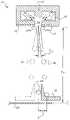
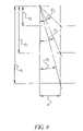
- FIG. 1is a schematic illustration of a liquid emission device according to the present invention
- FIG. 2is a schematic illustration of the liquid emission device configured as a continuous ink jet print head and printing system
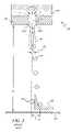
- FIG. 3is a cross-sectional view of one nozzle from a prior art nozzle array showing d 1 (distance to print medium) and ⁇ 1 (angle of deflection);
- FIG. 4is a top view of a nozzle having an asymmetric heater positioned around the nozzle
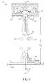
- FIG. 5is a cross-sectional view of one nozzle incorporating one embodiment of the present invention showing d 2 and ⁇ 2 ;
- FIG. 6is a cross-sectional view of one nozzle incorporating another embodiment of the present invention.
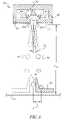
- FIG. 7is a cross-sectional view of one nozzle incorporating a preferred embodiment of the present invention showing d 3 and ⁇ 3 ;
- FIG. 8is a graph illustrating the relationships between d 1 –d 3 , ⁇ 1 – ⁇ 3 , and A;
- FIG. 9is a perspective top view of the liquid emission device according to the present invention.
- FIG. 10is a top view of the liquid emission device according to the present invention.
- FIG. 11is a bottom view of the liquid emission device according to the present invention.
- FIG. 12is a cross-sectional side view of one ejection mechanism of the liquid emission device shown in FIG. 11 as shown along line 12 — 12 ;
- FIG. 13is a cross-sectional side view of one ejection mechanism of the liquid emission device shown in FIG. 12 as shown along line 13 — 13 ;
- FIG. 14is a cross-sectional side view of one ejection mechanism of the liquid emission device shown in FIG. 11 as shown along line 14 — 14 ;
- FIG. 15is a cross-sectional bottom view of one ejection mechanism of the liquid emission device shown in FIG. 11 as shown along line 15 — 15 ;
- FIG. 16is an alternative embodiment of a drop forming mechanism
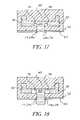
- FIGS. 17–20illustrate operation of the liquid emission device configured as a drop on demand print head.
- the present inventionprovides a liquid emission device and a method of operating the same.
- the most familiar of such devicesare used as print heads in inkjet printing systems.
- the liquid emission device described hereincan be operated in a continuous mode and/or in a drop-on-demand mode.
- liquidrefers to any material that can be ejected by the liquid emission device described below.
- FIG. 1a schematic representation of a liquid emission device 10 , such as an inkjet printer, is shown.
- the systemincludes a source 12 of data (say, image data) which provides signals that are interpreted by a controller 14 as being commands to emit drops.
- Controller 14outputs signals to a source 16 of electrical energy pulses which are inputted to the liquid emission device, for example, an inkjet print head 18 .
- liquidfor example, ink
- liquid emission device 10includes a plurality of ejection mechanisms 22 .
- print head 18 of liquid emission device 10is shown configured as a continuous ink jet printer system.
- Print head 18includes a plurality of ejection mechanisms 22 forming an array of nozzles with each nozzle of the array being associated with a drop forming mechanism (for example, nozzle heater(s) 24 ).
- Print head 18also houses heater control circuits 26 (shown schematically in FIG. 4 ) which process signals from controller 14 .
- Heater control circuits 26take data from the image memory 12 , and send time-sequenced electrical pulses to the array of nozzle heaters 24 .
- ink delivery channel 30shows arrows 34 that depict a substantially vertical flow pattern of ink headed into nozzle bore 36 .
- wall 38which serves, inter alia, to insulate the ink in the channel 30 from heat generated by the nozzle heater sections 24 a / 24 a ′ (described below). Wall 38 may also be referred to as an “orifice membrane.”
- An ink stream 40forms from a meniscus of ink initially leaving the nozzle bore 36 . At a distance below the nozzle bore 36 ink stream 40 breaks into a plurality of drops 42 , 44 .
- Heater 24has two sections (heater sections 24 a and 24 a ′). Each section 24 a and 24 a ′ covers approximately one half of the nozzle bore opening 36 .
- heater sectionscan vary in number and sectional design.
- One sectionprovides a common connection G, and isolated connection P. The other has G′ and P′ respectively.
- Asymmetrical application of heatmerely means applying electrical current to one or the other section of the heater independently. By so doing, the heat will deflect the ink stream 40 , and deflect the drops 42 , for example, away from the particular source of the heat.
- the ink drops 42are deflected at an angle ⁇ 1 (in FIG. 3 ) and will travel a vertical distance d 1 to gutter 32 (or onto recording media 20 ) from print head 18 .
- a distance “A”which distance defines the space between where the deflection angle ⁇ 1 would place the deflected drops 42 in gutter 32 or on recording medium 20 and where the drops 44 would have landed without deflection.
- the streamdeflects in a direction anyway from the application of heat.
- the ink gutter 32is configured to catch deflected ink droplets 42 while allowing undeflected drop 44 to reach a recording medium.
- An alternative embodiment of the present inventioncould reorient ink gutter (or catcher) 32 to be placed so as to catch undeflected drops 44 while allowing deflected drops 42 to reach the recording medium 20 .
- the ink in the delivery channelemanates from pressurized reservoir 28 (shown in FIG. 2 ) leaving the ink in the channel under pressure.
- pressurized reservoir 28shown in FIG. 2
- the ink pressure suitable for optimal operationwould depend upon a number of factors, particularly geometry and thermal properties of the nozzles and thermal properties of the ink.
- a constant pressurecan be achieved by employing an ink pressure regulator (not shown).
- the lateral course of ink flow patterns 46 in the ink delivery channel 30are enhanced by, a geometric obstruction 48 , placed in the delivery channel 30 , just below the nozzle bore 50 .
- This lateral flow enhancing obstruction 48can be varied in size, shape and position, and serves to improve the deflection, based upon the lateralness of the flow and can therefore reduce the dependence upon ink properties (i.e. surface tension, density, viscosity, thermal conductivity, specific heat, etc.), nozzle geometry, and nozzle thermal properties while providing greater degree of control and improved image quality.
- the obstruction 48has a lateral wall parallel to the reservoir side of wall 52 , and cross sectional shapes such as squares, rectangles, triangles (shown in FIG. 6 with like features being represented using like reference symbols), etc.
- Wall 52can serve to insulate portions of ejection mechanism 22 in a manner similar to, or identical to, wall 38 (discussed above).
- Ejection mechanism 22can include additional material layer(s) 53 stacked on wall 52 .
- Layer(s) 53can also serve to insulate other portions of mechanism from the heat generated by heater 24 .
- the deflection enhancementmay be seen by comparing for example the margins of difference between ⁇ 1 of FIG. 3 and ⁇ 2 of FIG. 5 .
- This increased stream deflectionenables improvements in drop placement (and thus image quality) by allowing the recording medium 20 to be placed closer to the print head 18 (d 2 is less than d 1 ) while preserving the other system level tolerances (i.e. spacing, alignment etc.) for example see distance A.
- the orifice membrane or wall 52can also be thinner. We have found that a thinner wall provides additional enhancement in deflection which, in turn, serves to lessen the amount of heat needed per degree of the angle of deflection ⁇ 2 .
- Ejection mechanism 22can include additional material layer(s) 53 stacked on wall 52 .
- Layer(s) 53can also serve to insulate other portions of mechanism from the heat generated by heater 24 .
- the distance d 3 to print medium 20is again lessened per degree of heat because deflection angle ⁇ 3 can be increased per unit temperature.
- FIG. 8shows the relationship of a constant drop placement A as distances to the print media d 1 , d 2 , and d 3 become less and less and as deflection angles ⁇ 1 , ⁇ 2 , and ⁇ 3 become increasingly larger.
- print head 18 of liquid emission device 10includes a plurality of ejection mechanisms 22 positioned in a linear array along a length dimension 58 of print head 18 .
- Ejection mechanisms 22can be positioned in other types of arrays, for example, two dimensional arrays in which nozzle bores 56 are aligned in rows or staggered in rows. Other positions known in the art are also permitted.
- Ejection mechanism 22includes a drop forming mechanism operatively associated with a nozzle bore 56 .
- the drop forming mechanismincludes a heater 24 positioned about a nozzle bore 36 . Heater 24 has been described above with reference to FIGS. 3 and 4 .
- Heater 24can be positioned about nozzle bore 36 on a top surface 60 of a material layer, for example, one of layers 52 or 53 . Alternatively, heater 24 can be positioned within a material layer, for example, one of layers 52 or 53 . Print head 18 also includes a width dimension 62 .
- Nozzle bore 56is formed in wall 52 and any additional material layer(s) present, for example, material layer 53 , for each ejection mechanism 22 .
- additional material layer(s) 53are present, the additional layers are stacked on top of one another, as is known in the art and commonly referred to as a dielectric stack.
- Obstruction 48is positioned in delivery channel 30 .
- Obstruction 48can be centered over nozzle bore 56 with a lateral wall 64 that extends perpendicular to nozzle bore 56 as viewed along a plane that is perpendicular to nozzle bore 56 , as shown in FIG. 12 .
- Lateral wall 64is also typically positioned parallel to wall 52 and spaced apart from wall 52 such that delivery channel 30 intersects nozzle bore 56 .
- a surface 66 of wall 64is imperforate which causes fluid in delivery channel 30 to flow around obstruction 48 to arrive at and pass through nozzle bore 56 .
- Imperforate surface 66at least partially creates lateral flow 54 when ejection mechanism 22 is operated in a continuous manner, as described above.
- Imperforate surface 66also at least partially creates ejection chamber 68 when ejection mechanism 22 is operated in a drop on demand manner, described below.
- a vertical wall or walls 70 of obstruction 48is positioned in delivery channel 30 at a location relative to nozzle bore 56 that causes surface 66 to overlap nozzle bore 56 . This helps to further define ejection chamber 68 and/or create lateral flow 54 .
- vertical wall(s) 70can be located such that surface 66 extends through the diameter of nozzle bore 56 , as shown in FIGS. 5 and 6 .
- Heater 24is operatively associated with nozzle bore 56 and in FIG. 12 is shown positioned on an outer surface of material layer 53 . However, as described above, heater 24 can be located in other areas as long as heater 24 is operatively associated with nozzle bore 56 . These other areas can include, for example, on a surface of wall 52 , within wall 52 , partially within wall 52 , partially within material layer 53 , within material layer 53 , etc. Additional heater(s) 24 can be included within ejection chamber 68 . For example, heater(s) 24 can be positioned on obstruction 48 .
- FIG. 13another cross-sectional view of thermally actuated drop ejection mechanism 22 is shown.
- print head 18is shown including a plurality of ejection mechanisms 22 .
- Delivery channel 30supplies liquid (for example, ink) from source 28 through nozzle bores 56 .
- An obstruction 48is positioned in delivery channel 30 relative to each nozzle bore 56 , as described above.
- each ejection mechanism 22includes an individual obstruction 48 .
- Obstruction 48is supported by wall(s) 72 . Typically, this is accomplished by integrally forming each obstruction 48 with wall(s) 72 during the ejection mechanism 22 fabrication process.
- obstruction 48can be supported relative to nozzle bore 56 is any known manner provided delivery channel 30 has access to nozzle bore 56 .
- wall(s) 72are positioned on opposing sides of nozzle bore 56 perpendicular to the length dimension 58 of print head 18 .
- Wall(s) 72are also typically positioned parallel to the width dimension 62 of print head 18 .
- wall(s) 72can be positioned at other angles relative to the length dimension 58 and width dimension 62 depending on the location pattern of each nozzle bore 56 .
- FIG. 14another cross-sectional view of ejection mechanism 22 is shown.
- wall 72does not extend to wall 52 on the side of wall 52 opposite nozzle bore 56 , but does extend to wall 52 on the side of wall 52 that includes nozzle bore 56 .
- delivery channel 30has access to multiple nozzle bores 56 while the location of wall(s) 72 helps to define ejection mechanism 22 .
- the positioning of wall(s) 72reduces problems that typically occur when multiple nozzle bores share a common delivery channel (nozzle to nozzle cross talk, etc.) while still providing source 28 with access to a plurality of nozzle bores 56 through delivery channel 30 .
- FIG. 15another cross-sectional view of ejection mechanism 22 is shown with like features being represented using like reference signs.
- the cross-sectional view of ejection mechanism 22is the same cross-sectional view of ejection mechanism 22 shown in FIGS. 1 and 7 above and FIGS. 17–20 below.
- heater 74has an annular portion 76 and is positioned around nozzle bore 56 .
- Heater 74also has a common connection G and a connection P connected to annular portion 76 .
- heater 74is actuated as a whole.
- Controller 14outputs a signal to source 16 that causes source 16 to deliver an actuation pulse to heater 24 (or 74 ).
- the actuation of heater 24 (or 74 )causes a portion of the fluid (for example, ink) typically maintained under a slight negative pressure in ejection chamber 68 to vaporize forming vapor bubble(s) 78 .
- Vapor bubble(s) 78expands forcing fluid in ejection chamber 68 to be ejected through nozzle bore 56 in the form of a drop 80 .
- the direction of vapor bubble(s) 78 expansionis opposite to the direction of drop 80 ejection.
- Vapor bubble(s) 78collapse after heater 24 (or 74 ) is de-energized. This allows delivery channels 30 to refill ejection chamber 68 . The process is repeated when an additional fluid drop(s) is desired.
- vapor bubble(s) 78expand at least partially sealing ejection chamber 68 from delivery channels 30 .
- the expansion of vapor bubble(s) 78also forces fluid in ejection chamber 68 to be ejected through nozzle bore 56 in the form of a drop 80 .
- the direction of vapor bubble(s) 78 expansionis opposite to the direction of drop 80 ejection.
- vapor bubble(s) 78expand and contact obstruction 48 (or a portion of wall 52 ) sealing ejection chamber 68 from delivery channels 30 .
- the expansion of vapor bubble(s) 78also forces fluid in ejection chamber 68 to be ejected through nozzle bore 56 in the form of a drop 80 .
- the direction of vapor bubble(s) 78 expansionis opposite to the direction of drop 80 ejection.
- Vapor bubble(s) 78collapse after heater 24 (or 74 ) is de-energized. This allows delivery channels 30 to refill ejection chamber 68 . The process is repeated when an additional fluid drop(s) is desired.
- Heater 24 (or 74 ) activation pulsecan take the shape of any wave form (including period, amplitude, etc.) known in the industry.
- heater 24 (or 74 ) activation pulsecan be shaped like one of the waves forms, or a combination of the wave forms, disclosed in U.S. Pat. No. 4,490,728, issued to Vaught et al. on Dec. 25, 1984.
- other wave form shapesare also possible.
- ejection mechanism 22can be fabricated such that one or more delivery channels 30 feed ejection chamber 68 , it has been discovered that two delivery channels 30 adequately allow ejection chamber 68 to be refilled without sacrificing fluid ejection speeds while reducing nozzle to nozzle cross talk.
- alternative embodiments of ejection mechanism 22can include more or less delivery channels 30 feeding ejection chamber 68 depending on the application specifically contemplated for ejection mechanism 22 .
- heater 24having individually actuateable sections 24 a and 24 a ′ as the drop forming mechanism.
- Heater section 24 ais positioned to seal off one delivery channel 30 when section 24 a is activated while heater section 24 a ′ is positioned to seal off the other delivery channel 30 when section 24 a ′ is activated.
- Ejection mechanism 22was fabricated using known CMOS and/or MEMS fabrication techniques.
- Ejection mechanism 22included a nozzle bore 56 (having a diameter of approximately 10 microns) and a heater 24 (or 74 ) (having a width of approximately 2 microns) positioned approximately 0.6 microns from nozzle bore 56 .
- Heater 24 (or 74 )was positioned on wall (or “orifice membrane”) 52 (having a thickness of approximately 1.5 microns).
- Obstruction 48 in conjunction with walls 52formed ejection chamber 68 .
- Ejection chamber 68had a height of approximately 4 microns, the distance between wall 52 and obstruction 48 , and a width of approximately 30 microns, the distance between delivery channels or the width of obstruction 48 ).
- Ejection chamber 68was in fluid communication with two delivery channels 30 (each delivery channel having dimensions of approximately 30 microns ⁇ 120 microns).
- Experimental ejection mechanism 22was operated in the manner described above.
- Heater 24(or 74 , a 234 ohm heater) was supplied through a cable with a 6 volt electrical pulse having a duration of approximately 2.8 microseconds causing a drop of approximately 1 pico-liter to be ejected through nozzle bore 56 .
- the energy required to accomplish thiswas approximately 0.4 micro-joules.
Landscapes
- Particle Formation And Scattering Control In Inkjet Printers (AREA)
Abstract
Description
Claims (31)
Priority Applications (1)
| Application Number | Priority Date | Filing Date | Title |
|---|---|---|---|
| US10/706,199US6986566B2 (en) | 1999-12-22 | 2003-11-12 | Liquid emission device |
Applications Claiming Priority (3)
| Application Number | Priority Date | Filing Date | Title |
|---|---|---|---|
| US09/470,638US6497510B1 (en) | 1999-12-22 | 1999-12-22 | Deflection enhancement for continuous ink jet printers |
| US10/273,916US6761437B2 (en) | 1999-12-22 | 2002-10-18 | Apparatus and method of enhancing fluid deflection in a continuous ink jet printhead |
| US10/706,199US6986566B2 (en) | 1999-12-22 | 2003-11-12 | Liquid emission device |
Related Parent Applications (1)
| Application Number | Title | Priority Date | Filing Date |
|---|---|---|---|
| US10/273,916Continuation-In-PartUS6761437B2 (en) | 1999-12-22 | 2002-10-18 | Apparatus and method of enhancing fluid deflection in a continuous ink jet printhead |
Publications (2)
| Publication Number | Publication Date |
|---|---|
| US20040179069A1 US20040179069A1 (en) | 2004-09-16 |
| US6986566B2true US6986566B2 (en) | 2006-01-17 |
Family
ID=32965241
Family Applications (1)
| Application Number | Title | Priority Date | Filing Date |
|---|---|---|---|
| US10/706,199Expired - Fee RelatedUS6986566B2 (en) | 1999-12-22 | 2003-11-12 | Liquid emission device |
Country Status (1)
| Country | Link |
|---|---|
| US (1) | US6986566B2 (en) |
Cited By (2)
| Publication number | Priority date | Publication date | Assignee | Title |
|---|---|---|---|---|
| US20070052760A1 (en)* | 2002-11-23 | 2007-03-08 | Silverbrook Research Pty Ltd | Printhead with heater suspended parallel to plane of nozzle |
| US20070279467A1 (en)* | 2006-06-02 | 2007-12-06 | Michael Thomas Regan | Ink jet printing system for high speed/high quality printing |
Families Citing this family (6)
| Publication number | Priority date | Publication date | Assignee | Title |
|---|---|---|---|---|
| US7419250B2 (en)* | 1999-10-15 | 2008-09-02 | Silverbrook Research Pty Ltd | Micro-electromechanical liquid ejection device |
| EP1121249B1 (en) | 1998-10-16 | 2007-07-25 | Silverbrook Research Pty. Limited | Process of forming a nozzle for an inkjet printhead |
| US7658478B2 (en) | 2004-10-04 | 2010-02-09 | Kodak Graphic Communications Canada Company | Non-conductive fluid droplet forming apparatus and method |
| US20090033727A1 (en)* | 2007-07-31 | 2009-02-05 | Anagnostopoulos Constantine N | Lateral flow device printhead with internal gutter |
| EP2411133B1 (en)* | 2009-03-25 | 2013-12-18 | Eastman Kodak Company | Droplet generator |
| JP2015214036A (en)* | 2014-05-08 | 2015-12-03 | 株式会社日立産機システム | Inkjet recording device |
Citations (48)
| Publication number | Priority date | Publication date | Assignee | Title |
|---|---|---|---|---|
| US1941001A (en) | 1929-01-19 | 1933-12-26 | Rca Corp | Recorder |
| US3373437A (en) | 1964-03-25 | 1968-03-12 | Richard G. Sweet | Fluid droplet recorder with a plurality of jets |
| US3416153A (en) | 1965-10-08 | 1968-12-10 | Hertz | Ink jet recorder |
| US3878519A (en) | 1974-01-31 | 1975-04-15 | Ibm | Method and apparatus for synchronizing droplet formation in a liquid stream |
| US3893623A (en) | 1967-12-28 | 1975-07-08 | Ibm | Fluid jet deflection by modulation and coanda selection |
| US4346387A (en) | 1979-12-07 | 1982-08-24 | Hertz Carl H | Method and apparatus for controlling the electric charge on droplets and ink-jet recorder incorporating the same |
| US4490728A (en) | 1981-08-14 | 1984-12-25 | Hewlett-Packard Company | Thermal ink jet printer |
| US4580149A (en) | 1985-02-19 | 1986-04-01 | Xerox Corporation | Cavitational liquid impact printer |
| EP0308272A1 (en) | 1987-09-17 | 1989-03-22 | Hewlett-Packard Company | Multi-chamber ink jet recording head for color use |
| US4847630A (en) | 1987-12-17 | 1989-07-11 | Hewlett-Packard Company | Integrated thermal ink jet printhead and method of manufacture |
| EP0354982A1 (en) | 1988-06-14 | 1990-02-21 | Hewlett-Packard Company | A process for producing successive droplets of ink of different sizes |
| US4982199A (en) | 1988-12-16 | 1991-01-01 | Hewlett-Packard Company | Method and apparatus for gray scale printing with a thermal ink jet pen |
| US5016024A (en) | 1990-01-09 | 1991-05-14 | Hewlett-Packard Company | Integral ink jet print head |
| EP0474472A1 (en) | 1990-09-04 | 1992-03-11 | Xerox Corporation | Thermal ink jet printheads |
| US5109234A (en) | 1990-09-14 | 1992-04-28 | Hewlett-Packard Company | Printhead warming method to defeat wait-time banding |
| JPH06183029A (en) | 1992-06-23 | 1994-07-05 | Seiko Epson Corp | Printer employing ink jet line recording head |
| US5502471A (en) | 1992-04-28 | 1996-03-26 | Eastman Kodak Company | System for an electrothermal ink jet print head |
| EP0805036A2 (en) | 1996-04-30 | 1997-11-05 | SCITEX DIGITAL PRINTING, Inc. | Top feed droplet generator |
| US5734395A (en) | 1993-01-06 | 1998-03-31 | Seiko Epson Corporation | Ink jet head |
| US5746373A (en) | 1995-02-22 | 1998-05-05 | Fuji Photo Film Co., Ltd. | Liquid injection apparatus |
| US5760804A (en) | 1990-05-21 | 1998-06-02 | Eastman Kodak Company | Ink-jet printing head for a liquid-jet printing device operating on the heat converter principle and process for making it |
| US5841452A (en) | 1991-01-30 | 1998-11-24 | Canon Information Systems Research Australia Pty Ltd | Method of fabricating bubblejet print devices using semiconductor fabrication techniques |
| US5886716A (en) | 1994-08-13 | 1999-03-23 | Eastman Kodak Company | Method and apparatus for variation of ink droplet velocity and droplet mass in thermal ink-jet print heads |
| EP0911167A2 (en) | 1997-10-17 | 1999-04-28 | Eastman Kodak Company | Continuous ink jet printer with binary electrostatic deflection |
| US5966154A (en)* | 1997-10-17 | 1999-10-12 | Eastman Kodak Company | Graphic arts printing plate production by a continuous jet drop printing with asymmetric heating drop deflection |
| US6019457A (en) | 1991-01-30 | 2000-02-01 | Canon Information Systems Research Australia Pty Ltd. | Ink jet print device and print head or print apparatus using the same |
| US6022099A (en) | 1997-01-21 | 2000-02-08 | Eastman Kodak Company | Ink printing with drop separation |
| US6023091A (en) | 1995-11-30 | 2000-02-08 | Motorola, Inc. | Semiconductor heater and method for making |
| US6045214A (en)* | 1997-03-28 | 2000-04-04 | Lexmark International, Inc. | Ink jet printer nozzle plate having improved flow feature design and method of making nozzle plates |
| US6079821A (en) | 1997-10-17 | 2000-06-27 | Eastman Kodak Company | Continuous ink jet printer with asymmetric heating drop deflection |
| US6102530A (en) | 1998-01-23 | 2000-08-15 | Kim; Chang-Jin | Apparatus and method for using bubble as virtual valve in microinjector to eject fluid |
| US6193344B1 (en) | 1991-08-01 | 2001-02-27 | Canon Kabushiki Kaisha | Ink jet recording apparatus having temperature control function |
| US6273553B1 (en) | 1998-01-23 | 2001-08-14 | Chang-Jin Kim | Apparatus for using bubbles as virtual valve in microinjector to eject fluid |
| US6296350B1 (en) | 1997-03-25 | 2001-10-02 | Lexmark International, Inc. | Ink jet printer having driver circuit for generating warming and firing pulses for heating elements |
| US6331039B1 (en) | 1994-07-29 | 2001-12-18 | Canon Kabushiki Kaisha | Ink jet recording apparatus and method with modulatable driving pulse width |
| US6382782B1 (en) | 2000-12-29 | 2002-05-07 | Eastman Kodak Company | CMOS/MEMS integrated ink jet print head with oxide based lateral flow nozzle architecture and method of forming same |
| US6412928B1 (en) | 2000-12-29 | 2002-07-02 | Eastman Kodak Company | Incorporation of supplementary heaters in the ink channels of CMOS/MEMS integrated ink jet print head and method of forming same |
| US6422677B1 (en) | 1999-12-28 | 2002-07-23 | Xerox Corporation | Thermal ink jet printhead extended droplet volume control |
| US20020113843A1 (en) | 2001-02-22 | 2002-08-22 | Eastman Kodak Company | CMOS/MEMS integrated ink jet print head and method of forming same |
| US6439703B1 (en) | 2000-12-29 | 2002-08-27 | Eastman Kodak Company | CMOS/MEMS integrated ink jet print head with silicon based lateral flow nozzle architecture and method of forming same |
| US6439691B1 (en) | 2001-03-15 | 2002-08-27 | Samsung Electronics, Co., Ltd. | Bubble-jet type ink-jet printhead with double heater |
| US6460961B2 (en) | 2000-07-24 | 2002-10-08 | Samsung Electronics Co., Ltd. | Heater of bubble-jet type ink-jet printhead for gray scale printing and manufacturing method thereof |
| US6471338B2 (en) | 2001-01-19 | 2002-10-29 | Benq Corporation | Microinjector head having driver circuitry thereon and method for making the same |
| US6497510B1 (en) | 1999-12-22 | 2002-12-24 | Eastman Kodak Company | Deflection enhancement for continuous ink jet printers |
| US6554410B2 (en) | 2000-12-28 | 2003-04-29 | Eastman Kodak Company | Printhead having gas flow ink droplet separation and method of diverging ink droplets |
| US6561625B2 (en) | 2000-12-15 | 2003-05-13 | Samsung Electronics Co., Ltd. | Bubble-jet type ink-jet printhead and manufacturing method thereof |
| US6561626B1 (en) | 2001-12-18 | 2003-05-13 | Samsung Electronics Co., Ltd. | Ink-jet print head and method thereof |
| US6588888B2 (en) | 2000-12-28 | 2003-07-08 | Eastman Kodak Company | Continuous ink-jet printing method and apparatus |
- 2003
- 2003-11-12USUS10/706,199patent/US6986566B2/ennot_activeExpired - Fee Related
Patent Citations (49)
| Publication number | Priority date | Publication date | Assignee | Title |
|---|---|---|---|---|
| US1941001A (en) | 1929-01-19 | 1933-12-26 | Rca Corp | Recorder |
| US3373437A (en) | 1964-03-25 | 1968-03-12 | Richard G. Sweet | Fluid droplet recorder with a plurality of jets |
| US3416153A (en) | 1965-10-08 | 1968-12-10 | Hertz | Ink jet recorder |
| US3893623A (en) | 1967-12-28 | 1975-07-08 | Ibm | Fluid jet deflection by modulation and coanda selection |
| US3878519A (en) | 1974-01-31 | 1975-04-15 | Ibm | Method and apparatus for synchronizing droplet formation in a liquid stream |
| US4346387A (en) | 1979-12-07 | 1982-08-24 | Hertz Carl H | Method and apparatus for controlling the electric charge on droplets and ink-jet recorder incorporating the same |
| US4490728A (en) | 1981-08-14 | 1984-12-25 | Hewlett-Packard Company | Thermal ink jet printer |
| US4580149A (en) | 1985-02-19 | 1986-04-01 | Xerox Corporation | Cavitational liquid impact printer |
| EP0308272A1 (en) | 1987-09-17 | 1989-03-22 | Hewlett-Packard Company | Multi-chamber ink jet recording head for color use |
| US4847630A (en) | 1987-12-17 | 1989-07-11 | Hewlett-Packard Company | Integrated thermal ink jet printhead and method of manufacture |
| EP0354982A1 (en) | 1988-06-14 | 1990-02-21 | Hewlett-Packard Company | A process for producing successive droplets of ink of different sizes |
| US4982199A (en) | 1988-12-16 | 1991-01-01 | Hewlett-Packard Company | Method and apparatus for gray scale printing with a thermal ink jet pen |
| US5016024A (en) | 1990-01-09 | 1991-05-14 | Hewlett-Packard Company | Integral ink jet print head |
| US5760804A (en) | 1990-05-21 | 1998-06-02 | Eastman Kodak Company | Ink-jet printing head for a liquid-jet printing device operating on the heat converter principle and process for making it |
| EP0474472A1 (en) | 1990-09-04 | 1992-03-11 | Xerox Corporation | Thermal ink jet printheads |
| US5109234A (en) | 1990-09-14 | 1992-04-28 | Hewlett-Packard Company | Printhead warming method to defeat wait-time banding |
| US6019457A (en) | 1991-01-30 | 2000-02-01 | Canon Information Systems Research Australia Pty Ltd. | Ink jet print device and print head or print apparatus using the same |
| US5841452A (en) | 1991-01-30 | 1998-11-24 | Canon Information Systems Research Australia Pty Ltd | Method of fabricating bubblejet print devices using semiconductor fabrication techniques |
| US6193344B1 (en) | 1991-08-01 | 2001-02-27 | Canon Kabushiki Kaisha | Ink jet recording apparatus having temperature control function |
| US5502471A (en) | 1992-04-28 | 1996-03-26 | Eastman Kodak Company | System for an electrothermal ink jet print head |
| JPH06183029A (en) | 1992-06-23 | 1994-07-05 | Seiko Epson Corp | Printer employing ink jet line recording head |
| US5734395A (en) | 1993-01-06 | 1998-03-31 | Seiko Epson Corporation | Ink jet head |
| US6331039B1 (en) | 1994-07-29 | 2001-12-18 | Canon Kabushiki Kaisha | Ink jet recording apparatus and method with modulatable driving pulse width |
| US5886716A (en) | 1994-08-13 | 1999-03-23 | Eastman Kodak Company | Method and apparatus for variation of ink droplet velocity and droplet mass in thermal ink-jet print heads |
| US5746373A (en) | 1995-02-22 | 1998-05-05 | Fuji Photo Film Co., Ltd. | Liquid injection apparatus |
| US6023091A (en) | 1995-11-30 | 2000-02-08 | Motorola, Inc. | Semiconductor heater and method for making |
| EP0805036A2 (en) | 1996-04-30 | 1997-11-05 | SCITEX DIGITAL PRINTING, Inc. | Top feed droplet generator |
| US6022099A (en) | 1997-01-21 | 2000-02-08 | Eastman Kodak Company | Ink printing with drop separation |
| US6296350B1 (en) | 1997-03-25 | 2001-10-02 | Lexmark International, Inc. | Ink jet printer having driver circuit for generating warming and firing pulses for heating elements |
| US6045214A (en)* | 1997-03-28 | 2000-04-04 | Lexmark International, Inc. | Ink jet printer nozzle plate having improved flow feature design and method of making nozzle plates |
| US5966154A (en)* | 1997-10-17 | 1999-10-12 | Eastman Kodak Company | Graphic arts printing plate production by a continuous jet drop printing with asymmetric heating drop deflection |
| US6079821A (en) | 1997-10-17 | 2000-06-27 | Eastman Kodak Company | Continuous ink jet printer with asymmetric heating drop deflection |
| EP0911167A2 (en) | 1997-10-17 | 1999-04-28 | Eastman Kodak Company | Continuous ink jet printer with binary electrostatic deflection |
| US6273553B1 (en) | 1998-01-23 | 2001-08-14 | Chang-Jin Kim | Apparatus for using bubbles as virtual valve in microinjector to eject fluid |
| US6102530A (en) | 1998-01-23 | 2000-08-15 | Kim; Chang-Jin | Apparatus and method for using bubble as virtual valve in microinjector to eject fluid |
| US6497510B1 (en) | 1999-12-22 | 2002-12-24 | Eastman Kodak Company | Deflection enhancement for continuous ink jet printers |
| US6761437B2 (en)* | 1999-12-22 | 2004-07-13 | Eastman Kodak Company | Apparatus and method of enhancing fluid deflection in a continuous ink jet printhead |
| US6422677B1 (en) | 1999-12-28 | 2002-07-23 | Xerox Corporation | Thermal ink jet printhead extended droplet volume control |
| US6460961B2 (en) | 2000-07-24 | 2002-10-08 | Samsung Electronics Co., Ltd. | Heater of bubble-jet type ink-jet printhead for gray scale printing and manufacturing method thereof |
| US6561625B2 (en) | 2000-12-15 | 2003-05-13 | Samsung Electronics Co., Ltd. | Bubble-jet type ink-jet printhead and manufacturing method thereof |
| US6588888B2 (en) | 2000-12-28 | 2003-07-08 | Eastman Kodak Company | Continuous ink-jet printing method and apparatus |
| US6554410B2 (en) | 2000-12-28 | 2003-04-29 | Eastman Kodak Company | Printhead having gas flow ink droplet separation and method of diverging ink droplets |
| US6382782B1 (en) | 2000-12-29 | 2002-05-07 | Eastman Kodak Company | CMOS/MEMS integrated ink jet print head with oxide based lateral flow nozzle architecture and method of forming same |
| US6439703B1 (en) | 2000-12-29 | 2002-08-27 | Eastman Kodak Company | CMOS/MEMS integrated ink jet print head with silicon based lateral flow nozzle architecture and method of forming same |
| US6412928B1 (en) | 2000-12-29 | 2002-07-02 | Eastman Kodak Company | Incorporation of supplementary heaters in the ink channels of CMOS/MEMS integrated ink jet print head and method of forming same |
| US6471338B2 (en) | 2001-01-19 | 2002-10-29 | Benq Corporation | Microinjector head having driver circuitry thereon and method for making the same |
| US20020113843A1 (en) | 2001-02-22 | 2002-08-22 | Eastman Kodak Company | CMOS/MEMS integrated ink jet print head and method of forming same |
| US6439691B1 (en) | 2001-03-15 | 2002-08-27 | Samsung Electronics, Co., Ltd. | Bubble-jet type ink-jet printhead with double heater |
| US6561626B1 (en) | 2001-12-18 | 2003-05-13 | Samsung Electronics Co., Ltd. | Ink-jet print head and method thereof |
Non-Patent Citations (3)
| Title |
|---|
| Journal of Microelectromechanical Systems,. vol. 11, No. 5, Oct. 2002, pp. 427-437, by Fan-Gang Tseng, et al. |
| The 12th International Conference on Solid State Sensors, Actuators and Microsystems, Boston, Jun. 8-12, 2003; 2E18.P, pp. 472-475, by by S. S. Baek, et al. |
| The 12th International Conference on Solid State Sensors, Acutators and Microsystems, Boston, Jun. 8-12, 2003; 2C3.5, pp. 380-383, by S. Shin et al. |
Cited By (4)
| Publication number | Priority date | Publication date | Assignee | Title |
|---|---|---|---|---|
| US20070052760A1 (en)* | 2002-11-23 | 2007-03-08 | Silverbrook Research Pty Ltd | Printhead with heater suspended parallel to plane of nozzle |
| US7278716B2 (en)* | 2002-11-23 | 2007-10-09 | Silverbrook Research Pty Ltd | Printhead with heater suspended parallel to plane of nozzle |
| US7771023B2 (en) | 2002-11-23 | 2010-08-10 | Silverbrook Research Pty Ltd | Method of ejecting drops of fluid from an inkjet printhead |
| US20070279467A1 (en)* | 2006-06-02 | 2007-12-06 | Michael Thomas Regan | Ink jet printing system for high speed/high quality printing |
Also Published As
| Publication number | Publication date |
|---|---|
| US20040179069A1 (en) | 2004-09-16 |
Similar Documents
| Publication | Publication Date | Title |
|---|---|---|
| EP1110732B1 (en) | Deflection enhancement for continuous ink jet printers | |
| US6505921B2 (en) | Ink jet apparatus having amplified asymmetric heating drop deflection | |
| US6863385B2 (en) | Continuous ink-jet printing method and apparatus | |
| US7413293B2 (en) | Deflected drop liquid pattern deposition apparatus and methods | |
| US8469494B2 (en) | Flow through drop dispenser including porous member | |
| US8201924B2 (en) | Liquid diverter for flow through drop dispenser | |
| JP2000190508A (en) | Continuous ink jet print head having heater of plurality of segments | |
| US8182073B2 (en) | Flow through dispenser including diverter cooling channel | |
| US8091983B2 (en) | Jet directionality control using printhead nozzle | |
| JP4394418B2 (en) | Fluid ejection device and method for dispensing fluid | |
| KR20130113919A (en) | Fluid ejection device | |
| US8118408B2 (en) | Flow through dispenser having different cross-sectional areas | |
| US6986566B2 (en) | Liquid emission device | |
| EP1112847B1 (en) | Continuous ink jet printer with a notch deflector | |
| CN100581823C (en) | Drop ejection system and method | |
| US7850283B2 (en) | Printhead with liquid flow through device | |
| US8182068B2 (en) | Printhead including dual nozzle structure | |
| US8172364B2 (en) | Flow through dispenser including improved guide structure | |
| US20100277552A1 (en) | Jet directionality control using printhead delivery channel | |
| US8210648B2 (en) | Flow through dispenser including two dimensional array |
Legal Events
| Date | Code | Title | Description |
|---|---|---|---|
| AS | Assignment | Owner name:EASTMAN KODAK COMPANY, NEW YORK Free format text:ASSIGNMENT OF ASSIGNORS INTEREST;ASSIGNORS:DELAMETTER, CHRISTOPHER N.;CHWALEK, JAMES M.;TRAUERNICHT, DAVID P.;AND OTHERS;REEL/FRAME:014706/0711 Effective date:20031107 | |
| FEPP | Fee payment procedure | Free format text:PAYOR NUMBER ASSIGNED (ORIGINAL EVENT CODE: ASPN); ENTITY STATUS OF PATENT OWNER: LARGE ENTITY | |
| FPAY | Fee payment | Year of fee payment:4 | |
| AS | Assignment | Owner name:CITICORP NORTH AMERICA, INC., AS AGENT, NEW YORK Free format text:SECURITY INTEREST;ASSIGNORS:EASTMAN KODAK COMPANY;PAKON, INC.;REEL/FRAME:028201/0420 Effective date:20120215 | |
| AS | Assignment | Owner name:WILMINGTON TRUST, NATIONAL ASSOCIATION, AS AGENT, Free format text:PATENT SECURITY AGREEMENT;ASSIGNORS:EASTMAN KODAK COMPANY;PAKON, INC.;REEL/FRAME:030122/0235 Effective date:20130322 Owner name:WILMINGTON TRUST, NATIONAL ASSOCIATION, AS AGENT, MINNESOTA Free format text:PATENT SECURITY AGREEMENT;ASSIGNORS:EASTMAN KODAK COMPANY;PAKON, INC.;REEL/FRAME:030122/0235 Effective date:20130322 | |
| FPAY | Fee payment | Year of fee payment:8 | |
| AS | Assignment | Owner name:BARCLAYS BANK PLC, AS ADMINISTRATIVE AGENT, NEW YORK Free format text:INTELLECTUAL PROPERTY SECURITY AGREEMENT (SECOND LIEN);ASSIGNORS:EASTMAN KODAK COMPANY;FAR EAST DEVELOPMENT LTD.;FPC INC.;AND OTHERS;REEL/FRAME:031159/0001 Effective date:20130903 Owner name:JPMORGAN CHASE BANK, N.A., AS ADMINISTRATIVE, DELAWARE Free format text:INTELLECTUAL PROPERTY SECURITY AGREEMENT (FIRST LIEN);ASSIGNORS:EASTMAN KODAK COMPANY;FAR EAST DEVELOPMENT LTD.;FPC INC.;AND OTHERS;REEL/FRAME:031158/0001 Effective date:20130903 Owner name:PAKON, INC., NEW YORK Free format text:RELEASE OF SECURITY INTEREST IN PATENTS;ASSIGNORS:CITICORP NORTH AMERICA, INC., AS SENIOR DIP AGENT;WILMINGTON TRUST, NATIONAL ASSOCIATION, AS JUNIOR DIP AGENT;REEL/FRAME:031157/0451 Effective date:20130903 Owner name:EASTMAN KODAK COMPANY, NEW YORK Free format text:RELEASE OF SECURITY INTEREST IN PATENTS;ASSIGNORS:CITICORP NORTH AMERICA, INC., AS SENIOR DIP AGENT;WILMINGTON TRUST, NATIONAL ASSOCIATION, AS JUNIOR DIP AGENT;REEL/FRAME:031157/0451 Effective date:20130903 Owner name:JPMORGAN CHASE BANK, N.A., AS ADMINISTRATIVE, DELA Free format text:INTELLECTUAL PROPERTY SECURITY AGREEMENT (FIRST LIEN);ASSIGNORS:EASTMAN KODAK COMPANY;FAR EAST DEVELOPMENT LTD.;FPC INC.;AND OTHERS;REEL/FRAME:031158/0001 Effective date:20130903 Owner name:BARCLAYS BANK PLC, AS ADMINISTRATIVE AGENT, NEW YO Free format text:INTELLECTUAL PROPERTY SECURITY AGREEMENT (SECOND LIEN);ASSIGNORS:EASTMAN KODAK COMPANY;FAR EAST DEVELOPMENT LTD.;FPC INC.;AND OTHERS;REEL/FRAME:031159/0001 Effective date:20130903 Owner name:BANK OF AMERICA N.A., AS AGENT, MASSACHUSETTS Free format text:INTELLECTUAL PROPERTY SECURITY AGREEMENT (ABL);ASSIGNORS:EASTMAN KODAK COMPANY;FAR EAST DEVELOPMENT LTD.;FPC INC.;AND OTHERS;REEL/FRAME:031162/0117 Effective date:20130903 | |
| FEPP | Fee payment procedure | Free format text:MAINTENANCE FEE REMINDER MAILED (ORIGINAL EVENT CODE: REM.) | |
| LAPS | Lapse for failure to pay maintenance fees | Free format text:PATENT EXPIRED FOR FAILURE TO PAY MAINTENANCE FEES (ORIGINAL EVENT CODE: EXP.) | |
| STCH | Information on status: patent discontinuation | Free format text:PATENT EXPIRED DUE TO NONPAYMENT OF MAINTENANCE FEES UNDER 37 CFR 1.362 | |
| FP | Lapsed due to failure to pay maintenance fee | Effective date:20180117 | |
| AS | Assignment | Owner name:PAKON, INC., NEW YORK Free format text:RELEASE BY SECURED PARTY;ASSIGNOR:JP MORGAN CHASE BANK, N.A., AS ADMINISTRATIVE AGENT;REEL/FRAME:049814/0001 Effective date:20190617 Owner name:KODAK IMAGING NETWORK, INC., NEW YORK Free format text:RELEASE BY SECURED PARTY;ASSIGNOR:JP MORGAN CHASE BANK, N.A., AS ADMINISTRATIVE AGENT;REEL/FRAME:049814/0001 Effective date:20190617 Owner name:QUALEX, INC., NEW YORK Free format text:RELEASE BY SECURED PARTY;ASSIGNOR:JP MORGAN CHASE BANK, N.A., AS ADMINISTRATIVE AGENT;REEL/FRAME:049814/0001 Effective date:20190617 Owner name:FAR EAST DEVELOPMENT LTD., NEW YORK Free format text:RELEASE BY SECURED PARTY;ASSIGNOR:JP MORGAN CHASE BANK, N.A., AS ADMINISTRATIVE AGENT;REEL/FRAME:049814/0001 Effective date:20190617 Owner name:CREO MANUFACTURING AMERICA LLC, NEW YORK Free format text:RELEASE BY SECURED PARTY;ASSIGNOR:JP MORGAN CHASE BANK, N.A., AS ADMINISTRATIVE AGENT;REEL/FRAME:049814/0001 Effective date:20190617 Owner name:KODAK AVIATION LEASING LLC, NEW YORK Free format text:RELEASE BY SECURED PARTY;ASSIGNOR:JP MORGAN CHASE BANK, N.A., AS ADMINISTRATIVE AGENT;REEL/FRAME:049814/0001 Effective date:20190617 Owner name:LASER PACIFIC MEDIA CORPORATION, NEW YORK Free format text:RELEASE BY SECURED PARTY;ASSIGNOR:JP MORGAN CHASE BANK, N.A., AS ADMINISTRATIVE AGENT;REEL/FRAME:049814/0001 Effective date:20190617 Owner name:FPC, INC., NEW YORK Free format text:RELEASE BY SECURED PARTY;ASSIGNOR:JP MORGAN CHASE BANK, N.A., AS ADMINISTRATIVE AGENT;REEL/FRAME:049814/0001 Effective date:20190617 Owner name:EASTMAN KODAK COMPANY, NEW YORK Free format text:RELEASE BY SECURED PARTY;ASSIGNOR:JP MORGAN CHASE BANK, N.A., AS ADMINISTRATIVE AGENT;REEL/FRAME:049814/0001 Effective date:20190617 Owner name:KODAK (NEAR EAST), INC., NEW YORK Free format text:RELEASE BY SECURED PARTY;ASSIGNOR:JP MORGAN CHASE BANK, N.A., AS ADMINISTRATIVE AGENT;REEL/FRAME:049814/0001 Effective date:20190617 Owner name:KODAK REALTY, INC., NEW YORK Free format text:RELEASE BY SECURED PARTY;ASSIGNOR:JP MORGAN CHASE BANK, N.A., AS ADMINISTRATIVE AGENT;REEL/FRAME:049814/0001 Effective date:20190617 Owner name:KODAK AMERICAS, LTD., NEW YORK Free format text:RELEASE BY SECURED PARTY;ASSIGNOR:JP MORGAN CHASE BANK, N.A., AS ADMINISTRATIVE AGENT;REEL/FRAME:049814/0001 Effective date:20190617 Owner name:KODAK PORTUGUESA LIMITED, NEW YORK Free format text:RELEASE BY SECURED PARTY;ASSIGNOR:JP MORGAN CHASE BANK, N.A., AS ADMINISTRATIVE AGENT;REEL/FRAME:049814/0001 Effective date:20190617 Owner name:NPEC, INC., NEW YORK Free format text:RELEASE BY SECURED PARTY;ASSIGNOR:JP MORGAN CHASE BANK, N.A., AS ADMINISTRATIVE AGENT;REEL/FRAME:049814/0001 Effective date:20190617 Owner name:KODAK PHILIPPINES, LTD., NEW YORK Free format text:RELEASE BY SECURED PARTY;ASSIGNOR:JP MORGAN CHASE BANK, N.A., AS ADMINISTRATIVE AGENT;REEL/FRAME:049814/0001 Effective date:20190617 | |
| AS | Assignment | Owner name:FAR EAST DEVELOPMENT LTD., NEW YORK Free format text:RELEASE BY SECURED PARTY;ASSIGNOR:BARCLAYS BANK PLC;REEL/FRAME:052773/0001 Effective date:20170202 Owner name:LASER PACIFIC MEDIA CORPORATION, NEW YORK Free format text:RELEASE BY SECURED PARTY;ASSIGNOR:BARCLAYS BANK PLC;REEL/FRAME:052773/0001 Effective date:20170202 Owner name:NPEC INC., NEW YORK Free format text:RELEASE BY SECURED PARTY;ASSIGNOR:BARCLAYS BANK PLC;REEL/FRAME:052773/0001 Effective date:20170202 Owner name:FPC INC., NEW YORK Free format text:RELEASE BY SECURED PARTY;ASSIGNOR:BARCLAYS BANK PLC;REEL/FRAME:052773/0001 Effective date:20170202 Owner name:QUALEX INC., NEW YORK Free format text:RELEASE BY SECURED PARTY;ASSIGNOR:BARCLAYS BANK PLC;REEL/FRAME:052773/0001 Effective date:20170202 Owner name:KODAK PHILIPPINES LTD., NEW YORK Free format text:RELEASE BY SECURED PARTY;ASSIGNOR:BARCLAYS BANK PLC;REEL/FRAME:052773/0001 Effective date:20170202 Owner name:KODAK (NEAR EAST) INC., NEW YORK Free format text:RELEASE BY SECURED PARTY;ASSIGNOR:BARCLAYS BANK PLC;REEL/FRAME:052773/0001 Effective date:20170202 Owner name:KODAK AMERICAS LTD., NEW YORK Free format text:RELEASE BY SECURED PARTY;ASSIGNOR:BARCLAYS BANK PLC;REEL/FRAME:052773/0001 Effective date:20170202 Owner name:EASTMAN KODAK COMPANY, NEW YORK Free format text:RELEASE BY SECURED PARTY;ASSIGNOR:BARCLAYS BANK PLC;REEL/FRAME:052773/0001 Effective date:20170202 Owner name:KODAK REALTY INC., NEW YORK Free format text:RELEASE BY SECURED PARTY;ASSIGNOR:BARCLAYS BANK PLC;REEL/FRAME:052773/0001 Effective date:20170202 |