US6986543B2 - Automotive interior trim assembly and pad insertion - Google Patents
Automotive interior trim assembly and pad insertionDownload PDFInfo
- Publication number
- US6986543B2 US6986543B2US10/709,698US70969804AUS6986543B2US 6986543 B2US6986543 B2US 6986543B2US 70969804 AUS70969804 AUS 70969804AUS 6986543 B2US6986543 B2US 6986543B2
- Authority
- US
- United States
- Prior art keywords
- cavity
- foam pad
- trim assembly
- substrate member
- pouch
- Prior art date
- Legal status (The legal status is an assumption and is not a legal conclusion. Google has not performed a legal analysis and makes no representation as to the accuracy of the status listed.)
- Expired - Fee Related, expires
Links
- 238000003780insertionMethods0.000titledescription5
- 230000037431insertionEffects0.000titledescription5
- 239000006260foamSubstances0.000claimsabstractdescription79
- 239000000758substrateSubstances0.000claimsabstractdescription47
- 239000000463materialSubstances0.000description17
- 239000010410layerSubstances0.000description10
- 230000000712assemblyEffects0.000description9
- 238000000429assemblyMethods0.000description9
- 238000000034methodMethods0.000description9
- 238000004519manufacturing processMethods0.000description4
- -1polypropylenePolymers0.000description4
- 238000002347injectionMethods0.000description3
- 239000007924injectionSubstances0.000description3
- 229920002554vinyl polymerPolymers0.000description3
- 239000004743PolypropyleneSubstances0.000description2
- XECAHXYUAAWDEL-UHFFFAOYSA-Nacrylonitrile butadiene styreneChemical compoundC=CC=C.C=CC#N.C=CC1=CC=CC=C1XECAHXYUAAWDEL-UHFFFAOYSA-N0.000description2
- 239000004676acrylonitrile butadiene styreneSubstances0.000description2
- 229920000122acrylonitrile butadiene styrenePolymers0.000description2
- 230000008901benefitEffects0.000description2
- 238000007796conventional methodMethods0.000description2
- 229920001971elastomerPolymers0.000description2
- 239000000806elastomerSubstances0.000description2
- 229920001684low density polyethylenePolymers0.000description2
- 239000004702low-density polyethyleneSubstances0.000description2
- 238000000465mouldingMethods0.000description2
- 229920001155polypropylenePolymers0.000description2
- 238000007789sealingMethods0.000description2
- 229920002397thermoplastic olefinPolymers0.000description2
- 125000000391vinyl groupChemical group[H]C([*])=C([H])[H]0.000description2
- PYSRRFNXTXNWCD-UHFFFAOYSA-N3-(2-phenylethenyl)furan-2,5-dioneChemical compoundO=C1OC(=O)C(C=CC=2C=CC=CC=2)=C1PYSRRFNXTXNWCD-UHFFFAOYSA-N0.000description1
- 229920002943EPDM rubberPolymers0.000description1
- 239000004698PolyethyleneSubstances0.000description1
- 239000004820Pressure-sensitive adhesiveSubstances0.000description1
- 229920000147Styrene maleic anhydridePolymers0.000description1
- 230000001070adhesive effectEffects0.000description1
- 239000000956alloySubstances0.000description1
- 229910045601alloyInorganic materials0.000description1
- 230000003247decreasing effectEffects0.000description1
- 239000004744fabricSubstances0.000description1
- 239000006261foam materialSubstances0.000description1
- 239000010985leatherSubstances0.000description1
- 238000012986modificationMethods0.000description1
- 230000004048modificationEffects0.000description1
- 229920003023plasticPolymers0.000description1
- 239000004033plasticSubstances0.000description1
- 239000004417polycarbonateSubstances0.000description1
- 229920000515polycarbonatePolymers0.000description1
- 229920000573polyethylenePolymers0.000description1
- 239000002952polymeric resinSubstances0.000description1
- 239000004800polyvinyl chlorideSubstances0.000description1
- 229920000915polyvinyl chloridePolymers0.000description1
- 239000011347resinSubstances0.000description1
- 229920005989resinPolymers0.000description1
- 239000002344surface layerSubstances0.000description1
- 229920003002synthetic resinPolymers0.000description1
Images

Classifications
- B—PERFORMING OPERATIONS; TRANSPORTING
- B60—VEHICLES IN GENERAL
- B60R—VEHICLES, VEHICLE FITTINGS, OR VEHICLE PARTS, NOT OTHERWISE PROVIDED FOR
- B60R21/00—Arrangements or fittings on vehicles for protecting or preventing injuries to occupants or pedestrians in case of accidents or other traffic risks
- B60R21/02—Occupant safety arrangements or fittings, e.g. crash pads
- B60R21/04—Padded linings for the vehicle interior ; Energy absorbing structures associated with padded or non-padded linings
- B60R21/0428—Padded linings for the vehicle interior ; Energy absorbing structures associated with padded or non-padded linings associated with the side doors or panels, e.g. displaced towards the occupants in case of a side collision
Definitions
- the present inventionpertains generally to automotive interiors and more particularly to trim assemblies for automotive interiors.
- One conventional method of forming a trim assembly with padded materialincludes injecting a foam material between a rigid substrate and a skin layer joined to the substrate.
- a preformed, soft, resilient padis secured to a rigid plastic shell and a pliable skin layer is stretched over the pad and secured to the shell to form the trim assembly.
- trim assemblieshave been manufactured using a two-shot molding process wherein a relatively soft skin layer is formed over a hard substrate material without padding.
- the substrate and skin layerare formed so as to provide a recess or cavity for inserting a resilient padding material that provides a soft feel to the trim assembly.
- the padding materialis secured to a top surface of a rigid pad carrier which facilitates the insertion of the pad material into the cavity.
- a separate closeout or back platethen couples to the substrate to cover the opening to the cavity and encloses the pad carrier and pad material within the cavity. Inserting the pad material into trim assemblies and securing the pad material and pad carrier therein requires additional components that increase the overall manufacturing cost of the trim assemblies.
- the present inventionprovides an automotive interior trim assembly that exhibits a soft feel, but which can be produced in an efficient and cost-effective manner.
- the trim assemblymay be formed as an instrument panel, an armrest, a door panel, a console or other interior trim component that would benefit from having at least some areas which are soft to the touch.
- the trim assemblycomprises a substrate member forming at least part of a structural support of the trim assembly and a flexible skin overlying at least a portion of the substrate member and coupled to the substrate member.
- the substrate and flexible skinare configured to define a cavity having an opening.
- the trim assemblyfurther includes a back plate mountable to the substrate member and adapted to cover the cavity opening.
- a resilient foam pad contained within a pouchis positioned within the cavity to provide a soft feel to the trim assembly.
- the foam padis inserted into the cavity when the foam pad is in a compressed state. This may be done by placing the foam pad within the pouch and placing the foam pad under vacuum. The pouch is then sealed such that the interior of the pouch remains under vacuum and the foam pad remains in a compressed state. The foam pad is then inserted into the cavity while in the compressed state. Once positioned in the cavity, the vacuum is relieved. This may be done by inserting a piercing member through an aperture in the back plate to pierce the pouch thereby relieving the vacuum within the pouch. This causes the foam pad to expand so as to substantially fill the cavity and provide a soft feel to the trim assembly.
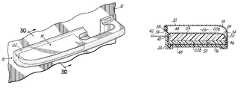
- FIG. 1is a perspective view of an exemplary automotive interior trim assembly according to the present invention, in the form of an armrest;
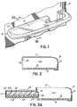
- FIG. 2is a cross-sectional view of the armrest of FIG. 1 , without the foam pad;
- FIGS. 3A–3Eare sequential cross-sectional views illustrating the insertion of a resilient foam pad into the armrest of FIG. 1 according to the present invention.
- an exemplary automotive interior trim assembly of the present inventionin the form of an armrest 10 .
- the armrest 10is attached to a vertical panel 12 within the interior of an automobile, such as a door panel.
- the armrest 10includes a first portion 14 providing a horizontal surface upon which a vehicle occupant may rest their arm. It is often desirable that first portion 14 of armrest 10 provide for a soft feel.
- the armrest 10 of the present inventionincludes a rigid substrate member 16 , a flexible skin layer 18 , a back plate 20 and a resilient foam pad 22 contained within a pouch 24 .
- Substrate member 16comprises a generally planar substrate that forms at least a part of the structural support of the armrest 10 and is adapted to be mounted to the door panel 12 .
- the substrate member 16is generally injection molded and formed from filled or unfilled polypropylene, thermoplastic olefin elastomers, acrylonitrile butadiene styrene, styrene maleic anhydride, polycarbonate/acrylonitrile butadiene styrene alloy, or other suitable materials for forming the rigid substrate member 16 .
- Flexible skin layer 18is disposed over at least a portion of the substrate member 16 and coupled thereto.
- flexible skin 18may be integrally molded to substrate member 16 by a known process such as over molding.
- flexible skin layer 18 and substrate member 16are configured so as to define a cavity 26 having an opening 28 .
- Cavity 26may be generally rectangular having substrate member 16 bounding the bottom of the cavity and flexible skin 18 bounding top and side surfaces of the cavity.
- Flexible skin 18is generally injection molded and may be formed from polyvinyl chloride, thermoplastic olefin elastomers or other suitable materials for forming a flexible skin over the substrate member 16 .
- a back plate 20is mountable to the substrate 16 and is configured to cover the opening 28 to cavity 26 . When back plate 20 is removed or not mounted to substrate 16 , the opening 28 of cavity 26 is accessible.
- Back plate 20may further include a recess 36 and flexible skin 18 may further include a tab 38 such that when back plate 20 is mounted to substrate 16 , tab 38 engages recess 36 to secure back plate 20 in a closed position covering opening 28 .
- Back plate 20further includes an aperture 40 extending through back plate 20 and adapted to permit a piercing member 42 to be inserted through aperture 34 , opening 28 and into cavity 26 .
- the back plate 20is generally injection molded and generally formed from the same or similar materials as is the substrate member 16 .
- a resilient foam pad 22 contained within a pouch 24is positioned in cavity 26 so as to be between the flexible skin 18 and the substrate member 16 and to provide a soft feel to armrest 10 .
- Foam pad 22 and pouch 24are insertable into cavity 26 through opening 28 when back plate 20 is not mounted to substrate 16 .
- Foam pad 20includes a top surface 44 and side surface 46 that abut the underside of top surface 32 and side surface 34 respectively of the flexible skin 18 , and a bottom surface 48 that abuts a top surface 50 of substrate member 16 .
- the pouch 24is sandwiched between the foam pad 22 and the top surface 32 and side surface 34 of the flexible skin 18 and the top surface 50 of substrate 16 .
- Foam pad 20can be die-cut so as to conform to the geometric shape of cavity 26 and may be formed from vinyl nitrile resins as well as one of the polymeric resins, such as EPDM, polypropylene, polyethylene or other suitable materials.
- the foammay be comprised solely of open cell foam or be a combination of open and closed cell foam.
- the foam pad 22may be comprised of a top layer 22 ( a ) made from open cell foam and a bottom layer 22 ( b ) made from a closed cell foam.
- the foam layers 22 ( a ) and 22 ( b )may be bonded together, for instance using a pressure sensitive adhesive, to form the foam pad 22 .
- the foam pad 22may be formed with as much as 100% open cell foam 22 ( a ) or as little as 10% open cell foam 22 ( a ), with the closed cell foam 22 ( b ) making up the remainder of the foam pad 22 .
- the foam padcomprises 75% open cell foam 22 ( a ) and 25% closed cell foam 22 ( b ).
- the closed cell foamprovides some measure of support and rigidity to the foam pad 22 while the open cell foam provides the soft feel.
- the pouch 24is generally formed from thin sheets of material that have sufficient strength to retain the foam pad therein, while being generally gas impermeable.
- the pouchmay be made from vinyl, low density polyethylene (LDPE) or other suitable materials known in the art.
- LDPElow density polyethylene
- the pouchesgenerally have an opening along one end for inserting the foam pad 22 therein.
- the pouch 24is amenable to sealing along the opening of the pouch, such as by heat sealing.
- FIGS. 3A–3Esequentially illustrate the insertion of foam pad 22 within cavity 26 using the pouch/vacuum process.
- pulling a vacuum on a foam pad 22causes the foam pad 22 to compress inwardly, thereby decreasing the size of the foam pad 22 .
- a compressed foam pad 22 in a pouch 24such as compressing foam pad 22 prior to insertion into pouch 24 . While in the compressed state, the pouch 24 is fluidly sealed from the external environment so as to prevent any air from entering the pouch 24 . This maintains the vacuum within the pouch 24 and keeps the foam pad 22 in a compressed state.
- the foam pad 22 and pouch 24 created by the vacuum seal processmay be easily and conveniently inserted through opening 28 and into cavity 26 .
- the foam pad 22is placed on the top surface 50 of substrate 16 so that the bottom surface 48 of the foam pad 22 overlies top surface 50 , as shown in FIG. 3B .
- FIG. 3Cwhen the foam pad 22 and pouch 24 are properly positioned within cavity 26 , the back plate 20 is mounted to substrate 16 and secured to flexible skin 18 by engaging tab 38 with recess 36 thereby closing off opening 28 and securing the foam pad 22 and pouch 24 within the cavity 26 .
- a piercing member 42such as for example, a pin, is then inserted through the aperture 40 in back plate 20 so as to pierce or form a hole in pouch 24 , as shown in FIG. 3D .
- the vacuum within pouch 24is relieved allowing air from the external environment to flow into pouch 24 .
- This in turn,causes the foam pad 22 to expand thereby substantially filling cavity 26 and providing a soft feel to the armrest 10 .
- the outer surface 54 of a top portion of pouch 24to the flexible skin 18 along the underside of top surface 32 of flexible skin 18 .
- the outer surface 54 of the pouch 24contacts and adheres to the underside of top surface 32 of flexibly skin 18 .
- the method of inserting the foam pad 22 within cavity 26 using the vacuum sealed pouch 24 as described hereinis advantageous in that the pad carrier of previous armrests is completely eliminated thus reducing the number of components and consequently reducing the cost of manufacturing the trim assembly.
- interior trim assemblyhas been shown and described herein as an armrest 10 , it will be recognized that the interior trim assembly of the present invention may alternatively be formed to create a door trim panel, an instrument panel, a console or other interior components of an automobile.
Landscapes
- Engineering & Computer Science (AREA)
- Mechanical Engineering (AREA)
- Vehicle Interior And Exterior Ornaments, Soundproofing, And Insulation (AREA)
Abstract
Description
Claims (9)
Priority Applications (1)
| Application Number | Priority Date | Filing Date | Title |
|---|---|---|---|
| US10/709,698US6986543B2 (en) | 2004-05-24 | 2004-05-24 | Automotive interior trim assembly and pad insertion |
Applications Claiming Priority (1)
| Application Number | Priority Date | Filing Date | Title |
|---|---|---|---|
| US10/709,698US6986543B2 (en) | 2004-05-24 | 2004-05-24 | Automotive interior trim assembly and pad insertion |
Publications (2)
| Publication Number | Publication Date |
|---|---|
| US20050258666A1 US20050258666A1 (en) | 2005-11-24 |
| US6986543B2true US6986543B2 (en) | 2006-01-17 |
Family
ID=35374505
Family Applications (1)
| Application Number | Title | Priority Date | Filing Date |
|---|---|---|---|
| US10/709,698Expired - Fee RelatedUS6986543B2 (en) | 2004-05-24 | 2004-05-24 | Automotive interior trim assembly and pad insertion |
Country Status (1)
| Country | Link |
|---|---|
| US (1) | US6986543B2 (en) |
Cited By (8)
| Publication number | Priority date | Publication date | Assignee | Title |
|---|---|---|---|---|
| US20060021823A1 (en)* | 2004-07-29 | 2006-02-02 | Nishikawa Rubber Co., Ltd. | Noise isolation sheet |
| US20060117540A1 (en)* | 2004-03-11 | 2006-06-08 | Bailey Charles D | Automotive interior trim assembly and pad insertion |
| US20060152037A1 (en)* | 2005-01-12 | 2006-07-13 | Lear Corporation | Automotive open base foam armrest assembly |
| US20080238121A1 (en)* | 2007-03-29 | 2008-10-02 | Dean Arden Boyce | Acoustic panel assembly |
| WO2010030411A1 (en)* | 2008-09-12 | 2010-03-18 | Faurecia Interior Systems U.S.A., Inc. | Decorative trim and method for making same |
| US8083283B2 (en) | 2010-05-07 | 2011-12-27 | International Automobile Components Group North America, Inc. | Armrest foam bun insert |
| US20190077324A1 (en)* | 2017-09-13 | 2019-03-14 | Ford Global Technologies, Llc | Deployable door panel receptacle for vehicles |
| CN104709185B (en)* | 2013-12-17 | 2019-12-10 | 福特全球技术公司 | Vehicle armrest with structural fabric substrate |
Families Citing this family (7)
| Publication number | Priority date | Publication date | Assignee | Title |
|---|---|---|---|---|
| US7871119B2 (en) | 2004-04-30 | 2011-01-18 | International Automotive Components Group North America, Inc. | Door trim panel with dual density bolster armrest and integrated components |
| US20060029789A1 (en)* | 2004-08-05 | 2006-02-09 | Lear Corporation | Interior vehicle trim panel having dual density spray elastomer and method for making the same |
| US7478854B2 (en) | 2004-10-19 | 2009-01-20 | International Automotive Components Group North America, Inc. | Automotive handle with soft feel and method of making the same |
| US7458604B2 (en) | 2004-10-20 | 2008-12-02 | International Automotive Components Group North America, Inc. | Automotive trim assembly having an integrated airbag door |
| US7284784B2 (en)* | 2005-06-08 | 2007-10-23 | Lear Corporation | Automotive bolster with soft feel and method of making the same |
| CN101646542B (en)* | 2007-01-18 | 2014-08-27 | 约翰逊控制技术公司 | Component having a cushioned region and method for making a component having a cushioned region |
| US10399513B2 (en)* | 2017-04-10 | 2019-09-03 | Toyota Motor Engineering & Manufacturing North America, Inc. | Vehicle doors including door trim assemblies and vehicles including same |
Citations (8)
| Publication number | Priority date | Publication date | Assignee | Title |
|---|---|---|---|---|
| US4919470A (en) | 1987-12-03 | 1990-04-24 | R. Schmidt Gmbh | Motor vehicle door panel |
| US5626382A (en) | 1995-04-03 | 1997-05-06 | Lear Corporation | Molded plastic panel having integrated, localized soft-touch aesthetic feature |
| US5893601A (en)* | 1997-02-18 | 1999-04-13 | Carlberg; Linda L. | Vehicle door top armrest |
| US5902006A (en) | 1995-12-23 | 1999-05-11 | Daimler-Benz Ag | Adjustable shape part for an interior of a motor vehicle |
| US5906409A (en) | 1995-06-06 | 1999-05-25 | Chrysler Corporation | Vehicle door assembly |
| US5951094A (en)* | 1995-12-28 | 1999-09-14 | Nissan Motor Co., Ltd. | Arm rest for a vehicle |
| US6092858A (en) | 1995-07-14 | 2000-07-25 | Nylex Corporation Limited | Moulded interior door panel |
| US6899363B2 (en)* | 2003-02-19 | 2005-05-31 | Lear Corporation | Method of forming a vehicle component |
- 2004
- 2004-05-24USUS10/709,698patent/US6986543B2/ennot_activeExpired - Fee Related
Patent Citations (8)
| Publication number | Priority date | Publication date | Assignee | Title |
|---|---|---|---|---|
| US4919470A (en) | 1987-12-03 | 1990-04-24 | R. Schmidt Gmbh | Motor vehicle door panel |
| US5626382A (en) | 1995-04-03 | 1997-05-06 | Lear Corporation | Molded plastic panel having integrated, localized soft-touch aesthetic feature |
| US5906409A (en) | 1995-06-06 | 1999-05-25 | Chrysler Corporation | Vehicle door assembly |
| US6092858A (en) | 1995-07-14 | 2000-07-25 | Nylex Corporation Limited | Moulded interior door panel |
| US5902006A (en) | 1995-12-23 | 1999-05-11 | Daimler-Benz Ag | Adjustable shape part for an interior of a motor vehicle |
| US5951094A (en)* | 1995-12-28 | 1999-09-14 | Nissan Motor Co., Ltd. | Arm rest for a vehicle |
| US5893601A (en)* | 1997-02-18 | 1999-04-13 | Carlberg; Linda L. | Vehicle door top armrest |
| US6899363B2 (en)* | 2003-02-19 | 2005-05-31 | Lear Corporation | Method of forming a vehicle component |
Cited By (13)
| Publication number | Priority date | Publication date | Assignee | Title |
|---|---|---|---|---|
| US20060117540A1 (en)* | 2004-03-11 | 2006-06-08 | Bailey Charles D | Automotive interior trim assembly and pad insertion |
| US20060021823A1 (en)* | 2004-07-29 | 2006-02-02 | Nishikawa Rubber Co., Ltd. | Noise isolation sheet |
| US20060152037A1 (en)* | 2005-01-12 | 2006-07-13 | Lear Corporation | Automotive open base foam armrest assembly |
| US7240957B2 (en)* | 2005-01-12 | 2007-07-10 | Lear Corporation | Automotive open base foam armrest assembly |
| US20080238121A1 (en)* | 2007-03-29 | 2008-10-02 | Dean Arden Boyce | Acoustic panel assembly |
| US7503429B2 (en)* | 2007-03-29 | 2009-03-17 | Deere & Company | Acoustic panel assembly |
| WO2010030411A1 (en)* | 2008-09-12 | 2010-03-18 | Faurecia Interior Systems U.S.A., Inc. | Decorative trim and method for making same |
| US20100068425A1 (en)* | 2008-09-12 | 2010-03-18 | Faurecia Interior Systems U.S.A., Inc. | Decorative trim and method for making same |
| US7851039B2 (en) | 2008-09-12 | 2010-12-14 | Faurecia Interior Systemns, Inc. | Decorative trim and method for making same |
| US8083283B2 (en) | 2010-05-07 | 2011-12-27 | International Automobile Components Group North America, Inc. | Armrest foam bun insert |
| CN104709185B (en)* | 2013-12-17 | 2019-12-10 | 福特全球技术公司 | Vehicle armrest with structural fabric substrate |
| US20190077324A1 (en)* | 2017-09-13 | 2019-03-14 | Ford Global Technologies, Llc | Deployable door panel receptacle for vehicles |
| US10464493B2 (en)* | 2017-09-13 | 2019-11-05 | Ford Global Technologies, Llc | Deployable door panel receptacle for vehicles |
Also Published As
| Publication number | Publication date |
|---|---|
| US20050258666A1 (en) | 2005-11-24 |
Similar Documents
| Publication | Publication Date | Title |
|---|---|---|
| US6986543B2 (en) | Automotive interior trim assembly and pad insertion | |
| US8530028B2 (en) | Localized deep soft area of a trim panel | |
| EP2106357B1 (en) | Integrated soft center floor console | |
| US7070221B2 (en) | Automotive interior trim component with soft feel | |
| US8071002B2 (en) | Vertical trim panel with integrated stitching | |
| US20020125734A1 (en) | Foam-in-place seal and method | |
| US20080073807A1 (en) | Method of forming a vehicle trim component | |
| EP1682384B1 (en) | Method for making a vehicle panel and vehicle panel | |
| US8083283B2 (en) | Armrest foam bun insert | |
| US20050186388A1 (en) | Automotive interior trim assembly with soft feel | |
| US20060117540A1 (en) | Automotive interior trim assembly and pad insertion | |
| KR101414996B1 (en) | Component having a cushioned region and method for making a component having a cushioned region | |
| US7226113B2 (en) | Armrest insert and corresponding assembly for a vehicle | |
| US7087199B2 (en) | Process for the manufacture of an article covered with a supple insert | |
| KR100776077B1 (en) | How to make vehicle parts and vehicle panels | |
| JP2001138822A (en) | Vehicle interior member with skin and manufacturing method thereof | |
| JP3119348B2 (en) | Automotive interior parts | |
| JP2018039212A (en) | Manufacturing method of vehicle interior member | |
| JP2003117939A (en) | Method for producing skin integrated resin molded article | |
| JPH0464412A (en) | Manufacture of interior automotive trim |
Legal Events
| Date | Code | Title | Description |
|---|---|---|---|
| AS | Assignment | Owner name:LEAR CORPORATION, MICHIGAN Free format text:ASSIGNMENT OF ASSIGNORS INTEREST;ASSIGNOR:REED, RANDY S.;REEL/FRAME:014649/0502 Effective date:20040520 | |
| AS | Assignment | Owner name:JPMORGAN CHASE BANK, N.A., AS GENERAL ADMINISTRATI Free format text:SECURITY AGREEMENT;ASSIGNOR:LEAR CORPORATION;REEL/FRAME:017858/0719 Effective date:20060425 | |
| AS | Assignment | Owner name:INTERNATIONAL AUTOMOTIVE COMPONENTS GROUP NORTH AM Free format text:ASSIGNMENT OF ASSIGNORS INTEREST;ASSIGNOR:LEAR CORPORATION;REEL/FRAME:019215/0727 Effective date:20070427 | |
| REMI | Maintenance fee reminder mailed | ||
| LAPS | Lapse for failure to pay maintenance fees | ||
| STCH | Information on status: patent discontinuation | Free format text:PATENT EXPIRED DUE TO NONPAYMENT OF MAINTENANCE FEES UNDER 37 CFR 1.362 | |
| FP | Lapsed due to failure to pay maintenance fee | Effective date:20100117 | |
| AS | Assignment | Owner name:LEAR CORPORATION, MICHIGAN Free format text:RELEASE BY SECURED PARTY;ASSIGNOR:JPMORGAN CHASE BANK, N.A.;REEL/FRAME:032722/0553 Effective date:20100830 | |
| AS | Assignment | Owner name:LEAR CORPORATION, MICHIGAN Free format text:RELEASE BY SECURED PARTY;ASSIGNOR:JPMORGAN CHASE BANK, N.A., AS AGENT;REEL/FRAME:037731/0918 Effective date:20160104 |