US6986382B2 - Interwoven manifolds for pressure drop reduction in microchannel heat exchangers - Google Patents
Interwoven manifolds for pressure drop reduction in microchannel heat exchangersDownload PDFInfo
- Publication number
- US6986382B2 US6986382B2US10/439,912US43991203AUS6986382B2US 6986382 B2US6986382 B2US 6986382B2US 43991203 AUS43991203 AUS 43991203AUS 6986382 B2US6986382 B2US 6986382B2
- Authority
- US
- United States
- Prior art keywords
- heat exchanger
- fingers
- fluid
- layer
- interface layer
- Prior art date
- Legal status (The legal status is an assumption and is not a legal conclusion. Google has not performed a legal analysis and makes no representation as to the accuracy of the status listed.)
- Expired - Lifetime
Links
- 230000009467reductionEffects0.000titledescription2
- 239000012530fluidSubstances0.000claimsabstractdescription301
- 238000001816coolingMethods0.000claimsabstractdescription26
- 239000011248coating agentSubstances0.000claimsdescription46
- 238000000576coating methodMethods0.000claimsdescription46
- 238000000034methodMethods0.000claimsdescription39
- 238000004891communicationMethods0.000claimsdescription30
- 230000005465channelingEffects0.000claimsdescription8
- 230000005514two-phase flowEffects0.000claimsdescription8
- 239000007788liquidSubstances0.000claimsdescription6
- 230000007704transitionEffects0.000claims3
- 238000003491arrayMethods0.000claims1
- 239000010410layerSubstances0.000description435
- 239000000463materialSubstances0.000description47
- 238000010586diagramMethods0.000description15
- PXHVJJICTQNCMI-UHFFFAOYSA-NNickelChemical compound[Ni]PXHVJJICTQNCMI-UHFFFAOYSA-N0.000description14
- 238000004519manufacturing processMethods0.000description11
- 229910052751metalInorganic materials0.000description10
- 239000002184metalSubstances0.000description10
- XUIMIQQOPSSXEZ-UHFFFAOYSA-NSiliconChemical compound[Si]XUIMIQQOPSSXEZ-UHFFFAOYSA-N0.000description9
- 239000011521glassSubstances0.000description9
- 230000008569processEffects0.000description8
- 229910052710siliconInorganic materials0.000description8
- 239000010703siliconSubstances0.000description8
- 238000012546transferMethods0.000description8
- 229910052759nickelInorganic materials0.000description7
- 239000000126substanceSubstances0.000description7
- 239000012528membraneSubstances0.000description6
- 239000012071phaseSubstances0.000description6
- 239000004033plasticSubstances0.000description6
- 238000005323electroformingMethods0.000description5
- 229910052782aluminiumInorganic materials0.000description4
- XAGFODPZIPBFFR-UHFFFAOYSA-NaluminiumChemical compound[Al]XAGFODPZIPBFFR-UHFFFAOYSA-N0.000description4
- 238000003801millingMethods0.000description4
- 229920000642polymerPolymers0.000description4
- 230000004044responseEffects0.000description4
- RYGMFSIKBFXOCR-UHFFFAOYSA-NCopperChemical compound[Cu]RYGMFSIKBFXOCR-UHFFFAOYSA-N0.000description3
- 239000002131composite materialSubstances0.000description3
- 229910052802copperInorganic materials0.000description3
- 239000010949copperSubstances0.000description3
- 230000007423decreaseEffects0.000description3
- 238000013461designMethods0.000description3
- 238000009826distributionMethods0.000description3
- 238000005530etchingMethods0.000description3
- 238000001746injection mouldingMethods0.000description3
- 239000000758substrateSubstances0.000description3
- VYPSYNLAJGMNEJ-UHFFFAOYSA-NSilicium dioxideChemical compoundO=[Si]=OVYPSYNLAJGMNEJ-UHFFFAOYSA-N0.000description2
- 230000001133accelerationEffects0.000description2
- 230000008901benefitEffects0.000description2
- 230000008859changeEffects0.000description2
- 230000001419dependent effectEffects0.000description2
- 238000009713electroplatingMethods0.000description2
- 238000004049embossingMethods0.000description2
- 230000005496eutecticsEffects0.000description2
- 238000005242forgingMethods0.000description2
- 230000020169heat generationEffects0.000description2
- 238000001459lithographyMethods0.000description2
- 150000002739metalsChemical class0.000description2
- 239000000203mixtureSubstances0.000description2
- 238000000926separation methodMethods0.000description2
- 238000002174soft lithographyMethods0.000description2
- 238000011144upstream manufacturingMethods0.000description2
- BLIQUJLAJXRXSG-UHFFFAOYSA-N1-benzyl-3-(trifluoromethyl)pyrrolidin-1-ium-3-carboxylateChemical compoundC1C(C(=O)O)(C(F)(F)F)CCN1CC1=CC=CC=C1BLIQUJLAJXRXSG-UHFFFAOYSA-N0.000description1
- OKTJSMMVPCPJKN-UHFFFAOYSA-NCarbonChemical compound[C]OKTJSMMVPCPJKN-UHFFFAOYSA-N0.000description1
- VYZAMTAEIAYCRO-UHFFFAOYSA-NChromiumChemical compound[Cr]VYZAMTAEIAYCRO-UHFFFAOYSA-N0.000description1
- 239000004593EpoxySubstances0.000description1
- 239000000853adhesiveSubstances0.000description1
- 230000001070adhesive effectEffects0.000description1
- 239000000956alloySubstances0.000description1
- 229910045601alloyInorganic materials0.000description1
- 238000009835boilingMethods0.000description1
- -1but not limited toSubstances0.000description1
- 238000003486chemical etchingMethods0.000description1
- 238000006243chemical reactionMethods0.000description1
- 229910052804chromiumInorganic materials0.000description1
- 239000011651chromiumSubstances0.000description1
- 239000011247coating layerSubstances0.000description1
- 230000003750conditioning effectEffects0.000description1
- 239000004020conductorSubstances0.000description1
- 238000010276constructionMethods0.000description1
- 238000007796conventional methodMethods0.000description1
- 238000001723curingMethods0.000description1
- 230000003247decreasing effectEffects0.000description1
- 229910003460diamondInorganic materials0.000description1
- 239000010432diamondSubstances0.000description1
- 239000003989dielectric materialSubstances0.000description1
- 238000005553drillingMethods0.000description1
- 230000000694effectsEffects0.000description1
- 230000004907fluxEffects0.000description1
- 239000006260foamSubstances0.000description1
- 230000004927fusionEffects0.000description1
- 229910002804graphiteInorganic materials0.000description1
- 239000010439graphiteSubstances0.000description1
- 230000017525heat dissipationEffects0.000description1
- 238000010438heat treatmentMethods0.000description1
- 230000002209hydrophobic effectEffects0.000description1
- 230000003993interactionEffects0.000description1
- 229910000833kovarInorganic materials0.000description1
- 238000003754machiningMethods0.000description1
- 238000002156mixingMethods0.000description1
- 238000012986modificationMethods0.000description1
- 230000004048modificationEffects0.000description1
- 239000011368organic materialSubstances0.000description1
- 230000000737periodic effectEffects0.000description1
- 238000001259photo etchingMethods0.000description1
- 238000001020plasma etchingMethods0.000description1
- 239000004065semiconductorSubstances0.000description1
- 235000012239silicon dioxideNutrition0.000description1
- 239000000377silicon dioxideSubstances0.000description1
- 238000005476solderingMethods0.000description1
- 230000000087stabilizing effectEffects0.000description1
- 230000009466transformationEffects0.000description1
- 239000012808vapor phaseSubstances0.000description1
- 230000003245working effectEffects0.000description1
Images


Classifications
- F—MECHANICAL ENGINEERING; LIGHTING; HEATING; WEAPONS; BLASTING
- F28—HEAT EXCHANGE IN GENERAL
- F28D—HEAT-EXCHANGE APPARATUS, NOT PROVIDED FOR IN ANOTHER SUBCLASS, IN WHICH THE HEAT-EXCHANGE MEDIA DO NOT COME INTO DIRECT CONTACT
- F28D15/00—Heat-exchange apparatus with the intermediate heat-transfer medium in closed tubes passing into or through the conduit walls ; Heat-exchange apparatus employing intermediate heat-transfer medium or bodies
- F28D15/02—Heat-exchange apparatus with the intermediate heat-transfer medium in closed tubes passing into or through the conduit walls ; Heat-exchange apparatus employing intermediate heat-transfer medium or bodies in which the medium condenses and evaporates, e.g. heat pipes
- F28D15/0266—Heat-exchange apparatus with the intermediate heat-transfer medium in closed tubes passing into or through the conduit walls ; Heat-exchange apparatus employing intermediate heat-transfer medium or bodies in which the medium condenses and evaporates, e.g. heat pipes with separate evaporating and condensing chambers connected by at least one conduit; Loop-type heat pipes; with multiple or common evaporating or condensing chambers
- F—MECHANICAL ENGINEERING; LIGHTING; HEATING; WEAPONS; BLASTING
- F04—POSITIVE - DISPLACEMENT MACHINES FOR LIQUIDS; PUMPS FOR LIQUIDS OR ELASTIC FLUIDS
- F04B—POSITIVE-DISPLACEMENT MACHINES FOR LIQUIDS; PUMPS
- F04B19/00—Machines or pumps having pertinent characteristics not provided for in, or of interest apart from, groups F04B1/00 - F04B17/00
- F04B19/006—Micropumps
- F—MECHANICAL ENGINEERING; LIGHTING; HEATING; WEAPONS; BLASTING
- F28—HEAT EXCHANGE IN GENERAL
- F28F—DETAILS OF HEAT-EXCHANGE AND HEAT-TRANSFER APPARATUS, OF GENERAL APPLICATION
- F28F3/00—Plate-like or laminated elements; Assemblies of plate-like or laminated elements
- F28F3/12—Elements constructed in the shape of a hollow panel, e.g. with channels
- H—ELECTRICITY
- H01—ELECTRIC ELEMENTS
- H01L—SEMICONDUCTOR DEVICES NOT COVERED BY CLASS H10
- H01L23/00—Details of semiconductor or other solid state devices
- H01L23/34—Arrangements for cooling, heating, ventilating or temperature compensation ; Temperature sensing arrangements
- H01L23/46—Arrangements for cooling, heating, ventilating or temperature compensation ; Temperature sensing arrangements involving the transfer of heat by flowing fluids
- H01L23/473—Arrangements for cooling, heating, ventilating or temperature compensation ; Temperature sensing arrangements involving the transfer of heat by flowing fluids by flowing liquids
- F—MECHANICAL ENGINEERING; LIGHTING; HEATING; WEAPONS; BLASTING
- F28—HEAT EXCHANGE IN GENERAL
- F28F—DETAILS OF HEAT-EXCHANGE AND HEAT-TRANSFER APPARATUS, OF GENERAL APPLICATION
- F28F2260/00—Heat exchangers or heat exchange elements having special size, e.g. microstructures
- F28F2260/02—Heat exchangers or heat exchange elements having special size, e.g. microstructures having microchannels
- H—ELECTRICITY
- H01—ELECTRIC ELEMENTS
- H01L—SEMICONDUCTOR DEVICES NOT COVERED BY CLASS H10
- H01L2924/00—Indexing scheme for arrangements or methods for connecting or disconnecting semiconductor or solid-state bodies as covered by H01L24/00
- H01L2924/0001—Technical content checked by a classifier
- H01L2924/0002—Not covered by any one of groups H01L24/00, H01L24/00 and H01L2224/00
- Y—GENERAL TAGGING OF NEW TECHNOLOGICAL DEVELOPMENTS; GENERAL TAGGING OF CROSS-SECTIONAL TECHNOLOGIES SPANNING OVER SEVERAL SECTIONS OF THE IPC; TECHNICAL SUBJECTS COVERED BY FORMER USPC CROSS-REFERENCE ART COLLECTIONS [XRACs] AND DIGESTS
- Y10—TECHNICAL SUBJECTS COVERED BY FORMER USPC
- Y10T—TECHNICAL SUBJECTS COVERED BY FORMER US CLASSIFICATION
- Y10T29/00—Metal working
- Y10T29/49—Method of mechanical manufacture
- Y10T29/4935—Heat exchanger or boiler making
Definitions
- the inventionrelates to a method and apparatus for cooling a heat producing device in general, and specifically, to an interwoven manifold for pressure drop reduction in a microchannel heat exchanger.
- microchannel heat sinksSince their introduction in the early 1980s, microchannel heat sinks have shown much potential for high heat-flux cooling applications and have been used in the industry.
- existing microchannelsinclude conventional parallel channel arrangements which are used are not well suited for cooling heat producing devices which have spatially-varying heat loads. Such heat producing devices have areas which produce more heat than others. These hotter areas are hereby designated as “hot spots” whereas the areas of the heat source which do not produce as much heat are hereby termed, “warm spots”.
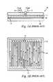
- FIG. 1Aillustrates a prior art heat exchanger 10 which is coupled to an electronic device 99 , such as a microprocessor via a thermal interface material 98 .
- fluidgenerally flows from a single inlet port 12 and flows along the bottom surface 11 in between the parallel microchannels 14 , as shown by the arrows, and exits through the outlet port 16 .
- the heat exchanger 10cools the electronic device 99 , the fluid flows from the inlet port 12 to the outlet port 16 in a uniform manner. In other words, the fluid flows substantially uniformly along the entire bottom surface 11 of the heat exchanger 10 and does not supply more fluid to areas in the bottom surface 11 which correspond with hot spots in the device 99 .
- the temperature of liquid flowing from the inletgenerally increases as it flows along the bottom surface 11 of the heat exchanger. Therefore, regions of the heat source 99 which are downstream or near the outlet port 16 are not supplied with cool fluid, but actually fluid which has already been heated upstream. In effect, the heated fluid actually propagates the heat across the entire bottom surface 11 of the heat exchanger and region of the heat source 99 , whereby fluid near the outlet port 16 is so hot that it becomes ineffective in cooling heat source.
- the heat exchanger 10 having only one inlet 12 and one outlet 16forces fluid to travel along the long parallel microchannels 14 in the bottom surface 11 for the entire length of the heat exchanger 10 , thereby creating a large pressure drop.
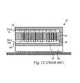
- FIG. 1Billustrates a side view diagram of a prior art multi-level heat exchanger 20 .
- Fluidenters the multi-level heat exchanger 20 through the port 22 and travels downward through multiple jets 28 in the middle layer 26 to the bottom surface 27 and out port 24 .
- the fluid traveling along the jets 28may or may not uniformly flow down to the bottom surface 27 . Nonetheless, although the fluid entering the heat exchanger 20 is spread over the length of the heat exchanger 20 , the design does not provide more fluid to the hotter areas of the heat exchanger 20 and heat source that are in need of more fluid flow circulation.
- conventional heat exchangersare made of materials which have high thermal resistance in the bottom surface, such that the heat exchanger has a coefficient of thermal expansion which matches that of the heat source 99 .
- the high thermal resistance of the heat exchangerthereby does not allow sufficient heat exchange with the heat source 99 .
- larger channel cross-sectional areasare chosen such that more thermal exchange occurs between the heat exchanger 10 and the heat source 99 .
- the dimensions of the channels in the heat exchangerare scaled down and the distance between the channel walls and the hydraulic diameter is made smaller, the thermal resistance of the heat exchanger is reduced.
- a problem with using narrow microchannelsis the increase in pressure drop along the channels. The increase in pressure drop places extreme demands on a pump driving the fluid through the heat exchanger.
- microchannel dimensionsalso cause a larger pressure drop between the inlet and outlet ports, due to the long distance that one or two phase fluid must travel.
- boiling of the fluid in a microchannel heat exchangercauses a larger pressure drop for a given flowrate due to the mixing of fluid and vapor as well as the acceleration of the fluid into the vapor phase. Both of these factors increase the pressure drop per unit length.
- the large pressure drop created within the current microchannel heat exchangersrequire larger pumps which can handle higher pressures and thereby are not feasible in a microchannel setting.
- a microchannel heat exchangerwhich is configured to achieve proper temperature uniformity in the heat source.
- a heat exchangerwhich is configured to achieve proper uniformity in light of hot spots in the heat source.
- a heat exchanger having a relatively high thermal conductivityto adequately perform thermal exchange with the heat source.
- a heat exchangerwhich is configured to achieve a small pressure drop between the inlet and outlet fluid ports.
- a microchannel heat exchangercomprises an interface layer for cooling a heat source.
- the interface layeris configured to pass fluid therethrough and is coupled to the heat source.
- the heat exchangeralso comprises a manifold layer which has a first set fingers and a second set of fingers.
- the first set of fingersprovide fluid to the interface layer at a first set of predetermined locations and the second set of fingers remove fluid from the interface layer at a second set of predetermined locations.
- a particular finger in the first setis spaced apart by an appropriate dimension from a particular finger in the second set to minimize pressure drop in the heat exchanger and configured in an interwoven array.
- the heat exchangerfurther comprises at least one first port in communication with the first set of fingers, wherein fluid enters the heat exchanger through the at least one first port.
- the heat exchangeralso further comprises at least one second port in communication with the second set of fingers, wherein fluid exits the heat exchanger through the at least one second port.
- the manifold layeris positioned above the interface layer, wherein fluid flows downward through the first set of fingers to the interface layer.
- the fingers in the first setare positioned in an alternating configuration with the fingers in the second set. It is preferred that the fingers are parallel and have a constant dimension. Alternatively, the fingers are not parallel and have varying dimensions.
- the heat exchangerfurther comprises a first port passage in communication with the first port and the first set of fingers. The first port passage is configured to channel fluid from the first port to the first set of fingers to minimize pressure drop within the heat exchanger.
- the heat exchangerfurther comprises a second port passage in communication with the second port and the second set of fingers.
- the second port passageis configured to channel fluid from the second set of fingers to the second port to minimize pressure drop within the heat exchanger.
- the heat exchangerfurther comprises an intermediate layer which optimally channels fluid from the manifold layer to the interface layer in at least one predetermined interface hot spot regions.
- the intermediate layeris coupled to the interface layer and the manifold layer and, alternatively, integrally formed with the interface layer and the manifold layer.
- the interface layerhas a thermal conductivity of at least 20 W/m-K and preferably at least 100 W/m-K.
- the interface layerincludes a coating thereupon, wherein the coating provides an appropriate thermal conductivity of at least 20 W/m-K.
- the interface layerfurther comprises a plurality of microchannels configured in a predetermined pattern.
- the plurality of microchannelsare coupled to the interface layer and alternatively integrally formed with the interface layer.
- the interface layerfurther comprises at least one groove that is disposed adjacently to the plurality of microchannels which is aligned with the finger in the first and second sets.
- the thermal conductivity of the coatingis at least 20 W/m-K and alternatively has a coating thereupon, wherein the coating has an appropriate thermal conductivity.
- the interface layeralternatively further comprises a plurality of pillars configured in a predetermined pattern along the interface layer. Alternatively, the interface layer has a roughened surface.
- the interface layeralternatively includes a micro-porous configuration.
- a heat exchanger for cooling a heat sourcecomprises a manifold layer which includes a first set of fingers in a first configuration. Each finger in the first set channels fluid at a first temperature.
- the manifold layerfurther includes a second set of fingers in a second configuration, wherein each finger in the second set channels fluid at a second temperature.
- the first and second sets of fingersare arranged in an interwoven pattern.
- the heat exchangeralso comprises an interface layer that is coupled to the heat source and is configured to receive fluid at the first temperature at a plurality of first locations. Each first location is associated with a corresponding finger in the first set, whereby the interface layer passes fluid along a plurality of predetermined paths to a plurality of second locations.
- Each second locationis associated with a corresponding finger in the second set.
- a particular finger in the first setis spaced apart by an appropriate dimension from a particular finger in the second set, wherein the appropriate dimension provides a minimal pressure drop in the heat exchanger. It is preferred that the fingers are parallel and have a constant dimension. Alternatively, the fingers are not parallel and have varying dimensions.
- the heat exchangerfurther comprises at least one first port that is in communication with the first set of fingers, whereby fluid enters the heat exchanger through the at least one first port.
- the heat exchangerfurther comprises at least one second port in communication with the second set of fingers, whereby fluid exits the heat exchanger through the at least one second port.
- the manifold layeris preferably positioned above the interface layer, wherein fluid flows downward through the first set of fingers to the interface layer.
- the fingers in the first setare positioned in an alternating configuration with the fingers in the second set.
- the heat exchangerfurther comprises a first port passage that is in communication with the first port and the first set of fingers.
- the first port passageis configured to channel fluid from the first port to the first set of fingers to minimize pressure drop within the heat exchanger.
- the heat exchangerfurther comprises a second port passage that is in communication with the second port and the second set of fingers.
- the second port passageis configured to channel fluid from the second set of fingers to the second port to minimize pressure drop within the heat exchanger.
- the heat exchangerfurther comprises an intermediate layer which optimally channels fluid from the manifold layer to the interface layer at least one predetermined interface hot spot regions.
- the intermediate layeris positioned between the interface layer and the manifold layer, wherein the intermediate layer optimally channels fluid to at least one predetermined interface hot spot regions in the interface layer.
- the intermediate layeris coupled to the interface layer and the manifold layer and, alternatively, is integrally formed with the interface layer and the manifold layer.
- the interface layerhas a thermal conductivity of at least 20 W/m-K and alternatively includes a coating thereupon, wherein the coating provides an appropriate thermal conductivity of at least 20 W/m-K and preferably at least 100 W/m-K.
- the interface layerfurther comprises a plurality of microchannels configured in a predetermined pattern.
- the plurality of microchannelsare coupled to the interface layer and, alternatively, integrally formed with the interface layer.
- the interface layerfurther comprises at least one groove that is disposed adjacently to the plurality of microchannels which is aligned with the finger in the first set.
- the thermal conductivity of the coatingis at least 20 W/m-K and alternatively has a coating thereupon, wherein the coating has an appropriate thermal conductivity.
- the interface layeralternatively further comprises a plurality of pillars configured in a predetermined pattern along the interface layer. Alternatively, the interface layer has a roughened surface.
- the interface layeralternatively includes a micro-porous configuration.
- a microchannel heat exchangeris coupled to a heat source and configured to cool the heat source.
- the microchannel heat exchangercomprises a first set of fingers which provide fluid at a first temperature to a heat exchange region.
- the fluid in the heat exchange regionflows toward a second set of fingers and exits the heat exchanger at a second temperature.
- Each fingeris spaced apart from an adjacent finger by an appropriate dimension to minimize pressure drop in the heat exchanger and arranged in an interwoven or inter-digitated pattern.
- the microchannel heat exchangerfurther comprises an interface layer which has a heat exchange region, wherein the fluid undergoes thermal exchange with the heat source along the heat exchange region.
- the interface layerfurther comprises the first set of fingers and the second set of fingers which are configured along the heat exchange region.
- the microchannel heat exchangerfurther comprises a manifold layer for providing fluid to the interface layer, wherein the manifold layer includes the first set of fingers and the second set of fingers configured within.
- the heat exchangerfurther comprises at least one first port that is in communication with the first set of fingers, whereby fluid enters the heat exchanger through the at least one first port.
- the heat exchangerfurther comprises at least one second port in communication with the second set of fingers, whereby fluid exits the heat exchanger through the at least one second port.
- the manifold layeris preferably positioned above the interface layer, wherein fluid flows downward through the first set of fingers to the interface layer.
- the fingers in the first setare positioned in an alternating configuration with the fingers in the second set.
- the heat exchangerfurther comprises a first port passage that is in communication with the first port and the first set of fingers.
- the first port passageis configured to channel fluid from the first port to the first set of fingers to minimize pressure drop within the heat exchanger.
- the heat exchangerfurther comprises a second port passage that is in communication with the second port and the second set of fingers.
- the second port passageis configured to channel fluid from the second set of fingers to the second port to minimize pressure drop within the heat exchanger.
- the heat exchangerfurther comprises an intermediate layer which optimally channels fluid from the manifold layer to the interface layer at least one predetermined interface hot spot regions.
- the intermediate layeris positioned between the interface layer and the manifold layer, wherein the intermediate layer optimally channels fluid to at least one predetermined interface hot spot regions in the interface layer.
- the intermediate layeris coupled to the interface layer and the manifold layer and, alternatively, is integrally formed with the interface layer and the manifold layer.
- the interface layerhas a thermal conductivity of at least 20 W/m-K and alternatively includes a coating thereupon, wherein the coating provides an appropriate thermal conductivity of at least 20 W/m-K.
- the interface layerfurther comprises a plurality of microchannels configured in a predetermined pattern. The plurality of microchannels are coupled to the interface layer and, alternatively, integrally formed with the interface layer.
- the interface layerfurther comprises at least one groove that is disposed adjacently to the plurality of microchannels which is aligned with the finger in the first set.
- the thermal conductivity of the coatingis at least 20 W/m-K and alternatively has a coating thereupon, wherein the coating has an appropriate thermal conductivity.
- the interface layeralternatively further comprises a plurality of pillars configured in a predetermined pattern along the interface layer. Alternatively, the interface layer has a roughened surface.
- the interface layeralternatively includes a micro-porous configuration.
- a method of cooling a heat sourcecomprises providing fluid at a first temperature to a heat exchange region via a first set of fingers in a first configuration.
- the methodalso comprises channeling the fluid along a plurality of predetermined paths along the heat exchange region, wherein the fluid is channeled to a second set of fingers in a second configuration.
- the fingers in each setare configured to minimize pressure drop and in an inter-digitated or interwoven array.
- the methodalso comprises removing fluid at a second temperature from the heat exchange region via the second set of fingers.
- the first set and second set of fingersare disposed above the heat exchange region.
- the first set and second set of fingersare disposed along the heat exchange region.
- FIG. 1Aillustrates a side view of a conventional heat exchanger.
- FIG. 1Billustrates a top view of the conventional heat exchanger.
- FIG. 1Cillustrates a side view diagram of a prior art multi-level heat exchanger.
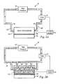
- FIG. 2Aillustrates a schematic diagram of a closed loop cooling system incorporating a preferred embodiment of the flexible fluid delivery microchannel heat exchanger of the present invention.
- FIG. 2Billustrates a schematic diagram of a closed loop cooling system incorporating an alternative embodiment of the flexible fluid delivery microchannel heat exchanger of the present invention.
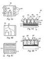
- FIG. 3Aillustrates a top view of an alternative manifold layer of the heat exchanger in accordance with the present invention.
- FIG. 3Billustrates an exploded view of an alternative heat exchanger with the alternative manifold layer in accordance with the present invention.
- FIG. 4illustrates a perspective view of the preferred interwoven manifold layer in accordance with the present invention.
- FIG. 5illustrates a top view of the preferred interwoven manifold layer with interface layer in accordance with the present invention.
- FIG. 6Aillustrates a cross-sectional view of the preferred interwoven manifold layer with interface layer of the present invention along lines A—A.
- FIG. 6Billustrates a cross-sectional view of the preferred interwoven manifold layer with interface layer of the present invention along lines B—B.
- FIG. 6Cillustrates a cross-sectional view of the preferred interwoven manifold layer with interface layer of the present invention along lines C—C.
- FIG. 7Aillustrates an exploded view of the preferred interwoven manifold layer with interface layer of the present invention.
- FIG. 7Billustrates a perspective view of an alternative embodiment of the interface layer of the present invention.
- FIG. 8Aillustrates a top view diagram of an alternate manifold layer in accordance with the present invention.
- FIG. 8Billustrates a top view diagram of the interface layer in accordance with the present invention.
- FIG. 8Cillustrates a top view diagram of the interface layer in accordance with the present invention.
- FIG. 9Aillustrates a side view diagram of the alternative embodiment of the three tier heat exchanger in accordance with the present invention.
- FIG. 9Billustrates a side view diagram of the alternative embodiment of the two tier heat exchanger in accordance with the present invention.
- FIG. 10illustrates a perspective view of the interface layer having a micro-pin array in accordance with the present invention.
- FIG. 11illustrates a cut-away perspective view diagram of the alternate heat exchanger in accordance with the present invention.
- FIG. 12illustrates a side view diagram of the interface layer of the heat exchanger having a coating material applied thereon in accordance with the present invention.
- FIG. 13illustrates a flow chart of an alternative method of manufacturing the heat exchanger in accordance with the present invention.
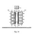
- FIG. 14illustrates a schematic of an alternate embodiment of the present invention having two heat exchangers coupled to a heat source.
- the heat exchangercaptures thermal energy generated from a heat source by passing fluid through selective areas of the interface layer which is preferably coupled to the heat source.
- the fluidis directed to specific areas in the interface layer to cool the hot spots and areas around the hot spots to generally create temperature uniformity across the heat source while maintaining a small pressure drop within the heat exchanger.
- the heat exchangerutilizes a plurality of apertures, channels and/or fingers in the manifold layer as well as conduits in the intermediate layer to direct and circulate fluid to and from selected hot spot areas in the interface layer.
- the heat exchangerincludes several ports which are specifically disposed in predetermined locations to directly deliver fluid to and remove fluid from the hot spots to effectively cool the heat source.
- microchannel heat exchanger of the present inventionis described and discussed in relation to flexible fluid delivery for cooling hot spot locations in a device, the heat exchanger is alternatively used for flexible fluid delivery for heating a cold spot location in a device. It should also be noted that although the present invention is preferably described as a microchannel heat exchanger, the present invention can be used in other applications and is not limited to the discussion herein.
- FIG. 2Aillustrates a schematic diagram of a closed loop cooling system 30 which includes a preferred flexible fluid delivery microchannel heat exchanger 400 in accordance with the present invention.
- FIG. 2Billustrates a schematic diagram of a closed loop cooling system 30 which includes an alternative flexible fluid delivery microchannel heat exchanger 200 with multiple ports 108 , 109 in accordance with the present invention.
- the fluid ports 108 , 109are coupled to fluid lines 38 which are coupled to a pump 32 and heat condensor 30 .
- the pump 32pumps and circulates fluid within the closed loop 30 .
- one fluid port 108is used to supply fluid to the heat exchanger 100 .
- one fluid port 109is used to remove fluid from the heat exchanger 100 .
- Preferably a uniform, constant amount of fluid flowenters and exits the heat exchanger 100 via the respective fluid ports 108 , 109 .
- different amounts of fluid flowenter and exit through the inlet and outlet port(s) 108 , 109 at a given time.
- one pumpprovides fluid to several designated inlet ports 108 .
- multiple pumps(not shown), provide fluid to their respective inlet and outlet ports 108 , 109 .
- the dynamic sensing and control module 34is alternatively employed in the system to variate and dynamically control the amount and flow rate of fluid entering and exiting the preferred or alternative heat exchanger in response to varying hot spots or changes in the amount of heat in a hot spot location as well as the locations of the hot spots.
- the preferred embodimentis a three level heat exchanger 400 which includes an interface layer 402 , at least one intermediate layer 404 and at least one manifold layer 406 .
- the preferred manifold layer 402 and the preferred interface layer 402are shown in FIG. 7 and the intermediate layer 104 is shown in FIG. 3 B.
- the heat exchanger 400is a two level apparatus which includes the interface layer 402 and the manifold layer 406 , as shown in FIG. 7 . As shown in FIGS.
- the heat exchanger 400is coupled to a heat source 99 , such as an electronic device, including, but not limited to a microchip and integrated circuit, whereby a thermal interface material 98 is preferably disposed between the heat source 99 and the heat exchanger 100 .
- a thermal interface material 98is preferably disposed between the heat source 99 and the heat exchanger 100 .
- the heat exchanger 400is directly coupled to the surface of the heat source 99 .
- the heat exchanger 400is alternatively integrally formed into the heat source 99 , whereby the heat exchanger 400 and the heat source 99 are formed as one piece.
- the interface layer 102is integrally disposed with the heat source 99 and is formed as one piece with the heat source.
- the heat exchanger 400 of the present inventionis configured to be directly or indirectly in contact with the heat source 99 which is rectangular in shape, as shown in the figures.
- the heat exchanger 400can have any other shape conforming with the shape of the heat source 99 .
- the heat exchanger of the present inventioncan be configured to have an outer semicircular shape which allows the heat exchanger (not shown) to be in direct or indirect contact with a corresponding semicircular shaped heat source (not shown).
- the heat exchanger 400is slightly larger in dimension than the heat source within the range of and including 0.5-5.0 millimeters.
- FIG. 3Aillustrates a top view of the alternate manifold layer 106 of the present invention.
- the manifold layer 106includes four sides as well as a top surface 130 and a bottom surface 132 .
- the top surface 130is removed in FIG. 3A to adequately illustrate and describe the workings of the manifold layer 106 .
- the manifold layer 106has a series of channels or passages 116 , 118 , 120 , 122 as well as ports 108 , 109 formed therein.
- the fingers 118 , 120extend completely through the body of the manifold layer 106 in the Z-direction as shown in FIG. 3 B.
- the fingers 118 and 120extend partially through the manifold layer 106 in the Z-direction and have apertures as shown in FIG. 3 A.
- passages 116 and 122extend partially through the manifold layer 106 .
- the remaining areas between the inlet and outlet passages 116 , 120designated as 107 , extend from the top surface 130 to the bottom surface 132 and form the body of the manifold layer 106 .
- the fluidenters manifold layer 106 via the inlet port 108 and flows along the inlet channel 116 to several fingers 118 which branch out from the channel 116 in several directions in the X and/or Y directions to apply fluid to selected regions in the interface layer 102 .
- the fingers 118are arranged in different predetermined directions to deliver fluid to the locations in the interface layer 102 corresponding to the areas at or near the hot spots in the heat source. These locations in the interface layer 102 are hereinafter referred to as interface hot spot regions.
- the fingersare configured to cool stationary as well as temporally varying interface hot spot regions. As shown in FIG.
- the channels 116 , 122 and fingers 118 , 120are disposed in the X and/or Y directions in the manifold layer 106 .
- the various directions of the channels 116 , 122 and fingers 118 , 120allow delivery of fluid to cool hot spots in the heat source 99 and/or minimize pressure drop within the heat exchanger 100 .
- channels 116 , 122 and fingers 118 , 120are periodically disposed in the manifold layer 106 and exhibit a pattern, as in the preferred embodiment.
- the arrangement as well as the dimensions of the fingers 118 , 120are determined in light of the hot spots in the heat source 99 that are desired to be cooled.
- the locations of the hot spots as well as the amount of heat produced near or at each hot spotare used to configure the manifold layer 106 such that the fingers 118 , 120 are placed above or proximal to the interface hot spot regions in the interface layer 102 .
- the manifold layer 106preferably allows one phase and/or two-phase fluid to circulate to the interface layer 102 without allowing a substantial pressure drop from occurring within the heat exchanger 100 and the system 30 (FIG. 2 A).
- the fluid delivery to the interface hot spot regionscreates a uniform temperature at the interface hot spot region as well as areas in the heat source adjacent to the interface hot spot regions.
- the dimensions as well as the number of channels 116 and fingers 118depend on a number of factors.
- the inlet and outlet fingers 118 , 120have the same width dimensions.
- the inlet and outlet fingers 118 , 120have different width dimensions.
- the width dimensions of the fingers 118 , 120are preferably within the range of and including 0.25-0.50 millimeters.
- the inlet and outlet fingers 118 , 120have the same length and depth dimensions.
- the inlet and outlet fingers 118 , 120have different length and depth dimensions.
- the inlet and outlet fingers 118 , 120have varying width dimensions along the length of the fingers.
- the length dimensions of the inlet and outlet fingers 118 , 120are within the range of and including 0.5 millimeters to three times the size of the heat source length.
- the fingers 118 , 120have a height or depth dimension within the range and including 0.25-0.50 millimeters.
- less than 10 or more than 30 fingers per centimeterare disposed in the manifold layer 106 .
- the geometries of the fingers 118 , 120 and channels 116 , 122are in non-periodic arrangement to aid in optimizing hot spot cooling of the heat source.
- the spatial distribution of the heat transfer to the fluidis matched with the spatial distribution of the heat generation.
- the fluidflows along the interface layer through the microchannels 110 , its temperature increases and as it begins to transform to vapor under two-phase conditions.
- the fluidundergoes a significant expansion which results in a large increase in velocity.
- the efficiency of the heat transfer from the interface layer to the fluidis improved for high velocity flow. Therefore, it is possible to tailor the efficiency of the heat transfer to the fluid by adjusting the cross-sectional dimensions of the fluid delivery and removal fingers 118 , 120 and channels 116 , 122 in the heat exchanger 100 .
- a particular fingercan be designed for a heat source where there is higher heat generation near the inlet.
- a fingercan be designed to start out with a small cross sectional area at the inlet to cause high velocity flow of fluid.
- the particular finger or channelcan also be configured to expand to a larger cross-section at a downstream outlet to cause a lower velocity flow. This design of the finger or channel allows the heat exchanger to minimize pressure drop and optimize hot spot cooling in areas where the fluid increases in volume, acceleration and velocity due to transformation from liquid to vapor in two-phase flow.
- the fingers 118 , 120 and channels 116 , 122can be designed to widen and then narrow again along their length to increase the velocity of the fluid at different places in the microchannel heat exchanger 100 .
- the manifold layer 106includes one or more apertures 119 in the inlet fingers 118 .
- the fluid flowing along the fingers 118flows down the apertures 119 to the intermediate layer 104 .
- the fluid flowing along the fingers 118flows down the apertures 119 directly to the interface layer 102 .
- the manifold layer 106includes apertures 121 in the outlet fingers 120 .
- the fluid flowing from the intermediate layer 104flows up the apertures 121 into the outlet fingers 120 .
- the fluid flowing from the interface layer 102flows directly up the apertures 121 into the outlet fingers 120 .
- the inlet and outlet fingers 118 , 120are open channels which do not have apertures.
- the bottom surface 103 of the manifold layer 106abuts against the top surface of the intermediate layer 104 in the three tier exchanger 100 or abuts against the interface layer 102 in the two tier exchanger.
- fluidflows freely to and from the intermediate layer 104 and the manifold layer 106 .
- the fluidis directed to and from the appropriate interface hot spot region by conduits 105 in the intermediate layer 104 . It is apparent to one skilled in the art that the conduits 105 are directly aligned with the fingers, as described below or positioned elsewhere in the three tier system.
- FIG. 3Billustrates an exploded view of the three tier heat exchanger 100 with the alternate manifold layer in accordance with the present invention.
- the heat exchanger 100is a two layer structure which includes the manifold layer 106 and the interface layer 102 , whereby fluid passes directly between the manifold layer 106 and interface layer 102 without passing through the intermediate layer 104 . It is apparent to one skilled in the art that the configuration of the manifold, intermediate and interface layers are shown for exemplary purposes and is thereby not limited to the configuration shown.
- the intermediate layer 104includes a plurality of conduits 105 which extend therethrough.
- the inflow conduits 105direct fluid entering from the manifold layer 106 to the designated interface hot spot regions in the interface layer 102 .
- the apertures 105also channel fluid flow from the interface layer 102 to the exit fluid port(s) 109 .
- the intermediate layer 104also provides fluid delivery from the interface layer 102 to the exit fluid port 109 where the exit fluid port 108 is in communication with the manifold layer 106 .
- the conduits 105are positioned in the interface layer 104 in a predetermined pattern based on a number of factors including, but not limited to, the locations of the interface hot spot regions, the amount of fluid flow needed in the interface hot spot region to adequately cool the heat source 99 and the temperature of the fluid.
- the conduitshave a width dimension of 100 microns, although other width dimensions are contemplated up to several millimeters.
- the conduits 105have other dimensions dependent on at least the above mentioned factors. It is apparent to one skilled in the art that each conduit 105 in the intermediate layer 104 has a same shape and/or dimension, although it is not necessary. For instance, like the fingers described above, the conduits alternatively have a varying length and/or width dimension.
- the conduits 105may have a constant depth or height dimension through the intermediate layer 104 .
- the conduits 105have a varying depth dimension, such as a trapezoidal or a nozzle-shape, through the intermediate layer 104 .
- the horizontal shape of the conduits 105are shown to be rectangular in FIG. 2C , the conduits 105 alternatively have any other shape including, but not limited to, circular (FIG. 3 A), curved and elliptical.
- one or more of the conduits 105are shaped and contour with a portion of or all of the finger or fingers above.
- the intermediate layer 104is horizontally positioned within the heat exchanger 100 with the conduits 105 positioned vertically. Alternatively, the intermediate layer 104 is positioned in any other direction within the heat exchanger 100 including, but not limited to, diagonal and curved forms. Alternatively, the conduits 105 are positioned within the intermediate layer 104 in a horizontally, diagonally, curved or any other direction. In addition, the intermediate layer 104 extends horizontally along the entire length of the heat exchanger 100 , whereby the intermediate layer 104 completely separates the interface layer 102 from the manifold layer 106 to force the fluid to be channeled through the conduits 105 .
- a portion of the heat exchanger 100does not include the intermediate layer 104 between the manifold layer 106 and the interface layer 102 , whereby fluid is free to flow therebetween.
- the intermediate layer 104alternatively extends vertically between the manifold layer 106 and the interface layer 102 to form separate, distinct intermediate layer regions.
- the intermediate layer 104does not fully extend from the manifold layer 106 to interface layer 102 .
- FIG. 3Billustrates a perspective view of the interface layer 102 in accordance with the present invention.
- the interface layer 102includes a bottom surface 103 and a plurality of microchannel walls 110 , whereby the area in between the microchannel walls 110 channels or directs fluid along a fluid flow path.
- the bottom surface 103is flat and has a high thermal conductivity to allow sufficient heat transfer from the heat source 99 .
- the bottom surface 103includes troughs and/or crests designed to collect or repel fluid from a particular location.
- the microchannel walls 110are configured in a parallel configuration, as shown in FIG. 3B , whereby fluid preferably flows between the microchannel walls 110 along a fluid path.
- the microchannel walls 110have non-parallel configurations.
- microchannel walls 110are alternatively configured in any other appropriate configuration depending on the factors discussed above.
- the interface layer 102alternatively has grooves in between sections of microchannel walls 110 , as shown in FIG. 8 C.
- the microchannel walls 110have dimensions which minimize the pressure drop or differential within the interface layer 102 .
- any other features, besides microchannel walls 110are also contemplated, including, but not limited to, pillars (FIG. 10 ), roughed surfaces, and a micro-porous structure, such as sintered metal and silicon foam (FIG. 10 ).
- the parallel microchannel walls 110 shown in FIG. 3Bis used to describe the interface layer 102 in the present invention.
- the microchannel walls 110allow the fluid to undergo thermal exchange along the selected hot spot locations of the interface hot spot region to cool the heat source 99 in that location.
- the microchannel walls 110have a width dimension within the range of 20-300 microns and a height dimension within the range of 100 microns to one millimeter, depending on the power of the heat source 99 .
- the microchannel walls 110have a length dimension which ranges between 100 microns and several centimeters, depending on the dimensions of the heat source, as well as the size of the hot spots and the heat flux density from the heat source. Alternatively, any other microchannel wall dimensions are contemplated.
- the microchannel walls 110are spaced apart by a separation dimension range of 50-500 microns, depending on the power of the heat source 99 , although any other separation dimension range is contemplated.
- the top surface of the manifold layer 106is cut away to illustrate the channels 116 , 122 and fingers 118 , 120 within the body of the manifold layer 106 .
- the locations in the heat source 99 that produce more heatare hereby designated as hot spots, whereby the locations in the heat source 99 which produce less heat are hereby designated as warm spots.
- the heat source 99is shown to have a hot spot region, namely at location A, and a warm spot region, namely at location B.
- the areas of the interface layer 102 which abut the hot and warm spotsare accordingly designated interface hot spot regions.
- the interface layer 102includes interface hot spot region A, which is positioned above location A and interface hot spot region B, which is positioned above location B.
- fluidinitially enters the heat exchanger 100 through one inlet port 108 .
- the fluidthen preferably flows to one inlet channel 116 .
- the heat exchanger 100includes more than one inlet channel 116 .
- fluid flowing along the inlet channel 116 from the inlet port 108initially branches out to finger 118 D.
- the fluid which continues along the rest of the inlet channel 116flows to individual fingers 118 B and 118 C and so on.
- fluidis supplied to interface hot spot region A by flowing to the finger 118 A, whereby fluid flows down through finger 118 A to the intermediate layer 104 .
- the fluidthen flows through the inlet conduit 105 A positioned below the finger 118 A to the interface layer 102 , whereby the fluid undergoes thermal exchange with the heat source 99 .
- the fluidtravels along the microchannels 110 as shown in FIG. 3B , although the fluid may travel in any other direction along the interface layer 102 .
- the heated liquidthen travels upward through the conduit 105 B to the outlet finger 120 A.
- fluidflows down in the Z-direction through fingers 118 E and 118 F to the intermediate layer 104 .
- the fluidthen flows through the inlet conduit 105 C down in the Z-direction to the interface layer 102 .
- the heated fluidthen travels upward in the Z-direction from the interface layer 102 through the outlet conduit 105 D to the outlet fingers 120 E and 120 F.
- the heat exchanger 100removes the heated fluid in the manifold layer 106 via the outlet fingers 120 , whereby the outlet fingers 120 are in communication with the outlet channel 122 .
- the outlet channel 122allows fluid to flow out of the heat exchanger through one outlet port 109 .
- the inflow and outflow conduits 105are positioned directly or nearly directly above the appropriate interface hot spot regions to directly apply fluid to hot spots in the heat source 99 .
- each outlet finger 120is configured to be positioned closest to a respective inlet finger 119 for a particular interface hot spot region to minimize pressure drop therebetween.
- fluidenters the interface layer 102 via the inlet finger 118 A and travels the least amount of distance along the bottom surface 103 of the interface layer 102 before it exits the interface layer 102 to the outlet finger 120 A. It is apparent that the amount of distance which the fluid travels along the bottom surface 103 adequately removes heat generated from the heat source 99 without generating an unnecessary amount of pressure drop.
- the corners in the fingers 118 , 120are curved to reduce pressure drop of the fluid flowing along the fingers 118 .
- the configuration of the manifold layer 106 shown in FIGS. 3A and 3Bis only for exemplary purposes.
- the configuration of the channels 116 and fingers 118 in the manifold layer 106depend on a number of factors, including but not limited to, the locations of the interface hot spot regions, amount of flow to and from the interface hot spot regions as well as the amount of heat produced by the heat source in the interface hot spot regions.
- the preferred configuration of the manifold layer 106includes an interdigitated pattern of parallel inlet and outlet fingers that are arranged along the width of the manifold layer, as shown in FIGS. 4-7A and discussed below. Nonetheless, any other configuration of channels 116 and fingers 118 is contemplated.
- FIG. 4illustrates a perspective view of the preferred manifold layer 406 in accordance with the heat exchanger of the present invention.
- the manifold layer 406 in FIG. 4preferably includes a plurality of interwoven or inter-digitated parallel fluid fingers 411 , 412 which allow one phase and/or two-phase fluid to circulate to the interface layer 402 without allowing a substantial pressure drop from occurring within the heat exchanger 400 and the system 30 (FIG. 2 A).
- the inlet fingers 411are arranged alternately with the outlet fingers 412 .
- the fingersare alternatively designed such that a parallel finger branches off from or is linked to another parallel finger.
- the inlet fingers or passages 411supply the fluid entering the heat exchanger to the interface layer 402
- the outlet fingers or passages 412remove the fluid from the interface layer 402 which then exits the heat exchanger 400 .
- the preferred configuration of the manifold layer 406allows the fluid to enter the interface layer 402 and travel a very short distance in the interface layer 402 before it enters the outlet passage 412 .
- the substantial decrease in the length that the fluid travels along the interface layer 402substantially decreases the pressure drop in the heat exchanger 400 and the system 30 (FIG. 2 A).
- the preferred manifold layer 406includes a passage 414 which is in communication with two inlet passages 411 and provides fluid thereto. As shown in FIGS. 8-9 the manifold layer 406 includes three outlet passages 412 which are in communication with passage 418 .
- the passages 414 in the manifold layer 406have a flat bottom surface which channels the fluid to the fingers 411 , 412 .
- the passage 414has a slight slope which aids in channeling the fluid to selected fluid passages 411 .
- the inlet passage 414includes one or more apertures in its bottom surface which allows a portion of the fluid to flow down to the interface layer 402 .
- the passage 418 in the manifold layerhas a flat bottom surface which contains the fluid and channels the fluid to the port 408 .
- the passage 418has a slight slope which aids in channeling the fluid to selected outlet ports 408 .
- the passages 414 , 418have a dimension width of approximately 2 millimeters, although any other width dimensions are alternatively contemplated.
- the passages 414 , 418are in communication with ports 408 , 409 whereby the ports are coupled to the fluid lines 38 in the system 30 (FIG. 2 A).
- the manifold layer 406preferably includes horizontally configured fluid ports 408 , 409 .
- the manifold layer 406includes vertically and/or diagonally configured fluid ports 408 , 409 , as discussed below, although not shown in FIG. 4-7 .
- the manifold layer 406does not include passage 414 .
- fluidis directly supplied to the fingers 411 from the ports 408 .
- the manifold layer 411alternatively does not include passage 418 , whereby fluid in the fingers 412 directly flows out of the heat exchanger 400 through ports 408 . It is apparent that although two ports 408 are shown in communication with the passages 414 , 418 , any other number of ports are alternatively utilized.
- the inlet passages 411preferably have dimensions which allow fluid to travel to the interface layer without generating a large pressure drop along the passages 411 and the system 30 (FIG. 2 A).
- the inlet passages 411preferably have a width dimension in the range of and including 0.25-5.00 millimeters, although any other width dimensions are alternatively contemplated.
- the inlet passages 411preferably have a length dimension in the range of and including 0.5 millimeters to three times the length of the heat source. Alternatively, other length dimensions are contemplated.
- the inlet passages 411extend down to or slightly above the height of the microchannels 410 such that the fluid is channeled directly to the microchannels 410 .
- the inlet passages 411preferably have a height dimension in the range of and including 0.25-5.00 millimeters. It is apparent to one skilled in the art that the passages 411 do not extend down to the microchannels 410 and that any other height dimensions are alternatively contemplated. It is apparent to one skilled in the art that although the inlet passages 411 have the same dimensions, it is contemplated that the inlet passages 411 alternatively have different dimensions. In addition, the inlet passages 411 alternatively have varying widths, cross sectional dimensions and/or distances between adjacent fingers, varying dimensions. In particular, the passage 411 has areas with a larger width or depths as well as areas with narrower widths and depths along its length. The varied dimensions allow more fluid to be delivered to predetermined interface hot spot regions in the interface layer 402 through wider portions while restricting flow to warm spot interface hot spot regions through the narrow portions.
- the outlet passages 412preferably have dimensions which allow fluid to travel to the interface layer without generating a large pressure drop along the passages 412 as well as the system 30 (FIG. 2 A).
- the outlet passages 412preferably have a width dimension in the range of and including 0.25-5.00 millimeters, although any other width dimensions are alternatively contemplated.
- the outlet passages 412preferably have a length dimension in the range of and including 0.5 millimeters to three times the length of the heat source.
- the outlet passages 412extend down to the height of the microchannels 410 such that the fluid easily flows upward in the outlet passages 412 after horizontally flowing along the microchannels 410 .
- the inlet passages 411preferably have a height dimension in the range of and including 0.25-5.00 millimeters, although any other height dimensions are alternatively contemplated. It is apparent to one skilled in the art that although outlet passages 412 have the same dimensions, it is contemplated that the outlet passages 412 alternatively have different dimensions. Again, the inlet passage 412 alternatively have varying widths, cross sectional dimensions and/or distances between adjacent fingers.
- the inlet and outlet passages 411 , 412are preferably segmented and distinct from one another, as shown in FIGS. 4 and 5 , whereby fluid among the passages do not mix together.
- two outlet passagesare located along the outside edges of the manifold layer 406
- one outlet passage 412is located in the middle of the manifold layer 406 .
- two inlet passages 411are configured on adjacent sides of the middle outlet passage 412 . This particular configuration causes fluid entering the interface layer 402 to travel the a short distance in the interface layer 402 before it flows out of the interface layer 402 through the outlet passage 412 .
- inlet passages and outlet passagesmay be positioned in any other appropriate configuration and is thereby not limited to the configuration shown and described in the present disclosure.
- the number of inlet and outlet fingers 411 , 412are more than three within the manifold layer 406 but less than 10 per centimeter across the manifold layer 406 . It is also apparent to one skilled in the art that any other number of inlet passages and outlet passages may be used and thereby is not limited to the number shown and described in the present disclosure.
- the manifold layer 406is coupled to the intermediate layer (not shown), whereby the intermediate layer (not shown) is coupled to the interface layer 402 to form a three-tier heat exchanger 400 .
- the intermediate layer discussed hereinis referred to above in the embodiment shown in FIG. 3 B.
- the manifold layer 406is alternatively coupled to the interface layer 402 and positioned above the interface layer 402 to form a two-tier heat exchanger 400 , as shown in FIG. 7 A.
- FIGS. 6A-6Cillustrate cross-sectional schematics of the preferred manifold layer 406 coupled to the interface layer 402 in the two tier heat exchanger. Specifically, FIG. 6A illustrates the cross section of the heat exchanger 400 along line A—A in FIG. 5 . In addition, FIG.
- FIG. 6Billustrates the cross section of the heat exchanger 400 along line B—B
- FIG. 6Cillustrates the cross section of the heat exchanger 400 along line C—C in FIG. 5
- the inlet and outlet passages 411 , 412extend from the top surface to the bottom surface of the manifold layer 406 .
- the inlet and outlet passages 411 , 412are at or slightly above the height of the microchannels 410 in the interface layer 402 .
- This configurationcauses the fluid from the inlet passages 411 to easily flow from the passages 411 through the microchannels 410 .
- this configurationcauses fluid flowing through the microchannels to easily flow upward through the outlet passages 412 after flowing through the microchannels 410 .
- the intermediate layer 104( FIG. 3B ) is positioned between the manifold layer 406 and the interface layer 402 , although not shown in the figures.
- the intermediate layer 104( FIG. 3B ) channels fluid flow to designated interface hot spot regions in the interface layer 402 .
- the intermediate layer 104( FIG. 3B ) is preferably utilized to provide a uniform flow of fluid entering the interface layer 402 .
- the intermediate layer 104is preferably utilized to provide fluid to the interface hot spot regions in the interface layer 402 to adequately cool hot spots and create temperature uniformity in the heat source 99 .
- the inlet and outlet passages 411 , 412are preferably positioned near or above hot spots in the heat source 99 to adequately cool the hot spots, although it is not necessary.
- FIG. 7Aillustrates an exploded view of the alternate manifold layer 406 with the an alternative interface layer 102 of the present invention.
- the interface layer 102includes continuous arrangements of microchannel walls 110 , as shown in FIG. 3 B.
- fluidenters the manifold layer 406 at fluid port 408 and travels through the passage 414 and towards the fluid fingers or passages 411 .
- the fluidenters the opening of the inlet fingers 411 and preferably flows the length of the fingers 411 in the X-direction, as shown by the arrows.
- the fluidflows downward in the Z-direction to the interface layer 402 which is positioned below the manifold layer 406 .
- the fluid in the interface layer 402traverses along the bottom surface in the X and Y directions of the interface layer 402 and performs thermal exchange with the heat source 99 .
- the heated fluidexits the interface layer 402 by preferably flowing upward in the Z-direction via the outlet fingers 412 , whereby the outlet fingers 412 channel the heated fluid to the passage 418 in the manifold layer 406 in the X-direction.
- the fluidthen flows along the passage 418 and exits the heat exchanger by flowing out through the port 409 .
- the interface layerincludes a series of grooves 416 disposed in between sets of microchannels 410 which aid in channeling fluid to and from the passages 411 , 412 .
- the grooves 416 Aare located directly beneath the inlet passages 411 of the alternate manifold layer 406 , whereby fluid entering the interface layer 402 via the inlet passages 411 is directly channeled to the microchannels adjacent to the groove 416 A.
- the grooves 416 Aallow fluid to be directly channeled into specific designated flow paths from the inlet passages 411 , as shown in FIG. 5 .
- the interface layer 402includes grooves 416 B which are located directly beneath the outlet passages 412 in the Z-direction.
- fluid flowing horizontally along the microchannels 410 toward the outlet passagesare channeled horizontally to the grooves 416 B and vertically to the outlet passage 412 above the grooves 416 B.
- FIG. 6Aillustrates the cross section of the heat exchanger 400 with the manifold layer 406 and the interface layer 402 .
- FIG. 6Ashows the inlet passages 411 interwoven with the outlet passages 412 , whereby fluid flows down the inlet passages 411 and up the outlet passages 412 .
- the fluidflows horizontally through the microchannel walls 410 which are disposed between the inlet passages and outlet passages and separated by the microchannels 410 .
- the microchannel wallsare continuous ( FIG. 3B ) and are not separated by the grooves. As shown in FIG.
- either or both of the inlet and outlet passages 411 , 412preferably have a curved surface 420 at their ends at the location near the grooves 416 .
- the curved surface 420directs fluid flowing down the passage 411 towards the microchannels 410 which are located adjacent to the passage 411 .
- fluid entering the interface layer 102is more easily directed toward the microchannels 410 instead of flowing directly to the groove 416 A.
- the curved surface 420 in the outlet passages 412assists in directing fluid from the microchannels 410 to the outer passage 412 .
- the interface layer 402 ′includes the inlet passages 411 ′ and outlet passages 412 ′ discussed above with respect to the manifold layer 406 (FIGS. 8 - 9 ).
- the fluidis supplied directly to the interface layer 402 ′ from the port 408 ′.
- the fluidflows along the passage 414 ′ towards the inlet passages 411 ′.
- the fluidthen traverses laterally along the sets of microchannels 410 ′ and undergoes heat exchange with the heat source (not shown) and flows to the outlet passages 412 ′.
- the fluidthen flows along the outlet passages 412 ′ to passage 418 ′, whereby the fluid exits the interface layer 402 ′ via the port 409 ′.
- the ports 408 ′, 409 ′are configured in the interface layer 402 ′ and are alternatively configured in the manifold layer 406 (FIG. 7 A).
- each inlet passageis located above an adjacent outlet passage. Therefore, fluid enters the interface layer through the inlet passages and is naturally channeled to an outlet passage. It is also apparent that any other configuration of the manifold layer and interface layer is alternatively used to allow the heat exchanger to operate in a vertical position.
- FIGS. 8A-8Cillustrate top view diagrams of another alternate embodiment of the heat exchanger in accordance with the present invention.
- FIG. 8Aillustrates a top view diagram of an alternate manifold layer 206 in accordance with the present invention.
- FIGS. 8B and 8Cillustrate a top view of an intermediate layer 204 and interface layer 202 .
- FIG. 9Aillustrates a three tier heat exchanger utilizing the alternate manifold layer 206
- FIG. 9Billustrates a two-tier heat exchanger utilizing the alternate manifold layer 206 .
- the manifold layer 206includes a plurality of fluid ports 208 configured horizontally and vertically.
- the fluid ports 208are positioned diagonally or in any other direction with respect to the manifold layer 206 .
- the fluid ports 208are placed in selected locations in the manifold layer 206 to effectively deliver fluid to the predetermined interface hot spot regions in the heat exchanger 200 .
- the multiple fluid ports 208provide a significant advantage, because fluid can be directly delivered from a fluid port to a particular interface hot spot region without significantly adding to the pressure drop to the heat exchanger 200 .
- the fluid ports 208are also positioned in the manifold layer 206 to allow fluid in the interface hot spot regions to travel the least amount of distance to the exit port 208 such that the fluid achieves temperature uniformity while maintaining a minimal pressure drop between the inlet and outlet ports 208 .
- the use of the manifold layer 206aids in stabilizing two phase flow within the heat exchanger 200 while evenly distributing uniform flow across the interface layer 202 .
- more than one manifold layer 206is alternatively included in the heat exchanger 200 , whereby one manifold layer 206 routes the fluid into and out-of the heat exchanger 200 and another manifold layer (not shown) controls the rate of fluid circulation to the heat exchanger 200 .
- all of the plurality of manifold layers 206circulate fluid to selected corresponding interface hot spot regions in the interface layer 202 .
- the alternate manifold layer 206has lateral dimensions which closely match the dimensions of the interface layer 202 .
- the manifold layer 206has the same dimensions of the heat source 99 .
- the manifold layer 206is larger than the heat source 99 .
- the vertical dimensions of the manifold layer 206are within the range of 0.1 and 10 millimeters.
- the apertures in the manifold layer 206 which receive the fluid ports 208are within the range between 1 millimeter and the entire width or length of the heat source 99 .
- FIG. 11illustrates a broken-perspective view of a three tier heat exchanger 200 having the alternate manifold layer 200 in accordance with the present invention.
- the heat exchanger 200is divided into separate regions dependent on the amount of heat produced along the body of the heat source 99 .
- the divided regionsare separated by the vertical intermediate layer 204 and/or microchannel wall features 210 in the interface layer 202 .
- the assembly shown in FIG. 11is not limited to the configuration shown and is for exemplary purposes.
- the heat source 99has a hot spot in location A and a warm spot, location B, whereby the hot spot in location A produces more heat than the warm spot in location B. It is apparent that the heat source 99 may have more than one hot spot and warm spot at any location at any given time. In the example, since location A is a hot spot and more heat in location A transfers to the interface layer 202 above location A (designated in FIG. 11 as interface hot spot region A), more fluid and/or a higher rate of liquid flow is provided to interface hot spot region A in the heat exchanger 200 to adequately cool location A. It is apparent that although interface hot spot region B is shown to be larger than interface hot spot region A, interface hot spot regions A and B, as well as any other interface hot spot regions in the heat exchanger 200 , can be any size and/or configuration with respect to one another.
- the fluid enters the heat exchanger via fluid ports 208 Ais directed to interface hot spot region A by flowing along the intermediate layer 204 to the inflow conduits 205 A.
- the fluidthen flows down the inflow conduits 205 A in the Z-direction into interface hot spot region A of the interface layer 202 .
- the fluidflows in between the microchannels 210 A whereby heat from location A transfers to the fluid by conduction through the interface layer 202 .
- the heated fluidflows along the interface layer 202 in interface hot spot region A toward exit port 209 A where the fluid exits the heat exchanger 200 .
- inlet ports 208 and exit ports 209are utilized for a particular interface hot spot region or a set of interface hot spot regions.
- exit port 209 Ais shown near the interface layer 202 A, the exit port 209 A is alternatively positioned in any other location vertically, including but not limited to the manifold layer 209 B.
- the heat source 99has a warm spot in location B which produces less heat than location A of the heat source 99 .
- Fluid entering through the port 208 Bis directed to interface hot spot region B by flowing along the intermediate layer 204 B to the inflow conduits 205 B.
- the fluidthen flows down the inflow conduits 205 B in the Z-direction into interface hot spot region B of the interface layer 202 .
- the fluidflows in between the microchannels 210 in the X and Y directions, whereby heat generated by the heat source in location B is transferred into the fluid.
- the heated fluidflows along the entire interface layer 202 B in interface hot spot region B upward to exit ports 209 B in the Z-direction via the outflow conduits 205 B in the intermediate layer 204 whereby the fluid exits the heat exchanger 200 .
- the heat exchanger 200alternatively includes a vapor permeable membrane 214 positioned above the interface layer 202 .
- the vapor permeable membrane 214is in sealable contact with the inner side walls of the heat exchanger 200 .
- the membraneis configured to have several small apertures which allow vapor produced along the interface layer 202 to pass therethrough to the outlet port 209 .
- the membrane 214is also configured to be hydrophobic to prevent liquid fluid flowing along the interface layer 202 from passing through the apertures of the membrane 214 . More details of the vapor permeable membrane 114 is discussed in co-pending U.S. application Ser. No. 10/366,128, filed Feb. 12, 2003 and entitled, “VAPOR ESCAPE MICROCHANNEL HEAT EXCHANGER” which is hereby incorporated by reference.
- the microchannel heat exchanger of the present inventionalternatively has other configurations not described above.
- the heat exchangeralternatively includes a manifold layer which minimizes the pressure drop within the heat exchanger in having separately sealed inlet and outlet apertures which lead to the interface layer.
- fluidflows directly to the interface layer through inlet apertures and undergoes thermal exchange in the interface layer.
- the fluidthen exits the interface layer by flowing directly through outlet apertures arranged adjacent to the inlet apertures.
- This porous configuration of the manifold layerminimizes the amount of distance that the fluid must flow between the inlet and outlet ports as well as maximizes the division of fluid flow among the several apertures leading to the interface layer.
- the interface layer 102has a coefficient of thermal expansion (CTE) which is approximate or equal to that of the heat source 99 .
- CTEcoefficient of thermal expansion
- the interface layer 102preferably expands and contracts accordingly with the heat source 99 .
- the material of the interface layer 102has a CTE which is different than the CTE of the heat source material.
- An interface layer 102 made from a material such as Siliconhas a CTE that matches that of the heat source 99 and has sufficient thermal conductivity to adequately transfer heat from the heat source 99 to the fluid.
- other materialsare alternatively used in the interface layer 102 which have CTEs that match the heat source 99 .
- the interface layer 102 in the heat exchanger 100preferably has a high thermal conductivity for allowing sufficient conduction to pass between the heat source 99 and fluid flowing along the interface layer 102 such that the heat source 99 does not overheat.
- the interface layer 102is preferably made from a material having a high thermal conductivity of 100 W/m-K. However, it is apparent to one skilled in the art that the interface layer 102 has a thermal conductivity of more or less than 100 W/m-K and is not limited thereto.
- the interface layeris preferably made from a semiconductor substrate, such as Silicon.
- the interface layeris made from any other material including, but not limited to single-crystalline dielectric materials, metals, aluminum, nickel and copper, Kovar, graphite, diamond, composites and any appropriate alloys.
- An alternative material of the interface layer 102is a patterned or molded organic mesh.
- the interface layer 102is coated with a coating layer 112 to protect the material of the interface layer 102 as well as enhance the thermal exchange properties of the interface layer 102 .
- the coating 112provides chemical protection that eliminates certain chemical interactions between the fluid and the interface layer 102 .
- an interface layer 102 made from aluminummay be etched by the fluid coming into contact with it, whereby the interface layer 102 would deteriorate over time.
- the coating 112 of a thin layer of Nickel, approximately 25 microns,is thus preferably electroplated over the surface of the interface layer 102 to chemically pacify any potential reactions without significantly altering the thermal properties of the interface layer 102 . It is apparent that any other coating material with appropriate layer thickness is contemplated depending on the material(s) in the interface layer 102 .
- the coating material 112is applied to the interface layer 102 to enhance the thermal conductivity of the interface layer 102 to perform sufficient heat exchange with the heat source 99 , as shown in FIG. 12 .
- an interface layer 102 having a metallic base covered with plasticcan be thermally enhanced with a layer of Nickel coating material 112 on top of the plastic.
- the layer of Nickelhas a thickness of at least 25 microns, depending on the dimensions of the interface layer 102 and the heat source 99 . It is apparent that any other coating material with appropriate layer thickness is contemplated depending on the material(s) in the interface layer 102 .
- the coating material 112is alternatively used on material already having high thermal conductivity characteristics, such that the coating material enhances the thermal conductivity of the material.
- the coating material 112is preferably applied to the bottom surface 103 as well as the microchannel walls 110 of the interface layer 102 , as shown in FIG. 12 .
- the coating material 112is applied to either of the bottom surface 103 or microchannel walls 110 .
- the coating material 112is preferably made from a metal including, but not limited to, Nickel and Aluminum. However, the coating material 112 is alternatively made of any other thermally conductive material.
- the interface layer 102is preferably formed by an etching process using a Copper material coated with a thin layer of Nickel to protect the interface layer 102 .
- the interface layer 102is made from Aluminum, Silicon substrate, plastic or any other appropriate material.
- the interface layer 102being made of materials having poor thermal conductivity are also coated with the appropriate coating material to enhance the thermal conductivity of the interface layer 102 .
- One method of electroforming the interface layeris by applying a seed layer of chromium or other appropriate material along the bottom surface 103 of the interface layer 102 and applying electrical connection of appropriate voltage to the seed layer. The electrical connection thereby forms a layer of the thermally conductive coating material 112 on top of the interface layer 102 .
- the electroforming processalso forms feature dimensions in a range of 10-100 microns.
- the interface layer 102is formed by an electroforming process, such as patterned electroplating.
- the interface layeris alternatively processed by photochemical etching or chemical milling, alone or in combination, with the electroforming process. Standard lithography sets for chemical milling are used to process features in the interface layer 102 . Additionally, the aspect ratios and tolerances are enhanceable using laser assisted chemical milling processes.
- the microchannel walls 110are preferably made of Silicon.
- the microchannel walls 110are alternatively made of any other materials including, but not limited to, patterned glass, polymer, and a molded polymer mesh. Although it is preferred that the microchannel walls 110 are made from the same material as that of the bottom surface 103 of the interface layer 102 , the microchannel walls 110 are alternatively made from a different material than that of the rest of the interface layer 102 .
- the microchannel walls 110have thermal conductivity characteristics of at least 20 W/m-K.
- the microchannel walls 110have thermal conductivity characteristics of more than 20 W/m-K.
- the microchannel walls 110alternatively have thermal conductivity characteristics of less than 20 W/m-K, whereby coating material 112 is applied to the microchannel walls 110 , as shown in FIG. 12 , to increase the thermal conductivity of the wall features 110 .
- the coating 112 appliedhas a thickness of at least 25 microns which also protects the surface of the microchannel walls 110 .
- the coating 112has a thermal conductivity of at least 50 W/m-K and is more than 25 microns thick. It is apparent to one skilled in the art that other types of coating materials as well as thickness dimensions are contemplated.
- the walls 110are electroformed with the coating material 112 (FIG. 12 ), such as Nickel or other metal, as discussed above.
- the walls 110are electroplated with Copper on a thin metal film seed layer. Alternatively, the microchannel walls 110 are not coated with the coating material.
- the microchannel walls 110are preferably formed by a hot embossing technique to achieve a high aspect ratio of channel walls 110 along the bottom surface 103 of the interface layer 102 .
- the microchannel wall features 110are alternatively fabricated as Silicon structures deposited on a glass surface, whereby the features are etched on the glass in the desired configuration.
- the microchannel walls 110are alternatively formed by a standard lithography techniques, stamping or forging processes, or any other appropriate method.
- the microchannel walls 110are alternatively made separately from the interface layer 102 and coupled to the interface layer 102 by anodic or epoxy bonding. Alternatively, the microchannel features 110 are coupled to the interface layer 102 by conventional electroforming techniques, such as electroplating.
- the intermediate layer 104is preferably made from Silicon. It is apparent to one skilled in the art that any other appropriate material is contemplated including, but not limited to glass, laser-patterned glass, polymers, metals, glass, plastic, molded organic material or any composites thereof.
- the intermediate layer 104is formed using plasma etching techniques. Alternatively, the intermediate layer 104 is formed using a chemical etching technique. Other alternative methods include machining, etching, extruding and/or forging a metal into the desired configuration.
- the intermediate layer 104is alternatively formed by injection molding of a plastic mesh into the desired configuration. Alternatively, the intermediate layer 104 is formed by laser-drilling a glass plate into the desired configuration.
- the manifold layer 106is manufactured by a variety of methods. It is preferred that the manifold layer 106 is fabricated by an injection molding process utilizing plastic, metal, polymer composite or any other appropriate material, whereby each layer is made from the same material. Alternatively, as discussed above, each layer is made from a different material. The manifold layer 106 is alternatively generated using a machined or etched metal technique. It is apparent to one skilled in the art that the manifold layer 106 is manufactured utilizing any other appropriate method.
- the intermediate layer 104is coupled to the interface layer 102 and manifold layer 106 to form the heat exchanger 100 using a variety of methods.
- the interface layer 102 , intermediate layer 104 and manifold layer 106are preferably coupled to one another by an anodic, adhesive or eutectic bonding process.
- the intermediate layer 104is alternatively integrated within features of the manifold layer 106 and interface layer 102 .
- the intermediate layer 104is coupled to the interface layer 102 by a chemical bonding process.
- the intermediate layer 104is alternatively manufactured by a hot embossing or soft lithography technique, whereby a wire EDM or Silicon master is utilized to stamp the intermediate layer 104 .
- the intermediate layer 104is then alternatively electroplated with metal or another appropriate material to enhance the thermal conductivity of the intermediate layer 104 , if needed.
- the intermediate layer 104is formed along with the fabrication of the microchannel walls 110 in the interface layer 102 by an injection molding process.
- the intermediate layer 104is formed with the fabrication of the microchannel walls 110 by any other appropriate method.
- Other methods of forming the heat exchangerinclude, but are not limited to soldering, fusion bonding, eutectic Bonding, intermetallic bonding, and any other appropriate technique, depending on the types of materials used in each layer.
- an alternative method of manufacturing the heat exchangerincludes building a hard mask formed from a silicon substrate as the interface layer (step 500 ).
- the hard maskis made from silicon dioxide or alternatively spin-on-glass.
- a plurality of under-channelsare formed in the hard mask, wherein the under-channels form the fluid paths between the microchannel walls 110 (step 502 ).
- the under-channelsare formed by any appropriate method, including but not limited to HF etching techniques, chemical milling, soft lithography and xenon difluoride etch.
- step 504spin-on-glass is then applied by any conventional method over the top surface of the hard mask to form the intermediate and manifold layers.
- step 506the intermediate and manifold layers are hardened by a curing method.
- step 508one or more fluid ports are formed into the hardened layer (step 508 ). The fluid ports are etched or alternatively drilled into the manifold layer.
- FIG. 14illustrates an alternative embodiment of the heat exchanger of the present invention.
- two heat exchangers 200 , 200 ′are coupled to one heat source 99 .
- the heat source 99such as an electronic device, is coupled to a circuit board 96 and is positioned upright, whereby each side of the heat source 99 is potentially exposed.
- a heat exchanger of the present inventionis coupled to one exposed side of the heat source 99 , whereby both heat exchangers 200 , 200 ′ provide maximum cooling of the heat source 99 .
- the heat sourceis coupled to the circuit board horizontally, whereby more than one heat exchanger is stacked on top of the heat source 99 (not shown), whereby each heat exchanger is electrically coupled to the beat source 99 . More details regarding this embodiment are shown and described in co-pending U.S. patent application Ser. No. 10/072,137, filed Feb. 7, 2002, entitled “POWER CONDITIONING MODULE” which is hereby incorporated by reference.
- the heat exchanger 200 having two layersis coupled to the left side of the heat source 99 and the heat exchanger 200 ′ having three layers is coupled to the right side of the heat source 99 .
- the preferred or alternative heat exchangersare coupled to the sides of the heat source 99 .
- the alternative embodiments of the heat exchanger 200 ′are alternatively coupled to the sides of the heat source 99 .
- the alternative embodiment shown in FIG. 14allows more precise hot spot cooling of the heat source 99 by applying fluid to cool hot spots which exist along the thickness of the heat source 99 .
- the embodiment in FIG. 14applies adequate cooling to hot spots in the center of the heat source 99 by exchanging heat from both sides of the heat source 99 .
- the embodiment shown in FIG. 14is used with the cooling system 30 in FIGS. 2A-2B , although other closed loop systems are contemplated.
- the heat source 99may have characteristics in which the locations of one or more of the hot spots change due to different tasks required to be performed by the heat source 99 .
- the system 30alternatively includes a sensing and control module 34 ( FIGS. 2A-2B ) which dynamically changes the amount of flow and/or flow rate of fluid entering the heat exchanger 100 in response to a change in location of the hot spots.
- one or more sensors 124are placed in each interface hot spot region in the heat exchanger 200 and/or alternatively the heat source 99 at each potential hot spot location.
- a plurality of heat sourcesare uniformly placed in between the heat source and heat exchanger and/or in the heat exchanger itself.
- the control module 38( FIG. 2A-2B ) is also coupled to one or more valves in the loop 30 which control the flow of fluid to the heat exchanger 100 .
- the one or more valvesare positioned within the fluid lines, but are alternatively positioned elsewhere.
- the plurality of sensors 124are coupled to the control module 34 , whereby the control module 34 is preferably placed upstream from heat exchanger 100 , as shown in FIG. 2 .
- the control module 34is placed at any other location in the closed loop system 30 .
- the sensors 124provide information to the control module 34 including, but not limited to, the flow rate of fluid flowing in the interface hot spot region, temperature of the interface layer 102 in the interface hot spot region and/or heat source 99 and temperature of the fluid.
- the control module 34increases the amount of flow to heat exchanger 200 and decreases the amount of flow provided to heat exchanger 200 ′.
- control module 34alternatively changes the amount of flow to one or more interface hot spot regions in one or more heat exchangers in response to the information received from the sensors 118 .
- the sensors 118are shown with the two heat exchangers 200 , 200 ′ in FIG. 14 , it is apparent that the sensors 118 are alternatively coupled with only one heat exchanger.
Landscapes
- Engineering & Computer Science (AREA)
- General Engineering & Computer Science (AREA)
- Physics & Mathematics (AREA)
- Mechanical Engineering (AREA)
- Thermal Sciences (AREA)
- Life Sciences & Earth Sciences (AREA)
- Sustainable Development (AREA)
- Condensed Matter Physics & Semiconductors (AREA)
- General Physics & Mathematics (AREA)
- Computer Hardware Design (AREA)
- Microelectronics & Electronic Packaging (AREA)
- Power Engineering (AREA)
- Cooling Or The Like Of Semiconductors Or Solid State Devices (AREA)
- Physical Or Chemical Processes And Apparatus (AREA)
- Heat-Exchange Devices With Radiators And Conduit Assemblies (AREA)
Abstract
Description
Claims (96)
Priority Applications (8)
| Application Number | Priority Date | Filing Date | Title |
|---|---|---|---|
| US10/439,912US6986382B2 (en) | 2002-11-01 | 2003-05-16 | Interwoven manifolds for pressure drop reduction in microchannel heat exchangers |
| TW092128241ATWI282840B (en) | 2002-11-01 | 2003-10-09 | Interwoven manifolds for pressure drop reduction in microchannel heat exchangers |
| PCT/US2003/032128WO2004042303A2 (en) | 2002-11-01 | 2003-10-10 | Interwoven manifolds for pressure drop reduction in microchannel heat exchangers |
| AU2003284038AAU2003284038A1 (en) | 2002-11-01 | 2003-10-10 | Interwoven manifolds for pressure drop reduction in microchannel heat exchangers |
| JP2005502177AJP2006517728A (en) | 2002-11-01 | 2003-10-10 | Interdigitated manifolds for reducing pressure drop in microchannel heat exchangers |
| DE10393585TDE10393585T5 (en) | 2002-11-01 | 2003-10-10 | Distributor for reducing the pressure drop in microchannel heat exchangers |
| US10/881,980US20050211417A1 (en) | 2002-11-01 | 2004-06-29 | Interwoven manifolds for pressure drop reduction in microchannel heat exchangers |
| US11/326,690US7836597B2 (en) | 2002-11-01 | 2006-01-06 | Method of fabricating high surface to volume ratio structures and their integration in microheat exchangers for liquid cooling system |
Applications Claiming Priority (4)
| Application Number | Priority Date | Filing Date | Title |
|---|---|---|---|
| US42300902P | 2002-11-01 | 2002-11-01 | |
| US44238303P | 2003-01-24 | 2003-01-24 | |
| US45572903P | 2003-03-17 | 2003-03-17 | |
| US10/439,912US6986382B2 (en) | 2002-11-01 | 2003-05-16 | Interwoven manifolds for pressure drop reduction in microchannel heat exchangers |
Related Parent Applications (1)
| Application Number | Title | Priority Date | Filing Date |
|---|---|---|---|
| US10/612,241Continuation-In-PartUS7156159B2 (en) | 2002-11-01 | 2003-07-01 | Multi-level microchannel heat exchangers |
Related Child Applications (3)
| Application Number | Title | Priority Date | Filing Date |
|---|---|---|---|
| US10/439,635Continuation-In-PartUS6988534B2 (en) | 2002-07-10 | 2003-05-16 | Method and apparatus for flexible fluid delivery for cooling desired hot spots in a heat producing device |
| US10/881,980Continuation-In-PartUS20050211417A1 (en) | 2002-11-01 | 2004-06-29 | Interwoven manifolds for pressure drop reduction in microchannel heat exchangers |
| US11/326,690Continuation-In-PartUS7836597B2 (en) | 2002-11-01 | 2006-01-06 | Method of fabricating high surface to volume ratio structures and their integration in microheat exchangers for liquid cooling system |
Publications (2)
| Publication Number | Publication Date |
|---|---|
| US20040104010A1 US20040104010A1 (en) | 2004-06-03 |
| US6986382B2true US6986382B2 (en) | 2006-01-17 |
Family
ID=32314961
Family Applications (1)
| Application Number | Title | Priority Date | Filing Date |
|---|---|---|---|
| US10/439,912Expired - LifetimeUS6986382B2 (en) | 2002-11-01 | 2003-05-16 | Interwoven manifolds for pressure drop reduction in microchannel heat exchangers |
Country Status (6)
| Country | Link |
|---|---|
| US (1) | US6986382B2 (en) |
| JP (1) | JP2006517728A (en) |
| AU (1) | AU2003284038A1 (en) |
| DE (1) | DE10393585T5 (en) |
| TW (1) | TWI282840B (en) |
| WO (1) | WO2004042303A2 (en) |
Cited By (106)
| Publication number | Priority date | Publication date | Assignee | Title |
|---|---|---|---|---|
| US20040188066A1 (en)* | 2002-11-01 | 2004-09-30 | Cooligy, Inc. | Optimal spreader system, device and method for fluid cooled micro-scaled heat exchange |
| US20040233639A1 (en)* | 2003-01-31 | 2004-11-25 | Cooligy, Inc. | Removeable heat spreader support mechanism and method of manufacturing thereof |
| US20040234378A1 (en)* | 2003-01-31 | 2004-11-25 | James Lovette | Method and apparatus for low-cost electrokinetic pump manufacturing |
| US20050084385A1 (en)* | 2002-09-23 | 2005-04-21 | David Corbin | Micro-fabricated electrokinetic pump |
| US20050105272A1 (en)* | 2003-11-13 | 2005-05-19 | Ravi Prasher | Micropin heat exchanger |
| US20050211417A1 (en)* | 2002-11-01 | 2005-09-29 | Cooligy,Inc. | Interwoven manifolds for pressure drop reduction in microchannel heat exchangers |
| US20050211427A1 (en)* | 2002-11-01 | 2005-09-29 | Cooligy, Inc. | Method and apparatus for flexible fluid delivery for cooling desired hot spots in a heat producing device |
| US20050269691A1 (en)* | 2004-06-04 | 2005-12-08 | Cooligy, Inc. | Counter flow micro heat exchanger for optimal performance |
| US20060044759A1 (en)* | 2004-08-26 | 2006-03-02 | Chebiam Ramanan V | Electroosmotic pump apparatus that generates low amount of hydrogen gas |
| US20060131733A1 (en)* | 2004-12-16 | 2006-06-22 | Mongia Rajiv K | Integrated circuit coolant microchannel with movable portion |
| US20060180300A1 (en)* | 2003-07-23 | 2006-08-17 | Lenehan Daniel J | Pump and fan control concepts in a cooling system |
| US20070028588A1 (en)* | 2005-08-03 | 2007-02-08 | General Electric Company | Heat transfer apparatus and systems including the apparatus |
| US20070034356A1 (en)* | 2002-11-01 | 2007-02-15 | Cooligy, Inc. | Cooling systems incorporating heat exchangers and thermoelectric layers |
| US20070114010A1 (en)* | 2005-11-09 | 2007-05-24 | Girish Upadhya | Liquid cooling for backlit displays |
| US20070121294A1 (en)* | 2005-11-30 | 2007-05-31 | International Business Machines Corporation | Multi-element heat exchange assemblies and methods of fabrication for a cooling system |
| US20070163750A1 (en)* | 2006-01-17 | 2007-07-19 | Bhatti Mohinder S | Microchannel heat sink |
| US20070175621A1 (en)* | 2006-01-31 | 2007-08-02 | Cooligy, Inc. | Re-workable metallic TIM for efficient heat exchange |
| US20070201210A1 (en)* | 2006-02-16 | 2007-08-30 | Norman Chow | Liquid cooling loops for server applications |
| US20070211431A1 (en)* | 2004-06-04 | 2007-09-13 | Cooligy Inc. | Gimballed attachment for multiple heat exchangers |
| US20070227709A1 (en)* | 2006-03-30 | 2007-10-04 | Girish Upadhya | Multi device cooling |
| US20070227708A1 (en)* | 2006-03-30 | 2007-10-04 | James Hom | Integrated liquid to air conduction module |
| US20070256815A1 (en)* | 2006-05-04 | 2007-11-08 | Cooligy, Inc. | Scalable liquid cooling system with modular radiators |
| US20070267188A1 (en)* | 2006-05-18 | 2007-11-22 | Centipede Systems, Inc. | Method and apparatus for setting and controlling temperature |
| US20080156519A1 (en)* | 2006-12-29 | 2008-07-03 | Bothhand Enterprise Inc. | Printed circuit boardc structure |
| US20080210405A1 (en)* | 2002-11-01 | 2008-09-04 | Madhav Datta | Fabrication of high surface to volume ratio structures and their integration in microheat exchangers for liquid cooling systems |
| US20080216493A1 (en)* | 2007-03-08 | 2008-09-11 | Liebert Corporation | Microchannel cooling condenser for precision cooling applications |
| US20080264604A1 (en)* | 2007-04-24 | 2008-10-30 | International Business Machines Corporation | Cooling appartaus, cooled electronic module and methods of fabrication employing a manifold structure with interleaved coolant inlet and outlet passageways |
| US7460369B1 (en)* | 2007-06-01 | 2008-12-02 | Advanced Micro Devices, Inc. | Counterflow microchannel cooler for integrated circuits |
| US20090046429A1 (en)* | 2007-08-07 | 2009-02-19 | Werner Douglas E | Deformable duct guides that accommodate electronic connection lines |
| US20090056979A1 (en)* | 2007-09-03 | 2009-03-05 | Samsung Electronics Co., Ltd | Printed circuit board, method of manufacturing the printed circuit board, memory module having the printed circuit board and method of manufacturing the memory module |
| US20090071625A1 (en)* | 2007-08-09 | 2009-03-19 | Coolit Systems Inc. | Fluid heat exchanger |
| US20090113912A1 (en)* | 2005-09-30 | 2009-05-07 | Katsushi Kishimoto | Cooling System, Method for Operating the Same, and Plasma Processing System Using Cooling System |
| US20090225513A1 (en)* | 2008-03-10 | 2009-09-10 | Adrian Correa | Device and methodology for the removal of heat from an equipment rack by means of heat exchangers mounted to a door |
| EP2151653A2 (en) | 2008-08-08 | 2010-02-10 | Mikros Manufacturing, Inc. | Heat exchanger having winding micro-channels |
| US20100032143A1 (en)* | 2008-08-05 | 2010-02-11 | Cooligy Inc. | microheat exchanger for laser diode cooling |
| US7715194B2 (en) | 2006-04-11 | 2010-05-11 | Cooligy Inc. | Methodology of cooling multiple heat sources in a personal computer through the use of multiple fluid-based heat exchanging loops coupled via modular bus-type heat exchangers |
| US20100226093A1 (en)* | 2009-03-09 | 2010-09-09 | General Electric Company | Methods for making millichannel substrate, and cooling device and apparatus using the substrate |
| US20100254081A1 (en)* | 2007-07-09 | 2010-10-07 | A-Heat Allied Heat Exchange Technology Ag | Heat exchange system with a heat exchanger and a method for the manufacture of a heat exchange system |
| US20100314093A1 (en)* | 2009-06-12 | 2010-12-16 | Gamal Refai-Ahmed | Variable heat exchanger |
| US20110005729A1 (en)* | 2008-02-29 | 2011-01-13 | Gudrun Stemke | Coolant distribution for tool cooling |
| US7913719B2 (en) | 2006-01-30 | 2011-03-29 | Cooligy Inc. | Tape-wrapped multilayer tubing and methods for making the same |
| US7991515B2 (en) | 2007-01-15 | 2011-08-02 | Coolit Systems Inc. | Computer cooling system with preferential cooling device selection |
| US20110226448A1 (en)* | 2008-08-08 | 2011-09-22 | Mikros Manufacturing, Inc. | Heat exchanger having winding channels |
| US8077460B1 (en) | 2010-07-19 | 2011-12-13 | Toyota Motor Engineering & Manufacturing North America, Inc. | Heat exchanger fluid distribution manifolds and power electronics modules incorporating the same |
| US8081478B1 (en)* | 2008-12-09 | 2011-12-20 | Lockheed Martin Corporation | Fluid cooled electronics module cover |
| US20120012299A1 (en)* | 2010-07-16 | 2012-01-19 | Industrial Idea Partners, Inc. | Proportional Micro-Valve With Thermal Feedback |
| WO2012027391A1 (en)* | 2010-08-23 | 2012-03-01 | Life Technologies Corporation | Temperature control of chemical detection system |
| US20120097374A1 (en)* | 2010-10-21 | 2012-04-26 | Raytheon Company | Maintaining thermal uniformity in micro-channel cold plates with two-phase flows |
| US8199505B2 (en) | 2010-09-13 | 2012-06-12 | Toyota Motor Engineering & Manufacturing Norh America, Inc. | Jet impingement heat exchanger apparatuses and power electronics modules |
| US20120182695A1 (en)* | 2008-07-04 | 2012-07-19 | Showa Denko K.K. | Semiconductor device |
| US8391008B2 (en) | 2011-02-17 | 2013-03-05 | Toyota Motor Engineering & Manufacturing North America, Inc. | Power electronics modules and power electronics module assemblies |
| US8427832B2 (en) | 2011-01-05 | 2013-04-23 | Toyota Motor Engineering & Manufacturing North America, Inc. | Cold plate assemblies and power electronics modules |
| US8436246B1 (en) | 2012-10-19 | 2013-05-07 | Calvary Applied Technologies, LLC | Refrigerant line electrical ground isolation device for data center cooling applications |
| US8482919B2 (en) | 2011-04-11 | 2013-07-09 | Toyota Motor Engineering & Manufacturing North America, Inc. | Power electronics card assemblies, power electronics modules, and power electronics devices |
| US20130314870A1 (en)* | 2012-05-23 | 2013-11-28 | Samsung Electro-Mechanics Co., Ltd. | Heat dissipation system for power module |
| US8786078B1 (en) | 2013-01-04 | 2014-07-22 | Toyota Motor Engineering & Manufacturing North America, Inc. | Vehicles, power electronics modules and cooling apparatuses with single-phase and two-phase surface enhancement features |
| US20140204534A1 (en)* | 2013-01-18 | 2014-07-24 | Arnab Choudhury | Thermal management solution for circuit products |
| US8829670B1 (en)* | 2013-06-28 | 2014-09-09 | Stmicroelectronics, Inc. | Through silicon via structure for internal chip cooling |
| US20140340845A1 (en)* | 2013-05-15 | 2014-11-20 | DY 4 Systems, Inc. | Fluid Cooled Enclosure For Circuit Module Apparatus And Methods Of Cooling A Conduction Cooled Circuit Module |
| US8981556B2 (en) | 2013-03-19 | 2015-03-17 | Toyota Motor Engineering & Manufacturing North America, Inc. | Jet impingement cooling apparatuses having non-uniform jet orifice sizes |
| US20150076685A1 (en)* | 2012-03-30 | 2015-03-19 | Kyocera Corporation | Flow path member, and heat exchanger and semiconductor device using the same |
| US9016352B2 (en) | 2012-05-21 | 2015-04-28 | Calvary Applied Technologies, LLC | Apparatus and methods for cooling rejected heat from server racks |
| US9057567B2 (en) | 2007-08-09 | 2015-06-16 | Coolit Systems, Inc. | Fluid heat exchange systems |
| US9131631B2 (en) | 2013-08-08 | 2015-09-08 | Toyota Motor Engineering & Manufacturing North America, Inc. | Jet impingement cooling apparatuses having enhanced heat transfer assemblies |
| US9247679B2 (en) | 2013-05-24 | 2016-01-26 | Toyota Motor Engineering & Manufacturing North America, Inc. | Jet impingement coolers and power electronics modules comprising the same |
| US20160037680A1 (en)* | 2014-08-04 | 2016-02-04 | National Center For Advanced Packaging Co., Ltd. | Heat dissipation solution for advanced chip packages |
| US9257365B2 (en) | 2013-07-05 | 2016-02-09 | Toyota Motor Engineering & Manufacturing North America, Inc. | Cooling assemblies and power electronics modules having multiple-porosity structures |
| US9279626B2 (en)* | 2012-01-23 | 2016-03-08 | Honeywell International Inc. | Plate-fin heat exchanger with a porous blocker bar |
| US9353999B2 (en) | 2012-07-30 | 2016-05-31 | Toyota Motor Engineering & Manufacturing North America, Inc. | Cooling apparatuses and electronics modules having branching microchannels |
| US9460985B2 (en) | 2013-01-04 | 2016-10-04 | Toyota Motor Engineering & Manufacturing North America, Inc. | Cooling apparatuses having a jet orifice surface with alternating vapor guide channels |
| US9475026B2 (en) | 2003-10-27 | 2016-10-25 | Velocys, Inc. | Manifold designs, and flow control in multichannel microchannel devices |
| US9484283B2 (en) | 2013-01-04 | 2016-11-01 | Toyota Motor Engineering & Manufacturing North America Inc. | Modular jet impingement cooling apparatuses with exchangeable jet plates |
| US9496200B2 (en) | 2011-07-27 | 2016-11-15 | Coolit Systems, Inc. | Modular heat-transfer systems |
| US20160341495A1 (en)* | 2015-05-22 | 2016-11-24 | The Johns Hopkins University | Combining complex flow manifold with three dimensional woven lattices as a thermal management unit |
| US9655294B2 (en) | 2010-07-28 | 2017-05-16 | Wolverine Tube, Inc. | Method of producing electronics substrate with enhanced direct bonded metal |
| US9681580B2 (en) | 2010-07-28 | 2017-06-13 | Wolverine Tube, Inc. | Method of producing an enhanced base plate |
| US9752831B2 (en) | 2006-04-25 | 2017-09-05 | Velocys, Inc. | Flow distribution channels to control flow in process channels |
| US9795057B2 (en) | 2010-07-28 | 2017-10-17 | Wolverine Tube, Inc. | Method of producing a liquid cooled coldplate |
| US9803938B2 (en) | 2013-07-05 | 2017-10-31 | Toyota Motor Engineering & Manufacturing North America, Inc. | Cooling assemblies having porous three dimensional surfaces |
| US9943014B2 (en) | 2013-03-15 | 2018-04-10 | Coolit Systems, Inc. | Manifolded heat exchangers and related systems |
| US10211127B1 (en)* | 2016-03-28 | 2019-02-19 | Lockheed Martin Corporation | Integration of chip level micro-fluidic cooling in chip packages for heat flux removal |
| US10365667B2 (en) | 2011-08-11 | 2019-07-30 | Coolit Systems, Inc. | Flow-path controllers and related systems |
| US10364809B2 (en) | 2013-03-15 | 2019-07-30 | Coolit Systems, Inc. | Sensors, multiplexed communication techniques, and related systems |
| US10415597B2 (en) | 2014-10-27 | 2019-09-17 | Coolit Systems, Inc. | Fluid heat exchange systems |
| US10531594B2 (en) | 2010-07-28 | 2020-01-07 | Wieland Microcool, Llc | Method of producing a liquid cooled coldplate |
| US10905028B2 (en)* | 2019-05-07 | 2021-01-26 | International Business Machines Corporation | Structure for eliminating the impact of cold plate fouling |
| DE102020200301A1 (en)* | 2020-01-13 | 2021-07-15 | Zf Friedrichshafen Ag | Heat sink and power module assembly |
| DE102020103628A1 (en) | 2020-02-12 | 2021-08-12 | Seg Automotive Germany Gmbh | Device for cooling electronic components |
| US11134587B2 (en) | 2017-10-02 | 2021-09-28 | Danfoss Silicon Power Gmbh | Power module with integrated cooling device |
| US20210315130A1 (en)* | 2020-04-07 | 2021-10-07 | Abb Schweiz Ag | Cooling Element And Method Of Manufacturing A Cooling Element |
| US11395443B2 (en) | 2020-05-11 | 2022-07-19 | Coolit Systems, Inc. | Liquid pumping units, and related systems and methods |
| US11452243B2 (en) | 2017-10-12 | 2022-09-20 | Coolit Systems, Inc. | Cooling system, controllers and methods |
| US11473860B2 (en) | 2019-04-25 | 2022-10-18 | Coolit Systems, Inc. | Cooling module with leak detector and related systems |
| US11516949B2 (en)* | 2018-03-13 | 2022-11-29 | Nissan Motor Co., Ltd. | Power convertor |
| US11519670B2 (en) | 2020-02-11 | 2022-12-06 | Airborne ECS, LLC | Microtube heat exchanger devices, systems and methods |
| US20230092410A1 (en)* | 2021-09-17 | 2023-03-23 | Samsung Electronics Co., Ltd. | Semiconductor package and method of manufacturing the same |
| US11662037B2 (en) | 2019-01-18 | 2023-05-30 | Coolit Systems, Inc. | Fluid flow control valve for fluid flow systems, and methods |
| US20230200009A1 (en)* | 2021-12-22 | 2023-06-22 | Baidu Usa Llc | Two phase immersion system with local fluid accelerations |
| US20230240039A1 (en)* | 2019-05-28 | 2023-07-27 | Magic Leap, Inc. | Thermal management system for portable electronic devices |
| US11725886B2 (en) | 2021-05-20 | 2023-08-15 | Coolit Systems, Inc. | Modular fluid heat exchange systems |
| US11740027B2 (en) | 2019-04-12 | 2023-08-29 | T.Rad Co., Ltd. | Stacked plate heat exchanger |
| US20230392833A1 (en)* | 2019-07-22 | 2023-12-07 | Bluexthermal, Inc. | Thermal management device and system |
| US12141508B2 (en) | 2020-03-16 | 2024-11-12 | Washington University | Systems and methods for forming micropillar array |
| US12200914B2 (en) | 2022-01-24 | 2025-01-14 | Coolit Systems, Inc. | Smart components, systems and methods for transferring heat |
| US12366870B2 (en) | 2013-03-15 | 2025-07-22 | Coolit Systems, Inc. | Flow-path controllers and related systems |
| US12416453B1 (en) | 2021-07-22 | 2025-09-16 | Intergalactic Spaceworx, LLC | Heat exchange header with refrigerant distribution by capillary wicking porous insert |
Families Citing this family (49)
| Publication number | Priority date | Publication date | Assignee | Title |
|---|---|---|---|---|
| US7014835B2 (en)* | 2002-08-15 | 2006-03-21 | Velocys, Inc. | Multi-stream microchannel device |
| US6969505B2 (en)* | 2002-08-15 | 2005-11-29 | Velocys, Inc. | Process for conducting an equilibrium limited chemical reaction in a single stage process channel |
| US6622519B1 (en)* | 2002-08-15 | 2003-09-23 | Velocys, Inc. | Process for cooling a product in a heat exchanger employing microchannels for the flow of refrigerant and product |
| US7294734B2 (en)* | 2003-05-02 | 2007-11-13 | Velocys, Inc. | Process for converting a hydrocarbon to an oxygenate or a nitrile |
| US8580211B2 (en)* | 2003-05-16 | 2013-11-12 | Velocys, Inc. | Microchannel with internal fin support for catalyst or sorption medium |
| ATE376451T1 (en)* | 2003-05-16 | 2007-11-15 | Velocys Inc | METHOD FOR GENERATING AN EMULSION BY USING MICROCHANNEL PROCESS TECHNOLOGY |
| US7220390B2 (en)* | 2003-05-16 | 2007-05-22 | Velocys, Inc. | Microchannel with internal fin support for catalyst or sorption medium |
| US7485671B2 (en)* | 2003-05-16 | 2009-02-03 | Velocys, Inc. | Process for forming an emulsion using microchannel process technology |
| WO2005032693A2 (en)* | 2003-08-29 | 2005-04-14 | Velocys Inc. | Process for separating nitrogen from methane using microchannel process technology |
| US7029647B2 (en)* | 2004-01-27 | 2006-04-18 | Velocys, Inc. | Process for producing hydrogen peroxide using microchannel technology |
| US9023900B2 (en) | 2004-01-28 | 2015-05-05 | Velocys, Inc. | Fischer-Tropsch synthesis using microchannel technology and novel catalyst and microchannel reactor |
| US7084180B2 (en) | 2004-01-28 | 2006-08-01 | Velocys, Inc. | Fischer-tropsch synthesis using microchannel technology and novel catalyst and microchannel reactor |
| US8747805B2 (en) | 2004-02-11 | 2014-06-10 | Velocys, Inc. | Process for conducting an equilibrium limited chemical reaction using microchannel technology |
| US20050284604A1 (en)* | 2004-06-29 | 2005-12-29 | Mongia Rajiv K | Reducing cooling tube bursts in electronic devices |
| WO2006019658A2 (en)* | 2004-07-23 | 2006-02-23 | Velocys Inc. | Distillation process using microchannel technology |
| US7305850B2 (en)* | 2004-07-23 | 2007-12-11 | Velocys, Inc. | Distillation process using microchannel technology |
| US7234514B2 (en)* | 2004-08-02 | 2007-06-26 | Asml Holding N.V. | Methods and systems for compact, micro-channel laminar heat exchanging |
| US8703984B2 (en)* | 2004-08-12 | 2014-04-22 | Velocys, Inc. | Process for converting ethylene to ethylene oxide using microchannel process technology |
| EP1804964A1 (en)* | 2004-10-01 | 2007-07-11 | Velocys Inc. | Multiphase mixing process using microchannel process technology |
| US20060096738A1 (en)* | 2004-11-05 | 2006-05-11 | Aavid Thermalloy, Llc | Liquid cold plate heat exchanger |
| EP1817102A1 (en)* | 2004-11-12 | 2007-08-15 | Velocys, Inc. | Process using microchannel technology for conducting alkylation or acylation reaction |
| KR100965032B1 (en) | 2004-11-16 | 2010-06-21 | 벨로시스, 인코포레이티드 | Multiphase Reaction Process Using Microchannel Technology |
| EP1830952A2 (en)* | 2004-11-17 | 2007-09-12 | Velocys Inc. | Process for making or treating an emulsion using microchannel technology |
| US20060157234A1 (en) | 2005-01-14 | 2006-07-20 | Honeywell International Inc. | Microchannel heat exchanger fabricated by wire electro-discharge machining |
| WO2006094190A2 (en)* | 2005-03-02 | 2006-09-08 | Velocys Inc. | Separation process using microchannel technology |
| EP1877174A1 (en)* | 2005-04-08 | 2008-01-16 | Velocys, Inc. | Flow control through plural, parallel connecting channels to/from a manifold |
| EP1890802A2 (en)* | 2005-05-25 | 2008-02-27 | Velocys, Inc. | Support for use in microchannel processing |
| US7273090B2 (en)* | 2005-06-29 | 2007-09-25 | Intel Corporation | Systems for integrated cold plate and heat spreader |
| US20070004810A1 (en)* | 2005-06-30 | 2007-01-04 | Yong Wang | Novel catalyst and fischer-tropsch synthesis process using same |
| ES2925730T3 (en)* | 2005-07-08 | 2022-10-19 | Velocys Inc | Catalytic reaction process using microchannel technology |
| DE102005058780A1 (en)* | 2005-12-09 | 2007-06-14 | Forschungszentrum Karlsruhe Gmbh | Micro heat exchanger and the use thereof as a fluid cooler for electronic components |
| JP2010210118A (en)* | 2009-03-09 | 2010-09-24 | Jamco Corp | Passenger plane mounted steam oven including safety valve for water leakage prevention purposes |
| DE102012207196A1 (en)* | 2012-04-30 | 2013-10-31 | Robert Bosch Gmbh | Energy source and method for supplying a self-sufficient electrical consumer system and a use thereof |
| GB201214122D0 (en) | 2012-08-07 | 2012-09-19 | Oxford Catalysts Ltd | Treating of catalyst support |
| JP6439326B2 (en) | 2014-08-29 | 2018-12-19 | 株式会社Ihi | Reactor |
| US9765660B2 (en) | 2015-05-29 | 2017-09-19 | Honeywell International Inc. | Internal bypass to improve decongealing of surface type air to oil coolers |
| GB2554618B (en) | 2015-06-12 | 2021-11-10 | Velocys Inc | Synthesis gas conversion process |
| JP6569514B2 (en)* | 2015-12-22 | 2019-09-04 | 富士通株式会社 | Heat receiver, cooling unit and electronic device |
| RU2629516C2 (en)* | 2015-12-28 | 2017-08-29 | Федеральное государственное бюджетное учреждение науки Институт теплофизики им. С.С. Кутателадзе Сибирского отделения Российской академии наук (ИТ СО РАН) | Device for generating micro-flow liquid flow in micro- and minichannels |
| US11732978B2 (en)* | 2016-04-18 | 2023-08-22 | Qcip Holdings, Llc | Laminated microchannel heat exchangers |
| US10964624B2 (en) | 2017-01-26 | 2021-03-30 | Intel Corporation | Techniques for fluid cooling of integrated circuits in packages |
| US11380557B2 (en)* | 2017-06-05 | 2022-07-05 | Applied Materials, Inc. | Apparatus and method for gas delivery in semiconductor process chambers |
| CN107148201B (en)* | 2017-07-14 | 2020-03-31 | 四川大学 | Cooling device utilizing micro boiling high-efficiency heat exchange technology |
| CN107702566A (en)* | 2017-09-14 | 2018-02-16 | 华北电力大学 | A kind of dot matrix heat exchanger |
| US20190154352A1 (en)* | 2017-11-22 | 2019-05-23 | Asia Vital Components (China) Co., Ltd. | Loop heat pipe structure |
| FR3110961B1 (en)* | 2020-05-27 | 2022-07-01 | Air Liquide | Method and device for cryogenic cooling |
| CN112964097B (en)* | 2021-02-26 | 2022-01-11 | 中国科学院力学研究所 | A kind of small temperature difference heat exchanger combined with convergence and control and control method |
| CN114777542B (en)* | 2021-11-03 | 2023-08-22 | 山东大学 | Manifold shell-and-tube heat exchanger |
| CN115420131B (en)* | 2022-09-21 | 2024-04-19 | 西安电子科技大学 | A central differential heat exchanger and a heat exchange performance detection device thereof |
Citations (189)
| Publication number | Priority date | Publication date | Assignee | Title |
|---|---|---|---|---|
| US596062A (en) | 1897-12-28 | Device for preventing bursting of freezing pipes | ||
| US2039593A (en) | 1935-06-20 | 1936-05-05 | Theodore N Hubbuch | Heat transfer coil |
| US2273505A (en) | 1942-02-17 | Container | ||
| US3361195A (en) | 1966-09-23 | 1968-01-02 | Westinghouse Electric Corp | Heat sink member for a semiconductor device |
| US3771219A (en) | 1970-02-05 | 1973-11-13 | Sharp Kk | Method for manufacturing semiconductor device |
| US3817321A (en) | 1971-01-19 | 1974-06-18 | Bosch Gmbh Robert | Cooling apparatus semiconductor elements, comprising partitioned bubble pump, separator and condenser means |
| US3923426A (en) | 1974-08-15 | 1975-12-02 | Alza Corp | Electroosmotic pump and fluid dispenser including same |
| US3948316A (en) | 1973-02-06 | 1976-04-06 | Gaz De France | Process of and device for using the energy given off by a heat source |
| US4109707A (en) | 1975-07-02 | 1978-08-29 | Honeywell Information Systems, Inc. | Fluid cooling systems for electronic systems |
| US4211208A (en) | 1976-12-24 | 1980-07-08 | Deutsche Forschungs- Und Versuchsanstalt Fur Luft- Und Raumfahrt E.V. | Container for a heat storage medium |
| US4312012A (en) | 1977-11-25 | 1982-01-19 | International Business Machines Corp. | Nucleate boiling surface for increasing the heat transfer from a silicon device to a liquid coolant |
| US4450472A (en) | 1981-03-02 | 1984-05-22 | The Board Of Trustees Of The Leland Stanford Junior University | Method and means for improved heat removal in compact semiconductor integrated circuits and similar devices utilizing coolant chambers and microscopic channels |
| US4485429A (en) | 1982-06-09 | 1984-11-27 | Sperry Corporation | Apparatus for cooling integrated circuit chips |
| US4516632A (en) | 1982-08-31 | 1985-05-14 | The United States Of America As Represented By The United States Deparment Of Energy | Microchannel crossflow fluid heat exchanger and method for its fabrication |
| US4561040A (en) | 1984-07-12 | 1985-12-24 | Ibm Corporation | Cooling system for VLSI circuit chips |
| US4567505A (en) | 1983-10-27 | 1986-01-28 | The Board Of Trustees Of The Leland Stanford Junior University | Heat sink and method of attaching heat sink to a semiconductor integrated circuit and the like |
| US4573067A (en) | 1981-03-02 | 1986-02-25 | The Board Of Trustees Of The Leland Stanford Junior University | Method and means for improved heat removal in compact semiconductor integrated circuits |
| US4574876A (en) | 1981-05-11 | 1986-03-11 | Extracorporeal Medical Specialties, Inc. | Container with tapered walls for heating or cooling fluids |
| US4644385A (en) | 1983-10-28 | 1987-02-17 | Hitachi, Ltd. | Cooling module for integrated circuit chips |
| US4758926A (en) | 1986-03-31 | 1988-07-19 | Microelectronics And Computer Technology Corporation | Fluid-cooled integrated circuit package |
| US4866570A (en) | 1988-08-05 | 1989-09-12 | Ncr Corporation | Apparatus and method for cooling an electronic device |
| US4868712A (en) | 1987-02-04 | 1989-09-19 | Woodman John K | Three dimensional integrated circuit package |
| JPH01256775A (en) | 1988-04-04 | 1989-10-13 | Mitsubishi Electric Corp | Pod cooling device |
| US4893174A (en) | 1985-07-08 | 1990-01-09 | Hitachi, Ltd. | High density integration of semiconductor circuit |
| US4894709A (en) | 1988-03-09 | 1990-01-16 | Massachusetts Institute Of Technology | Forced-convection, liquid-cooled, microchannel heat sinks |
| US4896719A (en) | 1988-05-11 | 1990-01-30 | Mcdonnell Douglas Corporation | Isothermal panel and plenum |
| US4908112A (en) | 1988-06-16 | 1990-03-13 | E. I. Du Pont De Nemours & Co. | Silicon semiconductor wafer for analyzing micronic biological samples |
| US4938280A (en) | 1988-11-07 | 1990-07-03 | Clark William E | Liquid-cooled, flat plate heat exchanger |
| US5016090A (en)* | 1990-03-21 | 1991-05-14 | International Business Machines Corporation | Cross-hatch flow distribution and applications thereof |
| US5016138A (en) | 1987-10-27 | 1991-05-14 | Woodman John K | Three dimensional integrated circuit package |
| US5043797A (en) | 1990-04-03 | 1991-08-27 | General Electric Company | Cooling header connection for a thyristor stack |
| US5057908A (en) | 1990-07-10 | 1991-10-15 | Iowa State University Research Foundation, Inc. | High power semiconductor device with integral heat sink |
| US5070040A (en) | 1990-03-09 | 1991-12-03 | University Of Colorado Foundation, Inc. | Method and apparatus for semiconductor circuit chip cooling |
| US5083194A (en) | 1990-01-16 | 1992-01-21 | Cray Research, Inc. | Air jet impingement on miniature pin-fin heat sinks for cooling electronic components |
| US5088005A (en) | 1990-05-08 | 1992-02-11 | Sundstrand Corporation | Cold plate for cooling electronics |
| US5096388A (en) | 1990-03-22 | 1992-03-17 | The Charles Stark Draper Laboratory, Inc. | Microfabricated pump |
| US5099311A (en) | 1991-01-17 | 1992-03-24 | The United States Of America As Represented By The United States Department Of Energy | Microchannel heat sink assembly |
| US5099910A (en) | 1991-01-15 | 1992-03-31 | Massachusetts Institute Of Technology | Microchannel heat sink with alternating flow directions |
| US5125451A (en) | 1991-04-02 | 1992-06-30 | Microunity Systems Engineering, Inc. | Heat exchanger for solid-state electronic devices |
| US5131233A (en) | 1991-03-08 | 1992-07-21 | Cray Computer Corporation | Gas-liquid forced turbulence cooling |
| US5161089A (en) | 1990-06-04 | 1992-11-03 | International Business Machines Corporation | Enhanced multichip module cooling with thermally optimized pistons and closely coupled convective cooling channels, and methods of manufacturing the same |
| US5179500A (en) | 1990-02-27 | 1993-01-12 | Grumman Aerospace Corporation | Vapor chamber cooled electronic circuit card |
| US5203401A (en) | 1990-06-29 | 1993-04-20 | Digital Equipment Corporation | Wet micro-channel wafer chuck and cooling method |
| US5218515A (en) | 1992-03-13 | 1993-06-08 | The United States Of America As Represented By The United States Department Of Energy | Microchannel cooling of face down bonded chips |
| US5219278A (en) | 1989-11-10 | 1993-06-15 | Westonbridge International, Ltd. | Micropump with improved priming |
| US5228502A (en) | 1991-09-04 | 1993-07-20 | International Business Machines Corporation | Cooling by use of multiple parallel convective surfaces |
| US5230564A (en) | 1992-03-20 | 1993-07-27 | Cray Research, Inc. | Temperature monitoring system for air-cooled electric components |
| US5232047A (en) | 1991-04-02 | 1993-08-03 | Microunity Systems Engineering, Inc. | Heat exchanger for solid-state electronic devices |
| US5239443A (en) | 1992-04-23 | 1993-08-24 | International Business Machines Corporation | Blind hole cold plate cooling system |
| US5239200A (en) | 1991-08-21 | 1993-08-24 | International Business Machines Corporation | Apparatus for cooling integrated circuit chips |
| US5263251A (en) | 1991-04-02 | 1993-11-23 | Microunity Systems Engineering | Method of fabricating a heat exchanger for solid-state electronic devices |
| US5265670A (en) | 1990-04-27 | 1993-11-30 | International Business Machines Corporation | Convection transfer system |
| US5269372A (en)* | 1992-12-21 | 1993-12-14 | International Business Machines Corporation | Intersecting flow network for a cold plate cooling system |
| US5309319A (en) | 1991-02-04 | 1994-05-03 | International Business Machines Corporation | Integral cooling system for electric components |
| US5316077A (en) | 1992-12-09 | 1994-05-31 | Eaton Corporation | Heat sink for electrical circuit components |
| US5317805A (en) | 1992-04-28 | 1994-06-07 | Minnesota Mining And Manufacturing Company | Method of making microchanneled heat exchangers utilizing sacrificial cores |
| US5325265A (en) | 1988-11-10 | 1994-06-28 | Mcnc | High performance integrated circuit chip package |
| US5336062A (en) | 1990-02-27 | 1994-08-09 | Fraunhofer-Gesellschaft Zur Forderung Der Angewandten Forschung E.V. | Microminiaturized pump |
| US5380956A (en) | 1993-07-06 | 1995-01-10 | Sun Microsystems, Inc. | Multi-chip cooling module and method |
| US5383340A (en) | 1994-03-24 | 1995-01-24 | Aavid Laboratories, Inc. | Two-phase cooling system for laptop computers |
| US5386143A (en) | 1991-10-25 | 1995-01-31 | Digital Equipment Corporation | High performance substrate, electronic package and integrated circuit cooling process |
| US5388635A (en)* | 1990-04-27 | 1995-02-14 | International Business Machines Corporation | Compliant fluidic coolant hat |
| US5427174A (en) | 1993-04-30 | 1995-06-27 | Heat Transfer Devices, Inc. | Method and apparatus for a self contained heat exchanger |
| US5436793A (en) | 1993-03-31 | 1995-07-25 | Ncr Corporation | Apparatus for containing and cooling an integrated circuit device having a thermally insulative positioning member |
| US5459099A (en) | 1990-09-28 | 1995-10-17 | The United States Of America As Represented By The Secretary Of The Navy | Method of fabricating sub-half-micron trenches and holes |
| US5490117A (en) | 1993-03-23 | 1996-02-06 | Seiko Epson Corporation | IC card with dual level power supply interface and method for operating the IC card |
| US5508234A (en) | 1994-10-31 | 1996-04-16 | International Business Machines Corporation | Microcavity structures, fabrication processes, and applications thereof |
| US5514906A (en) | 1993-11-10 | 1996-05-07 | Fujitsu Limited | Apparatus for cooling semiconductor chips in multichip modules |
| US5544696A (en) | 1994-07-01 | 1996-08-13 | The United States Of America As Represented By The Secretary Of The Air Force | Enhanced nucleate boiling heat transfer for electronic cooling and thermal energy transfer |
| US5548605A (en) | 1995-05-15 | 1996-08-20 | The Regents Of The University Of California | Monolithic microchannel heatsink |
| US5575929A (en) | 1995-06-05 | 1996-11-19 | The Regents Of The University Of California | Method for making circular tubular channels with two silicon wafers |
| US5585069A (en) | 1994-11-10 | 1996-12-17 | David Sarnoff Research Center, Inc. | Partitioned microelectronic and fluidic device array for clinical diagnostics and chemical synthesis |
| US5641400A (en) | 1994-10-19 | 1997-06-24 | Hewlett-Packard Company | Use of temperature control devices in miniaturized planar column devices and miniaturized total analysis systems |
| US5658831A (en) | 1993-03-31 | 1997-08-19 | Unisys Corporation | Method of fabricating an integrated circuit package having a liquid metal-aluminum/copper joint |
| US5675473A (en) | 1996-02-23 | 1997-10-07 | Motorola, Inc. | Apparatus and method for shielding an electronic module from electromagnetic radiation |
| US5692558A (en) | 1996-07-22 | 1997-12-02 | Northrop Grumman Corporation | Microchannel cooling using aviation fuels for airborne electronics |
| US5696405A (en) | 1995-10-13 | 1997-12-09 | Lucent Technologies Inc. | Microelectronic package with device cooling |
| US5703536A (en) | 1996-04-08 | 1997-12-30 | Harris Corporation | Liquid cooling system for high power solid state AM transmitter |
| US5704416A (en) | 1993-09-10 | 1998-01-06 | Aavid Laboratories, Inc. | Two phase component cooler |
| US5727618A (en) | 1993-08-23 | 1998-03-17 | Sdl Inc | Modular microchannel heat exchanger |
| US5740013A (en) | 1996-07-03 | 1998-04-14 | Hewlett-Packard Company | Electronic device enclosure having electromagnetic energy containment and heat removal characteristics |
| JPH1099592A (en) | 1996-09-27 | 1998-04-21 | Matsushita Electric Ind Co Ltd | Pump equipment for washing machines, etc. |
| US5759014A (en) | 1994-01-14 | 1998-06-02 | Westonbridge International Limited | Micropump |
| US5763951A (en) | 1996-07-22 | 1998-06-09 | Northrop Grumman Corporation | Non-mechanical magnetic pump for liquid cooling |
| US5768104A (en) | 1996-02-22 | 1998-06-16 | Cray Research, Inc. | Cooling approach for high power integrated circuits mounted on printed circuit boards |
| US5774779A (en) | 1996-11-06 | 1998-06-30 | Materials And Electrochemical Research (Mer) Corporation | Multi-channel structures and processes for making such structures |
| US5800690A (en) | 1996-07-03 | 1998-09-01 | Caliper Technologies Corporation | Variable control of electroosmotic and/or electrophoretic forces within a fluid-containing structure via electrical forces |
| US5801442A (en) | 1996-07-22 | 1998-09-01 | Northrop Grumman Corporation | Microchannel cooling of high power semiconductor devices |
| US5835345A (en) | 1996-10-02 | 1998-11-10 | Sdl, Inc. | Cooler for removing heat from a heated region |
| US5836750A (en) | 1997-10-09 | 1998-11-17 | Honeywell Inc. | Electrostatically actuated mesopump having a plurality of elementary cells |
| US5858188A (en) | 1990-02-28 | 1999-01-12 | Aclara Biosciences, Inc. | Acrylic microchannels and their use in electrophoretic applications |
| US5869004A (en) | 1997-06-09 | 1999-02-09 | Caliper Technologies Corp. | Methods and apparatus for in situ concentration and/or dilution of materials in microfluidic systems |
| US5870823A (en) | 1996-11-27 | 1999-02-16 | International Business Machines Corporation | Method of forming a multilayer electronic packaging substrate with integral cooling channels |
| US5874795A (en) | 1995-12-28 | 1999-02-23 | Japan Servo Co., Ltd | Multi-phase permanent-magnet type electric rotating machine |
| US5876655A (en) | 1995-02-21 | 1999-03-02 | E. I. Du Pont De Nemours And Company | Method for eliminating flow wrinkles in compression molded panels |
| US5880524A (en) | 1997-05-05 | 1999-03-09 | Intel Corporation | Heat pipe lid for electronic packages |
| US5880017A (en) | 1994-08-08 | 1999-03-09 | Hewlett-Packard Co. | Method of bumping substrates by contained paste deposition |
| US5901037A (en) | 1997-06-18 | 1999-05-04 | Northrop Grumman Corporation | Closed loop liquid cooling for semiconductor RF amplifier modules |
| US5921087A (en) | 1997-04-22 | 1999-07-13 | Intel Corporation | Method and apparatus for cooling integrated circuits using a thermoelectric module |
| US5936192A (en) | 1996-12-20 | 1999-08-10 | Aisin Seiki Kabushiki Kaisha | Multi-stage electronic cooling device |
| US5940270A (en) | 1998-07-08 | 1999-08-17 | Puckett; John Christopher | Two-phase constant-pressure closed-loop water cooling system for a heat producing device |
| US5942093A (en) | 1997-06-18 | 1999-08-24 | Sandia Corporation | Electro-osmotically driven liquid delivery method and apparatus |
| US5965813A (en) | 1998-07-23 | 1999-10-12 | Industry Technology Research Institute | Integrated flow sensor |
| US5964092A (en) | 1996-12-13 | 1999-10-12 | Nippon Sigmax, Co., Ltd. | Electronic cooling apparatus |
| US5978220A (en) | 1996-10-23 | 1999-11-02 | Asea Brown Boveri Ag | Liquid cooling device for a high-power semiconductor module |
| US5993750A (en) | 1997-04-11 | 1999-11-30 | Eastman Kodak Company | Integrated ceramic micro-chemical plant |
| US5997713A (en) | 1997-05-08 | 1999-12-07 | Nanosciences Corporation | Silicon etching process for making microchannel plates |
| US6007309A (en) | 1995-12-13 | 1999-12-28 | Hartley; Frank T. | Micromachined peristaltic pumps |
| US6010316A (en) | 1996-01-16 | 2000-01-04 | The Board Of Trustees Of The Leland Stanford Junior University | Acoustic micropump |
| US6013164A (en) | 1997-06-25 | 2000-01-11 | Sandia Corporation | Electokinetic high pressure hydraulic system |
| US6019165A (en)* | 1998-05-18 | 2000-02-01 | Batchelder; John Samuel | Heat exchange apparatus |
| US6019882A (en) | 1997-06-25 | 2000-02-01 | Sandia Corporation | Electrokinetic high pressure hydraulic system |
| US6034872A (en)* | 1997-07-16 | 2000-03-07 | International Business Machines Corporation | Cooling computer systems |
| US6039114A (en)* | 1996-01-04 | 2000-03-21 | Daimler - Benz Aktiengesellschaft | Cooling body having lugs |
| US6054034A (en) | 1990-02-28 | 2000-04-25 | Aclara Biosciences, Inc. | Acrylic microchannels and their use in electrophoretic applications |
| US6068752A (en) | 1997-04-25 | 2000-05-30 | Caliper Technologies Corp. | Microfluidic devices incorporating improved channel geometries |
| US6090251A (en) | 1997-06-06 | 2000-07-18 | Caliper Technologies, Inc. | Microfabricated structures for facilitating fluid introduction into microfluidic devices |
| US6096656A (en) | 1999-06-24 | 2000-08-01 | Sandia Corporation | Formation of microchannels from low-temperature plasma-deposited silicon oxynitride |
| US6100541A (en) | 1998-02-24 | 2000-08-08 | Caliper Technologies Corporation | Microfluidic devices and systems incorporating integrated optical elements |
| US6101715A (en) | 1995-04-20 | 2000-08-15 | Daimlerchrysler Ag | Microcooling device and method of making it |
| US6119729A (en) | 1998-09-14 | 2000-09-19 | Arise Technologies Corporation | Freeze protection apparatus for fluid transport passages |
| US6126723A (en) | 1994-07-29 | 2000-10-03 | Battelle Memorial Institute | Microcomponent assembly for efficient contacting of fluid |
| JP2000277540A (en) | 1999-03-24 | 2000-10-06 | Fuji Photo Film Co Ltd | Part bonding device |
| US6129145A (en) | 1997-08-28 | 2000-10-10 | Sumitomo Electric Industries, Ltd. | Heat dissipator including coolant passage and method of fabricating the same |
| US6131650A (en) | 1999-07-20 | 2000-10-17 | Thermal Corp. | Fluid cooled single phase heat sink |
| US6140860A (en) | 1997-12-31 | 2000-10-31 | Intel Corporation | Thermal sensing circuit |
| US6146103A (en) | 1998-10-09 | 2000-11-14 | The Regents Of The University Of California | Micromachined magnetohydrodynamic actuators and sensors |
| US6154363A (en) | 1999-12-29 | 2000-11-28 | Chang; Neng Chao | Electronic device cooling arrangement |
| US6159353A (en) | 1997-04-30 | 2000-12-12 | Orion Research, Inc. | Capillary electrophoretic separation system |
| US6167948B1 (en) | 1996-11-18 | 2001-01-02 | Novel Concepts, Inc. | Thin, planar heat spreader |
| US6171067B1 (en) | 1997-09-25 | 2001-01-09 | Caliper Technologies Corp. | Micropump |
| US6174675B1 (en) | 1997-11-25 | 2001-01-16 | Caliper Technologies Corp. | Electrical current for controlling fluid parameters in microchannels |
| US6176962B1 (en) | 1990-02-28 | 2001-01-23 | Aclara Biosciences, Inc. | Methods for fabricating enclosed microchannel structures |
| US6186660B1 (en) | 1997-10-09 | 2001-02-13 | Caliper Technologies Corp. | Microfluidic systems incorporating varied channel dimensions |
| US6206022B1 (en) | 1998-10-30 | 2001-03-27 | Industrial Technology Research Institute | Integrated flow controller module |
| US6210986B1 (en) | 1999-09-23 | 2001-04-03 | Sandia Corporation | Microfluidic channel fabrication method |
| US6221226B1 (en) | 1997-07-15 | 2001-04-24 | Caliper Technologies Corp. | Methods and systems for monitoring and controlling fluid flow rates in microfluidic systems |
| US6234240B1 (en) | 1999-07-01 | 2001-05-22 | Kioan Cheon | Fanless cooling system for computer |
| US6238538B1 (en) | 1996-04-16 | 2001-05-29 | Caliper Technologies, Corp. | Controlled fluid transport in microfabricated polymeric substrates |
| US6253835B1 (en) | 2000-02-11 | 2001-07-03 | International Business Machines Corporation | Isothermal heat sink with converging, diverging channels |
| US6257320B1 (en)* | 2000-03-28 | 2001-07-10 | Alec Wargo | Heat sink device for power semiconductors |
| US6277257B1 (en) | 1997-06-25 | 2001-08-21 | Sandia Corporation | Electrokinetic high pressure hydraulic system |
| US20010016985A1 (en) | 1998-06-18 | 2001-08-30 | Minnesota Mining And Manufacturing Company | Microchanneled active fluid heat exchanger method |
| US20010024820A1 (en) | 2000-02-11 | 2001-09-27 | Ubaldo Mastromatteo | Integrated device microfluid thermoregulation, and manufacturing process thereof |
| US6301109B1 (en) | 2000-02-11 | 2001-10-09 | International Business Machines Corporation | Isothermal heat sink with cross-flow openings between channels |
| US6313992B1 (en) | 1998-12-22 | 2001-11-06 | James J. Hildebrandt | Method and apparatus for increasing the power density of integrated circuit boards and their components |
| US6317326B1 (en) | 2000-09-14 | 2001-11-13 | Sun Microsystems, Inc. | Integrated circuit device package and heat dissipation device |
| JP2001326311A (en) | 2000-05-15 | 2001-11-22 | Hitachi Ltd | Electronic equipment cooling device |
| US6322753B1 (en) | 1997-01-24 | 2001-11-27 | Johan Roeraade | Integrated microfluidic element |
| US6324058B1 (en) | 2000-10-25 | 2001-11-27 | Chieh-Jen Hsiao | Heat-dissipating apparatus for an integrated circuit device |
| US6321791B1 (en) | 1998-01-20 | 2001-11-27 | Caliper Technologies Corp. | Multi-layer microfluidic devices |
| US20010055714A1 (en) | 2000-05-22 | 2001-12-27 | Alstom | Electronic power device |
| US6337794B1 (en)* | 2000-02-11 | 2002-01-08 | International Business Machines Corporation | Isothermal heat sink with tiered cooling channels |
| US6351384B1 (en) | 1999-08-11 | 2002-02-26 | Hitachi, Ltd. | Device and method for cooling multi-chip modules |
| US6366467B1 (en) | 2000-03-31 | 2002-04-02 | Intel Corporation | Dual-socket interposer and method of fabrication therefor |
| US6366462B1 (en)* | 2000-07-18 | 2002-04-02 | International Business Machines Corporation | Electronic module with integral refrigerant evaporator assembly and control system therefore |
| US6388317B1 (en) | 2000-09-25 | 2002-05-14 | Lockheed Martin Corporation | Solid-state chip cooling by use of microchannel coolant flow |
| US6400012B1 (en) | 1997-09-17 | 2002-06-04 | Advanced Energy Voorhees, Inc. | Heat sink for use in cooling an integrated circuit |
| US6397932B1 (en) | 2000-12-11 | 2002-06-04 | Douglas P. Calaman | Liquid-cooled heat sink with thermal jacket |
| US6406605B1 (en) | 1999-06-01 | 2002-06-18 | Ysi Incorporated | Electroosmotic flow controlled microfluidic devices |
| US20020075645A1 (en) | 2000-12-20 | 2002-06-20 | Makoto Kitano | Liquid cooling system and personal computer using thereof |
| US6415860B1 (en) | 2000-02-09 | 2002-07-09 | Board Of Supervisors Of Louisiana State University And Agricultural And Mechanical College | Crossflow micro heat exchanger |
| US6431260B1 (en)* | 2000-12-21 | 2002-08-13 | International Business Machines Corporation | Cavity plate and jet nozzle assemblies for use in cooling an electronic module, and methods of fabrication thereof |
| US6437981B1 (en) | 2000-11-30 | 2002-08-20 | Harris Corporation | Thermally enhanced microcircuit package and method of forming same |
| US6444461B1 (en) | 1997-04-04 | 2002-09-03 | Caliper Technologies Corp. | Microfluidic devices and methods for separation |
| US20020121105A1 (en) | 2000-12-21 | 2002-09-05 | Mccarthy Joseph H. | Method and system for cooling heat-generating component in a closed-loop system |
| US20020134543A1 (en) | 2001-03-20 | 2002-09-26 | Motorola, Inc | Connecting device with local heating element and method for using same |
| US6459581B1 (en) | 2000-12-19 | 2002-10-01 | Harris Corporation | Electronic device using evaporative micro-cooling and associated methods |
| US6457515B1 (en) | 1999-08-06 | 2002-10-01 | The Ohio State University | Two-layered micro channel heat sink, devices and systems incorporating same |
| US6477045B1 (en) | 2001-12-28 | 2002-11-05 | Tien-Lai Wang | Heat dissipater for a central processing unit |
| US6492200B1 (en) | 1998-06-12 | 2002-12-10 | Hyundai Electronics Industries Co., Inc. | Semiconductor chip package and fabrication method thereof |
| US6537437B1 (en) | 2000-11-13 | 2003-03-25 | Sandia Corporation | Surface-micromachined microfluidic devices |
| US20030062149A1 (en) | 2001-09-28 | 2003-04-03 | Goodson Kenneth E. | Electroosmotic microchannel cooling system |
| US6578626B1 (en) | 2000-11-21 | 2003-06-17 | Thermal Corp. | Liquid cooled heat exchanger with enhanced flow |
| US20030121274A1 (en) | 2000-09-14 | 2003-07-03 | Wightman David A. | Vapor compression systems, expansion devices, flow-regulating members, and vehicles, and methods for using vapor compression systems |
| US6591625B1 (en) | 2002-04-17 | 2003-07-15 | Agilent Technologies, Inc. | Cooling of substrate-supported heat-generating components |
| US6600220B2 (en) | 2001-05-14 | 2003-07-29 | Hewlett-Packard Company | Power distribution in multi-chip modules |
| US6606251B1 (en) | 2002-02-07 | 2003-08-12 | Cooligy Inc. | Power conditioning module |
| US6632719B1 (en) | 1999-08-30 | 2003-10-14 | Micron Technology, Inc. | Capacitor structures with recessed hemispherical grain silicon |
| US6632655B1 (en) | 1999-02-23 | 2003-10-14 | Caliper Technologies Corp. | Manipulation of microparticles in microfluidic systems |
| US20030213580A1 (en)* | 2002-05-20 | 2003-11-20 | The Board Of Trustees Of The University Of Illinoi S | Flexible microchannel heat exchanger |
| US20040040695A1 (en) | 2001-09-20 | 2004-03-04 | Intel Corporation | Modular capillary pumped loop cooling system |
| US20040052049A1 (en) | 2002-09-13 | 2004-03-18 | Wu Bo Jiu | Integrated fluid cooling system for electronic components |
| US6729383B1 (en) | 1999-12-16 | 2004-05-04 | The United States Of America As Represented By The Secretary Of The Navy | Fluid-cooled heat sink with turbulence-enhancing support pins |
| US20040089008A1 (en) | 2002-11-12 | 2004-05-13 | Tilton Charles L. | Spray cooling system |
| US6743664B2 (en) | 2000-03-29 | 2004-06-01 | Intel Corporation | Flip-chip on flex for high performance packaging applications |
| US20040125561A1 (en) | 2002-12-27 | 2004-07-01 | Gwin Paul J | Sealed and pressurized liquid cooling system for microprocessor |
| US20040160741A1 (en) | 2003-02-13 | 2004-08-19 | Dell Products L.P. | Liquid cooling module |
| US20040188069A1 (en) | 2002-08-26 | 2004-09-30 | Kentaro Tomioka | Electronic apparatus having a circulating path of liquid coolant |
Family Cites Families (18)
| Publication number | Priority date | Publication date | Assignee | Title |
|---|---|---|---|---|
| US3654988A (en)* | 1970-02-24 | 1972-04-11 | American Standard Inc | Freeze protection for outdoor cooler |
| US3823572A (en)* | 1973-08-15 | 1974-07-16 | American Air Filter Co | Freeze protection device in heat pump system |
| US3929154A (en)* | 1974-07-29 | 1975-12-30 | Frank E Goodwin | Freeze protection apparatus |
| US4194559A (en)* | 1978-11-01 | 1980-03-25 | Thermacore, Inc. | Freeze accommodating heat pipe |
| US4248295A (en)* | 1980-01-17 | 1981-02-03 | Thermacore, Inc. | Freezable heat pipe |
| GB8323065D0 (en)* | 1983-08-26 | 1983-09-28 | Rca Corp | Flux free photo-detector soldering |
| US4664181A (en)* | 1984-03-05 | 1987-05-12 | Thermo Electron Corporation | Protection of heat pipes from freeze damage |
| US5058627A (en)* | 1989-04-10 | 1991-10-22 | Brannen Wiley W | Freeze protection system for water pipes |
| US5009760A (en)* | 1989-07-28 | 1991-04-23 | Board Of Trustees Of The Leland Stanford Junior University | System for measuring electrokinetic properties and for characterizing electrokinetic separations by monitoring current in electrophoresis |
| JPH05217121A (en)* | 1991-11-22 | 1993-08-27 | Internatl Business Mach Corp <Ibm> | Method and apparatus for coupling of thermo- sensitive element such as chip provided with magnetic converter, etc. |
| US5275237A (en)* | 1992-06-12 | 1994-01-04 | Micron Technology, Inc. | Liquid filled hot plate for precise temperature control |
| US5308429A (en)* | 1992-09-29 | 1994-05-03 | Digital Equipment Corporation | System for bonding a heatsink to a semiconductor chip package |
| US5579828A (en)* | 1996-01-16 | 1996-12-03 | Hudson Products Corporation | Flexible insert for heat pipe freeze protection |
| JP3763582B2 (en)* | 1996-02-13 | 2006-04-05 | アセア ブラウン ボベリ アクチボラグ | Equipment for casting in molds |
| US6129260A (en)* | 1998-08-19 | 2000-10-10 | Fravillig Technologies Company | Solderable structures |
| US6367544B1 (en)* | 2000-11-21 | 2002-04-09 | Thermal Corp. | Thermal jacket for reducing condensation and method for making same |
| CA2329408C (en)* | 2000-12-21 | 2007-12-04 | Long Manufacturing Ltd. | Finned plate heat exchanger |
| US6519151B2 (en)* | 2001-06-27 | 2003-02-11 | International Business Machines Corporation | Conic-sectioned plate and jet nozzle assembly for use in cooling an electronic module, and methods of fabrication thereof |
- 2003
- 2003-05-16USUS10/439,912patent/US6986382B2/ennot_activeExpired - Lifetime
- 2003-10-09TWTW092128241Apatent/TWI282840B/ennot_activeIP Right Cessation
- 2003-10-10JPJP2005502177Apatent/JP2006517728A/enactivePending
- 2003-10-10DEDE10393585Tpatent/DE10393585T5/ennot_activeWithdrawn
- 2003-10-10AUAU2003284038Apatent/AU2003284038A1/ennot_activeAbandoned
- 2003-10-10WOPCT/US2003/032128patent/WO2004042303A2/enactiveApplication Filing
Patent Citations (197)
| Publication number | Priority date | Publication date | Assignee | Title |
|---|---|---|---|---|
| US596062A (en) | 1897-12-28 | Device for preventing bursting of freezing pipes | ||
| US2273505A (en) | 1942-02-17 | Container | ||
| US2039593A (en) | 1935-06-20 | 1936-05-05 | Theodore N Hubbuch | Heat transfer coil |
| US3361195A (en) | 1966-09-23 | 1968-01-02 | Westinghouse Electric Corp | Heat sink member for a semiconductor device |
| US3771219A (en) | 1970-02-05 | 1973-11-13 | Sharp Kk | Method for manufacturing semiconductor device |
| US3817321A (en) | 1971-01-19 | 1974-06-18 | Bosch Gmbh Robert | Cooling apparatus semiconductor elements, comprising partitioned bubble pump, separator and condenser means |
| US3948316A (en) | 1973-02-06 | 1976-04-06 | Gaz De France | Process of and device for using the energy given off by a heat source |
| US3923426A (en) | 1974-08-15 | 1975-12-02 | Alza Corp | Electroosmotic pump and fluid dispenser including same |
| US4109707A (en) | 1975-07-02 | 1978-08-29 | Honeywell Information Systems, Inc. | Fluid cooling systems for electronic systems |
| US4211208A (en) | 1976-12-24 | 1980-07-08 | Deutsche Forschungs- Und Versuchsanstalt Fur Luft- Und Raumfahrt E.V. | Container for a heat storage medium |
| US4312012A (en) | 1977-11-25 | 1982-01-19 | International Business Machines Corp. | Nucleate boiling surface for increasing the heat transfer from a silicon device to a liquid coolant |
| US4450472A (en) | 1981-03-02 | 1984-05-22 | The Board Of Trustees Of The Leland Stanford Junior University | Method and means for improved heat removal in compact semiconductor integrated circuits and similar devices utilizing coolant chambers and microscopic channels |
| US4573067A (en) | 1981-03-02 | 1986-02-25 | The Board Of Trustees Of The Leland Stanford Junior University | Method and means for improved heat removal in compact semiconductor integrated circuits |
| US4574876A (en) | 1981-05-11 | 1986-03-11 | Extracorporeal Medical Specialties, Inc. | Container with tapered walls for heating or cooling fluids |
| US4485429A (en) | 1982-06-09 | 1984-11-27 | Sperry Corporation | Apparatus for cooling integrated circuit chips |
| US4516632A (en) | 1982-08-31 | 1985-05-14 | The United States Of America As Represented By The United States Deparment Of Energy | Microchannel crossflow fluid heat exchanger and method for its fabrication |
| US4567505A (en) | 1983-10-27 | 1986-01-28 | The Board Of Trustees Of The Leland Stanford Junior University | Heat sink and method of attaching heat sink to a semiconductor integrated circuit and the like |
| US4644385A (en) | 1983-10-28 | 1987-02-17 | Hitachi, Ltd. | Cooling module for integrated circuit chips |
| US4561040A (en) | 1984-07-12 | 1985-12-24 | Ibm Corporation | Cooling system for VLSI circuit chips |
| US4893174A (en) | 1985-07-08 | 1990-01-09 | Hitachi, Ltd. | High density integration of semiconductor circuit |
| US4758926A (en) | 1986-03-31 | 1988-07-19 | Microelectronics And Computer Technology Corporation | Fluid-cooled integrated circuit package |
| US4868712A (en) | 1987-02-04 | 1989-09-19 | Woodman John K | Three dimensional integrated circuit package |
| US5016138A (en) | 1987-10-27 | 1991-05-14 | Woodman John K | Three dimensional integrated circuit package |
| US4894709A (en) | 1988-03-09 | 1990-01-16 | Massachusetts Institute Of Technology | Forced-convection, liquid-cooled, microchannel heat sinks |
| JPH01256775A (en) | 1988-04-04 | 1989-10-13 | Mitsubishi Electric Corp | Pod cooling device |
| US4896719A (en) | 1988-05-11 | 1990-01-30 | Mcdonnell Douglas Corporation | Isothermal panel and plenum |
| US4908112A (en) | 1988-06-16 | 1990-03-13 | E. I. Du Pont De Nemours & Co. | Silicon semiconductor wafer for analyzing micronic biological samples |
| US4866570A (en) | 1988-08-05 | 1989-09-12 | Ncr Corporation | Apparatus and method for cooling an electronic device |
| US4938280A (en) | 1988-11-07 | 1990-07-03 | Clark William E | Liquid-cooled, flat plate heat exchanger |
| US5325265A (en) | 1988-11-10 | 1994-06-28 | Mcnc | High performance integrated circuit chip package |
| US5219278A (en) | 1989-11-10 | 1993-06-15 | Westonbridge International, Ltd. | Micropump with improved priming |
| US5083194A (en) | 1990-01-16 | 1992-01-21 | Cray Research, Inc. | Air jet impingement on miniature pin-fin heat sinks for cooling electronic components |
| US5179500A (en) | 1990-02-27 | 1993-01-12 | Grumman Aerospace Corporation | Vapor chamber cooled electronic circuit card |
| US5336062A (en) | 1990-02-27 | 1994-08-09 | Fraunhofer-Gesellschaft Zur Forderung Der Angewandten Forschung E.V. | Microminiaturized pump |
| US6176962B1 (en) | 1990-02-28 | 2001-01-23 | Aclara Biosciences, Inc. | Methods for fabricating enclosed microchannel structures |
| US6054034A (en) | 1990-02-28 | 2000-04-25 | Aclara Biosciences, Inc. | Acrylic microchannels and their use in electrophoretic applications |
| US5858188A (en) | 1990-02-28 | 1999-01-12 | Aclara Biosciences, Inc. | Acrylic microchannels and their use in electrophoretic applications |
| US5070040A (en) | 1990-03-09 | 1991-12-03 | University Of Colorado Foundation, Inc. | Method and apparatus for semiconductor circuit chip cooling |
| US5016090A (en)* | 1990-03-21 | 1991-05-14 | International Business Machines Corporation | Cross-hatch flow distribution and applications thereof |
| US5096388A (en) | 1990-03-22 | 1992-03-17 | The Charles Stark Draper Laboratory, Inc. | Microfabricated pump |
| US5043797A (en) | 1990-04-03 | 1991-08-27 | General Electric Company | Cooling header connection for a thyristor stack |
| US5310440A (en)* | 1990-04-27 | 1994-05-10 | International Business Machines Corporation | Convection transfer system |
| US5265670A (en) | 1990-04-27 | 1993-11-30 | International Business Machines Corporation | Convection transfer system |
| US5388635A (en)* | 1990-04-27 | 1995-02-14 | International Business Machines Corporation | Compliant fluidic coolant hat |
| US5088005A (en) | 1990-05-08 | 1992-02-11 | Sundstrand Corporation | Cold plate for cooling electronics |
| US5161089A (en) | 1990-06-04 | 1992-11-03 | International Business Machines Corporation | Enhanced multichip module cooling with thermally optimized pistons and closely coupled convective cooling channels, and methods of manufacturing the same |
| US5203401A (en) | 1990-06-29 | 1993-04-20 | Digital Equipment Corporation | Wet micro-channel wafer chuck and cooling method |
| US5057908A (en) | 1990-07-10 | 1991-10-15 | Iowa State University Research Foundation, Inc. | High power semiconductor device with integral heat sink |
| US5459099A (en) | 1990-09-28 | 1995-10-17 | The United States Of America As Represented By The Secretary Of The Navy | Method of fabricating sub-half-micron trenches and holes |
| US5099910A (en) | 1991-01-15 | 1992-03-31 | Massachusetts Institute Of Technology | Microchannel heat sink with alternating flow directions |
| US5099311A (en) | 1991-01-17 | 1992-03-24 | The United States Of America As Represented By The United States Department Of Energy | Microchannel heat sink assembly |
| US5309319A (en) | 1991-02-04 | 1994-05-03 | International Business Machines Corporation | Integral cooling system for electric components |
| US5131233A (en) | 1991-03-08 | 1992-07-21 | Cray Computer Corporation | Gas-liquid forced turbulence cooling |
| US5263251A (en) | 1991-04-02 | 1993-11-23 | Microunity Systems Engineering | Method of fabricating a heat exchanger for solid-state electronic devices |
| US5274920A (en) | 1991-04-02 | 1994-01-04 | Microunity Systems Engineering | Method of fabricating a heat exchanger for solid-state electronic devices |
| US5232047A (en) | 1991-04-02 | 1993-08-03 | Microunity Systems Engineering, Inc. | Heat exchanger for solid-state electronic devices |
| US5125451A (en) | 1991-04-02 | 1992-06-30 | Microunity Systems Engineering, Inc. | Heat exchanger for solid-state electronic devices |
| US5239200A (en) | 1991-08-21 | 1993-08-24 | International Business Machines Corporation | Apparatus for cooling integrated circuit chips |
| US5228502A (en) | 1991-09-04 | 1993-07-20 | International Business Machines Corporation | Cooling by use of multiple parallel convective surfaces |
| US5386143A (en) | 1991-10-25 | 1995-01-31 | Digital Equipment Corporation | High performance substrate, electronic package and integrated circuit cooling process |
| US5218515A (en) | 1992-03-13 | 1993-06-08 | The United States Of America As Represented By The United States Department Of Energy | Microchannel cooling of face down bonded chips |
| US5281026A (en) | 1992-03-20 | 1994-01-25 | Cray Research, Inc. | Printed circuit board with cooling monitoring system |
| US5230564A (en) | 1992-03-20 | 1993-07-27 | Cray Research, Inc. | Temperature monitoring system for air-cooled electric components |
| US5239443A (en) | 1992-04-23 | 1993-08-24 | International Business Machines Corporation | Blind hole cold plate cooling system |
| US5317805A (en) | 1992-04-28 | 1994-06-07 | Minnesota Mining And Manufacturing Company | Method of making microchanneled heat exchangers utilizing sacrificial cores |
| US5316077A (en) | 1992-12-09 | 1994-05-31 | Eaton Corporation | Heat sink for electrical circuit components |
| US5269372A (en)* | 1992-12-21 | 1993-12-14 | International Business Machines Corporation | Intersecting flow network for a cold plate cooling system |
| US5490117A (en) | 1993-03-23 | 1996-02-06 | Seiko Epson Corporation | IC card with dual level power supply interface and method for operating the IC card |
| US5658831A (en) | 1993-03-31 | 1997-08-19 | Unisys Corporation | Method of fabricating an integrated circuit package having a liquid metal-aluminum/copper joint |
| US5436793A (en) | 1993-03-31 | 1995-07-25 | Ncr Corporation | Apparatus for containing and cooling an integrated circuit device having a thermally insulative positioning member |
| US5427174A (en) | 1993-04-30 | 1995-06-27 | Heat Transfer Devices, Inc. | Method and apparatus for a self contained heat exchanger |
| US5380956A (en) | 1993-07-06 | 1995-01-10 | Sun Microsystems, Inc. | Multi-chip cooling module and method |
| US5727618A (en) | 1993-08-23 | 1998-03-17 | Sdl Inc | Modular microchannel heat exchanger |
| US5704416A (en) | 1993-09-10 | 1998-01-06 | Aavid Laboratories, Inc. | Two phase component cooler |
| US5514906A (en) | 1993-11-10 | 1996-05-07 | Fujitsu Limited | Apparatus for cooling semiconductor chips in multichip modules |
| US5759014A (en) | 1994-01-14 | 1998-06-02 | Westonbridge International Limited | Micropump |
| US5383340A (en) | 1994-03-24 | 1995-01-24 | Aavid Laboratories, Inc. | Two-phase cooling system for laptop computers |
| US5544696A (en) | 1994-07-01 | 1996-08-13 | The United States Of America As Represented By The Secretary Of The Air Force | Enhanced nucleate boiling heat transfer for electronic cooling and thermal energy transfer |
| US6126723A (en) | 1994-07-29 | 2000-10-03 | Battelle Memorial Institute | Microcomponent assembly for efficient contacting of fluid |
| US5880017A (en) | 1994-08-08 | 1999-03-09 | Hewlett-Packard Co. | Method of bumping substrates by contained paste deposition |
| US5641400A (en) | 1994-10-19 | 1997-06-24 | Hewlett-Packard Company | Use of temperature control devices in miniaturized planar column devices and miniaturized total analysis systems |
| US5514832A (en) | 1994-10-31 | 1996-05-07 | International Business Machines Corporation | Microcavity structures, fabrication processes, and applications thereof |
| US5508234A (en) | 1994-10-31 | 1996-04-16 | International Business Machines Corporation | Microcavity structures, fabrication processes, and applications thereof |
| US5585069A (en) | 1994-11-10 | 1996-12-17 | David Sarnoff Research Center, Inc. | Partitioned microelectronic and fluidic device array for clinical diagnostics and chemical synthesis |
| US5863708A (en) | 1994-11-10 | 1999-01-26 | Sarnoff Corporation | Partitioned microelectronic device array |
| US5876655A (en) | 1995-02-21 | 1999-03-02 | E. I. Du Pont De Nemours And Company | Method for eliminating flow wrinkles in compression molded panels |
| US6101715A (en) | 1995-04-20 | 2000-08-15 | Daimlerchrysler Ag | Microcooling device and method of making it |
| US5548605A (en) | 1995-05-15 | 1996-08-20 | The Regents Of The University Of California | Monolithic microchannel heatsink |
| US5575929A (en) | 1995-06-05 | 1996-11-19 | The Regents Of The University Of California | Method for making circular tubular channels with two silicon wafers |
| US5696405A (en) | 1995-10-13 | 1997-12-09 | Lucent Technologies Inc. | Microelectronic package with device cooling |
| US6007309A (en) | 1995-12-13 | 1999-12-28 | Hartley; Frank T. | Micromachined peristaltic pumps |
| US5874795A (en) | 1995-12-28 | 1999-02-23 | Japan Servo Co., Ltd | Multi-phase permanent-magnet type electric rotating machine |
| US6039114A (en)* | 1996-01-04 | 2000-03-21 | Daimler - Benz Aktiengesellschaft | Cooling body having lugs |
| US6010316A (en) | 1996-01-16 | 2000-01-04 | The Board Of Trustees Of The Leland Stanford Junior University | Acoustic micropump |
| US5768104A (en) | 1996-02-22 | 1998-06-16 | Cray Research, Inc. | Cooling approach for high power integrated circuits mounted on printed circuit boards |
| US5675473A (en) | 1996-02-23 | 1997-10-07 | Motorola, Inc. | Apparatus and method for shielding an electronic module from electromagnetic radiation |
| US5703536A (en) | 1996-04-08 | 1997-12-30 | Harris Corporation | Liquid cooling system for high power solid state AM transmitter |
| US6238538B1 (en) | 1996-04-16 | 2001-05-29 | Caliper Technologies, Corp. | Controlled fluid transport in microfabricated polymeric substrates |
| US5740013A (en) | 1996-07-03 | 1998-04-14 | Hewlett-Packard Company | Electronic device enclosure having electromagnetic energy containment and heat removal characteristics |
| US5965001A (en) | 1996-07-03 | 1999-10-12 | Caliper Technologies Corporation | Variable control of electroosmotic and/or electrophoretic forces within a fluid-containing structure via electrical forces |
| US5800690A (en) | 1996-07-03 | 1998-09-01 | Caliper Technologies Corporation | Variable control of electroosmotic and/or electrophoretic forces within a fluid-containing structure via electrical forces |
| US5763951A (en) | 1996-07-22 | 1998-06-09 | Northrop Grumman Corporation | Non-mechanical magnetic pump for liquid cooling |
| US5801442A (en) | 1996-07-22 | 1998-09-01 | Northrop Grumman Corporation | Microchannel cooling of high power semiconductor devices |
| US5692558A (en) | 1996-07-22 | 1997-12-02 | Northrop Grumman Corporation | Microchannel cooling using aviation fuels for airborne electronics |
| US5998240A (en) | 1996-07-22 | 1999-12-07 | Northrop Grumman Corporation | Method of extracting heat from a semiconductor body and forming microchannels therein |
| JPH1099592A (en) | 1996-09-27 | 1998-04-21 | Matsushita Electric Ind Co Ltd | Pump equipment for washing machines, etc. |
| US5835345A (en) | 1996-10-02 | 1998-11-10 | Sdl, Inc. | Cooler for removing heat from a heated region |
| US5978220A (en) | 1996-10-23 | 1999-11-02 | Asea Brown Boveri Ag | Liquid cooling device for a high-power semiconductor module |
| US5774779A (en) | 1996-11-06 | 1998-06-30 | Materials And Electrochemical Research (Mer) Corporation | Multi-channel structures and processes for making such structures |
| US6167948B1 (en) | 1996-11-18 | 2001-01-02 | Novel Concepts, Inc. | Thin, planar heat spreader |
| US5870823A (en) | 1996-11-27 | 1999-02-16 | International Business Machines Corporation | Method of forming a multilayer electronic packaging substrate with integral cooling channels |
| US5964092A (en) | 1996-12-13 | 1999-10-12 | Nippon Sigmax, Co., Ltd. | Electronic cooling apparatus |
| US5936192A (en) | 1996-12-20 | 1999-08-10 | Aisin Seiki Kabushiki Kaisha | Multi-stage electronic cooling device |
| US6322753B1 (en) | 1997-01-24 | 2001-11-27 | Johan Roeraade | Integrated microfluidic element |
| US6444461B1 (en) | 1997-04-04 | 2002-09-03 | Caliper Technologies Corp. | Microfluidic devices and methods for separation |
| US5993750A (en) | 1997-04-11 | 1999-11-30 | Eastman Kodak Company | Integrated ceramic micro-chemical plant |
| US5921087A (en) | 1997-04-22 | 1999-07-13 | Intel Corporation | Method and apparatus for cooling integrated circuits using a thermoelectric module |
| US6068752A (en) | 1997-04-25 | 2000-05-30 | Caliper Technologies Corp. | Microfluidic devices incorporating improved channel geometries |
| US6159353A (en) | 1997-04-30 | 2000-12-12 | Orion Research, Inc. | Capillary electrophoretic separation system |
| US5880524A (en) | 1997-05-05 | 1999-03-09 | Intel Corporation | Heat pipe lid for electronic packages |
| US5997713A (en) | 1997-05-08 | 1999-12-07 | Nanosciences Corporation | Silicon etching process for making microchannel plates |
| US6090251A (en) | 1997-06-06 | 2000-07-18 | Caliper Technologies, Inc. | Microfabricated structures for facilitating fluid introduction into microfluidic devices |
| US5869004A (en) | 1997-06-09 | 1999-02-09 | Caliper Technologies Corp. | Methods and apparatus for in situ concentration and/or dilution of materials in microfluidic systems |
| US5901037A (en) | 1997-06-18 | 1999-05-04 | Northrop Grumman Corporation | Closed loop liquid cooling for semiconductor RF amplifier modules |
| US5942093A (en) | 1997-06-18 | 1999-08-24 | Sandia Corporation | Electro-osmotically driven liquid delivery method and apparatus |
| US6019882A (en) | 1997-06-25 | 2000-02-01 | Sandia Corporation | Electrokinetic high pressure hydraulic system |
| US6013164A (en) | 1997-06-25 | 2000-01-11 | Sandia Corporation | Electokinetic high pressure hydraulic system |
| US6277257B1 (en) | 1997-06-25 | 2001-08-21 | Sandia Corporation | Electrokinetic high pressure hydraulic system |
| US6221226B1 (en) | 1997-07-15 | 2001-04-24 | Caliper Technologies Corp. | Methods and systems for monitoring and controlling fluid flow rates in microfluidic systems |
| US6034872A (en)* | 1997-07-16 | 2000-03-07 | International Business Machines Corporation | Cooling computer systems |
| US6129145A (en) | 1997-08-28 | 2000-10-10 | Sumitomo Electric Industries, Ltd. | Heat dissipator including coolant passage and method of fabricating the same |
| US6400012B1 (en) | 1997-09-17 | 2002-06-04 | Advanced Energy Voorhees, Inc. | Heat sink for use in cooling an integrated circuit |
| US6171067B1 (en) | 1997-09-25 | 2001-01-09 | Caliper Technologies Corp. | Micropump |
| US5836750A (en) | 1997-10-09 | 1998-11-17 | Honeywell Inc. | Electrostatically actuated mesopump having a plurality of elementary cells |
| US6186660B1 (en) | 1997-10-09 | 2001-02-13 | Caliper Technologies Corp. | Microfluidic systems incorporating varied channel dimensions |
| US6174675B1 (en) | 1997-11-25 | 2001-01-16 | Caliper Technologies Corp. | Electrical current for controlling fluid parameters in microchannels |
| US6140860A (en) | 1997-12-31 | 2000-10-31 | Intel Corporation | Thermal sensing circuit |
| US6321791B1 (en) | 1998-01-20 | 2001-11-27 | Caliper Technologies Corp. | Multi-layer microfluidic devices |
| US6100541A (en) | 1998-02-24 | 2000-08-08 | Caliper Technologies Corporation | Microfluidic devices and systems incorporating integrated optical elements |
| US6019165A (en)* | 1998-05-18 | 2000-02-01 | Batchelder; John Samuel | Heat exchange apparatus |
| US6492200B1 (en) | 1998-06-12 | 2002-12-10 | Hyundai Electronics Industries Co., Inc. | Semiconductor chip package and fabrication method thereof |
| US20020011330A1 (en) | 1998-06-18 | 2002-01-31 | Thomas I. Insley | Microchanneled active fluid heat exchanger |
| US20010016985A1 (en) | 1998-06-18 | 2001-08-30 | Minnesota Mining And Manufacturing Company | Microchanneled active fluid heat exchanger method |
| US5940270A (en) | 1998-07-08 | 1999-08-17 | Puckett; John Christopher | Two-phase constant-pressure closed-loop water cooling system for a heat producing device |
| US5965813A (en) | 1998-07-23 | 1999-10-12 | Industry Technology Research Institute | Integrated flow sensor |
| US6119729A (en) | 1998-09-14 | 2000-09-19 | Arise Technologies Corporation | Freeze protection apparatus for fluid transport passages |
| US6146103A (en) | 1998-10-09 | 2000-11-14 | The Regents Of The University Of California | Micromachined magnetohydrodynamic actuators and sensors |
| US6206022B1 (en) | 1998-10-30 | 2001-03-27 | Industrial Technology Research Institute | Integrated flow controller module |
| US6313992B1 (en) | 1998-12-22 | 2001-11-06 | James J. Hildebrandt | Method and apparatus for increasing the power density of integrated circuit boards and their components |
| US6632655B1 (en) | 1999-02-23 | 2003-10-14 | Caliper Technologies Corp. | Manipulation of microparticles in microfluidic systems |
| JP2000277540A (en) | 1999-03-24 | 2000-10-06 | Fuji Photo Film Co Ltd | Part bonding device |
| US6406605B1 (en) | 1999-06-01 | 2002-06-18 | Ysi Incorporated | Electroosmotic flow controlled microfluidic devices |
| US6096656A (en) | 1999-06-24 | 2000-08-01 | Sandia Corporation | Formation of microchannels from low-temperature plasma-deposited silicon oxynitride |
| US6234240B1 (en) | 1999-07-01 | 2001-05-22 | Kioan Cheon | Fanless cooling system for computer |
| US6131650A (en) | 1999-07-20 | 2000-10-17 | Thermal Corp. | Fluid cooled single phase heat sink |
| US6457515B1 (en) | 1999-08-06 | 2002-10-01 | The Ohio State University | Two-layered micro channel heat sink, devices and systems incorporating same |
| US6351384B1 (en) | 1999-08-11 | 2002-02-26 | Hitachi, Ltd. | Device and method for cooling multi-chip modules |
| US6632719B1 (en) | 1999-08-30 | 2003-10-14 | Micron Technology, Inc. | Capacitor structures with recessed hemispherical grain silicon |
| US6210986B1 (en) | 1999-09-23 | 2001-04-03 | Sandia Corporation | Microfluidic channel fabrication method |
| US6729383B1 (en) | 1999-12-16 | 2004-05-04 | The United States Of America As Represented By The Secretary Of The Navy | Fluid-cooled heat sink with turbulence-enhancing support pins |
| US6154363A (en) | 1999-12-29 | 2000-11-28 | Chang; Neng Chao | Electronic device cooling arrangement |
| US6415860B1 (en) | 2000-02-09 | 2002-07-09 | Board Of Supervisors Of Louisiana State University And Agricultural And Mechanical College | Crossflow micro heat exchanger |
| US6253835B1 (en) | 2000-02-11 | 2001-07-03 | International Business Machines Corporation | Isothermal heat sink with converging, diverging channels |
| US6337794B1 (en)* | 2000-02-11 | 2002-01-08 | International Business Machines Corporation | Isothermal heat sink with tiered cooling channels |
| US6301109B1 (en) | 2000-02-11 | 2001-10-09 | International Business Machines Corporation | Isothermal heat sink with cross-flow openings between channels |
| US20010024820A1 (en) | 2000-02-11 | 2001-09-27 | Ubaldo Mastromatteo | Integrated device microfluid thermoregulation, and manufacturing process thereof |
| US6257320B1 (en)* | 2000-03-28 | 2001-07-10 | Alec Wargo | Heat sink device for power semiconductors |
| US6743664B2 (en) | 2000-03-29 | 2004-06-01 | Intel Corporation | Flip-chip on flex for high performance packaging applications |
| US6366467B1 (en) | 2000-03-31 | 2002-04-02 | Intel Corporation | Dual-socket interposer and method of fabrication therefor |
| JP2001326311A (en) | 2000-05-15 | 2001-11-22 | Hitachi Ltd | Electronic equipment cooling device |
| US20010055714A1 (en) | 2000-05-22 | 2001-12-27 | Alstom | Electronic power device |
| US6366462B1 (en)* | 2000-07-18 | 2002-04-02 | International Business Machines Corporation | Electronic module with integral refrigerant evaporator assembly and control system therefore |
| US20030121274A1 (en) | 2000-09-14 | 2003-07-03 | Wightman David A. | Vapor compression systems, expansion devices, flow-regulating members, and vehicles, and methods for using vapor compression systems |
| US6317326B1 (en) | 2000-09-14 | 2001-11-13 | Sun Microsystems, Inc. | Integrated circuit device package and heat dissipation device |
| US6388317B1 (en) | 2000-09-25 | 2002-05-14 | Lockheed Martin Corporation | Solid-state chip cooling by use of microchannel coolant flow |
| US6324058B1 (en) | 2000-10-25 | 2001-11-27 | Chieh-Jen Hsiao | Heat-dissipating apparatus for an integrated circuit device |
| US6537437B1 (en) | 2000-11-13 | 2003-03-25 | Sandia Corporation | Surface-micromachined microfluidic devices |
| US6578626B1 (en) | 2000-11-21 | 2003-06-17 | Thermal Corp. | Liquid cooled heat exchanger with enhanced flow |
| US6437981B1 (en) | 2000-11-30 | 2002-08-20 | Harris Corporation | Thermally enhanced microcircuit package and method of forming same |
| US6397932B1 (en) | 2000-12-11 | 2002-06-04 | Douglas P. Calaman | Liquid-cooled heat sink with thermal jacket |
| US6459581B1 (en) | 2000-12-19 | 2002-10-01 | Harris Corporation | Electronic device using evaporative micro-cooling and associated methods |
| US20020075645A1 (en) | 2000-12-20 | 2002-06-20 | Makoto Kitano | Liquid cooling system and personal computer using thereof |
| US20020121105A1 (en) | 2000-12-21 | 2002-09-05 | Mccarthy Joseph H. | Method and system for cooling heat-generating component in a closed-loop system |
| US6431260B1 (en)* | 2000-12-21 | 2002-08-13 | International Business Machines Corporation | Cavity plate and jet nozzle assemblies for use in cooling an electronic module, and methods of fabrication thereof |
| US20020134543A1 (en) | 2001-03-20 | 2002-09-26 | Motorola, Inc | Connecting device with local heating element and method for using same |
| US6600220B2 (en) | 2001-05-14 | 2003-07-29 | Hewlett-Packard Company | Power distribution in multi-chip modules |
| US20040040695A1 (en) | 2001-09-20 | 2004-03-04 | Intel Corporation | Modular capillary pumped loop cooling system |
| US20030062149A1 (en) | 2001-09-28 | 2003-04-03 | Goodson Kenneth E. | Electroosmotic microchannel cooling system |
| US6477045B1 (en) | 2001-12-28 | 2002-11-05 | Tien-Lai Wang | Heat dissipater for a central processing unit |
| US6606251B1 (en) | 2002-02-07 | 2003-08-12 | Cooligy Inc. | Power conditioning module |
| US6591625B1 (en) | 2002-04-17 | 2003-07-15 | Agilent Technologies, Inc. | Cooling of substrate-supported heat-generating components |
| US20030213580A1 (en)* | 2002-05-20 | 2003-11-20 | The Board Of Trustees Of The University Of Illinoi S | Flexible microchannel heat exchanger |
| US20040188069A1 (en) | 2002-08-26 | 2004-09-30 | Kentaro Tomioka | Electronic apparatus having a circulating path of liquid coolant |
| US20040052049A1 (en) | 2002-09-13 | 2004-03-18 | Wu Bo Jiu | Integrated fluid cooling system for electronic components |
| US20040089008A1 (en) | 2002-11-12 | 2004-05-13 | Tilton Charles L. | Spray cooling system |
| US20040125561A1 (en) | 2002-12-27 | 2004-07-01 | Gwin Paul J | Sealed and pressurized liquid cooling system for microprocessor |
| US20040160741A1 (en) | 2003-02-13 | 2004-08-19 | Dell Products L.P. | Liquid cooling module |
Non-Patent Citations (178)
| Title |
|---|
| "Autonomous displacement of a solution in a microchannel by another solution", Research Disclosure, Jun. 2001, pp. 1046-1047. |
| "Chip Cooling Device", IBM Technical Disclosure Bulletin, vol. 30, No. 9, Feb. 1988, pp. 435-436. |
| "Circuit Module Cooling with Coaxial Bellows Providing Inlet, Outlet and Redundant Connections to Water-Cooled Element", IBM Technical Bulletin, vol. 30, No. 5, Oct. 1987, pp. 345-347. |
| "Circuit Module Cooling with Multiple Pistons Contacting a Heat Spreader/Electrical Buffer Plate in Contact with Chip", IBM Technical Disclosure Bulletin, vol. 31, No. 12, May 1989, p. 5-7. |
| "Circuit Package with Circulating Boiling Liquid and Local Heat Exchanger to Limit Vapor in Coolant Outlet", IBM Technical Disclosure Bulletin, vol. 31, No. 12 May 1989, p. 34. |
| "Cold Plate for Thermal Conduction Module with Inlet for Cooling Water Near Highest Power Chips", IBM Technical Disclosure Bulletin, vol. 30, No. 5, Oct. 1987, p. 413. |
| "Cold Plate for Thermal conduction Module with Only Peripheral Mounting Bolts, Large Surface Area Fin Inserts and Reduced Water Flow and Thermal Resistances", IBM Technical Disclosure Bulletin, vol. 31, No. 12, May 1989, p. 59. |
| "Cooling System for Chip Carrier on Card", IBM Technical Disclosure Bulletin, vol. 31, No. 4, Sep. 1988, pp. 39-40. |
| "Enhanced Cooling of Thermal Conduction Module", IBM Technical Disclosure Bulletin, vol. 30, No. 5, Oct. 1987, p. 426. |
| "Forced Boiling Cooling System with Jet Enhancement for Critical Heat Flux Extension", IBM Technical Disclosure Bulletin, vol. 39, No. 10, Oct. 1996, p. 143. |
| "Heat Exchanger Modules for Data Processor with Valves Operated by Pressure from Cooling Water Pump", IBM Technical Disclosure Bulletin, vol. 30, No. 5, Oct. 1987, p. 419. |
| "Heat Sink Fabrication Method", IBM Technical Disclosure Bulletin, vol. 27, No. 10A, Mar. 1985, p. 5656-5657. |
| "Integrally Grooved Semiconductor Chip and Heat Sink", vol. 14, No. 5, Oct. 1971, IBM Technical Disclosure Bulletin, p. 1425. |
| "Means of Removing More Heat From a TCM (Or Other Liquid-Cooled Logic Package) By Reducing the Coolant Temperature", IBM Technical Disclosure Bulletin, vol. 32, No. 5A, Oct. 1989, pp. 153-154. |
| "Miniature Heat Exchanger for Corrosive Media", IBM Technical Disclosure Bulletin, vol. 38, No. 1, Jan. 1995, pp. 55-56. |
| "Multi-Chip Package with Cooling by a Spreader Plate in Contact with a Chip Having Cylindrical Holes Mating with an Inverse Frame Providing Water Flow Within its Pins", IBM Technical Disclosure Bulletin, vol. 31, No. 5, Oct. 1988, pp. 141-142. |
| "Pin Fin Array Heat Pipe Apparatus", IBM Technical Disclosure Bulletin, vol. 37, No. 9, Sep. 1994, p. 171. |
| "Piping System with Valves Controlled by Processor for Heating Circuit Modules in a Selected Temperature Profile for Sealing Integrity Test Under Temperature Stress", IBM Technical Disclosure Bulletin, vol. 30, No. 5, Oct. 1987, p. 336. |
| "Self-Contained Active Heat Dissipation Device", IBM Technical Disclosure Bulletin vol. 39, No. 4, Apr. 1996, pp. 115-116. |
| "TCM-Like Circuit Module with Local Heat Sink Resting on Chip and Chip Separated From Coolant by Bellows with Pins and Deflector Plate Attached to Local Heat Sink and Extending Above Bellows into Region of Coolant Flow", IBM Technical Disclosure Bulletin, vol. 31, No. 11, pp. 305-306. |
| "Thermal Conduction Module with Liquid Dielectric and Pistons with Surface Treatment for Enhanced Nucleate Boiling", IBM Technical Disclosure Bulletin, vol. 27, No. 12, May 1985, p. 6904. |
| "Thermal Control Hardware for Accelerated Run-in Testing of Multi-Chip Modules", IBM Technical Disclosure Bulletin, vol. 32, No. 5A, Oct. 1989, p. 129-130. |
| "Thin Heat Pipe for Cooling Components on Printed Circuit Boards", IBM Technical Disclosure Bulletin, vol. 34, No. 7B, Dec. 1991, pp. 321-322. |
| "Water-Cooled Circuit Module with Grooves Forming Wave Passages Near Heat-Producing Devices", IBM Technical Disclosure Bulletin, vol. 31, No. 12, May 1989, pp. 49-50. |
| A. H. Johnson, "Device Cooling", IBM Technical Disclosure Bulletin, vol. 20, No. 10, Mar. 1978, pp. 3919-3920. |
| A. J. Arnold et al., "Heat Sink Design for Cooling Modules in a Forced Air Environment", IBM Technical Disclosure Bulletin, vol. 22, No. 6, Nov. 1979, pp. 2297-2298. |
| A. J. Arnold et al., "Structure for the Removal of Heat from an Integrated Circuit Module", IBM Technical Disclosure Bulletin, vol. 22, No. 6, Nov. 1979, pp. 2294-2296. |
| A. J. Arnold, "Electronic Packaging Structure", IBM Technical Disclosure Bulletin, vol. 11B, Apr. 1978, pp. 4820-4822. |
| A. L. Pacuzzo et al., "Integrated Circuit Module Package Cooling Structure", IBM Technical Disclosure Bulletin, vol. 20, No. 10, Mar. 1978, pp. 3898-3899. |
| A. Manz et al., Integrated Electroosmotic Pumps and Flow Manifolds for Total Chemical Analysis System, 1991, Inter. Conf. on Solid-State Sensors and Actuators, pp. 939-941. |
| A. Rostami et al., "Liquid Flow and Heat Transfer in Microchannels: a Review", vol. 18, No. 2, 2000, Heat and Technology, pp. 59-68. |
| Andreas Manz et al., Electroosmotic pumping and electrophoretic separations for miniaturized chemical analysis systems, Sep. 16, 1994, J.Micromech. Microeng. 4 (1994), pp. 257-265, printed in the U.K. |
| Angela Rasmussen et al., "Fabrication Techniques to Realize CMOS-Compatible Microfluidic Microchannels", Journal of Microelectromechanical, vol. 10, No. 2, Jun. 2001, pp. 286-297. |
| Arel Weisberg et al., Analysis of microchannels for integrated cooling, 1992, Int. J. Heat Mass Transfer, vol. 35, No. 10, pp. 2465-2473. |
| B. J. Ronkese, "Centerless Ceramic Package with Directly Connected Heat Sink", IBM Technical Disclosure Bulletin, vol. 20, No. 9, Feb. 1978, p. 3577-3578. |
| B. X. Wang et al., Experimental investigation on liquid forced-convection heat transfer through microchannels, 1994, Int. J. Heat Mass Transfer, vol. 37 Suppl. 1, pp. 73-82. |
| Bassam Badran et al., Experimental Results for Low-Temperature Silicon Micromachined Micro Heat Pipe Arrays Using Water and Methanol as Working Fluids, May 31, 1997, Experimental Heat Transfer, 10: pp. 253-272. |
| Bengt Sunden et al., An Overview of Fabrication Methods and Fluid Flow and Heat Transfer Characteristics of Micro Channels, pp. 3-23. |
| C. J. Keller et al., "Jet Cooling Cup for Cooling Semiconductor Devices", IBM Technical Disclosure Bulletin, vol. 20, No. 9, Feb. 1978, pp. 3575-3576. |
| C. Perret et al., Microchannel integrated heat sinks in silicon technology, Oct. 12-15, 1998, The 1998 IEEE Industry Applications Conference, pp. 1051-1055. |
| C.R. Friedrich et al., Micro heat exchangers fabricated by diamond machining, Jan. 1994, Precision Engineering, vol. 16, No. 1, pp. 56-59. |
| Chad Harris et al., Design and Fabrication of a Cross Flow Micro Heat Exchanger, Dec. 2000, Journal of Microelectromechanical Systems, vol. 9, No. 4, pp. 502-508. |
| Charlotte Gillot et al., Integrated Micro Heat Sink for Power Multichip Module, Sep. 3, 1999, IEEE Transactions on Industry Applications, vol. 36. No. 1. Jan./Feb. 2000, pp. 217-221. |
| Charlotte Gillot et al., Integrated Single and Two-Phase Micro Heat Sinks Under IGBT Chips, IEEE Transactions on Components and Packaging Technology, vol. 22 No. 3, Sep. 1999, pp. 384-389. |
| Chris Bourne, Cool Chips pic Receives Nanotech Manufacturing Patent, Jul. 31, 2002, pp. 1-2. |
| Chun Yang et al., Modeling forced liquid convection in rectangular microchannels with electrokinetic effect, 1998, International Journal of Heat and Mass Transfer 41 (1998), pp. 4229-4249. |
| D. B. Tuckerman et al., High-Performance Heat Sinking for VLSI, 1981, IEEE Electron Device Letters, vol. EDL-2, No. 5, pp. 126-129. |
| D. Balderes et al., "Liquid Cooling of a Multichip Module Package", IBM Technical Disclosure Bulletin, vol. 20, No. 11A, Apr. 1978, pp. 4336-4337. |
| D. Jed Harrison et al., Electroosmotic Pumping Within a Chemical Sensor System Integrated on Silicon, Session C9 Chemical Sensors and Systems for Liquids, Jun. 26, 1991, pp. 792-795. |
| D. Mundinger et al., High average power 2-D laser diode arrays or silicon microchannel coolers, CLEO '89/Friday Morning/404. |
| D. Yu et al., An Experimental and Theoretical Investigation of Fluid Flow and Heat Transfer in Microtube, 1995, ASME/JSME Thermal Engineering Conference, vol. 1, pp. 523-530. |
| David Bazeley Tuckerman, Heat-Transfer Microstructures for Integrated Circuits, Feb. 1984, pp. ii-xix, pp. 1-141. |
| David Copeland et al., Manifold Microchannel Heat Sinks: Theory and Experiment, 1995, EEP-vol. 10-2, Advances in Electronic Packaging ASME 1995, pp. 829-835. |
| David S. Shen et al., Micro Heat Spreader Enhance Heat Transfer in MCMs, 1995, IEEE Multi-Chip Module Conference, pp. 189-194. |
| E. B. Cummings et al., Irrotationality of uniform electroosmosis, Sep. 1999, Part of the SPIE Conference on Microfluidic Devices and Systems II, SPIE vol. 3877, pp. 180-189. |
| E. Esashi, Silicon micromachining for integrated microsystems, 1996, Vacuum/vol. 47/Nos. 6-8, pp. 469-474. |
| E. G. Loeffel et al.,"Liquid Cooled Module with Compliant Membrane", IBM Technical Disclosure Bulletin, vol. 20, No. 2, Jul. 1977, pp. 673-674. |
| E. P. Damm, Jr., "Convection Cooling Apparatus", IBM Technical Disclosure Bulletin, vol. 20, No. 7, Dec. 1977, pp. 2755-2756. |
| E. W. Kreutz et al., "Simulation of Micro-Channel Heat Sinks for Optoelectronic Microsystems", Microelectronics Journal, vol. 31, 2000, pp. 787-790. |
| Electroerosion Micropump, May 1990, IBM Technical Disclosure Bulletin, vol. 32, No. 12, pp. 342-343. |
| Frank Wagner et al., Electroosmotic Flow Control in Micro Channels Produced by Scanning Excimer Laser Ablation, 2000, Proceedings of SPIE vol. 4088, Jun. 14-16, 2000, pp. 337-340. |
| G. Mohiuddin Mala et al., "Heat Transfer and Fluid Flow in Microchannels", vol. 40, No. 13, 1997, Int. J. Heat Mass transfer, pp. 3079-3088, printed in Great Britain. |
| Gad Hetsroni et al., "Nonuniform Temperature Distribution in Electronic Devices Cooled by Flow in Parallel Microchannels", IEEE Transactions on Components and Packaging Technologies, vol. 24, No. 1, Mar. 2001, pp. 16-23. |
| George M. Harpole et al., Micro-Channel Heat Exchanger Optimization, 1991, Seventh IEEE Semi-Therm Symposium, pp. 59-63. |
| Gh. Mohiuddin Mala et al., Flow characteristics of water through a microchannel between two parallel plates with electrokinetic effects, 1997, Int. J. Heat and Fluid Flow, vol. 18, No. 5, pp. 489-496. |
| Gokurk Tune et al., Heat transfer in rectangular microchannels, 2002, Int. J. Heat Mass Transfer, 45 (2002), pp. 765-773. |
| H. A. Goodman, Data Processor Cooling With Connection To Maintain Flow Through Standby Pump, Dec. 1983, IBM Technical Disclosure Bulletin, vol. 26, No. 7A, p. 3325. |
| H. D. Edmonds et al., "Heat Exchange Element for Semiconductor Device Cooling", IBM Technical Disclosure Bulletin, vol. 23, No. 3, Aug. 1980, p. 1057. |
| H. Krumm, "Chip Cooling", IBM Technical Disclosure Bulletin, vol. 20, No. 7, Dec. 1977, p. 2728. |
| Haim H. Bau, Optimization of conduits' shape in micro heat exchangers, Dec. 10, 1997, International Journal of Heat and Mass Transfer 41 (1998), pp. 2717-2723. |
| Issam Mudawar et al., "Enhancement of Critical Heat Flux from High Power Microelectronic Heat Sources in a Flow Channel", Journal of Electronic Packaging, vol. 112, Sep. 1990, pp. 241-248. |
| J. A. Dorler et al., "Temperature Triggerable Fluid Coupling System for Cooling Semiconductor Dies", IBM Technical Disclosure Bulletin, vol. 20, No. 11A, Apr. 1978, pp. 4386-4388. |
| J. C. Rife et al., Acousto- and electroosmotic microfluidic controllers, 1998 Microfluidic Devices and Systems, vol. 3515, pp. 125-135. |
| J. C. Y. Koh et al., "Heat Transfer of Microstructure for Integrated Circuits", vol. 13, 1986, Int. Comm. Heat Mass Transfer, pp. 89-98. |
| J. G. Sunderland, Electrokinetic dewatering and thickening. I. Introduction and historical review of electrokinetic applications, Sep. 1987, Journal of Applied Electrochemistry vol. 17, No. 5, pp. 889-898. |
| J. Landrock et al., "Cooling System for Semiconducting Chips," IBM Technical Disclosure Bulletin, vol. 23, No. 4, Sep. 1980, p. 1483. |
| J. M. Cuta et al., Forced Convection Heat Transfer in Parallel Channel Array Microchannel Heat Exchanger, 1996, PID-vol. 27 HTD-vol. 338, Advances in Energy efficiency, Heat/Mass Transfer Enhancement, ASME 1996, pp. 17-23. |
| J. M. Eldridge et al., "Heat-Pipe Vapor Cooling Etched Silicon Structure", IBM Technical Disclosure Bulletin, vol. 25, No. 8, Jan. 1983, pp. 4118-4119. |
| J. Pfahler et al., Liquid Transport in Micron and Submicron Channels, Mar. 1990, Sensors and Actuators, A21-A23 (1990), pp. 431-434. |
| J. R. Skobern, "Thermoelectrically Cooled Module", IBM Technical Disclose Bulletin, vol. 27, No. 1A, Jun. 1984, p. 30. |
| J. Riseman, "Structure for Cooling by Nucleate Boiling", IBM Technical Disclosure Bulletin, vol. 18, No. 11, Apr. 1976, p. 3700. |
| J.H. Wang et al., "Thermal-Hydraulic Characteristic of Micro Heat Exchangers", DSC-vol. 32, ASME Micromechanical Sensors, Actuators, and Systems, 1991, pp. 331-339. |
| J.M. Cuta et al., "Fabrication and Testing of Micro-Channel Heat Exchangers", SPIE Microlithography and Metrology in Micromaching, vol. 2640, 1995, pp. 152-164. |
| Jae-Mo Koo et al., "Modeling of Two-Phase Microchannel Heat Sinks for VLSI Chips", Mech. Eng. Depart. of Stanford University, pp. 422-426. |
| Jaisree Moorthy et al., Active control of electroosmotic flow in microchannels using light, Jan. 26, 2001, Sensors and Actuators B 75, pp. 223-229. |
| James P. Slupe et al., "An Idea for Maintaining a Stable Thermal Environment for Electronic Devices", Research Disclosure, Aug. 2001, p. 1312. |
| Jeffrey D. Barner et al., "Thermal Ink Jet Print Head Carriage with Integral Liquid Cooling Capabilities", Xerox Disclosure Journal-vol. 21, No. 1, Jan./Feb. 1996, pp. 33-34. |
| Jerry K. Keska Ph. D. et al., "An Experimental Study on an Enhanced Microchannel Heat Sink for Microelectronics Applications", EEP-vol. 26-2, vol. 2, Advances in Electronic Packaging, 1999, pp. 1235-1259. |
| John Gooding, Microchannel heat exchangers-a review, SPIE vol. 1997 High Heat Flux Engineering II (1993), pp. 66-82. |
| John M. Waldvogel, "A Heat Transfer Enhancement Method for Forced Convection Bonded-Fin Heatsinks", Motorola, Dec. 1997, Technical Development, pp. 158-159. |
| John M. Waldvogel, "Aluminum Silicon Carbide Phase Change Heat Spreader", Motorola, Jun. 1999, Technical Developments, pp. 226-230. |
| Joseph C. Tramontana, "Semiconductor Laser Body Heat Sink", Xerox Disclosure Journal, vol. 10, No. 6, Nov./Dec. 1985, pp. 379-381. |
| K. C. Gallagher et al., "Cooling System for Data Processor with Flow Restricter in Secondary Loop to Limit Bypass-Cooling Water Flow", IBM Technical Disclosure Bulletin, vol. 26, No. 5, Oct. 1983, p. 2658. |
| K. Fushinobu et al., Heat Generation and Transport in Sub-Micron Semiconductor Devices, 1993, HTD-vol. 253, Heat Transfer on the Microscale, ASME 1993, pp. 21-28. |
| K. S. Sachar, "Liquid Jet Cooling of Integrated Circuit Chips", vol. 20, No. 9, Feb. 1978, pp. 3727-3728. |
| Kambiz Vafai et al., Analysis of two-layered micro-channel heat sink concept in electronic cooling, 1999, Int. J. Heat Mass Transfer, 42 (1999), pp. 2287-2297. |
| Kendra V. Sharp et al., "Liquid Flows in Microchannels", The MEMS Handbook, vol. 6, 2002, pp. 6-1 to 6-38. |
| Kenneth Pettigrew et al., Performance of a MEMS based Micro Capillary Pumped Loop for Chip-Level Temperature Control, 2001, The 14<SUP>th </SUP>IEEE International Conference on Micro Electro Mechanical Systems, pp. 427-430. |
| Kenneth Pettigrew et al., Performance of a MEMS based Micro Capillary Pumped Loop for Chip-Level Temperature Control, 2001, The 14th IEEE International Conference on Micro Electro Mechanical Systems, pp. 427-430. |
| Koichiro Kawano et al., Micro Channel Heat Exchanger for Cooling Electrical Equipment, HTD-vol. 361-3/PID-vol. 3, Proceedings of the ASME Heat Transfer Division-vol. 3, ASME 1998, pp. 173-188. |
| Kurt Seller et al., Electroosmotic Pumping and Valveless Control of Fluid Flow within a Manifold of Capillaries on a Glass Chip, 1994, Analytical Chemistry, vol. 66, No. 20, Oct. 15, 1994, pp. 3485-3491. |
| L.J. Missaggia et al., Microchannel Heat Sinks for Two-Dimensional High-Power-Density Diode Laser Arrays, 1989, IEEE Journal of Quantum Electronics, vol. 25, No 9, Sep. 1989, pp. 1989-1992. |
| Lian Zhang et al., "Measurements and Modeling of Two-Phase Flow in Microchannels with Nearly Constant Heat Flux Boundary Conditions", Journal of Microelectromechanical Systems, vol. 11, No. 1, Feb. 2002, pp. 12-19. |
| Linan Jiang et al., "A Micro-Channel Heat Sink with Integrated Temperature Sensors for Phase Transition Study", 1999, 12<SUP>th </SUP>International Conference on Micro ElectroMechanical Systems, pp. 159-164. |
| Linan Jiang et al., "Fabrication and Characterization of a Microsystem for a Micro-Scale Heat Transfer Study", J. Micromech. Microeng. 9 (1999), pp. 422-428, printed in the U.K. |
| Linan Jiang et al., "Forced Convection Boiling in a Microchannel Heat Sink", Journal of Microelectromechanical Systems, vol. 10, No. 1, Mar. 2001, pp. 80-87. |
| Linan Jiang et al., "A Micro-Channel Heat Sink with Integrated Temperature Sensors for Phase Transition Study", 1999, 12th International Conference on Micro ElectroMechanical Systems, pp. 159-164. |
| Linan Jiang et al., Closed-Loop Electroosmotic Microchannel Cooling System for VLSI Circuits, Mechanical Engineering Dept. Stanford University, pp. 1-27. |
| Lung-Jieh Yang et al., "A Micro Fluidic System of Micro Channels with On-Site Sensors by Silicon Bulk Micromaching", vol. 3877, Sep. 1999, Microfluidic Devices and Systems II, pp. 267-272. |
| M. B. Bowers et al., "High Flux Boiling in Low Flow Rate, Low Pressure Drop Mini-Channel and Micro-Channel Heat Sinks", vol. 37, No. 2, 1994, Int. J. Heat Mass Transfer, pp. 321-332. |
| M. B. Bowers et al., Two-Phase Electronic Cooling Using Mini-Channel and Micro-Channel Heat Sinks: Part 2-Flow Rate and Pressure Drop Constraints, Dec. 1994, Journal of Electronic Packaging 116, pp. 298-305. |
| M. Esashi, Silicon micromachining and micromechanics, Sep. 1, 1993, Wear, vol. 168, No. 1-2, (1993), pp. 181-187. |
| M. J. Brady et al., "Etched Silicon Integrated Circuit Heat Sink", IBM Technical Disclosure Bulletin, vol. 27, No. 1B, Jun. 1984, p. 627. |
| M.J. Marongiu et al., Enhancement of Multichip Modules (MCMs) Cooling by Incorporating MicroHeatPipes and Other High Thermal Conductivity Materials into Microchannel Heat Sinks, 1998, Electronic Components and Technology Conference, pp. 45-50. |
| Mali Mahalingam, Thermal Management in Semiconductor Device Packaging, 1985, Proceedings of the IEEE, vol. 73, No. 9, Sep. 1985, pp. 1396-1404. |
| Meint J. de Boer et al., Micromachining of Buried Micro Channels in Silicon, Mar. 2000, Journal of Microelectromechanical systems, vol. 9, No. 1, pp. 94-103. |
| Michael B. Kleiner et al., "High Performance Forced Air Cooling Scheme Employing Microchannel Heat Exchangers", Vol. 18, No. 4, 1995, IEEE Transactions on Components, Packaging, and Manufacturing Technology-Part A, pp. 795-804. |
| Muhammed M. Rahman et al., "Experimental Measurements of Fluid Flow and Heat Transfer in Microchannel Cooling Passages in a Chip Substrate", EEP-vol. 4-2, ASME Advances in Electronic Packages, 1993, pp. 685-692. |
| Muhammed Mustafizur Rahman, "Measurement of Heat Transfer in Microchannel Heat Sinks", Int. Comm. Heat Mass Transfer, vol. 27, No. 4, May 2000, pp. 495-506. |
| N. P. Bailey et al., "Cooling Device for Controlled Rectifier", IBM Technical Disclosure Bulletin, vol. 21, No. 11, Apr. 1979, pp. 4609-4610. |
| Nelson Kuan, "Experimental Evaluation of Micro Heat Exchangers Fabricated in Silicon", HTD-vol. 331, vol. 9, 1996, National Heat Transfer Conference, pp. 131-136. |
| O. T. Guenat et al., Partial electroosmotic pumping in complex capillary systems Part: 2 Fabrication and application of a micro total analysis system suited for continuous volumetric nanotitrations, Oct. 16, 2000, Sensors and Actuators B 72 (2001) pp. 273-282. |
| P. Hwang et al., "Conduction Cooling Module", IBM Technical Disclosure Bulletin, vol. 20, No. 11A, Apr. 1978, pp. 4334-4335. |
| Pei-Xue Jiang et al., Thermal-hydraulic performance of small scale micro-channel and prous-media heat-exchangers, 2001, International Journal of Heat and Mass Transfer 44 (2001), pp. 1039-1051. |
| Philip H. Paul et al., Electrokinetic Generation of High Pressures Using Porous Microstructures, 1998, Micro-Total Analysis Systems, pp. 49-52. |
| Purnendu K Dasgupta et al., Electroosmosis: A Reliable Fluid Propulsion System for Flow Injection Analysis, 1994, Anal. Chem., vol. 66, No. 11, pp. 1792-1798. |
| R. C. Chu et al., "Process for Nucleate Boiling Enhancement", IBM Technical Disclosure Bulletin, vol. 18, No. 7, Dec. 1975, p. 2227. |
| R. C. Chu et al., "Silicon Heat Sink for Semiconductor Chip", IBM Technical Disclosure Bulletin, vol. 24, No. 11A, Apr. 1982, p. 5743. |
| R. D. Durand et al., "Flexible Thermal Conductor for Electronic Module", IBM Technical Disclosure Bulletin, vol. 20, No. 11A, Apr. 1978, p. 4343. |
| R. P. Chrisfield et al., "Distributed Power/Thermal Control", IBM Technical Disclosure Bulletin, vol. 22, No. 3, Aug. 1979, pp. 1131-1132. |
| R. W. Noth, "Heat Transfer from Silicon Chips and Wafers", IBM Technical Disclosure Bulletin, vol. 17, No. 12, May 1975, p. 3544. |
| Ray Beach et al., Modular Microchannel Cooled Heatsinks for High Average Power Laser Diode Arrays, Apr. 1992, IEEE Journal of Quantum Electronics, vol. 28, No. 4, pp. 966-976. |
| Roger S. Stanley et al., Two-Phase Flow in Microchannels, 1997, DSE-vol. 62/HTD-vol. 354, MEMS, pp. 143-152. |
| Roy W. Knight et al., Optimal Thermal Design of Air cooled Forced Convection finned Heat Sinks-Experimental Verification, Oct. 1992, IEEE Transactions on Components, Hybrids, and Manufacturing Technology, vol. 15, No. 5 pp. 754-760. |
| S. B. Choi et al., Fluid Flow and Heat Transfer in Microtubes, 1991, DSC-vol. 32, Micromechanical sensors, Actuators, and Systems, ASME 1991, pp. 123-134. |
| S. F. Choquette, M. Faghri et al., Optimum Design of Microchannel Heat Sinks, 1996, DSC-vol. 59, Microelectromechanical Systems (MEMS), ASME 1996, pp. 115-126. |
| S. Sasaki et al., Optimal Structure for Microgrooved Cooling Fin for High-Power LSI Devices, Electronic Letters, Dec. 4, 1986, vol. 22, No. 25. |
| Sanjay K. Roy et al., A Very High Heat Flux Microchannel Heat Exchanger for Cooling of Semiconductor Laser Diode Arrays, 1996, IEEE Transactions on components, packaging, and manufacturing technology-part B, vol. 19, No. 2, pp. 444-451. |
| Sarah Arulanandam et al., "Liquid Transport in Rectangular Microchannels by Electroosmotic Pumping", Colloids and Surfaces A: Physicochemical and Engineering Aspects 161 (2000), pp. 89-102. |
| Sarah Arunlanandam et al., Liquid transport in rectangular-microchannels by electroosmotic pumping, 2000, Colloids and Surfaces A: Physicochemical and Engineering Aspects vol. 161 (2000), pp. 89-102. |
| Shuchi Shoji et al., "Microflow devices and systems", J. Micromech. Microeng. 4 (1994), pp. 157-171, printed in the U.K. |
| Shulin Zeng et al., Fabrication and Characterization of Electrokinetic Micro Pumps, 2000 Inter Society Conference on Thermal Phenomena, pp. 31-35. |
| Shung-Wen Kang et al., "The Performance Test and Analysis of Silicon-Based Microchannel Heat Sink", vol. 3795, Jul. 1999, Terahertz and Gigahertz Photonics, pp. 259-270. |
| Snezana Konecni et al., "Convection Coding of Microelectronic Chips", 1992, InterSociety Conference on Thermal Phenomena, pp. 138-144. |
| Stephanus Buttgenbach et al., Microflow devices for miniaturized chemical analysis systems, Nov. 4-5, 1998, SPIE-Chemical Microsensors and Applications, vol. 3539, pp. 51-61. |
| Stephen C. Jacobson et al., "Fused Quartz Substrates for Microchip Electrophoresis", Analytical Chemistry, vol. 67, No. 13, Jul. 1, 1995, pp. 2059-2063. |
| Stephen C. Jacobson et al., Fused Quartz Substrates for Microchip Electrophoresis, Jul. 1, 1995, Analytical Chemistry, vol. 67, No. 13, pp. 2059-2063. |
| Susan L. R. Barker et al., Fabrication, Derivatization and Applications of Plastic Microfluidic Devices, Proceedings of SPIE, vol. 4205. Nov. 5-8, 2000, pp. 112-118. |
| T.M. Adams et al., An experimental investigation of single-phase forced convection in microchannels, 1997, Int. J. Heat Mass Transfer, vol. 41, Nos. 6-7, pp. 851-857, Printed in Great Britain. |
| T.M. Adams et al., Applicability of traditional turbulent single-phase forced convection correlations to non-circular micrhchannels, 1999, Int. J. Heat and Transfer 42, (1999) pp. 4411-4415. |
| T.S. Ravigruruajan et al., Single-Phase Flow Thermal Performance Characteristics of a Parallel Micro-Channel Heat Exchanger, 1996, HTD-vol. 329, National Heat Transfer Conference, vol. 7, ASME 1996, pp. 157-166. |
| T.S. Raviguruajan et al., Effects of Heat Flux of Two-Phase Flow characteristics of Refrigerant Flows in a Micro-Channel Heat Exchanger, HTD-vol. 329, National Heat Transfer Conference, vol. 7, ASME 1996, pp. 167-178. |
| T.S. Raviguruajan et al., Liquid Flow Characteristics in a Diamond-Pattern Micro-Heat-Exchanger, DSC-vol. 59 Microelectromechanical Systems (MEMS), ASME 1996, pp. 159-166. |
| T.S. Raviguruajan, Impact of Channel Geometry on Two-Phase Flow Heat Transfer Characteristics of Refrigerants in Microchannel Heat Exchangers, May 1998, Journal of Heat Transfer, vol. 120, pp. 485-491. |
| Timothy E. McKnight et al., Electrochemically induced Hydraulic Pumping with Integrated Electrodes on Microfluidic Devices, 2001, Anal. Chem. vol. 73, pp. 4045-4049. |
| U. P. Hwang et al., "Cold Plate for Thermal Conduction Module with Improved Flow Pattern and Flexible Base", IBM Technical Disclosure Bulletin, vol. 25, No. 9, Feb. 1983, p. 4517. |
| V. K. Dwivedi et al., Fabrication of very smooth walls and bottoms of silicon microchannels for heat dissipation of semiconductor devices, Jan. 25, 2000, Microelectronics Journal 31 (2000), pp. 405-410. |
| V. W. Antonetti et al., "Integrated Module Heat Exchanger", IBM Technical Disclosure Bulletin, vol. 20, No. 11A, Apr. 1978, p. 4498. |
| V. Y. Doo et al., "High Performance Package for Memory", IBM Technical Disclosure Bulletin, vol. 21, No. 2, Jul. 1978, pp. 585-586. |
| V. Y. Doo et al., "Method of Effective Cooling of a High Power Silicon Chip", IBM Technical Disclosure Bulletin, vol. 20, No. 4, Sep. 1977, p. 1436-1437. |
| V. Y. Doo et al., Semiconductor Chip Cooling Package, IBM Technical Disclosure Bulletin, vol. 20, No. 4, Sep. 1977, pp. 1440-1441. |
| Vijay K. Samalam, Convection Heat Transfer in Microchannels, Sep. 1989, Journal of Electronic Materials, vol. 18, No. 5, pp. 611-617. |
| W. E. Ahearn et al., "Silicon Heat Sink Method to Control Integrated Circuit Chip Operating Temperatures", IBM Technical Disclosure Bulletin, vol. 21, No. 8, Jan. 1979, pp. 3378-3380. |
| W. J. Kleinfelder et al., "Liquid-Filled Bellows Heat Sink", IBM Technical Disclosure Bulletin, vol. 21, No. 10, Mar. 1979, pp. 4125-4126. |
| W.E. Morf et al., Partial electroosmotic pumping in complex capillary systems Part 1: Principles and general theoretical approach, Oct. 16, 2000, Sensors and Actuators B 72 (2001), pp. 266-272. |
| X. F. Peng et al., "Forced Convection and Flow Boiling Heat Transfer for Liquid Flowing Through Microchannels", vol. 36, No. 14, 1993, Int. J. Heat Mass Transfer, pp. 3421-3427. |
| X. F. Peng et al., "Heat Transfer Characteristics of Water Flowing Through Microchannels", Experimental Heat Transfer, vol. 7, No. 4, Oct.-Dec. 1994, pp. 265-283. |
| X. Yin et al., Uniform Channel Micro Heat Exchangers, 1997, Journal of Electronic Packaging Jun. 1997, vol. 119, No. 2, pp. 89-94. |
| X.F. Peng et al., "Enhancing the Critical Flux Using Microchanneled Surfaces", Enhanced Heat Transfer, 1998, vol. 5 pp. 165-176. |
| X.F. Peng et al., Convective heat transfer and flow friction for water flow in microchannel structures, 1996, Int. J. Heat Mass Transfer, vol. 39, No. 12, pp. 2599-2608, printed in Great Britain. |
| X.F. Peng et al., Cooling Characteristics with Microchanneled Structures, 1994, Enhanced Heat Transfer, vol. 1, No. 4, pp. 315-326, printed in the United States of America. |
| X.F. Peng et al., Experimental investigation of heat transfer in flat plates with rectangular microchannels, 1994, Int. J. Heat Mass Transfer, vol. 38, No. 1, pp. 127-137, printed in Great Britain. |
| X.N. Jiang et al., Laminar Flow Through Microchannels Used for Microscale Cooling Systems, 1997, IEEE/CPMT Electronic Packaging Technology Conference, pp. 119-122, Singapore. |
| Xiaoqing Yin et al., Micro Heat Exchangers Consisting of Pin Arrays, 1997, Journal of Electronic Packaging Mar. 1997, vol. 119, pp. 51-57. |
| Y. Zhuang et al., Experimental study on local heat transfer with liquid impingement flow in two-dimensional micro-channels, 1997, Int. J. Heat Mass Transfer, vol. 40, No. 17, pp. 4055-4059. |
| Yoichi Murakami et al., Parametric Optimization of Multichanneled Heat Sinks for VLSI Chip Cooling, Mar. 2002, IEEE Transaction on Components and Packaging Technologies, vol. 24, No. 1, pp. 2-9. |
| Yongendra Joshi, "Heat Out of Small Packages", Dec. 2001, Mechanical Engineering, pp. 56-58. |
| Youngcheol Joo et al., "Fabrication of Monolithic Microchannels for IC Chip Cooling", 1995, IEEE Micro Electro Mechanical Systems, pp. 362-367. |
Cited By (164)
| Publication number | Priority date | Publication date | Assignee | Title |
|---|---|---|---|---|
| US20050084385A1 (en)* | 2002-09-23 | 2005-04-21 | David Corbin | Micro-fabricated electrokinetic pump |
| US7449122B2 (en) | 2002-09-23 | 2008-11-11 | Cooligy Inc. | Micro-fabricated electrokinetic pump |
| US7806168B2 (en) | 2002-11-01 | 2010-10-05 | Cooligy Inc | Optimal spreader system, device and method for fluid cooled micro-scaled heat exchange |
| US20040188066A1 (en)* | 2002-11-01 | 2004-09-30 | Cooligy, Inc. | Optimal spreader system, device and method for fluid cooled micro-scaled heat exchange |
| US8464781B2 (en) | 2002-11-01 | 2013-06-18 | Cooligy Inc. | Cooling systems incorporating heat exchangers and thermoelectric layers |
| US7836597B2 (en) | 2002-11-01 | 2010-11-23 | Cooligy Inc. | Method of fabricating high surface to volume ratio structures and their integration in microheat exchangers for liquid cooling system |
| US20050211417A1 (en)* | 2002-11-01 | 2005-09-29 | Cooligy,Inc. | Interwoven manifolds for pressure drop reduction in microchannel heat exchangers |
| US20050211427A1 (en)* | 2002-11-01 | 2005-09-29 | Cooligy, Inc. | Method and apparatus for flexible fluid delivery for cooling desired hot spots in a heat producing device |
| US20070034356A1 (en)* | 2002-11-01 | 2007-02-15 | Cooligy, Inc. | Cooling systems incorporating heat exchangers and thermoelectric layers |
| US20080210405A1 (en)* | 2002-11-01 | 2008-09-04 | Madhav Datta | Fabrication of high surface to volume ratio structures and their integration in microheat exchangers for liquid cooling systems |
| US20040233639A1 (en)* | 2003-01-31 | 2004-11-25 | Cooligy, Inc. | Removeable heat spreader support mechanism and method of manufacturing thereof |
| US20040234378A1 (en)* | 2003-01-31 | 2004-11-25 | James Lovette | Method and apparatus for low-cost electrokinetic pump manufacturing |
| US20060180300A1 (en)* | 2003-07-23 | 2006-08-17 | Lenehan Daniel J | Pump and fan control concepts in a cooling system |
| US7591302B1 (en) | 2003-07-23 | 2009-09-22 | Cooligy Inc. | Pump and fan control concepts in a cooling system |
| US8602092B2 (en) | 2003-07-23 | 2013-12-10 | Cooligy, Inc. | Pump and fan control concepts in a cooling system |
| US9475026B2 (en) | 2003-10-27 | 2016-10-25 | Velocys, Inc. | Manifold designs, and flow control in multichannel microchannel devices |
| US7498672B2 (en)* | 2003-11-13 | 2009-03-03 | Intel Corporation | Micropin heat exchanger |
| US7365980B2 (en)* | 2003-11-13 | 2008-04-29 | Intel Corporation | Micropin heat exchanger |
| US20050104200A1 (en)* | 2003-11-13 | 2005-05-19 | Myers Alan M. | Micropin heat exchanger |
| US20050105272A1 (en)* | 2003-11-13 | 2005-05-19 | Ravi Prasher | Micropin heat exchanger |
| US20050269691A1 (en)* | 2004-06-04 | 2005-12-08 | Cooligy, Inc. | Counter flow micro heat exchanger for optimal performance |
| US20070211431A1 (en)* | 2004-06-04 | 2007-09-13 | Cooligy Inc. | Gimballed attachment for multiple heat exchangers |
| US7149085B2 (en)* | 2004-08-26 | 2006-12-12 | Intel Corporation | Electroosmotic pump apparatus that generates low amount of hydrogen gas |
| US20060044759A1 (en)* | 2004-08-26 | 2006-03-02 | Chebiam Ramanan V | Electroosmotic pump apparatus that generates low amount of hydrogen gas |
| US7193316B2 (en)* | 2004-12-16 | 2007-03-20 | Intel Corporation | Integrated circuit coolant microchannel with movable portion |
| US20060131733A1 (en)* | 2004-12-16 | 2006-06-22 | Mongia Rajiv K | Integrated circuit coolant microchannel with movable portion |
| US20070028588A1 (en)* | 2005-08-03 | 2007-02-08 | General Electric Company | Heat transfer apparatus and systems including the apparatus |
| US20090113912A1 (en)* | 2005-09-30 | 2009-05-07 | Katsushi Kishimoto | Cooling System, Method for Operating the Same, and Plasma Processing System Using Cooling System |
| US20070114010A1 (en)* | 2005-11-09 | 2007-05-24 | Girish Upadhya | Liquid cooling for backlit displays |
| US20070121294A1 (en)* | 2005-11-30 | 2007-05-31 | International Business Machines Corporation | Multi-element heat exchange assemblies and methods of fabrication for a cooling system |
| US7272005B2 (en)* | 2005-11-30 | 2007-09-18 | International Business Machines Corporation | Multi-element heat exchange assemblies and methods of fabrication for a cooling system |
| US20070163750A1 (en)* | 2006-01-17 | 2007-07-19 | Bhatti Mohinder S | Microchannel heat sink |
| US7331378B2 (en)* | 2006-01-17 | 2008-02-19 | Delphi Technologies, Inc. | Microchannel heat sink |
| US7913719B2 (en) | 2006-01-30 | 2011-03-29 | Cooligy Inc. | Tape-wrapped multilayer tubing and methods for making the same |
| US20070175621A1 (en)* | 2006-01-31 | 2007-08-02 | Cooligy, Inc. | Re-workable metallic TIM for efficient heat exchange |
| US20070201210A1 (en)* | 2006-02-16 | 2007-08-30 | Norman Chow | Liquid cooling loops for server applications |
| US7599184B2 (en) | 2006-02-16 | 2009-10-06 | Cooligy Inc. | Liquid cooling loops for server applications |
| US7539020B2 (en) | 2006-02-16 | 2009-05-26 | Cooligy Inc. | Liquid cooling loops for server applications |
| US20070201204A1 (en)* | 2006-02-16 | 2007-08-30 | Girish Upadhya | Liquid cooling loops for server applications |
| US20070227709A1 (en)* | 2006-03-30 | 2007-10-04 | Girish Upadhya | Multi device cooling |
| US20070227708A1 (en)* | 2006-03-30 | 2007-10-04 | James Hom | Integrated liquid to air conduction module |
| US8157001B2 (en) | 2006-03-30 | 2012-04-17 | Cooligy Inc. | Integrated liquid to air conduction module |
| US7715194B2 (en) | 2006-04-11 | 2010-05-11 | Cooligy Inc. | Methodology of cooling multiple heat sources in a personal computer through the use of multiple fluid-based heat exchanging loops coupled via modular bus-type heat exchangers |
| US9752831B2 (en) | 2006-04-25 | 2017-09-05 | Velocys, Inc. | Flow distribution channels to control flow in process channels |
| US20070256815A1 (en)* | 2006-05-04 | 2007-11-08 | Cooligy, Inc. | Scalable liquid cooling system with modular radiators |
| US8025097B2 (en) | 2006-05-18 | 2011-09-27 | Centipede Systems, Inc. | Method and apparatus for setting and controlling temperature |
| US20070267188A1 (en)* | 2006-05-18 | 2007-11-22 | Centipede Systems, Inc. | Method and apparatus for setting and controlling temperature |
| US20080156519A1 (en)* | 2006-12-29 | 2008-07-03 | Bothhand Enterprise Inc. | Printed circuit boardc structure |
| US7991515B2 (en) | 2007-01-15 | 2011-08-02 | Coolit Systems Inc. | Computer cooling system with preferential cooling device selection |
| US20080216493A1 (en)* | 2007-03-08 | 2008-09-11 | Liebert Corporation | Microchannel cooling condenser for precision cooling applications |
| US20080264604A1 (en)* | 2007-04-24 | 2008-10-30 | International Business Machines Corporation | Cooling appartaus, cooled electronic module and methods of fabrication employing a manifold structure with interleaved coolant inlet and outlet passageways |
| US7762314B2 (en) | 2007-04-24 | 2010-07-27 | International Business Machines Corporation | Cooling apparatus, cooled electronic module and methods of fabrication employing a manifold structure with interleaved coolant inlet and outlet passageways |
| US20080298017A1 (en)* | 2007-06-01 | 2008-12-04 | Blish Ii Richard C | Counterflow microchannel cooler for integrated circuits |
| US7460369B1 (en)* | 2007-06-01 | 2008-12-02 | Advanced Micro Devices, Inc. | Counterflow microchannel cooler for integrated circuits |
| US20100254081A1 (en)* | 2007-07-09 | 2010-10-07 | A-Heat Allied Heat Exchange Technology Ag | Heat exchange system with a heat exchanger and a method for the manufacture of a heat exchange system |
| US20090046429A1 (en)* | 2007-08-07 | 2009-02-19 | Werner Douglas E | Deformable duct guides that accommodate electronic connection lines |
| US7746634B2 (en) | 2007-08-07 | 2010-06-29 | Cooligy Inc. | Internal access mechanism for a server rack |
| US10274266B2 (en) | 2007-08-09 | 2019-04-30 | CoolIT Systems, Inc | Fluid heat exchange sytems |
| US9453691B2 (en) | 2007-08-09 | 2016-09-27 | Coolit Systems, Inc. | Fluid heat exchange systems |
| US20090071625A1 (en)* | 2007-08-09 | 2009-03-19 | Coolit Systems Inc. | Fluid heat exchanger |
| US8746330B2 (en) | 2007-08-09 | 2014-06-10 | Coolit Systems Inc. | Fluid heat exchanger configured to provide a split flow |
| US9603284B2 (en) | 2007-08-09 | 2017-03-21 | Coolit Systems, Inc. | Fluid heat exchanger configured to provide a split flow |
| US9057567B2 (en) | 2007-08-09 | 2015-06-16 | Coolit Systems, Inc. | Fluid heat exchange systems |
| US11994350B2 (en) | 2007-08-09 | 2024-05-28 | Coolit Systems, Inc. | Fluid heat exchange systems |
| US12101906B2 (en) | 2007-08-09 | 2024-09-24 | Coolit Systems, Inc. | Fluid heat exchanger |
| US7960655B2 (en)* | 2007-09-03 | 2011-06-14 | Samsung Electronics Co., Ltd. | Printed circuit board, method of manufacturing the printed circuit board, memory module having the printed circuit board and method of manufacturing the memory module |
| US20090056979A1 (en)* | 2007-09-03 | 2009-03-05 | Samsung Electronics Co., Ltd | Printed circuit board, method of manufacturing the printed circuit board, memory module having the printed circuit board and method of manufacturing the memory module |
| US20110005729A1 (en)* | 2008-02-29 | 2011-01-13 | Gudrun Stemke | Coolant distribution for tool cooling |
| US20090225515A1 (en)* | 2008-03-10 | 2009-09-10 | James Hom | Thermal bus or junction for the removal of heat from electronic components |
| US20090225514A1 (en)* | 2008-03-10 | 2009-09-10 | Adrian Correa | Device and methodology for the removal of heat from an equipment rack by means of heat exchangers mounted to a door |
| US20090225513A1 (en)* | 2008-03-10 | 2009-09-10 | Adrian Correa | Device and methodology for the removal of heat from an equipment rack by means of heat exchangers mounted to a door |
| US8250877B2 (en) | 2008-03-10 | 2012-08-28 | Cooligy Inc. | Device and methodology for the removal of heat from an equipment rack by means of heat exchangers mounted to a door |
| US8958208B2 (en) | 2008-07-04 | 2015-02-17 | Kabushiki Kaisha Toyota Jidoshokki | Semiconductor device |
| US20120182695A1 (en)* | 2008-07-04 | 2012-07-19 | Showa Denko K.K. | Semiconductor device |
| US20100032143A1 (en)* | 2008-08-05 | 2010-02-11 | Cooligy Inc. | microheat exchanger for laser diode cooling |
| US20100035024A1 (en)* | 2008-08-05 | 2010-02-11 | Cooligy Inc. | Bonded metal and ceramic plates for thermal management of optical and electronic devices |
| US8254422B2 (en) | 2008-08-05 | 2012-08-28 | Cooligy Inc. | Microheat exchanger for laser diode cooling |
| US8299604B2 (en) | 2008-08-05 | 2012-10-30 | Cooligy Inc. | Bonded metal and ceramic plates for thermal management of optical and electronic devices |
| US8474516B2 (en) | 2008-08-08 | 2013-07-02 | Mikros Manufacturing, Inc. | Heat exchanger having winding micro-channels |
| US20100032147A1 (en)* | 2008-08-08 | 2010-02-11 | Mikros Manufacturing, Inc. | Heat exchanger having winding micro-channels |
| EP2151653A2 (en) | 2008-08-08 | 2010-02-10 | Mikros Manufacturing, Inc. | Heat exchanger having winding micro-channels |
| US20110226448A1 (en)* | 2008-08-08 | 2011-09-22 | Mikros Manufacturing, Inc. | Heat exchanger having winding channels |
| US8081478B1 (en)* | 2008-12-09 | 2011-12-20 | Lockheed Martin Corporation | Fluid cooled electronics module cover |
| US20100226093A1 (en)* | 2009-03-09 | 2010-09-09 | General Electric Company | Methods for making millichannel substrate, and cooling device and apparatus using the substrate |
| US7898807B2 (en)* | 2009-03-09 | 2011-03-01 | General Electric Company | Methods for making millichannel substrate, and cooling device and apparatus using the substrate |
| US20100314093A1 (en)* | 2009-06-12 | 2010-12-16 | Gamal Refai-Ahmed | Variable heat exchanger |
| US20120012299A1 (en)* | 2010-07-16 | 2012-01-19 | Industrial Idea Partners, Inc. | Proportional Micro-Valve With Thermal Feedback |
| US8077460B1 (en) | 2010-07-19 | 2011-12-13 | Toyota Motor Engineering & Manufacturing North America, Inc. | Heat exchanger fluid distribution manifolds and power electronics modules incorporating the same |
| US9681580B2 (en) | 2010-07-28 | 2017-06-13 | Wolverine Tube, Inc. | Method of producing an enhanced base plate |
| US9655294B2 (en) | 2010-07-28 | 2017-05-16 | Wolverine Tube, Inc. | Method of producing electronics substrate with enhanced direct bonded metal |
| US10531594B2 (en) | 2010-07-28 | 2020-01-07 | Wieland Microcool, Llc | Method of producing a liquid cooled coldplate |
| US9795057B2 (en) | 2010-07-28 | 2017-10-17 | Wolverine Tube, Inc. | Method of producing a liquid cooled coldplate |
| WO2012027391A1 (en)* | 2010-08-23 | 2012-03-01 | Life Technologies Corporation | Temperature control of chemical detection system |
| US10578578B2 (en) | 2010-08-23 | 2020-03-03 | Life Technologies Corporation | Temperature control of chemical detection system |
| US9494951B2 (en) | 2010-08-23 | 2016-11-15 | Life Technologies Corporation | Temperature control of chemical detection system |
| US8199505B2 (en) | 2010-09-13 | 2012-06-12 | Toyota Motor Engineering & Manufacturing Norh America, Inc. | Jet impingement heat exchanger apparatuses and power electronics modules |
| US8797741B2 (en)* | 2010-10-21 | 2014-08-05 | Raytheon Company | Maintaining thermal uniformity in micro-channel cold plates with two-phase flows |
| US20120097374A1 (en)* | 2010-10-21 | 2012-04-26 | Raytheon Company | Maintaining thermal uniformity in micro-channel cold plates with two-phase flows |
| US8427832B2 (en) | 2011-01-05 | 2013-04-23 | Toyota Motor Engineering & Manufacturing North America, Inc. | Cold plate assemblies and power electronics modules |
| US8391008B2 (en) | 2011-02-17 | 2013-03-05 | Toyota Motor Engineering & Manufacturing North America, Inc. | Power electronics modules and power electronics module assemblies |
| US8482919B2 (en) | 2011-04-11 | 2013-07-09 | Toyota Motor Engineering & Manufacturing North America, Inc. | Power electronics card assemblies, power electronics modules, and power electronics devices |
| US12213289B2 (en) | 2011-07-27 | 2025-01-28 | Coolit Systems, Inc. | Modular heat-transfer systems |
| US9496200B2 (en) | 2011-07-27 | 2016-11-15 | Coolit Systems, Inc. | Modular heat-transfer systems |
| US10820450B2 (en) | 2011-07-27 | 2020-10-27 | Coolit Systems, Inc. | Modular heat-transfer systems |
| US11714432B2 (en) | 2011-08-11 | 2023-08-01 | Coolit Systems, Inc. | Flow-path controllers and related systems |
| US10365667B2 (en) | 2011-08-11 | 2019-07-30 | Coolit Systems, Inc. | Flow-path controllers and related systems |
| US9279626B2 (en)* | 2012-01-23 | 2016-03-08 | Honeywell International Inc. | Plate-fin heat exchanger with a porous blocker bar |
| US20150076685A1 (en)* | 2012-03-30 | 2015-03-19 | Kyocera Corporation | Flow path member, and heat exchanger and semiconductor device using the same |
| US9016352B2 (en) | 2012-05-21 | 2015-04-28 | Calvary Applied Technologies, LLC | Apparatus and methods for cooling rejected heat from server racks |
| US20130314870A1 (en)* | 2012-05-23 | 2013-11-28 | Samsung Electro-Mechanics Co., Ltd. | Heat dissipation system for power module |
| US9353999B2 (en) | 2012-07-30 | 2016-05-31 | Toyota Motor Engineering & Manufacturing North America, Inc. | Cooling apparatuses and electronics modules having branching microchannels |
| US8436246B1 (en) | 2012-10-19 | 2013-05-07 | Calvary Applied Technologies, LLC | Refrigerant line electrical ground isolation device for data center cooling applications |
| US9484283B2 (en) | 2013-01-04 | 2016-11-01 | Toyota Motor Engineering & Manufacturing North America Inc. | Modular jet impingement cooling apparatuses with exchangeable jet plates |
| US9460985B2 (en) | 2013-01-04 | 2016-10-04 | Toyota Motor Engineering & Manufacturing North America, Inc. | Cooling apparatuses having a jet orifice surface with alternating vapor guide channels |
| US8786078B1 (en) | 2013-01-04 | 2014-07-22 | Toyota Motor Engineering & Manufacturing North America, Inc. | Vehicles, power electronics modules and cooling apparatuses with single-phase and two-phase surface enhancement features |
| US9477275B2 (en)* | 2013-01-18 | 2016-10-25 | Intel Corporation | Thermal management solution for circuit products |
| US20140204534A1 (en)* | 2013-01-18 | 2014-07-24 | Arnab Choudhury | Thermal management solution for circuit products |
| US11661936B2 (en) | 2013-03-15 | 2023-05-30 | Coolit Systems, Inc. | Sensors, multiplexed communication techniques, and related systems |
| US10364809B2 (en) | 2013-03-15 | 2019-07-30 | Coolit Systems, Inc. | Sensors, multiplexed communication techniques, and related systems |
| US12366870B2 (en) | 2013-03-15 | 2025-07-22 | Coolit Systems, Inc. | Flow-path controllers and related systems |
| US9943014B2 (en) | 2013-03-15 | 2018-04-10 | Coolit Systems, Inc. | Manifolded heat exchangers and related systems |
| US8981556B2 (en) | 2013-03-19 | 2015-03-17 | Toyota Motor Engineering & Manufacturing North America, Inc. | Jet impingement cooling apparatuses having non-uniform jet orifice sizes |
| US9903664B2 (en) | 2013-03-19 | 2018-02-27 | Toyota Jidosha Kabushiki Kaisha | Jet impingement cooling apparatuses having non-uniform jet orifice sizes |
| US9526191B2 (en)* | 2013-05-15 | 2016-12-20 | Dy 4 Systems Inc. | Fluid cooled enclosure for circuit module apparatus and methods of cooling a conduction cooled circuit module |
| US20140340845A1 (en)* | 2013-05-15 | 2014-11-20 | DY 4 Systems, Inc. | Fluid Cooled Enclosure For Circuit Module Apparatus And Methods Of Cooling A Conduction Cooled Circuit Module |
| US9247679B2 (en) | 2013-05-24 | 2016-01-26 | Toyota Motor Engineering & Manufacturing North America, Inc. | Jet impingement coolers and power electronics modules comprising the same |
| US8829670B1 (en)* | 2013-06-28 | 2014-09-09 | Stmicroelectronics, Inc. | Through silicon via structure for internal chip cooling |
| US9257365B2 (en) | 2013-07-05 | 2016-02-09 | Toyota Motor Engineering & Manufacturing North America, Inc. | Cooling assemblies and power electronics modules having multiple-porosity structures |
| US9803938B2 (en) | 2013-07-05 | 2017-10-31 | Toyota Motor Engineering & Manufacturing North America, Inc. | Cooling assemblies having porous three dimensional surfaces |
| US9131631B2 (en) | 2013-08-08 | 2015-09-08 | Toyota Motor Engineering & Manufacturing North America, Inc. | Jet impingement cooling apparatuses having enhanced heat transfer assemblies |
| US9653378B2 (en)* | 2014-08-04 | 2017-05-16 | National Center For Advanced Packaging Co., Ltd. | Heat dissipation solution for advanced chip packages |
| US20160037680A1 (en)* | 2014-08-04 | 2016-02-04 | National Center For Advanced Packaging Co., Ltd. | Heat dissipation solution for advanced chip packages |
| US10415597B2 (en) | 2014-10-27 | 2019-09-17 | Coolit Systems, Inc. | Fluid heat exchange systems |
| US20160341495A1 (en)* | 2015-05-22 | 2016-11-24 | The Johns Hopkins University | Combining complex flow manifold with three dimensional woven lattices as a thermal management unit |
| US11480398B2 (en)* | 2015-05-22 | 2022-10-25 | The Johns Hopkins University | Combining complex flow manifold with three dimensional woven lattices as a thermal management unit |
| US10211127B1 (en)* | 2016-03-28 | 2019-02-19 | Lockheed Martin Corporation | Integration of chip level micro-fluidic cooling in chip packages for heat flux removal |
| US20190181071A1 (en)* | 2016-03-28 | 2019-06-13 | Lockheed Martin Corporation | Integration of chip level micro-fluidic cooling in chip packages for heat flux removal |
| US11134587B2 (en) | 2017-10-02 | 2021-09-28 | Danfoss Silicon Power Gmbh | Power module with integrated cooling device |
| US11452243B2 (en) | 2017-10-12 | 2022-09-20 | Coolit Systems, Inc. | Cooling system, controllers and methods |
| US11516949B2 (en)* | 2018-03-13 | 2022-11-29 | Nissan Motor Co., Ltd. | Power convertor |
| US11662037B2 (en) | 2019-01-18 | 2023-05-30 | Coolit Systems, Inc. | Fluid flow control valve for fluid flow systems, and methods |
| US11740027B2 (en) | 2019-04-12 | 2023-08-29 | T.Rad Co., Ltd. | Stacked plate heat exchanger |
| US11473860B2 (en) | 2019-04-25 | 2022-10-18 | Coolit Systems, Inc. | Cooling module with leak detector and related systems |
| US12031779B2 (en) | 2019-04-25 | 2024-07-09 | Coolit Systems, Inc. | Cooling module with leak detector and related systems |
| US11725890B2 (en) | 2019-04-25 | 2023-08-15 | Coolit Systems, Inc. | Cooling module with leak detector and related systems |
| US10905028B2 (en)* | 2019-05-07 | 2021-01-26 | International Business Machines Corporation | Structure for eliminating the impact of cold plate fouling |
| US20230240039A1 (en)* | 2019-05-28 | 2023-07-27 | Magic Leap, Inc. | Thermal management system for portable electronic devices |
| US12188692B2 (en)* | 2019-07-22 | 2025-01-07 | Bluexthermal, Inc. | Thermal management device and system |
| US20230392833A1 (en)* | 2019-07-22 | 2023-12-07 | Bluexthermal, Inc. | Thermal management device and system |
| DE102020200301A1 (en)* | 2020-01-13 | 2021-07-15 | Zf Friedrichshafen Ag | Heat sink and power module assembly |
| US11519670B2 (en) | 2020-02-11 | 2022-12-06 | Airborne ECS, LLC | Microtube heat exchanger devices, systems and methods |
| DE102020103628A1 (en) | 2020-02-12 | 2021-08-12 | Seg Automotive Germany Gmbh | Device for cooling electronic components |
| US12141508B2 (en) | 2020-03-16 | 2024-11-12 | Washington University | Systems and methods for forming micropillar array |
| US20210315130A1 (en)* | 2020-04-07 | 2021-10-07 | Abb Schweiz Ag | Cooling Element And Method Of Manufacturing A Cooling Element |
| US11395443B2 (en) | 2020-05-11 | 2022-07-19 | Coolit Systems, Inc. | Liquid pumping units, and related systems and methods |
| US12193193B2 (en) | 2020-05-11 | 2025-01-07 | Coolit Systems, Inc. | Liquid pumping units, and related systems and methods |
| US12188733B2 (en) | 2021-05-20 | 2025-01-07 | Coolit Systems, Inc. | Modular fluid heat exchange systems |
| US11725886B2 (en) | 2021-05-20 | 2023-08-15 | Coolit Systems, Inc. | Modular fluid heat exchange systems |
| US12416453B1 (en) | 2021-07-22 | 2025-09-16 | Intergalactic Spaceworx, LLC | Heat exchange header with refrigerant distribution by capillary wicking porous insert |
| US20230092410A1 (en)* | 2021-09-17 | 2023-03-23 | Samsung Electronics Co., Ltd. | Semiconductor package and method of manufacturing the same |
| US12199002B2 (en)* | 2021-09-17 | 2025-01-14 | Samsung Electronics Co., Ltd. | Semiconductor package and method of manufacturing the same |
| US11968803B2 (en)* | 2021-12-22 | 2024-04-23 | Baidu Usa Llc | Two phase immersion system with local fluid accelerations |
| US20230200009A1 (en)* | 2021-12-22 | 2023-06-22 | Baidu Usa Llc | Two phase immersion system with local fluid accelerations |
| US12200914B2 (en) | 2022-01-24 | 2025-01-14 | Coolit Systems, Inc. | Smart components, systems and methods for transferring heat |
Also Published As
| Publication number | Publication date |
|---|---|
| JP2006517728A (en) | 2006-07-27 |
| US20040104010A1 (en) | 2004-06-03 |
| TWI282840B (en) | 2007-06-21 |
| WO2004042303A2 (en) | 2004-05-21 |
| DE10393585T5 (en) | 2006-02-23 |
| AU2003284038A8 (en) | 2004-06-07 |
| TW200419127A (en) | 2004-10-01 |
| AU2003284038A1 (en) | 2004-06-07 |
| WO2004042303A3 (en) | 2004-07-15 |
Similar Documents
| Publication | Publication Date | Title |
|---|---|---|
| US6986382B2 (en) | Interwoven manifolds for pressure drop reduction in microchannel heat exchangers | |
| US6988534B2 (en) | Method and apparatus for flexible fluid delivery for cooling desired hot spots in a heat producing device | |
| US20050211417A1 (en) | Interwoven manifolds for pressure drop reduction in microchannel heat exchangers | |
| US7000684B2 (en) | Method and apparatus for efficient vertical fluid delivery for cooling a heat producing device | |
| US8464781B2 (en) | Cooling systems incorporating heat exchangers and thermoelectric layers | |
| US20050211427A1 (en) | Method and apparatus for flexible fluid delivery for cooling desired hot spots in a heat producing device | |
| US20050211418A1 (en) | Method and apparatus for efficient vertical fluid delivery for cooling a heat producing device | |
| US20040112571A1 (en) | Method and apparatus for efficient vertical fluid delivery for cooling a heat producing device | |
| US7836597B2 (en) | Method of fabricating high surface to volume ratio structures and their integration in microheat exchangers for liquid cooling system | |
| JP2006506603A5 (en) | ||
| US8528628B2 (en) | Carbon-based apparatus for cooling of electronic devices | |
| US7156159B2 (en) | Multi-level microchannel heat exchangers | |
| US8561673B2 (en) | Sealed self-contained fluidic cooling device | |
| JP2010043850A (en) | Micro-channel heat exchanger, and method for cooling heat source | |
| CN101248327B (en) | High Surface Volume Ratio Structure and Its Combination with Micro Heat Exchanger | |
| JP2008111653A (en) | Cooler | |
| TWI295725B (en) | Method and apparatus for efficient vertical fluid delivery for cooling a heat producing device |
Legal Events
| Date | Code | Title | Description |
|---|---|---|---|
| AS | Assignment | Owner name:COOLIGY, INC., CALIFORNIA Free format text:ASSIGNMENT OF ASSIGNORS INTEREST;ASSIGNORS:KENNY, THOMAS W.;ZHOU, PENG;MUNCH, MARK;AND OTHERS;REEL/FRAME:014089/0491 Effective date:20030514 | |
| STCF | Information on status: patent grant | Free format text:PATENTED CASE | |
| CC | Certificate of correction | ||
| FEPP | Fee payment procedure | Free format text:PAT HOLDER NO LONGER CLAIMS SMALL ENTITY STATUS, ENTITY STATUS SET TO UNDISCOUNTED (ORIGINAL EVENT CODE: STOL); ENTITY STATUS OF PATENT OWNER: LARGE ENTITY Free format text:PAYOR NUMBER ASSIGNED (ORIGINAL EVENT CODE: ASPN); ENTITY STATUS OF PATENT OWNER: LARGE ENTITY | |
| REFU | Refund | Free format text:REFUND - SURCHARGE, PETITION TO ACCEPT PYMT AFTER EXP, UNINTENTIONAL (ORIGINAL EVENT CODE: R2551); ENTITY STATUS OF PATENT OWNER: LARGE ENTITY | |
| FPAY | Fee payment | Year of fee payment:4 | |
| FPAY | Fee payment | Year of fee payment:8 | |
| AS | Assignment | Owner name:LIEBERT CORPORATION, OHIO Free format text:ASSIGNMENT OF ASSIGNORS INTEREST;ASSIGNOR:COOLIGY, INC.;REEL/FRAME:040593/0364 Effective date:20161207 | |
| AS | Assignment | Owner name:JPMORGAN CHASE BANK, N.A., AS COLLATERAL AGENT, NEW YORK Free format text:SECURITY AGREEMENT;ASSIGNORS:ASCO POWER TECHNOLOGIES, L.P.;AVOCENT CORPORATION;AVOCENT FREMONT, LLC;AND OTHERS;REEL/FRAME:041944/0892 Effective date:20170228 Owner name:JPMORGAN CHASE BANK, N.A., AS COLLATERAL AGENT, NE Free format text:SECURITY AGREEMENT;ASSIGNORS:ASCO POWER TECHNOLOGIES, L.P.;AVOCENT CORPORATION;AVOCENT FREMONT, LLC;AND OTHERS;REEL/FRAME:041944/0892 Effective date:20170228 | |
| AS | Assignment | Owner name:JPMORGAN CHASE BANK, N.A., AS COLLATERAL AGENT, NEW YORK Free format text:ABL SECURITY AGREEMENT;ASSIGNORS:ASCO POWER TECHNOLOGIES, L.P.;AVOCENT CORPORATION;AVOCENT FREMONT, LLC;AND OTHERS;REEL/FRAME:041941/0363 Effective date:20170228 Owner name:JPMORGAN CHASE BANK, N.A., AS COLLATERAL AGENT, NE Free format text:ABL SECURITY AGREEMENT;ASSIGNORS:ASCO POWER TECHNOLOGIES, L.P.;AVOCENT CORPORATION;AVOCENT FREMONT, LLC;AND OTHERS;REEL/FRAME:041941/0363 Effective date:20170228 | |
| FPAY | Fee payment | Year of fee payment:12 | |
| AS | Assignment | Owner name:VERTIV CORPORATION, OHIO Free format text:CHANGE OF NAME;ASSIGNOR:LIEBERT CORPORATION;REEL/FRAME:047749/0820 Effective date:20180830 | |
| AS | Assignment | Owner name:THE BANK OF NEW YORK MELLON TRUST COMPANY, N.A., T Free format text:SECOND LIEN SECURITY AGREEMENT;ASSIGNORS:VERTIV IT SYSTEMS, INC.;VERTIV CORPORATION;VERTIV NORTH AMERICA, INC.;AND OTHERS;REEL/FRAME:049415/0262 Effective date:20190513 Owner name:THE BANK OF NEW YORK MELLON TRUST COMPANY, N.A., TEXAS Free format text:SECOND LIEN SECURITY AGREEMENT;ASSIGNORS:VERTIV IT SYSTEMS, INC.;VERTIV CORPORATION;VERTIV NORTH AMERICA, INC.;AND OTHERS;REEL/FRAME:049415/0262 Effective date:20190513 | |
| AS | Assignment | Owner name:VERTIV IT SYSTEMS, INC. (F/K/A AVOCENT FREMONT, LLC), OHIO Free format text:RELEASE BY SECURED PARTY;ASSIGNOR:JPMORGAN CHASE BANK, N.A.;REEL/FRAME:052065/0757 Effective date:20200302 Owner name:VERTIV IT SYSTEMS, INC. (F/K/A AVOCENT REDMOND CORP.), OHIO Free format text:RELEASE BY SECURED PARTY;ASSIGNOR:JPMORGAN CHASE BANK, N.A.;REEL/FRAME:052065/0757 Effective date:20200302 Owner name:VERTIV CORPORATION (F/K/A LIEBERT CORPORATION), OHIO Free format text:RELEASE BY SECURED PARTY;ASSIGNOR:JPMORGAN CHASE BANK, N.A.;REEL/FRAME:052065/0757 Effective date:20200302 Owner name:VERTIV IT SYSTEMS, INC. (F/K/A AVOCENT HUNTSVILLE, LLC), OHIO Free format text:RELEASE BY SECURED PARTY;ASSIGNOR:JPMORGAN CHASE BANK, N.A.;REEL/FRAME:052065/0757 Effective date:20200302 Owner name:VERTIV IT SYSTEMS, INC. (F/K/A AVOCENT CORPORATION), OHIO Free format text:RELEASE BY SECURED PARTY;ASSIGNOR:JPMORGAN CHASE BANK, N.A.;REEL/FRAME:052065/0757 Effective date:20200302 Owner name:VERTIV CORPORATION (F/K/A EMERSON NETWORK POWER, ENERGY SYSTEMS, NORTH AMERICA, INC.), OHIO Free format text:RELEASE BY SECURED PARTY;ASSIGNOR:JPMORGAN CHASE BANK, N.A.;REEL/FRAME:052065/0757 Effective date:20200302 Owner name:VERTIV IT SYSTEMS, INC., OHIO Free format text:RELEASE BY SECURED PARTY;ASSIGNOR:THE BANK OF NEW YORK MELLON TRUST COMPANY N.A.;REEL/FRAME:052071/0913 Effective date:20200302 Owner name:VERTIV CORPORATION, OHIO Free format text:RELEASE BY SECURED PARTY;ASSIGNOR:THE BANK OF NEW YORK MELLON TRUST COMPANY N.A.;REEL/FRAME:052071/0913 Effective date:20200302 Owner name:ELECTRICAL RELIABILITY SERVICES, INC., OHIO Free format text:RELEASE BY SECURED PARTY;ASSIGNOR:THE BANK OF NEW YORK MELLON TRUST COMPANY N.A.;REEL/FRAME:052071/0913 Effective date:20200302 | |
| AS | Assignment | Owner name:CITIBANK, N.A., NEW YORK Free format text:SECURITY AGREEMENT;ASSIGNORS:ELECTRICAL RELIABILITY SERVICES, INC.;ENERGY LABS, INC.;VERTIV CORPORATION;AND OTHERS;REEL/FRAME:052076/0874 Effective date:20200302 | |
| AS | Assignment | Owner name:UMB BANK, N.A., AS COLLATERAL AGENT, TEXAS Free format text:SECURITY INTEREST;ASSIGNORS:VERTIV CORPORATION;VERTIV IT SYSTEMS, INC.;ELECTRICAL RELIABILITY SERVICES, INC.;AND OTHERS;REEL/FRAME:057923/0782 Effective date:20211022 |