US6985170B1 - Image pickup apparatus - Google Patents
Image pickup apparatusDownload PDFInfo
- Publication number
- US6985170B1 US6985170B1US09/430,074US43007499AUS6985170B1US 6985170 B1US6985170 B1US 6985170B1US 43007499 AUS43007499 AUS 43007499AUS 6985170 B1US6985170 B1US 6985170B1
- Authority
- US
- United States
- Prior art keywords
- rays
- optical element
- image pickup
- filter
- endoscopes
- Prior art date
- Legal status (The legal status is an assumption and is not a legal conclusion. Google has not performed a legal analysis and makes no representation as to the accuracy of the status listed.)
- Expired - Fee Related
Links
- 230000003287optical effectEffects0.000claimsabstractdescription67
- 230000003595spectral effectEffects0.000claimsabstractdescription51
- 239000002131composite materialSubstances0.000claimsdescription53
- 238000002834transmittanceMethods0.000claimsdescription36
- 239000011159matrix materialSubstances0.000claimsdescription7
- 238000003980solgel methodMethods0.000claimsdescription3
- 238000007789sealingMethods0.000claims1
- 238000010521absorption reactionMethods0.000description51
- 238000001444catalytic combustion detectionMethods0.000description33
- 238000000576coating methodMethods0.000description27
- 239000011248coating agentSubstances0.000description26
- 239000004065semiconductorSubstances0.000description19
- 239000000203mixtureSubstances0.000description18
- 239000006059cover glassSubstances0.000description13
- 238000010586diagramMethods0.000description7
- 238000004519manufacturing processMethods0.000description6
- 230000001603reducing effectEffects0.000description6
- 238000012937correctionMethods0.000description4
- 238000005520cutting processMethods0.000description4
- 238000000034methodMethods0.000description4
- 230000000295complement effectEffects0.000description3
- 230000001419dependent effectEffects0.000description3
- 230000001627detrimental effectEffects0.000description3
- 230000008569processEffects0.000description3
- 241000511976HoyaSpecies0.000description2
- 210000000621bronchiAnatomy0.000description2
- 210000002249digestive systemAnatomy0.000description2
- 230000000694effectsEffects0.000description2
- 230000002708enhancing effectEffects0.000description2
- 238000003384imaging methodMethods0.000description2
- 239000000049pigmentSubstances0.000description2
- 238000012545processingMethods0.000description2
- 230000035945sensitivityEffects0.000description2
- 238000011282treatmentMethods0.000description2
- 230000000007visual effectEffects0.000description2
- VYZAMTAEIAYCRO-UHFFFAOYSA-NChromiumChemical compound[Cr]VYZAMTAEIAYCRO-UHFFFAOYSA-N0.000description1
- 238000005299abrasionMethods0.000description1
- 230000005540biological transmissionEffects0.000description1
- 230000008859changeEffects0.000description1
- 229910052804chromiumInorganic materials0.000description1
- 239000011651chromiumSubstances0.000description1
- 239000003086colorantSubstances0.000description1
- 238000004040coloringMethods0.000description1
- 230000007547defectEffects0.000description1
- 230000000593degrading effectEffects0.000description1
- 238000000151depositionMethods0.000description1
- 238000013461designMethods0.000description1
- 238000009826distributionMethods0.000description1
- 230000001747exhibiting effectEffects0.000description1
- 230000002349favourable effectEffects0.000description1
- 239000000835fiberSubstances0.000description1
- 230000004048modificationEffects0.000description1
- 238000012986modificationMethods0.000description1
- 210000000056organAnatomy0.000description1
- 230000009467reductionEffects0.000description1
- 229920006395saturated elastomerPolymers0.000description1
- 238000000926separation methodMethods0.000description1
- XLYOFNOQVPJJNP-UHFFFAOYSA-NwaterSubstancesOXLYOFNOQVPJJNP-UHFFFAOYSA-N0.000description1
Images


Classifications
- A—HUMAN NECESSITIES
- A61—MEDICAL OR VETERINARY SCIENCE; HYGIENE
- A61B—DIAGNOSIS; SURGERY; IDENTIFICATION
- A61B1/00—Instruments for performing medical examinations of the interior of cavities or tubes of the body by visual or photographical inspection, e.g. endoscopes; Illuminating arrangements therefor
- A61B1/00163—Optical arrangements
- A—HUMAN NECESSITIES
- A61—MEDICAL OR VETERINARY SCIENCE; HYGIENE
- A61B—DIAGNOSIS; SURGERY; IDENTIFICATION
- A61B1/00—Instruments for performing medical examinations of the interior of cavities or tubes of the body by visual or photographical inspection, e.g. endoscopes; Illuminating arrangements therefor
- A61B1/04—Instruments for performing medical examinations of the interior of cavities or tubes of the body by visual or photographical inspection, e.g. endoscopes; Illuminating arrangements therefor combined with photographic or television appliances
- A61B1/042—Instruments for performing medical examinations of the interior of cavities or tubes of the body by visual or photographical inspection, e.g. endoscopes; Illuminating arrangements therefor combined with photographic or television appliances characterised by a proximal camera, e.g. a CCD camera
- G—PHYSICS
- G02—OPTICS
- G02B—OPTICAL ELEMENTS, SYSTEMS OR APPARATUS
- G02B23/00—Telescopes, e.g. binoculars; Periscopes; Instruments for viewing the inside of hollow bodies; Viewfinders; Optical aiming or sighting devices
- G02B23/24—Instruments or systems for viewing the inside of hollow bodies, e.g. fibrescopes
- G02B23/2407—Optical details
- G02B23/2423—Optical details of the distal end
- G02B23/243—Objectives for endoscopes
- G—PHYSICS
- G02—OPTICS
- G02B—OPTICAL ELEMENTS, SYSTEMS OR APPARATUS
- G02B5/00—Optical elements other than lenses
- G02B5/20—Filters
- G02B5/22—Absorbing filters
- G02B5/223—Absorbing filters containing organic substances, e.g. dyes, inks or pigments
- H—ELECTRICITY
- H04—ELECTRIC COMMUNICATION TECHNIQUE
- H04N—PICTORIAL COMMUNICATION, e.g. TELEVISION
- H04N25/00—Circuitry of solid-state image sensors [SSIS]; Control thereof
- H04N25/10—Circuitry of solid-state image sensors [SSIS]; Control thereof for transforming different wavelengths into image signals
- H04N25/11—Arrangement of colour filter arrays [CFA]; Filter mosaics
- H04N25/13—Arrangement of colour filter arrays [CFA]; Filter mosaics characterised by the spectral characteristics of the filter elements
- H04N25/135—Arrangement of colour filter arrays [CFA]; Filter mosaics characterised by the spectral characteristics of the filter elements based on four or more different wavelength filter elements
- H04N25/136—Arrangement of colour filter arrays [CFA]; Filter mosaics characterised by the spectral characteristics of the filter elements based on four or more different wavelength filter elements using complementary colours
- H—ELECTRICITY
- H04—ELECTRIC COMMUNICATION TECHNIQUE
- H04N—PICTORIAL COMMUNICATION, e.g. TELEVISION
- H04N23/00—Cameras or camera modules comprising electronic image sensors; Control thereof
- H04N23/50—Constructional details
- H04N23/555—Constructional details for picking-up images in sites, inaccessible due to their dimensions or hazardous conditions, e.g. endoscopes or borescopes
Definitions
- the present inventionrelates to an image pickup apparatus, and more specifically an image pickup apparatus which uses a composite filter.
- infrared cut filtersare an absorption type filter which absorbs rays having specific wavelengths dependently on concentrations of pigments and a reflection type filter using an interference film which cancels only rays having specific wavelengths by utilizing a phase difference.
- the absorption type infrared cut filtermust have a certain definite thickness to obtain a specific spectral characteristic dependently on the concentrations of the pigment. Accordingly, the absorption type infrared cut filter is not always optimum for an image pickup apparatus which is restricted in a longitudinal direction, an endoscope or the like in particular. Furthermore, the absorption type infrared cut filter has a cutoff characteristic which traces a gentle curve and is not preferable from a viewpoint of a color reproducibility.
- the reflection type filteris less restricted in the longitudinal direction and has a steep cutoff characteristic, thereby having a relatively high color reproducibility.
- the reflection type filterhas a highly reflective coated surface, and may produce flare and ghost.
- a composite filteris known as a filter which utilizes merits and makes up for defects of the filters.
- Japanese Utility Model Kokai Publication No. Hei 1-125417U.S. Pat. No. 5,177,605 discloses an example of composite filter shown in FIGS. 1A and 1B which is composed of a combination of an absorption type filter and a reflection type filter to enhance a color reproducibility and reduce ghost.
- a reference symbol F(A)represents the absorption type filter and a reference symbol F(R) designates the reflection type filter
- FIG. 1Arepresents the absorption type filter
- F(R)designates the reflection type filter
- a reference symbol T[F(A)]denotes spectral transmittance of the absorption type filter
- a reference symbol T[F(R)]represents spectral transmittance of the reflection type filter
- a reference symbol T[f(A)F(R)]designates total spectral transmittance
- a reference symbol Tdenotes transmittance
- a reference symbol Wrepresents a wavelength.
- This filter mentioned as a conventional examplelowers an intensity of ghost rays which are produced by multiple reflections between the reflection type filter and another highly reflective surface with the absorption type filter, and corrects a cutoff characteristic of the absorption type filter with a steep cutoff characteristic of the reflection type filter.
- a single plate color filtergenerally prepares color difference signals with four vertical lines as shown in FIG. 2 , and each line of a mosaic filter is composed by combining yellow Ye, cyanic Cy, magenta Mg and green G as listed below:
- the reference symbol Rrepresents a red signal
- the reference symbol Gdesignates green signal
- the reference symbol Bdenotes a blue signal
- the reference symbol Yrepresents a luminance signal
- An infrared cut filteris usually used to adjust a level of the red signal thereby preventing such noise to be produced.
- an organ to be observedis mainly reddish. Accordingly, the horizontal stripe noise is liable to be noticeable. Furthermore, such an endoscope uses a light source which emits a light containing infrared spectral components in amounts relatively larger than those in natural light and fluorescent light, thereby inevitably requiring an infrared cut filter.
- DSPsdigital signal processors
- the DSPs themselvesare frequently adopted for appliances which process large amounts of information such as compressed voice and compressed images to exhibit their effects for accelerating processing speeds.
- signals from the CCDsare processed dependently on specifications for the DSPs.
- specifications for optimum endoscopesare different dependently on fields of products of optical instruments.
- the inexpensive absorption type infrared cut filteris mainly used, for example, in a medical endoscope for digestive systems or external TV sets for which a relatively loose restriction is imposed on a size of an endoscope.
- the reflection type infrared cut filterwhich is advantageous for compact configuration is used in an endoscope for bronchi for which a relatively severe restriction is imposed on the size of the endoscope.
- a CC to be used in an endoscopeis selected so as to be optimum for a field of use.
- a primary object of the present inventionis to provide a composite infrared cut filter which has a high color reproducibility, produces little ghost and is capable of reducing noise as well as an image pickup apparatus which uses the filter.
- Another object of the present inventionis to provide an endoscope system which handles a plurality of different kinds of endoscopes and is configured to be capable of obtaining images from the endoscopes with nearly the same color reproducibility.
- the image pickup apparatusis characterized in that it comprises an optical element which absorbs rays having specific wavelengths, an optical element which reflects rays having specific wavelengths, an organic color mosaic filter and an image pickup device, and that a total spectral characteristic of a combination of the optical elements mentioned above satisfies the following condition (1): 0.45 ⁇
- ⁇ 0.75 (1) wherein the reference symbol ⁇ T represents a difference between transmittance T(600) at a wavelength of 600 nm and transmittance T (550) at a wavelength of 550 nm, or ⁇ T(%)T (600) ⁇ T (550), and the reference symbol ⁇ W designates 50 nm.
- An endoscope systemoften controls a plurality of endoscopes with a single camera control unit (CCU) as described above. This is because optimum specifications for endoscopes are different dependently on fields of optical instruments, whereby the endoscopes use different filters, different DDCs and have different color reproducibilities.
- CCUcamera control unit
- the composite filter according to the present inventionis composed by combining a reflection type filter and a transmission type filter which have different spectral characteristics, and has a spectral characteristic which can be modified relatively easily. Though it is conceivable to use only an absorption type filter and modify a spectral characteristic by changing its thickness, a spectral characteristic may be modified by changing a film configuration of a reflection type filter.
- Another endoscope systemcomprises a camera control unit (CCU) to which a plurality of different kinds of endoscopes (having different specifications) are to be connected, a light source unit for illuminating an object and a TV monitor which displays an image of the object: the plurality of endoscopes of the endoscope system according to the present invention comprising image pickup devices having spectral characteristics different from one another and an optical element which absorbs or reflects rays having specific wavelengths to obtain a predetermined spectral characteristic.
- CCUcamera control unit
- a light source unitfor illuminating an object
- TV monitorwhich displays an image of the object
- the plurality of endoscopes of the endoscope system according to the present inventioncomprising image pickup devices having spectral characteristics different from one another and an optical element which absorbs or reflects rays having specific wavelengths to obtain a predetermined spectral characteristic.
- the endoscope systemWhen color reproducibilities cannot be equalized even with the composite filter or when a sufficiently high color reproducibility is not obtained since it is not preferable to use a plurality of different filters, it is possible to configure the endoscope system so that it selectively uses a plurality of color matrix circuits optimum for respective products which are preliminarily prepared on a side of the CCU. For example, it is possible to configure the endoscope system so that an electric resistor is selectively connected in a CCU connector for each endoscope, and the CCU detects a signal from the electric resistor and selects a color matrix. Alternately, it is possible to configure the endoscope system to be capable of selecting color matrix circuits which are customized by a user for individual ways of use.
- FIG. 1Ais a sectional view illustrating a composition of a conventional image pickup optical system
- FIG. 1Bis a diagram illustrating spectral transmittance of a composite filter used in the image pickup optical system mentioned above;
- FIG. 2is a diagram showing an example of arrangement of color separation filters
- FIG. 3is a sectional view illustrating a composition of a composite filter to be used in a first embodiment of the present invention
- FIG. 4is a diagram illustrating a spectral characteristic of the filter shown in FIG. 3 ;
- FIG. 5is a sectional view illustrating a composition of a composite filter to be used in a second embodiment of the present invention
- FIG. 6is a diagram illustrating a spectral characteristic of the composite filter shown in FIG. 5 ;
- FIG. 7is a sectional view illustrating a composition of an image pickup system preferred as a third embodiment of the present invention.
- FIG. 8is a sectional view illustrating a composition of an image pickup system preferred as a fourth embodiment of the present invention.
- FIG. 9is a sectional view illustrating a composition of an image pickup system preferred as a fifth embodiment of the present invention.
- FIG. 10is a sectional view illustrating a composition of an image pickup system preferred as a sixth embodiment of the present invention.
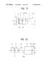
- FIG. 11is a sectional view illustrating a composition of an image pickup system preferred as a seventh embodiment of the present invention.
- FIG. 12is a sectional view illustrating a composition of an image pickup system preferred as an eighth embodiment of the present invention.
- FIG. 13is sectional view illustrating a composition of an image pickup system preferred as a ninth embodiment of the present invention.
- FIG. 14is a diagram illustrating a spectral characteristic of ghost rays in the ninth embodiment of the present invention.
- FIG. 15Ais a diagram illustrating a configuration of an endoscope system preferred as a tenth embodiment of the present invention.
- FIG. 15Bis a diagram showing a white-red mixture color chart to be used in the endoscope system shown in FIG. 15A .
- the image pickup systemcomprises a composite filter described below and a first embodiment of the present invention is characterized by a composition of the composite filter.
- the composite filteris composed as shown in FIG. 3 , wherein a reference symbol F 1 represents an absorption type infrared cut filter and a reference symbol F 2 designates a reflectin type cut coat formed on a surface of the absorption type infrared cut filter F 1 .
- the composite filteris composed by combining two kinds of filters as described above.
- FIG. 4shows a total spectral transmittance characteristic of these filters combined with each other.
- the reflection type filters used for the examinationshad a characteristic to exhibit half a value of transmittance at wavelengths of approximately from 630 to 650 nm and a transmittance of approximately 0% at about 710 nm.
- reflection type filterswhich have the steep characteristic since they cut off visible rays when their cutoff regions are shifted toward a shorter wavelength side.
- the examinationsindicated that a combination only of absorption type infrared cut filters could reduce the horizontal stripe noise and ghost, but provided a color reproducibility lower than that available with the combination only of the reflection type filters.
- the filters used for the examinationsexhibited half a value in the vicinity of approximately 610 nm.
- the composite filter preferred as a first embodiment of the present inventionis composed by combining the absorption type filter F 1 and the reflection type filter F 2 described above as shown in FIG. 3 , and has any one of total spectral characteristics a 1 , a 2 and a 3 shown in FIG. 4 .
- the composite filter preferred as the first embodimentconsists of a first optical element F 1 which is the absorption type filter and a second optical element F 2 which is the reflection type filter, and has the total spectral characteristic shown in FIG. 4 .
- the composite filterswhich have the characteristics a 2 and a 3 permits changing thicknesses t thereof within ranges where the noise and ghost can be reduced while maintaining color reproducibilities at practical levels, characteristics a 2 and a 3 allows a thickness t of a filter.
- a filtermay be thinned or thickened dependently on purposes of use in a field of products of optical instruments or a field of endoscopes in particular.
- a practically usable composite filtercan be composed without degrading a color reproducibility within a range where the above-mentioned condition is satisfied.
- the filter preferred as the first embodiment of the present inventionhas a value of A which is listed below;
- the composite filter preferred as the first embodimenthas a thickness which is listed below:
- the thickness tdoes not strictly define a thickness of the composite filter and a filter is sufficiently usable so far as it satisfies the condition.
- the composite filter according to the present inventionWhen the composite filter according to the present invention is to be used in an endoscope, it is desirable to configure it not only to reduce ghost and noise and enhance a color reproducibility but also to allow the endoscope to be configured compact. It is therefore conceivable to configure the absorption type filter to be thin. When the absorption type filter is configured extremely thin as described above, however, it cannot expect that the composite filter exhibits an effect to reduce ghost and noise.
- a complementary color mosaic filterhas fine filters of Cy, Mg, Ye and G which are arranged in mosaic as described above and problematic noise is largely dependent on a spectral characteristic of Mg. This is because a photodiode has a sensitivity which is relatively high in the near infrared region.
- the composite filter according to the present inventionexhibits a noise reducing effect when it is combined a CCU which has a spectral characteristic of Mg exhibiting transmittance not lower than 50% at 600 nm.
- the composite filtermay be combined with a CCD using a primary color filter which is excellent in a color reproducibility when brightness is not restricted so strictly.
- the composite filter preferred as the first embodiment of the present inventionis capable of cutting rays within a wavelength region of a semiconductor laser beam.
- rays having wavelengths of approximately 700 nm to 830 nm within a wavelength region of the semiconductor laserare unnecessary to form a favorable image and detrimental for the CCD. This is because the CCD itself has a sensitivity covering the wavelength region of the semiconductor laser, thereby skipping white on an image of an object.
- a semiconductor laser cut filteris used to cut off the rays having the wavelengths within the wavelength region of the semiconductor laser in such a case, it is not preferable to use such a filter since it increases a number of filters used.
- the composite filter preferred as the first embodimentis configured to cut off rays having wavelengths of approximately 700 to 830 nm within the wavelength region of the semiconductor laser and exhibits spectral transmittance of approximately 0% in this wavelength region.
- the composite filter preferred as the first embodiment of the present inventionis capable of cutting off laser rays without using another filter even when a semiconductor laser is used. That is, the composite filter is capable of cutting the laser rays simultaneously with the infrared rays, and eliminates the necessity to use a semiconductor laser ray cut filter, thereby making it possible to configure an image pickup system more compact and manufacture it at a lower cost.
- a second embodiment of the composite filter to be used in the image pickup system according to the present inventionhas a composition shown in FIG. 2 , wherein a reference symbol F 1 represents an absorption type filter, and reference symbols F 2 and F 3 designate reflection type filters.
- the second embodimenthas the composition wherein the reflection type filter F 3 is added to the filter preferred as the first embodiment shown in FIG. 3 . That is, the composite filter preferred as the second embodiment consists of a first optical element F 1 which is the absorption type filter, and second and third optical elements F 2 and F 3 which are the reflection type filters.
- the second embodimentis a filter having a configuration which is suited for use not with a semiconductor laser but also a YAG laser.
- the YAG laserhas a wavelength region of approximately 1060 nm which cannot be cut off sufficiently with the composite filter preferred as the first embodiment.
- the second embodiment which comprises the additional reflection type filter F 3has a spectral characteristic illustrated in FIG. 6 .
- the composite filter preferred as the second embodimenthas transmittance of approximately 0 not only in the wavelength region of the semiconductor laser but also in the wavelength region of the YAG laser which is approximately 1060 nm. Taking into manufacturing of the filter into consideration, it is desirable to configure the YAG filter so as to have a cutoff frequency on the order of 1060 ⁇ 20 nm.
- Transmittance T(%) Wavelength(nm) a1 a2 a3 b 380 0.557 0.608 0.456 0.456 390 0.622 0.672 0.518 0.379 400 0.730 0.786 0.615 0.653 410 0.763 0.819 0.647 0.669 420 0.788 0.844 0.673 0.753 430 0.794 0.849 0.680 0.766 440 0.800 0.852 0.689 0.765 450 0.814 0.866 0.703 0.787 460 0.824 0.877 0.714 0.800 470 0.819 0.871 0.711 0.787 480 0.824 0.875 0.716 0.794 490 0.830 0.881 0.723 0.800 500 0.836 0.886 0.729 0.820 510 0.814 0.866 0.705 0.779 520 0.815 0.869 0.701 0.794 530 0.813 0.871 0.691 0.790 540 0.799 0.863 0.668 0.746
- a third embodimentis an objective optical system for endoscopes which uses a composite filter such as the first or second embodiment of the present invention as shown in FIG. 7 .
- This objective optical system for endoscopescomprises, in order from the object side, a negative lens component L 1 , a positive lens component L 2 , a stop S, a positive lens component L 3 and a cover glass plate C, and uses a reflection type filter F 5 disposed between the negative lens component L 1 and the positive lens component L 2 as well as an absorption type filter F 4 disposed between the stop S and the positive lens component L 3 . That is, the third embodiment uses the composite filter which is described above as the second embodiment.
- the objective optical system preferred as the third embodimentis a direct view type optical system which has a field angle of 131° and angle of 0° toward a visual field. Furthermore, a YAG ray cut coating F 6 is formed on an object side surface of the absorption type filter (infrared cut filter) F 4 . Furthermore, the reflection type infrared cut filter F 5 has a function to cut off the semiconductor laser rays.
- reflection type filtersWhen two or more kinds of reflection type filters are to be used as in the image pickup system preferred as the third embodiment, it is necessary to consider locations of the reflection type filters.
- a location of the filtermust be considered when the inclination is large.
- the reflection type filters F 4 and F 4 used in the third embodimentare configured so that an angle of incidence ⁇ (LD) of an offaxial ray incident on the absorption type infrared cut filter which also has a function to cut off the semiconductor laser ray and an angle of incidence ⁇ (Y) of the YAG ray cut coating surface F 6 satisfy the following condition (2): ⁇ ( LD ) ⁇ ( Y ) (2)
- infrared cut filterswhich have cutoff wavelengths in the vicinity of a visible region largely influence on a color reproducibility, it is desirable to dispose these filters at locations where angles of incidence are larger than that on a TAF ray cut coating. It is therefore desirable to satisfy the above-mentioned condition. Furthermore, it is desirable that these angles of incidence are large to a certain degree since ghost may be produced due to multiple reflections between these coated surfaces.
- ⁇ (LD) and ⁇ (Y)are expressed in absolute values in the above-mentioned condition.
- An objective optical system for endoscopes preferred as a fourth embodimentcomprises, in order from the object side as shown in FIG. 8 , a negative lens component L 1 , a cover glass plate C 1 , a 45° prism P, a stop S, a positive lens component L 2 , a positive lens component L 3 , an absorption type infrared cut filter F 7 , a cover glass plate C and a CCD.
- the objective optical system preferred as the fourth embodimentis an optical system which has a field angle of 93° and is configured for forward oblique view.
- An infrared cut coatingwhich has a function to enhance a color reproducibility and another function to cut off the semiconductor laser ray is formed on an object side surface of the absorption type infrared cut filter F 7 used in the optical system preferred as the fourth embodiment. Furthermore, a YAG ray cut coating F 9 is formed on an object side surface of the positive lens component L 2 .
- the fourth embodimentuses the composite filter preferred as the first embodiment (the reflection type filter F 8 is disposed on the absorption type filter F 7 ) in combination with the YAG our coating formed on the positive lens component L 2 .
- the fourth embodimentalso satisfies the above mentioned condition (2).
- ⁇ (LD) and ⁇ (Y)satisfy the following condition (3): ⁇ ( LD ) ⁇ ( Y ) ⁇ 25° (3)
- FIG. 9shows a fifth embodiment of the present invention which is a direct view type objective optical system for endoscopes which has a field angle of 113°, and comprises, in order from the object side, a negative lens component L 1 , a cover glass plate C 1 , a positive lens component L 2 , a stop S, a reflection type infrared cut filter F 11 , an absorption type infrared cut filter F 12 , a positive lens component L 3 , a cover glass plate C 2 , a cover glass plate C and a CCD.
- the fifth embodimentis an objective optical system for endoscopes using the second embodiment which is composed of the reflection type filter F 11 and the absorption type filter F 12 .
- the reflection type cut filter used in this optical systemhas an infrared cut coating having a function to cut off the semiconductor laser which is formed on an object side thereof and a YAG ray cut coating which is formed on a surface thereon on a side of the CCD.
- the fifth embodimentis an example wherein a rear lens unit disposed after the stop S is configured to have a composition as simple as possible to facilitate assembly and simplify a structure of a lens barrel, thereby reducing a manufacturing cost.
- angles of incidence of rays on the filtersare sufficiently smaller than those defined by the condition (3).
- the angles of incidenceare sufficiently small as in the fifth embodiment, influences due to inclination angles of incident rays are small and it is not always necessary to satisfy the condition (2).
- angles of incidence of rays on the coatingsare nearly equal to each other, and the infrared cut coating having a function to cut off the semiconductor laser ray and the YAG ray cut coating may be formed on either of the surfaces on the reflection type infrared cut filter.
- FIG. 10shows a sixth embodiment, which comprises, in order from the object side, a negative lens component L 1 , a stop S, a positive lens component L 2 , a positive lens component L 3 , an absorption type cut filter F 13 , a cover glass plate C and a CCD: an infrared cut coating F 14 having a function to cut off the semiconductor laser ray being formed on a surface of the positive lens component L 3 which is on a side of the CCD and a YAG ray cut coating F 15 being formed on an object side surface of the absorption type infrared cut filter F 13 .
- the sixth embodimentis an example wherein the YAG cut coating F 15 is additionally formed on the composite filter preferred as the second embodiment which consists of the absorption type filter F 13 and the reflection type filter F 14 .
- the sixth embodimentis an example wherein the angles ⁇ (LD) and ⁇ (Y) are made sufficiently small.
- the sixth embodimentis characterized in that it has a simpler composition and is configured more compact.
- the stop Sis disposed at a location shifted toward the object side, and stronger powers are imparted to the positive lens components L 2 and L 3 to configure the sixth embodiment to be more compact and thinner.
- a mask M which restricts a visual field and prevent detrimental raysis formed by depositing chromium on a surface of the absorption type infrared filter F 13 on the side of the CCD. Owing to the configuration described above, the sixth embodiment has the simpler composition as described and can be assembled more easily.
- the sixth embodimentis a direct view type objective optical system for endoscopes having a field angle of 114°.
- FIG. 11is a sectional view illustrating an optical system preferred as a seventh embodiment, which comprises, in order from the object side, a negative lens component L 1 , a stop S, a positive lens component L 2 , a lens (infrared cut lens) component L 3 , a CCD cover glass plate C and a CCD.
- the seventh embodimentuses the positive lens component L 3 having an infrared cut function as a filter F 16 .
- curvatureis imparted to an absorption type infrared cut filter so that it functions as a positive lens component.
- This infrared cut filtermakes it to possible to save a space to dispose a filter, thereby making the optical system and a tip of an endoscope more compact.
- a YAG laser cut coatingis formed on an object side surface of the positive lens component L 2 and a reflection type infrared cut coating F 17 is formed on an object side surface of the infrared cut lens F 16 (positive lens component L 3 ). Furthermore, it is possible to configure this reflection type infrared cut coating F 16 so as to have a semiconductor laser ray cut function.
- the absorption type infrared cut filter F 16may be manufactured by a sol-gel method. This method enhances water resistance, abrasion resistance and a workability of the filter. When an absorption type infrared cut filter is worked so as to have a spherical surface as in the seventh embodiment, the sol-gel method effectively enhances a workability of the filter.
- FIG. 12is a sectional view illustrating an eighth embodiment of the present invention, which comprises, in order from the object side, a negative lens component L 1 , a stop S, a positive lens component L 2 , a positive lens component L 3 , an absorption type YAG ray cut filter F 21 , an absorption type infrared cut filter F 19 and a CCD. Furthermore, a reflection type infrared cut coating F 20 is formed on a surface of the positive lens component L 3 which is located on a side of the CCD.
- an optical system preferred as the eighth embodimentuses a composite filter which consists, like the filter in the second embodiment, of the absorption type infrared cut filter F 19 , the reflection type infrared cut filter F 20 disposed on the positive lens component L 3 and the absorption type cut filter F 21 .
- the composite cut filter used in the eighth embodimentconsists of a first optical element F 19 which is the absorption type cut filter, a second optical element F 20 which is the reflection type cut filter and a third optical element F 21 which is the absorption type cut filter.
- the eighth embodimentis an example wherein ghost and flare are reduced by disposing the absorption type infrared cut filter F 19 and the YAG ray cut filter F 21 .
- the reflection type infrared cut coatingis formed on the surface of the positive lens component L 3 which is located on the side of the CCD.
- Infrared Cut Filter HA-15prepared by HOYA is used as the absorption type YAG ray cut filter F 21 which can cut off infrared rays having a wavelength region from 1000 nm to 1200 nm.
- 11A-30 prepared by HOYA having a smaller absorption coefficient for infrared raysmay be used with an endoscope which has a margin in a size (length) of its tip.
- FIG. 13illustrates a ninth embodiment.
- the ninth embodimentis an example wherein a reflection type infrared out filter is used in a TV adaptor for endoscopes.
- the ninth embodimentcomprises, in order from the object side as shown in FIG. 13 , a cover glass plate C 3 , an imaging lens system IL which consists of a positive lens component, a negative lens component and a positive lens component, a cover glass plate C 4 , a cover glass plate C 5 , a filter group FG, a CCD cover glass plate C and a CCD.
- an imaging lens system ILwhich consists of a positive lens component, a negative lens component and a positive lens component
- a cover glass plate C 4a cover glass plate C 5
- a filter group FGa CCD cover glass plate C and a CCD.
- a filter F 22which is disposed on the object side in the filter group FG and has an infrared cut coating F 23 formed thereon functions so that a light bundle which is incident from the object side and has passed through the infrared cut coating F 23 is reflected by a surface having high reflectance such as the CCD cover glass plate C and then is reflected once again by the infrared cut coating, thereafter being incident on an image pickup surface of the CCD a ghost.
- FIG. 14shows a spectral curve of a reflection type infrared cut filter.
- transmittance of a coating surfaceis represented by ⁇
- reflectance of the coating surfaceis designated by (1 ⁇ )
- transmittance for ghost raysis approximately expressed as r ⁇ (1 ⁇ )
- an intensity distributionis as indicated in a portion C of FIG. 14 .
- the ghost rayscan be reduced by narrowing an area of the portion C of FIG. 14 . In other words, it is sufficient for reducing ghost rays to make an inclination of the spectral curve steeper in a cutoff region ⁇ W ⁇ .
- At least a reflection type infrared cut filter of a composite filter to be used in the ninth embodimenthas a cutoff frequency region ⁇ W ⁇ of 610 nm to 650 nm at which it exhibits transmittance not higher than 10% as well as transmittance not lower than 50% at a wavelength of 610 nm and transmittance not higher than 10% at a wavelength of 650 nm.
- condition described aboveis defined taking into consideration manufacturing errors of the filters and shifts of spectral characteristics dependent on angles of incidence on a coating.
- the cutoff wavelength regionis apt to be generally narrowed by making the inclination of the spectral curve steeper and it is effective for reducing ghost and noise to combine the reflection type infrared cut filter with an absorption type infrared cut filter, thereby composing a composite filter.
- FIG. 15Ashows an endoscope system consisting of endoscopes which adopt the composite filter preferred as the first embodiment of the present invention.
- This systemcontrols a plurality of endoscopes with a single CCU (camera control unit) as shown in FIG. 15A .
- a reference numeral 10represents an endoscopes set which consists of a plurality of endoscopes E 1 , E 2 , . . . a reference numeral 11 designates the CCU
- a reference numeral 12denotes a light source
- a reference numeral 13represents a signal cable including a light guide cable
- a reference numeral 14designates a TV monitor.
- the endoscope systemis equipped with the plurality of endoscopes E 1 , E 2 , . . . which have specifications optimum for needs in fields of products of optical instruments.
- the absorption type infrared cut filterswhich are relatively inexpensive are mainly used, for example, in a medical endoscope for digestive systems and an external TV camera whose sizes are little restricted.
- the reflection type filtersare used to meet a demand for a compact design.
- CCDs optimum for respective fields of products of optical instrumentsare used. It is therefore required to compose an endoscope such as that shown in FIG. 15A .
- the plurality of endoscopes to be used in such an endoscope systemuse different kinds of filters and different kinds of CCDs, whereby the endoscopes have different color reproducibilities and can hardly be controlled with a single CCU.
- an endoscope systemsuch as that described above, it is effective to use the composite filter according to the present invention for each of a plurality of endoscopes. It is desirable, for example, to optimalize a spectral characteristic of the composite filter to each endoscope so as to nearly equalize color reproducibilities of endoscope images which are to be finally obtained.
- the composite filter according to the present inventionpermits modifying its spectral characteristic since it is composed of the reflection type and the absorption type filters which have different spectral characteristics. For such a modification of the spectral characteristic of the composite filter it is possible to change a thickness of the absorption type filter and only a film configuration of the reflection type filter.
- a plurality of color matrix circuitsmay be prepared on the side of the CCU so that an endoscope system can selects a color matrix circuit optimum for each product.
- an endoscope systemmay be configured to select an electric resistor in a CCD connector for each endoscope and select a color matrix by detecting a signal from the electric resistor on the side of the CCU.
- the endoscope systemmay be configured to be capable of selecting color matrices which are customized by a user for ways of use.
- a white chart or the likeis usually used for manual color correction
- a white-red mixture color chart(for example R is red and W is white) such as that shown in FIG. 15B may be used.
- the image pickup apparatuswhich uses the composite filter having the total spectral characteristic is capable of enhancing a color reproducibility, produces little ghost and flare, and reducing electric noise.
- the endoscope system according to the present inventionis capable of obtaining which is nearly constant even when it uses any one of a plurality of different kinds of endoscopes.
Landscapes
- Physics & Mathematics (AREA)
- Life Sciences & Earth Sciences (AREA)
- Health & Medical Sciences (AREA)
- Surgery (AREA)
- Optics & Photonics (AREA)
- Engineering & Computer Science (AREA)
- Heart & Thoracic Surgery (AREA)
- General Physics & Mathematics (AREA)
- Nuclear Medicine, Radiotherapy & Molecular Imaging (AREA)
- Biophysics (AREA)
- Pathology (AREA)
- Radiology & Medical Imaging (AREA)
- Veterinary Medicine (AREA)
- Biomedical Technology (AREA)
- Public Health (AREA)
- Medical Informatics (AREA)
- Molecular Biology (AREA)
- Animal Behavior & Ethology (AREA)
- General Health & Medical Sciences (AREA)
- Multimedia (AREA)
- Signal Processing (AREA)
- Spectroscopy & Molecular Physics (AREA)
- Astronomy & Astrophysics (AREA)
- Endoscopes (AREA)
- Closed-Circuit Television Systems (AREA)
- Color Television Image Signal Generators (AREA)
- Instruments For Viewing The Inside Of Hollow Bodies (AREA)
- Optical Filters (AREA)
Abstract
Description
- First line: Ye, Cy, Ye, Cy
- Second line: Mg, G, Mg, G
- Third line: Ye, Cy, Ye, Cy
- Fourth line: G, Mg, G, Mg
0.45≦|ΔT/ΔW|≦0.75 (1)
wherein the reference symbol ΔT represents a difference between transmittance T(600) at a wavelength of 600 nm and transmittance T (550) at a wavelength of 550 nm, or ΔT(%)=T (600)−T (550), and the reference symbol ΔW designates 50 nm.
A=|ΔT(a1)/ΔW|=|(46.72−76.36)/50|≈0.59
A=|ΔT(a2)/ΔW|=|(61.06−83.54)/50|≈0.45
A=|ΔT(a3)/ΔW|=|(25.01−61.93)/50|≈0.74
t=1.6 mm
t=1 mm
t=3 mm
0.35≦A≦0.75 (1—1)
| Transmittance T (%) |
| Wavelength(nm) | a1 | a2 | a3 | b |
| 380 | 0.557 | 0.608 | 0.456 | 0.456 |
| 390 | 0.622 | 0.672 | 0.518 | 0.379 |
| 400 | 0.730 | 0.786 | 0.615 | 0.653 |
| 410 | 0.763 | 0.819 | 0.647 | 0.669 |
| 420 | 0.788 | 0.844 | 0.673 | 0.753 |
| 430 | 0.794 | 0.849 | 0.680 | 0.766 |
| 440 | 0.800 | 0.852 | 0.689 | 0.765 |
| 450 | 0.814 | 0.866 | 0.703 | 0.787 |
| 460 | 0.824 | 0.877 | 0.714 | 0.800 |
| 470 | 0.819 | 0.871 | 0.711 | 0.787 |
| 480 | 0.824 | 0.875 | 0.716 | 0.794 |
| 490 | 0.830 | 0.881 | 0.723 | 0.800 |
| 500 | 0.836 | 0.886 | 0.729 | 0.820 |
| 510 | 0.814 | 0.866 | 0.705 | 0.779 |
| 520 | 0.815 | 0.869 | 0.701 | 0.794 |
| 530 | 0.813 | 0.871 | 0.691 | 0.790 |
| 540 | 0.799 | 0.863 | 0.668 | 0.746 |
| 550 | 0.764 | 0.835 | 0.619 | 0.704 |
| 560 | 0.723 | 0.807 | 0.560 | 0.690 |
| 570 | 0.680 | 0.779 | 0.495 | 0.663 |
| 580 | 0.624 | 0.739 | 0.419 | 0.612 |
| 590 | 0.544 | 0.674 | 0.330 | 0.538 |
| 600 | 0.467 | 0.611 | 0.250 | 0.461 |
| 610 | 0.401 | 0.560 | 0.184 | 0.398 |
| 620 | 0.286 | 0.432 | 0.109 | 0.283 |
| 630 | 0.152 | 0.252 | 0.047 | 0.152 |
| 640 | 0.045 | 0.082 | 0.011 | 0.045 |
| 650 | 0.013 | 0.027 | 0.003 | 0.013 |
| 660 | 0.006 | 0.014 | 0.001 | 0.006 |
| 670 | 0.003 | 0.008 | 0.000 | 0.003 |
| 680 | 0.001 | 0.003 | 0.000 | 0.001 |
| 690 | 0.000 | 0.001 | 0.000 | 0.000 |
| 700 | 0.000 | 0.001 | 0.000 | 0.000 |
| 710 | 0.000 | 0.001 | 0.000 | 0.000 |
| 720 | 0.000 | 0.001 | 0.000 | 0.000 |
| 730 | 0.000 | 0.000 | 0.000 | 0.000 |
| 740 | 0.000 | 0.000 | 0.000 | 0.000 |
| 750 | 0.000 | 0.000 | 0.000 | 0.000 |
| 760 | 0.000 | 0.000 | 0.000 | 0.000 |
| 770 | 0.000 | 0.000 | 0.000 | 0.000 |
| 780 | 0.000 | 0.000 | 0.000 | 0.000 |
| 790 | 0.000 | 0.000 | 0.000 | 0.000 |
| 800 | 0.000 | 0.000 | 0.000 | 0.000 |
| 810 | 0.000 | 0.000 | 0.000 | 0.000 |
| 820 | 0.000 | 0.000 | 0.000 | 0.000 |
| 830 | 0.000 | 0.000 | 0.000 | 0.000 |
| 840 | 0.000 | 0.000 | 0.000 | 0.000 |
| 850 | 0.000 | 0.000 | 0.000 | 0.000 |
| 860 | 0.000 | 0.000 | 0.000 | 0.000 |
| 870 | 0.000 | 0.000 | 0.000 | 0.000 |
| 880 | 0.000 | 0.000 | 0.000 | 0.000 |
| 890 | 0.000 | 0.000 | 0.000 | 0.000 |
| 900 | 0.000 | 0.000 | 0.000 | 0.000 |
| 910 | 0.000 | 0.000 | 0.000 | 0.000 |
| 920 | 0.000 | 0.000 | 0.000 | 0.000 |
| 930 | 0.000 | 0.000 | 0.000 | 0.000 |
| 940 | 0.000 | 0.000 | 0.000 | 0.000 |
| 950 | 0.000 | 0.000 | 0.000 | 0.000 |
| 960 | 0.000 | 0.000 | 0.000 | 0.000 |
| 970 | 0.000 | 0.001 | 0.000 | 0.000 |
| 980 | 0.000 | 0.001 | 0.000 | 0.000 |
| 990 | 0.000 | 0.001 | 0.000 | 0.000 |
| 1000 | 0.000 | 0.001 | 0.000 | 0.000 |
| 1010 | 0.000 | 0.001 | 0.000 | 0.000 |
| 1020 | 0.000 | 0.002 | 0.000 | 0.000 |
| 1030 | 0.000 | 0.002 | 0.000 | 0.000 |
| 1040 | 0.001 | 0.003 | 0.000 | 0.000 |
| 1050 | 0.001 | 0.004 | 0.000 | 0.000 |
| 1060 | 0.002 | 0.007 | 0.000 | 0.000 |
| 1070 | 0.003 | 0.013 | 0.000 | 0.000 |
| 1080 | 0.006 | 0.025 | 0.000 | 0.000 |
| 1090 | 0.011 | 0.043 | 0.001 | 0.000 |
| 1100 | 0.016 | 0.061 | 0.001 | 0.000 |
| 1110 | 0.020 | 0.072 | 0.001 | 0.000 |
| 1120 | 0.023 | 0.079 | 0.001 | 0.000 |
| 1130 | 0.027 | 0.089 | 0.002 | 0.000 |
| 1140 | 0.033 | 0.104 | 0.002 | 0.000 |
| 1150 | 0.041 | 0.125 | 0.003 | 0.000 |
| 1160 | 0.049 | 0.144 | 0.004 | 0.000 |
| 1170 | 0.055 | 0.154 | 0.005 | 0.000 |
| 1180 | 0.056 | 0.154 | 0.005 | 0.000 |
| 1190 | 0.056 | 0.148 | 0.006 | 0.000 |
| 1200 | 0.056 | 0.144 | 0.006 | 0.001 |
θ(LD)<θ(Y) (2)
θ(LD)<θ(Y)≦25° (3)
Claims (14)
0.45≦|ΔT/ΔW|≦0.75 (1)
ΔT=T(600)−T(550), and
θ(LD)<θ(Y) (2)
θ(LD)<θ(Y)≦25° (3).
0.45≦|ΔT/ΔW|≦0.75, (1)
ΔT=T(600)−T(550), and
0.35≦A≦0.75 (1—1)
Applications Claiming Priority (1)
| Application Number | Priority Date | Filing Date | Title |
|---|---|---|---|
| JP32295598AJP2000137172A (en) | 1998-10-29 | 1998-10-29 | Image pickup device |
Publications (1)
| Publication Number | Publication Date |
|---|---|
| US6985170B1true US6985170B1 (en) | 2006-01-10 |
Family
ID=18149515
Family Applications (1)
| Application Number | Title | Priority Date | Filing Date |
|---|---|---|---|
| US09/430,074Expired - Fee RelatedUS6985170B1 (en) | 1998-10-29 | 1999-10-29 | Image pickup apparatus |
Country Status (2)
| Country | Link |
|---|---|
| US (1) | US6985170B1 (en) |
| JP (1) | JP2000137172A (en) |
Cited By (40)
| Publication number | Priority date | Publication date | Assignee | Title |
|---|---|---|---|---|
| US20040080613A1 (en)* | 2002-10-25 | 2004-04-29 | Olympus Optical Co., Ltd. | Endoscope system |
| US20040099827A1 (en)* | 2002-11-25 | 2004-05-27 | Fuji Photo Film Co., Ltd. | Radiation image read-out apparatus and radiation image convertor panel |
| US20050084774A1 (en)* | 2003-08-05 | 2005-04-21 | Canon Kabushiki Kaisha | Production process of light amount-adjusting member, light amount-adjusting member, light amount-adjusting device and photographing apparatus |
| US20050218308A1 (en)* | 2004-03-30 | 2005-10-06 | Eastman Kodak Company | Electronic imagers using an absorbing filter for flare reduction |
| US20100182464A1 (en)* | 2009-01-21 | 2010-07-22 | Rastislav Lukac | Joint Automatic Demosaicking And White Balancing |
| US20120190923A1 (en)* | 2009-09-30 | 2012-07-26 | Siemens Aktiengesellschaft | Endoscope |
| US20130258082A1 (en)* | 2012-03-30 | 2013-10-03 | Fujifilm Corporation | Stripe noise correction method of captured image, photographing apparatus and electronic endoscopic apparatus |
| US9101287B2 (en) | 2011-03-07 | 2015-08-11 | Endochoice Innovation Center Ltd. | Multi camera endoscope assembly having multiple working channels |
| US9101268B2 (en) | 2009-06-18 | 2015-08-11 | Endochoice Innovation Center Ltd. | Multi-camera endoscope |
| US9101266B2 (en) | 2011-02-07 | 2015-08-11 | Endochoice Innovation Center Ltd. | Multi-element cover for a multi-camera endoscope |
| US9314147B2 (en) | 2011-12-13 | 2016-04-19 | Endochoice Innovation Center Ltd. | Rotatable connector for an endoscope |
| US9320419B2 (en) | 2010-12-09 | 2016-04-26 | Endochoice Innovation Center Ltd. | Fluid channeling component of a multi-camera endoscope |
| US9402533B2 (en) | 2011-03-07 | 2016-08-02 | Endochoice Innovation Center Ltd. | Endoscope circuit board assembly |
| US9492063B2 (en) | 2009-06-18 | 2016-11-15 | Endochoice Innovation Center Ltd. | Multi-viewing element endoscope |
| US9554692B2 (en) | 2009-06-18 | 2017-01-31 | EndoChoice Innovation Ctr. Ltd. | Multi-camera endoscope |
| US9560954B2 (en) | 2012-07-24 | 2017-02-07 | Endochoice, Inc. | Connector for use with endoscope |
| US9560953B2 (en) | 2010-09-20 | 2017-02-07 | Endochoice, Inc. | Operational interface in a multi-viewing element endoscope |
| US9642513B2 (en) | 2009-06-18 | 2017-05-09 | Endochoice Inc. | Compact multi-viewing element endoscope system |
| US9655502B2 (en) | 2011-12-13 | 2017-05-23 | EndoChoice Innovation Center, Ltd. | Removable tip endoscope |
| US9706903B2 (en) | 2009-06-18 | 2017-07-18 | Endochoice, Inc. | Multiple viewing elements endoscope system with modular imaging units |
| US9713417B2 (en) | 2009-06-18 | 2017-07-25 | Endochoice, Inc. | Image capture assembly for use in a multi-viewing elements endoscope |
| US9713415B2 (en) | 2011-03-07 | 2017-07-25 | Endochoice Innovation Center Ltd. | Multi camera endoscope having a side service channel |
| US9814374B2 (en) | 2010-12-09 | 2017-11-14 | Endochoice Innovation Center Ltd. | Flexible electronic circuit board for a multi-camera endoscope |
| US9872609B2 (en) | 2009-06-18 | 2018-01-23 | Endochoice Innovation Center Ltd. | Multi-camera endoscope |
| US9901244B2 (en) | 2009-06-18 | 2018-02-27 | Endochoice, Inc. | Circuit board assembly of a multiple viewing elements endoscope |
| US9986899B2 (en) | 2013-03-28 | 2018-06-05 | Endochoice, Inc. | Manifold for a multiple viewing elements endoscope |
| US9993142B2 (en) | 2013-03-28 | 2018-06-12 | Endochoice, Inc. | Fluid distribution device for a multiple viewing elements endoscope |
| US10080486B2 (en) | 2010-09-20 | 2018-09-25 | Endochoice Innovation Center Ltd. | Multi-camera endoscope having fluid channels |
| US10165929B2 (en) | 2009-06-18 | 2019-01-01 | Endochoice, Inc. | Compact multi-viewing element endoscope system |
| US10203493B2 (en) | 2010-10-28 | 2019-02-12 | Endochoice Innovation Center Ltd. | Optical systems for multi-sensor endoscopes |
| US10365417B2 (en) | 2015-01-14 | 2019-07-30 | AGC Inc. | Near-infrared cut filter and imaging device |
| US10499794B2 (en) | 2013-05-09 | 2019-12-10 | Endochoice, Inc. | Operational interface in a multi-viewing element endoscope |
| US10893793B2 (en) | 2016-05-27 | 2021-01-19 | Olympus Corporation | Objective optical system and endoscope device including the same |
| US11278190B2 (en) | 2009-06-18 | 2022-03-22 | Endochoice, Inc. | Multi-viewing element endoscope |
| US11547275B2 (en) | 2009-06-18 | 2023-01-10 | Endochoice, Inc. | Compact multi-viewing element endoscope system |
| US11864734B2 (en) | 2009-06-18 | 2024-01-09 | Endochoice, Inc. | Multi-camera endoscope |
| US11889986B2 (en) | 2010-12-09 | 2024-02-06 | Endochoice, Inc. | Flexible electronic circuit board for a multi-camera endoscope |
| US12137873B2 (en) | 2009-06-18 | 2024-11-12 | Endochoice, Inc. | Compact multi-viewing element endoscope system |
| US12204087B2 (en) | 2010-10-28 | 2025-01-21 | Endochoice, Inc. | Optical systems for multi-sensor endoscopes |
| US12220105B2 (en) | 2010-06-16 | 2025-02-11 | Endochoice, Inc. | Circuit board assembly of a multiple viewing elements endoscope |
Families Citing this family (2)
| Publication number | Priority date | Publication date | Assignee | Title |
|---|---|---|---|---|
| GB2423589A (en)* | 2005-02-23 | 2006-08-30 | Univ Warwick | Wireless communication receiver with optical diverging element and filter |
| JP2007279750A (en)* | 2007-04-13 | 2007-10-25 | Nec Corp | Incidence preventing film forming method of condenser lens |
Citations (13)
| Publication number | Priority date | Publication date | Assignee | Title |
|---|---|---|---|---|
| JPS6412547A (en) | 1987-07-07 | 1989-01-17 | Fujitsu Ltd | Formation of multilayer interconnection |
| US4816909A (en)* | 1986-12-17 | 1989-03-28 | Olympus Optical Co., Ltd. | Video endoscope system for use with different sizes of solid state devices |
| US4916534A (en)* | 1987-04-28 | 1990-04-10 | Olympus Optical Co., Ltd. | Endoscope |
| US4977450A (en)* | 1988-11-18 | 1990-12-11 | Olympus Optical Co., Ltd. | Image pickup system for an endoscope using a first filter matched to a frequency of a fiber array and a second matched to a frequency of an image pickup device |
| US5177605A (en) | 1987-04-28 | 1993-01-05 | Olympus Optical Co., Ltd. | Optical system for endoscopes and endoscopes using same |
| US5514127A (en)* | 1993-02-18 | 1996-05-07 | Central Research Laboratories Limited | Apparatus for irradiating an area with a controllable pattern of light |
| US5997472A (en)* | 1995-04-14 | 1999-12-07 | Vipera Systems, Inc. | Endodiagnostic method using differential thermal relaxation and IR imaging |
| US6028622A (en)* | 1997-04-25 | 2000-02-22 | Olympus Optical Co., Ltd. | Observation apparatus for endoscopes |
| US6099146A (en)* | 1997-02-04 | 2000-08-08 | Olympus Optical Company, Ltd. | Illuminating optical system for cutting infrared light by relief type optical element |
| US6124883A (en)* | 1996-02-26 | 2000-09-26 | Olympus Optical Co., Ltd. | TV observation system for endoscopes |
| US6148227A (en)* | 1998-01-07 | 2000-11-14 | Richard Wolf Gmbh | Diagnosis apparatus for the picture providing recording of fluorescing biological tissue regions |
| US6293911B1 (en)* | 1996-11-20 | 2001-09-25 | Olympus Optical Co., Ltd. | Fluorescent endoscope system enabling simultaneous normal light observation and fluorescence observation in infrared spectrum |
| US6537211B1 (en)* | 1998-01-26 | 2003-03-25 | Massachusetts Institute Of Technology | Flourescence imaging endoscope |
- 1998
- 1998-10-29JPJP32295598Apatent/JP2000137172A/ennot_activeWithdrawn
- 1999
- 1999-10-29USUS09/430,074patent/US6985170B1/ennot_activeExpired - Fee Related
Patent Citations (13)
| Publication number | Priority date | Publication date | Assignee | Title |
|---|---|---|---|---|
| US4816909A (en)* | 1986-12-17 | 1989-03-28 | Olympus Optical Co., Ltd. | Video endoscope system for use with different sizes of solid state devices |
| US4916534A (en)* | 1987-04-28 | 1990-04-10 | Olympus Optical Co., Ltd. | Endoscope |
| US5177605A (en) | 1987-04-28 | 1993-01-05 | Olympus Optical Co., Ltd. | Optical system for endoscopes and endoscopes using same |
| JPS6412547A (en) | 1987-07-07 | 1989-01-17 | Fujitsu Ltd | Formation of multilayer interconnection |
| US4977450A (en)* | 1988-11-18 | 1990-12-11 | Olympus Optical Co., Ltd. | Image pickup system for an endoscope using a first filter matched to a frequency of a fiber array and a second matched to a frequency of an image pickup device |
| US5514127A (en)* | 1993-02-18 | 1996-05-07 | Central Research Laboratories Limited | Apparatus for irradiating an area with a controllable pattern of light |
| US5997472A (en)* | 1995-04-14 | 1999-12-07 | Vipera Systems, Inc. | Endodiagnostic method using differential thermal relaxation and IR imaging |
| US6124883A (en)* | 1996-02-26 | 2000-09-26 | Olympus Optical Co., Ltd. | TV observation system for endoscopes |
| US6293911B1 (en)* | 1996-11-20 | 2001-09-25 | Olympus Optical Co., Ltd. | Fluorescent endoscope system enabling simultaneous normal light observation and fluorescence observation in infrared spectrum |
| US6099146A (en)* | 1997-02-04 | 2000-08-08 | Olympus Optical Company, Ltd. | Illuminating optical system for cutting infrared light by relief type optical element |
| US6028622A (en)* | 1997-04-25 | 2000-02-22 | Olympus Optical Co., Ltd. | Observation apparatus for endoscopes |
| US6148227A (en)* | 1998-01-07 | 2000-11-14 | Richard Wolf Gmbh | Diagnosis apparatus for the picture providing recording of fluorescing biological tissue regions |
| US6537211B1 (en)* | 1998-01-26 | 2003-03-25 | Massachusetts Institute Of Technology | Flourescence imaging endoscope |
Cited By (78)
| Publication number | Priority date | Publication date | Assignee | Title |
|---|---|---|---|---|
| US20040080613A1 (en)* | 2002-10-25 | 2004-04-29 | Olympus Optical Co., Ltd. | Endoscope system |
| EP1554972A4 (en)* | 2002-10-25 | 2008-03-12 | Olympus Corp | Endoscope device |
| US20040099827A1 (en)* | 2002-11-25 | 2004-05-27 | Fuji Photo Film Co., Ltd. | Radiation image read-out apparatus and radiation image convertor panel |
| US20070164242A1 (en)* | 2002-11-25 | 2007-07-19 | Fuji Photo Film Co., Ltd. | Radiation image read-out apparatus and radiation image convertor panel |
| US7446332B2 (en) | 2002-11-25 | 2008-11-04 | Fujifilm Corporation | Radiation image read-out apparatus and radiation image convertor panel |
| US20050084774A1 (en)* | 2003-08-05 | 2005-04-21 | Canon Kabushiki Kaisha | Production process of light amount-adjusting member, light amount-adjusting member, light amount-adjusting device and photographing apparatus |
| US7189014B2 (en)* | 2003-08-05 | 2007-03-13 | Canon Kabushiki Kaisha | Production process of light amount-adjusting member, light amount-adjusting member, light amount-adjusting device and photographing apparatus |
| US20050218308A1 (en)* | 2004-03-30 | 2005-10-06 | Eastman Kodak Company | Electronic imagers using an absorbing filter for flare reduction |
| US20100182464A1 (en)* | 2009-01-21 | 2010-07-22 | Rastislav Lukac | Joint Automatic Demosaicking And White Balancing |
| US8035698B2 (en) | 2009-01-21 | 2011-10-11 | Seiko Epson Corporation | Joint automatic demosaicking and white balancing |
| US11864734B2 (en) | 2009-06-18 | 2024-01-09 | Endochoice, Inc. | Multi-camera endoscope |
| US9872609B2 (en) | 2009-06-18 | 2018-01-23 | Endochoice Innovation Center Ltd. | Multi-camera endoscope |
| US12303106B2 (en) | 2009-06-18 | 2025-05-20 | Endochoice, Inc. | Multi-camera endoscope |
| US9101268B2 (en) | 2009-06-18 | 2015-08-11 | Endochoice Innovation Center Ltd. | Multi-camera endoscope |
| US10912445B2 (en) | 2009-06-18 | 2021-02-09 | Endochoice, Inc. | Compact multi-viewing element endoscope system |
| US10791910B2 (en) | 2009-06-18 | 2020-10-06 | Endochoice, Inc. | Multiple viewing elements endoscope system with modular imaging units |
| US12137873B2 (en) | 2009-06-18 | 2024-11-12 | Endochoice, Inc. | Compact multi-viewing element endoscope system |
| US10791909B2 (en) | 2009-06-18 | 2020-10-06 | Endochoice, Inc. | Image capture assembly for use in a multi-viewing elements endoscope |
| US10165929B2 (en) | 2009-06-18 | 2019-01-01 | Endochoice, Inc. | Compact multi-viewing element endoscope system |
| US11986155B2 (en) | 2009-06-18 | 2024-05-21 | Endochoice, Inc. | Multi-viewing element endoscope |
| US9492063B2 (en) | 2009-06-18 | 2016-11-15 | Endochoice Innovation Center Ltd. | Multi-viewing element endoscope |
| US9554692B2 (en) | 2009-06-18 | 2017-01-31 | EndoChoice Innovation Ctr. Ltd. | Multi-camera endoscope |
| US10765305B2 (en) | 2009-06-18 | 2020-09-08 | Endochoice, Inc. | Circuit board assembly of a multiple viewing elements endoscope |
| US10092167B2 (en) | 2009-06-18 | 2018-10-09 | Endochoice, Inc. | Multiple viewing elements endoscope system with modular imaging units |
| US9642513B2 (en) | 2009-06-18 | 2017-05-09 | Endochoice Inc. | Compact multi-viewing element endoscope system |
| US10799095B2 (en) | 2009-06-18 | 2020-10-13 | Endochoice, Inc. | Multi-viewing element endoscope |
| US9706905B2 (en) | 2009-06-18 | 2017-07-18 | Endochoice Innovation Center Ltd. | Multi-camera endoscope |
| US9706903B2 (en) | 2009-06-18 | 2017-07-18 | Endochoice, Inc. | Multiple viewing elements endoscope system with modular imaging units |
| US9713417B2 (en) | 2009-06-18 | 2017-07-25 | Endochoice, Inc. | Image capture assembly for use in a multi-viewing elements endoscope |
| US11547275B2 (en) | 2009-06-18 | 2023-01-10 | Endochoice, Inc. | Compact multi-viewing element endoscope system |
| US10638922B2 (en) | 2009-06-18 | 2020-05-05 | Endochoice, Inc. | Multi-camera endoscope |
| US12336686B2 (en) | 2009-06-18 | 2025-06-24 | Endochoice, Inc. | Multi-viewing element endoscope |
| US11278190B2 (en) | 2009-06-18 | 2022-03-22 | Endochoice, Inc. | Multi-viewing element endoscope |
| US9901244B2 (en) | 2009-06-18 | 2018-02-27 | Endochoice, Inc. | Circuit board assembly of a multiple viewing elements endoscope |
| US11534056B2 (en) | 2009-06-18 | 2022-12-27 | Endochoice, Inc. | Multi-camera endoscope |
| US11471028B2 (en) | 2009-06-18 | 2022-10-18 | Endochoice, Inc. | Circuit board assembly of a multiple viewing elements endoscope |
| US10905320B2 (en) | 2009-06-18 | 2021-02-02 | Endochoice, Inc. | Multi-camera endoscope |
| US20120190923A1 (en)* | 2009-09-30 | 2012-07-26 | Siemens Aktiengesellschaft | Endoscope |
| US12220105B2 (en) | 2010-06-16 | 2025-02-11 | Endochoice, Inc. | Circuit board assembly of a multiple viewing elements endoscope |
| US9986892B2 (en) | 2010-09-20 | 2018-06-05 | Endochoice, Inc. | Operational interface in a multi-viewing element endoscope |
| US10080486B2 (en) | 2010-09-20 | 2018-09-25 | Endochoice Innovation Center Ltd. | Multi-camera endoscope having fluid channels |
| US9560953B2 (en) | 2010-09-20 | 2017-02-07 | Endochoice, Inc. | Operational interface in a multi-viewing element endoscope |
| US11543646B2 (en) | 2010-10-28 | 2023-01-03 | Endochoice, Inc. | Optical systems for multi-sensor endoscopes |
| US10203493B2 (en) | 2010-10-28 | 2019-02-12 | Endochoice Innovation Center Ltd. | Optical systems for multi-sensor endoscopes |
| US12204087B2 (en) | 2010-10-28 | 2025-01-21 | Endochoice, Inc. | Optical systems for multi-sensor endoscopes |
| US10182707B2 (en) | 2010-12-09 | 2019-01-22 | Endochoice Innovation Center Ltd. | Fluid channeling component of a multi-camera endoscope |
| US11497388B2 (en) | 2010-12-09 | 2022-11-15 | Endochoice, Inc. | Flexible electronic circuit board for a multi-camera endoscope |
| US10898063B2 (en) | 2010-12-09 | 2021-01-26 | Endochoice, Inc. | Flexible electronic circuit board for a multi camera endoscope |
| US9814374B2 (en) | 2010-12-09 | 2017-11-14 | Endochoice Innovation Center Ltd. | Flexible electronic circuit board for a multi-camera endoscope |
| US11889986B2 (en) | 2010-12-09 | 2024-02-06 | Endochoice, Inc. | Flexible electronic circuit board for a multi-camera endoscope |
| US9320419B2 (en) | 2010-12-09 | 2016-04-26 | Endochoice Innovation Center Ltd. | Fluid channeling component of a multi-camera endoscope |
| US9351629B2 (en) | 2011-02-07 | 2016-05-31 | Endochoice Innovation Center Ltd. | Multi-element cover for a multi-camera endoscope |
| US10070774B2 (en) | 2011-02-07 | 2018-09-11 | Endochoice Innovation Center Ltd. | Multi-element cover for a multi-camera endoscope |
| US9101266B2 (en) | 2011-02-07 | 2015-08-11 | Endochoice Innovation Center Ltd. | Multi-element cover for a multi-camera endoscope |
| US9854959B2 (en) | 2011-03-07 | 2018-01-02 | Endochoice Innovation Center Ltd. | Multi camera endoscope assembly having multiple working channels |
| US9713415B2 (en) | 2011-03-07 | 2017-07-25 | Endochoice Innovation Center Ltd. | Multi camera endoscope having a side service channel |
| US9101287B2 (en) | 2011-03-07 | 2015-08-11 | Endochoice Innovation Center Ltd. | Multi camera endoscope assembly having multiple working channels |
| US9402533B2 (en) | 2011-03-07 | 2016-08-02 | Endochoice Innovation Center Ltd. | Endoscope circuit board assembly |
| US11026566B2 (en) | 2011-03-07 | 2021-06-08 | Endochoice, Inc. | Multi camera endoscope assembly having multiple working channels |
| US10292578B2 (en) | 2011-03-07 | 2019-05-21 | Endochoice Innovation Center Ltd. | Multi camera endoscope assembly having multiple working channels |
| US11291357B2 (en) | 2011-12-13 | 2022-04-05 | Endochoice, Inc. | Removable tip endoscope |
| US10470649B2 (en) | 2011-12-13 | 2019-11-12 | Endochoice, Inc. | Removable tip endoscope |
| US12290241B2 (en) | 2011-12-13 | 2025-05-06 | Endochoice, Inc. | Removable tip endoscope |
| US9314147B2 (en) | 2011-12-13 | 2016-04-19 | Endochoice Innovation Center Ltd. | Rotatable connector for an endoscope |
| US9655502B2 (en) | 2011-12-13 | 2017-05-23 | EndoChoice Innovation Center, Ltd. | Removable tip endoscope |
| US9282302B2 (en)* | 2012-03-30 | 2016-03-08 | Fujifilm Corporation | Stripe noise correction method of captured image, photographing apparatus and electronic endoscopic apparatus |
| US20130258082A1 (en)* | 2012-03-30 | 2013-10-03 | Fujifilm Corporation | Stripe noise correction method of captured image, photographing apparatus and electronic endoscopic apparatus |
| US9560954B2 (en) | 2012-07-24 | 2017-02-07 | Endochoice, Inc. | Connector for use with endoscope |
| US10905315B2 (en) | 2013-03-28 | 2021-02-02 | Endochoice, Inc. | Manifold for a multiple viewing elements endoscope |
| US11925323B2 (en) | 2013-03-28 | 2024-03-12 | Endochoice, Inc. | Fluid distribution device for a multiple viewing elements endoscope |
| US11793393B2 (en) | 2013-03-28 | 2023-10-24 | Endochoice, Inc. | Manifold for a multiple viewing elements endoscope |
| US10925471B2 (en) | 2013-03-28 | 2021-02-23 | Endochoice, Inc. | Fluid distribution device for a multiple viewing elements endoscope |
| US9986899B2 (en) | 2013-03-28 | 2018-06-05 | Endochoice, Inc. | Manifold for a multiple viewing elements endoscope |
| US9993142B2 (en) | 2013-03-28 | 2018-06-12 | Endochoice, Inc. | Fluid distribution device for a multiple viewing elements endoscope |
| US12232699B2 (en) | 2013-03-28 | 2025-02-25 | Endochoice, Inc. | Manifold for a multiple viewing elements endoscope |
| US10499794B2 (en) | 2013-05-09 | 2019-12-10 | Endochoice, Inc. | Operational interface in a multi-viewing element endoscope |
| US10365417B2 (en) | 2015-01-14 | 2019-07-30 | AGC Inc. | Near-infrared cut filter and imaging device |
| US10893793B2 (en) | 2016-05-27 | 2021-01-19 | Olympus Corporation | Objective optical system and endoscope device including the same |
Also Published As
| Publication number | Publication date |
|---|---|
| JP2000137172A (en) | 2000-05-16 |
Similar Documents
| Publication | Publication Date | Title |
|---|---|---|
| US6985170B1 (en) | Image pickup apparatus | |
| JP3507122B2 (en) | Color separation optical system or TV camera having color separation optical system | |
| US10321816B2 (en) | Light source device and endoscope system | |
| CN102883650A (en) | Endoscope device | |
| WO1992016865A1 (en) | Multifiber endoscope with multiple scanning modes to produce an image free of fixed pattern noise | |
| EP3081144B1 (en) | Light source unit for endoscope and endoscopy system | |
| JP6877705B1 (en) | Endoscope and imaging unit provided in the endoscope | |
| JP2001042230A (en) | Image pickup optical system | |
| US5099359A (en) | Composite optical interference filter for use in film scanner system | |
| EP4298983A1 (en) | Beam splitting device for a distal end section of an endoscope, objective system and endoscope | |
| US5251068A (en) | Objective lens having a filter | |
| CN110974133B (en) | Endoscope system | |
| US20090234234A1 (en) | Biodiagnosis Apparatus | |
| JPH10170821A (en) | Objective lens for endoscope | |
| JP2000131521A (en) | Interference film and image pickup device using the same | |
| JP3376089B2 (en) | Light source optical system for endoscope | |
| JP3055785B2 (en) | Imaging optical system | |
| DE112021003652T5 (en) | endoscope system | |
| US12360448B2 (en) | Visualization system having optimized deflection prism | |
| JP3068702B2 (en) | Light source device for endoscope | |
| US20030052973A1 (en) | Color imaging unit, optical filter of color imaging unit, and interchangeable lens of color imaging unit | |
| CN116908947A (en) | Prism assembly and endoscope system | |
| US20220107492A1 (en) | Optical System for a Video Endoscope and Video Endoscope | |
| JP3228551B2 (en) | Endoscope device | |
| JP2018196740A (en) | Optical device and endoscope |
Legal Events
| Date | Code | Title | Description |
|---|---|---|---|
| AS | Assignment | Owner name:OLYMPUS OPTICAL CO., LTD., JAPAN Free format text:ASSIGNMENT OF ASSIGNORS INTEREST;ASSIGNOR:TSUYUKI, HIROSHI;REEL/FRAME:010507/0794 Effective date:19991217 | |
| AS | Assignment | Owner name:OLYMPUS CORPORATION, JAPAN Free format text:CHANGE OF NAME;ASSIGNOR:OLYMPUS OPTICAL CO., LTD.;REEL/FRAME:015491/0268 Effective date:20031001 | |
| AS | Assignment | Owner name:OLYMPUS CORPORATION, JAPAN Free format text:CORRECTED ASSIGNMENT TO CORRECT THE ASSIGNEE'S ADDRESS PREVIOUSLY RECORDED AT REEL 015491 FRAME 0268.;ASSIGNOR:OLYMPUS OPTICAL CO., LTD.;REEL/FRAME:016579/0001 Effective date:20031001 | |
| FPAY | Fee payment | Year of fee payment:4 | |
| FPAY | Fee payment | Year of fee payment:8 | |
| AS | Assignment | Owner name:OLYMPUS CORPORATION, JAPAN Free format text:CHANGE OF ADDRESS;ASSIGNOR:OLYMPUS CORPORATION;REEL/FRAME:039344/0502 Effective date:20160401 | |
| FEPP | Fee payment procedure | Free format text:MAINTENANCE FEE REMINDER MAILED (ORIGINAL EVENT CODE: REM.) | |
| LAPS | Lapse for failure to pay maintenance fees | Free format text:PATENT EXPIRED FOR FAILURE TO PAY MAINTENANCE FEES (ORIGINAL EVENT CODE: EXP.) | |
| STCH | Information on status: patent discontinuation | Free format text:PATENT EXPIRED DUE TO NONPAYMENT OF MAINTENANCE FEES UNDER 37 CFR 1.362 | |
| FP | Lapsed due to failure to pay maintenance fee | Effective date:20180110 |