US6984219B2 - Depth and puncture control for blood vessel hemostasis system - Google Patents
Depth and puncture control for blood vessel hemostasis systemDownload PDFInfo
- Publication number
- US6984219B2 US6984219B2US09/859,682US85968201AUS6984219B2US 6984219 B2US6984219 B2US 6984219B2US 85968201 AUS85968201 AUS 85968201AUS 6984219 B2US6984219 B2US 6984219B2
- Authority
- US
- United States
- Prior art keywords
- pledget
- pusher
- delivery cannula
- proximal
- distal end
- Prior art date
- Legal status (The legal status is an assumption and is not a legal conclusion. Google has not performed a legal analysis and makes no representation as to the accuracy of the status listed.)
- Expired - Fee Related, expires
Links
- 210000004204blood vesselAnatomy0.000titleclaimsabstractdescription70
- 230000023597hemostasisEffects0.000titleabstractdescription7
- 239000008280bloodSubstances0.000claimsabstractdescription44
- 210000004369bloodAnatomy0.000claimsabstractdescription44
- 230000033001locomotionEffects0.000claimsabstractdescription25
- 238000000034methodMethods0.000claimsdescription39
- 239000012530fluidSubstances0.000claimsdescription36
- 230000017531blood circulationEffects0.000claimsdescription19
- 230000000887hydrating effectEffects0.000claimsdescription11
- 230000000670limiting effectEffects0.000claimsdescription8
- 230000013011matingEffects0.000claimsdescription7
- 230000002209hydrophobic effectEffects0.000claimsdescription4
- 239000000463materialSubstances0.000abstractdescription19
- 239000012634fragmentSubstances0.000abstractdescription2
- 239000003550markerSubstances0.000description47
- 230000036571hydrationEffects0.000description14
- 238000006703hydration reactionMethods0.000description14
- 230000002792vascularEffects0.000description9
- 238000007789sealingMethods0.000description8
- 210000001519tissueAnatomy0.000description7
- 206010033675panniculitisDiseases0.000description6
- 208000032843HemorrhageDiseases0.000description5
- 230000000740bleeding effectEffects0.000description5
- 210000002615epidermisAnatomy0.000description5
- 210000004304subcutaneous tissueAnatomy0.000description5
- 238000003780insertionMethods0.000description4
- 230000037431insertionEffects0.000description4
- 230000008569processEffects0.000description4
- 210000003491skinAnatomy0.000description4
- 210000001367arteryAnatomy0.000description3
- 230000008901benefitEffects0.000description3
- 230000035602clottingEffects0.000description3
- 210000005166vasculatureAnatomy0.000description3
- 230000000007visual effectEffects0.000description3
- 241001631457CannulaSpecies0.000description2
- 206010053567CoagulopathiesDiseases0.000description2
- 102000008186CollagenHuman genes0.000description2
- 108010035532CollagenProteins0.000description2
- 238000010521absorption reactionMethods0.000description2
- 239000000560biocompatible materialSubstances0.000description2
- 229920001436collagenPolymers0.000description2
- 230000008878couplingEffects0.000description2
- 238000010168coupling processMethods0.000description2
- 238000005859coupling reactionMethods0.000description2
- 230000000694effectsEffects0.000description2
- -1heparinized)Chemical compound0.000description2
- 230000002401inhibitory effectEffects0.000description2
- 238000002347injectionMethods0.000description2
- 239000007924injectionSubstances0.000description2
- 208000014674injuryDiseases0.000description2
- 230000036961partial effectEffects0.000description2
- 230000002829reductive effectEffects0.000description2
- 238000007920subcutaneous administrationMethods0.000description2
- 239000003106tissue adhesiveSubstances0.000description2
- 230000008733traumaEffects0.000description2
- 241001552669Adonis annuaSpecies0.000description1
- 101100112111Caenorhabditis elegans cand-1 geneProteins0.000description1
- 229920001651CyanoacrylatePolymers0.000description1
- 108010010803GelatinProteins0.000description1
- 206010018852HaematomaDiseases0.000description1
- HTTJABKRGRZYRN-UHFFFAOYSA-NHeparinChemical compoundOC1C(NC(=O)C)C(O)OC(COS(O)(=O)=O)C1OC1C(OS(O)(=O)=O)C(O)C(OC2C(C(OS(O)(=O)=O)C(OC3C(C(O)C(O)C(O3)C(O)=O)OS(O)(=O)=O)C(CO)O2)NS(O)(=O)=O)C(C(O)=O)O1HTTJABKRGRZYRN-UHFFFAOYSA-N0.000description1
- MWCLLHOVUTZFKS-UHFFFAOYSA-NMethyl cyanoacrylateChemical compoundCOC(=O)C(=C)C#NMWCLLHOVUTZFKS-UHFFFAOYSA-N0.000description1
- FAPWRFPIFSIZLT-UHFFFAOYSA-MSodium chlorideChemical compound[Na+].[Cl-]FAPWRFPIFSIZLT-UHFFFAOYSA-M0.000description1
- 239000004809TeflonSubstances0.000description1
- 229920006362Teflon®Polymers0.000description1
- 108090000190ThrombinProteins0.000description1
- 208000007536ThrombosisDiseases0.000description1
- 206010052428WoundDiseases0.000description1
- 238000004026adhesive bondingMethods0.000description1
- 210000003484anatomyAnatomy0.000description1
- 238000002583angiographyMethods0.000description1
- 239000003146anticoagulant agentSubstances0.000description1
- 229940127219anticoagulant drugDrugs0.000description1
- 238000013459approachMethods0.000description1
- 229920000249biocompatible polymerPolymers0.000description1
- 230000000903blocking effectEffects0.000description1
- 230000023555blood coagulationEffects0.000description1
- 230000008859changeEffects0.000description1
- 230000001112coagulating effectEffects0.000description1
- 238000004891communicationMethods0.000description1
- 230000000295complement effectEffects0.000description1
- 150000001875compoundsChemical class0.000description1
- 230000006835compressionEffects0.000description1
- 238000007906compressionMethods0.000description1
- 230000001010compromised effectEffects0.000description1
- 238000010276constructionMethods0.000description1
- 239000002872contrast mediaSubstances0.000description1
- 238000007887coronary angioplastyMethods0.000description1
- 238000002405diagnostic procedureMethods0.000description1
- 239000003814drugSubstances0.000description1
- 210000001105femoral arteryAnatomy0.000description1
- 229920000159gelatinPolymers0.000description1
- 239000008273gelatinSubstances0.000description1
- 235000019322gelatineNutrition0.000description1
- 235000011852gelatine dessertsNutrition0.000description1
- 231100001261hazardousToxicity0.000description1
- 230000035876healingEffects0.000description1
- 229960002897heparinDrugs0.000description1
- 229920000669heparinPolymers0.000description1
- 230000002163immunogenEffects0.000description1
- 238000002513implantationMethods0.000description1
- 238000013152interventional procedureMethods0.000description1
- 238000004898kneadingMethods0.000description1
- 229910052751metalInorganic materials0.000description1
- 239000002184metalSubstances0.000description1
- 229910001092metal group alloyInorganic materials0.000description1
- 150000002739metalsChemical class0.000description1
- 230000003387muscularEffects0.000description1
- 229920001343polytetrafluoroethylenePolymers0.000description1
- 239000004810polytetrafluoroethyleneSubstances0.000description1
- 238000011176poolingMethods0.000description1
- 238000003825pressingMethods0.000description1
- 239000012858resilient materialSubstances0.000description1
- 230000000717retained effectEffects0.000description1
- 231100000241scarToxicity0.000description1
- 239000003566sealing materialSubstances0.000description1
- 238000004513sizingMethods0.000description1
- 239000011780sodium chlorideSubstances0.000description1
- 210000004003subcutaneous fatAnatomy0.000description1
- 229940124597therapeutic agentDrugs0.000description1
- 229920001169thermoplasticPolymers0.000description1
- 239000004416thermosoftening plasticSubstances0.000description1
- 229960004072thrombinDrugs0.000description1
- 229940075469tissue adhesivesDrugs0.000description1
- 210000003462veinAnatomy0.000description1
- 238000012795verificationMethods0.000description1
- XLYOFNOQVPJJNP-UHFFFAOYSA-NwaterSubstancesOXLYOFNOQVPJJNP-UHFFFAOYSA-N0.000description1
- 238000003466weldingMethods0.000description1
Images


Classifications
- A—HUMAN NECESSITIES
- A61—MEDICAL OR VETERINARY SCIENCE; HYGIENE
- A61B—DIAGNOSIS; SURGERY; IDENTIFICATION
- A61B17/00—Surgical instruments, devices or methods
- A61B17/0057—Implements for plugging an opening in the wall of a hollow or tubular organ, e.g. for sealing a vessel puncture or closing a cardiac septal defect
- A61B2017/00637—Implements for plugging an opening in the wall of a hollow or tubular organ, e.g. for sealing a vessel puncture or closing a cardiac septal defect for sealing trocar wounds through abdominal wall
- A—HUMAN NECESSITIES
- A61—MEDICAL OR VETERINARY SCIENCE; HYGIENE
- A61B—DIAGNOSIS; SURGERY; IDENTIFICATION
- A61B17/00—Surgical instruments, devices or methods
- A61B17/0057—Implements for plugging an opening in the wall of a hollow or tubular organ, e.g. for sealing a vessel puncture or closing a cardiac septal defect
- A61B2017/00646—Type of implements
- A61B2017/00654—Type of implements entirely comprised between the two sides of the opening
- A—HUMAN NECESSITIES
- A61—MEDICAL OR VETERINARY SCIENCE; HYGIENE
- A61B—DIAGNOSIS; SURGERY; IDENTIFICATION
- A61B17/00—Surgical instruments, devices or methods
- A61B17/0057—Implements for plugging an opening in the wall of a hollow or tubular organ, e.g. for sealing a vessel puncture or closing a cardiac septal defect
- A61B2017/00672—Locating means therefor, e.g. bleed back lumen
- A—HUMAN NECESSITIES
- A61—MEDICAL OR VETERINARY SCIENCE; HYGIENE
- A61B—DIAGNOSIS; SURGERY; IDENTIFICATION
- A61B90/00—Instruments, implements or accessories specially adapted for surgery or diagnosis and not covered by any of the groups A61B1/00 - A61B50/00, e.g. for luxation treatment or for protecting wound edges
- A61B90/06—Measuring instruments not otherwise provided for
- A61B2090/062—Measuring instruments not otherwise provided for penetration depth
Definitions
- the inventionrelates to closure systems and methods for blood vessel puncture sites.
- a large number of diagnostic and interventional proceduresinvolve the percutaneous introduction of instrumentation into a vein or artery.
- coronary angioplasty, angiography, atherectomy, stenting of arteries, and many other proceduresoften involve accessing the vasculature through a catheter placed in the femoral artery or other blood vessel. Once the procedure is completed and the catheter or other instrumentation is removed, bleeding from the punctured artery must be controlled.
- One class of such puncture sealing devicesfeatures an intraluminal anchor which is placed within the blood vessel and seals against an inside surface of the vessel puncture.
- the intraluminal plugmay be used in combination with a sealing material positioned on the outside of the blood vessel, such as collagen. Sealing devices of this type are disclosed in U.S. Pat. Nos. 4,852,568; 4,890,612; 5,021,059; and 5,061,274.
- an absorbable materialsuch as collagen or a non-absorbable tissue adhesive at the puncture site has several drawbacks including: 1) possible injection of the material into the blood vessel causing thrombosis; 2) a lack of pressure directly on the blood vessel puncture which may allow blood to escape beneath the material plug into the surrounding tissue; and 3) the inability to accurately place the absorbable material plug directly over the puncture site.
- an anchor and plug systemaddresses these problems to some extent but provides other problems including: 1) complex and difficult application; 2) partial occlusion of the blood vessel by the anchor when placed properly; and 3) complete blockage of the blood vessel or a branch of the blood vessel by the anchor if placed improperly.
- Another problem with the anchor and plug systeminvolves reaccess. Reaccess of a particular blood vessel site sealed with an anchor and plug system is not possible until the anchor has been completely absorbed because the anchor could be dislodged into the blood stream by an attempt to reaccess.
- Such puncture sealing devicesare generally used in conjunction with a cannula or arterial dilator which dilates an access tract in the tissue before inserting the sealing device for placing the intraluminal or sealing plug.
- a cannulaBy using the cannula to dilate the access tract, the sealing device can be easily advanced into the tissue toward the vascular puncture.
- a conventional cannulahas either a constant diameter lumen which is sized to closely accommodate a guidewire, or the diameter of the lumen narrows at the distal end. When these conventional cannulas are advanced into the access tract, the cannulas often encounter scar or muscular tissue that requires substantial force to advance the cannula through these layers.
- a cannula which has a constant diameter lumenmay enter the vascular puncture while being advanced into the access tract, or the cannula will bounce against a wall of the blood vessel rather than accurately locate the blood vessel wall. Accordingly, the sealing plug may not be accurately placed over the puncture site.
- the devices and methods described in the aforementioned '670 applicationare well-suited for controlling a blood vessel puncture. It has been observed, however, that in some circumstances blood flashing out the proximal end of the device does not form blood drops as readily as would be desired.
- the bleed-back presented by the devices of the '670 applicationis detected as it exits the coaxial space created by the inside diameter of the proximal end of the flash tube and the outside diameter of the guidewire.
- the feedback provided by this configurationcan be compromised by several factors, including low surface tension, short length of the proximal flash tube, pooling of blood in the proximal luer, blood running onto the handle, and finally blood oozing from the proximal flash tube that has entered into the tip and/or into the bleed-back hole via tract oozing prior to the bleed-back hole entering the blood vessel lumen.
- These factorscan conspire to make the resulting bleed-back signal challenging to interpret and less meaningful to the casual observer.
- blood running onto the handleis messy and may undesirably wet the user's gloves. Providing a bleed-back system overcoming these limitations would provide significant benefit.
- an apparatus useful for inhibiting blood loss out a puncture site in a blood vessel wall and for indicating the location of a blood vesselcomprises a vent tube including a tubular shaft having a proximal end, a distal end, and a lumen extending longitudinally between the proximal end and the distal end, and a control head on the distal end of the vent tube shaft, the control head including a proximal end portion, a distal end portion having a distal port, and a central portion between the proximal end portion and the distal end portion, the control head including a lumen extending from the distal port to the vent tube shaft lumen.
- a pledget delivery and blood vessel puncture site control systemcomprises a control tip including a vent tube having a tubular shaft with a proximal end, a distal end, and a lumen extending longitudinally between the proximal end and the distal end, and a control head on the distal end of the vent tube shaft, the control head including an externally tapered proximal end portion, a distal end portion having a distal port, and a central portion between the proximal end portion and the distal end portion, the control head including a lumen extending from the distal port to the vent tube shaft lumen, a pledget pusher positioned around the vent tube shaft, the pledget pusher including a tubular shaft having a proximal end, a distal end, and a lumen extending longitudinally between the pledget pusher proximal end and the pledget pusher distal end, the inner diameter of the pledget pusher lumen being larger than the outer diameter of the vent tube,
- a method of positioning a pledget adjacent to the exterior surface of a blood vessel puncture site in a patientcomprises the steps of advancing a control head of a control tip through the puncture site and at least partially into the blood vessel, the control tip including a proximal portion extending out of the puncture site and out of the patient, advancing an assembly over the control tip proximal portion and adjacent to an exterior surface of the blood vessel, the assembly including a delivery cannula having a lumen, a pledget pusher in the delivery cannula, and a pledget in the delivery cannula, proximally retracting the control head to engage the pledget, and expelling the pledget from the delivery cannula.
- a method of measuring the distance between an epidermal outer surface and the outer surface of a blood vessel, the blood vessel having a puncture therethrough at a puncture sitecomprises the steps of advancing a control tip through subcutaneous tissue and into the blood vessel through the puncture, advancing a tubular shaft over the control tip until a distal end of the tubular shaft engages the outer surface of the blood vessel, and positioning a marker along the tubular shaft against the epidermal outer surface.
- a method of at least partially controlling blood flow through a puncture site in a blood vessel wallcomprises the steps of inserting a control tip through the vessel wall at the puncture site and at least partially into the blood vessel, and positioning a pledget adjacent to an outer surface of the blood vessel wall at the puncture site with the control tip still at least part in the vessel puncture site.
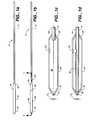
- FIG. 1 aillustrates a first exemplary embodiment of a control tip in accordance with the present invention
- FIG. 1 billustrates a second exemplary embodiment of a control tip in accordance with the present invention
- FIG. 1 cillustrates an enlarged cross-sectional view of a third exemplary embodiment of a control tip in accordance with the present invention, taken at line 1 — 1 ;
- FIG. 1 dillustrates an enlarged cross-sectional view of a third exemplary embodiment of a control tip in accordance with the present invention, taken at line 1 — 1 ;
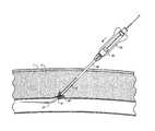
- FIG. 2schematically illustrates portions of a system in accordance with the present invention positioned in a blood vessel of a patient
- FIG. 3 aillustrates a side elevational view of portions of a first exemplary system in accordance with the present invention
- FIG. 3 billustrates an enlarged cross-sectional view of a portion of the exemplary embodiment of a pusher illustrated in FIG. 3 a in accordance with the present invention
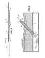
- FIG. 4schematically illustrates portions of the first embodiment, illustrated in FIG. 3 a , positioned in a blood vessel of a patient;
- FIG. 5illustrates a side elevational view of portions of a second embodiment of a system in accordance with the present invention
- FIG. 6schematically illustrates portions of the second embodiment, illustrated in FIG. 5 , positioned in a blood vessel of a patient;
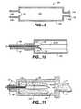
- FIG. 7illustrates a side elevational view of a system in accordance with the present invention.
- FIGS. 8 a - 8 fillustrate steps of an exemplary method in accordance with the present invention
- FIG. 9illustrates a cross-sectional view of a pledget hydration chamber in accordance with an exemplary embodiment of the present invention.
- FIG. 10illustrates the chamber of FIG. 9 with portions of a device of FIG. 7 ;
- FIGS. 11-13illustrate exemplary steps of hydrating, preparing, and positioning a pledget into a delivery device in accordance with an exemplary embodiment of the present invention
- FIG. 14illustrates a cross-sectional view of yet another embodiment of a control tip device in accordance with the present invention.
- FIG. 15illustrates a cross-sectional view of yet another embodiment of portions of a control tip device in accordance with the present invention.
- FIG. 16illustrates a cross-sectional view of yet another embodiment of portions of a control tip device in accordance with the present invention
- FIG. 17illustrates a cross-sectional view of yet another embodiment in accordance with the present invention.
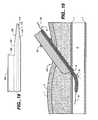
- FIG. 18illustrates a cross-sectional view of yet another embodiment in accordance with the present invention.
- FIG. 19diagrammatically illustrates a cross-sectional view of yet another embodiment in accordance with the present invention in one preferred use
- FIG. 20diagrammatically illustrates a cross-sectional view of yet another embodiment in accordance with the present invention in one preferred use
- FIG. 21diagrammatically illustrates a cross-sectional view of yet another embodiment in accordance with the present invention in one preferred use
- FIG. 22diagrammatically illustrates a cross-sectional view of yet another embodiment in accordance with the present invention in one preferred use
- FIGS. 23 a and 23 billustrate views of a tube component useful in yet another embodiment of the present invention
- FIGS. 24 a - 24 cillustrate top plan, side elevational, and top proximal right hand side perspective views, respectively, of yet another embodiment of a handle in accordance with the present invention
- FIGS. 25 a - 25 dillustrate several views of another embodiment of a pledget pusher in accordance with the present invention.
- FIGS. 26 a - 26 cillustrate perspective views, with portions broken away, of a hydration and loading device in accordance with the present invention
- FIGS. 27 a - 27 cillustrate perspective views, with portions broken away, of a handle, proximal hub of a control tip, and proximal hub of a pledget pusher in accordance with the present invention
- FIGS. 28 a - 28 cillustrate a collar in accordance with the present invention
- FIGS. 29 a - 29 cillustrate several steps in an exemplary method in accordance with the present invention.
- FIGS. 30-32illustrate three embodiments of a bleed-back control device in accordance with the present invention.
- “pledget”means a piece of sponge formed into a generally elongated shape having a size which allows delivery in a hydrated state through a delivery cannula or introducer to a site of a puncture in a blood vessel.
- “Sponge”means a biocompatible material which is capable of being hydrated and is resiliently compressible in a hydrated state.
- the spongeis non-immunogenic and may be absorbable or non-absorbable.
- “Absorbable sponge”means sponge which, when implanted within a human or other mammalian body, is absorbed or resorbed by the body.
- “Hydrate”means to partially or fully saturate with a fluid, such as saline, water, contrast agent, thrombin, therapeutic agents, or the like.
- FIG. 1 aillustrates a puncture control tip 10 in accordance with a first embodiment of the present invention.
- the puncture control tip 10includes a tubular, hollow puncture control tip shaft 14 which functions as a flash tube, as described in greater detail below.
- the shaft 14includes a lumen 34 (see FIG. 1 c , for example) which extends longitudinally between proximal and distal ends.
- lumen 34can optionally be coated or otherwise provided with an interior surface which inhibits blood coagulation.
- the lumen 34can be coated with material including heparin (e.g., heparinized), tPa, or other functionally similar materials or compounds which inhibit or prevent blood from clotting or otherwise coagulating in the lumen 34 .
- heparine.g., heparinized
- tPatPa
- the puncture control tip 10includes, at its distal end, a hollow puncture control head 16 mounted or otherwise secured to distal portions of the shaft 14 .
- the head 16includes a distal tapered portion 18 , a proximal tapered portion 20 , and a center portion 22 between the distal and proximal portions which preferably has a constant outer diameter. Both of the portions 18 and 20 can alternatively be a step, rounded shoulder, or the like.
- the interior of head 16is open to the exterior of the head at the distal portion 18 (see, e.g., FIGS. 1 c and 1 d ).
- FIG. 1 billustrates another embodiment of a puncture control tip 12 in accordance with the present invention.
- the control tip 12is similar to control tip 10 , but includes a puncture control tip head 24 which includes a hole 26 which communicates the exterior of the head with the interior thereof and functions as a flash hole or vent for the control tip.
- a hole 26 ′can be included in addition to, and preferably instead of, hole 26 .
- Hole 26 ′is formed in the shaft 14 proximal of and proximate to the proximal portion 20 , and communicates the interior lumen of the shaft with the exterior of the shaft.
- Shaft 14includes lumen 34 which fluidly communicates the interior 30 of heads 16 , 24 with a proximal end of the shaft.
- the lumen 34has an inner diameter selected to be larger than the external diameter of a guidewire, preferably an exchange wire 28 , used therewith (see FIG. 2 ).
- a plurality of holes 26can be formed in the control head, circumferentially spaced and at the same longitudinal location as hole 26 .
- head 16 , 24can be relatively thin walled such that the internal dimensions of the interior cavity 30 is larger in center portion 22 than in the distal 18 and proximal 20 portions of the head.
- the distal portion 18 of head 16 , 24includes a distal port 32 having an internal opening diameter D 1 also selected to be larger, and preferably only slightly larger, than the external diameter of a wire 28 used with the control tip 10 , 12 .
- one aspect of the present inventionis that by selecting the external diameter of wire 28 and the inner diameter of port 32 to be only slightly different, blood flow into interior 30 of head 16 , 24 is greatly restricted, thus allowing the hole 26 to be the sole entrance into the control tip for blood to flow up shaft 14 to indicate that the control tip head has been located in a blood vessel.
- the head 16 , 24can be formed with a thick wall, such that the interior chamber 30 is the same size as port 32 .
- control tipis formed of a flexible, biocompatible material such as a thermoplastic.
- material out of which the control tip is formedhas a Shore hardness between about 90A-82D, preferably between about 98A-74D, more preferably about 64D.
- FIG. 2some functions of control tips in accordance with the present invention can be better appreciated.
- the practitionerwill oftentimes want to seal the access point to the patient's vasculature.
- a guidewire, exchange wire, or guide catheterremains in the patient's blood vessel 5 at the end of the procedure.
- the indwelling deviceextends through the epidermis layer 1 , through the subcutaneous layers 3 , and enters the vessel wall 7 at a puncture site 9 .
- a control tip 12(as illustrated in FIG. 2 , although control tips 10 can also be used) is advanced either through an indwelling guide catheter, or over an indwelling wire 28 , until blood B enters hole 26 .
- the blood Bflows into interior 30 of the control head 24 , through lumen 34 and around the wire 28 , and exits the shaft 14 at its proximal end.
- This flash of blood at the proximal end of shaft 14gives the practitioner a visual indication that the control tip is seated in the puncture site 9 , while the placement of the hole 26 distal of the proximal portion 20 assists in maintaining the puncture site closed during the procedure.
- vent tube 14can optionally be formed to have a flexibility which changes along its length, e.g., is more flexible at distal portions than at proximal portions. While a gradual distal increase in flexibility is preferred, the change can be more abrupt, such as by forming the vent tube 14 of two distinct tubes of different flexibilities, although this later embodiment is less preferred.
- FIG. 3 aillustrates an embodiment of a depth marker 36 mounted over a control tip 12 in accordance with the present invention.
- Marker 36is a hollow, tubular member preferably shorter than the control tip 12 .
- Marker 36optionally further includes a collar 38 slidable along the outer surface of the marker.
- the collar 38is preferably elastic such that it will engage the exterior of the marker 36 to hold its position on the marker, yet be movable along the marker upon the application of a small force to slide the collar along the marker.
- collar 38can be used as a depth indicator, as described in greater detail below.
- the marker 36includes a proximal end 40 , a distal end 42 , and an interior lumen 44 extending longitudinally between the proximal and distal ends.
- the proximal and distal ends of the marker 36preferably include a seal with the shaft 14 of the control tip 12 .
- the seal between the shaft 14 and the marker 36can be formed in any suitable way that provides a fluid seal between the marker and the shaft.
- the proximal and distal sealscan be formed by forming the marker with a reduced inner diameter at (at least) the proximal and distal ends of the marker, or by including dynamic sealing members, such as O-rings or septa.
- at least the distalmost portions of distal end 42is slightly rounded to prevent trauma to the vascular tissues with which it comes into contact.
- Marker 36is preferably attached to control tip 12 , or less preferably, positioned on the control tip 12 so that it is difficult to slide them longitudinally relative to each other.
- the distal end 42is spaced from the elongated central portion 22 of the control head by a distance X, described in greater detail below.
- the control tip and the markercan be interconnected using a releasable proximal connection, e.g. a Touhy-Borst connector (for which the marker would include cross-drilled holes or the like for blood flash), ultrasonic welding, gluing, etc.
- FIG. 3 billustrates an enlarged cross-sectional view of a distal end of a marker 36 or 46 in accordance with the present invention.
- the markerincludes an interior lumen 44 which terminates at the distal end 52 of the marker with a countersunk tapered distal port.
- the taper of the distal port relative to longitudinal axis Ais selected to be very similar to that of the proximal tapered portion 20 of head 16 , 24 .
- This aspect of the present inventionpermits the wall of the marker 36 , 46 which forms the port, together with the proximal tapered portion 20 , to function as a valve in a manner similar to a needle valve.
- FIG. 4illustrates a control tip 12 used together with a depth marker 36 to control a puncture site 9 .
- the control tip 12has been located in the puncture site 9 , as shown by the blood flash B out the proximal end of flash tube 14 , with the marker 36 on the shaft 14 the practitioner feels the additional resistance offered by the vessel wall 7 to further advancement of the marker upon distal advancement of the control tip/marker assembly.
- the distal end 42 of the marker 36forms a seal with the shaft 14 , the distal end 42 can then be used to control the flow of blood out of the puncture site 9 , and the control head 24 is pushed slightly distally into the blood vessel 5 .
- Collar 38can be positioned against the epidermis 1 when the distal end 42 is at the puncture site 9 , which permits the collar 38 to mark the distance between the distal end of the marker 36 and the outer surface of the epidermis, thus functioning as a depth indicator of the puncture site.
- FIG. 5illustrates a control tip 10 with head 16 and a marker 46 mounted thereover.
- Marker 46is similar to marker 36 , described above, but does not include seals at its proximal 50 and distal 52 ends.
- a lumen 48extends longitudinally through the marker 46 between the proximal and distal ends and forms an annular space or lumen 54 between the flash tube or shaft 14 and the marker 46 .
- distal end 52is tapered as illustrated in FIG. 3 b.
- Marker 46is affixed to control tip 10 in a fashion similar to marker 36 and control tip 12 , described above.
- FIG. 6illustrates a marker 46 used in accordance with one aspect of the present invention with a control tip 10 . While control tip 12 can also be used, the function of flash hole or holes 26 is assumed by the combination of proximal tapered portion 20 of head 16 and the distal end 52 of marker 46 , optionally further including a tapered countersunk port therein. In a manner similar to that described above with reference to FIG. 4 , the marker 46 can be used to control puncture site 9 . By moving the assembly of the control tip 10 and the marker 46 longitudinally, the distal end 52 of the marker 46 and the proximal tapered portion 20 of the head 16 can be used to throttle the flow of blood into the annular lumen 54 in a manner similar to a needle valve.
- the flow cross-sectional areais made smaller, thereby reducing the flow of blood into the lumen 54 , and pushing the assembly distally increases the flow area, increasing the flow of blood.
- blood flash Bcan be observed out of the proximal end of the marker 46 , indicating that the marker is in fluid communication with the blood vessel 5 .
- wire 28 and port 32as described above, permit little or no blood to flow into lumen 34 of the shaft 14 , the blood flash B at proximal end 50 can be a reliable indicator that the blood vessel has been accessed.
- the distal end of the depth markerhas significant radial or lateral clearance from the control tip shaft, so that the two elements will move laterally relative to each other near the marker's distal end, which promotes tactile feedback to the practitioner when the control tip enters the blood vessel.
- FIG. 7illustrates a side elevational view of a system in accordance with the present invention.
- the systemgenerally includes a control tip 10 or 12 , a pledget pusher 37 , a delivery cannula 56 , a pledget 90 , and a proximal handle 62 .
- pledget 90is positioned in a lumen 58 in delivery cannula 56 and around shaft 14 of control tip 12 .
- Pusher 37is also positioned in lumen 58 , and has a length such that, when the pusher is in a retracted, proximal position illustrated in FIG. 7 , the distal end 42 , 52 of the pusher is proximal of the distal end of the delivery cannula 56 .
- a pledget 90is positioned in the distal portion of the lumen 58 distal of the distal end of the pusher 37 so that the pusher can push the pledget distally out of the delivery cannula.
- Pledget pusher 37is structurally very similar to either pusher 36 or pusher 46 , but is not attached to the control tip 10 , 12 over which it longitudinally slides.
- the pledget 90is formed from a sheet of absorbable sponge material which has been cut into a rectangular shape and rolled to form a compact, substantially cylindrical, elongated pledget.
- absorbable sponge materialwhich is acceptable for use in the present invention is GelfoamTM, manufactured by the Pharmacia & Upjohn Company. GelfoamTM is a porous, pliable, cross-linked gelatin material and is available commercially in sheet form as pre-compressed or non-compressed sponge.
- the materialmay be provided preformed as a pledget 90 or may be cut with a punch, or a stencil, or template and knife and rolled to form a pledget.
- the pledget 90can be easily compressed to fit into a lumen having a smaller cross sectional area than the original cross sectional area of the pledget. Additionally, the kneading of the hydrated pledget 90 during delivery encourages air trapped within the GelfoamTM to be expelled and replaced with fluid, allowing rapid expansion upon delivery.
- a pledget 90 of a pre-compressed GelfoamTMis hydrated and kneaded (expelling air) during delivery, the pledget will have the absorption capacity to rapidly expand to many times (e.g., 3 or more times) its original dry volume upon delivery.
- the pledget 90 of the non-compressed GelfoamTMWhen a pledget 90 of the non-compressed GelfoamTM is hydrated and kneaded (expelling air) during delivery, the pledget will have the absorption capacity to rapidly expand to its original dry volume upon delivery. These properties make the GelfoamTM sponge material particularly useful for facilitating hemostasis of puncture sites by injection.
- the delivery cannula 56includes a proximal hub 60 .
- Hub 60includes mating structures to mate with corresponding mating structures formed in a distal hub 76 of handle 62 .
- the mating structures of hub 60 and hub 76can be luer fittings, screw threads, releasable bayonet fittings, and any other fitting which can releasably connect together hubs 60 , 76 so that the delivery cannula 56 and the handle 62 can be moved together when the structures are mated, and the delivery cannula and handle can be separated and moved independently when the structures are released.
- Pusher 37includes a proximal hub 78 which both limits the proximal and distal movement of the pusher, and provides an enlarged section at which a practitioner can grasp the pusher if necessary.
- Hub 78optionally further includes a proximal outwardly flared stop 80 which limits longitudinal motion of the pusher 37 relative to the handle 62 and other structures of the system, described in detail below. More particularly, stop 80 limits distal motion of the pusher 37 , because it has an outer dimension (e.g., diameter) larger than portions of hub 76 of handle 62 , and limits proximal motion because the stop is longitudinally aligned with portions of a motion limiting device 82 (described below) positioned proximal of the stop.
- a motion limiting device 82described below
- Handle 62generally provides a place for a practitioner to grasp and manipulate the control tip 12 , pusher 37 , and delivery cannula 56 together, while also permitting the practitioner to separately move these individual components. Therefore, while a particular embodiment of a handle in accordance with the present invention is illustrated in FIG. 7 , the present invention relates more generally to structures which performs these functions.
- Handle 62includes a first side 64 , a second side 66 , and an open interior space 68 .
- a practitioneris able to access the proximal portions of pusher 36 , 46 and control tip 12 in order to manipulate these elements.
- Each of the sides 64 , 66includes a wing 70 , 72 , respectively, which is optionally further provided to provide a bearing surface for a practitioner to pull the handle and any attached elements proximally.
- the proximal end of the handle 62includes an opening, slot, or the like 74 which receives a proximal motion limiting device 82 for the control tip 12 .
- device 82includes a proximal flange 84 which extends radially beyond the extent of opening 74 , and therefore limits distal motion of the device 82 as it slides in the opening 74 .
- the device 82also includes a central cylindrical portion 86 which longitudinally slides in opening 74 .
- a distal bumper 88 of device 82is also radially larger than opening 74 , and limits proximal motion of the device 82 relative to the handle 62 .
- the flash tube or shaft 14is secured to and preferably extends proximally through device 82 , as illustrated in FIG. 7 .
- the entire control tip 12is permitted to move longitudinally over a limited range delimited by the proximal flange 84 and the distal bumper 88 . Because the control tip 12 is therefore permitted to move longitudinally over only a limited range defined by device 82 , and handle 62 is attached to delivery cannula 56 via hubs 60 and 76 , the control tip is capable of moving longitudinally over only a limited range relative to the delivery cannula.
- the magnitude of range X(see FIGS.
- 3 a , 5 , and 8 Ais between about 0.025 inches (0.06 cm) and about 0.25 inches (0.6 cm), preferably between about 0.1 inches (0.25 cm) and about 0.2 inches (0.51 cm), and more preferably about 0.15 inches (0.38 cm).
- device 82can take forms different from those illustrated in FIG. 7 , while still performing the functions describe above.
- device 82 and handle 62can include other types of complementary surfaces, including mating threads, tabs and slots, and the like, within the scope of the present invention.
- opening 74can be formed open on one lateral side, so that device 82 can be snapped into the handle 62 in a direction into or out of the plane of view of FIG. 7 , thereby permitting assembly and disassembly of the handle with the other elements of the system.
- FIGS. 8 a - 8 fillustrate a system as illustrated in FIG. 7 used in accordance with an exemplary embodiment of the present invention.
- a wire 28is advanced into the patient's blood vessel 5 through a puncture site 9 in the vessel wall 7 .
- a control tip 12 , pusher 37 , delivery cannula 56 , handle 62 , and pledget 90are advanced together over the wire 28 , as illustrated in FIG. 8 a .
- the control tipis first advanced over the wire and into the blood vessel, and thereafter the delivery cannula, handle, pusher, and pledget are advanced over the control tip.
- the control head 24passes through the puncture site 9 . Because the vessel wall presents more resistance to the control head than the subcutaneous tissues 3 , the practitioner can feel when the control head has reached the outer portions of the puncture site 9 . The practitioner then advances the control head further into the patient and into the blood vessel 5 .
- blood Bflashes out the proximal end of flash tube 14 , as described above, indicating to the practitioner that entry to the blood vessel has been made. Because blood may have previously been present in lumen 34 of shaft 14 , and therefore potentially has already clotted or coagulated, blocking the lumen 34 , it is preferable that lumen 34 be coated with a blood anticoagulant, as described above. Another tactile indication to the practitioner that entry to the blood vessel 5 has been made is provided by the distance or gap X between the proximal end of the control head 24 and the distal end of the delivery cannula 56 .
- the practitionercan feel that the system is more easily moved laterally when the control head 24 is in the position illustrated in FIG. 8 a . Conversely, when the practitioner does not feel this reduced resistance to lateral movement of the system, the practitioner has an indication that the blood vessel 5 has not been properly accessed.
- FIG. 8 billustrates a stage in the exemplary method later than that illustrated in FIG. 8 a .
- FIG. 8 cillustrates a stage in the exemplary method later than that illustrated in FIG. 8 b .
- the device 82(described above) is pulled proximally relative to the handle 62 while the remaining elements of the system are held stationary.
- the control tip 12including the control head 24 , is retracted proximally and engages the inner surface of the vessel wall at the puncture site 9 .
- both the interior and exterior surfaces of the vessel wall 7are engaged by portions of the system, which controls blood flow out of the puncture site.
- the present inventionis also advantageous because it can be used to prevent introduction of all or portions of a pledget into the bloodstream of a patient, which could otherwise initiate a clotting sequence in the blood vessel, with predictably hazardous consequences to the patient.
- FIG. 8 dillustrates a stage in the exemplary method later than that illustrated in FIG. 8 c .
- the handle 62 , delivery cannula 56 , and control tip 12have been retracted proximally, while holding stationary the pusher 37 , such as by pulling proximally on the distal portions of bumper 88 while engaging the proximal portions of stop 80 to prevent its longitudinal motion.
- Proximal retraction of the delivery cannula 56 relative to the pusher 37causes distal portions of the pledget 90 to be exposed, while at the same time the pusher does not move and is left positioned at the exterior surface of the blood vessel 5 at the puncture site 9 .
- proximal portions of the control head 24are drawn through the distal portions of the pledget 90 . It is preferable that the handle 62 , delivery cannula 56 , and control tip 12 are moved only part of the distance necessary to completely expose the pledget 90 and for stop 80 to engage portions of hub 76 , as illustrated in FIG. 8 d , so that the pledget can be expressed and compressed, as described below with reference to FIG. 8 e.
- FIG. 8 eillustrates a stage in the exemplary method later than that illustrated in FIG. 8 d .
- the pusher 37While holding handle 62 stationary relative to the patient, the pusher 37 is advanced distally down the control tip 12 , which expels or pushes the remainder of the pledget 90 out of the lumen 58 and simultaneously compresses the pledget against the external surface of the blood vessel wall 7 at the puncture site 9 .
- the control head 24is positioned in the puncture site 9 , and therefore at least inhibits, and preferably prevents, the pledget 90 from being pushed into the blood vessel 5 .
- the puncture site 9is controlled throughout the steps of positioning the pledget 90 adjacent to the exterior of the puncture site and both inhibits bleeding and inhibits the introduction of material, including the pledget 90 as well as tissue fragments, into the blood vessel.
- FIG. 8 fillustrates a stage in the exemplary method later than that illustrated in FIG. 8 e .
- the handle 62is released from its connection with the delivery cannula 56 by releasing the connection between hub 76 and hub 60 .
- the handleis then retracted proximally, carrying with it the control tip 12 and the pusher 37 .
- the delivery cannula 56is preferably held stationary in the patient during this retraction, so that the delivery catheter can hold the pledget 90 in place.
- the siteis compressed by the pledget 90 , which inhibits bleeding and promotes closure of the puncture site.
- the control tip 12As the control tip 12 is further retracted, the control head 24 is drawn through the pledget, while the delivery cannula inhibits the pledget from following the control tip back up into the delivery cannula.
- the handle, pusher, and control tipare then completely removed.
- the delivery cannulais removed, preferably slowly and with the application of localized compression to the epidermis above the puncture site, leaving the pledget 90 in place to promote healing of the puncture site 9 and inhibit blood flow from the blood vessel.
- FIG. 8 fAlso illustrated in FIG. 8 f is an exemplary embodiment of the mating structures of hubs 60 and 76 which releasably hold together the handle 62 and the delivery cannula 56 .
- hub 60includes a mating structure 92 , e.g., a tubular extension 94 including a tab 96 extending radially therefrom.
- Hub 76includes an internally threaded collar 96 which receives the extension 94 therein and secures the two elements together.
- FIG. 9illustrates an exemplary embodiment of a pledget loading device 100 useful for preparing a pledget 90 and loading the pledget into a delivery cannula.
- the pledget loading device 100includes a body 102 having an interior chamber 104 .
- a tubular receiving element 106extends distally from the distal end of the body, and includes a lumen 116 therein communicating the interior chamber 104 with the exterior of the body.
- a fluid coupling 108extends proximally from the end of the body opposite the element 106 , and includes a flange, tab, or the like 112 and an internal lumen 114 which communicates the interior chamber 104 with the exterior of the body.
- the flange 112is structured to releasably mate with a corresponding structure on a high pressure fluid delivery device, e.g., a syringe with a luer fitting.
- the body 102also includes a stop 110 positioned in the lumen 116 which prevents a delivery cannula of a size greater than the internal dimension of the stop from entering into the chamber 104 .
- FIG. 10illustrates the pledget loading device 100 with a delivery cannula 56 , pusher 37 , and a control tip 12 inserted into the tubular receiving element 106 .
- stop 110is sized so that the delivery cannula 56 is prevented from entering into the chamber 104 , and preferably forms a fluid seal with the stop 110 , the inner surface of the element 106 , or both.
- the pusher 37 and the control tip 12extend into the chamber 104 .
- the combination of the tapered countersunk distal end 52 of the pusher and the tapered proximal portion 20 of the control head 16 , 24form a fluid control member 118 which operates in a manner similar to a needle valve. The operation of fluid control member 118 will be described in greater detail below.
- a cylindrical pledget 90has been inserted into the chamber 104 .
- the pledgetcan be placed in the chamber 104 before or after the control head 16 , 24 is positioned in the chamber.
- a source of hydration fluidsuch as a syringe (not illustrated), is coupled to fluid coupling 108 , and hydration fluid F is injected into the chamber 104 .
- Air in the chamber 104is allowed to escape through fluid control member 118 , while the pledget 90 is retained in the chamber and hydrated.
- the pusher 37is retracted into the lumen 58 of the delivery cannula 56 , in effect opening the fluid control member 118 .
- Air and hydration fluidare then allowed to flow past the stop 110 , through the lumen 58 , through the lumen 39 of pusher 37 , and out of the system.
- the further introduction of high pressure fluid into chamber 104forces the hydrated pledget 90 past the stop 110 and into the portion of lumen 58 not occupied by the pusher 37 , while hydration fluid continues to flow out the lumen 39 .
- the hydrated pledget 90is loaded into the end of the delivery cannula 56 .
- FIG. 14illustrates yet another embodiment of a control head in accordance with the present invention.
- a constant outer diameter guidewire 120is slidingly received in the tapered distal portion 20 of a control tip 24 .
- the guidewire 120 and the tapered portion 20are nearly the same size, so that there is little or no blood flow into the interior 30 of the control head 24 past the guidewire.
- Such an arrangementhelps assure that any blood flow into the flash tube 14 (see FIGS. 1 a - 1 d ) enters the control head 24 through the hole 26 .
- FIG. 15illustrates yet another embodiment in accordance with the present invention.
- the proximal end of shaft 14is fitted with a removable insertion tip 130 so that the proximal end of the shaft, with the tip 130 mounted in the shaft as illustrated in FIG. 15 , can be backloaded through a pledget (not illustrated) held within a distal end of a delivery cannula (not illustrated).
- the insertion tipin the embodiment illustrated in FIG. 15 , includes a shank 132 and a head 134 attached to the shank.
- the shankhas an outer dimension (e.g., diameter) sized to be received in the lumen 34 of the shaft 14 , and can be large enough to form an interference or press fit with the shaft.
- the shank 132 and the head 134meet at a shoulder 136 which abuts the proximalmost end of the shaft 14 .
- the headpreferably includes a pointed or otherwise tapered tip 138 which assists in moving portions of the pledget radially outward when the shaft and insertion tip 134 are pushed longitudinally through the pledget.
- FIG. 16illustrates yet another embodiment in accordance with the present invention.
- a stylet 150is inserted through a control tip 10 or 12 and assists in inserting the control tip through a pledget (not illustrated) positioned inside a delivery cannula (not illustrated).
- the stylet 150includes a head 152 and a shaft 154 connected to and extending from the head.
- the shaft 154is sized to slide through the control tip and shaft 14 .
- the head 152is enlarged to facilitate pushing on the head to push the proximal end of the shaft 14 through a pledget; the shaft 154 extends from the proximal end of the shaft to assist is radially parting the material of the pledget.
- FIG. 17illustrates yet another embodiment in accordance with the present invention, in which a delivery cannula 160 includes a control tip 168 integral with the delivery cannula.
- the delivery cannula 160has a tubular wall 162 which extends longitudinally between a proximal end 162 and a distal end 164 , which distal end is preferably rounded to ease its insertion through subcutaneous tissues and limit trauma to the vascular wall when it is pressed against it.
- a lumen 166extends through the delivery cannula 160 between the proximal end 162 and the distal end 164 , and is sized in a manner similar to the other embodiments described herein to receive a pledget, pledget pusher, and/or wire.
- the control tip 168extends longitudinally between a proximal end 170 and a distal end 172 radially offset from the center longitudinal axis of the lumen 166 .
- the control tip 168includes a longitudinally extending lumen 174 and a vent port or hole 176 similar to hole or holes 26 .
- the distal end 172is preferably tapered, and preferably has an inner diameter which tapers distally, as at 178 , to form a dynamic seal with a wire (not illustrated) over which the control tip 168 is inserted. As illustrated in FIG.
- the external taper 180 of the distal end of the control tip 168can extend proximally toward the delivery cannula 160 , and the vent hole 176 is preferably formed in this tapered section. Less preferably, however, the vent hole 176 can be formed in the untapered portion 182 within the scope of the present invention.
- FIG. 19illustrates yet another embodiment in accordance with the present invention.
- a depth marker 190is similar to the delivery cannula 160 having the integral control tip 168 , but does not include a lumen 166 .
- a collar 38is positioned on the outer surface of the depth marker, and permits the user to record the depth of the blood vessel 5 relative to the outer surface of the epidermis 1 .
- the depth marker 190is otherwise used in the same manner as the other embodiments of depth markers described herein.
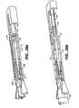
- FIG. 20illustrates yet another embodiment in accordance with the present invention.
- a biaxial delivery cannula 200includes a lumen 202 sized to receive a pledget 90 and a pledget pusher or piston 204 which extends proximally out of the delivery cannula 200 .
- the delivery cannula 200also includes an integral control tip 206 having a longitudinally extending through lumen 210 extending from the control head 208 proximally to the proximal end of the delivery cannula in a manner similar to other embodiments described herein.
- the lumen 210is sized to slidingly receive the wire 28 , and preferably forms a seal with the wire 28 as also described elsewhere herein.
- the delivery cannula 200further includes a vent lumen 212 laterally offset from the lumen 202 and the lumen 210 , and preferably between the lumenae 202 , 210 .
- the vent lumen 212permits blood to flash to the proximal end of the delivery cannula 200 to give a visual indication of when control of the puncture site 9 is made and lost.
- FIG. 21illustrates yet another embodiment in accordance with the present invention.
- the embodiment illustrated in FIG. 21is similar is some respects to the embodiment illustrated in FIG. 7.
- a delivery cannula 56 , control tip 10 or 12 , pledget 90 , pusher 37 , and wire 28are similar or the same as described above, and are used in combination with a coaxial vent tube 220 which extends longitudinally through the pusher 37 and the pledget 90 .
- the vent tube 220includes a longitudinally extending lumen 222 which is sized to receive the control tip 10 , 12 therein with an annular clearance to permit blood to flash proximally through the vent tube 220 .
- the shaft 14 of the control tip 10 , 12can be formed without a lumen 34 , and can be dimensioned with a smaller outer diameter to increase the annular clearance between the shaft and the vent tube 220 .
- the shaft 14preferably maintains its relative flexibility to permit the tactile feedback previously described herein.
- the embodiment illustrated in FIG. 21is used in a manner otherwise similar to those previously described herein.
- FIG. 22illustrates yet another embodiment in accordance with the present invention.
- a vent tube 230can be used with a control tip 10 , 12 SO that the vent tube and control tip are advanced laterally next to each other to the puncture site 9 .
- the vent tube 230permits blood to flash proximally to give a visual indication of when control of the puncture site 9 is made and lost by the control head of the control tip.
- FIGS. 23 a and 23 billustrate a fluid handling tube 300 useful in accordance with yet another embodiment of the present invention, one particular use of which will be described in greater detail below.
- the tube 300includes a cylindrical sidewall 302 extending between a proximal end 306 and a distal end 304 .
- a hollow interior 308is delimited by the sidewall 302 .
- the proximal end 306preferably includes an enlarged portion 310 which assists the tube 300 in conducting fluid therethrough.
- At least one, and preferably numerous fluid ports 312are formed through the sidewall 302 adjacent to the distal end 306 .
- FIGS. 24 a - 24 cillustrate several views of a handle 400 according to yet another embodiment of the present invention.
- Handle 400is similar in many respects to handle 62 .
- Handle 400includes a top portion 402 and a bottom portion 404 which together form a generally rectangular housing.
- the handle 400includes a proximal end 406 and a distal end 408 .
- a releasable hollow locking hub 410extends distally from the distal end 408 , and is structured to releasably mate with a proximal hub of a delivery cannula, similar to cannula 56 and described in greater detail below.
- a longitudinally extending slot 412is formed in each of the top 402 and bottom 404 , each slot 412 including a proximal enlarged portion 414 and a proximal narrow portion 416 . Adjacent to and on at least one, and preferably both sides of both narrow portions 416 are formed ramps 418 which extend outwardly from the outer surfaces of the top 402 and bottom 404 a distance sufficient to interfere with the movement of portions of a pledget pusher handle, described in greater detail below.
- the ramps 418are also formed at the distal end of the ramps 418 .
- the lips 422extend outwardly from the top 402 and bottom 404 a distance sufficient to enable portions of a pledget pusher handle to cam over the lips and releasably lock therewith, as described in greater detail below.
- the top 402 and bottom 404can also optionally be further provided with raised ridges 420 adjacent the proximal end 406 which aid the user of the handle in manipulating it.
- the handle 400includes a proximal opening 424 .
- the proximal opening 424is U-shaped with an enlarged, more open upper portion 426 .
- the enlarged portion 426acts as a slot to permit portions of a control tip proximal hub, similar in some respects to hub 82 and described in greater detail below, to pass out of the handle 400 and permitting the handle and the control tip to move relative to each other.
- the proximal opening 424also includes a lower slot 430 which extends distally into the handle 400 , and a proximally extending stud 428 .
- Lower slot 430cooperates with a portion of a proximal handle of a control tip, and stud 428 cooperates with other portions of the proximal handle of the control tip, described in greater detail below.
- FIGS. 25 a - 25 dillustrate several views of a pledget pusher 500 according to yet another embodiment of the present invention.
- Pusher 500is similar in some respects to pusher 37 described above.
- Pusher 500includes a proximal end 502 , a distal end 504 , and a hollow tubular member 506 extending between the ends.
- the distal end 504includes an enlarged portion 508 .
- the enlarged portion 508can have a trumpet, flared, or tulip-like shape.
- the enlarged portion 508assists in both preparing a pledget for implantation as well as pushing the pledget during the processes of the present invention.
- the enlarged portion 508is sized so that the pledget pusher 500 has little or no radial space between the enlarged portion and the inner surface of a delivery cannula, such as cannula 56 , when installed therein.
- the proximal end 502 of the pledget pusher 500includes a proximal hub 514 to which are attached several additional elements. At least one, and preferably two finger engaging portions 510 , 512 are cantilevered to the proximal hub 514 through attachment posts 518 , 518 , respectively; when both portions 510 , 512 are provided, they are preferably formed on diametrically opposite lateral sides of the pusher 500 . As illustrated in the drawing figures, portions of the finger engaging portions 510 , 512 extend distally of the attachment posts 516 , 518 and include distal latches 520 , 522 which extend radially inward.
- the distal latchesare sized and positioned so that, when the pusher 500 is positioned relative to the handle 400 as described herein, the latches cam over the ramps 418 when pushed distally, and also are sized and positioned to cam over and latch the lips 422 to releasably hold together the pusher 500 and the handle 400 .
- the pusher 500also includes at least one, and preferably two proximal latches 524 , 526 which extend proximally from the proximal hub 514 .
- the latches 524 , 526extend radially inward, and are sized and positioned to engage with and releasably lock with corresponding portions on the proximal hub of a control tip, as described in greater detail below.
- both latches 524 , 526are provided, they are preferably formed on diametrically opposite lateral sides of the pusher 500 . While FIGS.
- the pusher 500also optionally further includes one or a pair of laterally extending movement guide studs 528 , 530 .
- the studs 528 , 530when provided, are attached to the proximal hub 524 and are sized to loosely engage the inner surfaces of the handle 400 to assist in the pusher 500 to better track as it moves longitudinally.
- FIGS. 26 a - 26 cillustrate partial cross-sectional, perspective views of a pledget hydration and loading device 600 used to both hydrate a pledget 90 and load the hydrated pledget into a delivery cannula 56 in accordance with the present invention.
- Device 600is similar in function to device 100 , described above.
- Device 600preferably includes the fluid handling tube 300 mounted therein, with the distal end 304 extending around the control tip 24 and the hole 26 . In this position, the fluid handling tube 300 inhibits, and preferably prevents, hydration fluid from entering the flashback lumen of the control tip through the hole 26 .
- the holes 312are provided so that any hydration fluid which flows through the interior of the tube 300 can flow through the holes 312 and around the outside of the tube to hydrate and move the pledget 90 .
- the enlarged portion 508is positioned at least at the distal end of the delivery cannula 56 , and preferably distal thereto. The enlarged portion 508 thus inhibits, and preferably prevents, portions of the pledget 90 from getting behind the distal end 504 of the pledget pusher 500 when the pledget is loaded into the delivery cannula 56 .
- FIG. 26 billustrates a stage in a process of hydration and loading of the pledget 90 in the pusher 500 later than that illustrated in FIG. 26 a .
- Hydration fluid from source 602such as a syringe, flows through the holes 312 , around the outside of the tube 300 , and pushes the pledget 90 into the lumen of the delivery cannula 56 .
- FIG. 26 cillustrates a stage in a process of hydration and loading of the pledget 90 in the pusher 500 later than that illustrated in FIG. 26 b . Hydration fluid has pushed the pledget 90 entirely into the delivery cannula 56 , with the enlarged portion 508 of the pusher 500 proximal of the pledget.
- FIGS. 27 a - 27 cillustrate perspective views, with portions broken away to aid in an understanding of the invention, of proximal portions of the pusher 300 , handle 400 , and a proximal hub 700 of a control tip 14 assembled together in accordance with the present invention.
- the distal portions of the control tipare similar to the distal portions of control tip 14 , described above.
- the pledget pusher 500is positioned adjacent to the distal hub 410 of the handle 400 .
- the proximal hub 700includes at least one, and preferably a pair of laterally extending wings 702 , 704 , which assist the user of the devices in manipulating the control tip 14 .
- a proximal cylinder 706extends distally from the wings 702 , 702 , and extends through the proximal opening 424 of the handle 400 .
- the enlarged portion 426acts as an upper open end 426 and the lower slot 430 are also illustrated in FIG. 27 a .
- a first laterally extending key 708is formed at a distal end of the cylinder 706
- a second laterally extending flange 710is formed at least partially along the length of the cylinder and diametrically opposite the first key 708 . Because of the perspective at which FIG. 27 a is illustrated, the flange 710 is behind the cylinder 706 .
- a distal cylinder 716extends distally from the proximal cylinder 706 , and preferably has a smaller outer diameter.
- At least one, and preferably a pair of ramp latches 712 , 714extend laterally from the exterior surface of the cylinder 716 , with the higher portions of the ramps being at the ramps' proximal ends.
- the ramp latches 712 , 714are sized and positioned so that when the pledget pusher 500 is moved proximally, the proximal latches 524 , 526 cam over the top surfaces of the ramp latches and releasably lock to the proximal faces of the ramp latches. This locked position is illustrated in FIG. 27 b.
- the first key 708 and the second flange 710are diametrically oppositely arranged, and the ramp latches 712 , 714 are also diametrically oppositely arranged.
- Another aspect of the present inventionis that the key 708 /flange 710 pair are offset along the circumferences of the cylinders 706 , 716 from the ramp latches 714 / 712 pair. While in the embodiment illustrated in FIGS. 27 a - 27 c, this offset is approximately the maximum 90 degrees, this angular offset can, within the scope of the present invention, be less than 90 degrees. This angular offset is useful in the present invention to restrict the relative motions of several of the elements described herein.
- rotational motion of the control tip 14 and its proximal hub 700 relative to the handle 400 and the pledget pusher 500unlocks the pusher from the control tip, and aligns the key 708 with the opening 424 , and aligns the flange 710 with the slot 430 , thus permitting the proximal hub 700 to be moved proximally relative to the handle 400 .
- FIG. 27 billustrates the pledget pusher 500 after having been moved proximally so that the proximal latches 524 , 526 have cammed over the ramp latches 712 , 714 , securing the pusher to the control tip 14 .
- the finger engaging portions 510 , 512 of the pusher 500extend through the slots 412 of the handle 400 , and therefore the pusher cannot rotate relative to the handle.
- the proximal hub 700can rotate relative to the handle 400 , and that relative rotation is also restricted, as described below.
- FIG. 27 cillustrates relative positions of the proximal hub 700 , handle 400 , and pusher 500 after the hub 700 has been rotated clockwise (as seen from the proximal end of the assembly) and retracted proximally.
- the ramp latches 712 , 714have been rotated away from the proximal latches 520 , 522 , which permits the proximal hub 700 to move independently off the pledget pusher.
- This rotation of the proximal hub 700is also relative to the handle 400 , and results in the alignment of the key 708 with the open upper end 426 , and the alignment of the flange 710 with the slot 430 .
- the proximal hub 700includes a set of structures on distally directed portions of the wings 702 , 704 , which cooperate with the stud 428 on the proximal end of the handle to restrict the motion of the proximal hub 700 relative to the handle 400 to a single direction of rotation.
- a first notch 720is separated from an elongated second notch 722 by a cam 724 .
- the first notch 720is in part defined by a face 728
- the second notchis in part defined by a face 726 .
- the second notch 722is axially aligned with the stud 428 (which, because of the perspective of the illustration, is obscured) when the flange 710 is in the slot 430 .
- the stud 428is positioned between the cam 724 and the face 720 , i.e., in the first notch 720 . In the orientations of FIGS.
- the face 728prevents the proximal hub 700 from being rotated in the direction of arrow 732 , while the stud 428 can, with the exertion of additional force, move past the cam 724 in the direction of arrow 730 and into the second notch 722 .
- the face 726restricts further rotational motion of the proximal hub 700 relative to the handle 400 because the stud hits the face 726 .
- the relative movement of the proximal hub 700 and the handle 400are thus restricted by the stud 428 , notches 720 , 722 , key 708 , flange 710 , open end 426 , and slot 430 .
- FIGS. 28 a - 28 cillustrate a collar 38 positioned on the outer surface of the delivery cannula 56 , as described above, in combination with several alternative embodiments of the present invention.
- the collar 38assists the user of the devices of the present invention in correctly positioning the control tip in the blood vessel of a patient, as discussed above. Additionally, it is advantageous for the length of the control head 24 to be equal or larger than the insertable length of the delivery cannula 56 . By sizing the control head 24 in this manner, the user can achieve blood flow control at the puncture site much faster before the distal end of the delivery cannula reaches the puncture site.
- FIGS. 29 a - 29 cillustrate several steps of methods in accordance with the present invention, utilizing the handle 400 , pledget pusher 500 , and control tip proximal hub 700 described above.
- the steps illustrated in FIGS. 29 a - 29 ccorrespond to the steps illustrated in FIGS. 8 c , 8 d / 8 e , and 8 f, respectively.
- the proximal hub 700has been rotated and released from both the handle 400 and the pledget pusher 500 , while blood B drips out the proximal end of the control tip 14 , and the enlarged portion of the control head 24 is positioned at the puncture site to achieve blood flow control.
- the finger engaging portions 510 , 512are urged distally, driving the pledget 90 out of the distal end of the delivery cannula 56 .
- the ramps 418interfere slightly with the distal motion of the portions 510 , 512 , which provides tactile feedback to the user that the end of the push is approaching.
- the distal latches 520 , 522cam over and latch with the lips 422 , holding the pusher, handle, and delivery cannula 56 together. The user can then release the pledget pusher, as in FIG.
- FIGS. 30-32illustrate several embodiments of devices in accordance with the present invention. Three exemplary devices are illustrated in FIGS. 30-32 useful to overcome the limitations relating to blood dripping from the proximal end of the flash tube 14 .
- FIG. 30illustrates an elevational view of a tube 800 having a distal inside diameter 806 equal to or larger than the outside diameter of the proximal flash tube 14 .
- the tube 800is placed over the proximal flash tube 14 .
- the tube 800is formed of a material which exhibits very high surface tension with blood, e.g., PTFE, and extends proximally of the proximal end of the flash tube 0.5 cm to 5.0 cm, and more preferably 1.5 cm to 2.5 cm.
- the flash tube 14has an ID (“inner diameter”) of 0.040′′
- the guidewire 28(see FIG. 2 ) has an OD (“outer diameter”) of 0.025′′
- the Teflon tubehas an ID of 0.060′′.
- the tube 800is preferably extremely hydrophobic and has a very high surface tension. Any blood exiting the tube 800 at proximal end 802 immediately forms a drop and falls free prior to reaching the handle; as the device is typically used at an angle not exceeding about 60 deg from horizontal, the drop can form and fall.
- a short, less hydrophobic proximal flash tube“wets” out and shunts blood directly into or onto the adjacent fittings and handle.
- the tube 800has a larger ID at distal end 804 than the proximal flash tube and extends proximally of it, allowing the tube to act as a reservoir to slowly accumulate any tip or tract oozing prior to the bleed-back hole 26 entering the blood vessel lumen.
- oozing that would otherwise be observed exiting the proximal flash tube 14is contained within the tube 800 , allowing sufficient time to advance the system until the bleed-back hole 26 enters the blood vessel lumen.
- the volume of blood exiting the proximal flash tube 14increases dramatically and immediately (i.e. 1 second) fills the tube 800 and begins dripping free.
- the coaxial orientation of the tube 800 relative to the guidewire 28ensures consistent interpretation of the bleed-back regardless of the radial alignment of the device with respect to the tissue tract.
- FIG. 31illustrates a cone 810 having a proximal inside diameter 812 sized as described above for ID 806 .
- the large diameter end 814 of the cone 810is axially separated from the handle, e.g. 400 , or is larger in diameter than any luer or handle structure adjacent to it, or both.
- the coneextends proximally of the proximal end of the flash tube 14 0.5 cm to 5.0 cm, and more preferably 1.5 cm to 2.5 cm.
- the flash tube 14has an ID of 0.040′′
- the guidewire 28has an OD of 0.025′′
- the conehas an ID of 0.060′′.
- the large proximal end 814 of the conefurther provides a definitive point from which the drop can fall if it should get that far along the exterior of the cone 810 , providing additional certainty that the drop does not reach the luer or handle.
- the cone 810can act as a reservoir for blood.
- FIG. 32illustrates a cone 820 and elbow 824 having a distal inside diameter 822 as described above for diameters 806 and 812 .
- the cone 820includes a port 826 , preferably in the area of the elbow 824 , sized to permit the guidewire 28 to pass therethrough.
- the material of the cone 820 at the port 826acts to restrict or eliminate the flow of blood out the port 826 , causing the blood to flow out the proximal end 828 of the cone.
- the elbow 824is generally tubular and extends at an angle preferably greater than about 30 deg, or may alternatively extend in a “dog-leg” or otherwise offset fashion allowing the cone to extend laterally from the proximal end of the flash tube 14 .
- the cone 820is formed of a material which is extremely hydrophobic and has a very high surface tension, and can act as a blood reservoir. Additionally, if the elbow port 826 is sized relative to the guidewire 28 to only partially restrict blood flow through it, the port will serve to vent “ooze” out of the cone, reducing the burden on the “reservoir”.
- the radial offset of the cone from the guidewirerather than the coaxial orientation discussed previously, acts to further highlight the bleed back, although it may be interpreted differently depending upon the radial alignment of the device with respect to the guidewire axis.
- the outer diameter of the central portionis between about 5 French and about 9 French, preferably between about 6 French and about 7 French.
- the length of the control head, between the distalmost end and the proximal end of the proximal tapered portion,is between about 1.5 inches (3.8 cm) and about 3 inches (7.6 cm), preferably between about 1.5 inches and about 2 inches (6.4 cm), and more preferably about 1.875 inches (4.8 cm).
- Control heads of these dimensionsare well suited for controlling puncture sites as described herein, particularly puncture sites used during Seldinger-type vascular access.
- the transverse cross sectional profile of all of the foregoing structurescan be any desired shape, including square, oval, triangular, and preferably circular.
- the materials out of which the control tip, pledget pusher, and delivery cannula are constructedare preferably selected to be relatively rigid and biocompatible, and more preferably are biocompatible polymers, biocompatible metals and metal alloys, and combinations thereof.
Landscapes
- Health & Medical Sciences (AREA)
- Surgery (AREA)
- Life Sciences & Earth Sciences (AREA)
- Medical Informatics (AREA)
- Animal Behavior & Ethology (AREA)
- Engineering & Computer Science (AREA)
- Biomedical Technology (AREA)
- Heart & Thoracic Surgery (AREA)
- Cardiology (AREA)
- Molecular Biology (AREA)
- Nuclear Medicine, Radiotherapy & Molecular Imaging (AREA)
- General Health & Medical Sciences (AREA)
- Public Health (AREA)
- Veterinary Medicine (AREA)
- Surgical Instruments (AREA)
- Paper (AREA)
- Ultra Sonic Daignosis Equipment (AREA)
- Laser Surgery Devices (AREA)
Abstract
Description
Claims (33)
Priority Applications (6)
| Application Number | Priority Date | Filing Date | Title |
|---|---|---|---|
| US09/859,682US6984219B2 (en) | 1999-09-23 | 2001-05-18 | Depth and puncture control for blood vessel hemostasis system |
| AU2002339263AAU2002339263A1 (en) | 2001-05-18 | 2002-05-02 | Depth and puncture control for hemostasis system |
| EP02771806AEP1401366B1 (en) | 2001-05-18 | 2002-05-02 | Depth and puncture control for blood vessel hemostasis system |
| AT02771806TATE518508T1 (en) | 2001-05-18 | 2002-05-02 | DEPTH AND PUNCTURE CONTROL FOR A BLOOD VESSEL HEMOSTASIS SYSTEM |
| PCT/US2002/011871WO2002094338A2 (en) | 2001-05-18 | 2002-05-02 | Depth and puncture control for hemostasis system |
| US10/461,035US7029489B1 (en) | 2001-05-18 | 2003-06-13 | System and method for delivering hemostasis promoting material to a blood vessel puncture site |
Applications Claiming Priority (2)
| Application Number | Priority Date | Filing Date | Title |
|---|---|---|---|
| US15600799P | 1999-09-23 | 1999-09-23 | |
| US09/859,682US6984219B2 (en) | 1999-09-23 | 2001-05-18 | Depth and puncture control for blood vessel hemostasis system |
Related Parent Applications (1)
| Application Number | Title | Priority Date | Filing Date |
|---|---|---|---|
| US10/007,204Continuation-In-PartUS6863680B2 (en) | 2001-05-18 | 2001-11-08 | System and method for delivering hemostasis promoting material to a blood vessel puncture site by fluid pressure |
Related Child Applications (1)
| Application Number | Title | Priority Date | Filing Date |
|---|---|---|---|
| US10/256,493Continuation-In-PartUS7008440B2 (en) | 2001-05-18 | 2002-09-26 | System and method for delivering hemostasis promoting material to a blood vessel puncture site by fluid pressure |
Publications (2)
| Publication Number | Publication Date |
|---|---|
| US20020062104A1 US20020062104A1 (en) | 2002-05-23 |
| US6984219B2true US6984219B2 (en) | 2006-01-10 |
Family
ID=25331493
Family Applications (1)
| Application Number | Title | Priority Date | Filing Date |
|---|---|---|---|
| US09/859,682Expired - Fee RelatedUS6984219B2 (en) | 1999-09-23 | 2001-05-18 | Depth and puncture control for blood vessel hemostasis system |
Country Status (5)
| Country | Link |
|---|---|
| US (1) | US6984219B2 (en) |
| EP (1) | EP1401366B1 (en) |
| AT (1) | ATE518508T1 (en) |
| AU (1) | AU2002339263A1 (en) |
| WO (1) | WO2002094338A2 (en) |
Cited By (45)
| Publication number | Priority date | Publication date | Assignee | Title |
|---|---|---|---|---|
| US20050216018A1 (en)* | 2004-03-29 | 2005-09-29 | Sennett Andrew R | Orthopedic surgery access devices |
| US20070055223A1 (en)* | 2003-02-04 | 2007-03-08 | Cardiodex, Ltd. | Methods and apparatus for hemostasis following arterial catheterization |
| US7335219B1 (en) | 2002-11-04 | 2008-02-26 | Sub-Q, Inc. | Hemostatic device including a capsule |
| US20080065151A1 (en)* | 2003-10-17 | 2008-03-13 | Ginn Richard S | Locator and delivery device and method of use |
| US20080167643A1 (en)* | 2004-11-22 | 2008-07-10 | Cardiodex Ltd. | Techniques for Heating-Treating Varicose Veins |
| US20080208320A1 (en)* | 2006-12-15 | 2008-08-28 | Francisca Tan-Malecki | Delivery Apparatus and Methods for Vertebrostenting |
| US20090018574A1 (en)* | 2007-06-15 | 2009-01-15 | Zerusa Limited | Closure device |
| US20090125056A1 (en)* | 2007-08-15 | 2009-05-14 | Cardiodex Ltd. | Systems and methods for puncture closure |
| US20090326538A1 (en)* | 2006-12-15 | 2009-12-31 | Sennett Andrew R | Devices and methods for fracture reduction |
| US20100042145A1 (en)* | 2006-11-14 | 2010-02-18 | Protomed | Method for delivering an occlusion plug |
| US20100152772A1 (en)* | 2005-04-29 | 2010-06-17 | Gerard Brett | Interventional medical closure device |
| US20100211000A1 (en)* | 2008-08-26 | 2010-08-19 | Killion Douglas P | Method and system for sealing percutaneous punctures |
| US20110029013A1 (en)* | 2008-02-15 | 2011-02-03 | Mcguckin James F | Vascular Hole Closure Device |
| US7955353B1 (en) | 2002-11-04 | 2011-06-07 | Sub-Q, Inc. | Dissolvable closure device |
| US20110137338A1 (en)* | 2009-12-08 | 2011-06-09 | Victor Matthew Phillips | Hemostatic Device and Its Methods of Use |
| US20110213414A1 (en)* | 2008-02-15 | 2011-09-01 | Mcguckin Jr James F | Vascular hole closure device |
| US20110213415A1 (en)* | 2008-02-15 | 2011-09-01 | Mcguckin Jr James F | Vascular hole closure device |
| US20120209321A1 (en)* | 2005-12-13 | 2012-08-16 | Cardiva Medical, Inc. | Apparatus and methods for delivering hemostatic materials for blood vessel closure |
| US20120265243A1 (en)* | 2011-04-14 | 2012-10-18 | Victor Matthew Phillips | Hemostatic Device And Its Methods Of Use |
| US8317821B1 (en) | 2002-11-04 | 2012-11-27 | Boston Scientific Scimed, Inc. | Release mechanism |
| US8491629B2 (en) | 2008-02-15 | 2013-07-23 | Rex Medical | Vascular hole closure delivery device |
| US20130338705A1 (en)* | 2012-06-13 | 2013-12-19 | Victor Matthew Phillips | Hemostatic device and its methods of use |
| US8821918B2 (en) | 2001-03-12 | 2014-09-02 | Boston Scientific Scimed Inc. | Cross-linked gelatin composition comprising a wetting agent |
| US8968361B2 (en) | 2008-02-15 | 2015-03-03 | Rex Medical, L.P. | Vascular hole closure device |
| US9060751B2 (en) | 2010-12-30 | 2015-06-23 | Vivasure Medical Limited | Surgical closure systems and methods |
| US9226738B2 (en) | 2008-02-15 | 2016-01-05 | Rex Medical, L.P. | Vascular hole closure delivery device |
| US20160220235A1 (en)* | 2013-02-14 | 2016-08-04 | Access Closure, Inc. | Vascular closure apparatus and related method |
| US9480485B2 (en) | 2006-12-15 | 2016-11-01 | Globus Medical, Inc. | Devices and methods for vertebrostenting |
| US9572558B2 (en) | 2012-02-29 | 2017-02-21 | Vivasure Medical Limited | Devices and methods for delivering implants for percutaneous perforation closure |
| US9642604B2 (en) | 2012-04-12 | 2017-05-09 | Phillips Medical Llc | Hemostatic system and its methods of use |
| US9724081B2 (en) | 2013-06-04 | 2017-08-08 | Phillips Medical Llc | Hemostatic system and its methods of use |
| US9839416B2 (en) | 2013-07-12 | 2017-12-12 | Phillips Medical, LLC | Hemostatic device and its methods of use |
| US9850013B2 (en) | 2013-03-15 | 2017-12-26 | Vivasure Medical Limited | Loading devices and methods for percutaneous perforation closure systems |
| US9913960B2 (en) | 2010-08-12 | 2018-03-13 | C. R. Bard, Inc. | Trimmable catheter including distal portion stability features |
| US9993236B2 (en) | 2009-12-08 | 2018-06-12 | Phillips Medical, LLC | Hemostatic device and its methods of use |
| US10085730B2 (en) | 2013-07-12 | 2018-10-02 | Phillips Medical, LLC | Hemostatic device and its methods of use |
| US10206668B2 (en) | 2014-12-15 | 2019-02-19 | Vivasure Medical Limited | Implantable sealable member with mesh layer |
| US10238833B2 (en) | 2010-08-12 | 2019-03-26 | C. R. Bard, Inc. | Access port and catheter assembly including catheter distal portion stability features |
| US20190183468A1 (en)* | 2017-12-14 | 2019-06-20 | Merit Medical Systems, Inc. | Medical plugs, devices for delivering the plugs to voids, and related kits and methods |
| US10433826B2 (en) | 2014-12-15 | 2019-10-08 | Vivasure Medical Limited | Closure apparatus with flexible sealable member and flexible support member |
| US11311280B2 (en) | 2015-12-15 | 2022-04-26 | Vivasure Medical Limited | Arteriotomy closure apparatus with slotted shoe for advantageous pressure distribution |
| US11357486B2 (en) | 2009-12-30 | 2022-06-14 | Vivasure Medical Limited | Closure system and uses thereof |
| US11504105B2 (en) | 2019-01-25 | 2022-11-22 | Rex Medical L.P. | Vascular hole closure device |
| US11751859B2 (en) | 2016-04-04 | 2023-09-12 | Merit Medical Systems, Inc. | Medical plug delivery devices with a rotatable magazine and related components and methods |
| US11964136B2 (en) | 2016-04-01 | 2024-04-23 | Merit Medical Systems, Inc. | Medical devices for delivering plugs to voids |
Families Citing this family (89)
| Publication number | Priority date | Publication date | Assignee | Title |
|---|---|---|---|---|
| US6183497B1 (en)* | 1998-05-01 | 2001-02-06 | Sub-Q, Inc. | Absorbable sponge with contrasting agent |
| US6071300A (en)* | 1995-09-15 | 2000-06-06 | Sub-Q Inc. | Apparatus and method for percutaneous sealing of blood vessel punctures |
| US6162192A (en) | 1998-05-01 | 2000-12-19 | Sub Q, Inc. | System and method for facilitating hemostasis of blood vessel punctures with absorbable sponge |
| US6315753B1 (en)* | 1998-05-01 | 2001-11-13 | Sub-Q, Inc. | System and method for facilitating hemostasis of blood vessel punctures with absorbable sponge |
| US7625352B1 (en) | 1998-05-01 | 2009-12-01 | Sub-Q, Inc. | Depth and puncture control for system for hemostasis of blood vessel |
| US20010045575A1 (en)* | 1998-05-01 | 2001-11-29 | Mark Ashby | Device and method for facilitating hemostasis of a biopsy tract |
| US7335220B2 (en) | 2004-11-05 | 2008-02-26 | Access Closure, Inc. | Apparatus and methods for sealing a vascular puncture |
| US6984219B2 (en) | 1999-09-23 | 2006-01-10 | Mark Ashby | Depth and puncture control for blood vessel hemostasis system |
| US9579091B2 (en) | 2000-01-05 | 2017-02-28 | Integrated Vascular Systems, Inc. | Closure system and methods of use |
| US8758400B2 (en) | 2000-01-05 | 2014-06-24 | Integrated Vascular Systems, Inc. | Closure system and methods of use |
| US6461364B1 (en) | 2000-01-05 | 2002-10-08 | Integrated Vascular Systems, Inc. | Vascular sheath with bioabsorbable puncture site closure apparatus and methods of use |
| US6391048B1 (en) | 2000-01-05 | 2002-05-21 | Integrated Vascular Systems, Inc. | Integrated vascular device with puncture site closure component and sealant and methods of use |
| DE60144328D1 (en) | 2000-09-08 | 2011-05-12 | Abbott Vascular Inc | Surgical clamp |
| US6626918B1 (en)* | 2000-10-06 | 2003-09-30 | Medical Technology Group | Apparatus and methods for positioning a vascular sheath |
| US6623510B2 (en) | 2000-12-07 | 2003-09-23 | Integrated Vascular Systems, Inc. | Closure device and methods for making and using them |
| US7905900B2 (en) | 2003-01-30 | 2011-03-15 | Integrated Vascular Systems, Inc. | Clip applier and methods of use |
| US8690910B2 (en) | 2000-12-07 | 2014-04-08 | Integrated Vascular Systems, Inc. | Closure device and methods for making and using them |
| US6695867B2 (en) | 2002-02-21 | 2004-02-24 | Integrated Vascular Systems, Inc. | Plunger apparatus and methods for delivering a closure device |
| WO2002087636A1 (en)* | 2001-03-12 | 2002-11-07 | Sub-Q, Inc. | Methods for sterilizing cross-linked gelatin compositions |
| US7008440B2 (en)* | 2001-11-08 | 2006-03-07 | Sub-Q, Inc. | System and method for delivering hemostasis promoting material to a blood vessel puncture site by fluid pressure |
| US6863680B2 (en)* | 2001-11-08 | 2005-03-08 | Sub-Q, Inc. | System and method for delivering hemostasis promoting material to a blood vessel puncture site by fluid pressure |
| IES20010547A2 (en) | 2001-06-07 | 2002-12-11 | Christy Cummins | Surgical Staple |
| US7025748B2 (en)* | 2001-11-08 | 2006-04-11 | Boston Scientific Scimed, Inc. | Sheath based blood vessel puncture locator and depth indicator |
| US7192436B2 (en) | 2001-11-08 | 2007-03-20 | Sub-Q, Inc. | Pledget-handling system and method for delivering hemostasis promoting material to a blood vessel puncture site by fluid pressure |
| US7037323B2 (en)* | 2001-11-08 | 2006-05-02 | Sub-Q, Inc. | Pledget-handling system and method for delivering hemostasis promoting material to a blood vessel puncture site by fluid pressure |
| US20030093114A1 (en)* | 2001-11-13 | 2003-05-15 | Melvin Levinson | Method for effecting hemostasis |
| IES20030424A2 (en) | 2002-06-04 | 2003-12-10 | Robert Stevenson | Blood vessel closure clip and delivery device |
| US20040102730A1 (en)* | 2002-10-22 | 2004-05-27 | Davis Thomas P. | System and method for facilitating hemostasis of blood vessel punctures with absorbable sponge |
| US8758398B2 (en) | 2006-09-08 | 2014-06-24 | Integrated Vascular Systems, Inc. | Apparatus and method for delivering a closure element |
| US8398656B2 (en) | 2003-01-30 | 2013-03-19 | Integrated Vascular Systems, Inc. | Clip applier and methods of use |
| US8202293B2 (en) | 2003-01-30 | 2012-06-19 | Integrated Vascular Systems, Inc. | Clip applier and methods of use |
| US8821534B2 (en) | 2010-12-06 | 2014-09-02 | Integrated Vascular Systems, Inc. | Clip applier having improved hemostasis and methods of use |
| US8905937B2 (en) | 2009-02-26 | 2014-12-09 | Integrated Vascular Systems, Inc. | Methods and apparatus for locating a surface of a body lumen |
| US7331979B2 (en)* | 2003-06-04 | 2008-02-19 | Access Closure, Inc. | Apparatus and methods for sealing a vascular puncture |
| US9289195B2 (en)* | 2003-06-04 | 2016-03-22 | Access Closure, Inc. | Auto-retraction apparatus and methods for sealing a vascular puncture |
| US7875043B1 (en) | 2003-12-09 | 2011-01-25 | Sub-Q, Inc. | Cinching loop |
| US20070060950A1 (en)* | 2003-12-24 | 2007-03-15 | Farhad Khosravi | Apparatus and methods for delivering sealing materials during a percutaneous procedure to facilitate hemostasis |
| US20050149117A1 (en)* | 2003-12-24 | 2005-07-07 | Farhad Khosravi | Apparatus and methods for delivering sealing materials during a percutaneous procedure to facilitate hemostasis |
| US20050245876A1 (en)* | 2003-12-24 | 2005-11-03 | Accessclosure, Inc. | Apparatus and methods for facilitating access through a puncture including sealing compound therein |
| US7993366B2 (en)* | 2004-05-27 | 2011-08-09 | Cardiva Medical, Inc. | Self-tensioning vascular occlusion device and method for its use |
| US7572274B2 (en)* | 2004-05-27 | 2009-08-11 | Cardiva Medical, Inc. | Self-tensioning vascular occlusion device and method for its use |
| US8348971B2 (en)* | 2004-08-27 | 2013-01-08 | Accessclosure, Inc. | Apparatus and methods for facilitating hemostasis within a vascular puncture |
| US8262693B2 (en) | 2004-11-05 | 2012-09-11 | Accessclosure, Inc. | Apparatus and methods for sealing a vascular puncture |
| US20060116635A1 (en)* | 2004-11-29 | 2006-06-01 | Med Enclosure L.L.C. | Arterial closure device |
| US7806856B2 (en) | 2005-04-22 | 2010-10-05 | Accessclosure, Inc. | Apparatus and method for temporary hemostasis |
| US8002742B2 (en)* | 2005-04-22 | 2011-08-23 | Accessclosure, Inc. | Apparatus and methods for sealing a puncture in tissue |
| US8926633B2 (en) | 2005-06-24 | 2015-01-06 | Abbott Laboratories | Apparatus and method for delivering a closure element |
| US8313497B2 (en) | 2005-07-01 | 2012-11-20 | Abbott Laboratories | Clip applier and methods of use |
| US8808310B2 (en) | 2006-04-20 | 2014-08-19 | Integrated Vascular Systems, Inc. | Resettable clip applier and reset tools |
| US8556930B2 (en) | 2006-06-28 | 2013-10-15 | Abbott Laboratories | Vessel closure device |
| WO2008033964A2 (en) | 2006-09-13 | 2008-03-20 | Accessclosure, Inc. | Apparatus for sealing a vascular puncture |
| US20080287986A1 (en)* | 2007-05-18 | 2008-11-20 | Possis Medical, Inc. | Closure device |
| US7993367B2 (en) | 2007-09-28 | 2011-08-09 | Accessclosure, Inc. | Apparatus and methods for sealing a vascular puncture |
| EP2209426A4 (en) | 2007-11-02 | 2015-04-22 | Incept Llc | Apparatus and methods for sealing a vascular puncture |
| US20090157101A1 (en)* | 2007-12-17 | 2009-06-18 | Abbott Laboratories | Tissue closure system and methods of use |
| US8893947B2 (en) | 2007-12-17 | 2014-11-25 | Abbott Laboratories | Clip applier and methods of use |
| US7841502B2 (en) | 2007-12-18 | 2010-11-30 | Abbott Laboratories | Modular clip applier |
| US9364206B2 (en) | 2008-04-04 | 2016-06-14 | Access Closure, Inc. | Apparatus and methods for sealing a vascular puncture |
| US8029533B2 (en) | 2008-04-04 | 2011-10-04 | Accessclosure, Inc. | Apparatus and methods for sealing a vascular puncture |
| US9282965B2 (en) | 2008-05-16 | 2016-03-15 | Abbott Laboratories | Apparatus and methods for engaging tissue |
| US8574245B2 (en)* | 2008-08-13 | 2013-11-05 | Silk Road Medical, Inc. | Suture delivery device |
| WO2010018447A1 (en)* | 2008-08-13 | 2010-02-18 | Del Corso, Andrea | Occlusion device for vascular surgery |
| US8398676B2 (en) | 2008-10-30 | 2013-03-19 | Abbott Vascular Inc. | Closure device |
| WO2010056915A1 (en) | 2008-11-12 | 2010-05-20 | Accessclosure, Inc. | Apparatus and methods for sealing a vascular puncture |
| US8858594B2 (en) | 2008-12-22 | 2014-10-14 | Abbott Laboratories | Curved closure device |
| US9173644B2 (en) | 2009-01-09 | 2015-11-03 | Abbott Vascular Inc. | Closure devices, systems, and methods |
| US9414820B2 (en) | 2009-01-09 | 2016-08-16 | Abbott Vascular Inc. | Closure devices, systems, and methods |
| US20110218568A1 (en)* | 2009-01-09 | 2011-09-08 | Voss Laveille K | Vessel closure devices, systems, and methods |
| US9089311B2 (en) | 2009-01-09 | 2015-07-28 | Abbott Vascular Inc. | Vessel closure devices and methods |
| US9486191B2 (en) | 2009-01-09 | 2016-11-08 | Abbott Vascular, Inc. | Closure devices |
| US20100179589A1 (en) | 2009-01-09 | 2010-07-15 | Abbott Vascular Inc. | Rapidly eroding anchor |
| US20100185234A1 (en) | 2009-01-16 | 2010-07-22 | Abbott Vascular Inc. | Closure devices, systems, and methods |
| WO2010114960A2 (en)* | 2009-04-01 | 2010-10-07 | University Of Florida Research Foundation, Inc. | Apparatuses and methods for implanting gastrointestinal stents |
| WO2010129510A2 (en) | 2009-05-04 | 2010-11-11 | Incept. Llc | Biomaterials for track and puncture closure |
| US20110054492A1 (en) | 2009-08-26 | 2011-03-03 | Abbott Laboratories | Medical device for repairing a fistula |
| US8758399B2 (en) | 2010-08-02 | 2014-06-24 | Abbott Cardiovascular Systems, Inc. | Expandable bioabsorbable plug apparatus and method |
| EP3461422B1 (en) | 2011-01-19 | 2020-12-30 | Access Closure, Inc. | Methods for sealing a vascular puncture |
| US9820728B2 (en) | 2011-01-19 | 2017-11-21 | Access Closure, Inc. | Apparatus and methods for sealing a vascular puncture |
| US8617184B2 (en) | 2011-02-15 | 2013-12-31 | Abbott Cardiovascular Systems, Inc. | Vessel closure system |
| US9149276B2 (en) | 2011-03-21 | 2015-10-06 | Abbott Cardiovascular Systems, Inc. | Clip and deployment apparatus for tissue closure |
| US9386968B2 (en) | 2011-05-11 | 2016-07-12 | Access Closure, Inc. | Apparatus and methods for sealing a vascular puncture |
| US9332976B2 (en) | 2011-11-30 | 2016-05-10 | Abbott Cardiovascular Systems, Inc. | Tissue closure device |
| US9757105B2 (en) | 2012-03-23 | 2017-09-12 | Accessclosure, Inc. | Apparatus and methods for sealing a vascular puncture |
| US8721680B2 (en) | 2012-03-23 | 2014-05-13 | Accessclosure, Inc. | Apparatus and methods for sealing a vascular puncture |
| WO2013173617A1 (en)* | 2012-05-16 | 2013-11-21 | The Seaberg Company, Inc. | Safety needle |
| US10159479B2 (en) | 2012-08-09 | 2018-12-25 | Silk Road Medical, Inc. | Suture delivery device |
| US9364209B2 (en) | 2012-12-21 | 2016-06-14 | Abbott Cardiovascular Systems, Inc. | Articulating suturing device |
| US20210379331A1 (en)* | 2020-06-03 | 2021-12-09 | Atif Hameed Farooqi | Catheter Guide and Method for Operating the Same |
| JP7714671B2 (en)* | 2021-03-04 | 2025-07-29 | テルモ メディカル コーポレーション | Device and method for achieving hemostasis in blood vessels |
Citations (184)
| Publication number | Priority date | Publication date | Assignee | Title |
|---|---|---|---|---|
| US581235A (en) | 1897-04-20 | Island | ||
| US1578517A (en) | 1924-12-23 | 1926-03-30 | George N Hein | Valve piston and barrel construction for hypodermic syringes |
| US2086580A (en) | 1935-06-24 | 1937-07-13 | Myron C Shirley | Applicator |
| US2370319A (en) | 1944-11-07 | 1945-02-27 | Dohner & Lippincott | Paper perforator |
| US2465357A (en) | 1944-08-14 | 1949-03-29 | Upjohn Co | Therapeutic sponge and method of making |
| US2492458A (en) | 1944-12-08 | 1949-12-27 | Jr Edgar A Bering | Fibrin foam |
| US2507244A (en) | 1947-04-14 | 1950-05-09 | Upjohn Co | Surgical gelatin dusting powder and process for preparing same |
| US2558395A (en) | 1947-06-03 | 1951-06-26 | Hoffmann La Roche | Undenatured gelatin hemostatic sponge containing thrombin |
| US2597011A (en) | 1950-07-28 | 1952-05-20 | Us Agriculture | Preparation of starch sponge |
| US2680442A (en) | 1952-04-04 | 1954-06-08 | Frank L Linzmayer | Disposable suppository casing |
| US2761446A (en) | 1955-03-30 | 1956-09-04 | Chemical Specialties Co Inc | Implanter and cartridge |
| US2814294A (en) | 1953-04-17 | 1957-11-26 | Becton Dickinson Co | Unit for and method of inhibiting and controlling bleeding tendencies |
| US2824092A (en) | 1955-01-04 | 1958-02-18 | Robert E Thompson | Process of preparation of a gelatincarboxymethyl cellulose complex |
| US2874776A (en) | 1954-06-07 | 1959-02-24 | Royal Mcbee Corp | Punch and die mechanism |
| US2899362A (en) | 1959-08-11 | Hemostatic sponges and method of | ||
| US2997195A (en)* | 1959-07-16 | 1961-08-22 | Yuen Yat Chuen | Drinking straws |
| US3157524A (en) | 1960-10-25 | 1964-11-17 | Ethicon Inc | Preparation of collagen sponge |
| US3358689A (en) | 1964-06-09 | 1967-12-19 | Roehr Products Company Inc | Integral lancet and package |
| US3411505A (en) | 1965-12-15 | 1968-11-19 | Paul D. Nobis | Device for interrupting arterial flow |
| US3703174A (en) | 1970-07-14 | 1972-11-21 | Medidyne Corp | Method and apparatus for catheter injection |
| US3724465A (en) | 1971-07-22 | 1973-04-03 | Kimberly Clark Co | Tampon coated with insertion aid and method for coating |
| US3736939A (en) | 1972-01-07 | 1973-06-05 | Kendall & Co | Balloon catheter with soluble tip |
| US4000741A (en) | 1975-11-03 | 1977-01-04 | The Kendall Company | Syringe assembly |
| GB1509023A (en) | 1973-02-12 | 1978-04-26 | Ochsner Med Found Alton | Septal defect closure apparatus |
| US4098728A (en) | 1976-01-02 | 1978-07-04 | Solomon Rosenblatt | Medical surgical sponge and method of making same |
| GB1569660A (en) | 1976-07-30 | 1980-06-18 | Medline Ab | Occlusion of body channels |
| US4211323A (en) | 1978-12-01 | 1980-07-08 | California Medical Developments, Inc. | Disposable diagnostic swab having a stored culture medium |
| US4218155A (en) | 1978-02-10 | 1980-08-19 | Etablissements Armor, S.A. | Stick for applying a liquid |
| US4219026A (en) | 1978-09-15 | 1980-08-26 | The Kendall Company | Bladder hemostatic catheter |
| US4224945A (en) | 1978-08-30 | 1980-09-30 | Jonathan Cohen | Inflatable expansible surgical pressure dressing |
| SU782814A1 (en) | 1977-01-18 | 1980-11-30 | За витель | Prosthesis for closing defect in heart tissues |
| US4238480A (en) | 1978-05-19 | 1980-12-09 | Sawyer Philip Nicholas | Method for preparing an improved hemostatic agent and method of employing the same |
| US4292972A (en) | 1980-07-09 | 1981-10-06 | E. R. Squibb & Sons, Inc. | Lyophilized hydrocolloio foam |
| US4323072A (en) | 1980-01-18 | 1982-04-06 | Shiley, Incorporated | Cannula for a vein distention system |
| US4340066A (en) | 1980-02-01 | 1982-07-20 | Sherwood Medical Industries Inc. | Medical device for collecting a body sample |
| US4390018A (en) | 1980-09-15 | 1983-06-28 | Zukowski Henry J | Method for preventing loss of spinal fluid after spinal tap |
| US4404970A (en) | 1978-05-19 | 1983-09-20 | Sawyer Philip Nicholas | Hemostatic article and methods for preparing and employing the same |
| US4405314A (en) | 1982-04-19 | 1983-09-20 | Cook Incorporated | Apparatus and method for catheterization permitting use of a smaller gage needle |
| US4515637A (en) | 1983-11-16 | 1985-05-07 | Seton Company | Collagen-thrombin compositions |
| US4588395A (en) | 1978-03-10 | 1986-05-13 | Lemelson Jerome H | Catheter and method |
| US4587969A (en) | 1985-01-28 | 1986-05-13 | Rolando Gillis | Support assembly for a blood vessel or like organ |
| US4591094A (en)* | 1983-08-13 | 1986-05-27 | Arthur Morris | Fountain |
| US4619913A (en) | 1984-05-29 | 1986-10-28 | Matrix Pharmaceuticals, Inc. | Treatments employing drug-containing matrices for introduction into cellular lesion areas |
| US4619261A (en) | 1984-08-09 | 1986-10-28 | Frederico Guerriero | Hydrostatic pressure device for bleeding control through an inflatable, stitchable and retrievable balloon-net system |
| US4644649A (en) | 1985-09-26 | 1987-02-24 | Seaman Roy C | Apparatus for trimming reeds of musical instruments |
| US4645488A (en) | 1982-08-12 | 1987-02-24 | Board Of Trustees Of The University Of Alabama | Syringe for extrusion of wetted, particulate material |
| US4699616A (en) | 1986-06-13 | 1987-10-13 | Hollister Incorporated | Catheter retention device and method |
| US4708718A (en) | 1985-07-02 | 1987-11-24 | Target Therapeutics | Hyperthermic treatment of tumors |
| US4744364A (en) | 1987-02-17 | 1988-05-17 | Intravascular Surgical Instruments, Inc. | Device for sealing percutaneous puncture in a vessel |
| US4790819A (en) | 1987-08-24 | 1988-12-13 | American Cyanamid Company | Fibrin clot delivery device and method |
| US4829994A (en) | 1987-05-27 | 1989-05-16 | Kurth Paul A | Femoral compression device for post-catheterization hemostasis |
| US4832688A (en) | 1986-04-09 | 1989-05-23 | Terumo Kabushiki Kaisha | Catheter for repair of blood vessel |
| US4839204A (en) | 1987-05-19 | 1989-06-13 | Yazaki Kakoh Co., Ltd. | Resin coated metal pipe having a plane surface for a lightweight structure |
| US4850960A (en) | 1987-07-08 | 1989-07-25 | Joseph Grayzel | Diagonally tapered, bevelled tip introducing catheter and sheath and method for insertion |
| US4852568A (en) | 1987-02-17 | 1989-08-01 | Kensey Nash Corporation | Method and apparatus for sealing an opening in tissue of a living being |
| US4869143A (en) | 1985-06-11 | 1989-09-26 | Merrick Industries, Inc. | Card file punch |
| US4890612A (en) | 1987-02-17 | 1990-01-02 | Kensey Nash Corporation | Device for sealing percutaneous puncture in a vessel |
| US4900303A (en) | 1978-03-10 | 1990-02-13 | Lemelson Jerome H | Dispensing catheter and method |
| US4929246A (en) | 1988-10-27 | 1990-05-29 | C. R. Bard, Inc. | Method for closing and sealing an artery after removing a catheter |
| US4936835A (en) | 1988-05-26 | 1990-06-26 | Haaga John R | Medical needle with bioabsorbable tip |
| US4950234A (en) | 1987-05-26 | 1990-08-21 | Sumitomo Pharmaceuticals Company, Limited | Device for administering solid preparations |
| US5007895A (en) | 1989-04-05 | 1991-04-16 | Burnett George S | Wound packing instrument |
| US5021059A (en) | 1990-05-07 | 1991-06-04 | Kensey Nash Corporation | Plug device with pulley for sealing punctures in tissue and methods of use |
| WO1991012847A1 (en) | 1990-02-28 | 1991-09-05 | Devices For Vascular Intervention, Inc. | Improved balloon configuration for atherectomy catheter |
| US5049138A (en) | 1989-11-13 | 1991-09-17 | Boston Scientific Corporation | Catheter with dissolvable tip |
| US5053046A (en) | 1988-08-22 | 1991-10-01 | Woodrow W. Janese | Dural sealing needle and method of use |
| US5061274A (en) | 1989-12-04 | 1991-10-29 | Kensey Nash Corporation | Plug device for sealing openings and method of use |
| US5080655A (en) | 1988-05-26 | 1992-01-14 | Haaga John R | Medical biopsy needle |
| EP0476178A1 (en) | 1990-09-21 | 1992-03-25 | Bioplex Medical B.V. | Device for placing styptic material on perforated blood vessels |
| US5106376A (en) | 1989-07-07 | 1992-04-21 | B. Braun Melsungen Ag | Anaesthesia set |
| US5108421A (en) | 1990-10-01 | 1992-04-28 | Quinton Instrument Company | Insertion assembly and method of inserting a vessel plug into the body of a patient |
| US5129889A (en) | 1987-11-03 | 1992-07-14 | Hahn John L | Synthetic absorbable epidural catheter |
| US5160323A (en) | 1989-05-26 | 1992-11-03 | Andrew Daniel E | Method and system for inserting spinal catheters |
| US5163904A (en) | 1991-11-12 | 1992-11-17 | Merit Medical Systems, Inc. | Syringe apparatus with attached pressure gauge |
| US5167624A (en) | 1990-11-09 | 1992-12-01 | Catheter Research, Inc. | Embolus delivery system and method |
| US5192290A (en) | 1990-08-29 | 1993-03-09 | Applied Medical Resources, Inc. | Embolectomy catheter |
| US5192300A (en) | 1990-10-01 | 1993-03-09 | Quinton Instrument Company | Insertion assembly and method of inserting a vessel plug into the body of a patient |
| US5192301A (en) | 1989-01-17 | 1993-03-09 | Nippon Zeon Co., Ltd. | Closing plug of a defect for medical use and a closing plug device utilizing it |
| US5195988A (en) | 1988-05-26 | 1993-03-23 | Haaga John R | Medical needle with removable sheath |
| US5219899A (en) | 1989-04-22 | 1993-06-15 | Degussa Aktiengesellschaft | Pasty dental material which is an organopolysilane filler combined with a polymerizable bonding agent |
| US5220926A (en) | 1992-07-13 | 1993-06-22 | Jones George T | Finger mounted core biopsy guide |
| US5221259A (en) | 1990-12-27 | 1993-06-22 | Novoste Corporation | Wound treating device and method of using same |
| US5232453A (en) | 1989-07-14 | 1993-08-03 | E. R. Squibb & Sons, Inc. | Catheter holder |
| EP0557963A1 (en) | 1992-02-24 | 1993-09-01 | United States Surgical Corporation | Resilient arm mesh deployer |
| US5242683A (en) | 1989-07-21 | 1993-09-07 | Nycomed Imaging As | Contrast media comprising a paramagnetic agent and an iodinated agent for x-ray and mri |
| US5254105A (en) | 1988-05-26 | 1993-10-19 | Haaga John R | Sheath for wound closure caused by a medical tubular device |
| US5282827A (en) | 1991-11-08 | 1994-02-01 | Kensey Nash Corporation | Hemostatic puncture closure system and method of use |
| WO1994002072A1 (en) | 1992-07-16 | 1994-02-03 | Sherwood Medical Company | Device for sealing hemostatic incisions |
| US5299581A (en) | 1990-07-05 | 1994-04-05 | Donnell John T | Intravaginal device |
| US5310407A (en) | 1991-06-17 | 1994-05-10 | Datascope Investment Corp. | Laparoscopic hemostat delivery system and method for using said system |
| US5320639A (en) | 1993-03-12 | 1994-06-14 | Meadox Medicals, Inc. | Vascular plug delivery system |
| US5322515A (en) | 1993-03-15 | 1994-06-21 | Abbott Laboratories | Luer adapter assembly for emergency syringe |
| US5325857A (en) | 1993-07-09 | 1994-07-05 | Hossein Nabai | Skin biopsy device and method |
| US5334216A (en) | 1992-12-10 | 1994-08-02 | Howmedica Inc. | Hemostatic plug |
| US5342388A (en) | 1993-03-25 | 1994-08-30 | Sonia Toller | Method and apparatus for sealing luminal tissue |
| US5350399A (en) | 1991-09-23 | 1994-09-27 | Jay Erlebacher | Percutaneous arterial puncture seal device and insertion tool therefore |
| US5352211A (en) | 1993-07-11 | 1994-10-04 | Louisville Laboratories | External stability device |
| US5366480A (en) | 1990-12-24 | 1994-11-22 | American Cyanamid Company | Synthetic elastomeric buttressing pledget |
| US5370656A (en) | 1993-02-26 | 1994-12-06 | Merocel Corporation | Throat pack |
| WO1994028800A1 (en) | 1993-06-04 | 1994-12-22 | Kensey Nash Corporation | Hemostatic vessel puncture closure with filament lock |
| US5383896A (en) | 1993-05-25 | 1995-01-24 | Gershony; Gary | Vascular sealing device |
| US5383899A (en) | 1993-09-28 | 1995-01-24 | Hammerslag; Julius G. | Method of using a surface opening adhesive sealer |
| US5385550A (en) | 1994-03-29 | 1995-01-31 | Su; Chan-Ho | Needle protective means for prevention against stab and virus infection |
| EP0637431A1 (en) | 1993-08-05 | 1995-02-08 | VODA, Jan | Suture device |
| US5388588A (en) | 1993-05-04 | 1995-02-14 | Nabai; Hossein | Biopsy wound closure device and method |
| US5391183A (en) | 1990-09-21 | 1995-02-21 | Datascope Investment Corp | Device and method sealing puncture wounds |
| US5399361A (en) | 1992-05-01 | 1995-03-21 | Amgen Inc. | Collagen-containing sponges as drug delivery compositions for proteins |
| US5417699A (en) | 1992-12-10 | 1995-05-23 | Perclose Incorporated | Device and method for the percutaneous suturing of a vascular puncture site |
| US5419765A (en) | 1990-12-27 | 1995-05-30 | Novoste Corporation | Wound treating device and method for treating wounds |
| US5431639A (en) | 1993-08-12 | 1995-07-11 | Boston Scientific Corporation | Treating wounds caused by medical procedures |
| US5437292A (en) | 1993-11-19 | 1995-08-01 | Bioseal, Llc | Method for sealing blood vessel puncture sites |
| US5443481A (en) | 1992-07-27 | 1995-08-22 | Lee; Benjamin I. | Methods and device for percutaneous sealing of arterial puncture sites |
| US5447502A (en) | 1988-05-26 | 1995-09-05 | Haaga; John R. | Sheath for wound closure caused by a medical tubular device |
| US5458570A (en) | 1991-01-22 | 1995-10-17 | May, Jr.; James W. | Absorbable catheter and method of using the same |
| US5462194A (en)* | 1995-01-11 | 1995-10-31 | Candea Inc. | Self-venting straw tip |
| WO1995032669A1 (en) | 1994-06-01 | 1995-12-07 | Perclose, Inc. | Apparatus and method for advancing surgical knots |
| WO1995032671A1 (en) | 1994-06-01 | 1995-12-07 | Perclose, Inc. | Method and device for providing vascular hemostasis |
| US5486195A (en) | 1993-07-26 | 1996-01-23 | Myers; Gene | Method and apparatus for arteriotomy closure |
| US5490736A (en) | 1994-09-08 | 1996-02-13 | Habley Medical Technology Corporation | Stylus applicator for a rehydrated multi-constituent medication |
| WO1995028124A3 (en) | 1994-04-08 | 1996-02-15 | Atrix Lab Inc | An adjunctive polymer system for use with medical device |
| WO1996008208A1 (en) | 1994-09-16 | 1996-03-21 | Biopsys Medical, Inc. | Methods and devices for defining and marking tissue |
| US5507279A (en) | 1993-11-30 | 1996-04-16 | Fortune; John B. | Retrograde endotracheal intubation kit |
| US5522850A (en) | 1994-06-23 | 1996-06-04 | Incontrol, Inc. | Defibrillation and method for cardioverting a heart and storing related activity data |
| US5522840A (en) | 1992-11-23 | 1996-06-04 | Krajicek; Milan | Device for the non-surgical seal of the interstice in the wall of a vessel |
| US5526822A (en) | 1994-03-24 | 1996-06-18 | Biopsys Medical, Inc. | Method and apparatus for automated biopsy and collection of soft tissue |
| US5527332A (en) | 1994-11-02 | 1996-06-18 | Mectra Labs, Inc. | Tissue cutter for surgery |
| US5542914A (en) | 1993-02-12 | 1996-08-06 | Kimberly-Clark Corporation | Encapsulated tampon with an applicator |
| US5545178A (en) | 1994-04-29 | 1996-08-13 | Kensey Nash Corporation | System for closing a percutaneous puncture formed by a trocar to prevent tissue at the puncture from herniating |
| US5545175A (en) | 1993-06-18 | 1996-08-13 | Leonard Bloom | Disposable quarded finger scalpel for inserting a line in a patent and lock off therefor |
| WO1996024290A1 (en) | 1995-02-10 | 1996-08-15 | Sherwood Medical Company | Assembly for sealing a puncture in a vessel |
| US5554108A (en) | 1991-11-06 | 1996-09-10 | Tambrands Inc. | Sanitary tampon |
| US5558853A (en) | 1993-01-25 | 1996-09-24 | Sonus Pharmaceuticals | Phase shift colloids as ultrasound contrast agents |
| US5571168A (en) | 1995-04-05 | 1996-11-05 | Scimed Lifesystems Inc | Pull back stent delivery system |
| US5601603A (en) | 1993-06-16 | 1997-02-11 | White Spot Ag | Use of and process for the introduction of fibrin sealant into a puncture channel |
| US5601601A (en) | 1991-12-13 | 1997-02-11 | Unisurge Holdings, Inc. | Hand held surgical device |
| US5601207A (en)* | 1996-03-13 | 1997-02-11 | Paczonay; Joseph R. | Bite valve having a plurality of slits |
| WO1997009934A1 (en) | 1995-09-15 | 1997-03-20 | Sub-Q, Inc. | Apparatus and method for percutaneous sealing of blood vessel punctures |
| US5620461A (en) | 1989-05-29 | 1997-04-15 | Muijs Van De Moer; Wouter M. | Sealing device |
| US5645849A (en) | 1993-11-03 | 1997-07-08 | Clarion Pharmaceuticals, Inc. | Hemostatic patch |
| US5649547A (en) | 1994-03-24 | 1997-07-22 | Biopsys Medical, Inc. | Methods and devices for automated biopsy and collection of soft tissue |
| US5653730A (en) | 1993-09-28 | 1997-08-05 | Hemodynamics, Inc. | Surface opening adhesive sealer |
| EP0637432B1 (en) | 1993-08-03 | 1997-10-01 | Aesculap Ag | Looping instrument |
| US5674346A (en) | 1992-12-15 | 1997-10-07 | Johnson & Johnson Consumer Products, Inc. | Hydrogel laminate, bandages and composites and methods for forming the same |
| US5676689A (en) | 1991-11-08 | 1997-10-14 | Kensey Nash Corporation | Hemostatic puncture closure system including vessel location device and method of use |
| US5681279A (en) | 1996-11-04 | 1997-10-28 | Roper; David H. | Pill dispensing syringe |
| WO1998006346A1 (en) | 1996-08-12 | 1998-02-19 | Biopsys Medical, Inc. | Apparatus and method for marking tissue |
| US5769086A (en) | 1995-12-06 | 1998-06-23 | Biopsys Medical, Inc. | Control system and method for automated biopsy device |
| US5782861A (en) | 1996-12-23 | 1998-07-21 | Sub Q Inc. | Percutaneous hemostasis device |
| US5800389A (en) | 1996-02-09 | 1998-09-01 | Emx, Inc. | Biopsy device |
| US5810806A (en) | 1996-08-29 | 1998-09-22 | Ethicon Endo-Surgery | Methods and devices for collection of soft tissue |
| US5827218A (en)* | 1996-04-18 | 1998-10-27 | Stryker Corporation | Surgical suction pool tip |
| US5858008A (en) | 1997-04-22 | 1999-01-12 | Becton, Dickinson And Company | Cannula sealing shield assembly |
| US5868762A (en) | 1997-09-25 | 1999-02-09 | Sub-Q, Inc. | Percutaneous hemostatic suturing device and method |
| US5931165A (en) | 1994-09-06 | 1999-08-03 | Fusion Medical Technologies, Inc. | Films having improved characteristics and methods for their preparation and use |
| WO1999066834A1 (en) | 1998-06-22 | 1999-12-29 | Richard Eustis Fulton, Iii | Biopsy localization method and device |
| US6027482A (en) | 1994-12-12 | 2000-02-22 | Becton Dickinson And Company | Syringe tip cap |
| US6027471A (en) | 1995-01-18 | 2000-02-22 | Fallon; Timothy J. | Apparatus for applying a hemostatic agent onto a tissue |
| US6033427A (en) | 1998-01-07 | 2000-03-07 | Lee; Benjamin I. | Method and device for percutaneous sealing of internal puncture sites |
| US6056768A (en) | 1992-01-07 | 2000-05-02 | Cates; Christopher U. | Blood vessel sealing system |
| US6063061A (en) | 1996-08-27 | 2000-05-16 | Fusion Medical Technologies, Inc. | Fragmented polymeric compositions and methods for their use |
| US6066325A (en) | 1996-08-27 | 2000-05-23 | Fusion Medical Technologies, Inc. | Fragmented polymeric compositions and methods for their use |
| US6071301A (en) | 1998-05-01 | 2000-06-06 | Sub Q., Inc. | Device and method for facilitating hemostasis of a biopsy tract |
| US6071300A (en) | 1995-09-15 | 2000-06-06 | Sub-Q Inc. | Apparatus and method for percutaneous sealing of blood vessel punctures |
| US6126675A (en) | 1999-01-11 | 2000-10-03 | Ethicon, Inc. | Bioabsorbable device and method for sealing vascular punctures |
| US6161034A (en) | 1999-02-02 | 2000-12-12 | Senorx, Inc. | Methods and chemical preparations for time-limited marking of biopsy sites |
| US6162192A (en)* | 1998-05-01 | 2000-12-19 | Sub Q, Inc. | System and method for facilitating hemostasis of blood vessel punctures with absorbable sponge |
| US6183497B1 (en) | 1998-05-01 | 2001-02-06 | Sub-Q, Inc. | Absorbable sponge with contrasting agent |
| US6197327B1 (en) | 1997-06-11 | 2001-03-06 | Umd, Inc. | Device and method for treatment of dysmenorrhea |
| US6200328B1 (en) | 1998-05-01 | 2001-03-13 | Sub Q, Incorporated | Device and method for facilitating hemostasis of a biopsy tract |
| US6315753B1 (en)* | 1998-05-01 | 2001-11-13 | Sub-Q, Inc. | System and method for facilitating hemostasis of blood vessel punctures with absorbable sponge |
| US20020002889A1 (en) | 2000-04-28 | 2002-01-10 | Mark Ashby | Easy cutter |
| US20020016612A1 (en) | 1998-05-01 | 2002-02-07 | Mark Ashby | Device and method for facilitating hemostasis of a biopsy tract |
| US20020042378A1 (en) | 1999-06-10 | 2002-04-11 | Cary J. Reich | Hemoactive compositions and methods for their manufacture and use |
| US20020062104A1 (en) | 1999-09-23 | 2002-05-23 | Mark Ashby | Depth and puncture control for blood vessel hemostasis system |
| US6503222B2 (en)* | 2000-09-28 | 2003-01-07 | Pfizer Inc | Oral dosage dispenser |
| US20030028140A1 (en) | 2001-03-12 | 2003-02-06 | Greff Richard J. | Cross-linked gelatin composition comprising a wetting agent |
| US6540735B1 (en)* | 2000-05-12 | 2003-04-01 | Sub-Q, Inc. | System and method for facilitating hemostasis of blood vessel punctures with absorbable sponge |
| US6544236B1 (en) | 1999-02-10 | 2003-04-08 | Sub-Q, Incorporated | Device, system and method for improving delivery of hemostatic material |
| US6547806B1 (en) | 2000-02-04 | 2003-04-15 | Ni Ding | Vascular sealing device and method of use |
| US20030088269A1 (en) | 2001-11-08 | 2003-05-08 | Sub-Q, Inc. | System and method for delivering hemostasis promoting material to a blood vessel puncture site by fluid pressure |
| US6585680B2 (en)* | 1999-11-29 | 2003-07-01 | Scan-Mark, Inc. | Suction tube for surgical purposes |
| US6610026B2 (en) | 1998-05-01 | 2003-08-26 | Sub-Q, Inc. | Method of hydrating a sponge material for delivery to a body |
| US20040019328A1 (en) | 2001-11-08 | 2004-01-29 | Sing Eduardo Chi | System and method for delivering hemostasis promoting material to a blood vessel puncture site by fluid pressure |
| US20040019330A1 (en) | 2001-11-08 | 2004-01-29 | Sub-Q, Inc., A California Corporation | Sheath based blood vessel puncture locator and depth indicator |
Family Cites Families (2)
| Publication number | Priority date | Publication date | Assignee | Title |
|---|---|---|---|---|
| US6350274B1 (en)* | 1992-05-11 | 2002-02-26 | Regen Biologics, Inc. | Soft tissue closure systems |
| WO1995026683A1 (en)* | 1994-03-31 | 1995-10-12 | Boston Scientific Corporation | Vascular plug with vessel locator |
- 2001
- 2001-05-18USUS09/859,682patent/US6984219B2/ennot_activeExpired - Fee Related
- 2002
- 2002-05-02EPEP02771806Apatent/EP1401366B1/ennot_activeExpired - Lifetime
- 2002-05-02WOPCT/US2002/011871patent/WO2002094338A2/ennot_activeApplication Discontinuation
- 2002-05-02ATAT02771806Tpatent/ATE518508T1/ennot_activeIP Right Cessation
- 2002-05-02AUAU2002339263Apatent/AU2002339263A1/ennot_activeAbandoned
Patent Citations (221)
| Publication number | Priority date | Publication date | Assignee | Title |
|---|---|---|---|---|
| US581235A (en) | 1897-04-20 | Island | ||
| US2899362A (en) | 1959-08-11 | Hemostatic sponges and method of | ||
| US1578517A (en) | 1924-12-23 | 1926-03-30 | George N Hein | Valve piston and barrel construction for hypodermic syringes |
| US2086580A (en) | 1935-06-24 | 1937-07-13 | Myron C Shirley | Applicator |
| US2465357A (en) | 1944-08-14 | 1949-03-29 | Upjohn Co | Therapeutic sponge and method of making |
| US2370319A (en) | 1944-11-07 | 1945-02-27 | Dohner & Lippincott | Paper perforator |
| US2492458A (en) | 1944-12-08 | 1949-12-27 | Jr Edgar A Bering | Fibrin foam |
| US2507244A (en) | 1947-04-14 | 1950-05-09 | Upjohn Co | Surgical gelatin dusting powder and process for preparing same |
| US2558395A (en) | 1947-06-03 | 1951-06-26 | Hoffmann La Roche | Undenatured gelatin hemostatic sponge containing thrombin |
| US2597011A (en) | 1950-07-28 | 1952-05-20 | Us Agriculture | Preparation of starch sponge |
| US2680442A (en) | 1952-04-04 | 1954-06-08 | Frank L Linzmayer | Disposable suppository casing |
| US2814294A (en) | 1953-04-17 | 1957-11-26 | Becton Dickinson Co | Unit for and method of inhibiting and controlling bleeding tendencies |
| US2874776A (en) | 1954-06-07 | 1959-02-24 | Royal Mcbee Corp | Punch and die mechanism |
| US2824092A (en) | 1955-01-04 | 1958-02-18 | Robert E Thompson | Process of preparation of a gelatincarboxymethyl cellulose complex |
| US2761446A (en) | 1955-03-30 | 1956-09-04 | Chemical Specialties Co Inc | Implanter and cartridge |
| US2997195A (en)* | 1959-07-16 | 1961-08-22 | Yuen Yat Chuen | Drinking straws |
| US3157524A (en) | 1960-10-25 | 1964-11-17 | Ethicon Inc | Preparation of collagen sponge |
| US3358689A (en) | 1964-06-09 | 1967-12-19 | Roehr Products Company Inc | Integral lancet and package |
| US3411505A (en) | 1965-12-15 | 1968-11-19 | Paul D. Nobis | Device for interrupting arterial flow |
| US3703174A (en) | 1970-07-14 | 1972-11-21 | Medidyne Corp | Method and apparatus for catheter injection |
| US3724465A (en) | 1971-07-22 | 1973-04-03 | Kimberly Clark Co | Tampon coated with insertion aid and method for coating |
| US3736939A (en) | 1972-01-07 | 1973-06-05 | Kendall & Co | Balloon catheter with soluble tip |
| GB1509023A (en) | 1973-02-12 | 1978-04-26 | Ochsner Med Found Alton | Septal defect closure apparatus |
| US4000741A (en) | 1975-11-03 | 1977-01-04 | The Kendall Company | Syringe assembly |
| US4098728A (en) | 1976-01-02 | 1978-07-04 | Solomon Rosenblatt | Medical surgical sponge and method of making same |
| GB1569660A (en) | 1976-07-30 | 1980-06-18 | Medline Ab | Occlusion of body channels |
| SU782814A1 (en) | 1977-01-18 | 1980-11-30 | За витель | Prosthesis for closing defect in heart tissues |
| US4218155A (en) | 1978-02-10 | 1980-08-19 | Etablissements Armor, S.A. | Stick for applying a liquid |
| US4900303A (en) | 1978-03-10 | 1990-02-13 | Lemelson Jerome H | Dispensing catheter and method |
| US4588395A (en) | 1978-03-10 | 1986-05-13 | Lemelson Jerome H | Catheter and method |
| US4404970A (en) | 1978-05-19 | 1983-09-20 | Sawyer Philip Nicholas | Hemostatic article and methods for preparing and employing the same |
| US4238480A (en) | 1978-05-19 | 1980-12-09 | Sawyer Philip Nicholas | Method for preparing an improved hemostatic agent and method of employing the same |
| US4224945A (en) | 1978-08-30 | 1980-09-30 | Jonathan Cohen | Inflatable expansible surgical pressure dressing |
| US4219026A (en) | 1978-09-15 | 1980-08-26 | The Kendall Company | Bladder hemostatic catheter |
| US4211323A (en) | 1978-12-01 | 1980-07-08 | California Medical Developments, Inc. | Disposable diagnostic swab having a stored culture medium |
| US4323072A (en) | 1980-01-18 | 1982-04-06 | Shiley, Incorporated | Cannula for a vein distention system |
| EP0032826B1 (en) | 1980-01-18 | 1984-06-20 | Shiley Incorporated | Vein distention apparatus |
| US4340066A (en) | 1980-02-01 | 1982-07-20 | Sherwood Medical Industries Inc. | Medical device for collecting a body sample |
| US4292972A (en) | 1980-07-09 | 1981-10-06 | E. R. Squibb & Sons, Inc. | Lyophilized hydrocolloio foam |
| US4390018A (en) | 1980-09-15 | 1983-06-28 | Zukowski Henry J | Method for preventing loss of spinal fluid after spinal tap |
| US4405314A (en) | 1982-04-19 | 1983-09-20 | Cook Incorporated | Apparatus and method for catheterization permitting use of a smaller gage needle |
| US4645488A (en) | 1982-08-12 | 1987-02-24 | Board Of Trustees Of The University Of Alabama | Syringe for extrusion of wetted, particulate material |
| US4591094A (en)* | 1983-08-13 | 1986-05-27 | Arthur Morris | Fountain |
| US4515637A (en) | 1983-11-16 | 1985-05-07 | Seton Company | Collagen-thrombin compositions |
| US4619913A (en) | 1984-05-29 | 1986-10-28 | Matrix Pharmaceuticals, Inc. | Treatments employing drug-containing matrices for introduction into cellular lesion areas |
| US4619261A (en) | 1984-08-09 | 1986-10-28 | Frederico Guerriero | Hydrostatic pressure device for bleeding control through an inflatable, stitchable and retrievable balloon-net system |
| US4587969A (en) | 1985-01-28 | 1986-05-13 | Rolando Gillis | Support assembly for a blood vessel or like organ |
| US4869143A (en) | 1985-06-11 | 1989-09-26 | Merrick Industries, Inc. | Card file punch |
| US4708718A (en) | 1985-07-02 | 1987-11-24 | Target Therapeutics | Hyperthermic treatment of tumors |
| US4644649A (en) | 1985-09-26 | 1987-02-24 | Seaman Roy C | Apparatus for trimming reeds of musical instruments |
| US4832688A (en) | 1986-04-09 | 1989-05-23 | Terumo Kabushiki Kaisha | Catheter for repair of blood vessel |
| US4699616A (en) | 1986-06-13 | 1987-10-13 | Hollister Incorporated | Catheter retention device and method |
| US4852568A (en) | 1987-02-17 | 1989-08-01 | Kensey Nash Corporation | Method and apparatus for sealing an opening in tissue of a living being |
| US4744364A (en) | 1987-02-17 | 1988-05-17 | Intravascular Surgical Instruments, Inc. | Device for sealing percutaneous puncture in a vessel |
| US4890612A (en) | 1987-02-17 | 1990-01-02 | Kensey Nash Corporation | Device for sealing percutaneous puncture in a vessel |
| US4839204A (en) | 1987-05-19 | 1989-06-13 | Yazaki Kakoh Co., Ltd. | Resin coated metal pipe having a plane surface for a lightweight structure |
| US4950234A (en) | 1987-05-26 | 1990-08-21 | Sumitomo Pharmaceuticals Company, Limited | Device for administering solid preparations |
| US4829994A (en) | 1987-05-27 | 1989-05-16 | Kurth Paul A | Femoral compression device for post-catheterization hemostasis |
| US4850960A (en) | 1987-07-08 | 1989-07-25 | Joseph Grayzel | Diagonally tapered, bevelled tip introducing catheter and sheath and method for insertion |
| US4790819A (en) | 1987-08-24 | 1988-12-13 | American Cyanamid Company | Fibrin clot delivery device and method |
| US5129889A (en) | 1987-11-03 | 1992-07-14 | Hahn John L | Synthetic absorbable epidural catheter |
| US5080655A (en) | 1988-05-26 | 1992-01-14 | Haaga John R | Medical biopsy needle |
| US4936835A (en) | 1988-05-26 | 1990-06-26 | Haaga John R | Medical needle with bioabsorbable tip |
| US5254105A (en) | 1988-05-26 | 1993-10-19 | Haaga John R | Sheath for wound closure caused by a medical tubular device |
| US5195988A (en) | 1988-05-26 | 1993-03-23 | Haaga John R | Medical needle with removable sheath |
| US5447502A (en) | 1988-05-26 | 1995-09-05 | Haaga; John R. | Sheath for wound closure caused by a medical tubular device |
| US5053046A (en) | 1988-08-22 | 1991-10-01 | Woodrow W. Janese | Dural sealing needle and method of use |
| US4929246A (en) | 1988-10-27 | 1990-05-29 | C. R. Bard, Inc. | Method for closing and sealing an artery after removing a catheter |
| FR2641692B1 (en) | 1989-01-17 | 1995-05-12 | Nippon Zeon Co | |
| US5192301A (en) | 1989-01-17 | 1993-03-09 | Nippon Zeon Co., Ltd. | Closing plug of a defect for medical use and a closing plug device utilizing it |
| US5007895A (en) | 1989-04-05 | 1991-04-16 | Burnett George S | Wound packing instrument |
| US5219899A (en) | 1989-04-22 | 1993-06-15 | Degussa Aktiengesellschaft | Pasty dental material which is an organopolysilane filler combined with a polymerizable bonding agent |
| US5160323A (en) | 1989-05-26 | 1992-11-03 | Andrew Daniel E | Method and system for inserting spinal catheters |
| US5620461A (en) | 1989-05-29 | 1997-04-15 | Muijs Van De Moer; Wouter M. | Sealing device |
| US5106376A (en) | 1989-07-07 | 1992-04-21 | B. Braun Melsungen Ag | Anaesthesia set |
| US5232453A (en) | 1989-07-14 | 1993-08-03 | E. R. Squibb & Sons, Inc. | Catheter holder |
| US5242683A (en) | 1989-07-21 | 1993-09-07 | Nycomed Imaging As | Contrast media comprising a paramagnetic agent and an iodinated agent for x-ray and mri |
| US5049138A (en) | 1989-11-13 | 1991-09-17 | Boston Scientific Corporation | Catheter with dissolvable tip |
| US5061274A (en) | 1989-12-04 | 1991-10-29 | Kensey Nash Corporation | Plug device for sealing openings and method of use |
| WO1991012847A1 (en) | 1990-02-28 | 1991-09-05 | Devices For Vascular Intervention, Inc. | Improved balloon configuration for atherectomy catheter |
| US5021059A (en) | 1990-05-07 | 1991-06-04 | Kensey Nash Corporation | Plug device with pulley for sealing punctures in tissue and methods of use |
| US5299581A (en) | 1990-07-05 | 1994-04-05 | Donnell John T | Intravaginal device |
| US5192290A (en) | 1990-08-29 | 1993-03-09 | Applied Medical Resources, Inc. | Embolectomy catheter |
| US5741223A (en) | 1990-09-21 | 1998-04-21 | Datascope Investment Corp. | Device and method for sealing puncture wounds |
| EP0476178A1 (en) | 1990-09-21 | 1992-03-25 | Bioplex Medical B.V. | Device for placing styptic material on perforated blood vessels |
| US5437631A (en) | 1990-09-21 | 1995-08-01 | Datascope Investment Corp. | Percutaneous introducer set and method for sealing puncture wounds |
| US5725498A (en) | 1990-09-21 | 1998-03-10 | Datascope Investment Corp. | Device and method for sealing puncture wounds |
| EP0482350B1 (en) | 1990-09-21 | 1996-12-27 | Datascope Investment Corp. | Device for sealing puncture wounds |
| US5830130A (en) | 1990-09-21 | 1998-11-03 | Datascope Investment Corp. | Device and method for sealing puncture wounds |
| US5391183A (en) | 1990-09-21 | 1995-02-21 | Datascope Investment Corp | Device and method sealing puncture wounds |
| US5591204A (en) | 1990-09-21 | 1997-01-07 | Datascope Investment Corp. | Device and method for sealing puncture wounds |
| US5591205A (en) | 1990-10-01 | 1997-01-07 | Quinton Instrument Company | Insertion assembly and method of inserting a vessel plug into the body of a patient |
| US5108421A (en) | 1990-10-01 | 1992-04-28 | Quinton Instrument Company | Insertion assembly and method of inserting a vessel plug into the body of a patient |
| US5192300A (en) | 1990-10-01 | 1993-03-09 | Quinton Instrument Company | Insertion assembly and method of inserting a vessel plug into the body of a patient |
| US5478352A (en) | 1990-10-01 | 1995-12-26 | Quinton Instrument Company | Insertion assembly and method of inserting a vessel plug into the body of a patient |
| US5275616B1 (en) | 1990-10-01 | 1996-01-23 | Quinton Instr | Insertion assembly and method of inserting a vessel plug into the body of a patient |
| US5275616A (en) | 1990-10-01 | 1994-01-04 | Quinton Instrument Company | Insertion assembly and method of inserting a vessel plug into the body of a patient |
| US5716375A (en) | 1990-10-01 | 1998-02-10 | Quinton Instrument Company | Insertion assembly and method of inserting a vessel plug into the body of a patient |
| US5601602A (en) | 1990-10-01 | 1997-02-11 | Quinton Instrument Company | Insertion assembly and method of inserting a vessel plug into the body of a patient |
| US5167624A (en) | 1990-11-09 | 1992-12-01 | Catheter Research, Inc. | Embolus delivery system and method |
| US5366480A (en) | 1990-12-24 | 1994-11-22 | American Cyanamid Company | Synthetic elastomeric buttressing pledget |
| US5221259A (en) | 1990-12-27 | 1993-06-22 | Novoste Corporation | Wound treating device and method of using same |
| US5419765A (en) | 1990-12-27 | 1995-05-30 | Novoste Corporation | Wound treating device and method for treating wounds |
| US5458570A (en) | 1991-01-22 | 1995-10-17 | May, Jr.; James W. | Absorbable catheter and method of using the same |
| US5310407A (en) | 1991-06-17 | 1994-05-10 | Datascope Investment Corp. | Laparoscopic hemostat delivery system and method for using said system |
| US5350399A (en) | 1991-09-23 | 1994-09-27 | Jay Erlebacher | Percutaneous arterial puncture seal device and insertion tool therefore |
| US5554108A (en) | 1991-11-06 | 1996-09-10 | Tambrands Inc. | Sanitary tampon |
| US6090130A (en) | 1991-11-08 | 2000-07-18 | Kensey Nash Corporation | Hemostatic puncture closure system including blood vessel locator and method of use |
| US5707393A (en) | 1991-11-08 | 1998-01-13 | Kensey Nash Corporation | Hemostatic puncture closure system and method of use |
| US5676689A (en) | 1991-11-08 | 1997-10-14 | Kensey Nash Corporation | Hemostatic puncture closure system including vessel location device and method of use |
| US6007563A (en) | 1991-11-08 | 1999-12-28 | Kensey Nash Corporation | Method of deploying percutaneous puncture closure |
| US5282827A (en) | 1991-11-08 | 1994-02-01 | Kensey Nash Corporation | Hemostatic puncture closure system and method of use |
| US5163904A (en) | 1991-11-12 | 1992-11-17 | Merit Medical Systems, Inc. | Syringe apparatus with attached pressure gauge |
| US5601601A (en) | 1991-12-13 | 1997-02-11 | Unisurge Holdings, Inc. | Hand held surgical device |
| US6056768A (en) | 1992-01-07 | 2000-05-02 | Cates; Christopher U. | Blood vessel sealing system |
| EP0557963A1 (en) | 1992-02-24 | 1993-09-01 | United States Surgical Corporation | Resilient arm mesh deployer |
| US5399361A (en) | 1992-05-01 | 1995-03-21 | Amgen Inc. | Collagen-containing sponges as drug delivery compositions for proteins |
| US5220926A (en) | 1992-07-13 | 1993-06-22 | Jones George T | Finger mounted core biopsy guide |
| US5540715A (en) | 1992-07-16 | 1996-07-30 | Sherwood Medical Company | Device for sealing hemostatic incisions |
| WO1994002072A1 (en) | 1992-07-16 | 1994-02-03 | Sherwood Medical Company | Device for sealing hemostatic incisions |
| US5443481A (en) | 1992-07-27 | 1995-08-22 | Lee; Benjamin I. | Methods and device for percutaneous sealing of arterial puncture sites |
| US5522840A (en) | 1992-11-23 | 1996-06-04 | Krajicek; Milan | Device for the non-surgical seal of the interstice in the wall of a vessel |
| US5334216A (en) | 1992-12-10 | 1994-08-02 | Howmedica Inc. | Hemostatic plug |
| US5417699A (en) | 1992-12-10 | 1995-05-23 | Perclose Incorporated | Device and method for the percutaneous suturing of a vascular puncture site |
| US5674346A (en) | 1992-12-15 | 1997-10-07 | Johnson & Johnson Consumer Products, Inc. | Hydrogel laminate, bandages and composites and methods for forming the same |
| US5558853A (en) | 1993-01-25 | 1996-09-24 | Sonus Pharmaceuticals | Phase shift colloids as ultrasound contrast agents |
| US5542914A (en) | 1993-02-12 | 1996-08-06 | Kimberly-Clark Corporation | Encapsulated tampon with an applicator |
| US5370656A (en) | 1993-02-26 | 1994-12-06 | Merocel Corporation | Throat pack |
| US5320639A (en) | 1993-03-12 | 1994-06-14 | Meadox Medicals, Inc. | Vascular plug delivery system |
| US5322515A (en) | 1993-03-15 | 1994-06-21 | Abbott Laboratories | Luer adapter assembly for emergency syringe |
| US5342388A (en) | 1993-03-25 | 1994-08-30 | Sonia Toller | Method and apparatus for sealing luminal tissue |
| US5479936A (en) | 1993-05-04 | 1996-01-02 | Nabai; Hossein | Biopsy wound closure device and method |
| US5467780A (en) | 1993-05-04 | 1995-11-21 | Nabai; Hossein | Biopsy wound closure device and method |
| US5388588A (en) | 1993-05-04 | 1995-02-14 | Nabai; Hossein | Biopsy wound closure device and method |
| US5383896A (en) | 1993-05-25 | 1995-01-24 | Gershony; Gary | Vascular sealing device |
| WO1994028800A1 (en) | 1993-06-04 | 1994-12-22 | Kensey Nash Corporation | Hemostatic vessel puncture closure with filament lock |
| US5601603A (en) | 1993-06-16 | 1997-02-11 | White Spot Ag | Use of and process for the introduction of fibrin sealant into a puncture channel |
| US5545175A (en) | 1993-06-18 | 1996-08-13 | Leonard Bloom | Disposable quarded finger scalpel for inserting a line in a patent and lock off therefor |
| US5325857A (en) | 1993-07-09 | 1994-07-05 | Hossein Nabai | Skin biopsy device and method |
| US5352211A (en) | 1993-07-11 | 1994-10-04 | Louisville Laboratories | External stability device |
| US5486195A (en) | 1993-07-26 | 1996-01-23 | Myers; Gene | Method and apparatus for arteriotomy closure |
| EP0637432B1 (en) | 1993-08-03 | 1997-10-01 | Aesculap Ag | Looping instrument |
| EP0637431A1 (en) | 1993-08-05 | 1995-02-08 | VODA, Jan | Suture device |
| US5431639A (en) | 1993-08-12 | 1995-07-11 | Boston Scientific Corporation | Treating wounds caused by medical procedures |
| US5383899A (en) | 1993-09-28 | 1995-01-24 | Hammerslag; Julius G. | Method of using a surface opening adhesive sealer |
| US5653730A (en) | 1993-09-28 | 1997-08-05 | Hemodynamics, Inc. | Surface opening adhesive sealer |
| US5529577A (en) | 1993-09-28 | 1996-06-25 | Hemodynamics, Inc. | Surface opening adhesive sealer |
| US5665107A (en) | 1993-09-28 | 1997-09-09 | Hemodynamics, Inc. | Surface opening adhesive sealer |
| US5645849A (en) | 1993-11-03 | 1997-07-08 | Clarion Pharmaceuticals, Inc. | Hemostatic patch |
| US5437292A (en) | 1993-11-19 | 1995-08-01 | Bioseal, Llc | Method for sealing blood vessel puncture sites |
| US5507279A (en) | 1993-11-30 | 1996-04-16 | Fortune; John B. | Retrograde endotracheal intubation kit |
| US5526822A (en) | 1994-03-24 | 1996-06-18 | Biopsys Medical, Inc. | Method and apparatus for automated biopsy and collection of soft tissue |
| US5649547A (en) | 1994-03-24 | 1997-07-22 | Biopsys Medical, Inc. | Methods and devices for automated biopsy and collection of soft tissue |
| US5775333A (en) | 1994-03-24 | 1998-07-07 | Ethicon Endo-Surgery, Inc. | Apparatus for automated biopsy and collection of soft tissue |
| US5385550A (en) | 1994-03-29 | 1995-01-31 | Su; Chan-Ho | Needle protective means for prevention against stab and virus infection |
| WO1995028124A3 (en) | 1994-04-08 | 1996-02-15 | Atrix Lab Inc | An adjunctive polymer system for use with medical device |
| US5545178A (en) | 1994-04-29 | 1996-08-13 | Kensey Nash Corporation | System for closing a percutaneous puncture formed by a trocar to prevent tissue at the puncture from herniating |
| WO1995032669A1 (en) | 1994-06-01 | 1995-12-07 | Perclose, Inc. | Apparatus and method for advancing surgical knots |
| WO1995032671A1 (en) | 1994-06-01 | 1995-12-07 | Perclose, Inc. | Method and device for providing vascular hemostasis |
| US5522850A (en) | 1994-06-23 | 1996-06-04 | Incontrol, Inc. | Defibrillation and method for cardioverting a heart and storing related activity data |
| US5931165A (en) | 1994-09-06 | 1999-08-03 | Fusion Medical Technologies, Inc. | Films having improved characteristics and methods for their preparation and use |
| US5490736A (en) | 1994-09-08 | 1996-02-13 | Habley Medical Technology Corporation | Stylus applicator for a rehydrated multi-constituent medication |
| WO1996008208A1 (en) | 1994-09-16 | 1996-03-21 | Biopsys Medical, Inc. | Methods and devices for defining and marking tissue |
| US5527332A (en) | 1994-11-02 | 1996-06-18 | Mectra Labs, Inc. | Tissue cutter for surgery |
| US6027482A (en) | 1994-12-12 | 2000-02-22 | Becton Dickinson And Company | Syringe tip cap |
| US5462194A (en)* | 1995-01-11 | 1995-10-31 | Candea Inc. | Self-venting straw tip |
| US6027471A (en) | 1995-01-18 | 2000-02-22 | Fallon; Timothy J. | Apparatus for applying a hemostatic agent onto a tissue |
| WO1996024290A1 (en) | 1995-02-10 | 1996-08-15 | Sherwood Medical Company | Assembly for sealing a puncture in a vessel |
| US5571168A (en) | 1995-04-05 | 1996-11-05 | Scimed Lifesystems Inc | Pull back stent delivery system |
| US5645566A (en) | 1995-09-15 | 1997-07-08 | Sub Q Inc. | Apparatus and method for percutaneous sealing of blood vessel punctures |
| US6371974B1 (en) | 1995-09-15 | 2002-04-16 | Sub Q, Inc. | Apparatus and method for percutaneous sealing of blood vessel punctures |
| US6071300A (en) | 1995-09-15 | 2000-06-06 | Sub-Q Inc. | Apparatus and method for percutaneous sealing of blood vessel punctures |
| WO1997009934A1 (en) | 1995-09-15 | 1997-03-20 | Sub-Q, Inc. | Apparatus and method for percutaneous sealing of blood vessel punctures |
| US20020156495A1 (en) | 1995-09-15 | 2002-10-24 | Rodney Brenneman | Apparatus and method for percutaneous sealing of blood vessel punctures |
| US5769086A (en) | 1995-12-06 | 1998-06-23 | Biopsys Medical, Inc. | Control system and method for automated biopsy device |
| US5800389A (en) | 1996-02-09 | 1998-09-01 | Emx, Inc. | Biopsy device |
| US5601207A (en)* | 1996-03-13 | 1997-02-11 | Paczonay; Joseph R. | Bite valve having a plurality of slits |
| US5827218A (en)* | 1996-04-18 | 1998-10-27 | Stryker Corporation | Surgical suction pool tip |
| US5902310A (en) | 1996-08-12 | 1999-05-11 | Ethicon Endo-Surgery, Inc. | Apparatus and method for marking tissue |
| WO1998006346A1 (en) | 1996-08-12 | 1998-02-19 | Biopsys Medical, Inc. | Apparatus and method for marking tissue |
| US6066325A (en) | 1996-08-27 | 2000-05-23 | Fusion Medical Technologies, Inc. | Fragmented polymeric compositions and methods for their use |
| US6063061A (en) | 1996-08-27 | 2000-05-16 | Fusion Medical Technologies, Inc. | Fragmented polymeric compositions and methods for their use |
| US5810806A (en) | 1996-08-29 | 1998-09-22 | Ethicon Endo-Surgery | Methods and devices for collection of soft tissue |
| US5681279A (en) | 1996-11-04 | 1997-10-28 | Roper; David H. | Pill dispensing syringe |
| US5984950A (en) | 1996-12-23 | 1999-11-16 | Sub-Q, Inc. | Percutaneous hemostasis device |
| US5782861A (en) | 1996-12-23 | 1998-07-21 | Sub Q Inc. | Percutaneous hemostasis device |
| US5858008A (en) | 1997-04-22 | 1999-01-12 | Becton, Dickinson And Company | Cannula sealing shield assembly |
| US6197327B1 (en) | 1997-06-11 | 2001-03-06 | Umd, Inc. | Device and method for treatment of dysmenorrhea |
| US5868762A (en) | 1997-09-25 | 1999-02-09 | Sub-Q, Inc. | Percutaneous hemostatic suturing device and method |
| US6033427A (en) | 1998-01-07 | 2000-03-07 | Lee; Benjamin I. | Method and device for percutaneous sealing of internal puncture sites |
| US6183497B1 (en) | 1998-05-01 | 2001-02-06 | Sub-Q, Inc. | Absorbable sponge with contrasting agent |
| US20020038133A1 (en) | 1998-05-01 | 2002-03-28 | Sing Eduardo Chi | Absorbable sponge with contrasting agent |
| US6162192A (en)* | 1998-05-01 | 2000-12-19 | Sub Q, Inc. | System and method for facilitating hemostasis of blood vessel punctures with absorbable sponge |
| US6527734B2 (en) | 1998-05-01 | 2003-03-04 | Sub-Q, Inc. | System and method for facilitating hemostasis of blood vessel punctures with absorbable sponge |
| US6071301A (en) | 1998-05-01 | 2000-06-06 | Sub Q., Inc. | Device and method for facilitating hemostasis of a biopsy tract |
| US6200328B1 (en) | 1998-05-01 | 2001-03-13 | Sub Q, Incorporated | Device and method for facilitating hemostasis of a biopsy tract |
| US6315753B1 (en)* | 1998-05-01 | 2001-11-13 | Sub-Q, Inc. | System and method for facilitating hemostasis of blood vessel punctures with absorbable sponge |
| US6610026B2 (en) | 1998-05-01 | 2003-08-26 | Sub-Q, Inc. | Method of hydrating a sponge material for delivery to a body |
| US20020016612A1 (en) | 1998-05-01 | 2002-02-07 | Mark Ashby | Device and method for facilitating hemostasis of a biopsy tract |
| US6447534B2 (en) | 1998-05-01 | 2002-09-10 | Sub-Q, Inc. | Device and method for facilitating hemostasis of a biopsy tract |
| US20030135237A1 (en) | 1998-05-01 | 2003-07-17 | Cragg Andrew H. | Device, system and method for improving delivery of hemostatic material |
| US6086607A (en) | 1998-05-01 | 2000-07-11 | Sub-Q, Inc. | Device and method for facilitating hemostasis of a biopsy tract |
| US20030088271A1 (en) | 1998-05-01 | 2003-05-08 | Cragg Andrew M. | System and method for facilitating hemostasis of blood vessel punctures with absorbable sponge |
| US6440151B1 (en) | 1998-05-01 | 2002-08-27 | Sub-Q, Inc. | Device and method for facilitating hemostasis of a biopsy tract |
| US6440153B2 (en) | 1998-05-01 | 2002-08-27 | Sub-Q, Inc. | Device and method for facilitating hemostasis of a biopsy tract |
| WO1999066834A1 (en) | 1998-06-22 | 1999-12-29 | Richard Eustis Fulton, Iii | Biopsy localization method and device |
| US6126675A (en) | 1999-01-11 | 2000-10-03 | Ethicon, Inc. | Bioabsorbable device and method for sealing vascular punctures |
| US6161034A (en) | 1999-02-02 | 2000-12-12 | Senorx, Inc. | Methods and chemical preparations for time-limited marking of biopsy sites |
| US6544236B1 (en) | 1999-02-10 | 2003-04-08 | Sub-Q, Incorporated | Device, system and method for improving delivery of hemostatic material |
| US20020042378A1 (en) | 1999-06-10 | 2002-04-11 | Cary J. Reich | Hemoactive compositions and methods for their manufacture and use |
| US20020062104A1 (en) | 1999-09-23 | 2002-05-23 | Mark Ashby | Depth and puncture control for blood vessel hemostasis system |
| US6585680B2 (en)* | 1999-11-29 | 2003-07-01 | Scan-Mark, Inc. | Suction tube for surgical purposes |
| US6547806B1 (en) | 2000-02-04 | 2003-04-15 | Ni Ding | Vascular sealing device and method of use |
| US20020002889A1 (en) | 2000-04-28 | 2002-01-10 | Mark Ashby | Easy cutter |
| US6540735B1 (en)* | 2000-05-12 | 2003-04-01 | Sub-Q, Inc. | System and method for facilitating hemostasis of blood vessel punctures with absorbable sponge |
| US20030120258A1 (en) | 2000-05-12 | 2003-06-26 | Mark Ashby | System and method for facilitating hemostasis of blood vessel punctures with absorbable sponge |
| US6503222B2 (en)* | 2000-09-28 | 2003-01-07 | Pfizer Inc | Oral dosage dispenser |
| US20030028140A1 (en) | 2001-03-12 | 2003-02-06 | Greff Richard J. | Cross-linked gelatin composition comprising a wetting agent |
| US20030088269A1 (en) | 2001-11-08 | 2003-05-08 | Sub-Q, Inc. | System and method for delivering hemostasis promoting material to a blood vessel puncture site by fluid pressure |
| US20040019328A1 (en) | 2001-11-08 | 2004-01-29 | Sing Eduardo Chi | System and method for delivering hemostasis promoting material to a blood vessel puncture site by fluid pressure |
| US20040019330A1 (en) | 2001-11-08 | 2004-01-29 | Sub-Q, Inc., A California Corporation | Sheath based blood vessel puncture locator and depth indicator |
Non-Patent Citations (58)
| Title |
|---|
| Allison, D., et al., "Percutaneous liver biopsy and track embolization with steel coils", Radiology, vol. 169, pp. 261-263, (1998). |
| Allison, D., et al., "Purcutaneous Liver Biopsy and Track Embolization with Steel Coils" Radiology 1998; 169:169-263, vol. 169, No. 1. |
| Ashby, Mark et al, U.S. Appl. No. 10/462,064; filed Jun. 12, 2003; entitled: Release Mechanism. |
| Ashby, Mark et al; U.S. Appl. No. 10/069,107; filed Dec. 16, 2002; entitled: Device And Method For Determining A Depth Of An Incision. |
| Ashby, Mark et al; U.S. Appl. No. 10/278,710; filed Oct. 22, 2002; entitled: System and Method for Faciliating Hemostasis of Blood Vessel Punctures With Absorbable Sponge. |
| Ashby, Mark et al; U.S. Appl. No. 10/287,922; filed Nov. 4, 2002; entitled: Apparatus And Method For Inhibiting Blood Loss. |
| Ashby, Mark et al; U.S. Appl. No. 10/334,770; filed Dec. 31, 2002; entitled: Improved System and Method for Faciliating Hemostasis with Absorbable Sponge. |
| Ashby, Mark et al; U.S. Appl. No. 10/421,680; filed Apr. 22, 2003; entitled: Puncture Closure System With Pin And Pull Technique. |
| Ashby, Mark et al; U.S. Appl. No. 10/460,859; filed Jun. 12, 2003; entitled: Hemostatic Device Including a Capsule. |
| Ashby, Mark et al; U.S. Appl. No. 10/461,006; filed Jun. 13, 2003; entitled: System and Method for Delivering Hemostasis Promoting Material to a Blood Vessel Puncture with a Staging Tube. |
| Ashby, Mark et al; U.S. Appl. No. 10/461,035; filed Jun. 13, 2003; entitled: System And Method For Delivering Hemostasis Promoting Material To A Blood Vessel Puncture Site. |
| Ashby, Mark et al; U.S. Appl. No. 10/461,587; filed Jun. 12, 2003; entitled: Dissolvable Closure Device. |
| Ashby, Mark et al; U.S. Appl. No. 10/462,065; filed Jun. 12, 2003; entitled: Enhanced Bleed Back System. |
| Ashby, Mark et al; U.S. Appl. No. 10/732,441; filed Dec. 9, 2003; entitled: Pledget-Handling System and Method for Delivering Hemostasis Promoting Material to a Blood Vessel Puncture Site By Fluid Pressure. |
| Ashby, Mark et al; U.S. Appl. No. 10/754,824; filed Jan. 9, 2004; entitled: Sheath-Mounted Arterial Plug Delivery Device. |
| Berman et al "Modification of the Cope Drainage Catheter to Facilitate Placement" AJR 146:169-170, 1/86 0361-803X/86/1461-0169 (C) American Ray Society. |
| Berman et al "Modification of the Cope Drainage Catheter to Facilitate Placement" AJR 146:169-170, 1/86 0361-803X/86/1461-0169 © American Ray Society. |
| Berman, et al "Guided Direct Antegrade Puncture of the Superficial Femoral Artery" AJR 147:632-634, 9/86 0361-803X/86/1473-0632 (C) American Roentgen Ray Society. |
| Berman, et al "Guided Direct Antegrade Puncture of the Superficial Femoral Artery" AJR 147:632-634, 9/86 0361-803X/86/1473-0632 © American Roentgen Ray Society. |
| Byrne, J., Review Article: "Endovascular treatments for intracranial aneurysms" 1996 The British Journal of Radiology, 69, 891-899. |
| Chuang, V., et al "Sheath Needle for Liver Biopsy in High-Risk Patients", Radiology 1988; 166:261-262. |
| Chuang, V., et al., "Sheath needle for liver biopsy in high-risk patience", Radiology, vol. 166, pp. 261-262 (1988). |
| Correl J., et al "Biologic Investigation of a New Absorbable Sponge", pp. 585-589. |
| Correll J., et al "Certain Properties of a New Physiology Absorbable Sponge", Research Laboratories of the Upjohn Company, Kalamasoo, Mich. 14908 P, pp. 233-235. |
| Di Seni, Ricardo, et al, Part 1, Ebolotherapy: "Agents, Equipment, and Techniques," Vascular Embolotherapy, vol. 4, pp. 29 & 33. |
| Fandrich, C., et al "Small gauge gelfoam plug liver biopsy in high risk patients: Safety and diagnostic value", Australian Radiology, 1996, 40, 230-234. |
| Fandrich, C., et al., "Small guage gelfoam plug liver biopsy in high risk patients", Australian Radiology, vol. 40, pp. 230-234 (1996). |
| Foran, JPM, et al. "Early mobilisation after percutaneous cardiac catheterisation using collagen plug (vasoseal) maemostatis" BRHeart, vol. 69, pp. 424-429 (1993). |
| Gibbs, JSR, "Femoral arterial hemostasis" J. Interventional card, vol. 5, pp. 85-88 (1992). |
| J. Bryne Review Article: Endovascular treatments for intracranial anuerysms, 1996 The British journal of radiology; 98, 891-899. |
| John T. Correll, et al. Biologic investigation of new absorbable sponge; p. 585. |
| John T. Correll, et al., A new Physiology absorbable sponge. |
| Journal of interventional cardiology vol. 5 No. 2 Jun. |
| Kassell, et al. Size of Intracanial aneurysm; vol. 12, No. 3, (1983). |
| Kiemeneiji, F, et al., "Improved anticoagulation management after Palmaz Schatz coronary stent implantation by sealing the arterial puncture site with vascular hemostasis device", Catheterization and Cardiovascular diagnosis, vol. 30, pp. 1685-1692 (1995). |
| Kussmaul, WG, "Rapid arterial hemostasis", J. Am. Coll. Card., vol. 25, pp. 1685-1692 (1995). |
| Pharmacia & Upjohn manufacture brochure "gelfoam sterile powder" (Feb. 1996). |
| Pharmacia & Upjohn manufacture brochure "gelfoam sterile powder" (Mar. 1996). |
| Pharmacia & Upjohn manufacturer brochure "gelfoam sterile powder", (Feb. 1996). |
| Pharmacia & Upjohn manufacturer brochure (Sep. 1996). |
| Pharmacia & Upjohn manufacturer brochure gelfoam sterile sponge, sterile powder and sterile film, pp 1-34 (May 1997). |
| Pharmacia & Upjohn manufacturer brochure, "gelfoam sterile powder" (Mar. 1996). |
| Pharmacia & Upjohn manufacturer specification, "Gelfoam sterile sponge, sterile powder and sterile film" pp. 1-23 (Nov. 1996). |
| Riley, SA, Percutaneous liver biopsy with plugging of needle track: a safe method for use in patients with impaired coagulation, The lancet, p. 436 (1964). |
| Saddekni, MD et al "Antegrade Catheterization of the Superficial Femoral Artery" Radiology 1985 157:561-532. |
| Sanborn, T. Multicenter randomized trial comparing perutaneous collagen hemostasis device with conventional manual compression after diagnostic angiography and angioplasty, J. Am. Coll. Card., vol. 22, pp. 1273-1279, (1993). |
| Scharader R., "Collagen Application for Sealing of Arterial Puncture Sites in Comparison to Pressure Dressing: A Randomized Trial" Catheterization and Cardiovascular Diagnosis 27: 298-302. |
| Scharader, R. "Collagen appl.", Catheterization & cardiovascular diagnosis (1992) pp. 298-302. |
| Schievink, et al., The new england journal of medicaine; review articles; intracanial aneurysms; Jan. 2, 1997. |
| Silber, S., "Rapid hemostasis of arterial puncture sites with collagen in patients undergoing diagnostic interventional cardiac catherterization", clinical cardiology, vol. 20, pp. 981-992, (1997). |
| Smith, T., "Percutaneous transhepatic liver biopsy with tract embolization", Radiology, vol. 198, pp. 769-774 (1996). |
| Szikora, et al. Combined Use of stents and cells to treat experimental wide-necked carotid aneuryms: Preliminary results; AJNR AM newradiol 15: 1091-1102, Jun. 94. |
| Szikora, et al. Endovascular treatment of experimental anuerysms with liquid polymers: vol. 38, No. 2, Feb. 96. |
| Turjman, et al. Combined stent implantation & endosacular coil placement for treatment of experimental wide-necked aneurysms:AJNRAM J. Neuroradio 15: 1087-1090 Jun. 94. |
| Vogelzang, R., "A Modified Cope Introducing Dilator to Allow Straight Guide Wire Introduction", AJR 146:381-382, 2/86 0361-803X/86/1462-0381 (C) American Roentgen Ray Society. |
| Vogelzang, R., "A Modified Cope Introducing Dilator to Allow Straight Guide Wire Introduction", AJR 146:381-382, 2/86 0361-803X/86/1462-0381 © American Roentgen Ray Society. |
| Yoshimoto, et al cerebral anuerysms unrelated to arterial bifurcations; Acta neurochir (Wien) (96) 138: 958-964. |
| Zins, M., "US-guided percutaneous liver biopsy with plugging of the needle track" radiology, vol. 187, pp. 841-843, (1992). |
Cited By (109)
| Publication number | Priority date | Publication date | Assignee | Title |
|---|---|---|---|---|
| US8821918B2 (en) | 2001-03-12 | 2014-09-02 | Boston Scientific Scimed Inc. | Cross-linked gelatin composition comprising a wetting agent |
| US7455680B1 (en)* | 2002-11-04 | 2008-11-25 | Boston Scientific Scimed, Inc. | Apparatus and method for inhibiting blood loss |
| US7335219B1 (en) | 2002-11-04 | 2008-02-26 | Sub-Q, Inc. | Hemostatic device including a capsule |
| US7955353B1 (en) | 2002-11-04 | 2011-06-07 | Sub-Q, Inc. | Dissolvable closure device |
| US8317821B1 (en) | 2002-11-04 | 2012-11-27 | Boston Scientific Scimed, Inc. | Release mechanism |
| US20070055223A1 (en)* | 2003-02-04 | 2007-03-08 | Cardiodex, Ltd. | Methods and apparatus for hemostasis following arterial catheterization |
| US20070213710A1 (en)* | 2003-02-04 | 2007-09-13 | Hayim Lindenbaum | Methods and apparatus for hemostasis following arterial catheterization |
| US8372072B2 (en) | 2003-02-04 | 2013-02-12 | Cardiodex Ltd. | Methods and apparatus for hemostasis following arterial catheterization |
| US20080065151A1 (en)* | 2003-10-17 | 2008-03-13 | Ginn Richard S | Locator and delivery device and method of use |
| US8579934B2 (en)* | 2003-10-17 | 2013-11-12 | Ensure Medical, Inc. | Locator and delivery device and method of use |
| US20050216018A1 (en)* | 2004-03-29 | 2005-09-29 | Sennett Andrew R | Orthopedic surgery access devices |
| US7959634B2 (en) | 2004-03-29 | 2011-06-14 | Soteira Inc. | Orthopedic surgery access devices |
| US8435236B2 (en) | 2004-11-22 | 2013-05-07 | Cardiodex, Ltd. | Techniques for heat-treating varicose veins |
| US20080167643A1 (en)* | 2004-11-22 | 2008-07-10 | Cardiodex Ltd. | Techniques for Heating-Treating Varicose Veins |
| US20100152772A1 (en)* | 2005-04-29 | 2010-06-17 | Gerard Brett | Interventional medical closure device |
| US7753935B2 (en) | 2005-04-29 | 2010-07-13 | Vivasure Medical Limited | Interventional medical closure device |
| US8906050B2 (en) | 2005-04-29 | 2014-12-09 | Vivasure Medical Limited | Interventional medical closure device |
| US20100222796A1 (en)* | 2005-04-29 | 2010-09-02 | Vivasure Medical Ltd. | Interventional medical closure device |
| US10327747B2 (en) | 2005-12-13 | 2019-06-25 | Cardiva Medical, Inc. | Apparatus and methods for delivering hemostatic materials for blood vessel closure |
| US9439637B2 (en) | 2005-12-13 | 2016-09-13 | Cardiva Medical, Inc. | Apparatus and methods for delivering hemostatic materials for blood vessel closure |
| US8911472B2 (en)* | 2005-12-13 | 2014-12-16 | Cardiva Medical, Inc. | Apparatus and methods for delivering hemostatic materials for blood vessel closure |
| US20120209321A1 (en)* | 2005-12-13 | 2012-08-16 | Cardiva Medical, Inc. | Apparatus and methods for delivering hemostatic materials for blood vessel closure |
| US8157838B2 (en)* | 2006-11-14 | 2012-04-17 | Protomed | Method for delivering an occlusion plug |
| US20100042145A1 (en)* | 2006-11-14 | 2010-02-18 | Protomed | Method for delivering an occlusion plug |
| US20100114111A1 (en)* | 2006-12-15 | 2010-05-06 | Francisca Tan-Malecki | Delivery apparatus and methods for vertebrostenting |
| US7909873B2 (en) | 2006-12-15 | 2011-03-22 | Soteira, Inc. | Delivery apparatus and methods for vertebrostenting |
| US9480485B2 (en) | 2006-12-15 | 2016-11-01 | Globus Medical, Inc. | Devices and methods for vertebrostenting |
| US9237916B2 (en) | 2006-12-15 | 2016-01-19 | Gmedeleware 2 Llc | Devices and methods for vertebrostenting |
| US20090326538A1 (en)* | 2006-12-15 | 2009-12-31 | Sennett Andrew R | Devices and methods for fracture reduction |
| US8623025B2 (en) | 2006-12-15 | 2014-01-07 | Gmedelaware 2 Llc | Delivery apparatus and methods for vertebrostenting |
| US20080249481A1 (en)* | 2006-12-15 | 2008-10-09 | Lawrence Crainich | Devices and Methods for Vertebrostenting |
| US20080208320A1 (en)* | 2006-12-15 | 2008-08-28 | Francisca Tan-Malecki | Delivery Apparatus and Methods for Vertebrostenting |
| US9192397B2 (en) | 2006-12-15 | 2015-11-24 | Gmedelaware 2 Llc | Devices and methods for fracture reduction |
| US20090018574A1 (en)* | 2007-06-15 | 2009-01-15 | Zerusa Limited | Closure device |
| US9610070B2 (en) | 2007-06-15 | 2017-04-04 | Vivasure Medical Limited | Closure device |
| US8366706B2 (en) | 2007-08-15 | 2013-02-05 | Cardiodex, Ltd. | Systems and methods for puncture closure |
| US20090125056A1 (en)* | 2007-08-15 | 2009-05-14 | Cardiodex Ltd. | Systems and methods for puncture closure |
| US9463005B2 (en) | 2008-02-15 | 2016-10-11 | Rex Medical, L.P. | Vascular hole closure device |
| US11064986B2 (en) | 2008-02-15 | 2021-07-20 | Rex Medical, L.P. | Vascular hole closure device |
| US12349883B2 (en) | 2008-02-15 | 2025-07-08 | Rex Medical, L.P. | Vascular hole closure device |
| US11369354B2 (en) | 2008-02-15 | 2022-06-28 | Rex Medical L.P. | Vascular hole closure delivery device |
| US11123059B2 (en) | 2008-02-15 | 2021-09-21 | Rex Medical, L.P. | Vascular hole closure delivery device |
| US8920462B2 (en) | 2008-02-15 | 2014-12-30 | Rex Medical, L.P. | Vascular hole closure device |
| US8920463B2 (en) | 2008-02-15 | 2014-12-30 | Rex Medical, L.P. | Vascular hole closure device |
| US8968361B2 (en) | 2008-02-15 | 2015-03-03 | Rex Medical, L.P. | Vascular hole closure device |
| US11020104B2 (en) | 2008-02-15 | 2021-06-01 | Rex Medical L.P. | Vascular hole closure delivery device |
| US10390807B2 (en) | 2008-02-15 | 2019-08-27 | Rex Medical, L.P. | Vascular hole closure device |
| US8491629B2 (en) | 2008-02-15 | 2013-07-23 | Rex Medical | Vascular hole closure delivery device |
| US9226738B2 (en) | 2008-02-15 | 2016-01-05 | Rex Medical, L.P. | Vascular hole closure delivery device |
| US10390808B2 (en) | 2008-02-15 | 2019-08-27 | Rex Medical, L.P | Vascular hole closure device |
| US9295458B2 (en) | 2008-02-15 | 2016-03-29 | Rex Medical, L.P. | Vascular hole closure delivery device |
| US9339261B2 (en) | 2008-02-15 | 2016-05-17 | Rex Medical, L.P. | Vascular hole closure delivery device |
| US10342524B2 (en) | 2008-02-15 | 2019-07-09 | Rex Medical, L.P. | Vascular hole closure device |
| US20110213415A1 (en)* | 2008-02-15 | 2011-09-01 | Mcguckin Jr James F | Vascular hole closure device |
| US20110213414A1 (en)* | 2008-02-15 | 2011-09-01 | Mcguckin Jr James F | Vascular hole closure device |
| US10108646B2 (en) | 2008-02-15 | 2018-10-23 | Rex Medical, L.P. | Vascular hole closure delivery device |
| US10098621B2 (en) | 2008-02-15 | 2018-10-16 | Rex Medical, Lp. | Vascular hole closure delivery device |
| US10004486B2 (en) | 2008-02-15 | 2018-06-26 | Rex Medical, L.P. | Vascular hole closure delivery device |
| US20110029013A1 (en)* | 2008-02-15 | 2011-02-03 | Mcguckin James F | Vascular Hole Closure Device |
| US9943300B2 (en) | 2008-02-15 | 2018-04-17 | Rex Medical, L.P. | Vascular hole closure device |
| US9924930B2 (en) | 2008-02-15 | 2018-03-27 | Rex Medical, L.P. | Vascular hole closure device |
| US9782155B2 (en) | 2008-02-15 | 2017-10-10 | Rex Medical, L.P. | Vascular hole closure device |
| US9687255B2 (en) | 2008-06-17 | 2017-06-27 | Globus Medical, Inc. | Device and methods for fracture reduction |
| US10588646B2 (en) | 2008-06-17 | 2020-03-17 | Globus Medical, Inc. | Devices and methods for fracture reduction |
| US11717278B2 (en) | 2008-06-30 | 2023-08-08 | Cardiva Medical, Inc. | Apparatus and methods for delivering hemostatic materials for blood vessel closure |
| US20100211000A1 (en)* | 2008-08-26 | 2010-08-19 | Killion Douglas P | Method and system for sealing percutaneous punctures |
| US8506592B2 (en) | 2008-08-26 | 2013-08-13 | St. Jude Medical, Inc. | Method and system for sealing percutaneous punctures |
| US8845683B2 (en) | 2008-08-26 | 2014-09-30 | St. Jude Medical, Inc. | Method and system for sealing percutaneous punctures |
| US20110137338A1 (en)* | 2009-12-08 | 2011-06-09 | Victor Matthew Phillips | Hemostatic Device and Its Methods of Use |
| US10765415B2 (en) | 2009-12-08 | 2020-09-08 | Phillips Medical, LLC | Hemostatic device and its methods of use |
| US9993236B2 (en) | 2009-12-08 | 2018-06-12 | Phillips Medical, LLC | Hemostatic device and its methods of use |
| US9179900B2 (en) | 2009-12-08 | 2015-11-10 | Phillips Medical Llc | Hemostatic device and its methods of use |
| US12274427B2 (en) | 2009-12-30 | 2025-04-15 | Vivasure Medical Limited | Closure system and uses thereof |
| US11357486B2 (en) | 2009-12-30 | 2022-06-14 | Vivasure Medical Limited | Closure system and uses thereof |
| US10905850B2 (en) | 2010-08-12 | 2021-02-02 | C. R. Bard, Inc. | Access port and catheter assembly including catheter distal portion stability features |
| US11786697B2 (en) | 2010-08-12 | 2023-10-17 | C. R. Bard, Inc. | Access port and catheter assembly including catheter distal portion stability features |
| US9913960B2 (en) | 2010-08-12 | 2018-03-13 | C. R. Bard, Inc. | Trimmable catheter including distal portion stability features |
| US10238833B2 (en) | 2010-08-12 | 2019-03-26 | C. R. Bard, Inc. | Access port and catheter assembly including catheter distal portion stability features |
| US9060751B2 (en) | 2010-12-30 | 2015-06-23 | Vivasure Medical Limited | Surgical closure systems and methods |
| US20120265243A1 (en)* | 2011-04-14 | 2012-10-18 | Victor Matthew Phillips | Hemostatic Device And Its Methods Of Use |
| US8876862B2 (en)* | 2011-04-14 | 2014-11-04 | Phillips Medical Llc | Hemostatic device and its methods of use |
| US11957328B2 (en) | 2012-02-29 | 2024-04-16 | Vivasure Medical Limited | Implants and methods for percutaneous perforation closure |
| US9572558B2 (en) | 2012-02-29 | 2017-02-21 | Vivasure Medical Limited | Devices and methods for delivering implants for percutaneous perforation closure |
| US9662099B2 (en) | 2012-02-29 | 2017-05-30 | Vivasure Medical Limited | Percutaneous perforation closure systems, devices, and methods |
| US9737286B2 (en) | 2012-02-29 | 2017-08-22 | Vivasure Medical Limited | Implants and methods for percutaneous perforation closure |
| US10966698B2 (en) | 2012-02-29 | 2021-04-06 | Vivasure Medical Limited | Implants and methods for percutaneous perforation closure |
| US9642604B2 (en) | 2012-04-12 | 2017-05-09 | Phillips Medical Llc | Hemostatic system and its methods of use |
| US20130338705A1 (en)* | 2012-06-13 | 2013-12-19 | Victor Matthew Phillips | Hemostatic device and its methods of use |
| US9468428B2 (en)* | 2012-06-13 | 2016-10-18 | Phillips Medical Llc | Hemostatic device and its methods of use |
| US20160220235A1 (en)* | 2013-02-14 | 2016-08-04 | Access Closure, Inc. | Vascular closure apparatus and related method |
| US9850013B2 (en) | 2013-03-15 | 2017-12-26 | Vivasure Medical Limited | Loading devices and methods for percutaneous perforation closure systems |
| US9724081B2 (en) | 2013-06-04 | 2017-08-08 | Phillips Medical Llc | Hemostatic system and its methods of use |
| US10772615B2 (en) | 2013-07-12 | 2020-09-15 | Phillips Medical, LLC | Hemostatic device and its methods of use |
| US9839416B2 (en) | 2013-07-12 | 2017-12-12 | Phillips Medical, LLC | Hemostatic device and its methods of use |
| US10085730B2 (en) | 2013-07-12 | 2018-10-02 | Phillips Medical, LLC | Hemostatic device and its methods of use |
| US10722226B2 (en) | 2013-07-12 | 2020-07-28 | Phillips Medical, LLC | Hemostatic device and its methods of use |
| US10433826B2 (en) | 2014-12-15 | 2019-10-08 | Vivasure Medical Limited | Closure apparatus with flexible sealable member and flexible support member |
| US11141142B2 (en) | 2014-12-15 | 2021-10-12 | Vivasure Medical Limited | Implantable sealable member with mesh layer |
| US11478235B2 (en) | 2014-12-15 | 2022-10-25 | Vivasure Medical Limited | Closure apparatus with flexible sealable member and flexible support member |
| US10206668B2 (en) | 2014-12-15 | 2019-02-19 | Vivasure Medical Limited | Implantable sealable member with mesh layer |
| US12082798B2 (en) | 2014-12-15 | 2024-09-10 | Vivasure Medical Limited | Closure apparatus with flexible sealable member and flexible support member |
| US11311280B2 (en) | 2015-12-15 | 2022-04-26 | Vivasure Medical Limited | Arteriotomy closure apparatus with slotted shoe for advantageous pressure distribution |
| US11992198B2 (en) | 2015-12-15 | 2024-05-28 | Vivasure Medical Limited | Arteriotomy closure apparatus with slotted shoe for advantageous pressure distribution |
| US12364469B2 (en) | 2015-12-15 | 2025-07-22 | Vivasure Medical Limited | Arteriotomy closure apparatus with slotted shoe for advantageous pressure distribution |
| US11964136B2 (en) | 2016-04-01 | 2024-04-23 | Merit Medical Systems, Inc. | Medical devices for delivering plugs to voids |
| US12194282B2 (en) | 2016-04-01 | 2025-01-14 | Merit Medical Systems, Inc. | Medical devices for delivering plugs to voids |
| US11751859B2 (en) | 2016-04-04 | 2023-09-12 | Merit Medical Systems, Inc. | Medical plug delivery devices with a rotatable magazine and related components and methods |
| US20190183468A1 (en)* | 2017-12-14 | 2019-06-20 | Merit Medical Systems, Inc. | Medical plugs, devices for delivering the plugs to voids, and related kits and methods |
| US11504105B2 (en) | 2019-01-25 | 2022-11-22 | Rex Medical L.P. | Vascular hole closure device |
Also Published As
| Publication number | Publication date |
|---|---|
| AU2002339263A1 (en) | 2002-12-03 |
| EP1401366B1 (en) | 2011-08-03 |
| US20020062104A1 (en) | 2002-05-23 |
| WO2002094338A3 (en) | 2003-08-21 |
| EP1401366A4 (en) | 2009-09-09 |
| ATE518508T1 (en) | 2011-08-15 |
| WO2002094338A2 (en) | 2002-11-28 |
| EP1401366A2 (en) | 2004-03-31 |
Similar Documents
| Publication | Publication Date | Title |
|---|---|---|
| US6984219B2 (en) | Depth and puncture control for blood vessel hemostasis system | |
| US7625352B1 (en) | Depth and puncture control for system for hemostasis of blood vessel | |
| US11707265B2 (en) | Apparatus and methods for sealing a vascular puncture | |
| US7025748B2 (en) | Sheath based blood vessel puncture locator and depth indicator | |
| US7201725B1 (en) | Device and method for determining a depth of an incision | |
| CA2384817C (en) | Device and method for determining a depth of an incision | |
| US6863680B2 (en) | System and method for delivering hemostasis promoting material to a blood vessel puncture site by fluid pressure | |
| US7622628B2 (en) | Hemostatic wire guided bandage and method of use | |
| US5330446A (en) | Wound treating device using an inflatable membrane and method for treating wounds | |
| US5221259A (en) | Wound treating device and method of using same | |
| CA2503823C (en) | Apparatus and method for inhibiting blood loss | |
| US5431639A (en) | Treating wounds caused by medical procedures | |
| US6296658B1 (en) | Vascular sealing apparatus | |
| US7029489B1 (en) | System and method for delivering hemostasis promoting material to a blood vessel puncture site | |
| US7037322B1 (en) | System and method for delivering hemostasis promoting material to a blood vessel puncture with a staging tube | |
| US20040019328A1 (en) | System and method for delivering hemostasis promoting material to a blood vessel puncture site by fluid pressure | |
| US20060276838A1 (en) | Vascular puncture sealing method, apparatus, and system | |
| JP2001506510A (en) | Adhesive sealer for surface opening | |
| EP1762184B1 (en) | Injection apparatus for sealing a puncture wound |
Legal Events
| Date | Code | Title | Description |
|---|---|---|---|
| AS | Assignment | Owner name:SUB-Q, INC., CALIFORNIA Free format text:ASSIGNMENT OF ASSIGNORS INTEREST;ASSIGNORS:ASHBY, MARK;CRAGG, ANDREW;URQUIDI, LUIS;AND OTHERS;REEL/FRAME:012318/0472;SIGNING DATES FROM 20011017 TO 20011026 | |
| AS | Assignment | Owner name:BOSTON SCIENTIFIC CORPORATION, MASSACHUSETTS Free format text:NOTE AND WARRANT PURCHASE AGREEMENT;ASSIGNOR:SUB-Q, INC.;REEL/FRAME:015156/0484 Effective date:20040831 Owner name:PACIFIC VENTURE GROUP II, L.P., CALIFORNIA Free format text:NOTE AND WARRANT PURCHASE AGREEMENT;ASSIGNOR:SUB-Q, INC.;REEL/FRAME:015156/0484 Effective date:20040831 Owner name:PVG ASSOCIATES II, L.P., CALIFORNIA Free format text:NOTE AND WARRANT PURCHASE AGREEMENT;ASSIGNOR:SUB-Q, INC.;REEL/FRAME:015156/0484 Effective date:20040831 Owner name:PEQUOT PRIVATE EQUITY FUND II, L.P., CONNECTICUT Free format text:NOTE AND WARRANT PURCHASE AGREEMENT;ASSIGNOR:SUB-Q, INC.;REEL/FRAME:015156/0484 Effective date:20040831 Owner name:KINGSBURY CAPITAL PARTNERS, L.P. III, CALIFORNIA Free format text:NOTE AND WARRANT PURCHASE AGREEMENT;ASSIGNOR:SUB-Q, INC.;REEL/FRAME:015156/0484 Effective date:20040831 Owner name:KINGSBURY CAPITAL PARTNERS, L.P. IV, CALIFORNIA Free format text:NOTE AND WARRANT PURCHASE AGREEMENT;ASSIGNOR:SUB-Q, INC.;REEL/FRAME:015156/0484 Effective date:20040831 Owner name:HARTZLER, GEOFFREY O., KANSAS Free format text:NOTE AND WARRANT PURCHASE AGREEMENT;ASSIGNOR:SUB-Q, INC.;REEL/FRAME:015156/0484 Effective date:20040831 Owner name:WALLACE, GEORGE, CALIFORNIA Free format text:NOTE AND WARRANT PURCHASE AGREEMENT;ASSIGNOR:SUB-Q, INC.;REEL/FRAME:015156/0484 Effective date:20040831 Owner name:CRAGG, ANDREW H., MINNESOTA Free format text:NOTE AND WARRANT PURCHASE AGREEMENT;ASSIGNOR:SUB-Q, INC.;REEL/FRAME:015156/0484 Effective date:20040831 Owner name:ALLEN FAMILY TRUST DATED 10/12/81, CALIFORNIA Free format text:NOTE AND WARRANT PURCHASE AGREEMENT;ASSIGNOR:SUB-Q, INC.;REEL/FRAME:015156/0484 Effective date:20040831 Owner name:FEUCHTER, BRUCE, CALIFORNIA Free format text:NOTE AND WARRANT PURCHASE AGREEMENT;ASSIGNOR:SUB-Q, INC.;REEL/FRAME:015156/0484 Effective date:20040831 Owner name:BOSTON SCIENTIFIC CORPORATION,MASSACHUSETTS Free format text:NOTE AND WARRANT PURCHASE AGREEMENT;ASSIGNOR:SUB-Q, INC.;REEL/FRAME:015156/0484 Effective date:20040831 Owner name:PACIFIC VENTURE GROUP II, L.P.,CALIFORNIA Free format text:NOTE AND WARRANT PURCHASE AGREEMENT;ASSIGNOR:SUB-Q, INC.;REEL/FRAME:015156/0484 Effective date:20040831 Owner name:PVG ASSOCIATES II, L.P.,CALIFORNIA Free format text:NOTE AND WARRANT PURCHASE AGREEMENT;ASSIGNOR:SUB-Q, INC.;REEL/FRAME:015156/0484 Effective date:20040831 Owner name:PEQUOT PRIVATE EQUITY FUND II, L.P.,CONNECTICUT Free format text:NOTE AND WARRANT PURCHASE AGREEMENT;ASSIGNOR:SUB-Q, INC.;REEL/FRAME:015156/0484 Effective date:20040831 Owner name:KINGSBURY CAPITAL PARTNERS, L.P. III,CALIFORNIA Free format text:NOTE AND WARRANT PURCHASE AGREEMENT;ASSIGNOR:SUB-Q, INC.;REEL/FRAME:015156/0484 Effective date:20040831 Owner name:KINGSBURY CAPITAL PARTNERS, L.P. IV,CALIFORNIA Free format text:NOTE AND WARRANT PURCHASE AGREEMENT;ASSIGNOR:SUB-Q, INC.;REEL/FRAME:015156/0484 Effective date:20040831 Owner name:HARTZLER, GEOFFREY O.,KANSAS Free format text:NOTE AND WARRANT PURCHASE AGREEMENT;ASSIGNOR:SUB-Q, INC.;REEL/FRAME:015156/0484 Effective date:20040831 Owner name:WALLACE, GEORGE,CALIFORNIA Free format text:NOTE AND WARRANT PURCHASE AGREEMENT;ASSIGNOR:SUB-Q, INC.;REEL/FRAME:015156/0484 Effective date:20040831 Owner name:CRAGG, ANDREW H.,MINNESOTA Free format text:NOTE AND WARRANT PURCHASE AGREEMENT;ASSIGNOR:SUB-Q, INC.;REEL/FRAME:015156/0484 Effective date:20040831 Owner name:ALLEN FAMILY TRUST DATED 10/12/81,CALIFORNIA Free format text:NOTE AND WARRANT PURCHASE AGREEMENT;ASSIGNOR:SUB-Q, INC.;REEL/FRAME:015156/0484 Effective date:20040831 Owner name:FEUCHTER, BRUCE,CALIFORNIA Free format text:NOTE AND WARRANT PURCHASE AGREEMENT;ASSIGNOR:SUB-Q, INC.;REEL/FRAME:015156/0484 Effective date:20040831 | |
| AS | Assignment | Owner name:BOSTON SCIENTIFIC SCIMED, INC.,MINNESOTA Free format text:ASSIGNMENT OF ASSIGNORS INTEREST;ASSIGNOR:SUB-Q, INC.;REEL/FRAME:018420/0029 Effective date:20050504 Owner name:BOSTON SCIENTIFIC SCIMED, INC., MINNESOTA Free format text:ASSIGNMENT OF ASSIGNORS INTEREST;ASSIGNOR:SUB-Q, INC.;REEL/FRAME:018420/0029 Effective date:20050504 | |
| FEPP | Fee payment procedure | Free format text:PAT HOLDER NO LONGER CLAIMS SMALL ENTITY STATUS, ENTITY STATUS SET TO UNDISCOUNTED (ORIGINAL EVENT CODE: STOL); ENTITY STATUS OF PATENT OWNER: LARGE ENTITY | |
| REFU | Refund | Free format text:REFUND - SURCHARGE, PETITION TO ACCEPT PYMT AFTER EXP, UNINTENTIONAL (ORIGINAL EVENT CODE: R2551); ENTITY STATUS OF PATENT OWNER: LARGE ENTITY | |
| FPAY | Fee payment | Year of fee payment:4 | |
| FPAY | Fee payment | Year of fee payment:8 | |
| FEPP | Fee payment procedure | Free format text:MAINTENANCE FEE REMINDER MAILED (ORIGINAL EVENT CODE: REM.) | |
| LAPS | Lapse for failure to pay maintenance fees | Free format text:PATENT EXPIRED FOR FAILURE TO PAY MAINTENANCE FEES (ORIGINAL EVENT CODE: EXP.) | |
| STCH | Information on status: patent discontinuation | Free format text:PATENT EXPIRED DUE TO NONPAYMENT OF MAINTENANCE FEES UNDER 37 CFR 1.362 | |
| FP | Lapsed due to failure to pay maintenance fee | Effective date:20180110 |