US6984141B1 - Power socket device with enabling switch - Google Patents
Power socket device with enabling switchDownload PDFInfo
- Publication number
- US6984141B1 US6984141B1US11/070,435US7043505AUS6984141B1US 6984141 B1US6984141 B1US 6984141B1US 7043505 AUS7043505 AUS 7043505AUS 6984141 B1US6984141 B1US 6984141B1
- Authority
- US
- United States
- Prior art keywords
- socket
- power
- plunger
- opening
- terminal
- Prior art date
- Legal status (The legal status is an assumption and is not a legal conclusion. Google has not performed a legal analysis and makes no representation as to the accuracy of the status listed.)
- Expired - Lifetime
Links
Images


Classifications
- H—ELECTRICITY
- H01—ELECTRIC ELEMENTS
- H01R—ELECTRICALLY-CONDUCTIVE CONNECTIONS; STRUCTURAL ASSOCIATIONS OF A PLURALITY OF MUTUALLY-INSULATED ELECTRICAL CONNECTING ELEMENTS; COUPLING DEVICES; CURRENT COLLECTORS
- H01R29/00—Coupling parts for selective co-operation with a counterpart in different ways to establish different circuits, e.g. for voltage selection, for series-parallel selection, programmable connectors
- H—ELECTRICITY
- H01—ELECTRIC ELEMENTS
- H01R—ELECTRICALLY-CONDUCTIVE CONNECTIONS; STRUCTURAL ASSOCIATIONS OF A PLURALITY OF MUTUALLY-INSULATED ELECTRICAL CONNECTING ELEMENTS; COUPLING DEVICES; CURRENT COLLECTORS
- H01R13/00—Details of coupling devices of the kinds covered by groups H01R12/70 or H01R24/00 - H01R33/00
- H01R13/44—Means for preventing access to live contacts
- H01R13/447—Shutter or cover plate
- H01R13/453—Shutter or cover plate opened by engagement of counterpart
- H01R13/4534—Laterally sliding shutter
- H—ELECTRICITY
- H01—ELECTRIC ELEMENTS
- H01R—ELECTRICALLY-CONDUCTIVE CONNECTIONS; STRUCTURAL ASSOCIATIONS OF A PLURALITY OF MUTUALLY-INSULATED ELECTRICAL CONNECTING ELEMENTS; COUPLING DEVICES; CURRENT COLLECTORS
- H01R13/00—Details of coupling devices of the kinds covered by groups H01R12/70 or H01R24/00 - H01R33/00
- H01R13/44—Means for preventing access to live contacts
- H01R13/447—Shutter or cover plate
- H01R13/453—Shutter or cover plate opened by engagement of counterpart
- H01R13/4532—Rotating shutter
- H—ELECTRICITY
- H01—ELECTRIC ELEMENTS
- H01R—ELECTRICALLY-CONDUCTIVE CONNECTIONS; STRUCTURAL ASSOCIATIONS OF A PLURALITY OF MUTUALLY-INSULATED ELECTRICAL CONNECTING ELEMENTS; COUPLING DEVICES; CURRENT COLLECTORS
- H01R13/00—Details of coupling devices of the kinds covered by groups H01R12/70 or H01R24/00 - H01R33/00
- H01R13/66—Structural association with built-in electrical component
- H01R13/70—Structural association with built-in electrical component with built-in switch
- H01R13/703—Structural association with built-in electrical component with built-in switch operated by engagement or disengagement of coupling parts, e.g. dual-continuity coupling part
- H01R13/7035—Structural association with built-in electrical component with built-in switch operated by engagement or disengagement of coupling parts, e.g. dual-continuity coupling part comprising a separated limit switch
- H—ELECTRICITY
- H01—ELECTRIC ELEMENTS
- H01R—ELECTRICALLY-CONDUCTIVE CONNECTIONS; STRUCTURAL ASSOCIATIONS OF A PLURALITY OF MUTUALLY-INSULATED ELECTRICAL CONNECTING ELEMENTS; COUPLING DEVICES; CURRENT COLLECTORS
- H01R13/00—Details of coupling devices of the kinds covered by groups H01R12/70 or H01R24/00 - H01R33/00
- H01R13/66—Structural association with built-in electrical component
- H01R13/70—Structural association with built-in electrical component with built-in switch
- H01R13/703—Structural association with built-in electrical component with built-in switch operated by engagement or disengagement of coupling parts, e.g. dual-continuity coupling part
- H01R13/7036—Structural association with built-in electrical component with built-in switch operated by engagement or disengagement of coupling parts, e.g. dual-continuity coupling part the switch being in series with coupling part, e.g. dead coupling, explosion proof coupling
- H—ELECTRICITY
- H01—ELECTRIC ELEMENTS
- H01R—ELECTRICALLY-CONDUCTIVE CONNECTIONS; STRUCTURAL ASSOCIATIONS OF A PLURALITY OF MUTUALLY-INSULATED ELECTRICAL CONNECTING ELEMENTS; COUPLING DEVICES; CURRENT COLLECTORS
- H01R13/00—Details of coupling devices of the kinds covered by groups H01R12/70 or H01R24/00 - H01R33/00
- H01R13/66—Structural association with built-in electrical component
- H01R13/70—Structural association with built-in electrical component with built-in switch
- H01R13/71—Contact members of coupling parts operating as switch, e.g. linear or rotational movement required after mechanical engagement of coupling part to establish electrical connection
- H—ELECTRICITY
- H01—ELECTRIC ELEMENTS
- H01R—ELECTRICALLY-CONDUCTIVE CONNECTIONS; STRUCTURAL ASSOCIATIONS OF A PLURALITY OF MUTUALLY-INSULATED ELECTRICAL CONNECTING ELEMENTS; COUPLING DEVICES; CURRENT COLLECTORS
- H01R24/00—Two-part coupling devices, or either of their cooperating parts, characterised by their overall structure
- H01R24/76—Two-part coupling devices, or either of their cooperating parts, characterised by their overall structure with sockets, clips or analogous contacts and secured to apparatus or structure, e.g. to a wall
- H01R24/78—Two-part coupling devices, or either of their cooperating parts, characterised by their overall structure with sockets, clips or analogous contacts and secured to apparatus or structure, e.g. to a wall with additional earth or shield contacts
- H—ELECTRICITY
- H01—ELECTRIC ELEMENTS
- H01R—ELECTRICALLY-CONDUCTIVE CONNECTIONS; STRUCTURAL ASSOCIATIONS OF A PLURALITY OF MUTUALLY-INSULATED ELECTRICAL CONNECTING ELEMENTS; COUPLING DEVICES; CURRENT COLLECTORS
- H01R2103/00—Two poles
Definitions
- the present inventionrelates generally to a power socket with a switch for enabling power supply to the socket. More specifically, the present invention is related to a power socket that can be enabled using switches that are isolated from socket power, and actuated by some type of user intervention.
- Power socketsthat provide activation/de-activation switching of the power supplied to the socket are known in the art.
- switched socketsare known that activate/de-activate a power socket based on safety criteria.
- U.S. Pat. No. 5,865,635 to Hsiang et al.is representative of this type of socket, in which power is supplied to the socket only upon insertion of a mating connector plug.
- the prongs of the mating connector plugactivate contacts within the socket that provide power to the various legs of the plug prongs inserted into the power socket.
- Each prong of the inserted mating plugactivates a contact which enables power to another prong of the mating connector socket.
- This arrangementprovides a safety feature, whereby an object inserted into one of the socket receptacles will not cause that receptacle to be powered, thereby reducing the possibility of electric shock.
- U.S. Pat. No. 5,984,700 to Changdiscloses a socket which remains unpowered until a mating connected plug is fully inserted and rotated 90 degrees.
- the mating connector plugonly receives power once it has been inserted into the socket and rotated 90 degrees, upon which contacts within the socket are closed to provide power to the various socket terminals.
- the mating connector plugis secured within the socket, thereby providing a feature which prevents the unintentional disconnection of the socket and plug once power is being supplied.
- U.S. Pat. No. 3,781,495 to Splingaerdshows a socket provided with an access cover, which disconnects power to the socket once it is pivoted away from the socket receptacle.
- the pivoted socket coverinterrupts power to at least one leg of the connector socket, which interrupts the power supply to the mating connector plug.
- the coveracts as a safety shut-off, useful for devices drawing power from the socket, in addition to preventing potential harm to an individual accessing the socket.
- the actuating switches that provide power to the socket receptaclesalso carry socket power. That is, the switching elements are typically contacts which conduct power to a particular terminal of the socket once actuated.
- the devices of the prior arttypically do not disable power to a socket completely, nor do they control switching of the power source that provides power to the socket. Moreover, the prior art does not show any way of determining whether the socket is powered based on simple visual observation.
- the present inventionovercomes the drawbacks of the prior art by providing a switched power socket in which the switching signal can be isolated from socket power.
- the present inventionfurther provides an indication of whether the socket is powered.
- the present inventionprovides several safety features which help to ensure safe and proper operation of the socket.
- the electrical socketprovides power to a mating connector plug when actuated by a switch contained in the socket.
- the switchis actuated by user action, i.e., inserting a connector plug.
- the switchis isolated from the power supplied to the socket and acts as a power supply signal to enable socket power.
- the socketis powered only when needed, i.e., when the connector plug is inserted.
- the switch actuation methodprovides safety by disabling power to the socket unless the socket is actually in use.
- the socket cover and slide coveralso prevent access to the socket unless positioned to receive a connector.
- a socket for providing electrical powercomprising: a housing having an inner chamber, at least one electrically conductive terminal in the inner chamber, the at least one terminal being connectable to an electrical output of an electric power source, the at least one terminal being accessible through an opening in a wall of the housing to supply electrical power from the power source to an electrical connector insertable through the opening, a socket enable switch operable to permit application of the electrical power to the at least one terminal and the socket enable switch being electrically isolated from the electrical output of the electric power source, the socket enable switch comprising a plunger disposed to be moved by a portion of a connector inserted through the opening, the plunger actuating the socket enable switch, the plunger being biased to return to a position to disable power to the socket when the connector is removed from the socket.
- the plungeris moved by a prong of the inserted electrical connector.
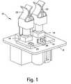
- FIG. 1shows a perspective view of the terminals and enabling switches of the power socket of the present invention with the casing removed;
- FIG. 2shows a bottom perspective view of the power socket of FIG. 1 ;
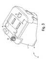
- FIG. 3shows a top perspective view of the power socket with the casing in place
- FIG. 4is a side perspective view of the power socket with the casing in place
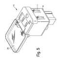
- FIG. 5is a top perspective view of the power socket showing the cover of the casing open 180°;
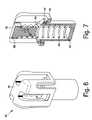
- FIG. 6shows one of the plungers which operate the enabling switches of the power socket
- FIG. 7is a cutaway view of the plunger of FIG. 6 ;
- FIG. 8shows one terminal of the power socket with the plunger in place
- FIG. 9is a cutaway view of the terminal and plunger.
- FIG. 1shows the interior of the power socket according to the present invention.
- the external appearance, with the cover open,is shown in FIG. 5 .
- the power socket 10includes a base 8 on which is mounted a printed circuit board 14 which has mounted thereon two switches 16 and 18 .
- the two switches 16 and 18are connected to terminals 20 mounted on the printed circuit board. These are visible in the bottom view of FIG. 2 .
- These terminalsare typically low voltage terminals which control a control circuit once the switches are actuated to provide the higher voltage/current electrical power to the terminals 22 , for example, to connect the AC hot and neutral power leads from, for example a DC-AC inverter, to the terminals 22 .
- an illumination sourcesuch as an LED 24 may be provided on the printed circuit board for illuminating a display portion of the socket when power is provided to terminal 22 .
- the other ends of terminals 22are shown in FIG. 2 in the bottom view and connect to a suitable AC connector. This connector would provide both the hot and neutral as well as the ground connection to the socket.
- FIG. 3shows a top view of the power socket with the casing in place, but with the hinged top cover removed.
- the casing 11comprises a housing on which is provided a safety slider 27 .
- the casing 11can be a snap-fit on base 8 .
- the safety sliderhas openings which align with the openings in the casing to expose the terminals 22 when the safety slider is slid to one side. Otherwise, the terminals 22 are not exposed when the slider is in the safety position.
- the slidermay be spring loaded so that it slides back to the safety position although it need not be and instead can have a lock or detent to lock or hold it in the safety position.
- a ground opening 25is provided for the ground connector of an electrical plug.
- a light pipe 26s provided which the LED 24 illuminates when power is on.
- a torsion spring 28may also be provided to allow the cover 30 , as shown in FIG. 5 , to spring back closed.
- FIG. 4shows a bottom perspective view of the power socket with the cover closed.
- the sockets 32 and 34 for terminals 20 and 22 , respectively,are also shown.
- Socket 32is the low voltage connector coupled to the switches 16 and 18 and socket 34 is the AC connector.
- FIGS. 6 and 7show the plungers 35 which actuate the switches 16 and 18 .
- the plungers 35are located in the center of the terminals 22 shown in FIG. 1 .
- Each plungercomprises an actuating member 36 including a top holder 38 which holds a compression spring 40 in place.
- the compression springis located in a bottom can 42 which has a shoulder 44 resting on a shoulder 46 of the actuating member 36 .
- plungers 35are made of an insulating material such as plastic.
- plungers 35are of integral construction, or made of a minimal number of pieces to allow insertion of spring 40 .
- each terminal 22includes two opposed surfaces for electrically and frictionally engaging the prong of the electrical connector and the plunger associated with the terminal is preferably disposed in a centered orientation with respect to the terminal opposed surfaces so as to be actuated by the connector prong when the prong is inerted. See also FIGS. 8 and 9 .
- two plungersare preferably provided, each actuating a respective switch 16 and 18 , although one could be used.
- the power socketcan be connected as shown in FIGS. 10A and 10B of U.S. Pat. No. 6,495,775, the entire disclosure of which is incorporated by reference herein.
- itis connected as shown in FIG. 10A of U.S. Pat. No. 6,495,775.
- the switchescan be connected in different ways. For example, only one of the switches need be used. As shown in FIGS. 1 and 2 , three terminals 20 are provided connected to the switches so that one of the terminals may be common to both switches. Alternatively, four terminals can be provided, two for each switch. As shown in FIG.
Landscapes
- Details Of Connecting Devices For Male And Female Coupling (AREA)
Abstract
Description
Claims (11)
Priority Applications (11)
| Application Number | Priority Date | Filing Date | Title |
|---|---|---|---|
| US11/070,435US6984141B1 (en) | 2005-03-02 | 2005-03-02 | Power socket device with enabling switch |
| JP2007557018AJP4842976B2 (en) | 2005-03-02 | 2006-01-03 | Power socket device with permission switch |
| PCT/US2006/000067WO2006093563A1 (en) | 2005-03-02 | 2006-01-03 | Power socket device with enabling switch |
| MX2007010585AMX2007010585A (en) | 2005-03-02 | 2006-01-03 | Power socket device with enabling switch. |
| BRPI0606564-3ABRPI0606564A2 (en) | 2005-03-02 | 2006-01-03 | power socket device with enable switch |
| CN2006800067113ACN101133525B (en) | 2005-03-02 | 2006-01-03 | Power socket device with enabling switch |
| KR1020077022333AKR100908109B1 (en) | 2005-03-02 | 2006-01-03 | Power socket device with movable switch |
| EP06717292AEP1856773B1 (en) | 2005-03-02 | 2006-01-03 | Power socket device with enabling switch |
| CA2599898ACA2599898C (en) | 2005-03-02 | 2006-01-03 | Power socket device with enabling switch |
| ES06717292TES2387400T3 (en) | 2005-03-02 | 2006-01-03 | Power supply device with commissioning switch |
| JP2010188021AJP2010262941A (en) | 2005-03-02 | 2010-08-25 | Power socket device equipped with enabling switch |
Applications Claiming Priority (1)
| Application Number | Priority Date | Filing Date | Title |
|---|---|---|---|
| US11/070,435US6984141B1 (en) | 2005-03-02 | 2005-03-02 | Power socket device with enabling switch |
Publications (1)
| Publication Number | Publication Date |
|---|---|
| US6984141B1true US6984141B1 (en) | 2006-01-10 |
Family
ID=35517751
Family Applications (1)
| Application Number | Title | Priority Date | Filing Date |
|---|---|---|---|
| US11/070,435Expired - LifetimeUS6984141B1 (en) | 2005-03-02 | 2005-03-02 | Power socket device with enabling switch |
Country Status (10)
| Country | Link |
|---|---|
| US (1) | US6984141B1 (en) |
| EP (1) | EP1856773B1 (en) |
| JP (2) | JP4842976B2 (en) |
| KR (1) | KR100908109B1 (en) |
| CN (1) | CN101133525B (en) |
| BR (1) | BRPI0606564A2 (en) |
| CA (1) | CA2599898C (en) |
| ES (1) | ES2387400T3 (en) |
| MX (1) | MX2007010585A (en) |
| WO (1) | WO2006093563A1 (en) |
Cited By (15)
| Publication number | Priority date | Publication date | Assignee | Title |
|---|---|---|---|---|
| US20060192439A1 (en)* | 2004-09-01 | 2006-08-31 | Russel Kenneth J | Power control center with solid state device for controlling power transmission |
| US20060237742A1 (en)* | 2004-09-01 | 2006-10-26 | Jones James L | Power control center with solid state device for controlling power transmission |
| US7575467B2 (en) | 2006-12-27 | 2009-08-18 | Thomas Wilmer Ferguson | Electrically safe receptacle |
| WO2010009979A1 (en)* | 2008-07-23 | 2010-01-28 | Rema Lipprandt Gmbh & Co. Kg | Charging plug-and-socket device for motor vehicles having an electric drive |
| FR2972862A1 (en)* | 2011-03-17 | 2012-09-21 | Andre Borg | Semi-flush socket outlet, has base including outer face provided with projections, where projections include higher part forming flush box, and lower part forming anchors for attaching socket outlet to wall bracket by clamping screws |
| FR3019387A1 (en)* | 2014-03-26 | 2015-10-02 | Ma Box Office M B O | POWER SUPPLY BLOCK. |
| CN105071078A (en)* | 2015-08-05 | 2015-11-18 | 四川永贵科技有限公司 | Jack structure with microswitch |
| US20160137083A1 (en)* | 2014-11-19 | 2016-05-19 | Hyundai Motor Company | Power outlet device |
| WO2017205252A1 (en)* | 2016-05-24 | 2017-11-30 | Hubbell Incorporated | Electrical receptacle |
| US10516347B1 (en) | 2019-03-27 | 2019-12-24 | Omron Automotive Electronics Co., Ltd. | Load detection method and apparatus |
| US10756495B1 (en)* | 2014-04-25 | 2020-08-25 | Jeffrey Baldwin | Electrical device for improved safety |
| US11283214B1 (en)* | 2021-02-10 | 2022-03-22 | Hong Kong Applied Science And Technology Research Institute Co., Ltd | Digital arc-less connector |
| US11509101B1 (en) | 2014-04-25 | 2022-11-22 | Jeffrey P. Baldwin | Locking electrical device |
| TWI866570B (en)* | 2023-10-31 | 2024-12-11 | 國立彰化師範大學 | Electrical connector device with anti-detachment function |
| US12418144B1 (en) | 2021-12-29 | 2025-09-16 | Titan3 Technology LLC | Gripping electrical receptacle |
Families Citing this family (9)
| Publication number | Priority date | Publication date | Assignee | Title |
|---|---|---|---|---|
| GB0808796D0 (en)* | 2008-05-15 | 2008-06-18 | Logicor Ltd | Electrical socket and method of use thereof |
| KR200459098Y1 (en)* | 2009-08-17 | 2012-03-19 | 주식회사 위너스 | Socket for switch concent |
| US8752435B2 (en) | 2011-03-09 | 2014-06-17 | Claude Belleville | Miniature high sensitivity pressure sensor |
| CN106058584B (en)* | 2016-06-16 | 2018-10-09 | 明光泰源安防科技有限公司 | A kind of safe insert row component |
| CN106450966A (en)* | 2016-12-05 | 2017-02-22 | 四川永贵科技有限公司 | Combined jack assembly with micro switch Linkage mechanism |
| CN106785725A (en)* | 2016-12-28 | 2017-05-31 | 南京理工大学 | A kind of safe family expenses three-pin socket |
| CN107316768B (en)* | 2017-07-27 | 2019-08-13 | 青岛华欧集团四海自动化控制工程有限公司 | Electrically activating switch |
| CN110061392B (en)* | 2019-05-29 | 2020-11-10 | 上海航天科工电器研究院有限公司 | Electric connector capable of hot plugging |
| EP4054022B1 (en)* | 2021-03-03 | 2024-04-24 | Albrecht Jung GmbH & Co. KG | Socket with increased personal protection and method for operating such a socket |
Citations (10)
| Publication number | Priority date | Publication date | Assignee | Title |
|---|---|---|---|---|
| US3246291A (en)* | 1962-06-14 | 1966-04-12 | California Inst Res Found | Seismometer |
| US3781495A (en) | 1972-09-29 | 1973-12-25 | J Splingaerd | Safety switch with hinge type interlocking mechanism for operating switch contacts or preventing actuation thereof |
| US5347095A (en)* | 1991-07-05 | 1994-09-13 | Abraham Zeder | Electrical receptacle for use with annunciator apparatus for monitoring electrical connections |
| US5374199A (en) | 1993-07-30 | 1994-12-20 | Chung; Chien-Lin | Safety receptacle |
| US5865635A (en) | 1997-12-09 | 1999-02-02 | Hsiang; Yu-Lung | Safety socket |
| US5928019A (en)* | 1997-12-19 | 1999-07-27 | Chen; Chih-Ching | Safety socket |
| US5984700A (en)* | 1997-07-25 | 1999-11-16 | Chang; Chi Tsai | Safety receptacle |
| US6111210A (en)* | 1999-07-30 | 2000-08-29 | Allison; John B. | Electrical safety outlet |
| US6495775B2 (en) | 2001-02-12 | 2002-12-17 | Casco Products Corporation | Power socket device with enabling switch and method of operation |
| US6914205B2 (en)* | 2002-02-19 | 2005-07-05 | Methode Electronics Malta Ltd. | Operating switch for a motor vehicle with a movable protective device |
Family Cites Families (7)
| Publication number | Priority date | Publication date | Assignee | Title |
|---|---|---|---|---|
| DE2418634A1 (en)* | 1974-04-18 | 1975-10-30 | Schaltbau Gmbh | Plug-in connector with actuator and intermediate element - has tension released spring latch locking intermediate element and socket |
| FR2582146A1 (en)* | 1985-05-14 | 1986-11-21 | Osmond Max | CIRCUIT BREAKER POWER SUPPLY DEVICE AND ELECTRICAL OUTLET INCORPORATING THE SAME |
| JPH03119969U (en)* | 1990-03-22 | 1991-12-10 | ||
| JPH0765889A (en)* | 1993-08-10 | 1995-03-10 | Kanrin Sho | Safety plug socket |
| CN2245809Y (en)* | 1995-08-16 | 1997-01-22 | 吴登峰 | Safety electric plug seat |
| JPH1083749A (en)* | 1996-09-05 | 1998-03-31 | Jidosha Kiki Co Ltd | Pressure switch and pump equipped with it |
| AU2001273038A1 (en)* | 2000-06-28 | 2002-01-08 | Tru-Connector Corporation | Electrical connector with switch-actuating sleeve |
- 2005
- 2005-03-02USUS11/070,435patent/US6984141B1/ennot_activeExpired - Lifetime
- 2006
- 2006-01-03CNCN2006800067113Apatent/CN101133525B/enactiveActive
- 2006-01-03JPJP2007557018Apatent/JP4842976B2/enactiveActive
- 2006-01-03KRKR1020077022333Apatent/KR100908109B1/ennot_activeExpired - Fee Related
- 2006-01-03ESES06717292Tpatent/ES2387400T3/enactiveActive
- 2006-01-03BRBRPI0606564-3Apatent/BRPI0606564A2/ennot_activeIP Right Cessation
- 2006-01-03EPEP06717292Apatent/EP1856773B1/enactiveActive
- 2006-01-03MXMX2007010585Apatent/MX2007010585A/enactiveIP Right Grant
- 2006-01-03WOPCT/US2006/000067patent/WO2006093563A1/enactiveApplication Filing
- 2006-01-03CACA2599898Apatent/CA2599898C/ennot_activeExpired - Fee Related
- 2010
- 2010-08-25JPJP2010188021Apatent/JP2010262941A/ennot_activeWithdrawn
Patent Citations (10)
| Publication number | Priority date | Publication date | Assignee | Title |
|---|---|---|---|---|
| US3246291A (en)* | 1962-06-14 | 1966-04-12 | California Inst Res Found | Seismometer |
| US3781495A (en) | 1972-09-29 | 1973-12-25 | J Splingaerd | Safety switch with hinge type interlocking mechanism for operating switch contacts or preventing actuation thereof |
| US5347095A (en)* | 1991-07-05 | 1994-09-13 | Abraham Zeder | Electrical receptacle for use with annunciator apparatus for monitoring electrical connections |
| US5374199A (en) | 1993-07-30 | 1994-12-20 | Chung; Chien-Lin | Safety receptacle |
| US5984700A (en)* | 1997-07-25 | 1999-11-16 | Chang; Chi Tsai | Safety receptacle |
| US5865635A (en) | 1997-12-09 | 1999-02-02 | Hsiang; Yu-Lung | Safety socket |
| US5928019A (en)* | 1997-12-19 | 1999-07-27 | Chen; Chih-Ching | Safety socket |
| US6111210A (en)* | 1999-07-30 | 2000-08-29 | Allison; John B. | Electrical safety outlet |
| US6495775B2 (en) | 2001-02-12 | 2002-12-17 | Casco Products Corporation | Power socket device with enabling switch and method of operation |
| US6914205B2 (en)* | 2002-02-19 | 2005-07-05 | Methode Electronics Malta Ltd. | Operating switch for a motor vehicle with a movable protective device |
Cited By (25)
| Publication number | Priority date | Publication date | Assignee | Title |
|---|---|---|---|---|
| US20060192439A1 (en)* | 2004-09-01 | 2006-08-31 | Russel Kenneth J | Power control center with solid state device for controlling power transmission |
| US7268446B2 (en)* | 2004-09-01 | 2007-09-11 | Yazaki North America, Inc. | Power control center with solid state device for controlling power transmission |
| US7268447B2 (en)* | 2004-09-01 | 2007-09-11 | Yazaki North America, Inc. | Power control center with solid state device for controlling power transmission |
| US7288853B1 (en)* | 2004-09-01 | 2007-10-30 | Yazaki North America, Inc. | Power control center with solid state device for controlling power transmission |
| US20060237742A1 (en)* | 2004-09-01 | 2006-10-26 | Jones James L | Power control center with solid state device for controlling power transmission |
| US7575467B2 (en) | 2006-12-27 | 2009-08-18 | Thomas Wilmer Ferguson | Electrically safe receptacle |
| WO2010009979A1 (en)* | 2008-07-23 | 2010-01-28 | Rema Lipprandt Gmbh & Co. Kg | Charging plug-and-socket device for motor vehicles having an electric drive |
| FR2972862A1 (en)* | 2011-03-17 | 2012-09-21 | Andre Borg | Semi-flush socket outlet, has base including outer face provided with projections, where projections include higher part forming flush box, and lower part forming anchors for attaching socket outlet to wall bracket by clamping screws |
| FR3019387A1 (en)* | 2014-03-26 | 2015-10-02 | Ma Box Office M B O | POWER SUPPLY BLOCK. |
| US12283780B1 (en) | 2014-04-25 | 2025-04-22 | Titan3 Technology LLC | Locking electrical device |
| US11509101B1 (en) | 2014-04-25 | 2022-11-22 | Jeffrey P. Baldwin | Locking electrical device |
| US11862905B1 (en) | 2014-04-25 | 2024-01-02 | Titan3 Technology LLC | Locking electrical device |
| US10756495B1 (en)* | 2014-04-25 | 2020-08-25 | Jeffrey Baldwin | Electrical device for improved safety |
| US11171455B1 (en) | 2014-04-25 | 2021-11-09 | Jeffrey P. Baldwin | Electrical device |
| US11670898B1 (en) | 2014-04-25 | 2023-06-06 | Titan3 Technology LLC | Electrical device |
| US20160137083A1 (en)* | 2014-11-19 | 2016-05-19 | Hyundai Motor Company | Power outlet device |
| CN106207645A (en)* | 2014-11-19 | 2016-12-07 | 现代自动车株式会社 | Electrical source socket |
| US10290981B2 (en)* | 2014-11-19 | 2019-05-14 | Hyundai Motor Company | Power outlet device |
| CN105071078A (en)* | 2015-08-05 | 2015-11-18 | 四川永贵科技有限公司 | Jack structure with microswitch |
| WO2017205252A1 (en)* | 2016-05-24 | 2017-11-30 | Hubbell Incorporated | Electrical receptacle |
| US10038283B2 (en) | 2016-05-24 | 2018-07-31 | Hubbell Incorporated | Electrical receptacle |
| US10516347B1 (en) | 2019-03-27 | 2019-12-24 | Omron Automotive Electronics Co., Ltd. | Load detection method and apparatus |
| US11283214B1 (en)* | 2021-02-10 | 2022-03-22 | Hong Kong Applied Science And Technology Research Institute Co., Ltd | Digital arc-less connector |
| US12418144B1 (en) | 2021-12-29 | 2025-09-16 | Titan3 Technology LLC | Gripping electrical receptacle |
| TWI866570B (en)* | 2023-10-31 | 2024-12-11 | 國立彰化師範大學 | Electrical connector device with anti-detachment function |
Also Published As
| Publication number | Publication date |
|---|---|
| EP1856773A1 (en) | 2007-11-21 |
| ES2387400T3 (en) | 2012-09-21 |
| EP1856773B1 (en) | 2012-06-13 |
| CA2599898C (en) | 2010-11-30 |
| CA2599898A1 (en) | 2006-09-08 |
| BRPI0606564A2 (en) | 2010-01-19 |
| CN101133525A (en) | 2008-02-27 |
| JP2008532225A (en) | 2008-08-14 |
| JP2010262941A (en) | 2010-11-18 |
| WO2006093563A1 (en) | 2006-09-08 |
| JP4842976B2 (en) | 2011-12-21 |
| CN101133525B (en) | 2010-12-15 |
| EP1856773A4 (en) | 2011-09-07 |
| KR20070108411A (en) | 2007-11-09 |
| MX2007010585A (en) | 2007-10-23 |
| KR100908109B1 (en) | 2009-07-16 |
Similar Documents
| Publication | Publication Date | Title |
|---|---|---|
| US6984141B1 (en) | Power socket device with enabling switch | |
| CA2438179C (en) | Power socket device with enabling switch and method of operation | |
| US7317600B2 (en) | Circuit interrupting device with automatic end of life test | |
| US5320545A (en) | Household safety receptacle | |
| US7009473B2 (en) | Ground-fault circuit interrupter with reverse wiring protection | |
| US6580344B2 (en) | Ground fault interruption receptacle | |
| US2907855A (en) | Electric line switch | |
| US20070229202A1 (en) | Circuit interruption device with indicator having function of auto-monitoring and multi-protecting circuit | |
| AU2007331365C1 (en) | Electric connection device with light indicator | |
| US20080094765A1 (en) | Circuit interrupting device with automatic end of life test | |
| US20090278410A1 (en) | Pre-Set Timer and Plug Adapter | |
| CN208571136U (en) | A kind of intelligent socket and intelligent charging system | |
| EP0329974B1 (en) | Electrical safety socket | |
| CN113154279B (en) | Connecting device, connecting assembly and refrigerator for illumination power supply of electric appliance | |
| KR20150097881A (en) | Electric outlet apparatus for intercepting standby power | |
| BE1010599A6 (en) | Outlet. | |
| KR960001785Y1 (en) | Cassette record with two or more power sockets | |
| JP3103432U (en) | Plug with switch | |
| KR200170054Y1 (en) | Power switch | |
| CN2909602Y (en) | Multifunction power connector socket | |
| GB2213331A (en) | Key-operated plug to prevent unauthorised current use | |
| GB2399695A (en) | Safety shutter arrangement for electrical devices | |
| CA2047111A1 (en) | Circuit tester | |
| WO2002035661A1 (en) | Electrical power outlet |
Legal Events
| Date | Code | Title | Description |
|---|---|---|---|
| AS | Assignment | Owner name:CASCO PRODUCTS CORPORATION, CONNECTICUT Free format text:ASSIGNMENT OF ASSIGNORS INTEREST;ASSIGNORS:BESKI, SR., RICHARD A.;JACQUES, TONY;REEL/FRAME:015853/0935 Effective date:20050329 | |
| STCF | Information on status: patent grant | Free format text:PATENTED CASE | |
| AS | Assignment | Owner name:LEHMAN COMMERCIAL PAPER, INC., NEW YORK Free format text:GUARANTEE AND COLLATERAL AGREEMENT;ASSIGNOR:CASCO PRODUCTS CORPORATION;REEL/FRAME:020525/0532 Effective date:20071203 Owner name:LEHMAN COMMERCIAL PAPER, INC.,NEW YORK Free format text:GUARANTEE AND COLLATERAL AGREEMENT;ASSIGNOR:CASCO PRODUCTS CORPORATION;REEL/FRAME:020525/0532 Effective date:20071203 | |
| FPAY | Fee payment | Year of fee payment:4 | |
| AS | Assignment | Owner name:BARCLAYS BANK PLC, NEW YORK Free format text:ASSIGNMENT OF SECURITY INTEREST;ASSIGNOR:LEHMAN COMMERCIAL PAPER INC.;REEL/FRAME:027068/0254 Effective date:20111014 | |
| AS | Assignment | Owner name:CASCO PRODUCTS CORPORATION, CONNECTICUT Free format text:PATENT RELEASE;ASSIGNOR:BARCLAYS BANK PLC;REEL/FRAME:029310/0220 Effective date:20121115 | |
| FPAY | Fee payment | Year of fee payment:8 | |
| AS | Assignment | Owner name:ROYAL BANK OF CANADA, ONTARIO Free format text:SECURITY AGREEMENT;ASSIGNORS:CASCO PRODUCTS CORPORATION;ARC AUTOMOTIVE, INC.;REEL/FRAME:031182/0001 Effective date:20121115 | |
| AS | Assignment | Owner name:CASCO PRODUCTS CORPORATION, CONNECTICUT Free format text:RELEASE BY SECURED PARTY;ASSIGNOR:ROYAL BANK OF CANADA, AS AGENT;REEL/FRAME:033778/0787 Effective date:20140919 Owner name:ARC AUTOMOTIVE, INC., TENNESSEE Free format text:RELEASE BY SECURED PARTY;ASSIGNOR:ROYAL BANK OF CANADA, AS AGENT;REEL/FRAME:033778/0787 Effective date:20140919 | |
| FPAY | Fee payment | Year of fee payment:12 |