US6984063B2 - Apparatus for mixing and dispensing components - Google Patents
Apparatus for mixing and dispensing componentsDownload PDFInfo
- Publication number
- US6984063B2 US6984063B2US10/438,471US43847103AUS6984063B2US 6984063 B2US6984063 B2US 6984063B2US 43847103 AUS43847103 AUS 43847103AUS 6984063 B2US6984063 B2US 6984063B2
- Authority
- US
- United States
- Prior art keywords
- mixing
- chamber
- dispensing
- mixing chamber
- portal
- Prior art date
- Legal status (The legal status is an assumption and is not a legal conclusion. Google has not performed a legal analysis and makes no representation as to the accuracy of the status listed.)
- Expired - Lifetime, expires
Links
Images


Classifications
- A—HUMAN NECESSITIES
- A61—MEDICAL OR VETERINARY SCIENCE; HYGIENE
- A61B—DIAGNOSIS; SURGERY; IDENTIFICATION
- A61B17/00—Surgical instruments, devices or methods
- A61B17/56—Surgical instruments or methods for treatment of bones or joints; Devices specially adapted therefor
- A61B17/58—Surgical instruments or methods for treatment of bones or joints; Devices specially adapted therefor for osteosynthesis, e.g. bone plates, screws or setting implements
- A61B17/88—Osteosynthesis instruments; Methods or means for implanting or extracting internal or external fixation devices
- A61B17/8802—Equipment for handling bone cement or other fluid fillers
- A61B17/8805—Equipment for handling bone cement or other fluid fillers for introducing fluid filler into bone or extracting it
- A61B17/8822—Equipment for handling bone cement or other fluid fillers for introducing fluid filler into bone or extracting it characterised by means facilitating expulsion of fluid from the introducer, e.g. a screw pump plunger, hydraulic force transmissions, application of vibrations or a vacuum
- B—PERFORMING OPERATIONS; TRANSPORTING
- B01—PHYSICAL OR CHEMICAL PROCESSES OR APPARATUS IN GENERAL
- B01F—MIXING, e.g. DISSOLVING, EMULSIFYING OR DISPERSING
- B01F27/00—Mixers with rotary stirring devices in fixed receptacles; Kneaders
- B01F27/05—Stirrers
- B01F27/11—Stirrers characterised by the configuration of the stirrers
- B01F27/114—Helically shaped stirrers, i.e. stirrers comprising a helically shaped band or helically shaped band sections
- B01F27/1142—Helically shaped stirrers, i.e. stirrers comprising a helically shaped band or helically shaped band sections of the corkscrew type
- B—PERFORMING OPERATIONS; TRANSPORTING
- B01—PHYSICAL OR CHEMICAL PROCESSES OR APPARATUS IN GENERAL
- B01F—MIXING, e.g. DISSOLVING, EMULSIFYING OR DISPERSING
- B01F33/00—Other mixers; Mixing plants; Combinations of mixers
- B01F33/50—Movable or transportable mixing devices or plants
- B01F33/501—Movable mixing devices, i.e. readily shifted or displaced from one place to another, e.g. portable during use
- B01F33/5011—Movable mixing devices, i.e. readily shifted or displaced from one place to another, e.g. portable during use portable during use, e.g. hand-held
- B—PERFORMING OPERATIONS; TRANSPORTING
- B01—PHYSICAL OR CHEMICAL PROCESSES OR APPARATUS IN GENERAL
- B01F—MIXING, e.g. DISSOLVING, EMULSIFYING OR DISPERSING
- B01F33/00—Other mixers; Mixing plants; Combinations of mixers
- B01F33/50—Movable or transportable mixing devices or plants
- B01F33/501—Movable mixing devices, i.e. readily shifted or displaced from one place to another, e.g. portable during use
- B01F33/5014—Movable mixing devices, i.e. readily shifted or displaced from one place to another, e.g. portable during use movable by human force, e.g. kitchen or table devices
- B—PERFORMING OPERATIONS; TRANSPORTING
- B01—PHYSICAL OR CHEMICAL PROCESSES OR APPARATUS IN GENERAL
- B01F—MIXING, e.g. DISSOLVING, EMULSIFYING OR DISPERSING
- B01F35/00—Accessories for mixers; Auxiliary operations or auxiliary devices; Parts or details of general application
- B01F35/30—Driving arrangements; Transmissions; Couplings; Brakes
- B01F35/32—Driving arrangements
- B—PERFORMING OPERATIONS; TRANSPORTING
- B01—PHYSICAL OR CHEMICAL PROCESSES OR APPARATUS IN GENERAL
- B01F—MIXING, e.g. DISSOLVING, EMULSIFYING OR DISPERSING
- B01F35/00—Accessories for mixers; Auxiliary operations or auxiliary devices; Parts or details of general application
- B01F35/71—Feed mechanisms
- B01F35/713—Feed mechanisms comprising breaking packages or parts thereof, e.g. piercing or opening sealing elements between compartments or cartridges
- B01F35/7131—Breaking or perforating packages, containers or vials
- B—PERFORMING OPERATIONS; TRANSPORTING
- B01—PHYSICAL OR CHEMICAL PROCESSES OR APPARATUS IN GENERAL
- B01F—MIXING, e.g. DISSOLVING, EMULSIFYING OR DISPERSING
- B01F35/00—Accessories for mixers; Auxiliary operations or auxiliary devices; Parts or details of general application
- B01F35/71—Feed mechanisms
- B01F35/714—Feed mechanisms for feeding predetermined amounts
- B—PERFORMING OPERATIONS; TRANSPORTING
- B01—PHYSICAL OR CHEMICAL PROCESSES OR APPARATUS IN GENERAL
- B01F—MIXING, e.g. DISSOLVING, EMULSIFYING OR DISPERSING
- B01F35/00—Accessories for mixers; Auxiliary operations or auxiliary devices; Parts or details of general application
- B01F35/71—Feed mechanisms
- B01F35/716—Feed mechanisms characterised by the relative arrangement of the containers for feeding or mixing the components
- B01F35/7163—Feed mechanisms characterised by the relative arrangement of the containers for feeding or mixing the components the containers being connected in a mouth-to-mouth, end-to-end disposition, i.e. the openings are juxtaposed before contacting the contents
- B—PERFORMING OPERATIONS; TRANSPORTING
- B01—PHYSICAL OR CHEMICAL PROCESSES OR APPARATUS IN GENERAL
- B01F—MIXING, e.g. DISSOLVING, EMULSIFYING OR DISPERSING
- B01F35/00—Accessories for mixers; Auxiliary operations or auxiliary devices; Parts or details of general application
- B01F35/75—Discharge mechanisms
- B01F35/751—Discharging by opening a gate, e.g. using discharge paddles
- B—PERFORMING OPERATIONS; TRANSPORTING
- B01—PHYSICAL OR CHEMICAL PROCESSES OR APPARATUS IN GENERAL
- B01F—MIXING, e.g. DISSOLVING, EMULSIFYING OR DISPERSING
- B01F35/00—Accessories for mixers; Auxiliary operations or auxiliary devices; Parts or details of general application
- B01F35/75—Discharge mechanisms
- B01F35/752—Discharge mechanisms with arrangements for converting the mechanism from mixing to discharging, e.g. by either guiding a mixture back into a receptacle or discharging it
- B—PERFORMING OPERATIONS; TRANSPORTING
- B01—PHYSICAL OR CHEMICAL PROCESSES OR APPARATUS IN GENERAL
- B01F—MIXING, e.g. DISSOLVING, EMULSIFYING OR DISPERSING
- B01F35/00—Accessories for mixers; Auxiliary operations or auxiliary devices; Parts or details of general application
- B01F35/75—Discharge mechanisms
- B01F35/754—Discharge mechanisms characterised by the means for discharging the components from the mixer
- B01F35/75425—Discharge mechanisms characterised by the means for discharging the components from the mixer using pistons or plungers
- B01F35/754251—Discharge mechanisms characterised by the means for discharging the components from the mixer using pistons or plungers reciprocating in the mixing receptacle
- A—HUMAN NECESSITIES
- A61—MEDICAL OR VETERINARY SCIENCE; HYGIENE
- A61B—DIAGNOSIS; SURGERY; IDENTIFICATION
- A61B17/00—Surgical instruments, devices or methods
- A61B17/56—Surgical instruments or methods for treatment of bones or joints; Devices specially adapted therefor
- A61B17/58—Surgical instruments or methods for treatment of bones or joints; Devices specially adapted therefor for osteosynthesis, e.g. bone plates, screws or setting implements
- A61B17/88—Osteosynthesis instruments; Methods or means for implanting or extracting internal or external fixation devices
- A61B17/8802—Equipment for handling bone cement or other fluid fillers
- A61B17/8833—Osteosynthesis tools specially adapted for handling bone cement or fluid fillers; Means for supplying bone cement or fluid fillers to introducing tools, e.g. cartridge handling means
- A61B2017/8838—Osteosynthesis tools specially adapted for handling bone cement or fluid fillers; Means for supplying bone cement or fluid fillers to introducing tools, e.g. cartridge handling means for mixing bone cement or fluid fillers
- A—HUMAN NECESSITIES
- A61—MEDICAL OR VETERINARY SCIENCE; HYGIENE
- A61B—DIAGNOSIS; SURGERY; IDENTIFICATION
- A61B50/00—Containers, covers, furniture or holders specially adapted for surgical or diagnostic appliances or instruments, e.g. sterile covers
- A61B2050/005—Containers, covers, furniture or holders specially adapted for surgical or diagnostic appliances or instruments, e.g. sterile covers with a lid or cover
- A61B2050/0062—Containers, covers, furniture or holders specially adapted for surgical or diagnostic appliances or instruments, e.g. sterile covers with a lid or cover closable by a combination of rotation and translation
- A61B2050/0064—Containers, covers, furniture or holders specially adapted for surgical or diagnostic appliances or instruments, e.g. sterile covers with a lid or cover closable by a combination of rotation and translation by screwing
- A—HUMAN NECESSITIES
- A61—MEDICAL OR VETERINARY SCIENCE; HYGIENE
- A61C—DENTISTRY; APPARATUS OR METHODS FOR ORAL OR DENTAL HYGIENE
- A61C5/00—Filling or capping teeth
- A61C5/60—Devices specially adapted for pressing or mixing capping or filling materials, e.g. amalgam presses
- A61C5/68—Mixing dental material components for immediate application to a site to be restored, e.g. a tooth cavity
- A—HUMAN NECESSITIES
- A61—MEDICAL OR VETERINARY SCIENCE; HYGIENE
- A61F—FILTERS IMPLANTABLE INTO BLOOD VESSELS; PROSTHESES; DEVICES PROVIDING PATENCY TO, OR PREVENTING COLLAPSING OF, TUBULAR STRUCTURES OF THE BODY, e.g. STENTS; ORTHOPAEDIC, NURSING OR CONTRACEPTIVE DEVICES; FOMENTATION; TREATMENT OR PROTECTION OF EYES OR EARS; BANDAGES, DRESSINGS OR ABSORBENT PADS; FIRST-AID KITS
- A61F2/00—Filters implantable into blood vessels; Prostheses, i.e. artificial substitutes or replacements for parts of the body; Appliances for connecting them with the body; Devices providing patency to, or preventing collapsing of, tubular structures of the body, e.g. stents
- A61F2/02—Prostheses implantable into the body
- A61F2/30—Joints
- A61F2002/30001—Additional features of subject-matter classified in A61F2/28, A61F2/30 and subgroups thereof
- A61F2002/30316—The prosthesis having different structural features at different locations within the same prosthesis; Connections between prosthetic parts; Special structural features of bone or joint prostheses not otherwise provided for
- A61F2002/30535—Special structural features of bone or joint prostheses not otherwise provided for
- A61F2002/30561—Special structural features of bone or joint prostheses not otherwise provided for breakable or frangible
- A—HUMAN NECESSITIES
- A61—MEDICAL OR VETERINARY SCIENCE; HYGIENE
- A61F—FILTERS IMPLANTABLE INTO BLOOD VESSELS; PROSTHESES; DEVICES PROVIDING PATENCY TO, OR PREVENTING COLLAPSING OF, TUBULAR STRUCTURES OF THE BODY, e.g. STENTS; ORTHOPAEDIC, NURSING OR CONTRACEPTIVE DEVICES; FOMENTATION; TREATMENT OR PROTECTION OF EYES OR EARS; BANDAGES, DRESSINGS OR ABSORBENT PADS; FIRST-AID KITS
- A61F2/00—Filters implantable into blood vessels; Prostheses, i.e. artificial substitutes or replacements for parts of the body; Appliances for connecting them with the body; Devices providing patency to, or preventing collapsing of, tubular structures of the body, e.g. stents
- A61F2/02—Prostheses implantable into the body
- A61F2/30—Joints
- A61F2/46—Special tools for implanting artificial joints
- A61F2002/4685—Special tools for implanting artificial joints by means of vacuum
- A—HUMAN NECESSITIES
- A61—MEDICAL OR VETERINARY SCIENCE; HYGIENE
- A61F—FILTERS IMPLANTABLE INTO BLOOD VESSELS; PROSTHESES; DEVICES PROVIDING PATENCY TO, OR PREVENTING COLLAPSING OF, TUBULAR STRUCTURES OF THE BODY, e.g. STENTS; ORTHOPAEDIC, NURSING OR CONTRACEPTIVE DEVICES; FOMENTATION; TREATMENT OR PROTECTION OF EYES OR EARS; BANDAGES, DRESSINGS OR ABSORBENT PADS; FIRST-AID KITS
- A61F2250/00—Special features of prostheses classified in groups A61F2/00 - A61F2/26 or A61F2/82 or A61F9/00 or A61F11/00 or subgroups thereof
- A61F2250/0058—Additional features; Implant or prostheses properties not otherwise provided for
- A61F2250/0071—Additional features; Implant or prostheses properties not otherwise provided for breakable or frangible
- B—PERFORMING OPERATIONS; TRANSPORTING
- B01—PHYSICAL OR CHEMICAL PROCESSES OR APPARATUS IN GENERAL
- B01F—MIXING, e.g. DISSOLVING, EMULSIFYING OR DISPERSING
- B01F2101/00—Mixing characterised by the nature of the mixed materials or by the application field
- B01F2101/20—Mixing of ingredients for bone cement
- B—PERFORMING OPERATIONS; TRANSPORTING
- B01—PHYSICAL OR CHEMICAL PROCESSES OR APPARATUS IN GENERAL
- B01F—MIXING, e.g. DISSOLVING, EMULSIFYING OR DISPERSING
- B01F35/00—Accessories for mixers; Auxiliary operations or auxiliary devices; Parts or details of general application
- B01F35/30—Driving arrangements; Transmissions; Couplings; Brakes
- B01F35/32—Driving arrangements
- B01F35/32005—Type of drive
- B01F35/3202—Hand driven
Definitions
- This inventionrelates to methods and apparatus for mixing and dispensing at least two components.
- the apparatus and methods of the inventionare particularly useful to prepare bone cement and deliver the bone cement into the skeletal structure of patients, such as to injured spinal vertebrae.
- vertebrae fracturesoccur each year, many in older women as a result of osteoporosis.
- the pain and loss of movement accompanying vertebral fracturesseverely limits activity and reduces the quality of life.
- a procedure called “vertebroplasty”is a less-invasive alternative to surgery, with fewer attendant risks, and has proved extremely effective in reducing or eliminating the pain caused by spinal fractures.
- Vertebroplastyinvolves injecting radiopaque bone cement into the damaged vertebral body by way of a needle or cannula using x-ray (fluoroscopy) to visualize and monitor delivery.
- x-rayfluoroscopy
- vertebroplastyis performed by radiologists, neurosurgeons, and orthopedic surgeons.
- bone cementis prepared by mixing bone-cement powder (e.g., polymethylmethacrylate “PMMA”), liquid monomer (e.g., methyl methacrylate monomer), with an x-ray contrast agent (e.g., barium sulfate), to form a fluid mixture.
- PMMApolymethylmethacrylate
- liquid monomere.g., methyl methacrylate monomer
- an x-ray contrast agente.g., barium sulfate
- bone-cement powderis stored in a flexible bag, pouch, bottle, or similar container, while the liquid monomer is stored for shipment and handling in a vial or tube, usually formed from glass. Bone cement sets and hardens rapidly, so the doctors must work quickly and efficiently.
- a typical bone-cement mixturemay comprise 15 g polymethylmethacrylate powder, 5–10 g of methyl methacrylate monomer, and 5–8 grams of sterile barium sulfate for radiographic visualization of the cement.
- the radiopaque bone-cement mixtureis placed in a cannula-type dispensation system, the needle portion is inserted into the patient, properly positioned, and the bone cement slowly injected into the subject vertebra using x-ray guidance allowing the doctors to see the mixture actively infuse.
- the flowis stopped and the needle is removed.
- stopping the flowis easier said than done.
- Bone cementhardens very quickly, even more so upon exposure to air. Also, it is important that the cement delivered into the bone be virtually free of any entrapped air bubbles or air pockets.
- bone cementis typically hand mixed in an open environment directly before the procedure using a tongue depressor or spatula. The mixed cement is then manually transferred from the mixing vessel to a separate dispensing device, such as a syringe. Removal of the mixed cement from the mixing vessel into the caulking gun or syringe is cumbersome, time consuming, and has the potential for being mishandled, dropped or contaminated.
- the resulting bone cementsince it has been exposed to air, is less fluid and harder to force through the cannula into the vertebrae. Accordingly, more pressure must be exerted by the attending physician on the dispensing device. The increased pressure requirement makes control difficult and increases the likelihood that too much cement will be injected. For example, when the x-ray indicates that the vertebrae is filled, it is difficult to stop the cement flow out of the cannula and overflow of the cement into the surrounding tissues can result. This is unsafe for the patient since the excess cement may leak out of the vertebral body into surrounding tissue and vascular structures. In some cases, surgery may be required to remove the excess cement.
- Bone cement monomersincluding methyl methacrylate
- acrylate monomerirritates skin and contact with minute concentrations can cause sensitization. Accordingly, handling requires the use of suitable gloves. So, not only must attending clinicians worry about the deleterious effects of incorporating air bubbles into the bone cement during the cumbersome hand mixing, but also be concerned with health and safety issues in connection with toxic methyl methacrylate vapors.
- What is neededis a mixing and dispensing device that can mix the components of bone cement in a sealed environment and provide increased control on dispensation so that the operator can readily stop the bone-cement flow when the desired amount has been dispensed.
- the inventionrelates to apparatus, kits, and methods for mixing and dispensing components.
- the methods and apparatus of the inventioncan be adapted to mix and dispense any components but are particularly useful where the components require isolation from the surrounding atmosphere, for example, in cases where the components are adversely affected by air or because the components give off toxic vapors.
- the methods and apparatus of the inventionare particularly appropriate where controlled and consistent mixing and dispensing are desired as well as limiting the exposure of those in proximity to any noxious fumes generated during the mixing process.
- the inventionis directed to a mixing and dispensing unit for mixing and dispensing biocompatible bone fillers.
- the mixing and dispensing unit of the inventionis useful to mix and dispense the components of biocompatible bone fillers for delivery into human or animal patients.
- biocompatible fillers suitable for use in the inventioninclude, but are not limited to, bone cements, calcium-based fillers, bioglass, bone substitutes, and grafts.
- the mixing and dispensing unit of the inventionallows facile addition of other components before or during the mixing process, for example, antibiotics, colorants, bone-morphogenic proteins, and opacifying agents.
- the mixing and dispensing unit of the inventionis useful in many medical procedures involving the preparation and delivery of biocompatible bone fillers into patients (both humans and animals), for example, vertebroplasty, tumor or bone-void filling, dental applications, in the treatment of avascular necrosis, and many others.
- the mixing and dispensing unit of the inventionis particularly suited to mix the components of radiopaque PMMA-based bone cement and inject the resulting radiopaque bone cement to repair, reinforce, or replace injured, diseased, or insufficient bone or skeletal structures, such as to injured or diseased spinal vertebrae of human or animal patients.
- deliveryis accomplished by way of a tube, hose, cannula, or needle.
- the apparatus of the invention for mixing and dispensing componentscomprises: (1) a sealed mixing chamber for mixing components; (2) a dispensing chamber isolated from the sealed mixing chamber; (3) a controllable portal to open a flow path between the sealed mixing chamber and the dispensing chamber so that the dispensing chamber can receive the mixed components after they are mixed; and (4) a drive mechanism associated with the dispensing chamber to force the mixed contents from the dispensing chamber.
- the sealed mixing chambercomprises a mixing unit; an access portal for receiving the components; and a vacuum portal for attachment to a vacuum supply.
- the mixing and dispensing unit of the inventionis preferably used in conjunction with a sealed container, which stores liquid monomer separately.
- the sealed mixing chamberis pre-packaged with bone-cement powder and the access portal is designed to sealably receive liquid monomer from the sealed container.
- the mixing and dispensing unit of the inventioncomprises a transfer assembly, preferably, a fluid transfer assembly.
- the transfer assembly of the inventionis constructed for cooperating with the sealed container containing the liquid monomer and the sealed mixing chamber for extracting the liquid monomer from the container in a closed loop operation and directly delivering the liquid monomer into the sealed mixing chamber containing the dry powder. This transfer operation is achieved upon demand by the user, while preventing those in the surrounding area from being exposed to the liquid monomer or noxious fumes.
- the sealed mixing chambercontrollably communicates with the dispensing chamber by a controllable portal.
- the controllable portalis closed.
- the controllable portalis opened creating a flow path whereby the dispensing chamber receives the bone cement.
- the dispensing chambercomprises a dispensing portal, preferably, adapted to connect to a flexible tube, high-pressure hose, cannula, or a standard needle to deliver the mixed bone cement to a patient's vertebra.
- the dispensing chamberalso communicates with a drive mechanism for forcing the bone cement through the dispensing portal and into the vertebroplasty delivery tube. In preferred embodiment, a single drive connection is used to mix the components and to dispense the components thereby reducing the number of manipulations required for mixing and dispensing bone cement.
- the access portal of the sealed mixing chambercomprises a self-sealing elastic member to permit injection of the liquid component via a needle.
- the mixing unitcomprises a helical mixing vane, and the drive mechanism for delivery is a reversible plunger.
- the apparatuscan include a mechanical switch for changing the configuration of the apparatus from a component mixing state to a mixture dispensing state.
- FIG. 1is an exploded perspective view, partially broken away, depicting the multi-component product handling and delivering system of the present invention
- FIG. 2is a side elevation view, partially broken away and partially in cross-section depicting the multi-component product handling and delivering system of FIG. 1 fully assembled;
- FIG. 3is an exploded perspective view of the transfer assembly member of the multi-component product handling and delivering system of present invention
- FIG. 4is a top plan view of the transfer assembly of FIG. 3 ;
- FIG. 5is a cross-sectional side elevation view of the transfer assembly taken along the line A—A of FIG. 4 ;
- FIG. 6is a side elevation view of the fully assembled multi-component system of the present invention, partially broken away and partially in cross-section;
- FIG. 7is an enlarged cross-sectional side elevation view detailing area 7 of FIG. 6 ;
- FIG. 8is an exploded perspective view of an alternate embodiment of the transfer assembly of the present invention.
- FIG. 9is a cross-sectional side elevation view of the transfer assembly of FIG. 8 ;
- FIG. 10is a cross-sectional side elevation view of the housing forming the transfer assembly of FIG. 8 ;
- FIG. 11is a top plan view of the housing of FIG. 10 .
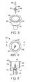
- FIG. 12is a perspective view of a fully assembled mixing and dispensing unit of the invention.
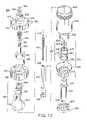
- FIGS. 13 and 14are exploded and cross-section side elevation views of a mixing and dispensing unit of the invention depicting the interrelation of component parts;
- FIG. 15is a cross-sectional view of a mixing and dispensing unit of the invention in the mixing stage
- FIG. 16is a cross-sectional view of a mixing and dispensing unit of the invention depicting the mixed components transferring to the dispensing chamber;
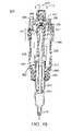
- FIGS. 17 and 18are cross-sectional views of a mixing and dispensing unit of the invention depicting the mixed components being dispensed from the dispensing chamber.
- FIGS. 1–11By referring to FIGS. 1–11 , along with the following detailed discussion, the construction and operation of the preferred multi-component product handling and delivering systems of the present invention can best be understood. However, as will become evident from this disclosure, further alternate embodiments of the present invention can be implemented without departing from the scope of the present invention. Consequently, the embodiments detailed in FIGS. 1–11 , and in the following detailed disclosure, are intended for exemplary purposes, and not as a limitation of the present invention.
- the present inventioncan be employed with any type of vessel used to intermix the two or more components.
- the present inventionis not limited to combining or mixing bone cements.
- the components of the multi-component product handling and delivering systems of the present inventioncan be packaged and sold together as a kit.
- multi-component product handling and delivering system 20 of the present inventionis fully depicted as comprising container 21 , integrated bone cement handling and delivery system 22 , and transfer assembly 23 , preferably, a fluid transfer assembly.
- Container 21is preferably a sealed container, more preferably, a sealed container designed for containing corrosive chemicals, such as liquid monomer.
- “sealed”means that the container's contents are prevented from leaking during handling and transport and are protected from air.
- integrated bone cement handling and delivery system 22comprises cover 24 that is threadedly mounted to vessel 25 .
- the second component of the bone cementwhich comprises dry powder 26
- the second component of the bone cementwhich comprises dry powder 26
- vessel 25 of bone cement handling and delivery system 22is stored in vessel 25 of bone cement handling and delivery system 22 , as clearly shown in FIG. 2 .
- dry powder 26may be stored in any suitable container, bag, or pouch that is opened just prior to use with the powder being added to vessel 25 .
- sealed container 21In addition to preferably shipping dry powder 26 in vessel 25 of bone cement handling and delivery system 22 , the first component, which comprises liquid monomer 27 , is contained in sealed container 21 .
- Sealed container 21can be any suitable container adaptable to create a flow path to the vessel by way of transfer assembly 23 .
- sealed container 21can be flexible or non-flexible plastic or polymer, preferably, glass or other chemically resistant material.
- sealed container 21comprises glass vial or tube 30 having a single opening or portal on which cap or closure 31 is mounted.
- cap or closure 31 of sealed container 21comprises an integrally formed sealing membrane, preferably, a septum to provide access to the interior of glass vial/tube 30 .
- Sealing membrane 32comprises a generally conventional construction, formed of elastomeric material, which typically comprises elastomeric plastics, rubbers, silicones, and the like.
- elastomeric materialtypically comprises elastomeric plastics, rubbers, silicones, and the like.
- vacuumis used to cause the sealed-container contents to transfer into the vessel (the means for transfer).
- the vesselwill comprise vacuum portal 35 for attachment to a vacuum supply.
- sealed container 21can be constructed such that the system of the invention can operate without vacuum. Sealed container 21 will comprise the means to transfer the container contents into vessel 25 . In these embodiments, vacuum portal 35 is not required.
- sealed container 21is a chemically resistant squeeze bottle or flexible bag so that container 21 's contents can be squeezed into the vessel 25 .
- sealed container 21is preloaded with a pressurized gas that functions to push the monomer out of container 21 upon creating a flow path by connection to transfer assembly 23 .
- container 21 's contentse.g., monomer
- container 21 's contentsis preloaded along with the pressurized gas.
- cover 24 of bone cement handling and delivery system 22comprises a access portal 34 and vacuum portal 35 that are mounted thereto and provide access to the interior of vessel 24 .
- Vacuum portal 35comprises a generally conventional construction that enables a vacuum source to be connected thereto, using any suitable vacuum connection.
- access portal 34comprises a sealing membrane 36 , preferably, a septa-like disk mounted in access portal 34 for sealing the interior of vessel 25 from the ambient air, while also enabling access to the interior of vessel 25 to be achieved by creating a flow path, for example by employing a transfer conduit, such as a suitable needle or syringe.
- holder 37is employed for maintaining sealing membrane 36 in the precisely desired position within access portal 34 .
- holder 37is formed with two separate and distinct diameters, one portion of holder 37 is inserted into access portal 34 , while the second, larger diameter portion thereof engages the outer terminating edge of access portal 34 . In this way, sealing membrane 36 is securely maintained in the desired position within access portal 34 .
- transfer assembly 23 of the present inventionis completed by providing for mating engagement thereof with cap 31 of sealed container 21 and access portal 34 of cover 24 of handling and delivery system 22 .
- transfer assembly 23comprises collar portions 40 and 41 , interconnected with each other along support plate 42 .
- collar portions 40 and 41preferably comprise generally cylindrical shapes and are coaxially aligned with each other.
- collar portion 40is constructed with an inside diameter dimensioned for co-operative, frictional engagement with cap 31 of sealed container 21 . In this way, when transfer assembly 23 is mounted to sealed container 21 , transfer assembly 23 is frictionally engaged securely with sealed container 21 , preventing any unwanted, easy dislodgment of sealed container 21 from assembly 23 .
- collar 41comprises an inside dimension constructed for mating, co-operative, sliding engagement with access portal 34 of cover 24 .
- collar 41by designing collar 41 with an inside dimension that is slightly greater than the outside dimension of access portal 34 , secure holding engagement of transfer assembly 23 with access portal 34 is achieved whenever assembly 23 is telescopically mounted into overlying engagement with access portal 34 .
- transfer conduit 44comprises a support base 45 , a syringe needle forming member 46 mounted to one surface of support base 45 and a syringe needle forming member 47 mounted to the opposed surface of support base 45 .
- syringe needle forming members 46 and 47comprise elongated, hollow tubes mounted to support base 45 in coaxial alignment with each other, forming a continuous, elongated flow path therebetween.
- each syringe needle forming member 46 and 47comprises sharp, pointed, distal ends constructed for piercing the sealing membrane 36 (any septa-like material) for gaining access to the interior associated with the sealing membrane.
- base 45 of piercing element 44is securely mounted in transfer assembly 23 , preferably affixed in support plate 42 .
- syringe needle forming member 46When mounted in its secure position, syringe needle forming member 46 extends into collar portion 40 , substantially centrally disposed therein. In this position, syringe needle forming member 46 is peripherally surrounded by the wall forming collar portion 40 with its sharp, distal end extending toward the opening of collar 40 .
- syringe needle forming member 47is securely positioned to be centrally disposed within collar portion 40 , peripherally surrounded by the wall forming collar 41 .
- the sharp distal end of syringe needle forming portion 47extends towards the open end of collar 41 .
- the telescopic axial advance of transfer assembly 23 into engagement with sealed container 21 and access portal 34 of cover 24causes syringe needle forming portions 46 and 47 to pierce the sealing membranes 32 and 36 and establish a direct fluid transfer flow path between sealed container 21 and vessel 25 .
- tip cover 48is preferably mounted to syringe needle forming member 46 . Since the diameter of collar portion 40 is large enough to enable a finger tip to enter its open end, the use of cover 48 prior to engagement of cover 40 onto cap 31 provides the desired protection.
- collar 40comprises radially extending flange 49 formed on its terminating end.
- flange 49By employing flange 49 , ease of use and control of collar 40 is provided.
- transfer assembly 23comprises a housing 54 that incorporates collar portions 55 and 56 , interconnected to each other by support wall 57 .
- collar portions 55 and 56preferably comprise generally cylindrical shapes and are vertically aligned with each other.
- the central axis of each collar portionis parallel to each other and offset from each other.
- collar portion 56comprises an inside diameter constructed for mating, co-operative, sliding engagement with access portal 34 of cover 24 .
- collar portion 56by designing collar portion 56 with an inside diameter that is slightly greater than the outside diameter of access portal 34 , secure holding engagement of transfer assembly 23 with access portal 34 is achieved whenever assembly 23 is telescopically mounted into overlying engagement with access portal 34 .
- collar portion 55comprises an inside diameter dimensioned for co-operative, frictional engagement with cap 31 of sealed container 21 .
- collar portion 55comprises a plurality of tabs 58 mounted to the inside wall of collar portion 55 that extend radially inwardly therefrom.
- tabs 58are formed on the inside wall of collar portion 55 in a vertical position that is slightly greater than the vertical height of cap 31 of sealed container 21 .
- tabs 58are formed about the inside wall of collar portion 55 substantially equidistant from each other, thereby being spaced apart a distance of about 120°.
- transfer assembly 23comprises gas-flow aperture 74 comprising gas-flow conduit 61 mounted in support wall 57 and transfer conduit 60 also mounted in support wall 57 .
- transfer conduit 60 and gas-flow conduit 61are independent syringe needles.
- transfer conduit 60comprises an elongated, continuous, tubular member that defines an elongated flow path and incorporates two separate and independent piercing ends 63 and 64 mounted to support base 65 .
- conduit 60is molded directly into housing 54 and, thus, support base 65 is not required.
- transfer assembly 23also comprises a gas-flow conduit 61 that incorporates an elongated, cylindrically shaped, hollow piercing element 66 mounted to support base 67 .
- support base 67is mounted in receiving hole 68 formed in support wall 57 of transfer assembly 23 , with hollow piercing element 66 extending therefrom into the interior of collar portion 55 .
- base 67 of gas-flow conduit 61cooperates with gas-flow aperture 74 formed in support wall 57 , thereby providing an air flow path from the ambient surroundings through hollow gas-flow conduit 61 into the interior of sealed container 21 whenever sealed container 21 is mounted in collar 55 .
- transfer assembly 23provides assurance that the monomer stored in sealed container 21 is capable of flowing freely through transfer conduit 60 into vessel 25 whenever the monomer is desired for being added into vessel 25 .
- gassuch as nitrogen, argon, or other inert gas or air is constantly replaced in sealed container 21 as the monomer is withdrawn therefrom. In this way, the creation of a partial vacuum is avoided and free flow of the monomer is provided.
- this embodiment of the present inventionis completed by incorporating cover 70 that is constructed for being mounted in collar portion 55 for preventing and blocking any unwanted entry into collar portion 55 , prior to the insertion of sealed container 21 . In this way, contact with the terminating ends of piercing elements 63 and 66 is prevented and any unwanted or accidental injury is avoided.
- cover 70comprises an outwardly extending rim 71 formed on the base thereof, which cooperates with inwardly extending tabs 58 , in order to secure cover 70 in the desired position.
- cover 70is easily removed from its secured position, thereby enabling sealed container 21 to be telescopically inserted and locked in position in collar portion 55 .
- FIGS. 12–18 and the corresponding text belowprovide a detailed disclosure of the construction and operation of further embodiments of an apparatus for mixing and dispensing components termed a mixing and dispensing unit.
- the mixing and dispensing unit of the invention 200corresponds to bone cement handling and delivery system 22 of FIGS. 1–11 and as discussed in detail above. Transfer of liquid monomer under vacuum to mixing and dispensing unit of the invention 200 is substantially similar to the transfer procedure described above for vessel 25 .
- the mixing and dispensing unit of the inventionis preferably used in conjunction with sealed container 21 and fluid transfer assembly 23 , (both of FIGS. 1 , 2 , 6 , and 7 ).
- FIG. 12depicts one embodiment of a fully assembled mixing and dispensing unit of the invention 200 .
- Apparatus 200comprises mixing chamber 295 , controllable portal assembly 300 , and dispensing chamber 305 , preferably, tube shaped, having dispensing portal 310 .
- dispensing portal 310is adapted to connect to the standard needle or cannula used in vertebroplasty procedures.
- Controllable portal assembly 300comprises a controllable portal discussed in more detail below, which provides controlled opening of a flow path between the sealed mixing chamber 295 and dispensing chamber 305 .
- mixing chamber 295comprises cover assembly 290 .
- cover assembly 290comprises top cap 315 attached to mixing-chamber cover 320 by way of set screws.
- Mixing chamber 295comprises access portal 325 , vacuum portal 330 , and preferably comprises engagement-pin-slot 335 for receiving engagement pin 355 .
- FIGS. 13 and 14are exploded and cross-section side elevation views of apparatus 200 depicting the interrelation of component parts in a preferred embodiment of the mixing and dispensing unit of the invention.
- mixing chamber 295defines mixing cavity 360 for receiving the separate components to be mixed and dispensed.
- mixing chamber 295comprises a smaller-diameter end 365 to receive controllable portal assembly 300 .
- Dispensing chamber 305is connected to mixing chamber 295 .
- the controllable portal housed in controllable portal assembly 300is closed, sealed mixing chamber 295 is isolated from dispensing chamber 305 .
- opening the controllable portalcreates a flow path so that dispensing chamber 305 can receive mixed components from mixing chamber 295 for dispensation.
- dispensing chamber 305comprises support flange 370 .
- mixing chamber 295comprises cover assembly 290 (see FIG. 12 ), which, in turn, comprises end cap 315 and a mixing-chamber cover 320 .
- end cap 315comprises opening 375 aligned with vacuum portal 330
- mixing-chamber cover 320comprises opening 380 aligned with access portal 325 .
- mixing chamber cover 320attaches to mixing chamber 295 by threaded engagement.
- Mixing chamber 295houses mixing-unit 385 .
- Mixing unit 385can be any assembly well known in the art to mix components, for example, but not limited to, mixers comprising mixing vanes, such as paddles, blades, and propellers.
- mixing unit 385comprises cylindrical, hollow mixing shaft 390 and helical mixing vanes 395 .
- hollow mixing shaft 390comprises a large-diameter end 400 and mixing head 405 .
- the mixing and dispensing unit of the inventionfurther comprises a drive mechanism to drive the mixed components from dispensing chamber 305 into the desired location.
- the drive mechanismcan be any device well known in the art to drive contents from a chamber.
- the drive mechanismcomprises a plunger that can be driven by a rotational drive or simply by pushing the plunger down by hand.
- the preferred drive mechanism 410is shown in FIG. 13 , which comprises plunger shaft 415 having bore 420 , which houses plunger shaft advancing member 425 .
- plunger advancing member 425terminates in drive head 430 constructed for rotational engagement with drive-head engagement 351 .
- advancing-member 425comprises male threads
- bore 420comprises complimentary female threads.
- plunger shaft 415comprises plunger-sealing-end 435 .
- plunger-sealing-end 435is constructed of a flexible, chemically resistant material and has a diameter slightly greater than the inner diameter of dispensing chamber 305 to ensure that all of the material contained within dispensing chamber 305 is axially advanced upon movement of plunger shaft 415 .
- drive mechanism 410is housed by hollow mixing shaft 390 .
- Rotational drive 112(shown in FIGS. 15–18 as an arrow indicating rotational movement) connects to rotating-means connection 350 of drop shaft 340 .
- Rotating-means connection 350is firmly secured to end cap 315 by lock washers 352 and 353 .
- Rotational drive 112can be any motorized or manually driven rotating device inducing rotation, which are well known in the art, for example, but not limited to a drill, handle, or hand crank.
- rotational drive 112rotates mixing unit 385 by way of drop shaft 340 . This is because, in the mixing stage, the lower portion 347 (see FIG. 14 ) of mixing unit connection 345 is engaged with mixing head 405 .
- Mixing unit connection 345comprises a lower portion 347 (see FIG. 14 ) having an interior configuration that is geometrically complementary to mixing head 405 (e.g., hexagonal) so as to rotationally engage the mixing head 405 (e.g., a hexagonal shape) and an upper portion 349 (see FIG. 14 ) having an interior configuration that will not engage mixing head 405 (e.g., a smooth round shape).
- Mixing unit connection 345is designed in this manner so that when drop-shaft 340 is in the up position (mixing phase), mixing head 405 and drop-shaft 340 are rotationally engaged by way of complementary geometries between the lower portion 347 of mixing unit connection 345 and mixing head 405 .
- drop-shaft 340is dropped, whereby the smooth round upper portion 349 ( FIG. 14 ) of mixing unit connection 345 is adjacent to mixing head 405 and, in effect, drop-shaft 340 is disengaged from mixing head 405 .
- rotation of drop-shaft 340does not rotate mixing unit 385 .
- drop shaft 340is in the up position such that drive-head engagement 351 is held above and is therefore not engaged with drive head 430 .
- drop shaft 340is forced down by the action of spring 440 and washer 445 with the result that the lower portion 347 ( FIG. 14 ) of mixing unit connection 345 disengages from mixing head 405 and, at the same time, drive-head engagement 351 of drop shaft 340 engages with drive mechanism 410 by way of drive head 430 .
- activation of rotational drive 112controllably advances plunger 415 .
- FIGS. 17 and 18This aspect of the embodiment is illustrated by FIGS. 17 and 18 .
- controllable portal assembly 300comprises a mechanism for opening a flow path between mixing chamber 295 and dispensing chamber 305 after mixing of the components contained in mixing chamber 295 is complete. Such a mechanism is herein termed a controllable portal.
- FIG. 13depicts a preferred controllable portal assembly 300 comprising locking collar 450 , having threads 455 , and end cap 460 having locking slots 465 .
- Controllable portal assembly 300connects to the base of mixing chamber 295 .
- the controllable portalcan be any valve, stopcock, or other device effective to isolate the contents of mixing chamber 295 from dispensing chamber 305 during the mixing phase and also to create a flow path between mixing chamber 295 and dispensing chamber 305 when transfer between mixing chamber 295 and dispensing chamber 305 is desired.
- a preferred embodiment of a controllable portalis depicted in FIG. 13 as 467 .
- Controllable portal 467comprises sliding tube 470 securely fixed to dispensing chamber 305 .
- sliding tube 470forms a tight seal with both the mixing chamber 295 and dispensing chamber 305 , for example, by use of o-rings 475 .
- sliding tube 470comprises a pair of windows 480 on each side and radially extending locking rods 485 .
- Sliding tube 470further comprises plunger-locking-slot 490 .
- Sliding tube 470can be an integral part of dispensing chamber 305 or can be a separate component for secure, fixed attachment to dispensing chamber 305 .
- radially extending locking rods 485are positioned for cooperating, controlled, sliding engagement with threads 455 of locking collar 450 .
- Guide washer 495is designed to be geometrically complementary to plunger shaft 415 so as allow plunger shaft 415 to move up and down along its axis but not to rotate.
- Guide washer 495comprises tooth 500 complementary in shape to plunger-locking-slot 490 .
- the components to be mixedare contained within mixing chamber 295 .
- One or more of the componentscan be prepackaged in the mixing and dispensing unit and/or additional components can be added directly before mixing.
- sliding tube 470is positioned by threads 455 of locking collar 450 so that: (1) windows 480 are within large-diameter end 400 of hollow mixing shaft 390 ; and (2) the flow path (i.e., windows 480 ) between mixing chamber 295 and dispensing chamber 305 is blocked.
- the interior of dispensing chamber 305is isolated from the interior of mixing chamber 295 , preventing the contents from entering dispensing chamber 305 during mixing.
- drop shaft 340is engaged by engagement pin 355 and therefore locked in the up position such that drive head 430 is not engaged with rotating-drive-head engagement 351 . And in the up position, as discussed above, drop shaft 340 is rotationally engaged with mixing head 405 . Also, advancing member 425 is fully inserted into bore 420 . Tooth 500 of guide washer 495 is engaged with locking-slot 490 so that plunger shaft 415 is prevented from rotating.
- mixing unit 385is rotated along its axis thereby mixing the components within mixing chamber 295 .
- mixing chamber 295When the mixing phase is complete, the contents of mixing chamber 295 are ready for transfer to dispensing chamber 305 . This is accomplished by opening controllable portal 467 to create a flow path. In a preferred embodiment, rotation of helical shaped mixing vanes 395 is used force the contents of mixing chamber 295 into dispensing chamber 305 by action of mixing unit 385 .
- FIGS. 15 and 16illustrate operation of controllable portal 467 to open a flow path between mixing chamber 295 and dispensing chamber 305 and using the action of mixing unit 385 to transfer the contents.
- First locking collar 450is rotated whereupon locking rods 485 are guided within threads 455 of locking collar 450 thereby pushing sliding tube 470 and dispensing chamber 305 downward such that windows 480 are below plunger-sealing-end 435 and a flow path between mixing chamber 295 and dispensing chamber 305 is created.
- locking collar 450causes windows 480 of sliding tube 470 to move out of engagement with the larger diameter end 400 of hollow mixing shaft 390 , whereby windows 480 are positioned below plunger-sealing-end 435 to complete the flow path.
- Rotating of locking collar 450is complete when locking rods 485 are locked within complementary locking slots 465 of end cap 460 .
- the construction of locking rods 485 and locking collar 450effectively provide a turnbuckle construction that causes dispensing chamber 305 to move downward.
- rotational drive 112is activated to force the contents of mixing chamber 295 into dispensing chamber 305 by the helical action of mixing unit 385 .
- drop shaft 340can be dropped by releasing engagement pin 355 .
- Thiscauses drive-head engagement 351 of drop shaft 340 to rotationally engage with drive head 430 of plunger advancing member 425 .
- the upper portion 349 ( FIG. 14 ) of mixing unit connection 345having a smooth interior (not shown), drops over mixing head 405 and the geometrically complementary lower portion 347 (FIG. 14 )of connection 345 disengages from mixing head 405 . Accordingly, in this position, the rotation of drop-shaft 340 does not rotate mixing unit 385 . Dispensing the contents of dispensing chamber 305 is illustrated in FIGS. 17 and 18 .
- rotating means connection 350is controllably rotated.
- the rotational movementcauses plunger advancing member 425 to rotate. Since plunger advancing member 425 is axially fixed (cannot move up and down but can only rotate), plunger shaft 415 and plunger-sealing-end 435 are controllably axially advanced longitudinally through dispensing chamber 305 .
- the longitudinal movement of plunger-sealing-end 435 in dispensing chamber 305forces the mixed components contained therein to be delivered through outlet portal 310 of dispensing chamber 305 .
- dispensing portal 310is adapted to connect to the standard needle or cannula (not shown) used in vertebroplasty procedures.
- the precisely desired pressure for advancing the mixed components through dispensing chamber 305is achieved. Furthermore, by stopping the rotational movement of rotating-means connection 350 or reversing the direction rotating-means connection 350 , complete control over the delivery of the mixed components to the precisely desired site is achieved. In fact, by reversing the rotation of rotating-means connection 350 , the plunger direction is reversed and the contents can actually be pulled back into dispensing chamber 305 . This provides much greater control than previously available.
- reference indiciaare marked or etched on the outer surface of dispensing chamber 305 , thereby enabling the operator to precisely measure the quantity of material being delivered.
- the mixing and dispensing unit of the inventioncan be calibrated such that the number of revolutions of drop shaft 340 and/or the rotational drive 112 corresponds to an amount (e.g., a weight or volume) of bone cement dispensed.
- a clinician dispensing a biocompatible filler using the mixing and dispensing unit of the inventioncan dispense a predetermined amount by completing a predetermined number of rotations of drop shaft 340 and/or rotational drive 112 .
- the inventionis directed to an apparatus for mixing and dispensing components comprising:
- the apparatusfurther comprises:
- connection of vacuum to the vacuum portalinduces the first component to transfer into the sealed mixing chamber by way of the flow path.
- the inventionis directed to a method for mixing and dispensing components comprising:
Landscapes
- Chemical Kinetics & Catalysis (AREA)
- Chemical & Material Sciences (AREA)
- Health & Medical Sciences (AREA)
- Life Sciences & Earth Sciences (AREA)
- Orthopedic Medicine & Surgery (AREA)
- Surgery (AREA)
- Medical Informatics (AREA)
- General Health & Medical Sciences (AREA)
- Biomedical Technology (AREA)
- Heart & Thoracic Surgery (AREA)
- Nuclear Medicine, Radiotherapy & Molecular Imaging (AREA)
- Molecular Biology (AREA)
- Animal Behavior & Ethology (AREA)
- Engineering & Computer Science (AREA)
- Public Health (AREA)
- Veterinary Medicine (AREA)
- Prostheses (AREA)
- Materials For Medical Uses (AREA)
- Surgical Instruments (AREA)
- Infusion, Injection, And Reservoir Apparatuses (AREA)
- Processing And Handling Of Plastics And Other Materials For Molding In General (AREA)
Abstract
Description
- (i) a sealed mixing chamber comprising an access portal and a vacuum portal,
- (ii) a dispensing chamber connected to the sealed mixing chamber, wherein the dispensing chamber is isolated from the mixing chamber,
- (iii) a controllable portal,
- (iv) a drive mechanism associated with the dispensing chamber;
Claims (18)
Priority Applications (10)
| Application Number | Priority Date | Filing Date | Title |
|---|---|---|---|
| US10/438,471US6984063B2 (en) | 2002-10-07 | 2003-05-15 | Apparatus for mixing and dispensing components |
| US10/637,908US7029163B2 (en) | 2002-10-07 | 2003-08-08 | Apparatus for mixing and dispensing components |
| PCT/US2004/000944WO2004103541A1 (en) | 2003-05-15 | 2004-01-15 | Apparatus for mixing and dispensing components |
| AU2004241927AAU2004241927A1 (en) | 2003-05-15 | 2004-01-15 | Apparatus for mixing and dispensing components |
| AT04702487TATE434483T1 (en) | 2003-05-15 | 2004-01-15 | DEVICE AND METHOD FOR MIXING AND DISPENSING COMPONENTS |
| EP04702487AEP1635936B1 (en) | 2003-05-15 | 2004-01-15 | Apparatus and method for mixing and dispensing components |
| DE602004021696TDE602004021696D1 (en) | 2003-05-15 | 2004-01-15 | DEVICE AND METHOD FOR MIXING AND DISPENSING COMPONENTS |
| US11/242,757US7311436B2 (en) | 2002-10-07 | 2005-10-04 | Apparatus for mixing and dispensing components |
| US11/354,541US7441943B2 (en) | 2002-10-07 | 2006-02-14 | Apparatus for mixing and dispensing components |
| US12/259,174US20090180349A1 (en) | 2001-10-09 | 2008-10-27 | Apparatus for Mixing and Dispensing Components |
Applications Claiming Priority (4)
| Application Number | Priority Date | Filing Date | Title |
|---|---|---|---|
| US10/266,053US6572256B2 (en) | 2001-10-09 | 2002-10-07 | Multi-component, product handling and delivering system |
| US42439802P | 2002-11-06 | 2002-11-06 | |
| US10/417,553US20030231545A1 (en) | 2001-10-09 | 2003-04-17 | Multi-component handling and delivery system |
| US10/438,471US6984063B2 (en) | 2002-10-07 | 2003-05-15 | Apparatus for mixing and dispensing components |
Related Parent Applications (2)
| Application Number | Title | Priority Date | Filing Date |
|---|---|---|---|
| US10/266,053Continuation-In-PartUS6572256B2 (en) | 2001-10-09 | 2002-10-07 | Multi-component, product handling and delivering system |
| US10/417,553Continuation-In-PartUS20030231545A1 (en) | 2001-10-09 | 2003-04-17 | Multi-component handling and delivery system |
Related Child Applications (2)
| Application Number | Title | Priority Date | Filing Date |
|---|---|---|---|
| US10/637,908Continuation-In-PartUS7029163B2 (en) | 2001-10-09 | 2003-08-08 | Apparatus for mixing and dispensing components |
| US11/242,757ContinuationUS7311436B2 (en) | 2002-10-07 | 2005-10-04 | Apparatus for mixing and dispensing components |
Publications (2)
| Publication Number | Publication Date |
|---|---|
| US20040066706A1 US20040066706A1 (en) | 2004-04-08 |
| US6984063B2true US6984063B2 (en) | 2006-01-10 |
Family
ID=33476573
Family Applications (2)
| Application Number | Title | Priority Date | Filing Date |
|---|---|---|---|
| US10/438,471Expired - LifetimeUS6984063B2 (en) | 2001-10-09 | 2003-05-15 | Apparatus for mixing and dispensing components |
| US11/242,757Expired - LifetimeUS7311436B2 (en) | 2002-10-07 | 2005-10-04 | Apparatus for mixing and dispensing components |
Family Applications After (1)
| Application Number | Title | Priority Date | Filing Date |
|---|---|---|---|
| US11/242,757Expired - LifetimeUS7311436B2 (en) | 2002-10-07 | 2005-10-04 | Apparatus for mixing and dispensing components |
Country Status (6)
| Country | Link |
|---|---|
| US (2) | US6984063B2 (en) |
| EP (1) | EP1635936B1 (en) |
| AT (1) | ATE434483T1 (en) |
| AU (1) | AU2004241927A1 (en) |
| DE (1) | DE602004021696D1 (en) |
| WO (1) | WO2004103541A1 (en) |
Cited By (22)
| Publication number | Priority date | Publication date | Assignee | Title |
|---|---|---|---|---|
| US20040267269A1 (en)* | 2001-06-01 | 2004-12-30 | Middleton Lance M. | Tissue cavitation device and method |
| US20050209695A1 (en)* | 2004-03-15 | 2005-09-22 | De Vries Jan A | Vertebroplasty method |
| US20060203608A1 (en)* | 2002-10-07 | 2006-09-14 | Advanced Biomaterial Systems, Inc., A Delaware Corporation | Apparatus for mixing and dispensing components |
| US20070041267A1 (en)* | 2001-07-16 | 2007-02-22 | Coffeen Jared P | Bone cement mixing and delivery system with multiple advancement mechanisms and method of use |
| US20070123877A1 (en)* | 2005-11-15 | 2007-05-31 | Aoi Medical, Inc. | Inflatable Device for Restoring Anatomy of Fractured Bone |
| US20080114364A1 (en)* | 2006-11-15 | 2008-05-15 | Aoi Medical, Inc. | Tissue cavitation device and method |
| US20080294167A1 (en)* | 2007-05-21 | 2008-11-27 | Brian Schumacher | Articulating cavitation device |
| US20090171361A1 (en)* | 2007-12-27 | 2009-07-02 | Melsheimer Jeffry S | Apparatus and method for mixing and dispensing a bone cement mixture |
| US20090207686A1 (en)* | 2005-06-28 | 2009-08-20 | Giovanni Faccioli | Cartridge for Sterile Mixing of a Two-Phase Compound, Particularly for Two-Component Acrylic Resins |
| US20090264816A1 (en)* | 2008-04-22 | 2009-10-22 | Warsaw Orthopedic, Inc. | Injectable material delivery device with an integrated mixer |
| US20090281549A1 (en)* | 2008-05-12 | 2009-11-12 | Cook Incorporated | Bone cement mixing and delivery device and method of use |
| US20110150762A1 (en)* | 2009-09-01 | 2011-06-23 | Andreas Boger | Bone cement containing bone marrow |
| WO2011109684A1 (en) | 2010-03-05 | 2011-09-09 | Synthes Usa, Llc | Bone cement system for bone augmentation |
| US8142462B2 (en) | 2004-05-28 | 2012-03-27 | Cavitech, Llc | Instruments and methods for reducing and stabilizing bone fractures |
| US8221420B2 (en) | 2009-02-16 | 2012-07-17 | Aoi Medical, Inc. | Trauma nail accumulator |
| US20130135957A1 (en)* | 2011-11-25 | 2013-05-30 | Heraeus Medical Gmbh | Device for mixing bone cement and method for mixing bone cement and use of the device |
| US8821506B2 (en) | 2006-05-11 | 2014-09-02 | Michael David Mitchell | Bone screw |
| US9016925B2 (en)* | 2009-02-06 | 2015-04-28 | Tecres S.P.A. | Mixer for biphasic compounds |
| US9186635B2 (en) | 2009-03-17 | 2015-11-17 | Stryker Ireland Limited | Vacuum mixing device for bone cement and method for mixing bone cement in said device |
| US9642774B2 (en) | 2011-09-07 | 2017-05-09 | Stryker European Holdings I, Llc | Liquid container with predetermined breaking point |
| US20220110758A1 (en)* | 2020-10-09 | 2022-04-14 | Spinal Elements, Inc. | Systems and methods for filling material |
| US11938506B2 (en) | 2019-03-26 | 2024-03-26 | Medmix Switzerland Ag | Piston, cartridge, dispenser |
Families Citing this family (40)
| Publication number | Priority date | Publication date | Assignee | Title |
|---|---|---|---|---|
| ES2545328T3 (en) | 2003-03-14 | 2015-09-10 | Depuy Spine, Inc. | Bone cement hydraulic injection device in percutaneous vertebroplasty |
| US8066713B2 (en) | 2003-03-31 | 2011-11-29 | Depuy Spine, Inc. | Remotely-activated vertebroplasty injection device |
| US8415407B2 (en) | 2004-03-21 | 2013-04-09 | Depuy Spine, Inc. | Methods, materials, and apparatus for treating bone and other tissue |
| DE112004001671B4 (en)* | 2003-09-11 | 2012-10-31 | Thinky Corporation | Agitation / |
| US8579908B2 (en) | 2003-09-26 | 2013-11-12 | DePuy Synthes Products, LLC. | Device for delivering viscous material |
| CN101065080B (en) | 2004-07-30 | 2021-10-29 | 德普伊新特斯产品有限责任公司 | Materials and Instruments for Manipulating Bone and Other Tissues |
| US8038682B2 (en)* | 2004-08-17 | 2011-10-18 | Boston Scientific Scimed, Inc. | Apparatus and methods for delivering compounds into vertebrae for vertebroplasty |
| ITVI20050152A1 (en)* | 2005-05-20 | 2006-11-21 | Tecres Spa | CARTRIDGE FOR CONSERVATION AND STERILE DISTRIBUTION OF A BIPHASIC COMPOUND, PARTICULARLY FOR AN ACRYLIC RESIN |
| US20070005075A1 (en) | 2005-06-17 | 2007-01-04 | Bogert Roy B | Telescoping plunger assembly |
| SE530710C2 (en)* | 2005-07-05 | 2008-08-19 | Biomet Cementing Technologies | Method and apparatus for contacting a powder and a liquid component, preferably polymer and monomer, to mix them, preferably to bone cement. |
| US9381024B2 (en) | 2005-07-31 | 2016-07-05 | DePuy Synthes Products, Inc. | Marked tools |
| US9918767B2 (en)* | 2005-08-01 | 2018-03-20 | DePuy Synthes Products, Inc. | Temperature control system |
| US7510688B2 (en)* | 2005-09-26 | 2009-03-31 | Lg Chem, Ltd. | Stack type reactor |
| US8360629B2 (en) | 2005-11-22 | 2013-01-29 | Depuy Spine, Inc. | Mixing apparatus having central and planetary mixing elements |
| SE530232C2 (en)* | 2006-08-11 | 2008-04-08 | Biomet Cementing Technologies | Liquid container for bone cement mixers |
| SE530233C2 (en)* | 2006-08-11 | 2008-04-08 | Biomet Cementing Technologies | Liquid container for bone cement mixers |
| AU2007297097A1 (en) | 2006-09-14 | 2008-03-20 | Depuy Spine, Inc. | Bone cement and methods of use thereof |
| EP2066432B1 (en)* | 2006-10-06 | 2015-02-11 | Stryker Corporation | Bone cement mixing and delivery system with automated bone cement transfer between mixer and delivery device |
| US8950929B2 (en) | 2006-10-19 | 2015-02-10 | DePuy Synthes Products, LLC | Fluid delivery system |
| US8840618B2 (en)* | 2007-01-12 | 2014-09-23 | Warsaw Orthopedic, Inc. | System and method for pressure mixing bone filling material |
| US8132959B2 (en)* | 2007-08-31 | 2012-03-13 | Stryker Corporation | Medical cement monomer ampoule cartridge for storing the ampoule, opening the ampoule and selectively discharging the monomer from the ampoule into a mixer |
| WO2009073781A2 (en) | 2007-12-07 | 2009-06-11 | Zimmer Orthopaedic Surgical Products, Inc. | Spacer molds and methods therfor |
| US8308731B2 (en)* | 2008-09-02 | 2012-11-13 | Cook Medical Technologies Llc | Vertebroplasty all in one mixer |
| CA2742050C (en) | 2008-10-29 | 2014-11-25 | Scott M. Sporer | Spacer molds with releasable securement |
| US20100114067A1 (en)* | 2008-10-31 | 2010-05-06 | Warsaw Orthopedic, Inc. | Multi-Chamber Mixing System |
| CN102018998B (en)* | 2009-09-22 | 2013-02-20 | 中央医疗器材股份有限公司 | Medical Perfusion Device |
| US8408250B2 (en)* | 2010-06-18 | 2013-04-02 | Warsaw Orthopedic, Inc. | Bone replacement material mixing and delivery devices and methods of use |
| CA143779S (en)* | 2011-08-19 | 2012-07-26 | Sulzer Mixpac Ag | Mixer |
| CA153529S (en)* | 2013-05-29 | 2014-07-31 | Sulzer Mixpac Ag | Dynamic mixer |
| CN104289131A (en)* | 2014-11-07 | 2015-01-21 | 四川旭华制药有限公司 | Uniform mixing and feeding machine |
| US10569237B2 (en) | 2015-04-30 | 2020-02-25 | Continental Building Products Operating Company, LLC | Baffled donut apparatus for use in system and method for forming gypsum board |
| CN105055012B (en)* | 2015-08-13 | 2018-09-14 | 广州爱锘德医疗器械有限公司 | Bone cement stirring syringe |
| US11305064B2 (en)* | 2017-01-01 | 2022-04-19 | Balanced Pharma Incorporated | Mixing vial |
| CA3104738A1 (en) | 2017-06-28 | 2019-01-03 | University Of Tasmania | Liquid-liquid mixing device suitable for sample preparation by liquid-liquid extraction |
| DE102017125592B4 (en)* | 2017-11-02 | 2019-06-19 | Heraeus Medical Gmbh | Powder-liquid bone cement mixer with compressed gas connection |
| US10752558B2 (en) | 2017-11-20 | 2020-08-25 | Continental Building Products Operating Company, LLC | System and method for utilizing canister and hose to move slurry mixture to make gypsum board |
| EP3552999B1 (en)* | 2018-04-13 | 2022-03-23 | Imertech Sas | Loading device for particulate material |
| DE102018208090A1 (en)* | 2018-05-23 | 2019-11-28 | Rehm Thermal Systems Gmbh | Material mixing system with buffer storage |
| CN109317008A (en)* | 2018-10-19 | 2019-02-12 | 阜阳洁平日化有限公司 | Dyestuff quantitative conveyer |
| US11344855B2 (en)* | 2019-07-09 | 2022-05-31 | Vivex Biologics Group, Inc. | Mixing container and method of use |
Citations (19)
| Publication number | Priority date | Publication date | Assignee | Title |
|---|---|---|---|---|
| US2726656A (en)* | 1952-10-21 | 1955-12-13 | Compule Corp | Hypodermic syringe structure |
| US3336924A (en)* | 1964-02-20 | 1967-08-22 | Sarnoff | Two compartment syringe package |
| US3930782A (en)* | 1973-04-11 | 1976-01-06 | The General Engineering Co. (Radcliffe) Limited | Apparatus for extruding plastic material |
| US4781679A (en)* | 1986-06-12 | 1988-11-01 | Abbott Laboratories | Container system with integral second substance storing and dispensing means |
| US5193907A (en)* | 1989-12-29 | 1993-03-16 | Tecres Spa | Process and apparatus for the mixing and direct emplacement of a two-component bone cement |
| US5344232A (en)* | 1991-09-30 | 1994-09-06 | Stryker Corporation | Bone cement mixing and loading apparatus |
| US5435645A (en)* | 1989-12-29 | 1995-07-25 | Tecres Spa | Process and apparatus for the mixing and direct emplacement of a two-component bone cement |
| US5445631A (en)* | 1993-02-05 | 1995-08-29 | Suntory Limited | Fluid delivery system |
| US5588745A (en)* | 1994-09-02 | 1996-12-31 | Howmedica | Methods and apparatus for mixing bone cement components using an evacuated mixing chamber |
| US5934803A (en)* | 1997-10-30 | 1999-08-10 | Physical Systems, Inc. | Apparatus and method for mixing multi-part reaction materials under vacuum |
| US5951160A (en)* | 1997-11-20 | 1999-09-14 | Biomet, Inc. | Method and apparatus for packaging, mixing and delivering bone cement |
| US6024480A (en)* | 1998-02-09 | 2000-02-15 | Immedica | Vial package for a bone cement mixer and dispenser |
| US6033105A (en) | 1996-11-15 | 2000-03-07 | Barker; Donald | Integrated bone cement mixing and dispensing system |
| US6116773A (en)* | 1999-01-22 | 2000-09-12 | Murray; William M. | Bone cement mixer and method |
| US6176607B1 (en)* | 1997-07-29 | 2001-01-23 | Stryker Technologies Corporation | Apparatus for dispensing a liquid component of a two-component bone cement and for storing, mixing, and dispensing the cement |
| US6312149B1 (en)* | 1999-02-26 | 2001-11-06 | Scandimed International Ab | Mixing device |
| US20020013553A1 (en) | 2000-05-25 | 2002-01-31 | Pajunk Gmbh | Apparatus for the application of bone cement and a cannula for such an apparatus |
| DE20118004U1 (en) | 2001-11-05 | 2002-02-14 | Bachmann, Horst, 33378 Rheda-Wiedenbrück | Cordless caulking gun |
| US20030206990A1 (en)* | 1999-11-23 | 2003-11-06 | Unilever Home & Personal Care Usa, Division Of Conopco, Inc. | Process for the manufacture of shaped articles |
Family Cites Families (5)
| Publication number | Priority date | Publication date | Assignee | Title |
|---|---|---|---|---|
| US5071040A (en)* | 1990-03-09 | 1991-12-10 | Pfizer Hospital Products Group, Inc. | Surgical adhesives mixing and dispensing implement |
| SE9201340L (en) | 1992-04-29 | 1993-10-30 | Berema Atlas Copco Ab | Striking machine |
| DE69634704T2 (en)* | 1995-11-13 | 2006-03-16 | Cemvac System Ab | A method and apparatus for delivering a liquid component to bone cement in a mixing device |
| US7008433B2 (en)* | 2001-02-15 | 2006-03-07 | Depuy Acromed, Inc. | Vertebroplasty injection device |
| EP1441842A4 (en)* | 2001-10-09 | 2006-04-12 | Immedica | Multi-component, product handling and delivering system |
- 2003
- 2003-05-15USUS10/438,471patent/US6984063B2/ennot_activeExpired - Lifetime
- 2004
- 2004-01-15AUAU2004241927Apatent/AU2004241927A1/ennot_activeAbandoned
- 2004-01-15EPEP04702487Apatent/EP1635936B1/ennot_activeExpired - Lifetime
- 2004-01-15WOPCT/US2004/000944patent/WO2004103541A1/enactiveApplication Filing
- 2004-01-15DEDE602004021696Tpatent/DE602004021696D1/ennot_activeExpired - Lifetime
- 2004-01-15ATAT04702487Tpatent/ATE434483T1/ennot_activeIP Right Cessation
- 2005
- 2005-10-04USUS11/242,757patent/US7311436B2/ennot_activeExpired - Lifetime
Patent Citations (19)
| Publication number | Priority date | Publication date | Assignee | Title |
|---|---|---|---|---|
| US2726656A (en)* | 1952-10-21 | 1955-12-13 | Compule Corp | Hypodermic syringe structure |
| US3336924A (en)* | 1964-02-20 | 1967-08-22 | Sarnoff | Two compartment syringe package |
| US3930782A (en)* | 1973-04-11 | 1976-01-06 | The General Engineering Co. (Radcliffe) Limited | Apparatus for extruding plastic material |
| US4781679A (en)* | 1986-06-12 | 1988-11-01 | Abbott Laboratories | Container system with integral second substance storing and dispensing means |
| US5193907A (en)* | 1989-12-29 | 1993-03-16 | Tecres Spa | Process and apparatus for the mixing and direct emplacement of a two-component bone cement |
| US5435645A (en)* | 1989-12-29 | 1995-07-25 | Tecres Spa | Process and apparatus for the mixing and direct emplacement of a two-component bone cement |
| US5344232A (en)* | 1991-09-30 | 1994-09-06 | Stryker Corporation | Bone cement mixing and loading apparatus |
| US5445631A (en)* | 1993-02-05 | 1995-08-29 | Suntory Limited | Fluid delivery system |
| US5588745A (en)* | 1994-09-02 | 1996-12-31 | Howmedica | Methods and apparatus for mixing bone cement components using an evacuated mixing chamber |
| US6033105A (en) | 1996-11-15 | 2000-03-07 | Barker; Donald | Integrated bone cement mixing and dispensing system |
| US6176607B1 (en)* | 1997-07-29 | 2001-01-23 | Stryker Technologies Corporation | Apparatus for dispensing a liquid component of a two-component bone cement and for storing, mixing, and dispensing the cement |
| US5934803A (en)* | 1997-10-30 | 1999-08-10 | Physical Systems, Inc. | Apparatus and method for mixing multi-part reaction materials under vacuum |
| US5951160A (en)* | 1997-11-20 | 1999-09-14 | Biomet, Inc. | Method and apparatus for packaging, mixing and delivering bone cement |
| US6024480A (en)* | 1998-02-09 | 2000-02-15 | Immedica | Vial package for a bone cement mixer and dispenser |
| US6116773A (en)* | 1999-01-22 | 2000-09-12 | Murray; William M. | Bone cement mixer and method |
| US6312149B1 (en)* | 1999-02-26 | 2001-11-06 | Scandimed International Ab | Mixing device |
| US20030206990A1 (en)* | 1999-11-23 | 2003-11-06 | Unilever Home & Personal Care Usa, Division Of Conopco, Inc. | Process for the manufacture of shaped articles |
| US20020013553A1 (en) | 2000-05-25 | 2002-01-31 | Pajunk Gmbh | Apparatus for the application of bone cement and a cannula for such an apparatus |
| DE20118004U1 (en) | 2001-11-05 | 2002-02-14 | Bachmann, Horst, 33378 Rheda-Wiedenbrück | Cordless caulking gun |
Cited By (37)
| Publication number | Priority date | Publication date | Assignee | Title |
|---|---|---|---|---|
| US20040267269A1 (en)* | 2001-06-01 | 2004-12-30 | Middleton Lance M. | Tissue cavitation device and method |
| US20070041267A1 (en)* | 2001-07-16 | 2007-02-22 | Coffeen Jared P | Bone cement mixing and delivery system with multiple advancement mechanisms and method of use |
| US7306361B2 (en)* | 2001-07-16 | 2007-12-11 | Stryker Corporation | Bone cement mixing and delivery system with multiple advancement mechanisms and method of use |
| US20060203608A1 (en)* | 2002-10-07 | 2006-09-14 | Advanced Biomaterial Systems, Inc., A Delaware Corporation | Apparatus for mixing and dispensing components |
| US7441943B2 (en)* | 2002-10-07 | 2008-10-28 | Advanced Biomaterial Systems, Inc. | Apparatus for mixing and dispensing components |
| US20070050043A1 (en)* | 2004-03-15 | 2007-03-01 | Broockeville Corporation, N.V. | Vertebroplasty compositions & methods |
| US20050209695A1 (en)* | 2004-03-15 | 2005-09-22 | De Vries Jan A | Vertebroplasty method |
| US8142462B2 (en) | 2004-05-28 | 2012-03-27 | Cavitech, Llc | Instruments and methods for reducing and stabilizing bone fractures |
| US8562634B2 (en) | 2004-05-28 | 2013-10-22 | Cavitech, Llc | Instruments and methods for reducing and stabilizing bone fractures |
| US20090207686A1 (en)* | 2005-06-28 | 2009-08-20 | Giovanni Faccioli | Cartridge for Sterile Mixing of a Two-Phase Compound, Particularly for Two-Component Acrylic Resins |
| US8465197B2 (en)* | 2005-06-28 | 2013-06-18 | Tecres S.P.A. | Cartridge for sterile mixing of a two-phase compound, particularly for two-component acrylic resins |
| US20070123877A1 (en)* | 2005-11-15 | 2007-05-31 | Aoi Medical, Inc. | Inflatable Device for Restoring Anatomy of Fractured Bone |
| US8821506B2 (en) | 2006-05-11 | 2014-09-02 | Michael David Mitchell | Bone screw |
| US20080114364A1 (en)* | 2006-11-15 | 2008-05-15 | Aoi Medical, Inc. | Tissue cavitation device and method |
| US20080294167A1 (en)* | 2007-05-21 | 2008-11-27 | Brian Schumacher | Articulating cavitation device |
| US8353911B2 (en) | 2007-05-21 | 2013-01-15 | Aoi Medical, Inc. | Extendable cutting member |
| US20090131952A1 (en)* | 2007-05-21 | 2009-05-21 | Brian Schumacher | Delivery system and method for inflatable devices |
| US20090171361A1 (en)* | 2007-12-27 | 2009-07-02 | Melsheimer Jeffry S | Apparatus and method for mixing and dispensing a bone cement mixture |
| US8256949B2 (en) | 2007-12-27 | 2012-09-04 | Cook Medical Technologies Llc | Apparatus and method for mixing and dispensing a bone cement mixture |
| US8540123B2 (en) | 2007-12-27 | 2013-09-24 | Cook Medical Technologies Llc | Apparatus and method for mixing and dispensing a bone cement mixture |
| US8317800B2 (en) | 2008-04-22 | 2012-11-27 | Warsaw Orthopedic, Inc. | Injectable material delivery device with an integrated mixer |
| US20090264816A1 (en)* | 2008-04-22 | 2009-10-22 | Warsaw Orthopedic, Inc. | Injectable material delivery device with an integrated mixer |
| US20090281549A1 (en)* | 2008-05-12 | 2009-11-12 | Cook Incorporated | Bone cement mixing and delivery device and method of use |
| US9016925B2 (en)* | 2009-02-06 | 2015-04-28 | Tecres S.P.A. | Mixer for biphasic compounds |
| US8221420B2 (en) | 2009-02-16 | 2012-07-17 | Aoi Medical, Inc. | Trauma nail accumulator |
| US9186635B2 (en) | 2009-03-17 | 2015-11-17 | Stryker Ireland Limited | Vacuum mixing device for bone cement and method for mixing bone cement in said device |
| US9999459B2 (en) | 2009-03-17 | 2018-06-19 | Stryker European Holdings I, Llc | Vacuum mixing device for bone cement and method for mixing bone cement in said device |
| US20110150762A1 (en)* | 2009-09-01 | 2011-06-23 | Andreas Boger | Bone cement containing bone marrow |
| US8546462B2 (en) | 2010-03-05 | 2013-10-01 | DePuy Synthes Products, LLC | Bone cement system for bone augmentation |
| US8829074B2 (en) | 2010-03-05 | 2014-09-09 | DePuy Synthes Products, LLC | Bone cement system for bone augmentation |
| WO2011109684A1 (en) | 2010-03-05 | 2011-09-09 | Synthes Usa, Llc | Bone cement system for bone augmentation |
| US9642774B2 (en) | 2011-09-07 | 2017-05-09 | Stryker European Holdings I, Llc | Liquid container with predetermined breaking point |
| US20130135957A1 (en)* | 2011-11-25 | 2013-05-30 | Heraeus Medical Gmbh | Device for mixing bone cement and method for mixing bone cement and use of the device |
| US9339946B2 (en)* | 2011-11-25 | 2016-05-17 | Heraeus Medical Gmbh | Device for mixing bone cement and method for mixing bone cement and use of the device |
| US11938506B2 (en) | 2019-03-26 | 2024-03-26 | Medmix Switzerland Ag | Piston, cartridge, dispenser |
| US20220110758A1 (en)* | 2020-10-09 | 2022-04-14 | Spinal Elements, Inc. | Systems and methods for filling material |
| US12171669B2 (en)* | 2020-10-09 | 2024-12-24 | Spinal Elements, Inc. | Systems and methods for filling material |
Also Published As
| Publication number | Publication date |
|---|---|
| ATE434483T1 (en) | 2009-07-15 |
| AU2004241927A1 (en) | 2004-12-02 |
| DE602004021696D1 (en) | 2009-08-06 |
| US20060028907A1 (en) | 2006-02-09 |
| EP1635936A1 (en) | 2006-03-22 |
| EP1635936B1 (en) | 2009-06-24 |
| WO2004103541A1 (en) | 2004-12-02 |
| US20040066706A1 (en) | 2004-04-08 |
| US7311436B2 (en) | 2007-12-25 |
Similar Documents
| Publication | Publication Date | Title |
|---|---|---|
| US6984063B2 (en) | Apparatus for mixing and dispensing components | |
| US7029163B2 (en) | Apparatus for mixing and dispensing components | |
| US12172142B2 (en) | Bone cement mixing and delivery system with reduced fume exposure | |
| US7946417B2 (en) | Curable material mixing and delivery device | |
| US20050234493A1 (en) | Methods and devices for cavity creation in mammalian bone tissue | |
| US6572256B2 (en) | Multi-component, product handling and delivering system | |
| US8690419B2 (en) | Cartridge for storage and delivery of a two-phase compound | |
| BRPI0613838A2 (en) | cartridge for sterile mixing of a two-stage compound, particularly for two-component acrylic resins | |
| KR20100098598A (en) | Mixing system and mixing method for medical purposes | |
| US20140269147A1 (en) | Bone cement mixing and delivery system with reduced fume exposure |
Legal Events
| Date | Code | Title | Description |
|---|---|---|---|
| AS | Assignment | Owner name:IMMEDICA, INC., NEW JERSEY Free format text:ASSIGNMENT OF ASSIGNORS INTEREST;ASSIGNOR:BARKER, DONALD;REEL/FRAME:014250/0023 Effective date:20030617 | |
| AS | Assignment | Owner name:IMMEDICA, INC., NEW JERSEY Free format text:ASSIGNMENT OF ASSIGNORS INTEREST;ASSIGNORS:BARKER, DONALD;BOGERT, ROY B.;CARR, JOHN P.;AND OTHERS;REEL/FRAME:014264/0497;SIGNING DATES FROM 20030514 TO 20030515 | |
| AS | Assignment | Owner name:ADVANCED BIOMATERIAL SYSTEMS, INC., NEW JERSEY Free format text:CHANGE OF NAME;ASSIGNOR:IMMEDICA, INC.;REEL/FRAME:014261/0902 Effective date:20031219 | |
| AS | Assignment | Owner name:CARR & COMPANY, LLC, NEW YORK Free format text:SECURITY INTEREST;ASSIGNOR:ADVANCED BIOMATERIAL SYSTEMS, INC.;REEL/FRAME:014822/0463 Effective date:20040421 | |
| AS | Assignment | Owner name:ADVANCED BIOMATERIAL SYSTEMS, INC., NEW JERSEY Free format text:RELEASE AGREEMENT FOR SECURITY INTERESTS IN PATENTS AND TRADEMARKS;ASSIGNOR:CARR & COMPANY, LLC;REEL/FRAME:016360/0117 Effective date:20050804 | |
| STCF | Information on status: patent grant | Free format text:PATENTED CASE | |
| FEPP | Fee payment procedure | Free format text:PAYOR NUMBER ASSIGNED (ORIGINAL EVENT CODE: ASPN); ENTITY STATUS OF PATENT OWNER: LARGE ENTITY | |
| REMI | Maintenance fee reminder mailed | ||
| FPAY | Fee payment | Year of fee payment:4 | |
| SULP | Surcharge for late payment | ||
| AS | Assignment | Owner name:SILICON VALLEY BANK, CALIFORNIA Free format text:SECURITY AGREEMENT;ASSIGNOR:SOTEIRA, INC.;REEL/FRAME:025095/0658 Effective date:20100923 | |
| FEPP | Fee payment procedure | Free format text:PAYER NUMBER DE-ASSIGNED (ORIGINAL EVENT CODE: RMPN); ENTITY STATUS OF PATENT OWNER: LARGE ENTITY Free format text:PAYOR NUMBER ASSIGNED (ORIGINAL EVENT CODE: ASPN); ENTITY STATUS OF PATENT OWNER: LARGE ENTITY | |
| AS | Assignment | Owner name:SOTEIRA, INC., MASSACHUSETTS Free format text:ASSIGNMENT OF ASSIGNORS INTEREST;ASSIGNOR:ADVANCED BIOMATERIAL SYSTEMS, INC.;REEL/FRAME:025595/0392 Effective date:20100923 | |
| AS | Assignment | Owner name:SOTEIRA, INC., MASSACHUSETTS Free format text:RELEASE BY SECURED PARTY;ASSIGNOR:SILICON VALLEY BANK;REEL/FRAME:028657/0127 Effective date:20120727 | |
| AS | Assignment | Owner name:GMEDELAWARE 2 LLC, PENNSYLVANIA Free format text:ASSIGNMENT OF ASSIGNORS INTEREST;ASSIGNOR:SOTEIRA, INC;REEL/FRAME:028845/0551 Effective date:20120718 | |
| FPAY | Fee payment | Year of fee payment:8 | |
| FEPP | Fee payment procedure | Free format text:PAYOR NUMBER ASSIGNED (ORIGINAL EVENT CODE: ASPN); ENTITY STATUS OF PATENT OWNER: LARGE ENTITY Free format text:PAYER NUMBER DE-ASSIGNED (ORIGINAL EVENT CODE: RMPN); ENTITY STATUS OF PATENT OWNER: LARGE ENTITY Free format text:PAT HOLDER NO LONGER CLAIMS SMALL ENTITY STATUS, ENTITY STATUS SET TO UNDISCOUNTED (ORIGINAL EVENT CODE: STOL); ENTITY STATUS OF PATENT OWNER: LARGE ENTITY | |
| AS | Assignment | Owner name:GLOBUS MEDICAL, INC., PENNSYLVANIA Free format text:ASSIGNMENT OF ASSIGNORS INTEREST;ASSIGNOR:GMEDELAWARE 2 LLC;REEL/FRAME:037376/0969 Effective date:20151130 | |
| FPAY | Fee payment | Year of fee payment:12 |