US6983889B2 - Forced-air zone climate control system for existing residential houses - Google Patents
Forced-air zone climate control system for existing residential housesDownload PDFInfo
- Publication number
- US6983889B2 US6983889B2US10/249,198US24919803AUS6983889B2US 6983889 B2US6983889 B2US 6983889B2US 24919803 AUS24919803 AUS 24919803AUS 6983889 B2US6983889 B2US 6983889B2
- Authority
- US
- United States
- Prior art keywords
- air
- temperature
- plenum
- wireless thermometer
- airflow
- Prior art date
- Legal status (The legal status is an assumption and is not a legal conclusion. Google has not performed a legal analysis and makes no representation as to the accuracy of the status listed.)
- Expired - Lifetime, expires
Links
- 238000012545processingMethods0.000claimsdescription40
- 238000009434installationMethods0.000claimsdescription37
- 230000001143conditioned effectEffects0.000claimsdescription36
- 230000008859changeEffects0.000claimsdescription21
- 230000006870functionEffects0.000claimsdescription18
- 230000003750conditioning effectEffects0.000claimsdescription15
- 230000005540biological transmissionEffects0.000claimsdescription14
- 238000012423maintenanceMethods0.000claimsdescription9
- 238000004891communicationMethods0.000claimsdescription7
- 238000012544monitoring processMethods0.000claimsdescription2
- 230000008878couplingEffects0.000claims4
- 238000010168coupling processMethods0.000claims4
- 238000005859coupling reactionMethods0.000claims4
- 238000009420retrofittingMethods0.000claims2
- 238000000034methodMethods0.000abstractdescription32
- 239000011799hole materialSubstances0.000description38
- 238000001816coolingMethods0.000description21
- 238000010438heat treatmentMethods0.000description21
- 238000010586diagramMethods0.000description20
- 230000001276controlling effectEffects0.000description12
- 239000004020conductorSubstances0.000description11
- 230000000694effectsEffects0.000description10
- 230000008569processEffects0.000description9
- 239000002184metalSubstances0.000description8
- 239000004033plasticSubstances0.000description8
- 229920003023plasticPolymers0.000description8
- 238000005516engineering processMethods0.000description7
- 238000009432framingMethods0.000description6
- 239000000463materialSubstances0.000description6
- 230000007423decreaseEffects0.000description5
- 238000002955isolationMethods0.000description5
- 230000008901benefitEffects0.000description4
- 239000003990capacitorSubstances0.000description4
- 238000002347injectionMethods0.000description4
- 239000007924injectionSubstances0.000description4
- 238000011900installation processMethods0.000description4
- 238000012986modificationMethods0.000description4
- 230000004048modificationEffects0.000description4
- 239000002991molded plasticSubstances0.000description4
- 238000004378air conditioningMethods0.000description3
- 230000006399behaviorEffects0.000description3
- 229920001690polydopaminePolymers0.000description3
- 238000012360testing methodMethods0.000description3
- 238000009423ventilationMethods0.000description3
- 238000010276constructionMethods0.000description2
- 239000013078crystalSubstances0.000description2
- 238000005520cutting processMethods0.000description2
- 238000009826distributionMethods0.000description2
- 229920001821foam rubberPolymers0.000description2
- 238000001746injection mouldingMethods0.000description2
- 238000009413insulationMethods0.000description2
- 230000007246mechanismEffects0.000description2
- 230000010363phase shiftEffects0.000description2
- 239000002985plastic filmSubstances0.000description2
- 229920006255plastic filmPolymers0.000description2
- 238000002360preparation methodMethods0.000description2
- 230000001105regulatory effectEffects0.000description2
- 238000007789sealingMethods0.000description2
- 238000004826seamingMethods0.000description2
- 239000004065semiconductorSubstances0.000description2
- 230000035939shockEffects0.000description2
- 239000000243solutionSubstances0.000description2
- 125000006850spacer groupChemical group0.000description2
- 238000003860storageMethods0.000description2
- 230000007704transitionEffects0.000description2
- 101000937756Homo sapiens Box C/D snoRNA protein 1Proteins0.000description1
- 101001139126Homo sapiens Krueppel-like factor 6Proteins0.000description1
- 102100020679Krueppel-like factor 6Human genes0.000description1
- 241001417935PlatycephalidaeSpecies0.000description1
- 241001195377ProratesSpecies0.000description1
- 241001422033ThestylusSpecies0.000description1
- 206010000210abortionDiseases0.000description1
- 230000004913activationEffects0.000description1
- 239000000853adhesiveSubstances0.000description1
- 230000001070adhesive effectEffects0.000description1
- 210000004712air sacAnatomy0.000description1
- 230000033228biological regulationEffects0.000description1
- 230000000903blocking effectEffects0.000description1
- 238000006243chemical reactionMethods0.000description1
- 230000006835compressionEffects0.000description1
- 238000007906compressionMethods0.000description1
- 230000002354daily effectEffects0.000description1
- 230000003247decreasing effectEffects0.000description1
- 230000001934delayEffects0.000description1
- 230000001419dependent effectEffects0.000description1
- 238000013461designMethods0.000description1
- 238000001514detection methodMethods0.000description1
- 230000003203everyday effectEffects0.000description1
- 239000004744fabricSubstances0.000description1
- 229920002457flexible plasticPolymers0.000description1
- 239000012530fluidSubstances0.000description1
- 239000006260foamSubstances0.000description1
- 238000009499grossingMethods0.000description1
- 230000001788irregularEffects0.000description1
- 230000000670limiting effectEffects0.000description1
- 239000004973liquid crystal related substanceSubstances0.000description1
- 239000013521masticSubstances0.000description1
- 238000005259measurementMethods0.000description1
- 230000036961partial effectEffects0.000description1
- 238000003825pressingMethods0.000description1
- 230000005855radiationEffects0.000description1
- 230000002829reductive effectEffects0.000description1
- 230000002040relaxant effectEffects0.000description1
- 230000000284resting effectEffects0.000description1
- 230000000452restraining effectEffects0.000description1
- 230000000717retained effectEffects0.000description1
- 230000002441reversible effectEffects0.000description1
- 238000010079rubber tappingMethods0.000description1
- 230000004622sleep timeEffects0.000description1
- 238000001228spectrumMethods0.000description1
- 238000010561standard procedureMethods0.000description1
- 230000003068static effectEffects0.000description1
- 238000012546transferMethods0.000description1
- 238000013316zoningMethods0.000description1
Images


Classifications
- F—MECHANICAL ENGINEERING; LIGHTING; HEATING; WEAPONS; BLASTING
- F24—HEATING; RANGES; VENTILATING
- F24F—AIR-CONDITIONING; AIR-HUMIDIFICATION; VENTILATION; USE OF AIR CURRENTS FOR SCREENING
- F24F13/00—Details common to, or for air-conditioning, air-humidification, ventilation or use of air currents for screening
- F24F13/08—Air-flow control members, e.g. louvres, grilles, flaps or guide plates
- F24F13/10—Air-flow control members, e.g. louvres, grilles, flaps or guide plates movable, e.g. dampers
- F—MECHANICAL ENGINEERING; LIGHTING; HEATING; WEAPONS; BLASTING
- F24—HEATING; RANGES; VENTILATING
- F24F—AIR-CONDITIONING; AIR-HUMIDIFICATION; VENTILATION; USE OF AIR CURRENTS FOR SCREENING
- F24F3/00—Air-conditioning systems in which conditioned primary air is supplied from one or more central stations to distributing units in the rooms or spaces where it may receive secondary treatment; Apparatus specially designed for such systems
- F24F3/044—Systems in which all treatment is given in the central station, i.e. all-air systems
- F24F3/0442—Systems in which all treatment is given in the central station, i.e. all-air systems with volume control at a constant temperature
- F—MECHANICAL ENGINEERING; LIGHTING; HEATING; WEAPONS; BLASTING
- F24—HEATING; RANGES; VENTILATING
- F24F—AIR-CONDITIONING; AIR-HUMIDIFICATION; VENTILATION; USE OF AIR CURRENTS FOR SCREENING
- F24F13/00—Details common to, or for air-conditioning, air-humidification, ventilation or use of air currents for screening
- F24F13/08—Air-flow control members, e.g. louvres, grilles, flaps or guide plates
- F24F13/082—Grilles, registers or guards
- F24F2013/087—Grilles, registers or guards using inflatable bellows
- Y—GENERAL TAGGING OF NEW TECHNOLOGICAL DEVELOPMENTS; GENERAL TAGGING OF CROSS-SECTIONAL TECHNOLOGIES SPANNING OVER SEVERAL SECTIONS OF THE IPC; TECHNICAL SUBJECTS COVERED BY FORMER USPC CROSS-REFERENCE ART COLLECTIONS [XRACs] AND DIGESTS
- Y10—TECHNICAL SUBJECTS COVERED BY FORMER USPC
- Y10T—TECHNICAL SUBJECTS COVERED BY FORMER US CLASSIFICATION
- Y10T137/00—Fluid handling
- Y10T137/8593—Systems
- Y10T137/87249—Multiple inlet with multiple outlet
- Y—GENERAL TAGGING OF NEW TECHNOLOGICAL DEVELOPMENTS; GENERAL TAGGING OF CROSS-SECTIONAL TECHNOLOGIES SPANNING OVER SEVERAL SECTIONS OF THE IPC; TECHNICAL SUBJECTS COVERED BY FORMER USPC CROSS-REFERENCE ART COLLECTIONS [XRACs] AND DIGESTS
- Y10—TECHNICAL SUBJECTS COVERED BY FORMER USPC
- Y10T—TECHNICAL SUBJECTS COVERED BY FORMER US CLASSIFICATION
- Y10T137/00—Fluid handling
- Y10T137/8593—Systems
- Y10T137/87571—Multiple inlet with single outlet
- Y10T137/87676—With flow control
- Y10T137/87684—Valve in each inlet
- Y10T137/87692—With common valve operator
- Y—GENERAL TAGGING OF NEW TECHNOLOGICAL DEVELOPMENTS; GENERAL TAGGING OF CROSS-SECTIONAL TECHNOLOGIES SPANNING OVER SEVERAL SECTIONS OF THE IPC; TECHNICAL SUBJECTS COVERED BY FORMER USPC CROSS-REFERENCE ART COLLECTIONS [XRACs] AND DIGESTS
- Y10—TECHNICAL SUBJECTS COVERED BY FORMER USPC
- Y10T—TECHNICAL SUBJECTS COVERED BY FORMER US CLASSIFICATION
- Y10T29/00—Metal working
- Y10T29/49—Method of mechanical manufacture
- Y10T29/49716—Converting
Definitions
- This inventionrelates to controlling residential forced air HVAC systems, specifically an improved zone climate control system, for installation in an existing HVAC system, that is less expensive, easier to install, and provides more utility than the prior art, such that a plurality of rooms in the residence each have independent temperature regulation according to predetermined temperature schedules and locally entered temperature commands, and such that the air in each said room is heated or cooled according to the occupancy and the activity in said room, whereby improving the comfort of the occupants and reducing the energy used to heat or cool the residence.
- HVACheating, ventilation, and air conditioning
- the temperatures away from the thermostatdepend on many dynamic factors such as the season (heating or cooling), the outside temperature, radiation heating and cooling through windows, and the activities of people and equipment in the rooms.
- the desired temperaturealso depends on the activity of the occupant, for example lower temperatures for sleeping and higher temperatures for relaxing. Maintaining comfortable temperatures requires constant adjustment, or may not be possible.
- Zone control systemshave been developed to improve temperature control.
- a small number of thermostatsare located in different areas of the house, and a small number of mechanized airflow dampers are placed in the air distribution ducts.
- a control unitdynamically controls the HVAC equipment and the airflow to simultaneously control the temperatures at each thermostat.
- These conventional systemsare difficult to retrofit and provide limited function and benefit. They are provided by several companies such as Honeywell, 101 Columbia Road, Morristown, N.J. 07962, Carrier, One Carrier Place, Farmington, Conn. 06034; Jackson Systems, LLC100 E. Thompson Rd., Indianapolis, Ind. 46227; Arzel Zoning Technology, lnc. 4801 Commerce Parkway, Cleveland, Ohio 44128; Duro Dyne, 81 Spence Street, Bay Shore, N.Y. 11706; and EWC Controls, Inc., 385 Highway 33, Englishtown, N.J. 07726.
- U.S. Pat. No. 5,348,078 issued Sep. 30, 1994 and U.S. Pat. No. 5,449,319 issued, Sep. 12, 1995 to Dushane et. aldescribes a retrofit room-by-room zone control system for residential forced air HVAC systems that uses complex electrically activated airflow control devices at each air vent.
- the devicesare mechanically complex, each with a radio receiver, servo motor, and multiple mechanical louvers.
- the devicesare powered by batteries that are recharged by a generator powered by airflow through the air vent.
- Another embodimentis described that uses wires connected to a central control unit to control the airflow control devices, adding complexity to the installation process.
- the airflow control devicesreplace the existing air grills, so the installation is visible and multiple sizes and shapes of airflow control devices are needed to accommodate the variety of air vent found in houses.
- the devicesare expensive and have no shared mechanisms for control or activation to reduce the cost of the multiple devices required.
- the preferred embodimentuses household power wiring for communications between the thermostats and the central control, requiring visible wires from a power outlet to the thermostat.
- a cited advantage of the systemis it does not have sensors inside the ducts, so the system cannot make control decisions based on plenum pressure or plenum pressure, therefore excessive noise and temperatures may occur for some settings of the airflow control devices.
- the thermostats and common controllerhave complex interfaces with limited functionality making the system difficult to use.
- U.S. Pat. No. 4,545,524 issued Oct. 8, 1985, U.S. Pat. No. 4,600,144 issued Jul. 15, 1986, U.S. Pat. No. 4,742,956 issued May 10, 1988, and U.S. Pat. No. 5,170,986 issued Dec. 15, 1992 to Zelczer, et al.describe a variety of inflatable bladders used as airflow control devices in air ducts. All of these are adapted for mounting in a way that requires access to the air ducts for cutting holes and inserting devices into the duct, and for the controlling air tube to pass from the inside of the air duct to the outside of the duct for passage to the device that provides the air for the bladders. These airflow control devices do not provide a way for non-intrusive installation.
- U.S. Pat. No. 4,522,116 issued Jun. 11, 1985, U.S. Pat. No. 4,662,269 issued May 5, 1987, U.S. Pat. No. 4,783,045 issued Nov. 8, 1988, and U.S. Pat. No. 5,016,856 issued May 21, 1991 to Tartaglinodescribes a series of inflatable bladders of different shapes and control methods.
- the disclosed control methodsrelate to the air pressure and vacuum used to inflated and deflate the bladders.
- the bladder shapesare novel but different from those used in the present invention.
- U.S. Pat. No. 5,234,374 issued Aug. 10, 1993 to Hyzyk, et al.describes an inflatable bladder used as an airflow control device installed inside an air duct at an air vent.
- the bladderis inflated by a small blower also mounted in the air vent and powered by a battery. It receives control signals from a separate thermostat located in the room.
- This devicesuses substantial power and battery life is limited. Since the blower for inflating the bladder is located at the air vent, noise from the blow is a problem which the inventor provides a muffler to help control.
- Each bladderis an independent unit and there is no sharing of components for controlling or powering, so there are no savings when many airflow devices are used in a zone control system.
- the devicedoes provide a practical solution for an providing centrally controllable airflow devices for each air vent in a house.
- U.S. Pat. No. 5,772,501 issued Jun. 30, 1998 to Merry, et al.describes a system for selectively circulating unconditioned air for a predetermined time to provide fresh air.
- the systemuses conventional airflow control devices installed in the air ducts and the system does not use temperature difference to control circulation. This system is difficult to retrofit and does not exploit selective circulation to equalize temperatures.
- U.S. Pat. No. 5,024,265 issued Jun. 18, 1991 to Buchholz, et al.describes a zone control system with conventional thermostats located in each zone.
- This systemteaches one method for distributing conditioned air to zones based dependent on the zone that has the greatest need for conditioning.
- the thermostatsmake on-off request for conditioning based on local set points, so the system must deduce need based on the duty cycle of on-off requests.
- the control systemdoes not have access to the actual temperature of in the zone nor any other characteristic of the zone such as thermal resistance or thermal capacity. This system is not practically adaptable to a residential system.
- U.S. Pat. No. 6,116,512 issued Sep. 12, 2000 to Dushane, et al.describes a wireless thermostat system where each wireless device has a number of programming functions for setting temperature and time schedules. Each thermostat function must be programmed at each device and there is no method to share programming effort or information between devices. The cost and complexity of a full functioning thermostat is duplicated for each device. The number of input buttons and the display capabilities at each devices is limited so programming is complex and functionality is limited.
- U.S. Pat. No. 6,213,404 issued Apr. 10, 2001 to Dushane, et al.describes another wireless thermostat device comprising battery wireless thermometers reporting to a wireless thermostat. This device provides no method for entering commands at the wireless thermometer and uses a fixed slow rate of reporting the temperature stored at the wireless thermometer. The system is not adapted for use with a zone control system.
- U.S. Pat. No. 5,224,648 issued Jul. 6, 1993 to Simon, et al.describes a wireless HVAC system using spread spectrum radio transmission technology.
- the control architecturerequires reliable two way communication and is not practical for battery powered operation.
- the describes systemcannot operate with infrequent and unreliable transmissions from the wireless thermometers and is not adaptable for low cost installation into existing residential HVAC systems.
- U.S. Pat. No. 5,782,296 issued Jul. 21, 1998 to Mehtadescribes a thermostat that has several 24-hour temperature schedules that are specified by entering a complex sequence of commands using a small number of buttons.
- the displaycan only display a small portion of the data of each temperature schedule at one time. Using this type of interface to program multiple temperature schedules for multiple zones would take great effort and is complex.
- This deviceis not practically adaptable for use in a room-by-room zone control system for a house.
- U.S. Pat. No. 4,819,714 issued Apr. 11, 1989 to Otsuka, et al.describes a device for specifying multiple temperature schedule for multiple thermostats. It uses a display and as set of button designed specifically for this purpose.
- the systemis designed for use with programmable thermostats that can be set locally or the device can program the thermostats with data entered at the central control.
- This deviceprovides only a way of programming each thermostat wit a common device is not adapted to controlling rooms within a house, a group of room, or the entire house with a single temperature schedule. It provides no means for saving temperature schedules or grouping temperature schedules into temperature programs for the entire house.
- the deviceis not practical for adapting to a residential house.
- U.S. Pat. No. 5,949,232 issued Sep. 7, 1999 to Parlantedescribes a method for measuring the relative energy used by each unit of many units served by a single furnace based on the accumulated time each unit draws energy. The method prorate the total based on time and does not account for different rates of energy use by each unit. The method requires individual timers for each unit and a method for communicating times to a central location. The method does not provide accurate results when each unit draws energy at different rates from the common source, and is not adaptable to a residential zone controlled forced air HVAC system.
- the prior artindividually or in combination does not provide a practical means for providing a zone control system or retrofit to existing HVAC residential buildings and homes. Individual components needed for each room have replicated components that could be shared to reduce cost. Installation of the components requires access and or modification to existing air ducts and changing or modifying object visible to the occupant of the rooms.
- the control systemsare complex and difficult to control so the occupants are not able to get full benefit from zone control.
- the control systemsprovide no information about the energy used to condition each room or predictions that help the occupants make informed decisions about comfort versus energy savings.
- Prior systemsprovide no means for diagnosing energy use to identify HVAC equipment of building problems that can be cost effectively repaired.
- An objective of this inventionis an improved zone climate control system that provides better comfort because the temperature in each room is monitored and the airflow through each air duct is controlled by a control processor that also controls the HVAC equipment. In effect, each room has its own thermostat.
- Another objective of this inventionis an improved zone climate control system that can be practically installed in most existing houses with forced air HVAC systems.
- Wireless thermometersare used to monitor the temperatures so power and control wires are eliminated.
- the air ductsare used as conduits for small pneumatic tubes that control and actuate the airflow control devices. The installation only uses access to the air vents in the rooms and the centrally located discharge plenum. There is no need to access the air ducts, modify the air ducts or add wires from the thermometers to the control processor.
- Another objective of this inventionis an improved zone climate control system that is low cost.
- the inventionuses an optimized combination of mature electronics technology, simple mechanics, and software to reduce the total system cost.
- Another objective of this inventionis an improved zone climate control system that reduces energy use. Individual rooms can be heated and cool according to independent minute-by-minute and day-by-day schedules that match occupancy and activity.
- Another objective of this inventionis an improved zone climate control system that measures the relative energy used to condition each room. This information is used to diagnose insulation and HVAC equipment problems, providing the information needed to make cost-effective decisions about improvements in house or HVAC equipment. This information is also used to predict the change in energy usage caused by a change in the temperature schedule of a room, enabling the occupant to make informed decisions about comfort versus energy usage.
- Another objective of this inventionis an improved zone climate control system that the house occupants find easy to use.
- An intuitive, graphical application running on personal data assistant (PDA such as a Palm) or a personal computeris used to specify the temperature schedules for each room for each day, and to specify the function assigned to a push button on the wireless thermometers.
- PDApersonal data assistant
- Other push buttons on the thermometersprovide simple methods for the most common adjustments such as temporarily changing the room temperature.
- this inventionis an improved zone climate control system for installation in existing residential forced air HVAC systems.
- the systemis low cost and installation is quick, easy, and non-intrusive.
- the systemprovides independent room-by-room, minute-by-minute, and day-by-day temperature control.
- Pneumatic airflow control devicesare installed in each air vent and the controlling air tubes are pulled through the existing air ducts to the central discharge plenum so that the air ducts are not accessed, disassembled, or modified in any other way during installation.
- Battery powered wireless thermometer devicesare placed in each room to report the local temperature and provide programmable one-button functions for controlling temperatures.
- a control processor mounted on the plenumcontrols the existing HVAC equipment and airflow control devices while monitoring plenum pressure and plenum temperature to control the temperature in each room following temperature schedules assigned to the rooms.
- a PDA or PC applicationis used to specify and assign minute-by-minute temperature schedules to each room for each day. The relative energy used to condition each room is stored and displayed so that the occupant can make informed decision between comfort and energy savings and identify correctable problems with the HVAC equipment or house insulation.
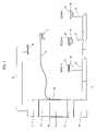
- FIG. 1is a block diagram of a typical forced air residential HVAC system.
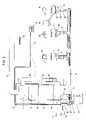
- FIG. 2is a high-level block diagram of the present invention installed in the HVAC system illustrated in FIG. 1 .
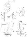
- FIG. 3illustrates inflatable air bladders used as airflow control devices.
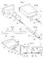
- FIG. 4illustrates the method for mounting a bladder in an air duct.
- FIG. 5is a cross section drawing of one air valve of a plurality of servo controlled air valves.
- FIG. 6is a cross section drawing of two blocks of air valves and connecting air-feed tee.
- FIG. 7is a perspective drawing of the valve servo.
- FIG. 8is a cross section drawing of the valve servo positioned over one of the air valves.
- FIG. 9is a perspective drawing of the position servo.
- FIG. 10illustrates the air pump enclosure and its mounting system.
- FIG. 11is a detailed diagram of the pressure and vacuum relief valves.
- FIG. 12illustrates a wireless thermometer device and the thermometer data message.
- FIG. 13illustrates the radio receiver that receives thermometer data messages and the method for measuring signal strength.
- FIG. 14is a schematic diagram of the control processor interface circuit to the existing HVAC equipment.
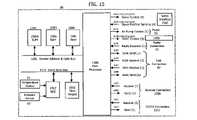
- FIG. 15is a block diagram of the control processor.
- FIG. 16is a schematic diagram of the servo interface circuit.
- FIG. 17is a perspective diagram of the control processor printed circuit board mounted in the main enclosure.
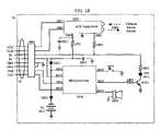
- FIG. 18is a schematic diagram of the IrDA link circuit.
- FIG. 19is a drawing of the IrDA link enclosure installed in an air vent grill.
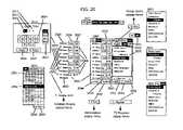
- FIG. 20illustrates the primary display screen of the PDA interface program.
- FIG. 21illustrates the popup menus used to specify a Comfort-Climate.
- FIG. 22illustrates the popup menus used to specify the Group-room menu and used to save and retrieve temperature schedule programs.
- FIG. 23illustrates the popup menus that display HVAC information for each room.
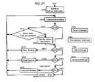
- FIG. 24is a high level flow diagram of the control processor program.
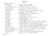
- FIG. 25is a listing of the main data structure used by the control processor program.
- FIG. 26is a flow diagram of the heat, cool, and circulate program routines.
- FIG. 27illustrates the data structures used to store temperature schedule programs.
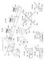
- FIG. 28illustrates the process used to install air tubes in air ducts.
- FIG. 1is a block diagram of a typical forced air system.
- the existing central HVAC unit 10is typically comprised of a return air plenum 11 , a blower 12 , a furnace 13 , an optional heat exchanger for air conditioning 14 , and a conditioned air plenum 15 .
- the configuration shownis called “down flow” because the air flows down.
- Other possible configurationsinclude “up flow” and “horizontal flow”.
- a network of air duct trunks 16 and air duct branches 17connect from the conditioned air plenum 15 to each air vent 18 in room A, room B, and room C. Each air vent is covered by an air grill 31 .
- the inventionis designed for larger houses with many rooms and at least one air vent in each room.
- the conditioned air forced into each roomis typically returned to the central HVAC unit 10 through one or more common return air vents 19 located in central areas. Air flows through the air return duct 20 into the return plenum 11 .
- the existing thermostat 21is connected by a multi-conductor cable 73 to the existing HVAC controller 22 that switches power to the blower, furnace and air conditioner.
- the existing thermostat 21commands the blower and furnace or blower and air conditioner to provide conditioned air to cause the temperature at thermostat to move toward the temperature set at the existing thermostat 21 .
- FIG. 1is only representative of many possible configurations of forced air HVAC systems found in existing houses.
- the air conditionercan be replaced by a heat pump that can provide both heating and cooling, eliminating the furnace.
- a heat pumpis used in combination with a furnace.
- the present inventioncan accommodate the different configurations found in most existing houses.
- FIG. 2is a block diagram of the present invention installed in an existing forced air HVAC system as shown in FIG. 1 .
- the airflow through each ventis controlled by an airtight bladder 30 mounted behind the air grill 31 covering the air vent 18 .
- the bladderis either fully inflated or deflated while the blower 12 is forcing air through the air duct 17 .
- a small air tube 32( ⁇ 0.25′′ OD) is pulled through the existing air ducts to connect each bladder to one air valve of a plurality of servo controlled air valves 40 mounted on the side of the conditioned air plenum 15 . There is one air valve for each bladder.
- a small air pump in air pump enclosure 50provides a source of low-pressure ( ⁇ 1 psi) compressed air and vacuum at a rate of ⁇ 1.5 cubic feet per minute.
- the pressure air tube 51connects the pressurized air to the air valves 40 .
- the vacuum air tube 52connects the vacuum to the air valves 40 .
- the air pump enclosure 50also contains a 5V power supply and control circuit for the air pump.
- the AC power cord 54connects the system to 110V AC power.
- the power and control cable 55connect the 5V power supply to the control processor and servo controlled air valves and connects the control processor 60 to the circuit that controls the air pump.
- the control processor 60controls the servos in 40 to set each air valve to one of two positions. The first position connects the compressed air to the air tube so that the bladder inflates. The second position connects the vacuum to the air tube so that the bladder deflates.
- thermometer 70is placed in each room in the house. All thermometers transmit on a shared radio frequency of 433 MHz packets of digital information that encode 32-bit digital messages.
- a digital messageincludes a unique thermometer identification number, the temperature, and command data. Two or more thermometers can transmit at the same time, causing errors in the data. To detect errors, the 32-bit digital message is encoded twice in the packet.
- the radio receiver 71decodes the messages from all the thermometers 70 , discards packets that have errors, and generates messages that are communicated by serial data link 72 to the control processor 60 .
- the radio receiver 71can be located away from the shielding effects of the HVAC equipment if necessary to ensure reception from all thermometers.
- the control processor 60is connected to the existing HVAC controller 22 by the existing HVAC controller connection 74 .
- the control processor 60 interface circuituses the same signals as the existing thermostat 21 to control the HVAC equipment.
- the existing thermostat connection 73is also connected to the control processor 60 interface circuit that includes a manual two position switch. In the first switch position, the HVAC controller 22 is connected to the control processor 60 . In the second switch position, the HVAC controller is connected to the existing thermostat 21 .
- the existing thermostat 21is retained as a backup temperature control system.
- the control processor 60controls the HVAC equipment and the airflow to each room according to the temperature reported for each room and according to an independent temperature schedule for each room.
- the temperature schedulesspecify a heat-when-below-temperature and a cool-when-above-temperature for each minute of a 24-hour day. A different temperature schedule can be specified for each day for each room.
- These temperature schedulesare specified by the occupants using a interface program operating on a standard PDA (personal data assistant) 80 . PDAs are available from several manufacturers such as Palm.
- PDAspersonal data assistant
- the interface programprovides graphical screens and popup menus that simplify the specification of the temperature schedules and the assignment of schedules to rooms for the days of the week and for other special dates.
- the PDA 80includes a standard infrared communications interface called IrDA that is used to communicate with the control processor 60 .
- the IrDA link 81is mounted in the most convenient air vent 18 behind its air grill 31 .
- the IrDA link 81has an infrared transmitter and receiver mounted so that it can communicate with the PDA 80 using infrared signals though the air grill.
- the IrDA link 81is connected to the control processor 60 by the link connection 82 that is pulled through the air duct with the air tube to that air vent. After changes are made to the temperature schedules, the PDA 80 is pointed toward the IrDA link 81 and the standard IrDA protocol is used to exchange information between the PDA 80 and the control processor 60 .
- the IrDA link 81also has an audio alarm and light that is controlled by the control processor 60 .
- the control processorcan sound the alarm and flash the light to get the attention of the house occupants if the zone control system needs maintenance.
- the PDA 80is used to communicate with the control processor 60 to determine specific maintenance needs.
- the present inventioncan set the bladders so that all of the airflow goes to a single air vent, thereby conditioning the air in a single room. This could cause excessive air velocity and noise at the air vent and possibly damage the HVAC equipment.
- Thisis solved by connecting a bypass air duct 90 between the conditioned air plenum 15 and the return air plenum 11 .
- a bladder 91is installed in the bypass 90 and its air tube is connected to an air valve 40 so that the control processor can enable or disable the bypass.
- the bypassprovides a path for the excess airflow and storage for conditioned air.
- the control processor 60is interfaced to a temperature sensor 61 located inside the conditioned air plenum 15 .
- the control processormonitors the conditioned air temperature to ensure that the temperature in the plenum 115 does not go above a preset temperature when heating or below a preset temperature when cooling, and ensures that the blower continues to run until all of the heating or cooling has been transferred to the rooms. This is important when bypass is used and only a portion of the heating or cooling capacity is needed, so the furnace or air conditioner is turned only for a short time. Some existing HVAC equipment has two or more heating or cooling speeds or capacities. When present, the control processor 60 controls the speed control and selects the speed based on the number of air vents open. This capability can eliminate the need for the bypass 90 .
- a pressure sensor 62is mounted inside the conditioned air plenum 15 and interfaced to the control processor 60 .
- the plenum pressure as a function of different bladder settingsis used to deduce the airflow capacity of each air vent in the system and to predict the plenum pressure for any combination of air valve settings.
- the airflow to each room and the time spent heating or cooling each roomis use to provide a relative measure of the energy used to condition each room. This information is reported to the house occupants via the PDA 80 .
- FIG. 3is a diagram showing the construction of the bladders 30 used airflow control devices.
- the bladdersare constructed of flexible thin plastic or fabric coated with an airtight flexible sealer. The material is approved by UL or other listing agency for use in plenums.
- the bladders for controlling airflow in round air ductsare cylinders made by seaming together two circular shapes 301 and a rectangular shape 302 . Depending on the material, the airtight seams are heat sealed or glued. The material is only slightly elastic so the inflated size is determined by the dimensions of these shapes.
- An air tube connector 310is sealed to the rectangular shape 302 .
- the air tube connectoris molded from flexible plastic approved for use in plenums.
- FIG. 3Ashows more detail of the air tube connector 310 , which has an air tube socket 312 sized so that it tightly grips the outside of the air tube 32 .
- the air tube connectorprovides the air path from the air tube to the inside of the bladder.
- the air tube connectoris contoured to match the curvature of the round air duct and has a notch 311 to fit a mounting strap. This shape prevents conditioned air from leaking around the bladder when it is inflated.
- the inflated bladder 303is about 110% the diameter of the air duct and its height is about 75% of the diameter. When inflated in the duct, the cylinder wall is pressed firmly against the inside of the air duct, effectively blocking all airflow.
- the deflated bladder 304presents a small cross-section to airflow and restricts airflow by less than 10%.
- the standard round duct sizes connecting to air vents in residential installationsare 4′′, 6′′, and 8′′.
- Bypass 90can be 6′′, 8′′, or 10′′ in diameter. A total of only 4 different round duct bladder sizes are needed for residential installations.
- the bladders for controlling airflow in rectangular ductsare also cylinders made by seaming together two circular shapes 321 and a rectangular shape 322 .
- the cylinderis oriented so that the axis of the cylinder is parallel to the widest dimension of the duct.
- the height of the cylinderis about 110% of the wider dimension of the duct.
- the cylinder diameteris at least 110% of the narrower dimension of the duct, but can be as much as 200%.
- FIG. 3Bshows more detail of the air tube connector 330 , which is contoured for the flat surface of the rectangular duct and it has a notch 331 to fit a mounting strap and air tube socket 332 sized to fit the outside of the air tube 32 .
- FIG. 4shows several views of the method for mounting the bladder 30 in an air duct 17 at and air vent 18 covered by air grill 31 .
- the air tube 32is inserted into the air tube socket 312 in the air tube connector 310 sealed to the bladder 30 shown with the top portion cut away.
- Mounting clamp 402compresses the air tube socket around the air tube.
- FIG. 4Cis a plain view of the mounting strap, which is made form thin metal (18 gage) and is approximately 1′′ by 12′′.
- Hole 407is used to secure the air tube to the mounting strap.
- One pair of holes 406are used to secure the mounting clamp 402 to the mounting strap.
- Two of the holes 408are used to secure the mounting strap to the inside of the air vent or air duct at the air vent.
- FIG. 4Dis a perspective drawing showing the mounting clamp 402 connecting to the mounting strap 401 .
- the mounting clampstraddles the air tube socket 312 (shown in FIG. 4E ) and two bladder clamp screws 405 pass through holes 406 in the mounting strap and screw into the mounting clamp.
- Several pairs of holes 406are provided so the bladder can be positioned for the most effective seal of the air duct.
- the screws 405are self-tapping with flat heads that match counter-sinks pressed into the holes 406 in the mounting strap.
- Tightening the bladder clamp screws 405cause the bladder clamp 402 to compress the air tube socket 312 firmly around the air tube 32 , securing the bladder to the mounting strap and ensuring an air tight seal between the air tube and the bladder.
- the screw headsare flat with the bottom surface of the mounting strap, and the mounting strap fits in the notch 311 of the air tube connector 310 so the mounting strap is flat with the air tube connector.
- FIG. 4Fis a cross section view of the assembled bladder installed in an air duct 17 connecting to air vent 18 covered by air grill 31 .
- the air tube 32is secured to the mounting strap 401 by the air tube clamp 403 (also shown in FIG. 4D ) using a screw 409 and nut through hole 407 (shown in FIG. 4C ).
- the air tube clamptransfers any tension on the air tube to the mounting strap and prevents strain on the connection between the air tube and the bladder.
- the mounting clamp 402is connected to the mounting strap by two screws 405 and compresses the air tube socket 312 and secures the bladder 30 to the mounting strap.
- the mounting strapis secured to the inside of the air duct or air vent by two screws 404 through holes 408 (shown in FIG. 4C ).
- Some air ventsare constructed with in integrated section of air duct several inched long, which fits inside the connecting air duct 17 .
- the inflated bladdercan make contact with this extension of the air vent or it can make contact in the air duct when the extension is not part of the air vent.
- FIG. 4Ais an exploded perspective view of the assembled bladder 30 and mounting strap 401 fitting into the air duct 17 connected to air vent 18 .
- the inside of the air duct or air vent 410 where the bladder makes contactmust be a smooth surface. If sharp sheet metal edges or screws are present, they are cut or smoothed and covered with duct mastic or duct tape to form a smooth surface and contour.
- FIG. 4Bis an exploded perspective view of an assembled bladder and air tube secured to amounting strap 401 for mounting inside a rectangular air duct 411 .
- the air grillis removed and an air tube 32 is pulled from the air vent to the plenum 15 .
- the air tubeis secured to the mounting strap 401 and the proper size and shape bladder 30 is secured to the mounting strap.
- the inside surface 410 of the air vent or air ductis prepared by smoothing, cutting, or covering sharp edges and screws. In many cases, no preparation is required. This surface is chosen so it is close enough to the front of the air vent to provide convenient access for any surface preparation work.
- the mounting strapis inserted into the air vent and the mounting strap is bent and position so the inflated bladder meets the surface 410 .
- the mounting strapis then secured to the inside of the air vent by one or two sheet metal screws.
- the air grillis then reinstalled. After installation, the bladder is hidden by the air grill, and there are no visible signs of installation. The installation requires no other modification to the air duct, air vent, or air grill, and no other access to the air duct is required.
- FIG. 5shows several views of one air valve of a plurality of servo controlled air valves 40 .
- the preferred embodimenthas two valve blocks made of plastic using injection molding. Each valve block is approximately 1′′ ⁇ 2′′ ⁇ 7′′ and contains valve cylinders for 12 valves.
- FIG. 5Ais a cross section view of one valve block 501 sectioned through one of the valve cylinders 502 .
- Each valve cylinderis 0.375′′ in diameter and approximately 1.875′′ deep.
- Each valve cylinderhas three holes ( ⁇ 0.188′′) that connect the cylinder to the pressure cavity 503 , the valve header 504 (shown in cross section), and the vacuum cavity 505 .
- the valve header 504connects the air tube 32 (shown in full view) to the valve cylinder and provides one side of the pressure and vacuum cavities in the valve block.
- the valve headeris made of plastic using injection molding and is glued to the valve block to form airtight seals.
- the air tube 32is press fit into the air tube hole 506 in the valve header.
- the inside of the air tube holehas a one-way compression edge 507 making it difficult to pull the air tube from the header after it has been inserted.
- the valve blockis mounted on a side of the conditioned air plenum 15 so that the portion of valve header 504 connecting to the air tube is inside the plenum and the portion of the valve header sealing the pressure and vacuum cavities and the valve block 501 are outside the plenum.
- FIG. 5Cis a perspective view of the valve slide 510 and FIG. 5D is a top view of the same valve slide.
- the valve slidehas groves for O-ring 511 and O-ring 512 .
- the valve slidehas a valve lever 514 that protrudes above the valve plate 515 . The valve lever is used to move the valve slide inside the valve cylinder.
- FIG. 5A and FIG. 5Brepresent the same air valve in two different positions.
- the valve slide 510(shown in full view) fits snugly inside the valve cylinder 502 so that the O-rings seal the cavities formed by the cylinder wall and the valve slide.
- the slide valvehas two resting positions, the pressure position 520 shown in FIG. 5B and the vacuum position 521 shown in FIG. 5A .
- the air pump 50is turned on only when the valves are in one of these two positions. The air pump is off while the valves are moved. Referring to FIG. 5B , when the slide valve is in the pressure position 520 , O-ring 511 seals the vacuum cavity and the valve cylinder from the air tube.
- the cavity formed between O-ring 511 and O-ring 512connects the pressure cavity to the air tube so pressurized air will flow through the air tube to inflate the bladder.
- O-ring 512seals the valve cylinder from the outside air. Referring to FIG 5 A, when the slide valve is in the vacuum position 521 , the vacuum cavity is connected to the air tube and O-ring 511 seals the vacuum cavity from the pressure cavity. The bladder is deflated as air flows through the air tube towards the vacuum created by the air pump. O-ring 511 and O-ring 512 seals the pressure cavity from the air tube and outside air. The valve slide is moved to either the pressure position 520 or the vacuum position 521 by a servo that engages the valve lever 514 .
- FIG. 5Eshows an end view of a valve slide as positioned when in a valve cylinder.
- the valve lever 514 and valve plate 515are constrained from rotating about the valve cylinder axis by a slot 516 in the valve constraint 513 .
- the valve constrainthas a slot 516 for each valve slide.
- FIG. 5Aalso shows a side view of the valve plate 515 and the valve constraint 513 .
- FIG. 6shows several views of the two valve blocks 601 and 602 and air-feed tee 603 .
- FIG. 6Ais a cross-section view through the axis of the valve cylinders of valve block 601 and valve block 602 positioned so that the valve slides 510 (shown in full view) are interleaved. Interleaving minimizes the spacing between valve slides and aligns the valve levers 514 so the valve servo can move the valve slides in valve blocks 601 and 602 . Some of the valve slides are shown in the pressure position and the others are shown in the vacuum position.
- the valve constraint 513has 24 slots 516 that engage the 24 valve slide plates to prevent rotation of the valve slide about the valve cylinder axis.
- the ends of the valve blocks 601 and 602have passageways from the pressure and vacuum cavities to the air-feed tee 603 . O-rings 606 seal the connections between the air-feed tee and these passageways.
- FIG. 6Bis an end cross-section view through the section line shown in FIG. 6A of the passageways in the valve blocks 601 and 602 to the pressure cavities 503 and vacuum cavities 505 .
- the air-feed tee 603is shown in full view.
- Four O-rings 606seal the air-feed tee to the valve blocks.
- the air-feed teehas a vacuum connection 604 that connects to the vacuum air tube 52 and a pressure connection 605 that connects to the pressure air tube 51 .
- the valve levers 514protrude beyond the surface of the valve blocks.
- FIG. 6Dis a top view of the air-feed tee 603 and O-rings 606 in isolation from the valve blocks.
- FIG. 6Cis a cross-section view (through the section line shown in FIG. 6E ) of the air-feed tee and the vacuum connection 604 .
- FIG. 6Eis a front view of the air-feed tee in isolation.
- FIG. 6Fis a cross-section view (through the section line shown in FIG. 6D ) of the air-feed tee through the center of the passageways connecting to the pressure and vacuum cavities.
- FIG. 7is a perspective drawing of the valve servo 700 .
- the servo carriage 701is made of injection molded plastic.
- the servo carriageis supported by the position threaded rod 702 and the slide rod 703 .
- the position threaded rodis 3 ⁇ 8′′ in diameter and has 16 threads per inch.
- the servo carriagehas a position threaded bearing 704 that engages the position threaded rod.
- the position threaded bearingmay be a threaded hole machined in the valve carriage plastic, or may be a threaded metal cylinder press fit into a hole in the servo carriage. The fit between the position threaded rod and the position threaded bearing is loose so there is minimum friction as the threaded rod rotates to move the servo carriage.
- the interface between the threaded rod and the threaded bearingprovides support and constraint for the servo carriage for all directions except rotation about the axis of the threaded rod.
- Rotation constraintis provided by the smooth slide rod 703 that engages the carriage guide 705 .
- the fit between the slide rod and the carriage guideis loose so there is minimum friction as the carriage is moved by rotation of the position threaded rod.
- the servo carriagehas a bearing post 710 and a bearing plate 711 that support the two valve bearings 712 .
- the valve bearingsare press fit into holes molded in the bearing post and bearing plate.
- the valve threaded rod 713is a standard #8 sized screw with 32 threads per inch. The ends of the valve threaded rod are machined to fit the valve bearings so the rod can rotate with minimum friction and constrained so it can not move in any other way.
- the valve drive spur gear 714is approximately 1′′ in diameter and is fastened to the end of the valve threaded rod.
- the valve motor 720is mounted on the bearing plate 711 by two screws 721 (one screw 721 is hidden by spur gear 714 ) that pass through the bearing plate into the end of the motor.
- the valve motor spur gear 722is approximately 3/16′′ in diameter and is fastened to the shaft of the valve motor.
- the valve motoris positioned so that the valve motor spur gear engages the valve drive spur gear.
- the valve motoroperates on 5 volts DC using approximately 0.3 A. It rotates CW or CCW depending on the direction of current flow.
- the control processor 60has an interface circuit that enables it to drive the valve motor CW or CCW at full power.
- the controlis binary on or off.
- the valve motor, valve motor spur gear, and valve drive spur gearare chosen so that the valve threaded rod rotates approximately 1000 RPM when the valve motor is driven.
- the servo slider 730has a slider threaded bearing 731 that engages the valve threaded rod 713 .
- the servo slideris supported by the valve threaded rod and is constrained by the threaded rod in all directions except rotation about the axis of the threaded rod.
- the servo sliderpasses through the slider slot 732 in the servo carriage.
- the slider slotconstrains the servo slider so that as the valve threaded rod rotates, the servo slider can only move parallel to the axis of the slot and the axis of the valve threaded rod. The fit between the servo slider and the slider slot is loose to minimize friction as the slider moves.
- the bearing post 710 and bearing plate 711also support the valve PCB (printed circuit board) 740 .
- the valve PCBconnects to a 6-conductor flat flexible cable 706 that connects to the interface circuit of the control processor 60 .
- Two wires from the valve motorconnect to PCB 740 and to two conductors in the flexible cable.
- the valve PCBsupports the A-photo-interrupter 741 and the B-photo-interrupter 742 .
- the photo-interruptersare positioned so that A-slider tab 743 and B-slider tab 744 on the servo slider 730 pass through the photo-interrupters as the servo slider is moved by the valve motor and valve threaded rod.
- the photo-interruptersgenerate binary digital signals that encode three positions of the of the servo slider. These digital signals are connected to the control processor through the flexible cable and are used by the control processor when driving the valve motor to position the servo slider.
- FIG. 8shows three views of the valve servo positioned over the valve blocks.
- FIG. 8Ashows the valve blocks 601 and 602 in cross-section with the valve servo 700 positioned over one of the valve slides 510 in valve block 602 .
- the positions of the valve servois established by the position threaded rod 702 , position threaded rod bearing 704 , slide rod 703 , and carriage guide 705 .
- the servo slider 730is shown in the center position 800 .
- A-slider finger 810 and B-slider finger 811have about 1/16′′ clearance from any of the valve levers 514 in either the pressure position 520 or the vacuum position 521 . Both valve sliders are shown in the vacuum position.
- the A-photo-interrupter 741 and the B-photo-interrupter 742are positioned so that neither the A-slider tab 743 nor the B-slider tab 744 interrupt the light path in the photo-interrupters when the servo slider is in the center position 800 . This is the only position where both photo-interrupters are uninterrupted.
- FIG. 8Bshows the servo slider in the B-position 801 corresponding to the pressure position 520 of the valve slide.
- the B-slider tab 744interrupts the A-photo-interrupter 741 while the light path of the B-photo-interrupter is uninterrupted.
- both photo-interruptersare interrupted by the B-slider tab.
- the control processordrives the valve motor until the light path of the B-photo-interrupter is uninterrupted.
- the valve motor directionis reversed and driven until both photo-interrupters are uninterrupted.
- FIG. 8Cshows the servo slider in the A-position 802 corresponding to the vacuum position 521 of the valve slide.
- the A-slider tab 743interrupts the B-photo-interrupter 742 while the light path of the A-photo-interrupter 741 is uninterrupted.
- both photo-interruptersare interrupted by the A-slider tab.
- the control processordrives the valve motor until the light path of the A-photo-interrupter is uninterrupted.
- the motor directionis reversed and driven until both photo-interrupters are uninterrupted.
- valve servoWhen the control processor begins operation, the position of valve servo is unknown, and must be initialized.
- the valve servois initialized first by testing the signals from the A- and B-photo-interrupters. If both are uninterrupted, then the valve servo is in the center position 800 and properly initialized. Any other combination of signals from the photo-interrupters represents one of two possible positions.
- both photo-interruptersare interrupted, then either the A-slider tab 743 or the B-slider tab 744 is interrupting the light paths.
- the servo slideris driven towards the B-position 801 until the B-photo-interrupter becomes uninterrupted.
- the servo slidereither is in the B-position or is just right of the center position. After a pause for the valve motor to come to a stop, the servo slider is driven towards the B-position again. If the A-photo-interrupter becomes uninterrupted within a short time, the servo slider is in the center position, and the valve servo is initialized. If the A-photo-interrupter remains interrupted, then the servo slider is jammed in the B-position and must be driven towards the A-position until both photo-interrupters are uninterrupted.
- the servo slidereither is in the B-position 801 or is slightly right of the center position. The servo slider is driven towards the B-position and if the A-photo-interrupter becomes uninterrupted within a short time, the servo slider is in the center position, and the valve servo is initialized. If the A-photo-interrupter remains interrupted, then the servo slider is jammed in the B-position and must be driven towards the A-position until both photo-interrupters are uninterrupted.
- the servo slidereither is in the A-position 802 or is slightly left of the center position. The servo slider is driven towards the A-position and if the B-photo-interrupter becomes uninterrupted within a short time, the servo slider is in the center position, and the valve servo is initialized. If the B-photo-interrupter remains interrupted, then the servo slider is jammed in the A-position and must be driven towards the B-position until both photo-interrupters are uninterrupted.
- FIG. 9is a perspective drawing of the position servo 900 assembled with valve block 601 and valve block 602 .
- the position bearings 904 and 905are press fit into holes in the motor bracket 902 and bearing bracket 903 .
- the position threaded rod 702is machined to fit in the bearings and to constrain the threaded rod so that the only possible movement is rotation.
- the threaded rodis also machined so that the rotation cam 907 can be fastened to the end that protrudes beyond position bearing 905 and so that the position spur gear 906 can be fastened to the end that protrudes beyond position bearing 904 .
- the slide rod 703is press fit into holes in the motor bracket and the bearing bracket.
- the bearing holes and the slide rod holesare positioned so that the position threaded rod and the slide rod are parallel to each other and to the valve blocks.
- the position threaded bearing 704 of the valve servo 700engages the position threaded rod and the carriage guide 705 engages the slide rod 703 .
- the position motor 910is attached with two screws 912 to the motor plate 911 , which is injection molded as part of the motor bracket 902 .
- the position motoris positioned so that the position worm gear 913 engages the position spur gear 906 .
- Motor bracket 902is attached to the valve block using screws.
- the motor brackethas molded spacers in line with the screw holes so that when attached, the motor bracket is perpendicular to the valve blocks and spaced so that the servo slider can be positioned over the air valve closest to the motor bracket.
- bearing bracket 903is attached to the valve blocks using screws 921 .
- the bearing brackethas molded spacers in line with the screw holes so that when attached, the bearing bracket is perpendicular to the valve blocks and spaced so that the servo slider can be positioned over the air valve closest to the bearing bracket.
- the bearing brackethas a cutout at the bottom center so that the pressure air tube 51 and the vacuum air tube 52 can be attached to the air-feed tee 603 .
- the combination of the motor bracket, bearing bracket, and valve bank 601 and 602 connected together with screwsform a rigid structure that is mounted as a single unit.
- the position motoroperates on 5 volts DC using approximately 0.5A. It rotates CW or CCW depending on the direction of current flow.
- the control processor 60has an interface circuit that enables it to drive the position motor CW or CCW at full power.
- the controlis binary on or off.
- the EOT (end of travel) photo-interrupter 930is mounted on the bearing bracket 903 so that the carriage guide 705 interrupts the light path when the valve servo is positioned over the valve slide 510 closest to the bearing bracket.
- the binary digital signal from the EOT photo-interrupteris interfaced to control processor 60 .
- the rotation photo-interrupter 931is mounted on the bearing bracket 903 and is positioned so that the rotation cam 907 interrupts the light path about 50% of the time as the position threaded rod rotates. For 1 ⁇ 2 of a rotation, the light path is interrupted and is uninterrupted for the other part of a rotation.
- the binary digital signal from the rotation photo-interrupteris interfaced to control processor.
- the position of the valve servo carriageis unknown and must be initialized. If the EOT photo-interrupter is uninterrupted, the position servo is driven to move the valve servo carriage towards the bearing bracket until the EOT photo-interrupter's light path is interrupted by the carriage guide. The EOT photo-interrupter is positioned so that when the position motor stops, the servo slider 730 is positioned over the valve slide closest to the bearing bracket. If the EOT photo-interrupter is initially interrupted, the exact position of the valve servo carriage is not known. Therefore, the position servo is driven to move the valve servo away from the bearing bracket until the EOT photo-interrupter is uninterrupted. Then the position servo is driven to move the valve servo towards the bearing bracket until the EOT photo-interrupter is interrupted, just as if the EOT photo-interrupter was initially uninterrupted.
- the control processorcan set the air valves by controlling the position and valve motors. Beginning with the air valve closest to the bearing bracket, the control processor moves the servo slider to either the A-position or the B-position to set the valve slider to the pressure position or the vacuum position. Then the servo slider is returned to the center position. Then the position servo is driven to move the valve servo so it is positioned over the second air valve.
- the position threaded rodhas 16 threads per inch and the valve slides are spaced 1 ⁇ 4′′ center to center. Therefore, four revolutions of the threaded rod move the valve servo a distance equal to the distance between adjacent valve slides.
- the control processormonitors the rotation photo-interrupter 931 while the position threaded rod rotates, counting the number of transitions from interrupted to uninterrupted. After four such transitions, the position motor is stopped. Then the valve servo is drive to set the next valve, and after returning to the center position, the position motor drives the position threaded rod for four more revolutions. This cycle is repeated until all 24 valves are set.
- the preferred embodiment of the servo controlled valvesrequires less then one minute to set the positions of all 24 air valves.
- valve servoAfter twenty-four air valves are set, the valve servo is positioned over the air valve closest to the motor bracket. The next time the valves are set, the position servo moves the valve servo toward the bearing bracket. The valve servo position is reinitialized by using the EOT photo-interrupter to set the position for the air valve closest to the bearing bracket. This ensures any errors in counting rotations are corrected every other cycle of setting air valves.
- FIG. 10is a perspective the air pump enclosure 50 and its mounting system.
- the air pump 1020has a vibrating armature that oscillates at the 60 Hz power line frequency.
- the preferred embodimentuse pump model 6025 from Thomas Pumps, Sheboygan, Wis. It produces noise that could be objectionable in some installations.
- the air pumpis attached to the enclosure base 50 A by four shock absorbing mounting posts 1010 .
- the enclosure baseis further isolated by using shock absorbing wall mounts 1011 .
- the enclosure base and enclosure cover 50 Bare made of sound absorbing plastic to further isolate the noise.
- the enclosure coverhas multiple small ventilation slots 1012 .
- the pump PCB (printed circuit board) 1001 and the 5V DC power supply 1002are fastened to the enclosure base 50 A.
- the pump PCBhas a standard optically isolated triac circuit that uses a 5V binary signal from the control processor 60 to control the 110V AC power to the air pump.
- the pump PCBalso has terminals to connect the 100V AC power cord 54 , the AC supply to 5V power supply 1003 , the 5V power from the supply 1004 , and the controlled AC supply to the air pump 1005 .
- the 3-conductor power and control cable 55connects to the pump PCB by connector 1006 .
- the pressure and vacuum produced by the air pumpare unregulated.
- a pair of diaphragm relief valves 1000 made from injected molded plasticare use to limit the pressure and vacuum to about 1 psi.
- the relief valvesare connected to the air pump by flexible air tubes 1007 to provide noise isolation.
- the relief valvesconnect to the pressure air tube 51 and the vacuum air tube 52 .
- FIG. 11shows several views of the relief valves 1000 .
- FIG. 11Ais a cross-section view through the section line shown in FIG. 11C .
- the main valve structure 1100is a cylinder made of injection molded plastic.
- a plate 1101divides the cylinder into a pressure cavity 1102 and a vacuum cavity 1103 .
- the vacuum feed tube 1104passes through pressure cavity and an air passage 1106 connects it to the vacuum cavity.
- the pressure feed tube 1105passes through the vacuum cavity and an air passage 1107 connects it to the pressure cavity. This arrangement enables the pressure feed tube 1105 and the vacuum feed tube 1104 to connect to the ports of the air pump with short and straight tubes.
- a thin plastic diaphragm 1110is glued to the rim of the relief valve structure 1100 .
- the diaphragmhas a hole in the center that is covered by the pressure plug 1111 .
- a threaded stud 1112is mounted in the center of the divider 1101 , and the pressure plug is threaded to match the stud. Turning the pressure plug CW or CCW decreases or increases the force between the plug and the diaphragm, thus adjusting the relief pressure.
- a thin plastic diaphragm 1120is glued to the rim of the relief valve structure 1100 .
- the diaphragmhas a hole in the center that is covered by the vacuum plug 1121 .
- a threaded stud 1112is mounted in the center of the divider 1101 , and the vacuum plug is threaded to match the stud. Turning the vacuum plug CW or CCW increases or decreases the force between the plug and the diaphragm, thus adjusting the relief pressure.
- FIG. 11Bis a full end view of the cross-section view shown in FIG. 11A .
- FIG. 11Cis a bottom view of the relief valves.
- the pressure air tube 51connects to the pressure air feed 1105 B and the pressure air feed 1105 A connects to a flexible air tube 1007 that in turn connects to the pressure output of the air pump 1020 .
- the vacuum air tube 52connects to the vacuum feed tube 1104 B and the vacuum feed tube 1104 A connects to a second flexible air tube 1007 that in turn connects to the vacuum input of the air pump.
- FIG. 11Dis a cross-section view through the section line shown in FIG. 11B of the pressure cavity 1102 .
- Air passage 1107connects the pressure feed tube 1105 to the cavity.
- Air passage 1106connects the vacuum feed tube 1104 to the vacuum cavity 1103 .
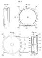
- FIG. 12Ais a perspective view the wireless thermometer 70 that is placed in each room.
- the thermometeris approximately 2′′ ⁇ 3′′ by 3 ⁇ 4′′ and is powered by two AA batteries. The batteries are accessed through a snap-on cover on the back.
- Mounting bracket 1201is attached to a vertical surface using a screw through hole 1202 or adhesive. The thermometer has a matching recess that slides into the mounting bracket. When mounted, the thermometer is flush with the mounting surface.
- the mounting bracketcan also be used to mount the thermometer under a horizontal surface such as a table, or the thermometer can be placed on a horizontal surface. Since there are no connecting wires, the thermometer can be placed in any convenient location in the room. Placing the thermometer near the occupants produces the most comfortable results.
- the LCD (liquid crystal display) 1200 of the wireless thermometeris comprised of several display areas.
- the temperature display 1203shows the current temperature in degrees Fahrenheit at the thermometer.
- the thermometerhas a “Warm” push button 1204 , a “Cool” push button 1205 , and a “N/S” push button 1207 that are used to enter control commands that are transmitted to the control processor 60 where the commands are executed. The actual behavior of the commands is determined by parameters set in the control processor.
- One set of commandsspecifies temporary temperature changes in the room controlled by the thermometer.
- the local temperaturecan be increased or decreased by discrete amounts.
- the preferred embodimentprovides two levels of “warmer” (+2 and +4 degrees) and two levels of “cooler” ( ⁇ 2 and ⁇ 4 degrees).
- the display area 1206displays none or only one of the commands “Warm”, “Warmer”, “Cool”, “Cooler”.
- the commandsare selected by pushing the button 1204 or 1205 . When no commands are active, all elements of display 1206 are turned off. Pushing the “Warm” button causes the “Warm” element of display 1206 to turn on. Pushing the “Warm” button a second time causes the “Warmer” element to turn on and the “Warm” element to turn off.
- thermometerWhen a temperature command is entered, the thermometer sends the command to the control processor, and the control processor controls the HVAC equipment to cause the temperature change.
- the thermometerstores the temperature when the command was entered.
- the thermometerturns off the display 1206 and the command is cancelled.
- the temperature commandis temporary to compensate for unusual comfort conditions.
- the roomis allowed to return to the temperature specified in its temperature schedule.
- a second command entered from the thermometerchanges the complete temperature schedule program for the room, a group of rooms, or the whole house.
- the PDA 80is used to specify the temperature schedule programs and to associate a “Normal” temperature schedule program and a “Special” temperature schedule program to each thermometer. By default, the “Normal” and “Special” programs are the same, so the change schedule command has no effect.
- a change schedule commandis entered by pressing the “N/S” 1207 push button, which toggles the display area 1208 so that either “Normal” or “Special” is on. For example, if “Normal” is on, pushing the “N/S” push button turns on “Special” and turns off “Normal”. Each additional push toggles the display.
- thermometerOnly one thermometer need be programmed for this behavior. Other thermometers can be programmed to switch schedules that affect only their assigned room.
- thermometerstransmit on the same radio channel at 433 Mhz using 100% AM modulation to send binary data.
- Full signal strengthrepresents a binary “one” and the absence of a signal represents a binary “zero”.
- Self-clocking, phase-shift Manchester codingis used to send the data message bit-serially.
- a “one”-“zero” sequencerepresents a data bit value of “1” and a “zero”-“one” sequence represents a data bit value of “0”.
- a data packetis composed of a fixed pattern of “one”s and “zero” s followed by 32-bits of encoded data followed by a repeat of the same fixed pattern and the same 32-bits of encoded data.
- a complete packetrequires about 0.3 seconds to transmit.
- thermometerWhile the 32-bit data remains constant, the thermometer transmits packets at an average rate of one packet per 120 seconds. When the 32-bit data changes, the thermometer transmits at an average rate of one packet per 15 seconds for three minutes. After the 32-bit data is stable for 3 minutes, the average rate is reduced to one packet per 120 seconds. Each thermometer transmits an average of 0.3/120 ⁇ 0.25% of the time when the data is unchanged and 0.3/15 ⁇ 2% of the time for 3 minutes after the data has changed. Although the average time between transmissions is 15 seconds or 120 seconds, each thermometer uses a different pseudorandom process to determine the specific time between successive transmissions. This “randomizes” the transmissions to ensure an equal probability for each thermometer that the shared radio channel is clear when it transmits a packet.
- thermometers sharing the same radio channelWith 20 thermometers sharing the same radio channel about 80%–90% of the packets are received without errors.
- the transmission range in a houseis about 100 feet, so systems in adjacent houses may interfere, but thermometers in houses further away will not interfere. Even with 80 thermometers sharing the same radio channel, sufficient packets are received error free to enable the present invention to operate. If necessary, other channels in the 433 Mhz band can be used to enable more thermometers to operate in the same area.
- FIG. 12Bshows the function of each bit in the 32-bit data message 1230 .
- the first bit transmittedis called bit- 1 and the last bit is called bit- 32 .
- Bit- 1 through bit- 8is the ID (identification).
- the thermometer IDranges from 0 to 255 and is determined by switch settings inside the thermometer and assigned at installation to a specific room.
- Bit- 9 through bit- 20encodes the centigrade temperature as three digits.
- a 4-bit BCD (binary coded decimal) codeis used to specify digits 0 through 9.
- Bit- 9 through bit- 12encodes BCD 0 representing 0.1 degree centigrade
- bit- 13 through bit- 16encodes BCD 1 representing 1 degree centigrade
- bit- 17 through bit- 20encodes BCD 2 representing 10 degrees centigrade.
- Bit- 21encodes the temperature sign so the total range is ⁇ 99.9 to 99.9. Although the data is transmitted in centigrade temperature units, the display and other aspects of the present invention use Fahrenheit temperature units.
- Bit- 22is set to “1” if the batteries are low.
- Bit- 25 through bit- 28encode the temperature commands “Cooler”, “Cool”, “Warm”, and “Warmer”.
- Bit- 29is set to “0” if the “Normal” temperature schedule is selected. Bit- 29 is set to “1” if the “Special” temperature schedule is selected.
- Bit- 30is set to “0” when the slow transmission rate (1 packet per 120 seconds) is used. Bit- 30 is set to “1” when the fast transmission rate is used (1 packet per 15 seconds).
- Bit- 31is set to “1” for 10 minute following a schedule change command (“N/S” button). Bit- 31 is set to “0” all other times.
- FIG. 13Bis a perspective view of the radio receiver 71 . It is enclosed in a small plastic box approximately 1′′ ⁇ 1.5′′ ⁇ 3′′ with an adjustable antenna 1300 on one end.
- the receiveris mounted to a wall or ceiling using a screw through mounting hole 1301 . It is connected to the control processor by a 4-conductor flat telephone wire 72 using a standard RJ-45 plug and jack 1302 . Two conductors are used for the 5V and ground supply and one conductor is used to send serial data to the control processor 60 .
- FIG. 13Ais a schematic diagram of the radio receiver 71 . It is comprised of a standard commercial 433 Mhz integrated receiver module 1310 with attached antenna 1311 .
- the receiverhas a digital output 1312 that decodes the presence of a signal as “one” and the absence of a signal as “zero”.
- the digital outputis connected to input 1314 of programmable microprocessor 1313 .
- the microprocessoris part number PIC12C508 manufactured by Microchip Technology Inc., Chandler Ariz.
- the microprocessoris programmed to decode the phase-shift Mchester coding, compare the two 32-bit data messages and if identical, send a bit-serial data message through output 1315 to the control processor via the cable 72 .
- the receivermust be placed so that data packets from all thermometers are received reliably.
- the radio receivermeasures the signal strength of each received packet and encodes a measure of the signal strength as an 8-bit value.
- the receiver modulehas an analog output 1316 that is amplified by a standard op-amp 1320 .
- the op-ampis an LM358 manufactured by National Semiconductor, Santa Clara Calif.
- the ratio 13 R 2 / 13 R 1 of resistors 13 R 1 and 13 R 2is selected so that the peak-to peak output 1321 of the op-amp is about 1 ⁇ 2 full scale (2.5V) for a signal of acceptable strength.
- the resistors 13 R 3 and 13 R 4bias the op-amp so its output is about 2 ⁇ 3 full scale (3.3V).
- Diode 13 D 1 in combination with resistor 13 R 5 and capacitor 13 C 1form a peak detector and filter for the signal 1321 .
- the 13 R 5 * 13 C 1 time constantis about 100 microseconds.
- the peak detectoris connected to input 1325 of the microprocessor. Input 1325 has a threshold voltage of about 2 volts, so the microprocessor reads “1”, if the voltage is above 2 volts and reads “0” if the voltage is below 2 volts.
- the microprocessorsets output 1322 to “1” (5V) when receiving packets and the input 1325 follows the peak signal. Since the output of the op-amp is biased above the threshold of the 1325 input, the microprocessor will always read “1” while receiving data. When the microprocessor receives a valid 32-bit message, the output 1322 is set to “0” (0V). This causes the op-amp output to be 0V and the peak detector discharges towards 0V with a time constant of 13 R 5 * 13 C 1 .
- the microprocessordigitally encodes the peak signal strength by measuring the time it takes for the digital input 1325 to cross the threshold so the microprocessor reads “0”.
- FIG. 13Cis a voltage versus time graph for four signals.
- Graph 1330illustrates a strong signal at op-amp output 1321 and the corresponding peak detector voltage graph 1331 at the microprocessor input 1325 . For this case, it requires time t 2 for signal 1331 to cross the 2V threshold.
- the voltage graph 1332shows a weak signal and voltage graph 1333 shows the corresponding peak detector signal. For this case, it requires time t 1 for signal 1333 to cross the 2V threshold.
- the microprocessorcontinuously adds “1” a counter while testing the input 1325 . When 1325 becomes “0”, the value of the counter is the measure of the signal strength.
- the digital output 1322is then set to “1” so the peak detector again tracks the strength of the received signal.
- the 8-bit encoded value for the signal strength and the 32-bit data message received from the thermometerare sent to the control processor as five 8-bit bytes using a standard serial UART protocol at 1200 bits per second.
- the signal strength informationis used during installation to ensure each signal has sufficient strength to be reliable and also monitored during operation for maintenance purposes.
- FIG. 14is a diagram of the control processor 60 interface circuit 1400 to the existing HVAC controller 22 and existing thermostat 21 .
- the interface circuitprovides for four independent control signals called “Heat”, “Blower”, “Cool”, and “Auxiliary”.
- the present inventionrequires an HVAC system that has at least two controls: “Heat” and “Blower” or “Cool” and “Blower”. Many residential HVAC systems have three controls: “Heat”, “Blower”, and “Cool”. Some residential HVAC systems are more complex and use a fourth control.
- the present inventionprovides an “Auxiliary” control that may be used for different purposes.
- “Auxiliary”can control the second speed of a two-speed blower, the second heating level of a two-level furnace, or the heating or cooling function of a heat pump used with a furnace.
- Standard residential HVAC controllersprovide a common low voltage (36V) AC supply that turns on the HVAC equipment when a connection is made between the common supply and the corresponding HVAC control input. Connections can be made using dry contact switches or solid-state switches.
- the present inventionretains the existing thermostat for back up control.
- the multi-wire existing thermostat connection 73is cut and both ends are spliced to wires that connect to the interface 1400 .
- the corresponding existing HVAC controller wiresare connected to terminals 14 T 1 for “Heat”, 14 T 2 for “Blower”, 14 T 3 for “Cool”, 14 T 4 for “Auxiliary”, and 14 T 5 for common AC supply from the HVAC controller.
- the corresponding existing thermostat wiresare connected to terminals 14 T 11 for “Heat”, 14 T 12 for “Blower”, 14 T 13 for “Cool”, 14 T 14 for “Auxiliary”, and 14 T 15 for common AC supply from the HVAC controller.
- Switch 1405is a four-pole, double-throw slide switch shown in the position that connects the control processor to the existing HVAC controller. When switch 1405 is in the other position, the existing thermostat is connected to the existing HVAC controller.
- Each solid-state switch 1401 through 1404is comprised of an optoisolator triac driver 1420 connected to the control gate of triac 1421 .
- One power terminal of the triacis connected to the common supply 14 T 5 from the existing HVAC controller.
- the other power terminal of the triacis connected to a control signals such as “Heat” 14 T 1 of the existing HVAC controller.
- the optoisolatoris connected to the common supply by resistors 14 R 2 to provide the reference voltage for the triac gate signal.
- the triacis protected from high voltage spikes by the bypass path through resistor 14 R 3 and capacitor 14 C 1 .
- the control signal 1410 from the control processor 60connects to the input of optoisolator triac driver 1420 .
- Resistor 14 R 1limits the current used by the optoisolator when driving the triac.
- the control signalis “1” (5V)
- no currentflows through 14 R 1 , the triac is off, and the HVAC equipment is off.
- the control signalis “0” (0V)
- currentflows through 14 R 1 and the optoisolator, the triac, and the HVAC equipment are on.
- FIG. 15is a block diagram of the control processor 60 .
- the control processoruses standard components and standard design practices well known to those skilled in the art.
- the main processor 1500is part number MC68332 manufactured by Motorola, Austin, Tex.
- the parallel address and data bus 1501connects the processor to a 256 kb (kilobyte) ROM 1502 (read only memory) that contains the program, a 32 kb SRAM 1503 (static random access memory) used during execution, and a 1 Mb (megabyte) flash memory 1504 used to store house specific data, temperature schedules, and records of the temperatures and HVAC activity.
- a 256 kb (kilobyte) ROM 1502read only memory
- 32 kb SRAM 1503static random access memory
- 1 Mb (megabyte) flash memory 1504used to store house specific data, temperature schedules, and records of the temperatures and HVAC activity.
- the serial data bus 1510connects to a timekeeper circuit 1511 comprised of an integrated circuit timekeeper, a 32 kHz crystal, and a watch battery.
- the integrated circuitis part number DS1302 manufactured by Dallas Semiconductor, Dallas, Tex. (now a wholly-owned subsidary of Maxim Integrated Products, Inc., Sunnyvale, Calif).
- the timekeeper circuitoperates continuously, independent of the main processor, using a dedicated crystal and backup battery when the main processor is not powered.
- the timekeepercomputes the current time of day with one-second resolution, the day of the week (1–7), the month (1–12), the day of the month (1–31), and the year (00–99), properly accounting for leap years.
- the main processorcan set or read the time and date at any time using the serial data bus.
- the serial data bus 1510connects to a multi-channel 12-bit resolution ADC (analog-to-digital converter) 1512 .
- the ADCencodes the analog signal from the plenum temperature sensor 61 and the analog signal from plenum pressure sensor 62 .
- the ADCis a TSC2003 manufactured by Texas Instruments
- the temperature sensoris a LM135 manufactured by STMicroelectronics, Carlton, Tex.
- the pressure sensoris an MPXM2010 manufactured by Motorola, Austin, Tex.
- the pressure sensor output signalis amplified by a factor of 100 using a conventional op-amp circuit before conversion by the ACD.
- the main processoruses the serial bus to command the ADC to encode the pressure sensor or the temperature sensor. After a delay for the ADC to encode the signal, the main processor reads the encoded value using the serial bus.
- the main processorhas a plurality of programmable digital input and output signals used to control and monitor the components of the present invention.
- the valve motor 720 and position motor 910are controlled by the four servo control signals 1521 , 1522 , 1523 , and 1524 .
- the photo-interrupters 741 , 742 , 930 , and 931are monitored by the servo position sensing signals 1525 , 1526 , 1527 , and 1528 .
- the servo interfaces 560has drivers for the valve and position motors and circuits to condition the signals from the photo-interrupters.
- the air pump 1020is controlled by the air pump control signal 1529 and connected to the air pump by the power and control connection 55 .
- the HVAC equipment “Heat” 1410 , “Blower” 1411 , “Cool” 1412 , and “Auxiliary” 1413are controlled by the HVAC control signals 1530 , 1531 , 1532 , and 1533 that are connected to the HVAC interface circuit 1400 .
- the radio receiver 71is connected to the radio receiver signal 1534 by the radio connection 72 .
- the IrDA send signal 1535is connected to IrDA link 81 by link connection 82 .
- the IrDA link 81is connected by link connection 82 to the IrDA receive signal 1536 .
- the alert receive signal 1537 and alert send signal 1538are also connected to IrDA link 81 by link connection 82 .
- the preferred embodimenthas provisions to control residential houses that have two or more independent HVAC systems.
- the remote receive signal 1539 and the remote send signal 1540are connected by remote connection 1550 to a remote processor that controls the remote HVAC equipment, the servo controlled air valves, and measures the plenum temperature and pressure in the remote HVAC system.
- the remote systemdoes not have a radio receiver 71 or an IrDA link 81 .
- the main processorcommunicates using the RS232 serial connection 1551 with a lap top computer used to configure and calibrate the system.
- the connection 1551connects to the RS232 receive signal 1541 and the RS232 send signal 1542 .
- the RS232 interfacecan also be used during operation to monitor system behavior or provide remote communications and control via a telephone modem or Internet connection.
- FIG. 16is a schematic diagram of the servo interface 1560 .
- the circuit 1600is the driver interface for the position motor and identical circuit 1640 is the driver circuit for the valve motor.
- Signals 1521 and 1522control the position motor 910 and signals 1523 and 1524 control the valve motor 720 . These signals are in a high impendence state when the main processor 1500 is first started.
- resistor 16 R 1connected to 5V through resistor 16 R 2 ensures that PNP transistor 16 TR 1 is not conducting and that the input to inverter 1610 is “1” so its output is “0”, ensuring that NPN transistor 16 TR 2 is not conducting.
- transistors 16 TR 3 and 16 TR 4are not conducting.
- transistor 16 TR 1is biased to conduct and the output of inverter 1610 becomes “1”, causing transistor 16 TR 2 to conduct.
- transistor 16 TR 3is biased to conduct and the output of inverter 1611 is “1”, so transistor 16 TR 4 is biased to conduct.
- Signals 1521 and 1522are never both “0” at the same time.
- Signals 1523 and 1524control the output signals 1641 and 1642 so that the valve motor 720 is driven CW when signal 1523 is “0” and is driven CCW when signal 1524 is “0”.
- Circuit 1620includes the photo-interrupter 930 that is connected to the main processor signal 1525 .
- Resistor 16 R 8limits the current through the light emitting diode connected to 5V.
- Resistor 16 R 7provides the load for the phototransistor so that when the light path is uninterrupted, the phototransistor conducts and the signal 1525 is “1”. When the light path is interrupted, the phototransistor does not conduct, and signal 1525 is “0”.
- the circuits 1630 , 1650 , and 1660 for photo-interrupters 931 , 741 , and 742are identical to 1620 and function in the same way to produce signals 1526 , 1527 , and 1528 .
- FIG. 17is an exploded perspective view of the system components that are mounted on the plenum 15 .
- the control processor 60 and interface circuitsare built on a PCB (printed circuit board) 1700 approximately 5′′ ⁇ 5′′, which is mounted to the main enclosure base 1701 .
- the PCBincludes the terminals and sockets used to connect the control processor signals to the servo controlled air valves 40 , the power and control connection 55 , the temperature sensor 61 , the pressure sensor 62 , the radio receiver connection 72 , the existing thermostat connection 73 , the existing HVAC controller connection 74 , the IrDA link connection 82 , the RS232 connection 1551 , and the remote connection 1550 .
- Side 1703 of the main enclosure base 1701has access cutouts and restraining cable clamps 1702 for the power and control connection 55 , the radio connection 72 , the existing thermostat connection 73 , the existing HVAC controller connection 74 , the RS232 connection 1551 , and the remote connection 1550 (when used).
- the main enclosure base 1701has a cutout sized and positioned to provide clearance for the valve header 504 on the valve block 601 and valve block 602 .
- the servo controlled air valve 40 as shown in FIG. 9is mounted to the main enclosure base 1701 .
- the main enclosure basealso has cutouts for the pressure and temperature sensors to access the inside of the plenum and for the link connection 82 to pass from the plenum to its connector on the PCB 1700 .
- the PCBis mounted above the air valve blocks.
- Side 1703also has cutouts for the pressure air tube 51 and vacuum air tube 52 connected to the air-feed tee.
- the main enclosure top 1710fits to the base 1701 to form a complete enclosure. Vent slots 1711 in the main enclosure top provide ventilation. A cutout 1712 in the main enclosure top matches the location of switch 1405 on PCB 1700 so that when the main enclosure top is in position, the switch 1405 can be manually switched to either position.
- a hole 1720 approximately 16′′ ⁇ 16′′is cut in the side of the conditioned air plenum 15 .
- the holeprovides access for the process used to pull the air tubes 32 and to provide access when attaching the air tubes.
- the material removed to form the holeis made into a cover 1730 for the hole by attaching framing straps 1722 , 1723 , 1724 , and 1725 to 1730 .
- the framing strapsare made from 20-gauge sheet metal approximately 2′′ wide.
- the mounting strapshave mounting holes 1726 approximately every 4′′ and 1 ⁇ 4′′ from each edge and have a thin layer of gasket material 1727 attached to one side.
- the strapsare cut to length from a continuous roll, bent flat, and attached to the hole-material using sheet metal screws 1728 through the holes along the inside edge of the framing straps so that the framing straps extend approximately 1′′ beyond all edges of the hole-material. For clarity, only the screws used with framing strap 1722 are shown.
- a rectangular hole is cutis the cover 1730 sized and positioned to match the cutouts in the bottom of the main enclosure base 1701 that provide clearance for the air valve headers and clearance for the pressure and temperature sensors and the link connection.
- the main enclosure baseis fastened to the cover.
- the coveris attached to plenum using sheet metal screws through the holes along the outer edge of the framing straps.
- the gasket material on the mounting strapsseals the mounting straps to the plenum and the cover 1730 .
- FIG. 18is a schematic diagram of the IrDA link 81 circuit.
- the link connection 82is a plenum rated Category 5, 8-conductor cable that connects to the IrDA link by a RJ-54 plug and socket combination 1800 .
- Two conductorscarry 5V power from the control processor to the IrDA link, two conductors are used to return power ground, and four conductors are used for signals connected to the control processor.
- An integrated IrDA transceiver 1801 part number TFDU4100 manufactured by Vishay Telefunken, Heilbronn, Germanyis used to generate and receive infrared digital signals 1804 .
- Resistor 18 R 1 and capacitor 18 C 1decouple the transceiver signal 1804 from power supply noise.
- the IrDA send signal 1535is connected to the transceiver output 1802 by the IrDA connection 82 .
- the current used by the infrared emitteris limited by resistor 18 R 2 connected to LED pin 1805 .
- the received infrared light pulsesare amplified to standard 5V logic “1” or “0” levels to generate the output signal 1803 connected to the IrDA receive signal 1536 by the IrDA connection 82 .
- the alert send 1538 signalis connected to input 1811 of the microprocessor 1810 .
- the microprocessoris a PIC12C508 manufactured by Microchip Technology Inc., Chandler Ariz.
- the microprocessor output 1812is connected to a piezo audio transducer 1820 .
- Microprocessor output 1813drives the base of transistor 18 TR 1 through resistor 18 R 4 so that the transistor conducts when output 1813 is “1”, causing LED (light emitting diode) 1821 to emit light. Current flow through the LED and transistor 18 TR 1 is limited by resistor 18 R 3 .
- the reset push button switch 1814connects “0” (ground) to microprocessor input 1815 .
- the microprocessor output 1819is connected to the alert receive signal 1537 by the IrDA link connection 82 .
- 5V power from the control processoris decoupled by capacitor 18 C 2 and connected to the microprocessor power input 1816 through isolation diode 18 D 1 .
- the 3V backup battery 1817is connected to the microprocessor power input 1816 through isolation diode 18 D 2 .
- the microprocessoris powered by 5V from the control processor, and diode 18 D 2 isolates the power input 1816 from the battery.
- the batteryis isolated from the control processor power supply by diode 18 D 1 and the battery supplies power the to microprocessor.
- the microprocessorcan operate using voltages between 2.5V and 5V.
- the 5V power from the control processoris connected to microprocessor input 1818 so the microprocessor can sense when the control processor is not supplying power.
- the microprocessoris programmed to perform the alert functions specified by 8-bit commands from the control processor.
- the programcan generate an audible tone of various frequencies by periodically inverting the logic level of output 1812 connected to the audio transducer 1820 .
- the LEDcan be flashed at various rates by periodically inverting the logic level of output 1813 .
- Different combinations of tones and LED flashesare used to form different alerts. For example, a “Major Alert” is a continuously changing tone and a fast LED flashing, a “Minor Alert” is a single tone turned on and off for one second periods and a slow flashing LED, and a “Progress Alert” is a sequence of three tones and a single LED flash.
- An alert command from the control processoris sent as an 8-bit byte using a standard UART bit-serial protocol at 1200 bits per second.
- the microprocessor 1810receives and decodes the command byte, and executes its program to generate the appropriate alert.
- a “Major Alert”is used to signal a major problem that needs immediate attention such as a non-functioning furnace.
- a “Minor Alert”is used to signal a minor problem such as a low battery indication from a thermometer.
- a “Progress Alert”is used to signal completion of a task such as establishing communications with the PDA 80 .
- the microprocessoris programmed to perform a “watch dog” function to ensure the control processor is functioning properly.
- One alert commandis called the “I'mOK” command.
- the control processormust send this command to the microprocessor at least every minute. If the microprocessor does not regularly receive the “I'mOK” command, the microprocessor generates the “Major Alert”. Likewise, if the control processor does not supply power, the microprocessor generates the “Major Alert”. The occupant can turn off any alert by pushing the reset button 1814 connected to input 1815 .
- the microprocessorsets the output signal 1819 to “1” when the reset button is pushed. This signals the control processor by signal 1537 that the occupant has acknowledged the alert.
- the control processorcan send an alert command to reset the output 1819 to logic level “0”.
- FIG. 19shows three views of the IrDA link 81 .
- FIG. 19Ais a side view of the IrDA enclosure 1900 installed in an air vent grill 31 .
- the outside surface 1905 of the air grillfaces into the room and is typically flush with a floor, wall, or ceiling.
- FIG. 19Cis a view of the front 1904 of the IrDA link enclosure that secures and provides access to the LED 1821 , the IrDA transceiver 1801 , and the reset push button 1814 .
- FIG. 19Bis an enlarged cut-away view of the IrDA link enclosure 1900 installed in the air vent.
- the enclosureis made of injection molded plastic.
- the IrDA link enclosureis attached to the grill by metal clip 1901 that is placed over a grill louver 1902 and secured by screw 1903 .
- the IrDA enclosureis positioned so that the front 1904 including the LED, IrDA transceiver, and push button are placed facing towards the room slightly below the outside surface 1905 of the air grill. This position allows the IrDA to have line of sight to the PDA 80 , the LED to be visible to the occupant, and the reset push button to be pushed by the occupant.
- the IrDA enclosurehas a battery compartment 1906 that can be accessed without removing the enclosure from the grill.
- the link connection 82connects to the IrDA enclosure using a RJ-45 plug and matching socket on the rear of the enclosure.
- the present inventionincludes an interface program executed by the PDA 80 that is used to specify the temperature schedules applied to each room.
- the interface programcan have many variations and operate on a variety of processors such as a standard PC or processor-display screen device designed specifically for the present invention.
- the processor that executes the interface programcan communicate with the control processor by a variety of wireless or wired methods.
- the described interface programis intended to be an example and not restrictive.
- the interface programdoes not affect any other operation of the PDA, so the PDA can be used for other purposes.
- the PDA display screenis touch-sensitive and a stylus is tapped on the screen or moved on the screen to make selections and enter data. Selections are indicating by an inverted display that shows white areas as black and black areas as white. An object is selected when its display is inverted.
- the interface programfollows the same protocols as other PDA programs so someone familiar with the PDA finds the interface program intuitive and easy to use.
- the standard PDA home menuis used to select the interface program.
- FIG. 20illustrates the primary display screen 2000 of the PDA interface program.
- the display screenis approximately 2′′ ⁇ 2′′ with a resolution of 160 by 160 pixels.
- the temperature schedule 2001displays a 24-hour day beginning at 12:00 am (ref. no. 2002 ) and ending at Midnight 2003 .
- a number of specific times 2004can be specified to divide the day into periods. Specific time are not required, so there may be only one period stretching from 12:00 am to Midnight. There can be as many as seven specific times 2004 so there can be as many as eight periods.
- a “comfort-climate” 2005 for each periodis displayed on the line between the start time and the end time for that comfort-climate.
- the down pointing arrowindicates a popup menu is associated with each comfort-climate.
- Selecting any comfort-climatecauses the “Comfort-Climate” popup menu 2100 to appear, shown in FIG. 21 and described in the following.
- Each comfort-climate displayalso displays a temperature range 2008 . Selecting a temperature range causes the “Edit Comfort-Climate” popup menu 2110 to appear, shown in FIG. 21 and described in the following.
- An “Add” selection 2006 and a “Del” selection 2007is displayed on the same line and following “12:00 am” 2002 , and on the same line and following each time 2004 . Selecting “Add” causes all of the lines of the temperature display below the “Add” selection to be moved down by two lines. Then a new comfort-climate 2005 is added to first line below the “Add” selection, and a new time 2004 is added to the second line below the selected “Add” selection. This sequence of operations adds a complete new period to the 24-hour schedule. When the temperature schedule has more than five periods, the “Midnight” display 2003 is replaced with “More” and the first five periods are displayed.
- Selecting the “More” selection 2003causes the last 5 periods to be displayed, the display 2003 to display “Midnight”, and the display 2002 to display “More”. Selecting the “More” selection 2002 causes the first 5 periods to be displayed. Selecting a “Del” selection 2007 deletes the period immediately below the selection, removing two lines from the temperature schedule display. The portions of the temperature schedule beginning three lines below the “Del” selection and ending with “Midnight” 2003 are moved up by two lines.
- Selecting any of the times 2004causes the “Enter Time” popup menu 2010 to appear.
- the numerical portions of the selected time 2004are displayed by digits 2011 , 2012 , and 2013 .
- Digit 2011is displayed selected when the popup menu first appears. One and only one of these three digits can be selected at any time.
- Display 2014has selections for digits “0”, “1”, . . . “12”. Selecting one of these digits causes the selected digit 2011 , 2012 , or 2013 to be replaced by the digit selected in display 2014 .
- the following digit 2012 , 2013 , or 2011is automatically selected so that sequential selections in display 2014 sequentially enter the digits to specify the time.
- CPYCPY
- PSTCPY selection
- Selecting “CPY”causes the displayed temperature schedule to be copied to memory for storage.
- Selecting “PST”causes the temperature schedule copied by the “CPY” selection to replace the currently displayed temperature schedule.
- the 7-Day display 2020 and the Group-room display 2030are used to display and to select the days and rooms that use the same temperature schedule.
- the 7-Day display 2020has selections “Wk”, “SUN”, “MON”, . . . , “SAT” corresponding to the entire week (“Wk”) and the days of the week Sunday, Monday, . . . , Saturday.
- the displayhas two modes: a “select-mode” and an “edit-mode”.
- the “Sel Edit” selection 2021displays the current mode so that “Sel Edit” indicates select-mode and “Sel Edit” indicates the edit-mode where a bold character corresponds to an inverted display. Selecting “Sel Edit” causes the mode to change to “Sel Edit” so that select-mode becomes edit-mode.
- Selecting “Sel Edit”causes the mode to change to “Sel Edit” so that edit-mode becomes select-mode.
- 7-Day displayis in the select-mode, all days that use the displayed temperature schedule are displayed as selected.
- the temperature schedule for that dayis displayed and all of the other days that use that same schedule are displayed as selected. For example, suppose the TS Program used one set of temperature schedules for weekdays and another set for weekend days. 7-Day display 2020 shows “SUN” and “SAT” selected, so the temperature schedule is used for weekend days. Selecting any of “MON” through “FRI” causes the display 2022 to display “MON” through “FRI” as selected and the weekend days as unselected. The weekday temperature schedule is displayed.
- the 7-Day displayis used to select the days that should use the displayed temperature schedule. Selecting a day changes the selection of that day. If the day is selected, it becomes unselected, if unselected it becomes selected. The temperature schedule does not change when day selections are made in the edit-mode.
- the Group-room display 2030selects groups and rooms. Its function is similar to the 7-Day display.
- the Group-room displayhas a “select-mode” and an “edit-mode” controlled by the “Sel Edit” selection 2021 .
- the 7-Day display and Group-room displayare either both in edit-mode or both in select-mode.
- the Group-room display 2030displays all of the groups and rooms that use different temperature schedules. When in the select-mode, all of the groups and rooms that use the displayed temperature schedule are displayed as selected. Selecting any unselected group or room selects the temperature schedule used by that group or room and all of the groups and rooms that use that temperature schedule are displayed as selected.
- the displayed temperature scheduleis uniquely identified by the 7-Day display 2020 day selections and the Group-room display 2030 group and room selections.
- the PDA interface programautomatically includes in the Group-room display 2030 all of the groups and rooms needed to represent the entire TS Program. If a room is part of a group and does not have a separate set of temperature schedules, then the room is not displayed. It is represented by its group. Typically, most of the rooms are grouped so a typical Group-room display has 3–5 groups and 2–5 rooms that use different temperature schedules.
- Display 2032displays the group “Living Area” with one of its member rooms “Kitchen”. When “Living Area” is selected, the temperature schedule used by all of the rooms in the “Living Area” except “Kitchen” is displayed. When “>Kitchen” is selected as in display 2033 , the temperature schedule used by “Kitchen” is displayed.
- the Group-room displayWhen in the edit-mode, the Group-room display is used to select the groups and rooms that should use the displayed temperature schedule. Selecting a group or room only changes the selection of that group or room. If it is selected, it becomes unselected, and if unselected it becomes selected. The temperature schedule does not change when a group or a room is selected or deselected when in edit-mode.
- selecting the “SAVE” selection 2040saves the displayed temperature scheduled and assigns it to all of the selected groups and rooms in the Group-room display 2030 for all of the selected days in the 7-Day display 2020 .
- the other temperature schedules and assignments in the TS Programare not affected.
- Selecting the “CANCEL” selection 2041discards all of the changes made to the temperature schedule since the last “SAVE” or “CANCEL” selection. Changes made using any of popup menus are not affected. Any change made to the temperature schedule causes the 7-Day and Group-room displays to go to edit-mode. Selecting “SAVE” or “CANCEL” causes the 7-Day and Group-room displays to go to select-mode.
- the temperature schedule display 2001is replaced by display 2050 .
- Each temperature scheduleis represented by a rectangle outlined by a dotted line.
- Display 2051represents each day of the week using the first letter of that day.
- the row of seven temperature schedules used by the selected group or roomis displayed as selected.
- Display 2052displays the 7-day temperature schedule used by the “Master Suite” as selected.
- the Group-room display 2030displays as selected all of groups and rooms that use that identical 7-day temperature schedule.
- Display 2050displays as selected only the one group or room originally selected, while display 2030 displays as selected all groups and rooms that use that 7-day temperature schedule. Any group or room in the Group-room display 2030 can then be selected or deselected. The group or room that was originally selected to specify the 7-day temperature schedule can be deselected. Selecting the “Save” selection 2040 causes the 7-day temperature schedule to be assigned to the groups and rooms selected, causes the mode to become select-mode, and causes display 2050 to be replaced by the normal temperature schedule display 2001 .
- the 7-Day display 2020displays “Wk” as unselected and “SUN” as selected. Other days that use the displayed temperature schedule are displayed as selected.
- selecting the “CPY” selection 2018causes the 7-day temperature schedule used by the selected group or room to be copied to memory. Selecting “CPY” does not change the edit-mode or any of the displays.
- selecting the “PST” selection 2019causes previously copied 7-day temperature schedule to be assigned to all of the groups and rooms selected in the Group-room display 2030 . If a single temperature schedule was previously copied, then that temperature schedule is assigned to all days of the 7-day temperature schedule.
- selecting the “PST” selection 2019causes the mode to become select-mode and causes display 2050 to be replaced by the normal temperature schedule display 2001 .
- the 7-Day display 2020displays “Wk” as unselected and “SUN” as selected. Other days that use the displayed temperature are displayed as selected.
- selecting the “CANCEL” selection 2041discards all changes, causes the mode to become select-mode, and causes display 2050 to be replaced by the normal temperature schedule display 2001 .
- selecting the “Entire House” selection in display 2030causes all of the temperature schedules used during the selected day to be treated as a single entire-house temperature schedule.
- the temperature schedule display 2001is replaced by display 2050 .
- the column of temperature schedules associated with the selected day of the weekis displayed as selected.
- the 7-Day display 2020displays as selected all of days that have an identical entire-house temperature schedule.
- Display 2050displays as selected only the one day originally selected, while display 2020 displays as selected all days that use the same entire-house temperature schedule. Any day in the 7-Day display 2020 can then be selected or deselected.
- the day that was originally selected to specify the entire-house temperature schedulecan be deselected. Selecting the “Save” selection 2040 causes the entire-house temperature schedule to be assigned to the days selected in the 7-Day display 2020 , causes the mode to become select-mode, and causes display 2050 to be replaced by the normal temperature schedule display 2001 .
- the Group-room display 2030displays “Entire House” as unselected and the first group or room as selected. Other groups or rooms that use the displayed temperature schedule are displayed as selected.
- selecting the “CPY” selection 2018causes the selected entire-house temperature schedule to be copied to memory. Selecting “CPY” does not change the edit-mode or any of the displays.
- selecting the “PST” selection 2019causes the previously copied entire-house temperature schedule to be assigned to all of the days selected in the 7-Day display 2020 . If a single temperature schedule was previously copied, then that temperature schedule is assigned to all temperature schedules in the entire-house temperature schedule. A copied 7-day temperature schedule cannot be assigned as an entire-house temperature schedule and a copied entire-house temperature schedule cannot be assigned as a 7-day temperature schedule.
- selecting the “PST” selection 2019also causes the mode to become select-mode and causes display 2050 to be replaced by the normal temperature schedule display 2001 .
- the Group-room display 2030displays “Entire House” as unselected and the first group or room as selected. Other groups or rooms that use the displayed temperature schedule are displayed as selected.
- selecting the “CANCEL” selection 2041discards all changes, causes the mode to become select-mode, and causes display 2050 to be replaced by the normal temperature schedule display 2001 .
- Selecting the “G/Rms” selection 2035causes the “Edit Menu” popup menu 2200 to appear, shown in FIG. 22 and described in the following. This selection is used to add, edit, or delete the groups and rooms displayed in the Group-room display 2030 .
- Selecting the “TS Program” selection 2042causes the “TS Program” popup menu 2220 to appear as shown in FIG. 22 and described in the following. This selection is used to create, retrieve, save, or delete TS Programs or to specify a set of dates when a special TS Program is used.
- Selecting the “INFO” selection 2043causes the “Information” popup menu 2300 to appear as shown in FIG. 23 and described below.
- Selecting the “SYNC” selection 2044causes the PDA 80 to attempt to establish an IrDA communications link with the control processor 60 and exchange information.
- the control processorsends data about HVAC configurations and activity, and maintenance needs to the PDA.
- the PDAsends all of the current TS Program information.
- the control processormaintains the master copy of the TS Programs and the information to initialize and adapt the PDA interface program to the house.
- Several different PDAscan be used in the same home, and the same PDA can be used in different houses, provided the proper password is used.
- the control processorgenerates a unique identification for each data exchange to manage merging changes from multiple PDAs using different versions of the data.
- FIG. 21shows the “Comfort-Climate” popup menu 2100 that appears when a “Comfort-Climate” 2005 is selected.
- the popup menu 2100displays the available “Comfort-Climates” selections 2101 . Selecting a Comfort-Climate causes the popup to disappear and the selected Comfort-Climate to appear in the temperature schedule.
- Each Comfort-Climatehas an “Edit” selection 2102 that when selected, causes the “Edit Comfort-Climate” popup menu 2110 to appear.
- the “Cool When Above This Temperature” display 2113displays the maximum temperature for the Comfort-Climate.
- Each selection of the up arrow 2111causes the temperature display 2113 to increase by one.
- Each selection of the down arrow 2112causes the temperature display to decrease by one. Selecting the temperature display 2113 causes the “Enter Temperature” popup menu 2130 to appear.
- the first digit of the temperature display 2131is displayed as selected.
- the digit keyboard display 2133has ten digit selections “0”, “1”, . . . “9”.
- the digit 2131is set by selecting a digit in display 2133 .
- the second digit display 2132is selected. Digit 2132 is set by selecting a digit in display 2133 . Selecting the “Return” button 2135 causes the popup menu 2130 to disappear and the entered temperature is displayed in display 2113 . Selecting the “Cancel”button 2134 discards any changes and causes the popup menu 2130 to disappear.
- the “Heat When Below This Temperature” display 2116displays the minimum temperature for the Comfort-Climate.
- the temperatureis set using the same process used to set the temperature display 2113 . Selecting the up arrow 2114 increases the temperature, selecting down arrow 2115 to decreases the temperature, and selecting the temperature display 2116 causes the “Enter Temperature” popup menu 2130 to appear.
- the present inventioncan equalize temperatures by using the blower 12 to force unconditioned air to the warmer and cooler rooms.
- the temperaturesare equalized as the return air mixes.
- the “Air Circulation” display 2117provides three options to control circulation: “Off”, “Mid”, and “High”. Circulation is turned off when “Off” is selected.
- the “Mid” selectionturns on circulation when the temperature is more than four degrees above the heat-when-below-temperature or four degrees below the cool-when-above-temperature.
- the “High” selectionturns on circulation when the temperature is more than two degrees above the heat-when-below-temperature or two degrees below the cool-when-above-temperature.
- the present inventioncontrols the noise produced by the HVAC blower by controlling the plenum pressure, and thus the air velocity through air vents and grills.
- the “Quiet as Possible” display 2118has selections “Yes” and “No”. When “Yes” is selected, the minimum plenum pressure is used when the comfort zone is in effect. For example, the Comfort-Climate used during sleep times in bedrooms may select “Yes” option. When “No” is selected, the maximum plenum pressure may be used.
- the name display 2120displays the name of the Comfort-Climate.
- the “Enter Name” popup menu 2140appears with the name displayed in display 2141 .
- the namecan be edited of entered using the standard PDA “graffiti” strokes. Selecting the “Clear” selection 2142 clears the display 2141 so a new name can be entered. Selecting the “keyboard” selection 2143 causes the PDA keyboard popup menu 2150 to appear and the name (if any) from display 2141 to be displayed in display 2151 .
- the nameis edited or entered by selecting letters from the display area 2152 . Selecting the “Done” selection 2153 causes the keyboard popup menu to disappear and the entered name to be displayed in the name display 2141 .
- Selecting the “Cancel” selection 2145cause any changes to be ignored, the “Enter Name” popup menu to disappear, and the name display 2120 is not changed.
- selecting the “Return” selection 2144causes the name popup menu to disappear and the new name to be displayed in the name display 2120 .
- Selecting the “Cancel” selection 2122causes any changes to be discarded and the “Edit Comfort-Climate” popup menu 2110 to disappear. None in display 2100 is changed. Selecting the “Return” selection 2121 saves the changes and causes the popup menu 2110 to disappear. Selecting the “Delete” selection 2123 removes the Comfort-Climate from the display 2100 and the popup menu 2110 to disappear. A popup warning message appears if the deleted Comfort-Climate is used in any TS Program and a substitute Comfort-Climate must be selected before the delete is allowed.
- Selecting the “New” selection 2170 in popup menu 2100creates a new Comfort-Climate.
- the “New Comfort-Climate” popup menu 2160appears with selections copied from the Comfort-Climate that was displayed when “New” was selected.
- the name display 2161is initialized to “No Name”.
- the popup menu 2160is the same as 2110 except for the title and the initialization of the name display 2161 .
- Selecting selection “Return” 2162causes the popup menu 2160 to disappear and the new Comfort-Climate to be displayed in 2101 .
- the heat-when-below-temperature and the cool-when-above-temperaturesare displayed with the Comfort-Climate name.
- Selecting selection “Cancel” 2163aborts the creation of the new Comfort climate and causes the popup menu 2160 to disappear and no changes to be made to 2101 .
- Selecting the “Cancel” selection 2171causes the popup menu 2100 to disappear and all changes to be discarded. This includes adding, editing, and deleting any of the Comfort-Climates. Selecting the “Return” selection 2172 causes the popup menu 2100 to disappear and all changes to be saved.
- FIG. 22shows the “Edit Menu” popup menu 2200 used to edit the Group-room display 2030 .
- the groups and rooms displayed in the Group-room displayare displayed in the 2201 display area. Selecting a group or room causes the “Edit Group/Room” popup menu 2210 to appear.
- the name of the selected group or the name of the selected roomis displayed in the name display 2212 . All of the rooms in the house are displayed in the display area 2211 . If a group was selected, all of the rooms assigned to the group are displayed as selected.
- the rooms assigned to the groupcan be changed by selecting and deselecting rooms in the display 2211 . Selecting the name display 2212 causes the “Enter Name” popup menu 2140 to appear and the group name can be edited.
- a roomwas selected in display 2201 , then that room is displayed as selected in display 2211 , and one-and-only-one room may be selected. Selecting another room causes the name 2212 to display the name of the newly selected room and the previously selected room to be deselected. The room name cannot be edited using the popup menu 2210 . Selecting the “Delete” selection 2213 causes the selected group or room to be removed from the display 2201 and the Group-room display 2030 , and the “Edit Group/Room” popup menu to disappear. Selecting the “Cancel” selection 2214 discards any changes and causes the “Edit Group/Room” popup menu to disappear. Selecting the “Return” selection 2215 saves the changes and causes the “Edit Group/Room” popup menu to disappear.
- Selecting the “New Item” selection 2202causes the “Edit Group/Room” popup menu 2210 to appear with “No Name” displayed in the name display 2212 . None of the rooms in the display 2211 is displayed as selected. Selecting a room causes its name to appear in the name display 2212 . Selecting the “Return” selection 2215 causes the popup menu 2210 to disappear and the selected room to be added to the display 2201 and the Group-room display 2030 . If two or more rooms are selected, a new group is created and given the default name “New Group” displayed in 2212 . If the name “New Group” is already in use, a number is added to make the name unique: “New Group 2 ”, . . . etc. Selecting the name display 2212 causes the “Enter Name” popup menu 2140 to appear and the group name can be edited.
- Selecting the “Cancel” selection 2203causes all of the changes to be discarded and the “Edit Menu” popup menu 2200 to disappear.
- the Group-room display 2030is unchanged.
- Selecting the “Return” selection 2204causes the display 2201 to be copied to the Group-room display and the “Edit Menu” popup to disappear.
- FIG. 22shows the “TS Program” popup menu 2220 that appears when the display 2042 is selected.
- Display 2221is the default TS program “ ⁇ Normal>” that cannot be renamed or deleted.
- Display 2222displays all of the TS programs available for selection.
- a “Full Prog”specifies the temperature schedule for all rooms for every day of the week.
- a “Part Prog”specifies the temperature schedules for some of the rooms and/or some of the days of the week.
- a “Schedule”is a single temperature schedule with no room or day specification.
- An existing TS Programis edited by selecting it in display 2222 .
- the temperature display 2001is replaced with display 2050 .
- the rows and columnsare displayed as selected to indicate the type of the selected TS Program. If the TS Program has type “Full Prog”, then all 7-day temperature schedule rows and entire-house temperature schedule columns are displayed as selected. If the TS Program has type “Part Prog” then only the rows and columns stored in the program are displayed as selected. If the TS Program has type “Schedule”, then none of the rows and columns are displayed as selected. Selecting any part of display 2000 causes display 2050 to be replaced by temperature schedule display 2001 and the 7-Day display and Group-room display to enter select-mode.
- the selected TS Programis viewed and edited as previously described. Selecting the “Save” selection 2040 saves all changes to the TS Program displayed in display 2042 . If the TS Program has type “Part Prog” or “Schedule”, selecting “Save” does not alter the days or rooms specified by the program.
- TS Programs of type “Part Prog” and “Schedule”can overwrite portions of another TS Program.
- the “TS Program” popup menu 2220displays a “Paste” selection 2223 for each TS Program of type “Part Prog” and “Schedule”. Selecting a “Paste” selection 2223 causes the selected TS Program to overwrite portions of the TS Program being edited and causes the popup menu 2220 to disappear.
- TS Programsonly the temperature schedules for the specified rooms and days associated with the “Part Prog” are overwritten.
- type “Schedule” TS Programsonly the currently displayed temperature schedule is overwritten. Selecting “Paste” 2223 does not change the TS Program name displayed in TS Program display 2042 .
- Selecting the “New Prog” selection 2225creates a new TS program.
- the “Edit Program” popup menu 2230appears and the name display 2231 displays “New TS Program”. Selecting the name display 2231 causes the “Enter Name” popup menu 2140 to appear and the default TS Program name can be edited.
- Display area 2232has selections to specify the program type. One and only one of the three “Yes” selections can be made. Selecting the “Yes” selection associated with “Save as Schedule” sets the program type to “Schedule”. Selecting the “Yes” selection associated with “Save as Full Program” sets the program type to “Full Prog”. No information is needed from the 7-Day display or Group-room display.
- a type “Part Prog” TS Programhas any combination of individual 7-day temperature schedules and/or entire-house temperature schedules.
- the current selections in the 7-Day display 2020 and the Group-room display 2030specify the 7-day and entire-house temperature schedules to save.
- Each group or room selected in the Group-room display 2030causes its 7-day temperature schedule to be saved in the TS Program.
- Each day selected in the 7-Day displaycauses its entire-house temperature schedule to be saved in the TS Program. If no day is selected in display 2020 , the temperature schedule display 2001 is displayed as blank, and only 7-day temperature schedules are saved. If no groups or rooms are selected, the temperature schedule display 2001 is displayed as blank, and only entire-house temperature schedules are saved.
- Selecting the “Return” selection 2235creates the TS Program as specified by the various selections and the popup menu 2230 disappears.
- the display 2222displays the newly created TS Program.
- Selecting the “Cancel” selection 2234discards any changes and the popup menu 2230 disappears. No changes are made to the display 2222 .
- “Modify Program” selection 2224is used to modify existing TS Programs.
- the ⁇ Normal> TS Programcannot be modified.
- the TS Program displayed by display 2042is modified by selecting the display 2042 , which causes the “TS Program” popup menu 2220 to appear.
- Selecting the “Modify Program” selection 2224causes the “Edit Program” popup menu 2230 to appear.
- Selecting the “Delete” selection 2233deletes the TS Program from memory, removes the TS Program from the display 2222 , sets display 2042 to “ ⁇ Normal>”, and causes the popup 2230 to disappear.
- the program type and the program namecan be changed by making selections in the same way as described in the preceding for creating a new TS Program.
- Selecting the “Cancel” selection 2234discards all changes and the popup menu 2230 disappears.
- Selecting the “Return” selection 2235saves the changes and causes the popup 2230 to disappear.
- a TS Programcan be associated with a set of dates.
- the TS Programis only used for the specific dates associated with that TS program.
- Display 2229shows a TS Program associated with the dates “13–19 January”.
- the TS Programis known by the dates and has no other name. Selecting the “New Date” selection causes the “Edit Date” popup menu 2240 to appear. Selecting the “Modify Program” selection 2224 also causes the “Edit Date” popup menu 2240 to appear if the TS Program displayed in display 2042 is associated with a set of dates.
- the date display 2241displays an alphanumeric abbreviation of the currently selected dates.
- the month-year display 2242displays the selected month and year of the monthly calendar display 2248 .
- Each selection of the right arrow 2243causes the calendar to advance by one month.
- Each selection of the left arrow 2244causes the calendar to go back one month.
- Each selection of the down arrow 2245causes the calendar to advance by 7 days.
- the calendarthen spans two months and the display 2248 displays the days of both months.
- Each selection of the up arrow 2246causes the calendar to go back 7 days.
- Display 2247displays the abbreviations for the days of the week. Any combination of dates can be selected in the monthly calendar display 2248 .
- the styluscan be dragged across the calendar to select consecutive dates.
- the date display 2241is changed as dates are selected and deselected.
- Display 2249provides selections “Save as Partial Program” and “Save as Full Program” to select the TS Program type. (A “Schedule” type program cannot be associated with a date.) These TS Program type selections function as described in the proceeding for creating new TS Programs.
- Selecting the “Delete” selection 2250deletes the TS Program from memory, removes it from the display 2222 , causes the display 2042 to display “ ⁇ Normal”>, and causes the popup 2240 to disappear. Selecting the “Cancel” selection 2251 discards all changes and the popup menu 2240 disappears. Selecting the “Return” selection 2252 saves the changes and causes the popup 2240 to disappear.
- the new or modified TS Programis displayed in display 2222 .
- FIG. 23shows the “Information” popup menu 2300 that appears when the “INFO” selection 2043 is selected.
- the popup menudisplays the “Entire House” selection 2302 and selections for each of the rooms 2301 . Selecting a room or the Entire House causes the “Information” popup menu 2310 to appear.
- the displayhas an information display 2313 that displays the information provided by the control processor about the minimum and maximum temperatures, the average energy used, and the average number of hours spent each day heating, cooling, and circulating air for the selected room.
- Display 2312labels the columns of data for the past day (“Day”), week (“Wk”), month (“Mo”), and year (“Yr”). Selecting the name display 2311 causes the “Enter Name” popup menu 2140 to appear and the room name can be edited.
- Selecting the “Select Special Program” selection 2314causes the “Select Special Program” popup menu 2320 to appear.
- This menucontains all of the TS Programs that can be assigned to the “N/S” button 1207 on the thermometer assigned to the room. Selecting a TS program causes the popup menu to disappear and the TS program is displayed in the special schedule display 2314 .
- This TS Programis used when “Special” is selected at the Thermometer. Selecting ⁇ Normal> as the Special Program disables the “N/S” button since ⁇ Normal> is assigned to both selections. Selecting the “Return” selection 2332 cause the popup menu 2320 to disappear and the display 2314 is not changed.
- Selecting the “Cancel” selection 2315discards the selections and the popup menu 2310 disappears.
- Selecting the “Return” selection 2316saves the selections and causes the popup 2310 to disappear.
- Selecting the “Cancel” selection 2303discards all changes and causes the popup menu 2300 to disappear.
- Selecting the “Return” selection 2304saves the selections and causes the popup 2300 to disappear.
- FIG. 24is a high level flow diagram of the program executed by the control processor 60 to control the HVAC equipment and the temperatures in each room.
- the initialization routine 2401sets all variables and components to known initial conditions and four interrupt processes are initialized and enabled to interrupt.
- the timer interrupt 2405uses the processor's internal timekeeper to provide programmable delays of less of a second used when controlling the valve motor and position motor.
- the thermometer interrupt 2402is used to buffer the serial data from the radio receiver 71 .
- the IrDA interrupt 2403is used to communicate with the PDA 80 .
- the remote interrupt 2404is used to communicate with remote HVAC equipment or another computer during installation or when reporting information. Interrupts are disabled only while driving the position and valve motors and while servicing interrupts. Data collected while processing an interrupt is stored and a software flag is set. The interrupt flags are tested during common processing 2410 , the data is processed, and the flags are cleared.
- FIG. 25is a listing of the definition of the data structure written in the C programming language.
- An array of structures named “zone”is declared so that each zone has a unique instance of the memory structure. All routines in the program can read and write any element in any structure using the name “zone[index].element”. For example, zone[2].T[1] is used to read or write the number 1 element in the “T” array of integers in the number 2 instance of the zone data structure.
- the programexecutes an infinite loop with major branching controlled by state variable STATE that can have one of the following values: IDLE, HEAT, COOL, or CIRCULATE.
- the loopbegins with common routines 2410 that are executed every pass through the loop. Examples of common routines are reading the timekeeper 1511 , processing data from the thermometer radio receiver 71 , processing the temperature schedules from the PDA 80 to set the heat when below temperatures (zone[i].HtoTemp) and cool when above temperatures (zone[i].CtoTemp) for all rooms, and recoding data for energy use analysis.
- the state specific routinesare executed.
- STATEis set to HEAT, COOL, or CIRCULATE, and a secondary state variable STATE 2 is set to zero.
- the values for kare calibrated during the installation process.
- the plenum pressure while blower 12 is runningis measured for each of a number of different combinations of enabled air vents. If there are n k's to determine, about 4n different combinations are used, selected so that each air vent is enabled about the same name number of times over the 4n measurements. Then a standard iterative numerical process is used to find the set of values for the k's that produce plenum pressure predictions that best match the set of measured values.
- the value of k 0is different when heating and cooling. This is calibrated by measuring the plenum pressure when heating and when cooling with a fixed set of air vents enabled, and then scaling the respective values of k 0 so the predicted plenum pressure matches the measured values. After calibration, the predicted plenum pressure is typically accurate within +/ ⁇ 5% of the measured plenum pressure.
- the calibrated k i 'sare closely related to the airflow capacity of each air vent. Therefore, when any combination of air vents are enabled, the portion of the total airflow going through the j th air vent is k j /(sum(if on( k i ))). This is closely related to the portion of the energy used to condition the room associated with the j th air vent during a cycle of HVAC conditioning. Accumulating these portions for 24-hours for each air vent and for each HVAC cycle, and scaling by the total time of the HVAC cycles produces an accurate daily estimate of the percentage of energy used to condition each room.
- the position motor and the valve motorare driven by routine 2412 to set all of the air vales to their proper pressure or vacuum position. This takes less than a minute.
- the common processing 2410is not done while setting the air valves, but interrupts are enabled and processed between the times when the motors are driven.
- a control variable START — TIMEis set to the current time read from the timekeeper 1511 , the air pump 50 is turned on.
- STATEis tested by 2420 , and if equal to HEAT, the heat routine 2413 is executed.
- STATEis tested by 2421 , and if equal to COOL, the cool routine 2414 is executed.
- STATEis tested by 2422 , and if equal to CIRCULATE, the circulate routine 2415 is executed.
- STATEis set to IDLE by routine 2416 . This should never happen, but it ensures the loop continues if an error occurs.
- FIG. 26is a flow diagram of the heat, cool, and circulate routines. Each is adapted to control the appropriate HVAC equipment according to the needs of the equipment.
- routine 2601causes a delay equal to VALVE — TIME (about 30 seconds) to allow the bladders to inflate before turning on the blower 12 .
- “Time”represents the current time read from the timekeeper 1511 . While the current time is less than START — TIME+VALVE — TIME, nothing is changed and the loop starting with common processing 2410 is repeated.
- STATE 2is set to 1, the appropriate HVAC equipment and blower is turned on, and START — TIME is set to the current time, and the loop is repeated.
- routine 2603is executed. While the current time is less than START — TIME+DURATION, the HVAC equipment provides conditioning and routine 2604 is executed.
- Routine 2604uses the plenum temperature senor 61 to measure the plenum temperature sensor.
- the furnace (or other heat source) 13is turned off while blower 12 remains on. Circulation continues so that the plenum temperature decreases. After the plenum cools sufficiently, the heat is turned on.
- the cool routine 2414when the plenum temperature is less than the minimum, the air conditioner (or other cooling source) 14 is turned off while blower 12 remains on. Circulation continues so that the plenum temperature increases. After the plenum warms sufficiently, the cooling is turned on.
- the HVAC equipmentis turned off and STATE 2 is set to 2.
- the plenum temperature and pressure checksare not used, so STATE is set to IDLE and the blower is turned off.
- the heat routine 2413circulation is continued until the plenum temperature is close to normal room temperature to ensure that most of the heat is transferred to the rooms. Then the blower is turned off and the plenum pressure monitored until it becomes zero. This ensures that the furnace controller is not continuing to run the blower.
- STATEis set to IDLE.
- FIG. 27is illustrates the data structures used to store the information specified in the PDA 80 using the interface program and transferred to the control processor 60 .
- Information in these data structuresare processed by the common processing 2410 to set the heat when below temperature and cool when above temperature for each room for each minute of each day.
- Each data structurehas an 8-bit “Name Index” that corresponds to one of the names in the Names 2710 data structure.
- a namecan be any combination of ASCII characters up to 20 characters long.
- the Active TS Program 2700 “Name Index”specifies the currently active TS program.
- the TS Programs 2702 data structureis identified by its “Name Index”. Any number of TS Programs can have the same “Name Index”. All TS Programs with their “Name Index” equal to the Active TS Program “Name Index” are processed. “Rooms” is a 32-bit binary number that specifies the rooms that use this TS Program. The first bit corresponds to the room assigned to the first instance of the zones data structure shown in FIG. 25 . Each successive bit in “Rooms” corresponds to successive zone instances. The bit is set to “1” if the TS Program is used by its corresponding room. The PDA 80 interface program assures that one of the Active TS Programs is used by the entire house, so all of the bits in “Rooms” are set to “1”. The Other Active TS Programs may have any number of “Rooms” bits set to “1”.
- the TS Programhas a “Temperature Schedule Index” for each day of the 7-day cycle.
- the “Temperature Schedule Index”specifies an instance in the array of Temperatures Schedules 2705 data structures.
- Each Temperature Schedulehas eight pairs of “Time” and “Comfort-Climate Index” values. The first pair specifies the Comfort-Climate in use from 12:00 am until the first “Time”. The second pair specifies the comfort zone in use from the first “Time” until the second “Time” and so on.
- the “Comfort-Climate Index”specifies an instance in the array of Comfort-Climate 2703 data structures.
- Each Comfort-Climate data structurehas values corresponding to parameters that can be specified for the Comfort-Climates using the “Edit Comfort-Climate” popup menu 2110 shown in FIG. 21 .
- “Heat When Below Temperature” and “Cool When Above Temperature”are used by routine 2411 to control the conditioning of each room.
- the Special Dates 2704 data structurespecifies a range of dates when the normal Active TS Program is replaced by a different TS Program.
- the “TS Program Name Index”identifies the TS Program for the special dates.
- the other six parametersspecify the start date and the end date for the special TS Program as a day, month, and year. These correspond directly the dates read from the timekeeper 1511 .
- the data structures shown in FIG. 27are processed by common processing routine 2410 to update the heat when temperature and cool when temperatures for each room.
- the Active TS Program “Name Index”is used to find all of the TS Programs that are active.
- the TS Program with the “Rooms”-bits all set to “1”is used first.
- the “Temp Sch Index” for the current day in the 7-day cycleis assigned to each room.
- the TS Programs with two or more “Rooms”-bits set to “1”are processed.
- the “Temp Sch Index” from these programsis assigned to the rooms corresponding the to set “Rooms”-bits.
- the TS Programs with only one “Rooms”-bit setare processed and the “Temp Sch Index” from these programs is assigned to the rooms corresponding the to set “Rooms”-bits.
- all of the Special Dates 2704 data structuresare processed to find any that apply to the current date. If any are found, the “TS Program Name Index” is used to find all of the additional TS programs that should also be used. If there is a “Rooms” with all bits set to “1”, then the original Active TS Program is effectively replaced by the Special Dates TS Program. However, an entire house program is not required.
- the Special Dates TS Programcan apply to a single room.
- the corresponding Temperature Schedules data structures 2705are processed for each room to fine the “Comfort Zone Index” that is active for the present time.
- the corresponding “Comfort Zone” data structure 2703 for each roomis used to set the heat to temperature, cool to temperature, and other parameters for the room.
- the present inventionis designed for easy installation in existing residential houses. Only access to the air vents and the central HVAC plenum 15 are required. All required installation processes are known to those skilled in the art of HVAC installation with the exception of pulling the air tubes 32 through the air ducts.
- the present inventionincludes a novel process for pulling the air tubes trough the air ducts. The description of the process refers to the views shown in FIG. 28 . The has the following steps:
- the access hole 1720is cut in the air plenum 15 .
- FIG. 28Aa high-speed installation blower 2801 connected by flexible duct 2802 through hole 1720 and into the air duct 16 .
- An airtight seal 2803is formed at the end of the flexible duct between the outside of the flexible duct and the inside of the air duct 16 . This seal can be made using foam rubber.
- the installation bloweris connected so that the airflow is from the room air vents 18 towards the conditioned air plenum 15 .
- FIG. 28Bis a reverse view of the installation blower 2801 and its input 2804 that is connected to the flexible duct 2802 .
- FIG. 28CA perspective view of an inflated parachute 2810 is shown in FIG. 28C .
- FIG. 28Dillustrates the construction of the parachute.
- the parachuteis made from a sheet of high strength plastic film 2811 about 0.002 inch thick and 16′′ by 16′′.
- Two strong strings 2812approximately 6-feet long cross the plastic film and connect at the four corners 2813 .
- the four ends 2814are connected to a single long strong pull string 2815 .
- a high quality 2001 b test fishing lineis used for pull string 2815 .
- the parachute 2810is introduced into the air vent while the pull string 2815 is held under tension.
- the airflowinflates the parachute sealing its edges to the inside of the air duct. This creates a strong pull on the parachute and in turn the pull string.
- the parachuteis pulled through the air duct toward the blower 2801 in the conditioned air plenum 15 as the string 2815 is let out.
- parachuteIf the parachute snags, it can be freed by pulling the string back and forth. This temporarily collapses the parachute so that turbulence in the airflow helps find another path for the parachute.
- the air tube 32is connected to the air vent end of pull string 2815 .
- the parachute end of pull string 2815is used to pull the air tube through the air duct to the end of the disconnected flexible duct 2802 .
- FIG. 28Gwhich is a detailed view of the end of the flexible air duct 2802 , the pull string 2815 is removed from the air tube.
- the air tubeis labeled (ref. no. 2822 ) to associate it with the air vent 2820 , passed through an air seal 2821 on the side of the flexible duct 2802 , and the flexible duct is reattached to the installation blower 2801 .
- the air tubeis cut from the supply spool, secured inside the room 2821 , and the air vent is resealed with the foam block 2800 .
- Process steps 5 through 13are repeated for each of the remaining air vents, in order of furthest to nearest to the plenum 15 .
Landscapes
- Engineering & Computer Science (AREA)
- Chemical & Material Sciences (AREA)
- Combustion & Propulsion (AREA)
- Mechanical Engineering (AREA)
- General Engineering & Computer Science (AREA)
- Air Conditioning Control Device (AREA)
- Duct Arrangements (AREA)
- Valve Housings (AREA)
- Fluid-Pressure Circuits (AREA)
Abstract
Description
Claims (37)
Priority Applications (8)
| Application Number | Priority Date | Filing Date | Title |
|---|---|---|---|
| US10/249,198US6983889B2 (en) | 2003-03-21 | 2003-03-21 | Forced-air zone climate control system for existing residential houses |
| US10/717,053US7062830B2 (en) | 2003-03-21 | 2003-11-18 | Installation of a retrofit HVAC zone control system |
| US10/750,467US7207496B2 (en) | 2003-03-21 | 2003-12-31 | Vent-blocking inflatable bladder for a retrofit HVAC zone control system |
| US10/750,709US7162884B2 (en) | 2003-03-21 | 2004-01-02 | Valve manifold for HVAC zone control |
| PCT/US2004/008316WO2004085180A2 (en) | 2003-03-21 | 2004-03-18 | An improved forced-air zone climate control system for existing residential houses |
| US10/873,921US7188779B2 (en) | 2003-03-21 | 2004-06-22 | Zone climate control |
| US11/028,845US6997390B2 (en) | 2003-03-21 | 2005-01-03 | Retrofit HVAC zone climate control system |
| US11/029,932US7392661B2 (en) | 2003-03-21 | 2005-01-04 | Energy usage estimation for climate control system |
Applications Claiming Priority (1)
| Application Number | Priority Date | Filing Date | Title |
|---|---|---|---|
| US10/249,198US6983889B2 (en) | 2003-03-21 | 2003-03-21 | Forced-air zone climate control system for existing residential houses |
Related Child Applications (5)
| Application Number | Title | Priority Date | Filing Date |
|---|---|---|---|
| US10/717,053Continuation-In-PartUS7062830B2 (en) | 2003-03-21 | 2003-11-18 | Installation of a retrofit HVAC zone control system |
| US10/750,467Continuation-In-PartUS7207496B2 (en) | 2003-03-21 | 2003-12-31 | Vent-blocking inflatable bladder for a retrofit HVAC zone control system |
| US10/750,709Continuation-In-PartUS7162884B2 (en) | 2003-03-21 | 2004-01-02 | Valve manifold for HVAC zone control |
| US10/873,921Continuation-In-PartUS7188779B2 (en) | 2003-03-21 | 2004-06-22 | Zone climate control |
| US11/028,845DivisionUS6997390B2 (en) | 2003-03-21 | 2005-01-03 | Retrofit HVAC zone climate control system |
Publications (2)
| Publication Number | Publication Date |
|---|---|
| US20040182941A1 US20040182941A1 (en) | 2004-09-23 |
| US6983889B2true US6983889B2 (en) | 2006-01-10 |
Family
ID=32987020
Family Applications (6)
| Application Number | Title | Priority Date | Filing Date |
|---|---|---|---|
| US10/249,198Expired - LifetimeUS6983889B2 (en) | 2003-03-21 | 2003-03-21 | Forced-air zone climate control system for existing residential houses |
| US10/717,053Expired - LifetimeUS7062830B2 (en) | 2003-03-21 | 2003-11-18 | Installation of a retrofit HVAC zone control system |
| US10/750,467Expired - LifetimeUS7207496B2 (en) | 2003-03-21 | 2003-12-31 | Vent-blocking inflatable bladder for a retrofit HVAC zone control system |
| US10/750,709Expired - LifetimeUS7162884B2 (en) | 2003-03-21 | 2004-01-02 | Valve manifold for HVAC zone control |
| US10/873,921Expired - LifetimeUS7188779B2 (en) | 2003-03-21 | 2004-06-22 | Zone climate control |
| US11/028,845Expired - LifetimeUS6997390B2 (en) | 2003-03-21 | 2005-01-03 | Retrofit HVAC zone climate control system |
Family Applications After (5)
| Application Number | Title | Priority Date | Filing Date |
|---|---|---|---|
| US10/717,053Expired - LifetimeUS7062830B2 (en) | 2003-03-21 | 2003-11-18 | Installation of a retrofit HVAC zone control system |
| US10/750,467Expired - LifetimeUS7207496B2 (en) | 2003-03-21 | 2003-12-31 | Vent-blocking inflatable bladder for a retrofit HVAC zone control system |
| US10/750,709Expired - LifetimeUS7162884B2 (en) | 2003-03-21 | 2004-01-02 | Valve manifold for HVAC zone control |
| US10/873,921Expired - LifetimeUS7188779B2 (en) | 2003-03-21 | 2004-06-22 | Zone climate control |
| US11/028,845Expired - LifetimeUS6997390B2 (en) | 2003-03-21 | 2005-01-03 | Retrofit HVAC zone climate control system |
Country Status (2)
| Country | Link |
|---|---|
| US (6) | US6983889B2 (en) |
| WO (1) | WO2004085180A2 (en) |
Cited By (173)
| Publication number | Priority date | Publication date | Assignee | Title |
|---|---|---|---|---|
| US20040268270A1 (en)* | 2003-06-26 | 2004-12-30 | Microsoft Corporation | Side-by-side shared calendars |
| US20050005249A1 (en)* | 2003-07-01 | 2005-01-06 | Microsoft Corporation | Combined content selection and display user interface |
| US20050005235A1 (en)* | 2003-07-01 | 2005-01-06 | Microsoft Corporation | Adaptive multi-line view user interface |
| US20050004990A1 (en)* | 2003-07-01 | 2005-01-06 | Microsoft Corporation | Conversation grouping of electronic mail records |
| US20050004989A1 (en)* | 2003-07-01 | 2005-01-06 | Microsoft Corporation | Automatic grouping of electronic mail |
| US20050097465A1 (en)* | 2001-06-29 | 2005-05-05 | Microsoft Corporation | Gallery user interface controls |
| US20050119765A1 (en)* | 2003-12-01 | 2005-06-02 | Bergman Gabriel A. | Controller interface with multiple day programming |
| US20050116023A1 (en)* | 2003-12-02 | 2005-06-02 | Amundson John B. | Controller interface with spparate schedule review mode |
| US20050119766A1 (en)* | 2003-12-02 | 2005-06-02 | Amundson John B. | Controller interface with menu schedule override |
| US20060036946A1 (en)* | 2004-08-16 | 2006-02-16 | Microsoft Corporation | Floating command object |
| US20060036950A1 (en)* | 2004-08-16 | 2006-02-16 | Microsoft Corporation | User interface for displaying a gallery of formatting options applicable to a selected object |
| US20060036964A1 (en)* | 2004-08-16 | 2006-02-16 | Microsoft Corporation | User interface for displaying selectable software functionality controls that are relevant to a selected object |
| US20060069604A1 (en)* | 2004-09-30 | 2006-03-30 | Microsoft Corporation | User interface for providing task management and calendar information |
| US20070006206A1 (en)* | 2005-06-16 | 2007-01-04 | Microsoft Corporation | Cross version and cross product user interface |
| US20070055936A1 (en)* | 2005-08-30 | 2007-03-08 | Microsoft Corporation | Markup based extensibility for user interfaces |
| US20070055943A1 (en)* | 2005-09-07 | 2007-03-08 | Microsoft Corporation | Command user interface for displaying selectable functionality controls in a database applicaiton |
| US20070061738A1 (en)* | 2005-09-09 | 2007-03-15 | Microsoft Corporation | Thread navigation |
| US20070061308A1 (en)* | 2005-09-12 | 2007-03-15 | Microsoft Corporation | Expanded search and find user interface |
| US20070095518A1 (en)* | 2004-10-06 | 2007-05-03 | Lawrence Kates | System and method for zone heating and cooling |
| US20070119957A1 (en)* | 2004-10-06 | 2007-05-31 | Lawrence Kates | Zone thermostat for zone heating and cooling |
| US20070119958A1 (en)* | 2004-10-06 | 2007-05-31 | Lawrence Kates | Electronically-controlled register vent for zone heating and cooling |
| US20070171196A1 (en)* | 2006-01-23 | 2007-07-26 | Thomas Robert Pfingsten | Controller user interface and method |
| US20080003530A1 (en)* | 2006-06-30 | 2008-01-03 | Emerson Electric Co. | Communicating control for fuel fired heating appliance |
| US20080017183A1 (en)* | 2006-07-21 | 2008-01-24 | Sataco Co., Ltd. | Brick-oven having a smoke and odor removing filter |
| US20080033599A1 (en)* | 2006-08-02 | 2008-02-07 | Rouzbeh Aminpour | Method and system for controlling heating ventilation and air conditioning (HVAC) units |
| US20080099568A1 (en)* | 2006-10-31 | 2008-05-01 | Tonerhead, Inc. | Wireless temperature control system |
| US20080121729A1 (en)* | 2006-09-12 | 2008-05-29 | Home Comfort Zones, Inc. | Control interface for environment control systems |
| US20080188174A1 (en)* | 2007-02-01 | 2008-08-07 | Rouzbeh Aminpour | Power system for a building structure |
| US7437941B1 (en)* | 2006-05-08 | 2008-10-21 | Diversitech Corporation | Heating and air conditioning service gauge |
| US20090007003A1 (en)* | 2007-06-29 | 2009-01-01 | Microsoft Corporation | Accessing an out-space user interface for a document editor program |
| US20090065595A1 (en)* | 2007-09-12 | 2009-03-12 | Lawrence Kates | System and method for zone heating and cooling using controllable supply and return vents |
| US20090083656A1 (en)* | 2007-06-29 | 2009-03-26 | Microsoft Corporation | Exposing Non-Authoring Features Through Document Status Information In An Out-Space User Interface |
| US20090140063A1 (en)* | 2007-11-30 | 2009-06-04 | Honeywell International, Inc. | Hvac remote control unit |
| US20090217192A1 (en)* | 2004-08-16 | 2009-08-27 | Microsoft Corporation | Command User Interface For Displaying Multiple Sections of Software Functionality Controls |
| US20090222763A1 (en)* | 2007-06-29 | 2009-09-03 | Microsoft Corporation | Communication between a document editor in-space user interface and a document editor out-space user interface |
| US20090249339A1 (en)* | 2008-03-31 | 2009-10-01 | Microsoft Corporation | Associating command surfaces with multiple active components |
| US20090319619A1 (en)* | 2008-06-24 | 2009-12-24 | Microsoft Corporation | Automatic conversation techniques |
| US20090319911A1 (en)* | 2008-06-20 | 2009-12-24 | Microsoft Corporation | Synchronized conversation-centric message list and message reading pane |
| US20100012737A1 (en)* | 2008-07-21 | 2010-01-21 | Lawrence Kates | Modular register vent for zone heating and cooling |
| US20100036533A1 (en)* | 2007-01-17 | 2010-02-11 | Daikin Industries, Ltd. | Air-conditioning system |
| US7685882B1 (en) | 2006-05-08 | 2010-03-30 | Diversitech Corporation | Heating and air conditioning service gauge |
| US20100100298A1 (en)* | 2008-10-22 | 2010-04-22 | Harold Gene Alles | Electronic control of the pressure and flow of linear pumps and compressors |
| US20100106314A1 (en)* | 2008-10-27 | 2010-04-29 | Lennox Industries Inc. | System recovery in a heating, ventilation and air conditioning network |
| US20100107109A1 (en)* | 2008-10-27 | 2010-04-29 | Lennox Industries, Incorporated | System and method of use for a user interface dashboard of a heating, ventilation and air conditioning network |
| US20100106323A1 (en)* | 2008-10-27 | 2010-04-29 | Lennox Industries Inc. | Communication protocol system and method for a distributed-architecture heating, ventilation and air conditioning network |
| US20100106957A1 (en)* | 2008-10-27 | 2010-04-29 | Lennox Industries Inc. | Programming and configuration in a heating, ventilation and air conditioning network |
| US20100106319A1 (en)* | 2008-10-27 | 2010-04-29 | Lennox Industries Inc. | Method of controlling equipment in a heating, ventilation and air conditioning network |
| US20100106308A1 (en)* | 2008-10-27 | 2010-04-29 | Lennox Industries, Inc. | System and method for zoning a distributed-architecture heating, ventilation and air conditioning network |
| US20100107083A1 (en)* | 2008-10-27 | 2010-04-29 | Lennox Industries Inc. | Memory recovery scheme and data structure in a heating, ventilation and air conditioning network |
| US20100106327A1 (en)* | 2008-10-27 | 2010-04-29 | Lennox Industries Inc. | Communication protocol system and method for a distributed-architecture heating, ventilation and air conditioning network |
| US20100106925A1 (en)* | 2008-10-27 | 2010-04-29 | Lennox Industries Inc. | Programming and configuration in a heating, ventilation and air conditioning network |
| US20100106312A1 (en)* | 2008-10-27 | 2010-04-29 | Lennox Industries Inc. | Alarm and diagnostics system and method for a distributed-architecture heating, ventilation and air conditioning network |
| US20100106787A1 (en)* | 2008-10-27 | 2010-04-29 | Lennox Industries Inc. | Communication protocol system and method for a distributed architecture heating, ventilation and air conditioning network |
| US20100106318A1 (en)* | 2008-10-27 | 2010-04-29 | Lennox Industries Inc. | Alarm and diagnostics system and method for a distributed- architecture heating, ventilation and air conditioning network |
| US20100102948A1 (en)* | 2008-10-27 | 2010-04-29 | Lennox Industries Inc. | Alarm and diagnostics system and method for a distributed architecture heating, ventilation and air conditioning network |
| US20100106317A1 (en)* | 2008-10-27 | 2010-04-29 | Lennox Industries Inc. | Device abstraction system and method for a distributed- architecture heating, ventilation and air conditioning system |
| US20100101854A1 (en)* | 2008-10-27 | 2010-04-29 | Lennox Industries Inc. | Flush wall mount thermostat and in-set mounting plate for a heating, ventilation and air conditioning system |
| US20100107232A1 (en)* | 2008-10-27 | 2010-04-29 | Lennox Industries Inc. | Communication protocol system and method for a distributed-architecture heating, ventilation and air conditioning network |
| US20100106309A1 (en)* | 2008-10-27 | 2010-04-29 | Lennox Industries Inc. | General control techniques in a heating, ventilation and air conditioning network |
| US20100106313A1 (en)* | 2008-10-27 | 2010-04-29 | Lennox Industries Inc. | Device abstraction system and method for a distributed architecture heating, ventilation and air conditioning system |
| US20100107070A1 (en)* | 2008-10-27 | 2010-04-29 | Lennox Industries Incorporated | System and method of use for a user interface dashboard of a heating, ventilation and air conditioning network |
| US20100106316A1 (en)* | 2008-10-27 | 2010-04-29 | Lennox Industries Inc. | Alarm and diagnostics system and method for a distributed architecture heating, ventilation and air conditioning network |
| US20100106311A1 (en)* | 2008-10-27 | 2010-04-29 | Lennox Industries Inc. | Alarm and diagnostics system and method for a distributed architecture heating, ventilation and conditioning network |
| US20100106324A1 (en)* | 2008-10-27 | 2010-04-29 | Lennox Industries Inc. | Communication protocol system and method for a distributed-architecture heating, ventilation and air conditioning network |
| US20100106321A1 (en)* | 2008-10-27 | 2010-04-29 | Lennox Industries Inc. | Memory recovery scheme and data structure in a heating, ventilation and air conditioning network |
| US20100102973A1 (en)* | 2008-10-27 | 2010-04-29 | Lennox Industries, Inc. | Alarm and diagnostics system and method for a distributed-architecture heating, ventilation and air conditioning network |
| US20100106810A1 (en)* | 2008-10-27 | 2010-04-29 | Lennox Industries Inc. | Communication protocol system and method for a distributed-architecture heating, ventilation and air conditioning network |
| US20100102135A1 (en)* | 2008-10-23 | 2010-04-29 | Harold Gene Alles | Method for Controlling a Multi-Zone Forced Air HVAC System To Reduce Energy Use |
| US20100107071A1 (en)* | 2008-10-27 | 2010-04-29 | Lennox Industries Inc. | System and method of use for a user interface dashboard of a heating, ventilation and air conditioning network |
| US20100106307A1 (en)* | 2008-10-27 | 2010-04-29 | Lennox Industries Inc. | Device abstraction system and method for a distributed-architecture heating, ventilation and air conditioning system |
| US20100107076A1 (en)* | 2008-10-27 | 2010-04-29 | Lennox Industries Incorporation | System and method of use for a user interface dashboard of a heating, ventilation and air conditioning network |
| US20100107073A1 (en)* | 2008-10-27 | 2010-04-29 | Lennox Industries Inc. | System and method of use for a user interface dashboard of a heating, ventilation and air conditioning network |
| US20100106326A1 (en)* | 2008-10-27 | 2010-04-29 | Lennox Industries Inc. | Communication protocol system and method for a distributed-architecture heating, ventilation and air conditioning network |
| US20100106315A1 (en)* | 2008-10-27 | 2010-04-29 | Lennox Industries Inc. | System recovery in a heating, ventilation and air conditioning network |
| US20100106815A1 (en)* | 2008-10-27 | 2010-04-29 | Lennox Industries Inc. | Memory recovery scheme and data structure in a heating, ventilation and air conditioning network |
| US20100106320A1 (en)* | 2008-10-27 | 2010-04-29 | Lennox Industries Inc. | Communication protocol system and method for a distributed-architecture heating, ventilation and air conditioning network |
| US20100107110A1 (en)* | 2008-10-27 | 2010-04-29 | Lennox Industries Inc. | System and method of use for a user interface dashboard of a heating, ventilation and air conditioning network |
| US20100107007A1 (en)* | 2008-10-27 | 2010-04-29 | Lennox Industries Inc. | System recovery in a heating, ventilation and air conditioning network |
| US20100102136A1 (en)* | 2008-10-27 | 2010-04-29 | Lennox Industries Inc. | Alarm and diagnostics system and method for a distributed architecture heating, ventilation and air conditioning network |
| US20100107072A1 (en)* | 2008-10-27 | 2010-04-29 | Lennox Industries Inc. | System and method of use for a user interface dashboard of a heating, ventilation and air conditioning network |
| US20100107112A1 (en)* | 2008-10-27 | 2010-04-29 | Lennox Industries Inc. | System and method of use for a user interface dashboard of a heating, ventilation and air conditioning network |
| US20100107103A1 (en)* | 2008-10-27 | 2010-04-29 | Lennox Industries Inc. | System and method of use for a user interface dashboard of a heating, ventilation and air conditioning network |
| US7739259B2 (en) | 2005-09-12 | 2010-06-15 | Microsoft Corporation | Integrated search and find user interface |
| US7739921B1 (en)* | 2007-08-21 | 2010-06-22 | The United States Of America As Represented By The Secretary Of The Navy | Parameter measurement/control for fluid distribution systems |
| US20100162822A1 (en)* | 2006-05-08 | 2010-07-01 | Charles Barry Ward | Heating and Air Conditioning Service Gauge |
| US20100179696A1 (en)* | 2008-10-27 | 2010-07-15 | Lennox Industries Inc. | Device abstraction system and method for a distributed-architecture heating, ventilation and air conditioning system |
| US20100250649A1 (en)* | 2009-03-30 | 2010-09-30 | Microsoft Corporation | Scope-Based Extensibility for Control Surfaces |
| US20100245259A1 (en)* | 2009-03-25 | 2010-09-30 | Honeywell International Inc. | Small screen display with a data filtering and sorting user interface |
| US20100317278A1 (en)* | 2009-06-10 | 2010-12-16 | Blackrock, Inc. | Cooling System for a Computer Server Cabinet in a Data Center |
| US20110038278A1 (en)* | 2007-05-28 | 2011-02-17 | Honeywell International Inc. | Systems and methods for configuring access control devices |
| US20110071929A1 (en)* | 2008-01-30 | 2011-03-24 | Honeywell International Inc. | Systems and methods for managing building services |
| US20110115602A1 (en)* | 2007-05-28 | 2011-05-19 | Honeywell International Inc. | Systems and methods for commissioning access control devices |
| US20110167488A1 (en)* | 2010-01-07 | 2011-07-07 | Honeywell International Inc. | Systems and methods for location aware access control management |
| US20110202180A1 (en)* | 2010-02-17 | 2011-08-18 | Lennox Industries, Incorporated | Auxiliary controller, a hvac system, a method of manufacturing a hvac system and a method of starting the same |
| US20110218691A1 (en)* | 2010-03-05 | 2011-09-08 | Efficient Energy America Incorporated | System and method for providing reduced consumption of energy using automated human thermal comfort controls |
| US8020777B2 (en) | 2007-01-29 | 2011-09-20 | Lawrence Kates | System and method for budgeted zone heating and cooling |
| USD648642S1 (en) | 2009-10-21 | 2011-11-15 | Lennox Industries Inc. | Thin cover plate for an electronic system controller |
| USD648641S1 (en) | 2009-10-21 | 2011-11-15 | Lennox Industries Inc. | Thin cover plate for an electronic system controller |
| US8086352B1 (en) | 2007-10-04 | 2011-12-27 | Scott Elliott | Predictive efficient residential energy controls |
| US8117542B2 (en) | 2004-08-16 | 2012-02-14 | Microsoft Corporation | User interface for displaying selectable software functionality controls that are contextually relevant to a selected object |
| US20120130545A1 (en)* | 2010-11-19 | 2012-05-24 | International Business Machines Corporation | Dynamic cooling system for electronic device |
| US8232860B2 (en) | 2005-10-21 | 2012-07-31 | Honeywell International Inc. | RFID reader for facility access control and authorization |
| US8255828B2 (en) | 2004-08-16 | 2012-08-28 | Microsoft Corporation | Command user interface for displaying selectable software functionality controls |
| US8302014B2 (en) | 2010-06-11 | 2012-10-30 | Microsoft Corporation | Merging modifications to user interface components while preserving user customizations |
| US8308137B2 (en) | 2008-09-29 | 2012-11-13 | Emme E2Ms, Llc | Remote controlled vehicle for threading a string through HVAC ducts |
| US8352081B2 (en) | 2008-10-27 | 2013-01-08 | Lennox Industries Inc. | Communication protocol system and method for a distributed-architecture heating, ventilation and air conditioning network |
| US8442693B2 (en) | 2008-10-27 | 2013-05-14 | Lennox Industries, Inc. | System and method of use for a user interface dashboard of a heating, ventilation and air conditioning network |
| US8452906B2 (en) | 2008-10-27 | 2013-05-28 | Lennox Industries, Inc. | Communication protocol system and method for a distributed-architecture heating, ventilation and air conditioning network |
| US8478447B2 (en) | 2010-11-19 | 2013-07-02 | Nest Labs, Inc. | Computational load distribution in a climate control system having plural sensing microsystems |
| US8544423B2 (en)* | 2005-02-07 | 2013-10-01 | Emerson Electric Co. | Systems and methods for controlling a water heater |
| US8548630B2 (en) | 2008-10-27 | 2013-10-01 | Lennox Industries, Inc. | Alarm and diagnostics system and method for a distributed-architecture heating, ventilation and air conditioning network |
| US8558179B2 (en) | 2011-10-21 | 2013-10-15 | Nest Labs, Inc. | Integrating sensing systems into thermostat housing in manners facilitating compact and visually pleasing physical characteristics thereof |
| US8605090B2 (en) | 2006-06-01 | 2013-12-10 | Microsoft Corporation | Modifying and formatting a chart using pictorially provided chart elements |
| US8620841B1 (en) | 2012-08-31 | 2013-12-31 | Nest Labs, Inc. | Dynamic distributed-sensor thermostat network for forecasting external events |
| US8630741B1 (en) | 2012-09-30 | 2014-01-14 | Nest Labs, Inc. | Automated presence detection and presence-related control within an intelligent controller |
| US8774210B2 (en) | 2008-10-27 | 2014-07-08 | Lennox Industries, Inc. | Communication protocol system and method for a distributed-architecture heating, ventilation and air conditioning network |
| US8788100B2 (en) | 2008-10-27 | 2014-07-22 | Lennox Industries Inc. | System and method for zoning a distributed-architecture heating, ventilation and air conditioning network |
| US8787725B2 (en) | 2010-11-11 | 2014-07-22 | Honeywell International Inc. | Systems and methods for managing video data |
| US8855825B2 (en) | 2008-10-27 | 2014-10-07 | Lennox Industries Inc. | Device abstraction system and method for a distributed-architecture heating, ventilation and air conditioning system |
| US8878931B2 (en) | 2009-03-04 | 2014-11-04 | Honeywell International Inc. | Systems and methods for managing video data |
| WO2014201081A1 (en)* | 2013-06-11 | 2014-12-18 | Fluid Handling Llc | Combination isolation valve and check valve with integral flow rate, pressure, and/or temperature measurement |
| US8964338B2 (en) | 2012-01-11 | 2015-02-24 | Emerson Climate Technologies, Inc. | System and method for compressor motor protection |
| US8974573B2 (en) | 2004-08-11 | 2015-03-10 | Emerson Climate Technologies, Inc. | Method and apparatus for monitoring a refrigeration-cycle system |
| US9019070B2 (en) | 2009-03-19 | 2015-04-28 | Honeywell International Inc. | Systems and methods for managing access control devices |
| US9046983B2 (en) | 2009-05-12 | 2015-06-02 | Microsoft Technology Licensing, Llc | Hierarchically-organized control galleries |
| US9091453B2 (en) | 2012-03-29 | 2015-07-28 | Google Inc. | Enclosure cooling using early compressor turn-off with extended fan operation |
| US9098096B2 (en) | 2012-04-05 | 2015-08-04 | Google Inc. | Continuous intelligent-control-system update using information requests directed to user devices |
| US9121407B2 (en) | 2004-04-27 | 2015-09-01 | Emerson Climate Technologies, Inc. | Compressor diagnostic and protection system and method |
| US9140728B2 (en) | 2007-11-02 | 2015-09-22 | Emerson Climate Technologies, Inc. | Compressor sensor module |
| US9152191B1 (en)* | 2013-08-13 | 2015-10-06 | Amazon Technologies, Inc. | Mobile soft duct system |
| US20150308705A1 (en)* | 2010-11-19 | 2015-10-29 | Google Inc. | Systems and methods for a graphical user interface of a controller for an energy-consuming system having spatially related discrete display elements |
| US9208676B2 (en) | 2013-03-14 | 2015-12-08 | Google Inc. | Devices, methods, and associated information processing for security in a smart-sensored home |
| US9261888B2 (en) | 2008-10-27 | 2016-02-16 | Lennox Industries Inc. | System and method of use for a user interface dashboard of a heating, ventilation and air conditioning network |
| US9268344B2 (en) | 2010-11-19 | 2016-02-23 | Google Inc. | Installation of thermostat powered by rechargeable battery |
| US9280365B2 (en) | 2009-12-17 | 2016-03-08 | Honeywell International Inc. | Systems and methods for managing configuration data at disconnected remote devices |
| US9285802B2 (en) | 2011-02-28 | 2016-03-15 | Emerson Electric Co. | Residential solutions HVAC monitoring and diagnosis |
| US9310094B2 (en) | 2007-07-30 | 2016-04-12 | Emerson Climate Technologies, Inc. | Portable method and apparatus for monitoring refrigerant-cycle systems |
| US9310439B2 (en) | 2012-09-25 | 2016-04-12 | Emerson Climate Technologies, Inc. | Compressor having a control and diagnostic module |
| US9322568B2 (en) | 2010-10-07 | 2016-04-26 | Field Controls, Llc | Whole house ventilation system |
| US9344684B2 (en) | 2011-08-05 | 2016-05-17 | Honeywell International Inc. | Systems and methods configured to enable content sharing between client terminals of a digital video management system |
| US20160146495A1 (en)* | 2013-02-07 | 2016-05-26 | Honeywell International Inc. | Building management system with power efficient discrete controllers |
| US20160146494A1 (en)* | 2013-02-07 | 2016-05-26 | Honeywell International Inc. | Building management system with programmable ir codes |
| US20160154413A1 (en)* | 2013-02-07 | 2016-06-02 | Honeywell International Inc. | Controller for controlling a building component of a building management system |
| US9432208B2 (en) | 2008-10-27 | 2016-08-30 | Lennox Industries Inc. | Device abstraction system and method for a distributed architecture heating, ventilation and air conditioning system |
| US9551504B2 (en) | 2013-03-15 | 2017-01-24 | Emerson Electric Co. | HVAC system remote monitoring and diagnosis |
| US9632490B2 (en) | 2008-10-27 | 2017-04-25 | Lennox Industries Inc. | System and method for zoning a distributed architecture heating, ventilation and air conditioning network |
| US9638436B2 (en) | 2013-03-15 | 2017-05-02 | Emerson Electric Co. | HVAC system remote monitoring and diagnosis |
| US9704313B2 (en) | 2008-09-30 | 2017-07-11 | Honeywell International Inc. | Systems and methods for interacting with access control devices |
| US9727989B2 (en) | 2006-06-01 | 2017-08-08 | Microsoft Technology Licensing, Llc | Modifying and formatting a chart using pictorially provided chart elements |
| US9765979B2 (en) | 2013-04-05 | 2017-09-19 | Emerson Climate Technologies, Inc. | Heat-pump system with refrigerant charge diagnostics |
| US9803902B2 (en) | 2013-03-15 | 2017-10-31 | Emerson Climate Technologies, Inc. | System for refrigerant charge verification using two condenser coil temperatures |
| US9823632B2 (en) | 2006-09-07 | 2017-11-21 | Emerson Climate Technologies, Inc. | Compressor data module |
| US9885507B2 (en) | 2006-07-19 | 2018-02-06 | Emerson Climate Technologies, Inc. | Protection and diagnostic module for a refrigeration system |
| US9894261B2 (en) | 2011-06-24 | 2018-02-13 | Honeywell International Inc. | Systems and methods for presenting digital video management system information via a user-customizable hierarchical tree interface |
| US10006462B2 (en) | 2012-09-18 | 2018-06-26 | Regal Beloit America, Inc. | Systems and method for wirelessly communicating with electric motors |
| US10038872B2 (en) | 2011-08-05 | 2018-07-31 | Honeywell International Inc. | Systems and methods for managing video data |
| US10126009B2 (en) | 2014-06-20 | 2018-11-13 | Honeywell International Inc. | HVAC zoning devices, systems, and methods |
| US10253994B2 (en) | 2016-07-22 | 2019-04-09 | Ademco Inc. | HVAC controller with ventilation review mode |
| US10317100B2 (en) | 2016-07-22 | 2019-06-11 | Ademco Inc. | Simplified schedule programming of an HVAC controller |
| US10362273B2 (en) | 2011-08-05 | 2019-07-23 | Honeywell International Inc. | Systems and methods for managing video data |
| US10437964B2 (en) | 2003-10-24 | 2019-10-08 | Microsoft Technology Licensing, Llc | Programming interface for licensing |
| US10452083B2 (en) | 2010-11-19 | 2019-10-22 | Google Llc | Power management in single circuit HVAC systems and in multiple circuit HVAC systems |
| US10523903B2 (en) | 2013-10-30 | 2019-12-31 | Honeywell International Inc. | Computer implemented systems frameworks and methods configured for enabling review of incident data |
| US10684633B2 (en) | 2011-02-24 | 2020-06-16 | Google Llc | Smart thermostat with active power stealing an processor isolation from switching elements |
| US10732651B2 (en) | 2010-11-19 | 2020-08-04 | Google Llc | Smart-home proxy devices with long-polling |
| US10771868B2 (en) | 2010-09-14 | 2020-09-08 | Google Llc | Occupancy pattern detection, estimation and prediction |
| US10830479B2 (en) | 2018-05-18 | 2020-11-10 | Johnson Controls Technology Company | HVAC zone schedule management systems and methods |
| US11054160B2 (en) | 2015-07-01 | 2021-07-06 | Carrier Corporation | Simultaneous heating and cooling of multiple zones |
| US11112139B2 (en) | 2018-12-03 | 2021-09-07 | Ademco Inc. | HVAC controller with a zone commissioning mode |
| US20210372636A1 (en)* | 2019-01-08 | 2021-12-02 | Johnson Controls Tyco IP Holdings LLP | Integrated zone control system |
| US11480358B2 (en) | 2021-02-25 | 2022-10-25 | Synapse Wireless, Inc. | Machine learning systems for modeling and balancing the activity of air quality devices in industrial applications |
| US20230204234A1 (en)* | 2019-04-11 | 2023-06-29 | Jeff Osheroff | HVAC System With Volume Modulating Valve |
| US11713895B2 (en) | 2019-01-14 | 2023-08-01 | Research Products Corporation | Multi-zone environmental control system |
Families Citing this family (222)
| Publication number | Priority date | Publication date | Assignee | Title |
|---|---|---|---|---|
| AUPR215200A0 (en)* | 2000-12-19 | 2001-01-25 | Guignard, Paul A. | Generic knowledge agents |
| US6892546B2 (en) | 2001-05-03 | 2005-05-17 | Emerson Retail Services, Inc. | System for remote refrigeration monitoring and diagnostics |
| US6668240B2 (en) | 2001-05-03 | 2003-12-23 | Emerson Retail Services Inc. | Food quality and safety model for refrigerated food |
| US11841159B2 (en) | 2002-03-06 | 2023-12-12 | John Chris Karamanos | Embedded heat exchanger with support mechanism |
| US6889173B2 (en)* | 2002-10-31 | 2005-05-03 | Emerson Retail Services Inc. | System for monitoring optimal equipment operating parameters |
| US8463441B2 (en) | 2002-12-09 | 2013-06-11 | Hudson Technologies, Inc. | Method and apparatus for optimizing refrigeration systems |
| US6983889B2 (en)* | 2003-03-21 | 2006-01-10 | Home Comfort Zones, Inc. | Forced-air zone climate control system for existing residential houses |
| US7302642B2 (en)* | 2003-06-03 | 2007-11-27 | Tim Simon, Inc. | Thermostat with touch-screen display |
| US7222800B2 (en)* | 2003-08-18 | 2007-05-29 | Honeywell International Inc. | Controller customization management system |
| US7055759B2 (en)* | 2003-08-18 | 2006-06-06 | Honeywell International Inc. | PDA configuration of thermostats |
| US20050048960A1 (en)* | 2003-09-03 | 2005-03-03 | Sharp Kabushiki Kaisha | Information processing device, control device, communication device, communication equipment, electronic device, information processing system, power management method, power management program, and recording medium |
| US7188002B2 (en)* | 2004-01-08 | 2007-03-06 | Maple Chase Company | Appliance diagnostic display apparatus and network incorporating same |
| EP1800438A1 (en)* | 2004-10-14 | 2007-06-27 | Lagotek Corporation | Distributed wireless home and commercial electrical automation systems |
| US8348732B2 (en)* | 2004-11-12 | 2013-01-08 | Adaptive-Ac, Inc. | Airflow control system |
| US7347774B2 (en)* | 2004-11-12 | 2008-03-25 | Peter S. Aronstam | Remote autonomous intelligent air flow control system and network |
| US7537171B2 (en)* | 2004-11-17 | 2009-05-26 | Emerson Electric Co. | Thermostat control system providing power saving transmissions |
| US7174239B2 (en)* | 2004-11-19 | 2007-02-06 | Emerson Electric Co. | Retrieving diagnostic information from an HVAC component |
| KR20060072525A (en)* | 2004-12-23 | 2006-06-28 | 엘지전자 주식회사 | Air Conditioning Offering Wellness Index |
| US7802618B2 (en)* | 2005-01-19 | 2010-09-28 | Tim Simon, Inc. | Thermostat operation method and apparatus |
| US20060196953A1 (en)* | 2005-01-19 | 2006-09-07 | Tim Simon, Inc. | Multiple thermostat installation |
| US7367199B2 (en)* | 2005-02-11 | 2008-05-06 | Cohand Technology Co., Ltd. | Method for automatically balancing air conditioning outdoor heat exchange |
| US20060183419A1 (en)* | 2005-02-17 | 2006-08-17 | York International Corporation | Air handling unit mixing method and system |
| ATE553422T1 (en)* | 2005-02-21 | 2012-04-15 | Computer Process Controls Inc | CONTROL AND MONITORING SYSTEM FOR COMPANIES |
| US7584897B2 (en)* | 2005-03-31 | 2009-09-08 | Honeywell International Inc. | Controller system user interface |
| US7364093B2 (en)* | 2005-06-20 | 2008-04-29 | Emerson Electric Co. | Thermostat having default curtailment temperature settings |
| US7677464B1 (en)* | 2005-08-22 | 2010-03-16 | Donohue Kieran L | Specialized space control and monitoring system |
| US8621881B2 (en)* | 2005-09-14 | 2014-01-07 | Arzel Zoning Technology, Inc. | System and method for heat pump oriented zone control |
| US7789317B2 (en)* | 2005-09-14 | 2010-09-07 | Arzel Zoning Technology, Inc. | System and method for heat pump oriented zone control |
| US7775448B2 (en)* | 2005-09-14 | 2010-08-17 | Arzel Zoning Technology, Inc. | System and method for heat pump oriented zone control |
| US7752854B2 (en)* | 2005-10-21 | 2010-07-13 | Emerson Retail Services, Inc. | Monitoring a condenser in a refrigeration system |
| US7752853B2 (en)* | 2005-10-21 | 2010-07-13 | Emerson Retail Services, Inc. | Monitoring refrigerant in a refrigeration system |
| US7813829B2 (en)* | 2005-11-30 | 2010-10-12 | Toray Industries, Inc. | Sheet manufacturing method and sheet manufacturing device |
| US20070173192A1 (en)* | 2006-01-20 | 2007-07-26 | Arzel Technology, Inc. | Small duct high velocity damper assembly |
| US20070204921A1 (en)* | 2006-03-01 | 2007-09-06 | Home Comfort Zones, Inc. | Valve manifold |
| EP1852660A1 (en)* | 2006-05-03 | 2007-11-07 | Roth Werke GmbH | Process and device for heating and/or cooling a building |
| EP1857363A1 (en) | 2006-05-19 | 2007-11-21 | Lebrun Nimy | Temperature regulating device |
| US20070277542A1 (en)* | 2006-05-30 | 2007-12-06 | Ranco Incorporated Of Delaware | Auto-balancing damper control |
| US7738972B2 (en)* | 2006-06-29 | 2010-06-15 | Honeywell International Inc. | Modular shared-memory resource stage driver system for flexible resource linking in an energy conversion system |
| US7653459B2 (en)* | 2006-06-29 | 2010-01-26 | Honeywell International Inc. | VAV flow velocity calibration and balancing system |
| US8112162B2 (en)* | 2006-06-29 | 2012-02-07 | Honeywell International Inc. | System level function block engine |
| US8418128B2 (en)* | 2006-06-29 | 2013-04-09 | Honeywell International Inc. | Graphical language compiler system |
| US9726392B2 (en)* | 2006-06-29 | 2017-08-08 | Honeywell International Inc. | Generic user interface system |
| US7826929B2 (en)* | 2006-06-29 | 2010-11-02 | Honeywell International Inc. | Low cost programmable HVAC controller having limited memory resources |
| US20080006708A1 (en)* | 2006-07-10 | 2008-01-10 | Kantengri Design, Ltd. | Move-a-thermostat system |
| USD581947S1 (en)* | 2006-10-12 | 2008-12-02 | Smc Corporation | Valve manifold |
| USD581946S1 (en)* | 2006-10-12 | 2008-12-02 | Smc Corporation | Valve manifold |
| USD581948S1 (en)* | 2006-10-12 | 2008-12-02 | Smc Corporation | Valve manifold |
| US20080096482A1 (en)* | 2006-10-18 | 2008-04-24 | Ola Wettergren | Fan controller |
| US20080113609A1 (en)* | 2006-11-14 | 2008-05-15 | Robertshaw Controls Company | Combined Supply and Exhaust Apparatus |
| JP4140649B2 (en)* | 2006-11-28 | 2008-08-27 | ダイキン工業株式会社 | Air conditioning system |
| US7693583B2 (en)* | 2006-11-30 | 2010-04-06 | Honeywell International Inc. | HVAC zone control panel with constant function buttons |
| US20080128523A1 (en)* | 2006-11-30 | 2008-06-05 | Honeywell International Inc. | Hvac zone control panel |
| US7913180B2 (en)* | 2006-11-30 | 2011-03-22 | Honeywell International Inc. | HVAC zone control panel with mode navigation |
| US7558648B2 (en)* | 2006-11-30 | 2009-07-07 | Honeywell International Inc. | HVAC zone control panel with zone configuration |
| US7904830B2 (en) | 2006-11-30 | 2011-03-08 | Honeywell International Inc. | HVAC zone control panel |
| US7693591B2 (en)* | 2006-11-30 | 2010-04-06 | Honeywell International Inc. | HVAC zone control panel with checkout utility |
| CA2570613C (en)* | 2006-12-07 | 2014-01-14 | The Mattamy Corporation | Insulating method and ducting configuration |
| US8290629B1 (en)* | 2006-12-18 | 2012-10-16 | Sprint Communications Company L.P. | Airflow management |
| TWM327001U (en)* | 2006-12-28 | 2008-02-11 | Pin Life Co Ltd | Apparatus of creating atmosphere |
| US7957839B2 (en) | 2006-12-29 | 2011-06-07 | Honeywell International Inc. | HVAC zone controller |
| US20080179053A1 (en)* | 2007-01-29 | 2008-07-31 | Lawrence Kates | System and method for zone thermostat budgeting |
| US8042784B2 (en)* | 2007-02-27 | 2011-10-25 | Pinnacle Products International, Inc. | Mounting frame for portable equipment |
| US7766246B2 (en)* | 2007-03-15 | 2010-08-03 | Honeywell International Inc. | Variable speed blower control in an HVAC system having a plurality of zones |
| US7819331B2 (en)* | 2007-04-13 | 2010-10-26 | Honeywell International Inc. | HVAC staging control |
| CN100416172C (en)* | 2007-04-28 | 2008-09-03 | 珠海格力电器股份有限公司 | The method of controlling the air conditioner to run according to the custom curve |
| US20080295030A1 (en)* | 2007-05-22 | 2008-11-27 | Honeywell International Inc. | User interface for special purpose controller |
| JP5090522B2 (en)* | 2007-05-29 | 2012-12-05 | ユーティーシー パワー コーポレイション | Rankine cycle power plant heat source control |
| US8036816B2 (en) | 2007-07-13 | 2011-10-11 | Cummins, Inc. | Totally integrated temperature sensor |
| US8160752B2 (en) | 2008-09-30 | 2012-04-17 | Zome Networks, Inc. | Managing energy usage |
| US8650306B2 (en)* | 2007-10-24 | 2014-02-11 | Honeywell International Inc. | Interoperable network programmable controller generation system |
| US9395771B1 (en)* | 2007-10-26 | 2016-07-19 | Pce, Inc. | Plenum pressure control system |
| WO2009089160A2 (en)* | 2008-01-03 | 2009-07-16 | Idle Free Systems, Llc | Charge circuit systems and methods of using the same |
| TW200930955A (en)* | 2008-01-15 | 2009-07-16 | Chunghwa Telecom Co Ltd | Management system for scheduling air condition apparatus |
| US7940188B2 (en)* | 2008-02-07 | 2011-05-10 | Veltek Associates, Inc. | Air sampling system having a plurality of air sampling devices with their own flow switches |
| US8382565B2 (en) | 2008-06-09 | 2013-02-26 | International Business Machines Corporation | System and method to redirect and/or reduce airflow using actuators |
| US9008844B2 (en)* | 2008-06-09 | 2015-04-14 | International Business Machines Corporation | System and method to route airflow using dynamically changing ducts |
| US20100050108A1 (en)* | 2008-08-22 | 2010-02-25 | Lennox Manufacturing, Inc., A Corporation Of Delaware | Display apparatus and method for entering a reminder in a control unit for an environmental control system |
| US10274216B2 (en) | 2008-08-22 | 2019-04-30 | Rite-Hite Holding Corporation | Under-floor pliable air duct/dispersion systems |
| US20100050075A1 (en)* | 2008-08-22 | 2010-02-25 | Lennox Manufacturing, Inc., A Corporation Of Delaware | Display apparatus and method for a control unit for an environmental control system |
| US8116913B2 (en)* | 2008-09-16 | 2012-02-14 | Air Energy Solutions, Inc. | Heating and cooling system using compressed fluid |
| US20100078493A1 (en)* | 2008-09-29 | 2010-04-01 | Harold Gene Alles | Vent-blocking inflatable bladder assembly for a HVAC zone control system |
| US20100081372A1 (en)* | 2008-09-29 | 2010-04-01 | Harold Gene Alles | Method for threading a string through HVAC ducts |
| US9488992B2 (en)* | 2008-10-16 | 2016-11-08 | Honeywell International Inc. | Wall module configuration tool |
| US8550370B2 (en)* | 2008-12-30 | 2013-10-08 | Zoner Llc | Automatically balancing register for HVAC systems |
| TWI470466B (en)* | 2009-01-10 | 2015-01-21 | Chunghwa Telecom Co Ltd | Managing system configured for regulation and control of air-conditioning equipment and integrated with information system |
| US8393550B2 (en)* | 2009-01-30 | 2013-03-12 | Tim Simon, Inc. | Thermostat assembly with removable communication module and method |
| US8255085B2 (en)* | 2009-02-05 | 2012-08-28 | Johnson Controls Technology Company | Asymmetrical control system and method for energy savings in buildings |
| IT1393105B1 (en)* | 2009-02-26 | 2012-04-11 | Zambolin | AIR DISTRIBUTION SYSTEM INCLUDING A DISCHARGE WHEEL FOR ADJUSTING AIR CURRENTS IN THE ENVIRONMENT |
| SG165186A1 (en)* | 2009-03-13 | 2010-10-28 | Semiconductor Tech & Instr Inc | An apparatus for handling a semiconductor component |
| US8718707B2 (en)* | 2009-03-20 | 2014-05-06 | Johnson Controls Technology Company | Devices, systems, and methods for communicating with rooftop air handling units and other HVAC components |
| MX2011012546A (en) | 2009-05-29 | 2012-10-03 | Emerson Retail Services Inc | System and method for monitoring and evaluating equipment operating parameter modifications. |
| US20110016610A1 (en)* | 2009-07-27 | 2011-01-27 | Steven Wieder | Sweatband with absorbent bamboo inner layer and related method of use |
| JP4910020B2 (en)* | 2009-08-05 | 2012-04-04 | 株式会社日立製作所 | Consumer energy management system |
| US20110054701A1 (en)* | 2009-08-27 | 2011-03-03 | Blueair Controls, Inc. | Energy saving method and system for climate control system |
| US8567686B2 (en)* | 2009-09-15 | 2013-10-29 | Asghar Khalafi | System and method for creating multizones from a single zone heating system |
| CA2780170A1 (en) | 2009-11-09 | 2011-05-12 | Hdr Architecture, Inc. | Method and system for integration of clinical and facilities management systems |
| JP5036793B2 (en)* | 2009-11-27 | 2012-09-26 | 三菱電機株式会社 | Air conditioner control device |
| CN102812303B (en)* | 2009-12-16 | 2016-03-30 | 国家科学和工业研究组织 | HVAC control system and method |
| JP5372724B2 (en)* | 2009-12-21 | 2013-12-18 | 株式会社日立製作所 | Power generation system using natural energy |
| US8406931B2 (en)* | 2009-12-31 | 2013-03-26 | Service Solutions U.S. Llc | A/C service tool controller |
| CN104390816B (en)* | 2010-02-18 | 2018-01-23 | 威尔泰克联合股份有限公司 | improved air sampling system |
| JP5533155B2 (en)* | 2010-04-02 | 2014-06-25 | 富士通株式会社 | Air conditioning system and air conditioning control method |
| US20110250833A1 (en)* | 2010-04-09 | 2011-10-13 | Richard Corey Breed | Air duct blocking device for obstructing airflow through portions of an air duct system |
| US10473358B2 (en) | 2010-04-09 | 2019-11-12 | Richard Corey Breed | Air duct sealing system for obstructing or directing airflow through portions of an air duct system |
| US8442694B2 (en)* | 2010-07-23 | 2013-05-14 | Lg Electronics Inc. | Distribution of airflow in an HVAC system to optimize energy efficiency and temperature differentials |
| US8555926B2 (en) | 2010-08-31 | 2013-10-15 | Malcolm MacDuff | Supply manifold for hydronic system |
| US8727611B2 (en) | 2010-11-19 | 2014-05-20 | Nest Labs, Inc. | System and method for integrating sensors in thermostats |
| US8918219B2 (en) | 2010-11-19 | 2014-12-23 | Google Inc. | User friendly interface for control unit |
| US9092039B2 (en) | 2010-11-19 | 2015-07-28 | Google Inc. | HVAC controller with user-friendly installation features with wire insertion detection |
| US9003816B2 (en) | 2010-11-19 | 2015-04-14 | Google Inc. | HVAC controller with user-friendly installation features facilitating both do-it-yourself and professional installation scenarios |
| US9459018B2 (en) | 2010-11-19 | 2016-10-04 | Google Inc. | Systems and methods for energy-efficient control of an energy-consuming system |
| US8560127B2 (en) | 2011-01-13 | 2013-10-15 | Honeywell International Inc. | HVAC control with comfort/economy management |
| US20120217315A1 (en)* | 2011-02-24 | 2012-08-30 | Dane Camden Witbeck | System for controlling temperatures of multiple zones in multiple structures |
| US8538588B2 (en) | 2011-02-28 | 2013-09-17 | Honeywell International Inc. | Method and apparatus for configuring scheduling on a wall module |
| US8915295B2 (en)* | 2011-03-31 | 2014-12-23 | Trane International Inc. | Method of adaptive control of a bypass damper in a zoned HVAC system |
| US8935008B2 (en)* | 2011-07-29 | 2015-01-13 | Trane International Inc. | System and method for heating ventilation and air conditioning component detection |
| US20130048742A1 (en)* | 2011-08-25 | 2013-02-28 | Johnson Controls Technology Company | Dual port pneumatic fitting apparatus |
| JP5855880B2 (en)* | 2011-09-14 | 2016-02-09 | 東プレ株式会社 | Air conditioner |
| US9605848B2 (en)* | 2011-11-15 | 2017-03-28 | Selkirk Corporation | Chimney tee cap retainer assembly |
| US20130158720A1 (en)* | 2011-12-15 | 2013-06-20 | Honeywell International Inc. | Hvac controller with performance log |
| US9892472B2 (en)* | 2012-02-27 | 2018-02-13 | Siemens Corporation | Cost optimization for buildings with hybrid ventilation systems |
| US9002532B2 (en) | 2012-06-26 | 2015-04-07 | Johnson Controls Technology Company | Systems and methods for controlling a chiller plant for a building |
| US9520252B2 (en) | 2012-09-21 | 2016-12-13 | Google Inc. | Adaptable hazard detector mounting plate |
| US8708242B2 (en) | 2012-09-21 | 2014-04-29 | Nest Labs, Inc. | Thermostat system with software-repurposable wiring terminals adaptable for HVAC systems of different ranges of complexity |
| US9638433B2 (en) | 2012-09-28 | 2017-05-02 | Trane International Inc. | System and method for managing HVAC excess air condition |
| US8594850B1 (en) | 2012-09-30 | 2013-11-26 | Nest Labs, Inc. | Updating control software on a network-connected HVAC controller |
| US8554376B1 (en) | 2012-09-30 | 2013-10-08 | Nest Labs, Inc | Intelligent controller for an environmental control system |
| KR101517084B1 (en)* | 2012-11-12 | 2015-05-04 | 엘지전자 주식회사 | Apparatus for controling air conditioner |
| KR101972039B1 (en)* | 2012-11-12 | 2019-04-24 | 엘지전자 주식회사 | System of air conditioner comprising thereof |
| US9639072B2 (en)* | 2012-12-05 | 2017-05-02 | Haier Us Appliance Solutions, Inc. | Temperature gradient reduction using building model and HVAC blower |
| US10619881B2 (en)* | 2013-01-03 | 2020-04-14 | Robert Stephen Hunka | Spatial environmental control unit |
| US9441855B2 (en) | 2013-01-17 | 2016-09-13 | Trane International Inc. | Adaptable HVAC unit base |
| EP2946146B1 (en)* | 2013-01-21 | 2019-12-25 | Carrier Corporation | Advanced air terminal |
| US9222862B2 (en) | 2013-03-12 | 2015-12-29 | John C. Karamanos | Piping stick systems and methods |
| US9436179B1 (en) | 2013-03-13 | 2016-09-06 | Johnson Controls Technology Company | Systems and methods for energy cost optimization in a building system |
| US10418833B2 (en) | 2015-10-08 | 2019-09-17 | Con Edison Battery Storage, Llc | Electrical energy storage system with cascaded frequency response optimization |
| US9235657B1 (en) | 2013-03-13 | 2016-01-12 | Johnson Controls Technology Company | System identification and model development |
| US9852481B1 (en)* | 2013-03-13 | 2017-12-26 | Johnson Controls Technology Company | Systems and methods for cascaded model predictive control |
| US10204182B2 (en)* | 2013-04-01 | 2019-02-12 | Ademco, Inc. | System for obtaining and classifying energy characteristics |
| US10184678B2 (en) | 2013-09-06 | 2019-01-22 | Carrier Corporation | System and method for measuring duct leakage in a HVAC system |
| LU92350B1 (en)* | 2014-01-06 | 2015-07-07 | Airboxlab S A | Method and system for monitoring indoor ambient air quality. |
| AU2015101159B4 (en)* | 2014-01-12 | 2016-05-12 | Gilbertson, Darren MR | Ventilation ducting systems and methods |
| US9625169B2 (en)* | 2014-01-21 | 2017-04-18 | Lennox Industries Inc. | HVAC controller and method for operating an HVAC system based on a difference in temperature between return air and supply air and an HVAC system employing the controller or method |
| US10018514B2 (en)* | 2014-02-17 | 2018-07-10 | Haier Us Appliance Solutions, Inc. | Cooktop temperature sensors and methods of operation |
| CN103822331B (en)* | 2014-02-18 | 2017-01-04 | 广东美的暖通设备有限公司 | Duct type air conditioner unit and control method thereof and control system |
| US9791839B2 (en) | 2014-03-28 | 2017-10-17 | Google Inc. | User-relocatable self-learning environmental control device capable of adapting previous learnings to current location in controlled environment |
| US9581342B2 (en) | 2014-03-28 | 2017-02-28 | Google Inc. | Mounting stand for multi-sensing environmental control device |
| US9568201B2 (en) | 2014-03-28 | 2017-02-14 | Google Inc. | Environmental control system retrofittable with multiple types of boiler-based heating systems |
| US10145569B2 (en)* | 2014-04-15 | 2018-12-04 | David S. Thompson | Air handling vent control |
| US10101730B2 (en) | 2014-05-01 | 2018-10-16 | Johnson Controls Technology Company | Incorporating a load change penalty in central plant optimization |
| US11763652B2 (en) | 2014-07-25 | 2023-09-19 | 1010210 B.C. Ltd. | Method of arranging a security alarm system on a window/door and framing, and combination comprising the window/door, framing and security alarm system thereof |
| US9939416B2 (en) | 2014-08-28 | 2018-04-10 | Veltek Assoicates, Inc. | Programmable logic controller-based system and user interface for air sampling in controlled environments |
| US9951965B2 (en) | 2014-09-02 | 2018-04-24 | Vivint, Inc. | Smart HVAC |
| US10948215B2 (en) | 2014-10-13 | 2021-03-16 | Arzel Zoning Technology, Inc. | System and method for wireless environmental zone control |
| US10190794B1 (en) | 2014-10-13 | 2019-01-29 | Arzel Zoning Technology, Inc. | System and apparatus for wireless environmental zone control |
| KR102274537B1 (en)* | 2014-10-29 | 2021-07-07 | 삼성전자주식회사 | Air conditioner |
| CN104483070B (en)* | 2014-12-12 | 2017-10-13 | 中国一拖集团有限公司 | Tractor gearbox body oil hole leak detection valve block assembly and application method |
| US10001761B2 (en)* | 2014-12-30 | 2018-06-19 | Schneider Electric It Corporation | Power consumption model for cooling equipment |
| US10114060B2 (en)* | 2015-02-16 | 2018-10-30 | Continental Automotive Systems, Inc. | Negative battery main contactor status determination |
| US9920944B2 (en) | 2015-03-19 | 2018-03-20 | Honeywell International Inc. | Wall module display modification and sharing |
| US10802459B2 (en) | 2015-04-27 | 2020-10-13 | Ademco Inc. | Geo-fencing with advanced intelligent recovery |
| US10088178B2 (en) | 2015-05-05 | 2018-10-02 | MJC, Inc. | Multi-zone variable refrigerant flow heating/cooling unit |
| RU2607883C1 (en)* | 2015-08-24 | 2017-01-20 | Акционерное общество "Центральный научно-исследовательский и проектно-экспериментальный институт промышленных зданий и сооружений - ЦНИИПромзданий" (АО "ЦНИИПромзданий") | Mechanical controlled ventilation system |
| US10190789B2 (en) | 2015-09-30 | 2019-01-29 | Johnson Controls Technology Company | Central plant with coordinated HVAC equipment staging across multiple subplants |
| CA2948712C (en) | 2015-10-06 | 2018-09-11 | Malcolm Macduff | Supply manifold with rotatable slider |
| US10742055B2 (en) | 2015-10-08 | 2020-08-11 | Con Edison Battery Storage, Llc | Renewable energy system with simultaneous ramp rate control and frequency regulation |
| US10389136B2 (en) | 2015-10-08 | 2019-08-20 | Con Edison Battery Storage, Llc | Photovoltaic energy system with value function optimization |
| US10564610B2 (en) | 2015-10-08 | 2020-02-18 | Con Edison Battery Storage, Llc | Photovoltaic energy system with preemptive ramp rate control |
| US10190793B2 (en) | 2015-10-08 | 2019-01-29 | Johnson Controls Technology Company | Building management system with electrical energy storage optimization based on statistical estimates of IBDR event probabilities |
| US11210617B2 (en) | 2015-10-08 | 2021-12-28 | Johnson Controls Technology Company | Building management system with electrical energy storage optimization based on benefits and costs of participating in PDBR and IBDR programs |
| US10197632B2 (en) | 2015-10-08 | 2019-02-05 | Taurus Des, Llc | Electrical energy storage system with battery power setpoint optimization using predicted values of a frequency regulation signal |
| US10418832B2 (en) | 2015-10-08 | 2019-09-17 | Con Edison Battery Storage, Llc | Electrical energy storage system with constant state-of charge frequency response optimization |
| US10700541B2 (en) | 2015-10-08 | 2020-06-30 | Con Edison Battery Storage, Llc | Power control system with battery power setpoint optimization using one-step-ahead prediction |
| US10250039B2 (en) | 2015-10-08 | 2019-04-02 | Con Edison Battery Storage, Llc | Energy storage controller with battery life model |
| US10186889B2 (en) | 2015-10-08 | 2019-01-22 | Taurus Des, Llc | Electrical energy storage system with variable state-of-charge frequency response optimization |
| US10554170B2 (en) | 2015-10-08 | 2020-02-04 | Con Edison Battery Storage, Llc | Photovoltaic energy system with solar intensity prediction |
| US10222427B2 (en) | 2015-10-08 | 2019-03-05 | Con Edison Battery Storage, Llc | Electrical energy storage system with battery power setpoint optimization based on battery degradation costs and expected frequency response revenue |
| US10283968B2 (en) | 2015-10-08 | 2019-05-07 | Con Edison Battery Storage, Llc | Power control system with power setpoint adjustment based on POI power limits |
| US10852018B1 (en)* | 2016-06-21 | 2020-12-01 | GoldCore Design Systems, LLC | System and method for energy use control in an environmental control system |
| US10778012B2 (en) | 2016-07-29 | 2020-09-15 | Con Edison Battery Storage, Llc | Battery optimization control system with data fusion systems and methods |
| US10594153B2 (en) | 2016-07-29 | 2020-03-17 | Con Edison Battery Storage, Llc | Frequency response optimization control system |
| CA2972506C (en)* | 2017-02-06 | 2020-04-21 | Malcolm Macduff | Hydronic supply manifold |
| CN110352120B (en)* | 2017-03-17 | 2021-08-17 | 美国圣戈班性能塑料公司 | Fluid manifold and method of manufacturing the same |
| US20190017716A1 (en)* | 2017-07-13 | 2019-01-17 | Jude Osamor | Airflow Control Assembly |
| EP3680583A4 (en)* | 2017-09-05 | 2021-06-09 | Daikin Industries, Ltd. | AIR CONDITIONING SYSTEM AND REFRIGERANT BRANCH UNIT |
| US11268712B2 (en) | 2017-11-10 | 2022-03-08 | Carrier Corporation | Forced air conditioning system |
| US10838440B2 (en) | 2017-11-28 | 2020-11-17 | Johnson Controls Technology Company | Multistage HVAC system with discrete device selection prioritization |
| US10838441B2 (en) | 2017-11-28 | 2020-11-17 | Johnson Controls Technology Company | Multistage HVAC system with modulating device demand control |
| US10677489B2 (en)* | 2017-12-21 | 2020-06-09 | Rheem Manufacturing Company | Intelligent bypass damper operation in an HVAC system with zones |
| US10691423B2 (en) | 2018-04-04 | 2020-06-23 | Johnson Controls Technology Company | Testing systems and methods for performing HVAC zone airflow adjustments |
| US10883881B2 (en)* | 2018-05-14 | 2021-01-05 | Robert Stephen Hunka | Method for environmental analysis and control of spatial areas |
| US11306941B2 (en)* | 2018-06-12 | 2022-04-19 | Ademco Inc. | Retrofit damper optimized for universal installation |
| US11149980B2 (en)* | 2018-06-12 | 2021-10-19 | Ademco Inc. | Retrofit damper with pivoting connection between deployment and operational configurations |
| US11359828B2 (en)* | 2018-06-12 | 2022-06-14 | Ademco Inc. | Modular retrofit damper system |
| US11300319B2 (en) | 2018-06-12 | 2022-04-12 | Ademco Inc. | Retrofit damper assembly |
| US11231201B2 (en)* | 2018-06-14 | 2022-01-25 | Johnson Controls Technology Company | Seasonal airflow control system |
| US10992175B2 (en) | 2018-06-15 | 2021-04-27 | Google Llc | Communication circuit for 2-wire protocols between HVAC systems and smart-home devices |
| EP3799573B1 (en) | 2018-07-30 | 2023-05-10 | Fresenius Medical Care Holdings, Inc. | Valve actuation systems and related methods |
| CA3105974A1 (en) | 2018-07-31 | 2020-02-06 | Fresenius Medical Care Holdings, Inc. | Rotary valves for dialysis systems |
| US11163271B2 (en) | 2018-08-28 | 2021-11-02 | Johnson Controls Technology Company | Cloud based building energy optimization system with a dynamically trained load prediction model |
| US11159022B2 (en) | 2018-08-28 | 2021-10-26 | Johnson Controls Tyco IP Holdings LLP | Building energy optimization system with a dynamically trained load prediction model |
| US20200149753A1 (en)* | 2018-11-09 | 2020-05-14 | Jacob Twerski | Air control system for a building |
| US11428432B2 (en)* | 2018-11-20 | 2022-08-30 | Distech Controls Inc. | Computing device and method for inferring an airflow of a VAV appliance operating in an area of a building |
| US11371728B2 (en) | 2018-12-04 | 2022-06-28 | Lennox Industries Inc. | Method and system for utilizing a bypass humidifier for dehumidification during cooling |
| US10955165B2 (en) | 2018-12-04 | 2021-03-23 | Lennox Industries Inc. | Method and system for supply-air re-circulation |
| CN113423456B (en) | 2018-12-07 | 2024-03-19 | 费森尤斯医疗保健控股公司 | Rotary valve for managing fluid flow in a medical system |
| MX2021006916A (en) | 2018-12-10 | 2021-07-07 | 1010210 B C Ltd | Method of installing a security alarm system and wireless access point. |
| US20200184329A1 (en)* | 2018-12-11 | 2020-06-11 | Distech Controls Inc. | Environment controller and method for improving predictive models used for controlling a temperature in an area |
| US10447201B1 (en)* | 2019-01-09 | 2019-10-15 | Kuwait Institute For Scientific Research | Device and method for measuring effect of soiling on photovoltaic device |
| US10476431B1 (en)* | 2019-01-09 | 2019-11-12 | Kuwait Institute For Scientific Research | Device and method for measuring effect of soiling on photovoltaic device |
| US11073850B2 (en) | 2019-01-18 | 2021-07-27 | Johnson Controls Technology Company | HVAC selective zone setpoint scheduling systems and methods |
| CN110030636A (en)* | 2019-04-09 | 2019-07-19 | 深圳市大元通机电设备有限公司 | A kind of Protection control system and working method of air conditioner |
| US11029018B2 (en)* | 2019-05-07 | 2021-06-08 | Cardinal Ip Holding, Llc | Diffuser vent retrofitted integrated lighting |
| CA3147446A1 (en) | 2019-08-05 | 2021-02-11 | Fresenius Medical Care Holdings, Inc. | Conductivity control systems |
| MY201834A (en)* | 2019-08-14 | 2024-03-19 | Daikin Res & Development Malaysia Sdn Bhd | A device for establishing communication between a thermostat and a system |
| US11798524B2 (en)* | 2019-08-20 | 2023-10-24 | The Board of Regents for the Oklahoma Agricultural and Mechanical Colleges | Acoustic damper |
| US12339024B2 (en)* | 2019-09-05 | 2025-06-24 | Trane International Inc. | Efficiently routing excess air flow |
| CN110671606B (en)* | 2019-10-21 | 2024-08-20 | 中山市大海自控阀门有限公司 | Integrated valve group control system |
| US11635740B2 (en) | 2020-06-09 | 2023-04-25 | Honeywell International Inc. | Methods of synchronizing controllers in a building management system |
| CN112128417A (en)* | 2020-09-15 | 2020-12-25 | 合肥兰舟智能科技有限公司 | A gas circuit reversing valve |
| CN114383174B (en)* | 2022-01-13 | 2023-05-26 | 珠海格力电器股份有限公司 | Unit control method and device and unit |
| US11802703B2 (en)* | 2022-01-13 | 2023-10-31 | Lennox Industries Inc. | Automatic staging of multiple HVAC systems during a peak demand response |
Citations (15)
| Publication number | Priority date | Publication date | Assignee | Title |
|---|---|---|---|---|
| US3796367A (en)* | 1972-10-02 | 1974-03-12 | Carrier Corp | Control valve for use in an air distribution unit |
| US3806027A (en)* | 1973-06-05 | 1974-04-23 | Universal Pneumatic Controls | Multi port flow controller |
| US4018160A (en)* | 1975-06-10 | 1977-04-19 | Carrier Corporation | Air conditioning terminal |
| US4077310A (en)* | 1974-03-04 | 1978-03-07 | Carrier Corporation | Air conditioning terminal assembly |
| US4102494A (en)* | 1977-04-29 | 1978-07-25 | Carrier Corporation | Air distribution system |
| US4176690A (en)* | 1977-12-07 | 1979-12-04 | Carrier Corporation | Regulator for a damper assembly |
| US4238071A (en)* | 1979-06-29 | 1980-12-09 | Carrier Corporation | Air conditioning system and control therefor |
| GB2065333A (en)* | 1979-10-13 | 1981-06-24 | Dale K H | Heating control |
| US4298164A (en)* | 1979-06-29 | 1981-11-03 | Carrier Corporation | Air conditioning system and control therefor |
| US4324358A (en)* | 1980-07-02 | 1982-04-13 | Carrier Corporation | Minimum airflow control |
| EP0079087A1 (en)* | 1981-11-09 | 1983-05-18 | Famurano Anstalt | Programming device for room heating |
| US4522116A (en)* | 1984-03-12 | 1985-06-11 | Tartaglino Jerry J | Selective zone isolation for HVAC system |
| US4545524A (en)* | 1983-11-25 | 1985-10-08 | Alex Zelczer | Zone control apparatus for central heating and/or cooling systems |
| US5143287A (en)* | 1989-11-06 | 1992-09-01 | Societe D'etude Et De Recherche En Ventilation Et Aeraulique S.E.R.V.A. | Control device for a system regulating the ventilation flow of a controlled-atmosphere room, and functioning cycles thereof |
| US6428680B1 (en)* | 1999-07-23 | 2002-08-06 | Honeywell International Inc. | Method of providing safe haven within buildings during chemical or biological attack |
Family Cites Families (34)
| Publication number | Priority date | Publication date | Assignee | Title |
|---|---|---|---|---|
| US2008431A (en)* | 1933-05-29 | 1935-07-16 | Eureka Vacuum Cleaner Co | Vacuum cleaner |
| US3703140A (en)* | 1971-01-20 | 1972-11-21 | Carrier Corp | Ceiling air terminal |
| US3976245A (en)* | 1974-06-24 | 1976-08-24 | Cole James D | Automatic, temperature responsive damper assembly |
| US4089462A (en)* | 1976-02-19 | 1978-05-16 | International Telephone & Telegraph Corporation | Temperature control system including K-Factor adjustment |
| US4071745A (en)* | 1977-03-04 | 1978-01-31 | Hall B C | Programmable time varying control system and method |
| ZA771500B (en)* | 1977-03-11 | 1978-06-28 | Ventline Mfg Ltd | Improvements in or relating to air conditioning |
| JPS5863510A (en)* | 1981-10-09 | 1983-04-15 | Nippon Denso Co Ltd | Air-conditioner for car |
| FR2521267B1 (en)* | 1982-02-05 | 1985-11-22 | Serva Soc | FLOW STABILIZER FOR VENTILATION DUCT |
| US4531573A (en)* | 1982-06-21 | 1985-07-30 | Carrier Corporation | Variable volume multizone unit |
| US4662269A (en)* | 1984-03-12 | 1987-05-05 | Tartaglino Jerry J | Selective zone isolation for HVAC system |
| KR900002143B1 (en)* | 1985-03-29 | 1990-04-02 | 미쯔비시 덴끼 가부시기가이샤 | Duct type multi-condition air conditioning system |
| JPS62119936A (en)* | 1985-11-19 | 1987-06-01 | Fujitsu Ltd | Complementary lsi chip |
| US4874127A (en)* | 1987-11-12 | 1989-10-17 | Collier William R | Climate control apparatus |
| US5170986A (en)* | 1989-12-01 | 1992-12-15 | Alex Zelczer | Flow control bladders for zone control apparatus |
| JPH04214134A (en)* | 1990-12-03 | 1992-08-05 | Hitachi Ltd | Water cooling and heating machine multiple air conditioner and air-conditioning method |
| US5169121A (en)* | 1990-12-24 | 1992-12-08 | Mitsubishi Electronics America, Inc. | Damper control mechanism |
| US5167366A (en)* | 1991-03-28 | 1992-12-01 | Carrier Corporation | Duct pressure synthesis for air distribution system |
| US5180102A (en)* | 1991-08-12 | 1993-01-19 | Carrier Corporation | Temperature control system for zoned space |
| JP3123783B2 (en)* | 1991-09-24 | 2001-01-15 | 三洋電機株式会社 | Operation mode setting device for air conditioner |
| US5245835A (en)* | 1992-08-10 | 1993-09-21 | Electric Power Research Institute, Inc. | Method and apparatus for interior space conditioning with improved zone control |
| US5348270A (en)* | 1992-10-20 | 1994-09-20 | Khanh Dinh | Bladder damper |
| US5588591A (en)* | 1995-08-31 | 1996-12-31 | Sweitzer, Jr.; Bruce K. | Heat dissipation unit |
| JPH1025825A (en)* | 1996-07-15 | 1998-01-27 | Sekisui Chem Co Ltd | Ventilating system for house |
| US5792430A (en)* | 1996-08-12 | 1998-08-11 | Monsanto Company | Solid phase organic synthesis device with pressure-regulated manifold |
| US5769315A (en)* | 1997-07-08 | 1998-06-23 | Johnson Service Co. | Pressure dependent variable air volume control strategy |
| US5810245A (en)* | 1997-07-11 | 1998-09-22 | Heitman; Lynn Byron | Method and apparatus for controlling air flow in a structure |
| FR2778228B1 (en)* | 1998-05-04 | 2000-10-06 | Robert Ribo | METHOD AND DEVICE FOR AIR CONDITIONING AND / OR HEATING A PREMISES INCLUDING AT LEAST ONE SERVICE ROOM AND AT LEAST TWO MAIN ROOMS |
| CA2398960C (en)* | 2000-02-02 | 2009-10-13 | Idleaire Technologies Corporation | Apparatus for providing convenience services to stationary vehicles |
| US6415617B1 (en)* | 2001-01-10 | 2002-07-09 | Johnson Controls Technology Company | Model based economizer control of an air handling unit |
| US6725914B2 (en)* | 2001-11-05 | 2004-04-27 | Bart Petterson | Double duct changeover HVAC system |
| US6782945B1 (en)* | 2003-02-26 | 2004-08-31 | Nissan Technical Center North America, Inc. | Dual zone automatic climate control algorithm utilizing heat flux analysis |
| US6983889B2 (en)* | 2003-03-21 | 2006-01-10 | Home Comfort Zones, Inc. | Forced-air zone climate control system for existing residential houses |
| US6786473B1 (en)* | 2003-03-21 | 2004-09-07 | Home Comfort Zones, Inc. | String to tube or cable connector for pulling tubes or cables through ducts |
| US7017827B2 (en)* | 2004-01-20 | 2006-03-28 | Carrier Corporation | Method and system for automatically optimizing zone duct damper positions |
- 2003
- 2003-03-21USUS10/249,198patent/US6983889B2/ennot_activeExpired - Lifetime
- 2003-11-18USUS10/717,053patent/US7062830B2/ennot_activeExpired - Lifetime
- 2003-12-31USUS10/750,467patent/US7207496B2/ennot_activeExpired - Lifetime
- 2004
- 2004-01-02USUS10/750,709patent/US7162884B2/ennot_activeExpired - Lifetime
- 2004-03-18WOPCT/US2004/008316patent/WO2004085180A2/enactiveApplication Filing
- 2004-06-22USUS10/873,921patent/US7188779B2/ennot_activeExpired - Lifetime
- 2005
- 2005-01-03USUS11/028,845patent/US6997390B2/ennot_activeExpired - Lifetime
Patent Citations (15)
| Publication number | Priority date | Publication date | Assignee | Title |
|---|---|---|---|---|
| US3796367A (en)* | 1972-10-02 | 1974-03-12 | Carrier Corp | Control valve for use in an air distribution unit |
| US3806027A (en)* | 1973-06-05 | 1974-04-23 | Universal Pneumatic Controls | Multi port flow controller |
| US4077310A (en)* | 1974-03-04 | 1978-03-07 | Carrier Corporation | Air conditioning terminal assembly |
| US4018160A (en)* | 1975-06-10 | 1977-04-19 | Carrier Corporation | Air conditioning terminal |
| US4102494A (en)* | 1977-04-29 | 1978-07-25 | Carrier Corporation | Air distribution system |
| US4176690A (en)* | 1977-12-07 | 1979-12-04 | Carrier Corporation | Regulator for a damper assembly |
| US4238071A (en)* | 1979-06-29 | 1980-12-09 | Carrier Corporation | Air conditioning system and control therefor |
| US4298164A (en)* | 1979-06-29 | 1981-11-03 | Carrier Corporation | Air conditioning system and control therefor |
| GB2065333A (en)* | 1979-10-13 | 1981-06-24 | Dale K H | Heating control |
| US4324358A (en)* | 1980-07-02 | 1982-04-13 | Carrier Corporation | Minimum airflow control |
| EP0079087A1 (en)* | 1981-11-09 | 1983-05-18 | Famurano Anstalt | Programming device for room heating |
| US4545524A (en)* | 1983-11-25 | 1985-10-08 | Alex Zelczer | Zone control apparatus for central heating and/or cooling systems |
| US4522116A (en)* | 1984-03-12 | 1985-06-11 | Tartaglino Jerry J | Selective zone isolation for HVAC system |
| US5143287A (en)* | 1989-11-06 | 1992-09-01 | Societe D'etude Et De Recherche En Ventilation Et Aeraulique S.E.R.V.A. | Control device for a system regulating the ventilation flow of a controlled-atmosphere room, and functioning cycles thereof |
| US6428680B1 (en)* | 1999-07-23 | 2002-08-06 | Honeywell International Inc. | Method of providing safe haven within buildings during chemical or biological attack |
Cited By (383)
| Publication number | Priority date | Publication date | Assignee | Title |
|---|---|---|---|---|
| US7853877B2 (en) | 2001-06-29 | 2010-12-14 | Microsoft Corporation | Gallery user interface controls |
| US20050097465A1 (en)* | 2001-06-29 | 2005-05-05 | Microsoft Corporation | Gallery user interface controls |
| US9098837B2 (en)* | 2003-06-26 | 2015-08-04 | Microsoft Technology Licensing, Llc | Side-by-side shared calendars |
| US9715678B2 (en) | 2003-06-26 | 2017-07-25 | Microsoft Technology Licensing, Llc | Side-by-side shared calendars |
| US20040268270A1 (en)* | 2003-06-26 | 2004-12-30 | Microsoft Corporation | Side-by-side shared calendars |
| US20080178110A1 (en)* | 2003-06-26 | 2008-07-24 | Microsoft Corporation | Side-by-side shared calendars |
| US20050004989A1 (en)* | 2003-07-01 | 2005-01-06 | Microsoft Corporation | Automatic grouping of electronic mail |
| US7716593B2 (en) | 2003-07-01 | 2010-05-11 | Microsoft Corporation | Conversation grouping of electronic mail records |
| US10482429B2 (en) | 2003-07-01 | 2019-11-19 | Microsoft Technology Licensing, Llc | Automatic grouping of electronic mail |
| US20050004990A1 (en)* | 2003-07-01 | 2005-01-06 | Microsoft Corporation | Conversation grouping of electronic mail records |
| US8799808B2 (en) | 2003-07-01 | 2014-08-05 | Microsoft Corporation | Adaptive multi-line view user interface |
| US20050005235A1 (en)* | 2003-07-01 | 2005-01-06 | Microsoft Corporation | Adaptive multi-line view user interface |
| US7707255B2 (en) | 2003-07-01 | 2010-04-27 | Microsoft Corporation | Automatic grouping of electronic mail |
| US8150930B2 (en) | 2003-07-01 | 2012-04-03 | Microsoft Corporation | Automatic grouping of electronic mail |
| US20050005249A1 (en)* | 2003-07-01 | 2005-01-06 | Microsoft Corporation | Combined content selection and display user interface |
| US10437964B2 (en) | 2003-10-24 | 2019-10-08 | Microsoft Technology Licensing, Llc | Programming interface for licensing |
| US7604046B2 (en) | 2003-12-01 | 2009-10-20 | Honeywell International Inc. | Controller interface with multiple day programming |
| US8620460B2 (en)* | 2003-12-01 | 2013-12-31 | Honeywell International Inc. | Controller interface with multiple day programming |
| US7693582B2 (en) | 2003-12-01 | 2010-04-06 | Honeywell International Inc. | Controller interface with multiple day programming |
| US20070016311A1 (en)* | 2003-12-01 | 2007-01-18 | Honeywell International Inc. | Controller interface with multiple day programming |
| US20070008116A1 (en)* | 2003-12-01 | 2007-01-11 | Honeywell International Inc. | Controller interface with multiple day programming |
| US20130018486A1 (en)* | 2003-12-01 | 2013-01-17 | Honeywell International Inc. | Contrller interface with multiple day programming |
| US20050119765A1 (en)* | 2003-12-01 | 2005-06-02 | Bergman Gabriel A. | Controller interface with multiple day programming |
| US20100145528A1 (en)* | 2003-12-01 | 2010-06-10 | Honeywell International Inc. | Contrller interface with multiple day programming |
| US8244383B2 (en) | 2003-12-01 | 2012-08-14 | Honeywell International Inc. | Controller interface with multiple day programming |
| US7890195B2 (en)* | 2003-12-01 | 2011-02-15 | Honeywell International Inc. | Controller interface with multiple day programming |
| US7114554B2 (en)* | 2003-12-01 | 2006-10-03 | Honeywell International Inc. | Controller interface with multiple day programming |
| US8239067B2 (en) | 2003-12-02 | 2012-08-07 | Honeywell International Inc. | Controller interface with separate schedule review mode |
| US20120022701A1 (en)* | 2003-12-02 | 2012-01-26 | Honeywell International Inc. | Controller interface with separate schedule review mode |
| US7706923B2 (en)* | 2003-12-02 | 2010-04-27 | Honeywell International Inc. | Controller interface with separate schedule review mode |
| US20050119766A1 (en)* | 2003-12-02 | 2005-06-02 | Amundson John B. | Controller interface with menu schedule override |
| US10655873B2 (en)* | 2003-12-02 | 2020-05-19 | Ademco Inc. | Controller interface with separate schedule review mode |
| US20050116023A1 (en)* | 2003-12-02 | 2005-06-02 | Amundson John B. | Controller interface with spparate schedule review mode |
| US20100162111A1 (en)* | 2003-12-02 | 2010-06-24 | Honeywell International Inc. | Controller interface with separate schedule review mode |
| US20170227245A1 (en)* | 2003-12-02 | 2017-08-10 | Honeywell International Inc. | Controller interface with separate schedule review mode |
| US10705549B2 (en)* | 2003-12-02 | 2020-07-07 | Ademco Inc. | Controller interface with menu schedule override |
| US9669498B2 (en) | 2004-04-27 | 2017-06-06 | Emerson Climate Technologies, Inc. | Compressor diagnostic and protection system and method |
| US9121407B2 (en) | 2004-04-27 | 2015-09-01 | Emerson Climate Technologies, Inc. | Compressor diagnostic and protection system and method |
| US10335906B2 (en) | 2004-04-27 | 2019-07-02 | Emerson Climate Technologies, Inc. | Compressor diagnostic and protection system and method |
| US9690307B2 (en) | 2004-08-11 | 2017-06-27 | Emerson Climate Technologies, Inc. | Method and apparatus for monitoring refrigeration-cycle systems |
| US9304521B2 (en) | 2004-08-11 | 2016-04-05 | Emerson Climate Technologies, Inc. | Air filter monitoring system |
| US9086704B2 (en) | 2004-08-11 | 2015-07-21 | Emerson Climate Technologies, Inc. | Method and apparatus for monitoring a refrigeration-cycle system |
| US9081394B2 (en) | 2004-08-11 | 2015-07-14 | Emerson Climate Technologies, Inc. | Method and apparatus for monitoring a refrigeration-cycle system |
| US10558229B2 (en) | 2004-08-11 | 2020-02-11 | Emerson Climate Technologies Inc. | Method and apparatus for monitoring refrigeration-cycle systems |
| US9046900B2 (en) | 2004-08-11 | 2015-06-02 | Emerson Climate Technologies, Inc. | Method and apparatus for monitoring refrigeration-cycle systems |
| US9023136B2 (en) | 2004-08-11 | 2015-05-05 | Emerson Climate Technologies, Inc. | Method and apparatus for monitoring a refrigeration-cycle system |
| US9021819B2 (en) | 2004-08-11 | 2015-05-05 | Emerson Climate Technologies, Inc. | Method and apparatus for monitoring a refrigeration-cycle system |
| US9017461B2 (en) | 2004-08-11 | 2015-04-28 | Emerson Climate Technologies, Inc. | Method and apparatus for monitoring a refrigeration-cycle system |
| US8974573B2 (en) | 2004-08-11 | 2015-03-10 | Emerson Climate Technologies, Inc. | Method and apparatus for monitoring a refrigeration-cycle system |
| US8146016B2 (en) | 2004-08-16 | 2012-03-27 | Microsoft Corporation | User interface for displaying a gallery of formatting options applicable to a selected object |
| US9690448B2 (en) | 2004-08-16 | 2017-06-27 | Microsoft Corporation | User interface for displaying selectable software functionality controls that are relevant to a selected object |
| US8117542B2 (en) | 2004-08-16 | 2012-02-14 | Microsoft Corporation | User interface for displaying selectable software functionality controls that are contextually relevant to a selected object |
| US9223477B2 (en) | 2004-08-16 | 2015-12-29 | Microsoft Technology Licensing, Llc | Command user interface for displaying selectable software functionality controls |
| US7895531B2 (en) | 2004-08-16 | 2011-02-22 | Microsoft Corporation | Floating command object |
| US8255828B2 (en) | 2004-08-16 | 2012-08-28 | Microsoft Corporation | Command user interface for displaying selectable software functionality controls |
| US9015621B2 (en) | 2004-08-16 | 2015-04-21 | Microsoft Technology Licensing, Llc | Command user interface for displaying multiple sections of software functionality controls |
| US20100180226A1 (en)* | 2004-08-16 | 2010-07-15 | Microsoft Corporation | User Interface for Displaying Selectable Software Functionality Controls that are Relevant to a Selected Object |
| US9015624B2 (en) | 2004-08-16 | 2015-04-21 | Microsoft Corporation | Floating command object |
| US20060036946A1 (en)* | 2004-08-16 | 2006-02-16 | Microsoft Corporation | Floating command object |
| US10635266B2 (en) | 2004-08-16 | 2020-04-28 | Microsoft Technology Licensing, Llc | User interface for displaying selectable software functionality controls that are relevant to a selected object |
| US20060036950A1 (en)* | 2004-08-16 | 2006-02-16 | Microsoft Corporation | User interface for displaying a gallery of formatting options applicable to a selected object |
| US9645698B2 (en) | 2004-08-16 | 2017-05-09 | Microsoft Technology Licensing, Llc | User interface for displaying a gallery of formatting options applicable to a selected object |
| US10521081B2 (en) | 2004-08-16 | 2019-12-31 | Microsoft Technology Licensing, Llc | User interface for displaying a gallery of formatting options |
| US20090217192A1 (en)* | 2004-08-16 | 2009-08-27 | Microsoft Corporation | Command User Interface For Displaying Multiple Sections of Software Functionality Controls |
| US9690450B2 (en) | 2004-08-16 | 2017-06-27 | Microsoft Corporation | User interface for displaying selectable software functionality controls that are relevant to a selected object |
| US9864489B2 (en) | 2004-08-16 | 2018-01-09 | Microsoft Corporation | Command user interface for displaying multiple sections of software functionality controls |
| US20060036964A1 (en)* | 2004-08-16 | 2006-02-16 | Microsoft Corporation | User interface for displaying selectable software functionality controls that are relevant to a selected object |
| US10437431B2 (en) | 2004-08-16 | 2019-10-08 | Microsoft Technology Licensing, Llc | Command user interface for displaying selectable software functionality controls |
| US8839139B2 (en) | 2004-09-30 | 2014-09-16 | Microsoft Corporation | User interface for providing task management and calendar information |
| US7747966B2 (en) | 2004-09-30 | 2010-06-29 | Microsoft Corporation | User interface for providing task management and calendar information |
| US20060069604A1 (en)* | 2004-09-30 | 2006-03-30 | Microsoft Corporation | User interface for providing task management and calendar information |
| US20100223575A1 (en)* | 2004-09-30 | 2010-09-02 | Microsoft Corporation | User Interface for Providing Task Management and Calendar Information |
| US20070095518A1 (en)* | 2004-10-06 | 2007-05-03 | Lawrence Kates | System and method for zone heating and cooling |
| US20070119957A1 (en)* | 2004-10-06 | 2007-05-31 | Lawrence Kates | Zone thermostat for zone heating and cooling |
| US9995497B2 (en) | 2004-10-06 | 2018-06-12 | Google Llc | Wireless zone control via mechanically adjustable airflow elements |
| US9194600B2 (en) | 2004-10-06 | 2015-11-24 | Google Inc. | Battery charging by mechanical impeller at forced air vent outputs |
| US10215437B2 (en) | 2004-10-06 | 2019-02-26 | Google Llc | Battery-operated wireless zone controllers having multiple states of power-related operation |
| US9222692B2 (en) | 2004-10-06 | 2015-12-29 | Google Inc. | Wireless zone control via mechanically adjustable airflow elements |
| US8033479B2 (en) | 2004-10-06 | 2011-10-11 | Lawrence Kates | Electronically-controlled register vent for zone heating and cooling |
| US9273879B2 (en) | 2004-10-06 | 2016-03-01 | Google Inc. | Occupancy-based wireless control of multiple environmental zones via a central controller |
| US9303889B2 (en) | 2004-10-06 | 2016-04-05 | Google Inc. | Multiple environmental zone control via a central controller |
| US9182140B2 (en) | 2004-10-06 | 2015-11-10 | Google Inc. | Battery-operated wireless zone controllers having multiple states of power-related operation |
| US8695888B2 (en) | 2004-10-06 | 2014-04-15 | Nest Labs, Inc. | Electronically-controlled register vent for zone heating and cooling |
| US7455237B2 (en)* | 2004-10-06 | 2008-11-25 | Lawrence Kates | System and method for zone heating and cooling |
| US9194599B2 (en) | 2004-10-06 | 2015-11-24 | Google Inc. | Control of multiple environmental zones based on predicted changes to environmental conditions of the zones |
| US20070119958A1 (en)* | 2004-10-06 | 2007-05-31 | Lawrence Kates | Electronically-controlled register vent for zone heating and cooling |
| US10126011B2 (en) | 2004-10-06 | 2018-11-13 | Google Llc | Multiple environmental zone control with integrated battery status communications |
| US9353963B2 (en) | 2004-10-06 | 2016-05-31 | Google Inc. | Occupancy-based wireless control of multiple environmental zones with zone controller identification |
| US9353964B2 (en) | 2004-10-06 | 2016-05-31 | Google Inc. | Systems and methods for wirelessly-enabled HVAC control |
| US9316407B2 (en) | 2004-10-06 | 2016-04-19 | Google Inc. | Multiple environmental zone control with integrated battery status communications |
| US9618223B2 (en) | 2004-10-06 | 2017-04-11 | Google Inc. | Multi-nodal thermostat control system |
| US7455236B2 (en)* | 2004-10-06 | 2008-11-25 | Lawrence Kates | Zone thermostat for zone heating and cooling |
| US8544423B2 (en)* | 2005-02-07 | 2013-10-01 | Emerson Electric Co. | Systems and methods for controlling a water heater |
| US7886290B2 (en) | 2005-06-16 | 2011-02-08 | Microsoft Corporation | Cross version and cross product user interface |
| US20070006206A1 (en)* | 2005-06-16 | 2007-01-04 | Microsoft Corporation | Cross version and cross product user interface |
| US8239882B2 (en) | 2005-08-30 | 2012-08-07 | Microsoft Corporation | Markup based extensibility for user interfaces |
| US20070055936A1 (en)* | 2005-08-30 | 2007-03-08 | Microsoft Corporation | Markup based extensibility for user interfaces |
| US8689137B2 (en) | 2005-09-07 | 2014-04-01 | Microsoft Corporation | Command user interface for displaying selectable functionality controls in a database application |
| US20070055943A1 (en)* | 2005-09-07 | 2007-03-08 | Microsoft Corporation | Command user interface for displaying selectable functionality controls in a database applicaiton |
| US20070061738A1 (en)* | 2005-09-09 | 2007-03-15 | Microsoft Corporation | Thread navigation |
| US9542667B2 (en) | 2005-09-09 | 2017-01-10 | Microsoft Technology Licensing, Llc | Navigating messages within a thread |
| US20070061308A1 (en)* | 2005-09-12 | 2007-03-15 | Microsoft Corporation | Expanded search and find user interface |
| US8627222B2 (en) | 2005-09-12 | 2014-01-07 | Microsoft Corporation | Expanded search and find user interface |
| US9513781B2 (en) | 2005-09-12 | 2016-12-06 | Microsoft Technology Licensing, Llc | Expanded search and find user interface |
| US10248687B2 (en) | 2005-09-12 | 2019-04-02 | Microsoft Technology Licensing, Llc | Expanded search and find user interface |
| US7739259B2 (en) | 2005-09-12 | 2010-06-15 | Microsoft Corporation | Integrated search and find user interface |
| US8232860B2 (en) | 2005-10-21 | 2012-07-31 | Honeywell International Inc. | RFID reader for facility access control and authorization |
| US8941464B2 (en) | 2005-10-21 | 2015-01-27 | Honeywell International Inc. | Authorization system and a method of authorization |
| US20070171196A1 (en)* | 2006-01-23 | 2007-07-26 | Thomas Robert Pfingsten | Controller user interface and method |
| US7437941B1 (en)* | 2006-05-08 | 2008-10-21 | Diversitech Corporation | Heating and air conditioning service gauge |
| US7685882B1 (en) | 2006-05-08 | 2010-03-30 | Diversitech Corporation | Heating and air conditioning service gauge |
| US8069731B2 (en) | 2006-05-08 | 2011-12-06 | Diversitech Corporation | Heating and air conditioning service gauge |
| US20100162822A1 (en)* | 2006-05-08 | 2010-07-01 | Charles Barry Ward | Heating and Air Conditioning Service Gauge |
| US9727989B2 (en) | 2006-06-01 | 2017-08-08 | Microsoft Technology Licensing, Llc | Modifying and formatting a chart using pictorially provided chart elements |
| US8605090B2 (en) | 2006-06-01 | 2013-12-10 | Microsoft Corporation | Modifying and formatting a chart using pictorially provided chart elements |
| US10482637B2 (en) | 2006-06-01 | 2019-11-19 | Microsoft Technology Licensing, Llc | Modifying and formatting a chart using pictorially provided chart elements |
| US8638333B2 (en) | 2006-06-01 | 2014-01-28 | Microsoft Corporation | Modifying and formatting a chart using pictorially provided chart elements |
| US20080003530A1 (en)* | 2006-06-30 | 2008-01-03 | Emerson Electric Co. | Communicating control for fuel fired heating appliance |
| US9885507B2 (en) | 2006-07-19 | 2018-02-06 | Emerson Climate Technologies, Inc. | Protection and diagnostic module for a refrigeration system |
| US20080017183A1 (en)* | 2006-07-21 | 2008-01-24 | Sataco Co., Ltd. | Brick-oven having a smoke and odor removing filter |
| US20080033599A1 (en)* | 2006-08-02 | 2008-02-07 | Rouzbeh Aminpour | Method and system for controlling heating ventilation and air conditioning (HVAC) units |
| US9823632B2 (en) | 2006-09-07 | 2017-11-21 | Emerson Climate Technologies, Inc. | Compressor data module |
| US7693809B2 (en) | 2006-09-12 | 2010-04-06 | Home Comfort Zones, Inc. | Control interface for environment control systems |
| US20080121729A1 (en)* | 2006-09-12 | 2008-05-29 | Home Comfort Zones, Inc. | Control interface for environment control systems |
| US7571865B2 (en) | 2006-10-31 | 2009-08-11 | Tonerhead, Inc. | Wireless temperature control system |
| US20080099568A1 (en)* | 2006-10-31 | 2008-05-01 | Tonerhead, Inc. | Wireless temperature control system |
| US20100036533A1 (en)* | 2007-01-17 | 2010-02-11 | Daikin Industries, Ltd. | Air-conditioning system |
| US8036778B2 (en)* | 2007-01-17 | 2011-10-11 | Daikin Industries, Ltd. | Air-conditioning system |
| US8020777B2 (en) | 2007-01-29 | 2011-09-20 | Lawrence Kates | System and method for budgeted zone heating and cooling |
| US20080188174A1 (en)* | 2007-02-01 | 2008-08-07 | Rouzbeh Aminpour | Power system for a building structure |
| US20110115602A1 (en)* | 2007-05-28 | 2011-05-19 | Honeywell International Inc. | Systems and methods for commissioning access control devices |
| US8351350B2 (en) | 2007-05-28 | 2013-01-08 | Honeywell International Inc. | Systems and methods for configuring access control devices |
| US20110038278A1 (en)* | 2007-05-28 | 2011-02-17 | Honeywell International Inc. | Systems and methods for configuring access control devices |
| US8598982B2 (en) | 2007-05-28 | 2013-12-03 | Honeywell International Inc. | Systems and methods for commissioning access control devices |
| US10521073B2 (en) | 2007-06-29 | 2019-12-31 | Microsoft Technology Licensing, Llc | Exposing non-authoring features through document status information in an out-space user interface |
| US9098473B2 (en) | 2007-06-29 | 2015-08-04 | Microsoft Technology Licensing, Llc | Accessing an out-space user interface for a document editor program |
| US10642927B2 (en) | 2007-06-29 | 2020-05-05 | Microsoft Technology Licensing, Llc | Transitions between user interfaces in a content editing application |
| US8201103B2 (en) | 2007-06-29 | 2012-06-12 | Microsoft Corporation | Accessing an out-space user interface for a document editor program |
| US8762880B2 (en) | 2007-06-29 | 2014-06-24 | Microsoft Corporation | Exposing non-authoring features through document status information in an out-space user interface |
| US10592073B2 (en) | 2007-06-29 | 2020-03-17 | Microsoft Technology Licensing, Llc | Exposing non-authoring features through document status information in an out-space user interface |
| US20090083656A1 (en)* | 2007-06-29 | 2009-03-26 | Microsoft Corporation | Exposing Non-Authoring Features Through Document Status Information In An Out-Space User Interface |
| US9619116B2 (en) | 2007-06-29 | 2017-04-11 | Microsoft Technology Licensing, Llc | Communication between a document editor in-space user interface and a document editor out-space user interface |
| US20090222763A1 (en)* | 2007-06-29 | 2009-09-03 | Microsoft Corporation | Communication between a document editor in-space user interface and a document editor out-space user interface |
| US20090007003A1 (en)* | 2007-06-29 | 2009-01-01 | Microsoft Corporation | Accessing an out-space user interface for a document editor program |
| US8484578B2 (en) | 2007-06-29 | 2013-07-09 | Microsoft Corporation | Communication between a document editor in-space user interface and a document editor out-space user interface |
| US9310094B2 (en) | 2007-07-30 | 2016-04-12 | Emerson Climate Technologies, Inc. | Portable method and apparatus for monitoring refrigerant-cycle systems |
| US10352602B2 (en) | 2007-07-30 | 2019-07-16 | Emerson Climate Technologies, Inc. | Portable method and apparatus for monitoring refrigerant-cycle systems |
| US7739921B1 (en)* | 2007-08-21 | 2010-06-22 | The United States Of America As Represented By The Secretary Of The Navy | Parameter measurement/control for fluid distribution systems |
| US20090065595A1 (en)* | 2007-09-12 | 2009-03-12 | Lawrence Kates | System and method for zone heating and cooling using controllable supply and return vents |
| US8086352B1 (en) | 2007-10-04 | 2011-12-27 | Scott Elliott | Predictive efficient residential energy controls |
| US9194894B2 (en) | 2007-11-02 | 2015-11-24 | Emerson Climate Technologies, Inc. | Compressor sensor module |
| US9140728B2 (en) | 2007-11-02 | 2015-09-22 | Emerson Climate Technologies, Inc. | Compressor sensor module |
| US10458404B2 (en) | 2007-11-02 | 2019-10-29 | Emerson Climate Technologies, Inc. | Compressor sensor module |
| US8224491B2 (en) | 2007-11-30 | 2012-07-17 | Honeywell International Inc. | Portable wireless remote control unit for use with zoned HVAC system |
| US8387892B2 (en)* | 2007-11-30 | 2013-03-05 | Honeywell International Inc. | Remote control for use in zoned and non-zoned HVAC systems |
| US20090140063A1 (en)* | 2007-11-30 | 2009-06-04 | Honeywell International, Inc. | Hvac remote control unit |
| US20090140058A1 (en)* | 2007-11-30 | 2009-06-04 | Honeywell International, Inc. | Remote control for use in zoned and non-zoned hvac systems |
| US20110071929A1 (en)* | 2008-01-30 | 2011-03-24 | Honeywell International Inc. | Systems and methods for managing building services |
| US20090249339A1 (en)* | 2008-03-31 | 2009-10-01 | Microsoft Corporation | Associating command surfaces with multiple active components |
| US9588781B2 (en) | 2008-03-31 | 2017-03-07 | Microsoft Technology Licensing, Llc | Associating command surfaces with multiple active components |
| US9665850B2 (en) | 2008-06-20 | 2017-05-30 | Microsoft Technology Licensing, Llc | Synchronized conversation-centric message list and message reading pane |
| US20090319911A1 (en)* | 2008-06-20 | 2009-12-24 | Microsoft Corporation | Synchronized conversation-centric message list and message reading pane |
| US10997562B2 (en) | 2008-06-20 | 2021-05-04 | Microsoft Technology Licensing, Llc | Synchronized conversation-centric message list and message reading pane |
| US9338114B2 (en) | 2008-06-24 | 2016-05-10 | Microsoft Technology Licensing, Llc | Automatic conversation techniques |
| US20090319619A1 (en)* | 2008-06-24 | 2009-12-24 | Microsoft Corporation | Automatic conversation techniques |
| US8402096B2 (en) | 2008-06-24 | 2013-03-19 | Microsoft Corporation | Automatic conversation techniques |
| US20100012737A1 (en)* | 2008-07-21 | 2010-01-21 | Lawrence Kates | Modular register vent for zone heating and cooling |
| US8308137B2 (en) | 2008-09-29 | 2012-11-13 | Emme E2Ms, Llc | Remote controlled vehicle for threading a string through HVAC ducts |
| US9704313B2 (en) | 2008-09-30 | 2017-07-11 | Honeywell International Inc. | Systems and methods for interacting with access control devices |
| US8134330B2 (en) | 2008-10-22 | 2012-03-13 | Home Comfort Zones | Electronic control of the pressure and flow of linear pumps and compressors |
| US20100100298A1 (en)* | 2008-10-22 | 2010-04-22 | Harold Gene Alles | Electronic control of the pressure and flow of linear pumps and compressors |
| US20100102135A1 (en)* | 2008-10-23 | 2010-04-29 | Harold Gene Alles | Method for Controlling a Multi-Zone Forced Air HVAC System To Reduce Energy Use |
| US7967218B2 (en)* | 2008-10-23 | 2011-06-28 | Home Comfort Zones | Method for controlling a multi-zone forced air HVAC system to reduce energy use |
| US8774210B2 (en) | 2008-10-27 | 2014-07-08 | Lennox Industries, Inc. | Communication protocol system and method for a distributed-architecture heating, ventilation and air conditioning network |
| US20100106318A1 (en)* | 2008-10-27 | 2010-04-29 | Lennox Industries Inc. | Alarm and diagnostics system and method for a distributed- architecture heating, ventilation and air conditioning network |
| US8615326B2 (en) | 2008-10-27 | 2013-12-24 | Lennox Industries Inc. | System and method of use for a user interface dashboard of a heating, ventilation and air conditioning network |
| US20100106314A1 (en)* | 2008-10-27 | 2010-04-29 | Lennox Industries Inc. | System recovery in a heating, ventilation and air conditioning network |
| US8600559B2 (en) | 2008-10-27 | 2013-12-03 | Lennox Industries Inc. | Method of controlling equipment in a heating, ventilation and air conditioning network |
| US8655490B2 (en) | 2008-10-27 | 2014-02-18 | Lennox Industries, Inc. | System and method of use for a user interface dashboard of a heating, ventilation and air conditioning network |
| US8655491B2 (en) | 2008-10-27 | 2014-02-18 | Lennox Industries Inc. | Alarm and diagnostics system and method for a distributed architecture heating, ventilation and air conditioning network |
| US8661165B2 (en) | 2008-10-27 | 2014-02-25 | Lennox Industries, Inc. | Device abstraction system and method for a distributed architecture heating, ventilation and air conditioning system |
| US8600558B2 (en) | 2008-10-27 | 2013-12-03 | Lennox Industries Inc. | System recovery in a heating, ventilation and air conditioning network |
| US8694164B2 (en) | 2008-10-27 | 2014-04-08 | Lennox Industries, Inc. | Interactive user guidance interface for a heating, ventilation and air conditioning system |
| US8564400B2 (en) | 2008-10-27 | 2013-10-22 | Lennox Industries, Inc. | Communication protocol system and method for a distributed-architecture heating, ventilation and air conditioning network |
| US20100107072A1 (en)* | 2008-10-27 | 2010-04-29 | Lennox Industries Inc. | System and method of use for a user interface dashboard of a heating, ventilation and air conditioning network |
| US8725298B2 (en) | 2008-10-27 | 2014-05-13 | Lennox Industries, Inc. | Alarm and diagnostics system and method for a distributed architecture heating, ventilation and conditioning network |
| US8744629B2 (en) | 2008-10-27 | 2014-06-03 | Lennox Industries Inc. | System and method of use for a user interface dashboard of a heating, ventilation and air conditioning network |
| US8761945B2 (en) | 2008-10-27 | 2014-06-24 | Lennox Industries Inc. | Device commissioning in a heating, ventilation and air conditioning network |
| US8762666B2 (en) | 2008-10-27 | 2014-06-24 | Lennox Industries, Inc. | Backup and restoration of operation control data in a heating, ventilation and air conditioning network |
| US8560125B2 (en) | 2008-10-27 | 2013-10-15 | Lennox Industries | Communication protocol system and method for a distributed-architecture heating, ventilation and air conditioning network |
| US20100107109A1 (en)* | 2008-10-27 | 2010-04-29 | Lennox Industries, Incorporated | System and method of use for a user interface dashboard of a heating, ventilation and air conditioning network |
| US20100106323A1 (en)* | 2008-10-27 | 2010-04-29 | Lennox Industries Inc. | Communication protocol system and method for a distributed-architecture heating, ventilation and air conditioning network |
| US8788100B2 (en) | 2008-10-27 | 2014-07-22 | Lennox Industries Inc. | System and method for zoning a distributed-architecture heating, ventilation and air conditioning network |
| US20100106957A1 (en)* | 2008-10-27 | 2010-04-29 | Lennox Industries Inc. | Programming and configuration in a heating, ventilation and air conditioning network |
| US20100106319A1 (en)* | 2008-10-27 | 2010-04-29 | Lennox Industries Inc. | Method of controlling equipment in a heating, ventilation and air conditioning network |
| US20100107007A1 (en)* | 2008-10-27 | 2010-04-29 | Lennox Industries Inc. | System recovery in a heating, ventilation and air conditioning network |
| US8548630B2 (en) | 2008-10-27 | 2013-10-01 | Lennox Industries, Inc. | Alarm and diagnostics system and method for a distributed-architecture heating, ventilation and air conditioning network |
| US8798796B2 (en) | 2008-10-27 | 2014-08-05 | Lennox Industries Inc. | General control techniques in a heating, ventilation and air conditioning network |
| US8802981B2 (en) | 2008-10-27 | 2014-08-12 | Lennox Industries Inc. | Flush wall mount thermostat and in-set mounting plate for a heating, ventilation and air conditioning system |
| US8543243B2 (en) | 2008-10-27 | 2013-09-24 | Lennox Industries, Inc. | System and method of use for a user interface dashboard of a heating, ventilation and air conditioning network |
| US8855825B2 (en) | 2008-10-27 | 2014-10-07 | Lennox Industries Inc. | Device abstraction system and method for a distributed-architecture heating, ventilation and air conditioning system |
| US8874815B2 (en) | 2008-10-27 | 2014-10-28 | Lennox Industries, Inc. | Communication protocol system and method for a distributed architecture heating, ventilation and air conditioning network |
| US20100107110A1 (en)* | 2008-10-27 | 2010-04-29 | Lennox Industries Inc. | System and method of use for a user interface dashboard of a heating, ventilation and air conditioning network |
| US8892797B2 (en) | 2008-10-27 | 2014-11-18 | Lennox Industries Inc. | Communication protocol system and method for a distributed-architecture heating, ventilation and air conditioning network |
| US20100106308A1 (en)* | 2008-10-27 | 2010-04-29 | Lennox Industries, Inc. | System and method for zoning a distributed-architecture heating, ventilation and air conditioning network |
| US20100107083A1 (en)* | 2008-10-27 | 2010-04-29 | Lennox Industries Inc. | Memory recovery scheme and data structure in a heating, ventilation and air conditioning network |
| US20100106327A1 (en)* | 2008-10-27 | 2010-04-29 | Lennox Industries Inc. | Communication protocol system and method for a distributed-architecture heating, ventilation and air conditioning network |
| US20100106925A1 (en)* | 2008-10-27 | 2010-04-29 | Lennox Industries Inc. | Programming and configuration in a heating, ventilation and air conditioning network |
| US20100106312A1 (en)* | 2008-10-27 | 2010-04-29 | Lennox Industries Inc. | Alarm and diagnostics system and method for a distributed-architecture heating, ventilation and air conditioning network |
| US8977794B2 (en) | 2008-10-27 | 2015-03-10 | Lennox Industries, Inc. | Communication protocol system and method for a distributed-architecture heating, ventilation and air conditioning network |
| US8994539B2 (en) | 2008-10-27 | 2015-03-31 | Lennox Industries, Inc. | Alarm and diagnostics system and method for a distributed-architecture heating, ventilation and air conditioning network |
| US8463443B2 (en) | 2008-10-27 | 2013-06-11 | Lennox Industries, Inc. | Memory recovery scheme and data structure in a heating, ventilation and air conditioning network |
| US8463442B2 (en) | 2008-10-27 | 2013-06-11 | Lennox Industries, Inc. | Alarm and diagnostics system and method for a distributed architecture heating, ventilation and air conditioning network |
| US9632490B2 (en) | 2008-10-27 | 2017-04-25 | Lennox Industries Inc. | System and method for zoning a distributed architecture heating, ventilation and air conditioning network |
| US8452906B2 (en) | 2008-10-27 | 2013-05-28 | Lennox Industries, Inc. | Communication protocol system and method for a distributed-architecture heating, ventilation and air conditioning network |
| US20100106787A1 (en)* | 2008-10-27 | 2010-04-29 | Lennox Industries Inc. | Communication protocol system and method for a distributed architecture heating, ventilation and air conditioning network |
| US8452456B2 (en) | 2008-10-27 | 2013-05-28 | Lennox Industries Inc. | System and method of use for a user interface dashboard of a heating, ventilation and air conditioning network |
| US8442693B2 (en) | 2008-10-27 | 2013-05-14 | Lennox Industries, Inc. | System and method of use for a user interface dashboard of a heating, ventilation and air conditioning network |
| US20100107112A1 (en)* | 2008-10-27 | 2010-04-29 | Lennox Industries Inc. | System and method of use for a user interface dashboard of a heating, ventilation and air conditioning network |
| US8437878B2 (en) | 2008-10-27 | 2013-05-07 | Lennox Industries Inc. | Alarm and diagnostics system and method for a distributed architecture heating, ventilation and air conditioning network |
| US8437877B2 (en) | 2008-10-27 | 2013-05-07 | Lennox Industries Inc. | System recovery in a heating, ventilation and air conditioning network |
| US8433446B2 (en) | 2008-10-27 | 2013-04-30 | Lennox Industries, Inc. | Alarm and diagnostics system and method for a distributed-architecture heating, ventilation and air conditioning network |
| US20100102136A1 (en)* | 2008-10-27 | 2010-04-29 | Lennox Industries Inc. | Alarm and diagnostics system and method for a distributed architecture heating, ventilation and air conditioning network |
| US20100102948A1 (en)* | 2008-10-27 | 2010-04-29 | Lennox Industries Inc. | Alarm and diagnostics system and method for a distributed architecture heating, ventilation and air conditioning network |
| US20100106317A1 (en)* | 2008-10-27 | 2010-04-29 | Lennox Industries Inc. | Device abstraction system and method for a distributed- architecture heating, ventilation and air conditioning system |
| US8352081B2 (en) | 2008-10-27 | 2013-01-08 | Lennox Industries Inc. | Communication protocol system and method for a distributed-architecture heating, ventilation and air conditioning network |
| US8352080B2 (en) | 2008-10-27 | 2013-01-08 | Lennox Industries Inc. | Communication protocol system and method for a distributed-architecture heating, ventilation and air conditioning network |
| US20100101854A1 (en)* | 2008-10-27 | 2010-04-29 | Lennox Industries Inc. | Flush wall mount thermostat and in-set mounting plate for a heating, ventilation and air conditioning system |
| US8295981B2 (en) | 2008-10-27 | 2012-10-23 | Lennox Industries Inc. | Device commissioning in a heating, ventilation and air conditioning network |
| US20100107232A1 (en)* | 2008-10-27 | 2010-04-29 | Lennox Industries Inc. | Communication protocol system and method for a distributed-architecture heating, ventilation and air conditioning network |
| US9152155B2 (en) | 2008-10-27 | 2015-10-06 | Lennox Industries Inc. | Device abstraction system and method for a distributed-architecture heating, ventilation and air conditioning system |
| US20100106309A1 (en)* | 2008-10-27 | 2010-04-29 | Lennox Industries Inc. | General control techniques in a heating, ventilation and air conditioning network |
| US20100106313A1 (en)* | 2008-10-27 | 2010-04-29 | Lennox Industries Inc. | Device abstraction system and method for a distributed architecture heating, ventilation and air conditioning system |
| US20100107070A1 (en)* | 2008-10-27 | 2010-04-29 | Lennox Industries Incorporated | System and method of use for a user interface dashboard of a heating, ventilation and air conditioning network |
| US8255086B2 (en) | 2008-10-27 | 2012-08-28 | Lennox Industries Inc. | System recovery in a heating, ventilation and air conditioning network |
| US8239066B2 (en) | 2008-10-27 | 2012-08-07 | Lennox Industries Inc. | System and method of use for a user interface dashboard of a heating, ventilation and air conditioning network |
| US20100106316A1 (en)* | 2008-10-27 | 2010-04-29 | Lennox Industries Inc. | Alarm and diagnostics system and method for a distributed architecture heating, ventilation and air conditioning network |
| US20100106311A1 (en)* | 2008-10-27 | 2010-04-29 | Lennox Industries Inc. | Alarm and diagnostics system and method for a distributed architecture heating, ventilation and conditioning network |
| US9432208B2 (en) | 2008-10-27 | 2016-08-30 | Lennox Industries Inc. | Device abstraction system and method for a distributed architecture heating, ventilation and air conditioning system |
| US9377768B2 (en) | 2008-10-27 | 2016-06-28 | Lennox Industries Inc. | Memory recovery scheme and data structure in a heating, ventilation and air conditioning network |
| US20100106320A1 (en)* | 2008-10-27 | 2010-04-29 | Lennox Industries Inc. | Communication protocol system and method for a distributed-architecture heating, ventilation and air conditioning network |
| US20100106324A1 (en)* | 2008-10-27 | 2010-04-29 | Lennox Industries Inc. | Communication protocol system and method for a distributed-architecture heating, ventilation and air conditioning network |
| US9261888B2 (en) | 2008-10-27 | 2016-02-16 | Lennox Industries Inc. | System and method of use for a user interface dashboard of a heating, ventilation and air conditioning network |
| US20100106321A1 (en)* | 2008-10-27 | 2010-04-29 | Lennox Industries Inc. | Memory recovery scheme and data structure in a heating, ventilation and air conditioning network |
| US9268345B2 (en) | 2008-10-27 | 2016-02-23 | Lennox Industries Inc. | System and method of use for a user interface dashboard of a heating, ventilation and air conditioning network |
| US20100102973A1 (en)* | 2008-10-27 | 2010-04-29 | Lennox Industries, Inc. | Alarm and diagnostics system and method for a distributed-architecture heating, ventilation and air conditioning network |
| US9651925B2 (en) | 2008-10-27 | 2017-05-16 | Lennox Industries Inc. | System and method for zoning a distributed-architecture heating, ventilation and air conditioning network |
| US20100106810A1 (en)* | 2008-10-27 | 2010-04-29 | Lennox Industries Inc. | Communication protocol system and method for a distributed-architecture heating, ventilation and air conditioning network |
| US20100107071A1 (en)* | 2008-10-27 | 2010-04-29 | Lennox Industries Inc. | System and method of use for a user interface dashboard of a heating, ventilation and air conditioning network |
| US20100106307A1 (en)* | 2008-10-27 | 2010-04-29 | Lennox Industries Inc. | Device abstraction system and method for a distributed-architecture heating, ventilation and air conditioning system |
| US20100107103A1 (en)* | 2008-10-27 | 2010-04-29 | Lennox Industries Inc. | System and method of use for a user interface dashboard of a heating, ventilation and air conditioning network |
| US20100179696A1 (en)* | 2008-10-27 | 2010-07-15 | Lennox Industries Inc. | Device abstraction system and method for a distributed-architecture heating, ventilation and air conditioning system |
| US20100107076A1 (en)* | 2008-10-27 | 2010-04-29 | Lennox Industries Incorporation | System and method of use for a user interface dashboard of a heating, ventilation and air conditioning network |
| US20100107073A1 (en)* | 2008-10-27 | 2010-04-29 | Lennox Industries Inc. | System and method of use for a user interface dashboard of a heating, ventilation and air conditioning network |
| US20100106815A1 (en)* | 2008-10-27 | 2010-04-29 | Lennox Industries Inc. | Memory recovery scheme and data structure in a heating, ventilation and air conditioning network |
| US20100106326A1 (en)* | 2008-10-27 | 2010-04-29 | Lennox Industries Inc. | Communication protocol system and method for a distributed-architecture heating, ventilation and air conditioning network |
| US9325517B2 (en) | 2008-10-27 | 2016-04-26 | Lennox Industries Inc. | Device abstraction system and method for a distributed-architecture heating, ventilation and air conditioning system |
| US20100106315A1 (en)* | 2008-10-27 | 2010-04-29 | Lennox Industries Inc. | System recovery in a heating, ventilation and air conditioning network |
| US9678486B2 (en) | 2008-10-27 | 2017-06-13 | Lennox Industries Inc. | Device abstraction system and method for a distributed-architecture heating, ventilation and air conditioning system |
| US8878931B2 (en) | 2009-03-04 | 2014-11-04 | Honeywell International Inc. | Systems and methods for managing video data |
| US9019070B2 (en) | 2009-03-19 | 2015-04-28 | Honeywell International Inc. | Systems and methods for managing access control devices |
| US20100245259A1 (en)* | 2009-03-25 | 2010-09-30 | Honeywell International Inc. | Small screen display with a data filtering and sorting user interface |
| US8799353B2 (en) | 2009-03-30 | 2014-08-05 | Josef Larsson | Scope-based extensibility for control surfaces |
| US20100250649A1 (en)* | 2009-03-30 | 2010-09-30 | Microsoft Corporation | Scope-Based Extensibility for Control Surfaces |
| US9046983B2 (en) | 2009-05-12 | 2015-06-02 | Microsoft Technology Licensing, Llc | Hierarchically-organized control galleries |
| US9875009B2 (en) | 2009-05-12 | 2018-01-23 | Microsoft Technology Licensing, Llc | Hierarchically-organized control galleries |
| US20100317278A1 (en)* | 2009-06-10 | 2010-12-16 | Blackrock, Inc. | Cooling System for a Computer Server Cabinet in a Data Center |
| USD648641S1 (en) | 2009-10-21 | 2011-11-15 | Lennox Industries Inc. | Thin cover plate for an electronic system controller |
| USD648642S1 (en) | 2009-10-21 | 2011-11-15 | Lennox Industries Inc. | Thin cover plate for an electronic system controller |
| US9280365B2 (en) | 2009-12-17 | 2016-03-08 | Honeywell International Inc. | Systems and methods for managing configuration data at disconnected remote devices |
| US20110167488A1 (en)* | 2010-01-07 | 2011-07-07 | Honeywell International Inc. | Systems and methods for location aware access control management |
| US8707414B2 (en) | 2010-01-07 | 2014-04-22 | Honeywell International Inc. | Systems and methods for location aware access control management |
| US9599359B2 (en) | 2010-02-17 | 2017-03-21 | Lennox Industries Inc. | Integrated controller an HVAC system |
| US8260444B2 (en) | 2010-02-17 | 2012-09-04 | Lennox Industries Inc. | Auxiliary controller of a HVAC system |
| US9574784B2 (en) | 2010-02-17 | 2017-02-21 | Lennox Industries Inc. | Method of starting a HVAC system having an auxiliary controller |
| US20110202180A1 (en)* | 2010-02-17 | 2011-08-18 | Lennox Industries, Incorporated | Auxiliary controller, a hvac system, a method of manufacturing a hvac system and a method of starting the same |
| US8788104B2 (en) | 2010-02-17 | 2014-07-22 | Lennox Industries Inc. | Heating, ventilating and air conditioning (HVAC) system with an auxiliary controller |
| US20110218691A1 (en)* | 2010-03-05 | 2011-09-08 | Efficient Energy America Incorporated | System and method for providing reduced consumption of energy using automated human thermal comfort controls |
| US8302014B2 (en) | 2010-06-11 | 2012-10-30 | Microsoft Corporation | Merging modifications to user interface components while preserving user customizations |
| US9715239B2 (en) | 2010-09-14 | 2017-07-25 | Google Inc. | Computational load distribution in an environment having multiple sensing microsystems |
| US9605858B2 (en) | 2010-09-14 | 2017-03-28 | Google Inc. | Thermostat circuitry for connection to HVAC systems |
| US10771868B2 (en) | 2010-09-14 | 2020-09-08 | Google Llc | Occupancy pattern detection, estimation and prediction |
| US9702579B2 (en) | 2010-09-14 | 2017-07-11 | Google Inc. | Strategic reduction of power usage in multi-sensing, wirelessly communicating learning thermostat |
| US9026254B2 (en) | 2010-09-14 | 2015-05-05 | Google Inc. | Strategic reduction of power usage in multi-sensing, wirelessly communicating learning thermostat |
| US9322568B2 (en) | 2010-10-07 | 2016-04-26 | Field Controls, Llc | Whole house ventilation system |
| US8787725B2 (en) | 2010-11-11 | 2014-07-22 | Honeywell International Inc. | Systems and methods for managing video data |
| US9092040B2 (en) | 2010-11-19 | 2015-07-28 | Google Inc. | HVAC filter monitoring |
| US10452083B2 (en) | 2010-11-19 | 2019-10-22 | Google Llc | Power management in single circuit HVAC systems and in multiple circuit HVAC systems |
| US20150308705A1 (en)* | 2010-11-19 | 2015-10-29 | Google Inc. | Systems and methods for a graphical user interface of a controller for an energy-consuming system having spatially related discrete display elements |
| US10481780B2 (en) | 2010-11-19 | 2019-11-19 | Google Llc | Adjusting proximity thresholds for activating a device user interface |
| US8478447B2 (en) | 2010-11-19 | 2013-07-02 | Nest Labs, Inc. | Computational load distribution in a climate control system having plural sensing microsystems |
| US10191727B2 (en) | 2010-11-19 | 2019-01-29 | Google Llc | Installation of thermostat powered by rechargeable battery |
| US9952573B2 (en)* | 2010-11-19 | 2018-04-24 | Google Llc | Systems and methods for a graphical user interface of a controller for an energy-consuming system having spatially related discrete display elements |
| US8515589B2 (en)* | 2010-11-19 | 2013-08-20 | International Business Machines Corporation | Dynamic cooling system for electronic device with air flow path changes |
| US8924027B2 (en) | 2010-11-19 | 2014-12-30 | Google Inc. | Computational load distribution in a climate control system having plural sensing microsystems |
| US20120130545A1 (en)* | 2010-11-19 | 2012-05-24 | International Business Machines Corporation | Dynamic cooling system for electronic device |
| US10732651B2 (en) | 2010-11-19 | 2020-08-04 | Google Llc | Smart-home proxy devices with long-polling |
| US9268344B2 (en) | 2010-11-19 | 2016-02-23 | Google Inc. | Installation of thermostat powered by rechargeable battery |
| US10684633B2 (en) | 2011-02-24 | 2020-06-16 | Google Llc | Smart thermostat with active power stealing an processor isolation from switching elements |
| US10234854B2 (en) | 2011-02-28 | 2019-03-19 | Emerson Electric Co. | Remote HVAC monitoring and diagnosis |
| US9703287B2 (en) | 2011-02-28 | 2017-07-11 | Emerson Electric Co. | Remote HVAC monitoring and diagnosis |
| US10884403B2 (en) | 2011-02-28 | 2021-01-05 | Emerson Electric Co. | Remote HVAC monitoring and diagnosis |
| US9285802B2 (en) | 2011-02-28 | 2016-03-15 | Emerson Electric Co. | Residential solutions HVAC monitoring and diagnosis |
| US9894261B2 (en) | 2011-06-24 | 2018-02-13 | Honeywell International Inc. | Systems and methods for presenting digital video management system information via a user-customizable hierarchical tree interface |
| US10863143B2 (en) | 2011-08-05 | 2020-12-08 | Honeywell International Inc. | Systems and methods for managing video data |
| US9344684B2 (en) | 2011-08-05 | 2016-05-17 | Honeywell International Inc. | Systems and methods configured to enable content sharing between client terminals of a digital video management system |
| US10038872B2 (en) | 2011-08-05 | 2018-07-31 | Honeywell International Inc. | Systems and methods for managing video data |
| US10362273B2 (en) | 2011-08-05 | 2019-07-23 | Honeywell International Inc. | Systems and methods for managing video data |
| US9234669B2 (en) | 2011-10-21 | 2016-01-12 | Google Inc. | Integrating sensing systems into thermostat housing in manners facilitating compact and visually pleasing physical characteristics thereof |
| US9535589B2 (en) | 2011-10-21 | 2017-01-03 | Google Inc. | Round thermostat with rotatable user input member and temperature sensing element disposed in physical communication with a front thermostat cover |
| US9194598B2 (en) | 2011-10-21 | 2015-11-24 | Google Inc. | Thermostat user interface |
| US8558179B2 (en) | 2011-10-21 | 2013-10-15 | Nest Labs, Inc. | Integrating sensing systems into thermostat housing in manners facilitating compact and visually pleasing physical characteristics thereof |
| US8766194B2 (en) | 2011-10-21 | 2014-07-01 | Nest Labs Inc. | Integrating sensing systems into thermostat housing in manners facilitating compact and visually pleasing physical characteristics thereof |
| US9857961B2 (en) | 2011-10-21 | 2018-01-02 | Google Inc. | Thermostat user interface |
| US10048852B2 (en) | 2011-10-21 | 2018-08-14 | Google Llc | Thermostat user interface |
| US9876346B2 (en) | 2012-01-11 | 2018-01-23 | Emerson Climate Technologies, Inc. | System and method for compressor motor protection |
| US8964338B2 (en) | 2012-01-11 | 2015-02-24 | Emerson Climate Technologies, Inc. | System and method for compressor motor protection |
| US9590413B2 (en) | 2012-01-11 | 2017-03-07 | Emerson Climate Technologies, Inc. | System and method for compressor motor protection |
| US9534805B2 (en) | 2012-03-29 | 2017-01-03 | Google Inc. | Enclosure cooling using early compressor turn-off with extended fan operation |
| US9091453B2 (en) | 2012-03-29 | 2015-07-28 | Google Inc. | Enclosure cooling using early compressor turn-off with extended fan operation |
| US10502444B2 (en) | 2012-04-05 | 2019-12-10 | Google Llc | Continuous intelligent-control-system update using information requests directed to user devices |
| US11118803B2 (en) | 2012-04-05 | 2021-09-14 | Google Llc | Continuous intelligent-control-system update using information requests directed to user devices |
| US10151503B2 (en) | 2012-04-05 | 2018-12-11 | Google Llc | Continuous intelligent-control-system update using information requests directed to user devices |
| US9098096B2 (en) | 2012-04-05 | 2015-08-04 | Google Inc. | Continuous intelligent-control-system update using information requests directed to user devices |
| US10433032B2 (en) | 2012-08-31 | 2019-10-01 | Google Llc | Dynamic distributed-sensor network for crowdsourced event detection |
| US8620841B1 (en) | 2012-08-31 | 2013-12-31 | Nest Labs, Inc. | Dynamic distributed-sensor thermostat network for forecasting external events |
| US9286781B2 (en) | 2012-08-31 | 2016-03-15 | Google Inc. | Dynamic distributed-sensor thermostat network for forecasting external events using smart-home devices |
| US10006462B2 (en) | 2012-09-18 | 2018-06-26 | Regal Beloit America, Inc. | Systems and method for wirelessly communicating with electric motors |
| US10844861B2 (en) | 2012-09-18 | 2020-11-24 | Regal Beloit America, Inc. | Systems and method for wirelessly communicating with electric motors |
| US9762168B2 (en) | 2012-09-25 | 2017-09-12 | Emerson Climate Technologies, Inc. | Compressor having a control and diagnostic module |
| US9310439B2 (en) | 2012-09-25 | 2016-04-12 | Emerson Climate Technologies, Inc. | Compressor having a control and diagnostic module |
| US8630741B1 (en) | 2012-09-30 | 2014-01-14 | Nest Labs, Inc. | Automated presence detection and presence-related control within an intelligent controller |
| US9189751B2 (en) | 2012-09-30 | 2015-11-17 | Google Inc. | Automated presence detection and presence-related control within an intelligent controller |
| US11359831B2 (en) | 2012-09-30 | 2022-06-14 | Google Llc | Automated presence detection and presence-related control within an intelligent controller |
| US10030880B2 (en) | 2012-09-30 | 2018-07-24 | Google Llc | Automated presence detection and presence-related control within an intelligent controller |
| US10690369B2 (en) | 2012-09-30 | 2020-06-23 | Google Llc | Automated presence detection and presence-related control within an intelligent controller |
| US20160154413A1 (en)* | 2013-02-07 | 2016-06-02 | Honeywell International Inc. | Controller for controlling a building component of a building management system |
| US10359791B2 (en)* | 2013-02-07 | 2019-07-23 | Honeywell International Inc. | Controller for controlling a building component of a building management system |
| US20160146495A1 (en)* | 2013-02-07 | 2016-05-26 | Honeywell International Inc. | Building management system with power efficient discrete controllers |
| US20160146494A1 (en)* | 2013-02-07 | 2016-05-26 | Honeywell International Inc. | Building management system with programmable ir codes |
| US10088186B2 (en)* | 2013-02-07 | 2018-10-02 | Honeywell International Inc. | Building management system with power efficient discrete controllers |
| US10094584B2 (en)* | 2013-02-07 | 2018-10-09 | Honeywell International Inc. | Building management system with programmable IR codes |
| US9798979B2 (en) | 2013-03-14 | 2017-10-24 | Google Inc. | Devices, methods, and associated information processing for security in a smart-sensored home |
| US12055905B2 (en) | 2013-03-14 | 2024-08-06 | Google Llc | Smart-home environment networking systems and methods |
| US10853733B2 (en) | 2013-03-14 | 2020-12-01 | Google Llc | Devices, methods, and associated information processing for security in a smart-sensored home |
| US9208676B2 (en) | 2013-03-14 | 2015-12-08 | Google Inc. | Devices, methods, and associated information processing for security in a smart-sensored home |
| US10775084B2 (en) | 2013-03-15 | 2020-09-15 | Emerson Climate Technologies, Inc. | System for refrigerant charge verification |
| US10274945B2 (en) | 2013-03-15 | 2019-04-30 | Emerson Electric Co. | HVAC system remote monitoring and diagnosis |
| US10488090B2 (en) | 2013-03-15 | 2019-11-26 | Emerson Climate Technologies, Inc. | System for refrigerant charge verification |
| US9638436B2 (en) | 2013-03-15 | 2017-05-02 | Emerson Electric Co. | HVAC system remote monitoring and diagnosis |
| US9803902B2 (en) | 2013-03-15 | 2017-10-31 | Emerson Climate Technologies, Inc. | System for refrigerant charge verification using two condenser coil temperatures |
| US9551504B2 (en) | 2013-03-15 | 2017-01-24 | Emerson Electric Co. | HVAC system remote monitoring and diagnosis |
| US9765979B2 (en) | 2013-04-05 | 2017-09-19 | Emerson Climate Technologies, Inc. | Heat-pump system with refrigerant charge diagnostics |
| US10443863B2 (en) | 2013-04-05 | 2019-10-15 | Emerson Climate Technologies, Inc. | Method of monitoring charge condition of heat pump system |
| US10060636B2 (en) | 2013-04-05 | 2018-08-28 | Emerson Climate Technologies, Inc. | Heat pump system with refrigerant charge diagnostics |
| CN105492813A (en)* | 2013-06-11 | 2016-04-13 | 流体处理有限责任公司 | Combination isolation valve and check valve with integral flow rate, pressure, and/or temperature measurement |
| AU2014278285B9 (en)* | 2013-06-11 | 2017-03-09 | Fluid Handling Llc | Combination isolation valve and check valve with integral flow rate, pressure, and/or temperature measurement |
| WO2014201081A1 (en)* | 2013-06-11 | 2014-12-18 | Fluid Handling Llc | Combination isolation valve and check valve with integral flow rate, pressure, and/or temperature measurement |
| EP3008367A4 (en)* | 2013-06-11 | 2017-01-11 | Fluid Handling LLC. | Combination isolation valve and check valve with integral flow rate, pressure, and/or temperature measurement |
| RU2604469C1 (en)* | 2013-06-11 | 2016-12-10 | Флюид Хэндлинг ЭлЭлСи | Combined shutoff valve and check valve with single measurement of flow rate, pressure and/or temperature |
| US9366582B2 (en) | 2013-06-11 | 2016-06-14 | Fluid Handling Llc. | Combination isolation valve and check valve with integral flow rate, pressure, and/or temperature measurement |
| AU2014278285B2 (en)* | 2013-06-11 | 2017-03-02 | Fluid Handling Llc | Combination isolation valve and check valve with integral flow rate, pressure, and/or temperature measurement |
| CN105492813B (en)* | 2013-06-11 | 2018-01-30 | 流体处理有限责任公司 | With integrated inner stream flow, pressure and/or the combination of temperature survey isolating valve and check-valves |
| US9152191B1 (en)* | 2013-08-13 | 2015-10-06 | Amazon Technologies, Inc. | Mobile soft duct system |
| US10523903B2 (en) | 2013-10-30 | 2019-12-31 | Honeywell International Inc. | Computer implemented systems frameworks and methods configured for enabling review of incident data |
| US11523088B2 (en) | 2013-10-30 | 2022-12-06 | Honeywell Interntional Inc. | Computer implemented systems frameworks and methods configured for enabling review of incident data |
| US10126009B2 (en) | 2014-06-20 | 2018-11-13 | Honeywell International Inc. | HVAC zoning devices, systems, and methods |
| US10915669B2 (en) | 2014-06-20 | 2021-02-09 | Ademco Inc. | HVAC zoning devices, systems, and methods |
| US10151502B2 (en) | 2014-06-20 | 2018-12-11 | Honeywell International Inc. | HVAC zoning devices, systems, and methods |
| US11692730B2 (en) | 2014-06-20 | 2023-07-04 | Ademco Inc. | HVAC zoning devices, systems, and methods |
| US10242129B2 (en) | 2014-06-20 | 2019-03-26 | Ademco Inc. | HVAC zoning devices, systems, and methods |
| US11054160B2 (en) | 2015-07-01 | 2021-07-06 | Carrier Corporation | Simultaneous heating and cooling of multiple zones |
| US10253994B2 (en) | 2016-07-22 | 2019-04-09 | Ademco Inc. | HVAC controller with ventilation review mode |
| US10317100B2 (en) | 2016-07-22 | 2019-06-11 | Ademco Inc. | Simplified schedule programming of an HVAC controller |
| US10830479B2 (en) | 2018-05-18 | 2020-11-10 | Johnson Controls Technology Company | HVAC zone schedule management systems and methods |
| US11609017B2 (en) | 2018-12-03 | 2023-03-21 | Ademco Inc. | HVAC controller with a zone commissioning mode |
| US11112139B2 (en) | 2018-12-03 | 2021-09-07 | Ademco Inc. | HVAC controller with a zone commissioning mode |
| US20210372636A1 (en)* | 2019-01-08 | 2021-12-02 | Johnson Controls Tyco IP Holdings LLP | Integrated zone control system |
| US12264842B2 (en)* | 2019-01-08 | 2025-04-01 | Tyco Fire & Security Gmbh | Integrated zone control system |
| US11713895B2 (en) | 2019-01-14 | 2023-08-01 | Research Products Corporation | Multi-zone environmental control system |
| US12345431B2 (en) | 2019-01-14 | 2025-07-01 | Research Products Corporation | Multi-zone environmental control system |
| US20230204234A1 (en)* | 2019-04-11 | 2023-06-29 | Jeff Osheroff | HVAC System With Volume Modulating Valve |
| US11480358B2 (en) | 2021-02-25 | 2022-10-25 | Synapse Wireless, Inc. | Machine learning systems for modeling and balancing the activity of air quality devices in industrial applications |
Also Published As
| Publication number | Publication date |
|---|---|
| US20050116055A1 (en) | 2005-06-02 |
| US20040238653A1 (en) | 2004-12-02 |
| US20040182941A1 (en) | 2004-09-23 |
| US6997390B2 (en) | 2006-02-14 |
| US7188779B2 (en) | 2007-03-13 |
| US20040182096A1 (en) | 2004-09-23 |
| US7162884B2 (en) | 2007-01-16 |
| WO2004085180A2 (en) | 2004-10-07 |
| WO2004085180A3 (en) | 2005-04-07 |
| US20040181921A1 (en) | 2004-09-23 |
| US7062830B2 (en) | 2006-06-20 |
| US7207496B2 (en) | 2007-04-24 |
| US20040182095A1 (en) | 2004-09-23 |
Similar Documents
| Publication | Publication Date | Title |
|---|---|---|
| US6983889B2 (en) | Forced-air zone climate control system for existing residential houses | |
| US5810245A (en) | Method and apparatus for controlling air flow in a structure | |
| US6213404B1 (en) | Remote temperature sensing transmitting and programmable thermostat system | |
| US10579078B2 (en) | Interview programming for an HVAC controller | |
| US7979163B2 (en) | Devices and methods for providing configuration information to a controller | |
| US4557317A (en) | Temperature control systems with programmed dead-band ramp and drift features | |
| US5012973A (en) | Window air conditioning unit having a built-in programmable thermostat with remote temperature sensor | |
| US5179524A (en) | Fan-powered mixing box assembly | |
| CN101093099B (en) | Programmable energy saving register vent | |
| US4655279A (en) | Temperature control system with programmed dead-band ramp and drift features | |
| US7392661B2 (en) | Energy usage estimation for climate control system | |
| CA2244012C (en) | Wireless remote temperature sensing thermostat with adjustable register | |
| US7455240B2 (en) | Thermostat display system providing animated icons | |
| US5348270A (en) | Bladder damper | |
| US5348078A (en) | Dwelling heating and air conditioning system | |
| US20090140065A1 (en) | Hvac controller with save a wire terminal | |
| US20060042695A1 (en) | Low-power wireless inflatable bladder damper for forced air heating, ventilation, and air conditioning systems | |
| JPH08254342A (en) | Controller for air conditioner | |
| US20070204921A1 (en) | Valve manifold | |
| US20210102723A1 (en) | Determining an irregularity in connections for an hvac controller based on geographic location | |
| US20090099814A1 (en) | System for monitoring the efficiency of an hvac system | |
| US20080006708A1 (en) | Move-a-thermostat system | |
| JP2002061930A (en) | Air conditioning system for effecting integrated control of ventilation fan, air conditioner and the like | |
| GB2224863A (en) | Electronic programmable thermostat for room air conditioning unit | |
| JPH01134154A (en) | environmental control device |
Legal Events
| Date | Code | Title | Description |
|---|---|---|---|
| AS | Assignment | Owner name:HOME COMFORT ZONES, INC., OREGON Free format text:ASSIGNMENT OF ASSIGNORS INTEREST;ASSIGNOR:ALLES, HAROLD GENE;REEL/FRAME:013498/0789 Effective date:20030321 | |
| STCF | Information on status: patent grant | Free format text:PATENTED CASE | |
| AS | Assignment | Owner name:HOME COMFORT ZONES, INC., OREGON Free format text:ASSIGNMENT OF ASSIGNORS INTEREST;ASSIGNOR:ALLES, HAROLD GENE;REEL/FRAME:017105/0838 Effective date:20060131 | |
| AS | Assignment | Owner name:HOME COMFORT ZONES, INC., OREGON Free format text:CORRECTIVE ASSIGNMENT TO CORRECT THE ASSIGNMENT DOCUMENT PREVIOUSLY RECORDED ON REEL 013498 FRAME 0789;ASSIGNOR:ALLES, HAROLD GENE;REEL/FRAME:017223/0534 Effective date:20060131 | |
| CC | Certificate of correction | ||
| FPAY | Fee payment | Year of fee payment:4 | |
| AS | Assignment | Owner name:BARTLETT, DAVID E, CALIFORNIA Free format text:SECURITY AGREEMENT;ASSIGNOR:HOME COMFORT ZONES, INC;REEL/FRAME:025302/0160 Effective date:20101008 | |
| AS | Assignment | Owner name:EMME E2MS, LLC, CONNECTICUT Free format text:ASSIGNMENT OF ASSIGNORS INTEREST;ASSIGNOR:HOME COMFORT ZONES, INC.;REEL/FRAME:028215/0599 Effective date:20120430 | |
| FPAY | Fee payment | Year of fee payment:8 | |
| AS | Assignment | Owner name:EMME E2MS, LLC, CONNECTICUT Free format text:RELEASE BY SECURED PARTY;ASSIGNOR:BARTLETT, DAVID E.;REEL/FRAME:031732/0147 Effective date:20131204 | |
| FEPP | Fee payment procedure | Free format text:MAINTENANCE FEE REMINDER MAILED (ORIGINAL EVENT CODE: REM.) | |
| FEPP | Fee payment procedure | Free format text:11.5 YR SURCHARGE- LATE PMT W/IN 6 MO, SMALL ENTITY (ORIGINAL EVENT CODE: M2556) | |
| MAFP | Maintenance fee payment | Free format text:PAYMENT OF MAINTENANCE FEE, 12TH YR, SMALL ENTITY (ORIGINAL EVENT CODE: M2553) Year of fee payment:12 |