US6983638B2 - Head restraint evaluator - Google Patents
Head restraint evaluatorDownload PDFInfo
- Publication number
- US6983638B2 US6983638B2US10/708,689US70868904AUS6983638B2US 6983638 B2US6983638 B2US 6983638B2US 70868904 AUS70868904 AUS 70868904AUS 6983638 B2US6983638 B2US 6983638B2
- Authority
- US
- United States
- Prior art keywords
- assembly
- head
- manikin
- head restraint
- carriage
- Prior art date
- Legal status (The legal status is an assumption and is not a legal conclusion. Google has not performed a legal analysis and makes no representation as to the accuracy of the status listed.)
- Expired - Fee Related, expires
Links
- 238000012360testing methodMethods0.000claimsabstractdescription50
- 230000033001locomotionEffects0.000claimsabstractdescription29
- 238000000034methodMethods0.000claimsdescription15
- 230000001133accelerationEffects0.000claimsdescription12
- 238000010998test methodMethods0.000claimsdescription3
- 238000013461designMethods0.000abstractdescription20
- 230000004044responseEffects0.000description4
- 230000000712assemblyEffects0.000description3
- 238000000429assemblyMethods0.000description3
- 230000005484gravityEffects0.000description3
- 208000027418Wounds and injuryDiseases0.000description2
- 230000006378damageEffects0.000description2
- 208000014674injuryDiseases0.000description2
- 238000012956testing procedureMethods0.000description2
- 239000011358absorbing materialSubstances0.000description1
- 230000001276controlling effectEffects0.000description1
- 238000011161developmentMethods0.000description1
- 238000011156evaluationMethods0.000description1
- 230000003993interactionEffects0.000description1
- 238000012986modificationMethods0.000description1
- 230000004048modificationEffects0.000description1
- 230000009467reductionEffects0.000description1
- 230000001105regulatory effectEffects0.000description1
- 230000035899viabilityEffects0.000description1
Images

Classifications
- G—PHYSICS
- G01—MEASURING; TESTING
- G01M—TESTING STATIC OR DYNAMIC BALANCE OF MACHINES OR STRUCTURES; TESTING OF STRUCTURES OR APPARATUS, NOT OTHERWISE PROVIDED FOR
- G01M17/00—Testing of vehicles
- G01M17/007—Wheeled or endless-tracked vehicles
- G01M17/0078—Shock-testing of vehicles
- G—PHYSICS
- G01—MEASURING; TESTING
- G01N—INVESTIGATING OR ANALYSING MATERIALS BY DETERMINING THEIR CHEMICAL OR PHYSICAL PROPERTIES
- G01N2203/00—Investigating strength properties of solid materials by application of mechanical stress
- G01N2203/02—Details not specific for a particular testing method
- G01N2203/022—Environment of the test
- G01N2203/0244—Tests performed "in situ" or after "in situ" use
- G01N2203/0246—Special simulation of "in situ" conditions, scale models or dummies
Definitions
- the present inventionpertains generally to a vehicle component test device and more particularly to a test assembly for evaluating vehicle head restraints.
- a safety restraint componentis a head restraint.
- head restraintsmay be active or passive. It is known in the industry to provide a head restraint generally positioned on the back of the seat occupied by a driver or passenger so that in the event of a collision, such as a rear-impact collision, that tends to throw the head in the rearward direction, the head restraint will support the occupant′′s head and limit head motion so as to reduce the likelihood of serious injury.
- vehicle seat assembliesincluding head restraints.
- vehicle seat assembliesare typically tested in a traditional sled test.
- the traditional sled testthe entire seat assembly is securely mounted to the sled and a manikin, having at least a torso and head and neck assembly, is positioned in the seat cushion.
- the sledis then moved along a rail system in a controllable manner.
- the sledis typically capable of accelerating and/or decelerating motion that causes the manikin assembly to contact and/or penetrate portions of the seat assembly.
- the dynamic response of the manikin and manikin/seat assembly interactionsare monitored and the data used to determine the performance and effectiveness of the overall seat assembly.
- a vehicle head restraintis typically evaluated during the testing of the overall seat assembly.
- the present inventionprovides a test assembly for evaluating head restraint design concepts without the need of performing a sled test on the overall seat assembly.
- the test assemblycomprises a carriage adapted to be coupled to a drive member capable of moving the test assembly, a head restraint coupled to the carriage and a manikin assembly comprising a head portion and a neck portion having an upper and lower end.
- the head portionis coupled to the upper end of the neck portion and the manikin assembly is coupled to the carriage at the lower end of the neck portion.
- the head restraintis positioned adjacent the manikin assembly so that movement of the drive member causes the head portion of the manikin assembly to contact the head restraint.
- the manikin assemblymay further include load cells for measuring the forces acting on the manikin assembly and accelerometers for measuring the acceleration/deceleration of the manikin assembly.
- the drive membercomprises a pendulum having an end pivotally coupled to a frame structure and capable of swinging movement about that end and a decelerator having at least one damper configured to engage the pendulum so as to decelerate the swinging movement of the pendulum.
- the test assemblyhaving the head restraint and manikin assembly mounted thereto, is mounted to the pendulum.
- the pendulumis then moved to a raised position and released.
- the pendulumengages at least one damper near the bottom of its swing, which causes the pendulum to decelerate.
- the decelerationin turn causes the head and neck portion of the manikin assembly to abruptly move in the rearward direction so that the head portion contacts the head restraint.
- Dynamic datasuch as the imposed forces and accelerations/decelerations of the manikin assembly, may be collected and evaluated to determine the effectiveness of a particular head restraint design concept.
- FIG. 1is a side elevation view of a test assembly according to the invention including a head restraint and a manikin assembly;
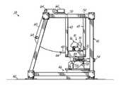
- FIG. 2is a perspective view of a pendulum tester having the test assembly of FIG. 1 mounted thereto;
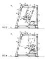
- FIG. 3is a side elevation view of the pendulum tester of FIG. 2 with the pendulum in a raised position;
- FIG. 4is a side elevation view of the pendulum tester of FIG. 3 showing the manikin assembly contacting the head restraint due to the deceleration of the pendulum.
- Test assembly 10for evaluating head restraint design concepts.
- Test assembly 10comprises a carriage 12 , a head restraint 14 coupled to carriage 12 and a manikin assembly 16 also coupled to carriage 12 adjacent head restraint 14 .
- Carriage 12comprises a generally rectangular plate having a top surface 18 .
- a head restraint mounting bracket 20is coupled to carriage 12 along top surface 18 by means known but not shown.
- a vehicle head restraint 14is then coupled to mounting bracket 20 .
- Mounting bracket 20may be adjustably positioned on carriage 12 .
- head restraint 14may be moveable in a direction generally parallel to carriage 12 so as to move head restraint 14 toward and away from a head portion 22 of manikin assembly 16 , as shown by arrow 17 .
- head restraint 14may be further moveable in a direction generally perpendicular to carriage 12 so as to adjust the height of the head restraint 14 relative to head portion 22 .
- Head restraint 14may also be pivotally coupled to carriage 12 , so as to be angularly adjustable as shown by arrow 21 , or coupled in other manners depending on the application needs.
- Manikin assembly 16is coupled to carriage 12 along top surface 18 by means known but not shown.
- Manikin assembly 16comprises head portion 22 coupled to a neck portion 24 at an upper end 23 of neck portion 24 .
- Manikin assembly 16is coupled to carriage 12 along a lower end 25 of neck portion 24 .
- Head and neck portions 22 , 24are configured to simulate the kinematic response of the human head and neck to motion, such as for example accelerating and/or decelerating motions.
- the term manikin assemblyis not to be limited to mechanical devices that simulate the human head and neck, but is broad enough to encompass cadaver head and neck portions.
- federally regulated anthropomorphic test device (ATD) componentssuch as the Hybrid III head and neck assemblies may be used in the invention.
- adult ATD componentsas well as child ATD components may be used. It should be noted, however, that the invention is not so limited and any head/neck ATD components may be used in the invention.
- manikin assembly 16may further comprise an upper neck load cell 26 adjacent the upper end 23 of neck assembly 24 and a lower neck load cell 28 adjacent the lower end 25 of neck assembly 24 .
- the upper and lower neck load cells 26 , 28are adapted to measure the rearward and forward shear forces, the tensile and compressive forces and the flexion and extension moments acting on the manikin assembly 16 at load cells 26 , 28 .
- manikin assembly 16may further include accelerometers 30 , 32 positioned adjacent the upper end 23 and lower end 25 of neck assembly 24 respectively. Accelerometer 30 is preferably placed at the center of gravity of head portion 22 .
- Accelerometers 30 , 32are adapted to measure the acceleration and/or deceleration of the manikin assembly 16 at accelerometers 30 , 32 .
- An accelerometer 34may further be positioned on carriage 12 to measure the acceleration and/or deceleration of test carriage 12 .
- test assembly 10can be mounted to a drive member that is capable of moving the test assembly.
- the manikin assembly 16responds through a corresponding movement of the head and neck portions 22 , 24 .
- the motion of the drive surfacecauses the head portion 22 to contact head restraint 14 .
- the dynamic datasuch as that measured by the load cells 26 , 28 and accelerometers 30 , 32 , 34 can be used in evaluating the performance and effectiveness of a particular head restraint design concept.
- Pendulum tester 38includes a frame structure 40 supported on top of a base 42 .
- a pendulum 44is pivotally connected to frame structure 40 by parallel support arms 43 , 45 .
- pendulum 44is capable of swinging movement between a raised position and a bottom position.
- Pendulum tester 38further includes a decelerator 46 located at the bottom position for engaging the pendulum 44 and decelerating the swinging movement of pendulum 44 .
- Pendulum 44comprises a generally planar rectangular surface 48 to which test assembly 10 , having the vehicle head restraint 14 and manikin assembly 16 mounted thereto, is coupled by means known but not shown.
- Support arms 43 , 45have one end pivotally connected to pendulum 44 and the other end pivotally connected to frame structure 40 at pivot joints 50 , 52 so that pendulum 44 is capable of swinging movement between a raised position and a bottom position.
- a decelerator 46is positioned at the bottom position of the pendulum 44 and supported on base 42 . Decelerator 46 comprises a pair of hydraulic dampers 54 for engaging bracket 56 , which extends downwardly from the bottom portion 58 of pendulum 44 .
- dampersmay be used in the invention, such as, adjustable/non-adjustable pneumatic dampers or energy absorbing materials or structures.
- bracket 56engages hydraulic dampers 54 to decelerate the swinging movement of pendulum 44 thereby causing the head portion 22 of manikin assembly 16 to contact head restraint 14 .
- the deceleration rate of pendulum 44may be controlled.
- the head restraint 14is mounted in mounting bracket 20 , which is coupled to carriage 12 .
- the manikin assembly 16is then mounted to carriage 12 and carriage 12 is then mounted to pendulum 44 .
- a lift assemblycomprising a lift cable 60 , winch 62 and pulleys 64 is actuated to raise or swing pendulum 44 to a raised position, as shown in FIG. 3 .
- the raised position of the pendulum 44may be selectively adjusted for controlling the velocity of the test assembly 10 .
- Lift cable 60is releasably attached to an end portion 66 of pendulum 44 and is released to allow swinging movement of the pendulum 44 toward the bottom position.
- the bracket 56engages against dampers 54 thereby decelerating the swinging movement of the pendulum 44 .
- this decelerationthen causes head and neck portions 22 , 24 to move abruptly in the rearward direction so that head portion 22 contacts head restraint 14 .
- Datasuch as the force data and the acceleration/deceleration data taken by load cells 26 , 28 and accelerometers 30 , 32 , 34 may be gathered. This data can then be used to evaluate the performance and effectiveness of a particular head restraint design.
- the pendulum tester 38represents but one embodiment of a drive member that may be used in the present invention.
- a drive memberthat may be used in the present invention.
- driven membersincluding, but not limited to, an acceleration sled, a deceleration sled or even something as simple as a vertical rail system having gravity-driven motion.
- decelerating motionis used in the described embodiment shown in FIGS. 2–4 , the present invention is not so limited and drive members capable of accelerating motions may also be used.
- the present inventionadvantageously provides an apparatus and method for evaluating vehicle head restraints under dynamic conditions without the need for performing a test on the overall seat assembly.
- the apparatus and method of the present inventionis not a substitute for the traditional sled test, as the sled test is the industry standard and is usually specifically mandated by federal regulations or OEM requirements. Instead, it is contemplated that the apparatus and method of the present invention may be used as a preliminary test to determine the likely response of a particular head restraint design concept during a traditional sled test of the overall seat assembly. With this in mind, and so that a comparison of the data between a test using the present invention and that of the traditional sled test correlate, some of the physical and dynamic parameters of a test using the present invention are determined by the values generally observed in the sled test.
- the distance between the manikin assembly 16 and the head restraint 14 on carriage 12is approximately the same as that used for the sled test.
- the pendulum height and damper resistanceare adjusted so that the T 1 (base of neck) velocity and acceleration/deceleration measured during a test using the present invention is approximately the same as the T 1 velocity and acceleration/deceleration observed in the sled test.
- the present inventionproduces results that correlate to the results for the head restraint during the sled test of the overall seat assembly. It will be appreciated that other types of test procedures and evaluations may be accomplished with an apparatus of the present invention.
- high speed videomay be used in conjunction with conventional photo targets on the carriage 12 , head restraint 14 , and head portion 22 .
- the photo target on the carriagewould be used for reference purposes to determine the movement of head restraint 14 and head portion 22 .
- one photo targetwould be placed at its center of gravity and another, for example, on the chin area.
- a number of head restraint design conceptsmay be evaluated without the need for testing the overall seat assembly. Typically, after tests using the present invention identify the best performers among the proposed design concepts will a sled test evaluating the overall seat assembly be performed. This results in substantial cost savings and time reduction.
Landscapes
- Physics & Mathematics (AREA)
- General Physics & Mathematics (AREA)
- Investigating Strength Of Materials By Application Of Mechanical Stress (AREA)
Abstract
Description
Claims (24)
Priority Applications (1)
| Application Number | Priority Date | Filing Date | Title |
|---|---|---|---|
| US10/708,689US6983638B2 (en) | 2004-03-18 | 2004-03-18 | Head restraint evaluator |
Applications Claiming Priority (1)
| Application Number | Priority Date | Filing Date | Title |
|---|---|---|---|
| US10/708,689US6983638B2 (en) | 2004-03-18 | 2004-03-18 | Head restraint evaluator |
Publications (2)
| Publication Number | Publication Date |
|---|---|
| US20050204800A1 US20050204800A1 (en) | 2005-09-22 |
| US6983638B2true US6983638B2 (en) | 2006-01-10 |
Family
ID=34984736
Family Applications (1)
| Application Number | Title | Priority Date | Filing Date |
|---|---|---|---|
| US10/708,689Expired - Fee RelatedUS6983638B2 (en) | 2004-03-18 | 2004-03-18 | Head restraint evaluator |
Country Status (1)
| Country | Link |
|---|---|
| US (1) | US6983638B2 (en) |
Cited By (6)
| Publication number | Priority date | Publication date | Assignee | Title |
|---|---|---|---|---|
| US20060028005A1 (en)* | 2004-08-03 | 2006-02-09 | Dell Eva Mark L | Proximity suppression system tester |
| US20060174689A1 (en)* | 2005-01-06 | 2006-08-10 | Ryan Miller | Method for preparing a motor vehicle for a crash test |
| US20080098831A1 (en)* | 2006-10-31 | 2008-05-01 | Lear Corporation | Seating surrogate |
| US20090019917A1 (en)* | 2007-07-18 | 2009-01-22 | Jui Jing Lim | Test assembly and method |
| KR20200130640A (en)* | 2019-05-10 | 2020-11-19 | 헝디엔 그룹 인누어보 일렉트릭 컴퍼니 리미티드 | Case assembly strength test device |
| DE102019129721B3 (en)* | 2019-11-05 | 2021-04-01 | ATD-LabTech GmbH | Brake device system, test pendulum assembly for performing neck certifications, and method for operating a test pendulum assembly |
Families Citing this family (9)
| Publication number | Priority date | Publication date | Assignee | Title |
|---|---|---|---|---|
| DE102007029783A1 (en)* | 2007-05-04 | 2008-11-06 | Takata-Petri Ag | Device and method for testing a motor vehicle seat |
| CN102818708B (en)* | 2011-06-08 | 2016-03-30 | 重庆车辆检测研究院有限公司 | Automobile cab and front and back end protective device checkout equipment |
| CN104677646B (en)* | 2015-03-10 | 2017-06-30 | 重庆长安汽车股份有限公司 | A kind of Evaluations for Ride Comfort of Vehicle Seats simulation test device |
| KR101702319B1 (en)* | 2015-05-15 | 2017-02-03 | 경희대학교 산학협력단 | Test dummy for collision test of human |
| DE102015006594B4 (en) | 2015-05-21 | 2020-09-17 | Gerhard Pfeifer | Test pendulum arrangement and method for operating a test pendulum arrangement |
| KR101745939B1 (en)* | 2015-06-16 | 2017-06-12 | 경희대학교 산학협력단 | Collision test apparatus for human injury evaluation |
| KR101755928B1 (en) | 2015-12-10 | 2017-07-07 | 현대자동차주식회사 | Test device for door outside handle of vehicle |
| CN106092486B (en)* | 2016-06-02 | 2018-08-24 | 新沂市时集建设发展有限公司 | A kind of combined type pendulum stand |
| CN106017899A (en)* | 2016-07-05 | 2016-10-12 | 国营芜湖机械厂 | Airplane seat constraint system function and airtight testing bench |
Citations (16)
| Publication number | Priority date | Publication date | Assignee | Title |
|---|---|---|---|---|
| US4201078A (en) | 1977-10-19 | 1980-05-06 | Toyota Jidosha Kogyo Kabushiki Kaisha | Horizontal-type head form impact tester |
| US5259765A (en)* | 1991-06-21 | 1993-11-09 | Simula Inc. | Biofidelic manikin neck |
| US5373749A (en) | 1993-04-29 | 1994-12-20 | Mts Systems Corporation | Vehicle head restraint tester |
| US5483845A (en)* | 1994-09-12 | 1996-01-16 | Morton International, Inc. | Apparatus and method for side impact testing |
| US5641917A (en) | 1995-12-01 | 1997-06-24 | Tachi-S Engineering, U.S.A., Inc. | Multi-axis seat durability test machine |
| US5922937A (en) | 1997-08-29 | 1999-07-13 | Lear Corporation | Individual component headform impact test drive |
| US6023984A (en) | 1998-01-28 | 2000-02-15 | Breed Automotive Technology, Inc. | Dynamic proximity test apparatus |
| US6035728A (en) | 1996-06-03 | 2000-03-14 | Breed Automotive Technology, Inc. | Test rig |
| US6131436A (en) | 1999-03-01 | 2000-10-17 | Lear Corporation | Method and system for wear testing a seat by simulating human seating activity and robotic human body simulator for use therein |
| US6381758B1 (en)* | 2001-02-22 | 2002-05-07 | Vanderbilt University | Head restraint system for racecar drivers |
| US6386054B1 (en)* | 1999-12-21 | 2002-05-14 | Visteon Global Tech., Inc. | Manikin assembly and method for the testing of seats which utilizes the assembly |
| US20020083783A1 (en)* | 2000-12-11 | 2002-07-04 | Chang-Nam Ahn | Anthropomorphic dummy head for use in vehicle crash test |
| US20020157450A1 (en)* | 2001-04-27 | 2002-10-31 | Hutchenreuther Alan J. | Proximity suppression system tester |
| US6561007B1 (en)* | 1997-12-11 | 2003-05-13 | Trw Occupant Restraint Systems Gmbh & Co. Kg | Device for carrying out side impact tests on motor vehicle passenger restraint systems |
| US6662093B2 (en)* | 2001-05-30 | 2003-12-09 | Eaton Corporation | Image processing system for detecting when an airbag should be deployed |
| US20040010398A1 (en)* | 2002-07-10 | 2004-01-15 | Mazda Motor Corporation | Program, method, apparatus, and system for supporting planning of vehicle |
- 2004
- 2004-03-18USUS10/708,689patent/US6983638B2/ennot_activeExpired - Fee Related
Patent Citations (17)
| Publication number | Priority date | Publication date | Assignee | Title |
|---|---|---|---|---|
| US4201078A (en) | 1977-10-19 | 1980-05-06 | Toyota Jidosha Kogyo Kabushiki Kaisha | Horizontal-type head form impact tester |
| US5259765A (en)* | 1991-06-21 | 1993-11-09 | Simula Inc. | Biofidelic manikin neck |
| US5373749A (en) | 1993-04-29 | 1994-12-20 | Mts Systems Corporation | Vehicle head restraint tester |
| US5483845A (en)* | 1994-09-12 | 1996-01-16 | Morton International, Inc. | Apparatus and method for side impact testing |
| US5641917A (en) | 1995-12-01 | 1997-06-24 | Tachi-S Engineering, U.S.A., Inc. | Multi-axis seat durability test machine |
| US6035728A (en) | 1996-06-03 | 2000-03-14 | Breed Automotive Technology, Inc. | Test rig |
| US5922937A (en) | 1997-08-29 | 1999-07-13 | Lear Corporation | Individual component headform impact test drive |
| US6561007B1 (en)* | 1997-12-11 | 2003-05-13 | Trw Occupant Restraint Systems Gmbh & Co. Kg | Device for carrying out side impact tests on motor vehicle passenger restraint systems |
| US6023984A (en) | 1998-01-28 | 2000-02-15 | Breed Automotive Technology, Inc. | Dynamic proximity test apparatus |
| US6131436A (en) | 1999-03-01 | 2000-10-17 | Lear Corporation | Method and system for wear testing a seat by simulating human seating activity and robotic human body simulator for use therein |
| US6386054B1 (en)* | 1999-12-21 | 2002-05-14 | Visteon Global Tech., Inc. | Manikin assembly and method for the testing of seats which utilizes the assembly |
| US20020083783A1 (en)* | 2000-12-11 | 2002-07-04 | Chang-Nam Ahn | Anthropomorphic dummy head for use in vehicle crash test |
| US6381758B1 (en)* | 2001-02-22 | 2002-05-07 | Vanderbilt University | Head restraint system for racecar drivers |
| US20020157450A1 (en)* | 2001-04-27 | 2002-10-31 | Hutchenreuther Alan J. | Proximity suppression system tester |
| US6672177B2 (en)* | 2001-04-27 | 2004-01-06 | Eaton Corporation | Proximity suppression system tester |
| US6662093B2 (en)* | 2001-05-30 | 2003-12-09 | Eaton Corporation | Image processing system for detecting when an airbag should be deployed |
| US20040010398A1 (en)* | 2002-07-10 | 2004-01-15 | Mazda Motor Corporation | Program, method, apparatus, and system for supporting planning of vehicle |
Non-Patent Citations (2)
| Title |
|---|
| Hans Cappon et al., A New Test Method for the Assessment of Neck Injuries in Rear-End Collisions, Article, undated. |
| Ola Bostrom et al., A Sled Tests Procedure Proposal to Evaluate the Risk of Neck Injury in Low Speed Rear Impacts Using a New Neck Injury Criterion(NIC), 16th ESV Conference, Jun. 1-4, 1998, Windsor, Canada. |
Cited By (9)
| Publication number | Priority date | Publication date | Assignee | Title |
|---|---|---|---|---|
| US20060028005A1 (en)* | 2004-08-03 | 2006-02-09 | Dell Eva Mark L | Proximity suppression system tester |
| US20060174689A1 (en)* | 2005-01-06 | 2006-08-10 | Ryan Miller | Method for preparing a motor vehicle for a crash test |
| US7448251B2 (en)* | 2005-01-06 | 2008-11-11 | Honda Motor Co., Ltd. | Method for preparing a motor vehicle for a crash test |
| US20080098831A1 (en)* | 2006-10-31 | 2008-05-01 | Lear Corporation | Seating surrogate |
| US20090019917A1 (en)* | 2007-07-18 | 2009-01-22 | Jui Jing Lim | Test assembly and method |
| US7555930B2 (en)* | 2007-07-18 | 2009-07-07 | Seagate Technology Llc | Test assembly and method |
| KR20200130640A (en)* | 2019-05-10 | 2020-11-19 | 헝디엔 그룹 인누어보 일렉트릭 컴퍼니 리미티드 | Case assembly strength test device |
| DE102019129721B3 (en)* | 2019-11-05 | 2021-04-01 | ATD-LabTech GmbH | Brake device system, test pendulum assembly for performing neck certifications, and method for operating a test pendulum assembly |
| US12339198B2 (en) | 2019-11-05 | 2025-06-24 | ATD-LabTech GmbH | Test pendulum arrangement for performing neck certifications and method for operating a test pendulum arrangement |
Also Published As
| Publication number | Publication date |
|---|---|
| US20050204800A1 (en) | 2005-09-22 |
Similar Documents
| Publication | Publication Date | Title |
|---|---|---|
| US6983638B2 (en) | Head restraint evaluator | |
| KR101547887B1 (en) | Sled test apparatus | |
| US6256601B1 (en) | Rollover test sled | |
| CN102680200B (en) | Airbag head hammer falling static testing device | |
| CA2572838C (en) | Device for simulating a side collision of a motor vehicle | |
| JP4911755B2 (en) | Collision test apparatus and collision test method for automobile body | |
| CN107817111B (en) | Safety air bag testing device | |
| CN107101835B (en) | Safety air bag testing device | |
| CN111141499A (en) | Safety belt testing device | |
| SE507769C2 (en) | Test device for crash testing of subsystems for passenger cars in simulated side collision | |
| CN112345271B (en) | Vehicle dynamic rollover test device and method | |
| US20140298887A1 (en) | Wheeled vehicle rollover performance testing system | |
| CN2769876Y (en) | Analog impact tester | |
| CN107101836B (en) | Flexible leg testing device and testing method | |
| US12339198B2 (en) | Test pendulum arrangement for performing neck certifications and method for operating a test pendulum arrangement | |
| US20110153298A1 (en) | Vehicle rollover simulation | |
| CN109870314B (en) | Seat vertical drop simulation vehicle rollover occurrence test device | |
| JP4795979B2 (en) | Vehicle collision simulation apparatus and method with inertia moment identification function | |
| KR100611411B1 (en) | Pendulum-type car crash performance test device | |
| KR20180077577A (en) | Crash test device of seat back for vehicle | |
| JPH05209806A (en) | Device for testing collision of vehicle | |
| JP2006138700A (en) | Simplified pitching device of automobile collision simulation test device | |
| CN103217975B (en) | Algorithm verification test device for air bag restraint system controller | |
| CN216050728U (en) | Detection device for measuring static expansion impact force of air bag | |
| KR20130025574A (en) | Collision simulation system |
Legal Events
| Date | Code | Title | Description |
|---|---|---|---|
| AS | Assignment | Owner name:LEAR CORPORATION, MICHIGAN Free format text:ASSIGNMENT OF ASSIGNORS INTEREST;ASSIGNORS:YETUKURI, NAGARJUN;HUMER, MLADEN;LOCKE, GERALD S.;AND OTHERS;REEL/FRAME:014429/0646 Effective date:20040315 | |
| AS | Assignment | Owner name:JPMORGAN CHASE BANK, N.A., AS GENERAL ADMINISTRATI Free format text:SECURITY AGREEMENT;ASSIGNOR:LEAR CORPORATION;REEL/FRAME:017858/0719 Effective date:20060425 | |
| FEPP | Fee payment procedure | Free format text:PAYOR NUMBER ASSIGNED (ORIGINAL EVENT CODE: ASPN); ENTITY STATUS OF PATENT OWNER: LARGE ENTITY | |
| REMI | Maintenance fee reminder mailed | ||
| LAPS | Lapse for failure to pay maintenance fees | ||
| STCH | Information on status: patent discontinuation | Free format text:PATENT EXPIRED DUE TO NONPAYMENT OF MAINTENANCE FEES UNDER 37 CFR 1.362 | |
| FP | Lapsed due to failure to pay maintenance fee | Effective date:20100110 | |
| AS | Assignment | Owner name:LEAR CORPORATION, MICHIGAN Free format text:RELEASE BY SECURED PARTY;ASSIGNOR:JPMORGAN CHASE BANK, N.A.;REEL/FRAME:032722/0553 Effective date:20100830 | |
| AS | Assignment | Owner name:LEAR CORPORATION, MICHIGAN Free format text:RELEASE BY SECURED PARTY;ASSIGNOR:JPMORGAN CHASE BANK, N.A., AS AGENT;REEL/FRAME:037731/0918 Effective date:20160104 |