US6983590B2 - Secondary air injection diagnostic system using pressure feedback - Google Patents
Secondary air injection diagnostic system using pressure feedbackDownload PDFInfo
- Publication number
- US6983590B2 US6983590B2US10/277,475US27747502AUS6983590B2US 6983590 B2US6983590 B2US 6983590B2US 27747502 AUS27747502 AUS 27747502AUS 6983590 B2US6983590 B2US 6983590B2
- Authority
- US
- United States
- Prior art keywords
- pressure
- pump
- pressure difference
- valve
- phase
- Prior art date
- Legal status (The legal status is an assumption and is not a legal conclusion. Google has not performed a legal analysis and makes no representation as to the accuracy of the status listed.)
- Expired - Fee Related
Links
Images


Classifications
- F—MECHANICAL ENGINEERING; LIGHTING; HEATING; WEAPONS; BLASTING
- F01—MACHINES OR ENGINES IN GENERAL; ENGINE PLANTS IN GENERAL; STEAM ENGINES
- F01N—GAS-FLOW SILENCERS OR EXHAUST APPARATUS FOR MACHINES OR ENGINES IN GENERAL; GAS-FLOW SILENCERS OR EXHAUST APPARATUS FOR INTERNAL-COMBUSTION ENGINES
- F01N11/00—Monitoring or diagnostic devices for exhaust-gas treatment apparatus
- F—MECHANICAL ENGINEERING; LIGHTING; HEATING; WEAPONS; BLASTING
- F01—MACHINES OR ENGINES IN GENERAL; ENGINE PLANTS IN GENERAL; STEAM ENGINES
- F01N—GAS-FLOW SILENCERS OR EXHAUST APPARATUS FOR MACHINES OR ENGINES IN GENERAL; GAS-FLOW SILENCERS OR EXHAUST APPARATUS FOR INTERNAL-COMBUSTION ENGINES
- F01N3/00—Exhaust or silencing apparatus having means for purifying, rendering innocuous, or otherwise treating exhaust
- F01N3/08—Exhaust or silencing apparatus having means for purifying, rendering innocuous, or otherwise treating exhaust for rendering innocuous
- F01N3/10—Exhaust or silencing apparatus having means for purifying, rendering innocuous, or otherwise treating exhaust for rendering innocuous by thermal or catalytic conversion of noxious components of exhaust
- F01N3/18—Exhaust or silencing apparatus having means for purifying, rendering innocuous, or otherwise treating exhaust for rendering innocuous by thermal or catalytic conversion of noxious components of exhaust characterised by methods of operation; Control
- F01N3/22—Control of additional air supply only, e.g. using by-passes or variable air pump drives
- F—MECHANICAL ENGINEERING; LIGHTING; HEATING; WEAPONS; BLASTING
- F01—MACHINES OR ENGINES IN GENERAL; ENGINE PLANTS IN GENERAL; STEAM ENGINES
- F01N—GAS-FLOW SILENCERS OR EXHAUST APPARATUS FOR MACHINES OR ENGINES IN GENERAL; GAS-FLOW SILENCERS OR EXHAUST APPARATUS FOR INTERNAL-COMBUSTION ENGINES
- F01N2550/00—Monitoring or diagnosing the deterioration of exhaust systems
- F01N2550/14—Systems for adding secondary air into exhaust
- Y—GENERAL TAGGING OF NEW TECHNOLOGICAL DEVELOPMENTS; GENERAL TAGGING OF CROSS-SECTIONAL TECHNOLOGIES SPANNING OVER SEVERAL SECTIONS OF THE IPC; TECHNICAL SUBJECTS COVERED BY FORMER USPC CROSS-REFERENCE ART COLLECTIONS [XRACs] AND DIGESTS
- Y02—TECHNOLOGIES OR APPLICATIONS FOR MITIGATION OR ADAPTATION AGAINST CLIMATE CHANGE
- Y02A—TECHNOLOGIES FOR ADAPTATION TO CLIMATE CHANGE
- Y02A50/00—TECHNOLOGIES FOR ADAPTATION TO CLIMATE CHANGE in human health protection, e.g. against extreme weather
- Y02A50/20—Air quality improvement or preservation, e.g. vehicle emission control or emission reduction by using catalytic converters
- Y—GENERAL TAGGING OF NEW TECHNOLOGICAL DEVELOPMENTS; GENERAL TAGGING OF CROSS-SECTIONAL TECHNOLOGIES SPANNING OVER SEVERAL SECTIONS OF THE IPC; TECHNICAL SUBJECTS COVERED BY FORMER USPC CROSS-REFERENCE ART COLLECTIONS [XRACs] AND DIGESTS
- Y02—TECHNOLOGIES OR APPLICATIONS FOR MITIGATION OR ADAPTATION AGAINST CLIMATE CHANGE
- Y02T—CLIMATE CHANGE MITIGATION TECHNOLOGIES RELATED TO TRANSPORTATION
- Y02T10/00—Road transport of goods or passengers
- Y02T10/10—Internal combustion engine [ICE] based vehicles
- Y02T10/40—Engine management systems
Definitions
- the present inventionrelates to secondary air injection systems of vehicles, and more particularly to secondary air injection diagnostic systems that employ pressure feedback.
- An engine control module of an internal combustion (IC) enginecontrols the mixture of fuel and air that is supplied to combustion chambers of the IC engine. After the spark plug ignites the air/fuel mixture, combustion gases exit the combustion chambers through exhaust valves. The combustion gases are directed by an exhaust manifold to a catalytic converter.
- ICinternal combustion
- combustion gases that enter the exhaust manifoldare not completely burned. The combustion gases will continue to burn in the exhaust manifold only if a sufficient amount of oxygen is available. Secondary air injection systems are typically used to inject additional air into the exhaust flow to allow combustion to continue, which reduces vehicle emissions. More particularly, prolonged combustion lowers levels of hydrocarbon (HC) and carbon monoxide (CO) emissions that are output to a catalytic converter. The additional air that is injected into the exhaust system also ensures that an adequate supply of oxygen is provided to the catalytic converter for further oxidation of HC and CO.
- HChydrocarbon
- COcarbon monoxide
- a diagnostic systemdiagnoses system failures of a secondary air injection system.
- the secondary air injection systemincludes a pump that provides air to an exhaust system via a conduit and a valve that controls the flow of air through the conduit.
- a pressure sensormeasures pressure in the conduit.
- a controllerpredicts pressure in the conduit during first, second and third operational phases of the secondary air injection system. The controller compares the measured pressure to the predicted pressure to evaluate the operation of the secondary air injection system.
- the pressure sensoris located between the pump and the valve.
- the secondary air injection systemis used to reduce vehicle emissions.
- the valveis shut while the pump remains on.
- the pumpis turned off while the valve remains closed.
- the controllercalculates a condition quality.
- the controllercalculates a first pressure difference between the measured pressure and the predicted pressure.
- the controllercalculates an average pressure difference by integrating a product of the first pressure difference and the condition quality, integrating the condition quality, and dividing the integrated product by the integrated condition quality.
- the controllercompares the average pressure difference to first and second thresholds and declares system failure if the average pressure difference is either less than the first threshold or greater than the second threshold.
- the controllercloses the valve while the pump is on.
- the controllercalculates the average pressure difference, compares the average pressure difference to a third threshold, and declares a valve failure if the average pressure difference is less than the third threshold.
- the controllerturns the pump off while the valve is closed.
- the controllercalculates the average pressure difference, compares the average pressure difference to a fourth threshold, and declares a pump failure if the average pressure difference is greater than the fourth threshold.
- FIG. 1is a functional block diagram of a secondary air injection diagnostic system according to the present invention
- FIGS. 2–4are flowcharts illustrating steps that are performed by the secondary air injection diagnostic system according to the present invention.
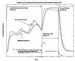
- FIG. 5is a graph illustrating modeled and measured pressure as a function of time.
- FIG. 6is a graph illustrating measured pressure and condition quality.
- the secondary air injection diagnostic systemmonitors the performance of the secondary air injection system by monitoring pressure.
- the diagnostic systemgenerates a predicted pressure. If the measured pressure deviates from the predicted pressure, the system is flagged as malfunctioning.
- the diagnostic systempredicts a normalized system pressure of 8 kPa.
- a system with a disabled pumphas a measured normalized pressure near 0 kPa. This deviation indicates a system malfunction.
- the measured normalized system pressureis about 15 kPa. A deviation above the predicted pressure value indicates a system malfunction.
- the secondary air injection diagnostic systemis also capable of detecting partially blocked or partially leaking secondary air systems as will be described more fully below.
- the secondary air injection system 12includes a pump 14 that is connected by one or more conduits 16 to control valves 18 - 1 and 18 - 2 and one way valves 20 - 1 and 20 - 2 .
- Additional conduit 22 - 1 and 22 - 2directs air into an exhaust manifold 24 - 1 and 24 - 2 of an engine 26 .
- valves 18 - 2 and 20 - 2 , conduit 22 - 2 and exhaust manifold 24 - 2are optional.
- the secondary air injection system 12includes a controller 30 that receives engine operating data and optionally provides engine inputs via control line 34 .
- Pressure sensors 36 - 1 and 36 - 2measure pressure in the conduit 16 .
- the pressure sensor 36 - 2is optional.
- the pressure sensors 36 - 1 and 36 - 2are located before the control valves 18 - 1 and 18 - 2 , respectively.
- the pressure sensors 36may be located in other positions between the pump and the exhaust manifold 24 . If there are two banks, one sensor is placed in the conduit between the split and each valve.
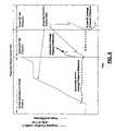
- the diagnostic system 10tests three different phases of operation of the secondary air injection system 12 .
- a first operational phaseoccurs while the secondary air injection system 12 is being used to reduce cold-start emissions.
- the pumpis turned on and the valve is open or modulated.
- the first phasetests normal secondary air system operation.
- a second phaseconfirms that the control valves 18 - 1 and 18 - 2 have closed.
- a third phaseconfirms that the pump shut down.
- the present inventionaccurately predicts pressure to allow a proper diagnosis of system operation.
- the pressure sensors 36Prior to engine rotation, the pressure sensors 36 provide a baseline pressure value.
- the baseline pressure valueis used to calculate the barometric pressure and to normalize the dynamic pressure value, which is the pressure after the engine begins operating. Normalization eliminates steady-state pressure signal errors as well as the barometric pressure.
- the diagnostic system 10also predicts the secondary air injection system pressure.
- the predictionis based on a simple model that approximates the secondary air injection system dynamics.
- the pump 14is turned on, the pump 14 component of the system pressure is calculated.
- the pump pressureis preferably based on the system voltage and barometric pressure.
- a filtersuch as a Kalman filter or any other suitable filter, is applied to the pump pressure to approximate system dynamics.
- the valve(s) 18are commanded on, the valve component of the system pressure is calculated.
- the valve de-pressureis based on the primary mass-airflow of the engine 26 .
- the valve de-pressureis also filtered, using a Kalman filter or any other suitable filter, to approximate system dynamics.
- the pump pressure and valve de-pressureare added together and filtered, using a Kalman filter or any other suitable filter.
- the predicted pressure valueis used by each phase of the diagnostic.
- the diagnostic system 10tests the normal operation of the system.
- an average pressure differenceis used to evaluate system performance.
- the measured normalized pressureis compared to the predicted pressure.
- Operating conditionsare evaluated for quality (condition quality) and a multiplier between 0 and 1 is assigned (0 associated with poor conditions and 1 with perfect conditions).
- the condition qualityis multiplied by the difference between the measured pressure and predicted pressure.
- the product and the instantaneous condition qualityare integrated.
- the average pressure difference(between the measured and predicted pressure) is the integrated instantaneous-pressure-difference divided by the integrated instantaneous-condition-quality.
- the average pressure differenceis compared to minimum and maximum thresholds to determine whether the secondary air injection system 12 is operating in an acceptable manner. If the system 12 has two valves 18 and two pressure sensors 36 , the variation between the two pressure measurements is averaged. If sufficient information is available when the secondary air is done being used to control emissions, the average sensor variation is compared to the thresholds to determine whether the system 12 is operating in an acceptable manner.
- the diagnostic system 10When unacceptable system operation is detected (for either pressure-model differences or sensor-sensor variations), the diagnostic system 10 preferably stops testing immediately and does not perform testing in the second or third phases. A system failure is reported and the diagnostic system 10 does not run until the next vehicle start. However, the secondary air injection passes the first phase test if a failure is not detected and enough favorable operating conditions have been encountered when the control system is finished using secondary injection air. After operation of the pump 14 is terminated for emissions control purposes, the diagnostic system 10 tests the second phase.
- the diagnostic system 10determines whether the control valves 18 shut properly.
- the control valves 18preferably shut when the controller 30 is finished using secondary injection air to control vehicle emissions.
- the pump 14remains on and the pressure should rise quickly.
- the diagnostic system 10calculates a new average pressure difference in a manner that is similar to the first phase. If the pressure difference is sufficiently large (that is, the measured pressure is larger than the predicted pressure threshold) and the diagnostic system 10 has accumulated enough reliable data (based on operating conditions as in the first phase), the diagnostic system 10 declares the valve(s) 18 to be shut.
- the controller 30turns the pump 14 off. Further, the diagnostic system 10 stops testing and waits for the third phase.
- the diagnostic system 10If the pressure difference is small (or negative) and enough reliable data has been accumulated when the controller 30 disengages the pump 14 , the diagnostic system 10 assumes there is a failure in the secondary air injection system. The diagnostic system 10 reports a valve failure and does not test the third phase.
- the diagnostic system 10confirms that the pump 14 has shut-off properly.
- the diagnostic system 10calculates a new average pressure difference and accumulates data as described above in the first and second phases. If sufficient data has been gathered and the average pressure difference is sufficiently small (or negative), the pump 14 is assumed to be off. If all of the phases were passed, the diagnostic system 10 reports that the secondary air injection system 12 is operating correctly. If sufficient data has been gathered, a time limit is reached, and the pressure difference is still large, the diagnostic system 10 declares the pump 14 is operating incorrectly and reports the failure.
- Each phase of testingcan make a local pass/fail decision if sufficient data is available. As soon as any phase encounters a failure, the diagnostic system 10 reports the appropriate failure and completes operation until the next vehicle start. The diagnostic system 10 preferably reports a pass for each test after each test passes locally.
- step 102control begins.
- step 104the controller 30 determines whether secondary air was performed this trip. If not, the controller 30 normalizes the pressure, calculates average pressure difference from a model, calculates average difference between sensors, and quantifies condition quality in step 106 . Control continues from step 106 to step 104 . If step 104 is true, the controller 30 determines whether there is enough data in step 108 . If not, the controller 30 performs a valve shut test in step 112 . If step 108 is true, the controller 30 determines whether the data is outside of an acceptable range in step 114 .
- step 114the controller 30 reports a test failure in step 116 and control ends in step 118 . If step 114 is false, the controller 30 reports a test pass in step 124 . Control continues from step 124 to step 112 where control performs the valve shut test.
- step 154the controller 30 determines whether the pump has been commanded on. If true, the controller 30 normalizes the pressure, calculates average pressure difference, and quantifies condition quality in step 158 . Control continues from step 158 to step 160 where the controller 30 determines whether there is enough data. If not, control loops back to step 154 . If step 160 is true, control determines whether the data is below an acceptable maximum in step 162 . If not, control loops back to step 154 . If step 162 is true, control continues with step 164 and reports a valve shut test pass. In step 166 , the pump is turned off. In step 168 , a pump off test is performed.
- step 154determines whether there is enough data. If step 172 is false, the controller 30 determines whether a time limit has been exceeded in step 174 . If step 174 is false, control continues with step 168 . If step 174 is true, control ends in step 178 .
- step 172the controller 30 determines whether the data is below an acceptable maximum in step 180 . If step 180 is true, the controller 30 continues with step 164 . If step 180 is false, the controller 30 reports a valve shut test fail in step 184 . Control ends in step 178 .
- step 204the controller 30 determines whether time limit A has been exceeded. If step 204 is true, control ends in step 206 . If step 204 is false, control continues with step 208 where the controller 30 determines whether the pump has been commanded off. If false, control loops back to step 204 . If true, control continues with step 210 and normalizes the pressure, calculates average pressure difference, and quantifies condition quality.
- step 214the controller 30 determines whether time limit B is up. If not, control continues with step 216 where the controller 30 determines whether there is enough data. If not, control loops back to step 204 . If there is enough data, control continues with step 218 where the controller 30 determines whether the data is above an acceptable minimum. If not, control loops back to step 204 . If step 218 is true, the controller 30 reports pump off test pass in step 220 and control ends in step 206 .
- step 214the controller 30 determines whether there is enough data in step 224 . If not, control ends in step 206 . If step 224 is true, the controller 30 determines whether the data is above an acceptable minimum in step 226 . If not, the controller 30 reports pump off test fail in step 230 and control ends in step 206 . If step 226 is true, control continues with step 220 .
- FIGS. 5 and 6show predicted pressure, measured pressure and the condition quality.
- the pressureis modeled according to the following equations.
- Dis a fixed time delay of span “K y ” during which a change in Boolean “u” subject to D(u,K y ) is postponed.
- [Modeled Pressure]F ([Pump Term]+[Valve Term], K 10 )
- the condition quality integralis the metric that indicates whether enough information has accumulated.
Landscapes
- Engineering & Computer Science (AREA)
- Chemical & Material Sciences (AREA)
- Chemical Kinetics & Catalysis (AREA)
- Combustion & Propulsion (AREA)
- Mechanical Engineering (AREA)
- General Engineering & Computer Science (AREA)
- Health & Medical Sciences (AREA)
- Toxicology (AREA)
- Exhaust Gas After Treatment (AREA)
Abstract
Description
[Pump Term]=F(D(Pump State {off=0, on=1}], K1)×(K2+K3×[System Voltage]+K4×[Barometric Pressure]),K5).
[Valve Term]=F(D([Valve State {closed=0, open=1}], K6)×(K7+K8×[Engine Airflow]),K9)
[Modeled Pressure]=F([Pump Term]+[Valve Term],K10)
Claims (26)
Priority Applications (2)
| Application Number | Priority Date | Filing Date | Title |
|---|---|---|---|
| US10/277,475US6983590B2 (en) | 2002-10-22 | 2002-10-22 | Secondary air injection diagnostic system using pressure feedback |
| DE10344910ADE10344910B4 (en) | 2002-10-22 | 2003-09-26 | Diagnostic process and diagnostic system for secondary air injection using pressure feedback |
Applications Claiming Priority (1)
| Application Number | Priority Date | Filing Date | Title |
|---|---|---|---|
| US10/277,475US6983590B2 (en) | 2002-10-22 | 2002-10-22 | Secondary air injection diagnostic system using pressure feedback |
Publications (2)
| Publication Number | Publication Date |
|---|---|
| US20040074453A1 US20040074453A1 (en) | 2004-04-22 |
| US6983590B2true US6983590B2 (en) | 2006-01-10 |
Family
ID=32093301
Family Applications (1)
| Application Number | Title | Priority Date | Filing Date |
|---|---|---|---|
| US10/277,475Expired - Fee RelatedUS6983590B2 (en) | 2002-10-22 | 2002-10-22 | Secondary air injection diagnostic system using pressure feedback |
Country Status (2)
| Country | Link |
|---|---|
| US (1) | US6983590B2 (en) |
| DE (1) | DE10344910B4 (en) |
Cited By (25)
| Publication number | Priority date | Publication date | Assignee | Title |
|---|---|---|---|---|
| US20050138919A1 (en)* | 2003-12-26 | 2005-06-30 | Denso Corporation | Secondary air supply system and fuel injection amount control apparatus using the same |
| US20060048504A1 (en)* | 2004-09-03 | 2006-03-09 | Toyota Jidosha Kabushiki Kaisha | Device for supplying secondary air |
| US20060059898A1 (en)* | 2004-09-17 | 2006-03-23 | Denso Corporation | Diagnostic device for secondary air supply system |
| US20060090455A1 (en)* | 2004-10-29 | 2006-05-04 | Denso Corporation | Abnormality diagnosis apparatus for secondary air supply system of engine |
| US20070213662A1 (en)* | 2004-11-24 | 2007-09-13 | Medrad, Inc. | System And Apparatus For Modeling Pressures Generated During An Injection Procedure |
| US20080120967A1 (en)* | 2006-11-27 | 2008-05-29 | Toyota Engineering & Manufacturing North America, Inc. | Method of calculating airflow introduction into an automotive exhaust air injection system |
| US9008759B2 (en) | 2007-07-17 | 2015-04-14 | Bayer Medical Care Inc. | Devices and systems for determination of parameters for a procedure, for estimation of cardiopulmonary function and for fluid delivery |
| US9115628B2 (en) | 2013-09-04 | 2015-08-25 | Denso International America, Inc. | Feed tube restriction for on board diagnostic compliance in secondary air injection applications on V-engines |
| US9421330B2 (en) | 2008-11-03 | 2016-08-23 | Bayer Healthcare Llc | Mitigation of contrast-induced nephropathy |
| US9949704B2 (en) | 2012-05-14 | 2018-04-24 | Bayer Healthcare Llc | Systems and methods for determination of pharmaceutical fluid injection protocols based on x-ray tube voltage |
| US9959389B2 (en) | 2010-06-24 | 2018-05-01 | Bayer Healthcare Llc | Modeling of pharmaceutical propagation and parameter generation for injection protocols |
| US10190462B2 (en) | 2014-06-06 | 2019-01-29 | Continental Automotive Gmbh | Pump for a secondary air system of an internal combustion engine |
| DE102018100540A1 (en)* | 2018-01-11 | 2019-07-11 | Pierburg Gmbh | Method for diagnosing an air supply system for introducing air into an exhaust system of an internal combustion engine |
| US10463782B2 (en) | 2006-12-29 | 2019-11-05 | Bayer Healthcare Llc | Patient-based parameter generation systems for medical injection procedures |
| US10898638B2 (en) | 2016-03-03 | 2021-01-26 | Bayer Healthcare Llc | System and method for improved fluid delivery in multi-fluid injector systems |
| US11141535B2 (en) | 2017-08-31 | 2021-10-12 | Bayer Healthcare Llc | Fluid path impedance assessment for improving fluid delivery performance |
| US11278853B2 (en) | 2013-03-13 | 2022-03-22 | Bayer Healthcare Llc | Method for controlling fluid accuracy and backflow compensation |
| US11478581B2 (en) | 2017-08-31 | 2022-10-25 | Bayer Healthcare Llc | Fluid injector system volume compensation system and method |
| US11598664B2 (en) | 2017-08-31 | 2023-03-07 | Bayer Healthcare Llc | Injector pressure calibration system and method |
| US11779702B2 (en) | 2017-08-31 | 2023-10-10 | Bayer Healthcare Llc | Method for dynamic pressure control in a fluid injector system |
| US11786652B2 (en) | 2017-08-31 | 2023-10-17 | Bayer Healthcare Llc | System and method for drive member position and fluid injector system mechanical calibration |
| US12208239B2 (en) | 2018-08-28 | 2025-01-28 | Bayer Healthcare Llc | Fluid injector system, method of preventing fluid backflow, and computer program product |
| US12251544B2 (en) | 2018-04-19 | 2025-03-18 | Bayer Healthcare Llc | System and method for air detection in fluid injector |
| US12263326B2 (en) | 2016-11-14 | 2025-04-01 | Bayer Healthcare Llc | Methods and systems for verifying the contents of a syringe used for medical fluid delivery |
| US12427249B2 (en) | 2018-08-28 | 2025-09-30 | Bayer Healthcare Llc | Fluid injector system with improved ratio performance |
Families Citing this family (27)
| Publication number | Priority date | Publication date | Assignee | Title |
|---|---|---|---|---|
| AUPQ867900A0 (en) | 2000-07-10 | 2000-08-03 | Medrad, Inc. | Medical injector system |
| DE10248627B4 (en)* | 2002-10-18 | 2014-05-22 | Robert Bosch Gmbh | Method for operating an internal combustion engine, internal combustion engine and control device therefor |
| JP4186679B2 (en)* | 2003-04-03 | 2008-11-26 | トヨタ自動車株式会社 | Failure diagnosis device for secondary air supply device. |
| US7666169B2 (en) | 2003-11-25 | 2010-02-23 | Medrad, Inc. | Syringe and syringe plungers for use with medical injectors |
| USD1031029S1 (en) | 2003-11-25 | 2024-06-11 | Bayer Healthcare Llc | Syringe plunger |
| JP4337689B2 (en)* | 2004-08-30 | 2009-09-30 | トヨタ自動車株式会社 | Control device for internal combustion engine |
| DE102005009464B4 (en)* | 2005-03-02 | 2016-07-21 | Robert Bosch Gmbh | Method for diagnosing a system for metering reagent and compressed air into the exhaust area of an internal combustion engine and device for carrying out the method |
| US20170046458A1 (en) | 2006-02-14 | 2017-02-16 | Power Analytics Corporation | Systems and methods for real-time dc microgrid power analytics for mission-critical power systems |
| WO2007095585A2 (en)* | 2006-02-14 | 2007-08-23 | Edsa Micro Corporation | Systems and methods for real-time system monitoring and predictive analysis |
| US8926569B2 (en) | 2006-03-15 | 2015-01-06 | Bayer Medical Care Inc. | Plunger covers and plungers for use in syringes and methods of fabricating plunger covers and plungers for use in syringes |
| USD1002840S1 (en) | 2007-03-14 | 2023-10-24 | Bayer Healthcare Llc | Syringe plunger |
| USD847985S1 (en) | 2007-03-14 | 2019-05-07 | Bayer Healthcare Llc | Syringe plunger cover |
| USD942005S1 (en) | 2007-03-14 | 2022-01-25 | Bayer Healthcare Llc | Orange syringe plunger cover |
| EP2147202B1 (en)* | 2007-04-19 | 2012-02-01 | Volvo Lastvagnar AB | Method and arrangement for monitoring of injector |
| US20110082597A1 (en) | 2009-10-01 | 2011-04-07 | Edsa Micro Corporation | Microgrid model based automated real time simulation for market based electric power system optimization |
| US9174003B2 (en) | 2012-09-28 | 2015-11-03 | Bayer Medical Care Inc. | Quick release plunger |
| US9234449B2 (en)* | 2012-10-19 | 2016-01-12 | GM Global Technology Operations LLC | Leak and blockage diagnostic systems and methods |
| AU2015231396B2 (en) | 2014-03-19 | 2018-12-06 | Bayer Healthcare Llc | System for syringe engagement to an injector |
| US9480797B1 (en) | 2015-10-28 | 2016-11-01 | Bayer Healthcare Llc | System and method for syringe plunger engagement with an injector |
| HUE063479T2 (en) | 2017-01-06 | 2024-01-28 | Bayer Healthcare Llc | Syringe plunger with dynamic seal |
| HUE061426T2 (en) | 2018-02-27 | 2023-06-28 | Bayer Healthcare Llc | Syringe piston switch mechanism |
| DE102019218709B4 (en) | 2019-12-02 | 2021-12-09 | Vitesco Technologies GmbH | Method and device for coking diagnosis of a secondary air system of an internal combustion engine |
| BR112022023788A2 (en) | 2020-06-18 | 2022-12-27 | Bayer Healthcare Llc | SYSTEM AND METHOD OF COUPLING A SYRINGE PLUNGER WITH AN INJECTOR |
| DE102022213545A1 (en) | 2022-12-13 | 2024-06-13 | Robert Bosch Gesellschaft mit beschränkter Haftung | Air supply to an internal combustion engine and method and device for diagnosing an air supply to an internal combustion engine |
| DE102022213542A1 (en)* | 2022-12-13 | 2024-06-13 | Robert Bosch Gesellschaft mit beschränkter Haftung | Air supply to an internal combustion engine and method and device for diagnosing an air supply to an internal combustion engine |
| DE102022214200A1 (en) | 2022-12-21 | 2024-06-27 | Robert Bosch Gesellschaft mit beschränkter Haftung | Method for operating a system for supplying air to a burner |
| DE102023204320B3 (en) | 2023-05-10 | 2024-04-18 | Vitesco Technologies GmbH | Method for modelling the pressure in a secondary air system of a motor vehicle having a secondary air pump |
Citations (7)
| Publication number | Priority date | Publication date | Assignee | Title |
|---|---|---|---|---|
| US3894984A (en)* | 1973-03-08 | 1975-07-15 | Basf Ag | Manufacture of curable polyester molding compositions |
| US5706653A (en)* | 1995-03-07 | 1998-01-13 | Nissan Motor Co., Ltd. | Secondary air supplying apparatus for internal combustion engine |
| US5743085A (en)* | 1993-04-09 | 1998-04-28 | Hitachi, Ltd. | Diagnostic equipment for an exhaust gas cleaning apparatus |
| US5782086A (en)* | 1995-07-04 | 1998-07-21 | Honda Giken Kogyo Kabushiki Kaiha | Failure detection system of exhaust secondary air supply system of internal combustion engine |
| US5814283A (en)* | 1995-11-09 | 1998-09-29 | Toyota Jidosha Kabushiki Kaisha | Exhaust purifier of internal combustion engine |
| US5852929A (en)* | 1995-07-04 | 1998-12-29 | Honda Giken Kogyo Kabushiki Kaisha | Failure detection system of exhaust secondary air supply system of internal combustion engine |
| US20030061805A1 (en)* | 2001-09-14 | 2003-04-03 | Toyota Jidosha Kabushiki Kaisha | Secondary air supply apparatus and method for detecting abnormality thereof |
Family Cites Families (2)
| Publication number | Priority date | Publication date | Assignee | Title |
|---|---|---|---|---|
| DE4120891A1 (en)* | 1991-06-25 | 1993-01-07 | Bayerische Motoren Werke Ag | Combustion engine pumping fresh air into exhaust system - is checked for correct exhaust treatment function by direct or indirect measurement of pump power consumption |
| DE19713180C1 (en)* | 1997-03-27 | 1998-09-24 | Siemens Ag | Method for monitoring the secondary air mass flow of an exhaust gas cleaning system |
- 2002
- 2002-10-22USUS10/277,475patent/US6983590B2/ennot_activeExpired - Fee Related
- 2003
- 2003-09-26DEDE10344910Apatent/DE10344910B4/ennot_activeExpired - Fee Related
Patent Citations (7)
| Publication number | Priority date | Publication date | Assignee | Title |
|---|---|---|---|---|
| US3894984A (en)* | 1973-03-08 | 1975-07-15 | Basf Ag | Manufacture of curable polyester molding compositions |
| US5743085A (en)* | 1993-04-09 | 1998-04-28 | Hitachi, Ltd. | Diagnostic equipment for an exhaust gas cleaning apparatus |
| US5706653A (en)* | 1995-03-07 | 1998-01-13 | Nissan Motor Co., Ltd. | Secondary air supplying apparatus for internal combustion engine |
| US5782086A (en)* | 1995-07-04 | 1998-07-21 | Honda Giken Kogyo Kabushiki Kaiha | Failure detection system of exhaust secondary air supply system of internal combustion engine |
| US5852929A (en)* | 1995-07-04 | 1998-12-29 | Honda Giken Kogyo Kabushiki Kaisha | Failure detection system of exhaust secondary air supply system of internal combustion engine |
| US5814283A (en)* | 1995-11-09 | 1998-09-29 | Toyota Jidosha Kabushiki Kaisha | Exhaust purifier of internal combustion engine |
| US20030061805A1 (en)* | 2001-09-14 | 2003-04-03 | Toyota Jidosha Kabushiki Kaisha | Secondary air supply apparatus and method for detecting abnormality thereof |
Cited By (38)
| Publication number | Priority date | Publication date | Assignee | Title |
|---|---|---|---|---|
| US7284369B2 (en)* | 2003-12-26 | 2007-10-23 | Denso Corporation | Secondary air supply system and fuel injection amount control apparatus using the same |
| US20050138919A1 (en)* | 2003-12-26 | 2005-06-30 | Denso Corporation | Secondary air supply system and fuel injection amount control apparatus using the same |
| US20060048504A1 (en)* | 2004-09-03 | 2006-03-09 | Toyota Jidosha Kabushiki Kaisha | Device for supplying secondary air |
| US7222483B2 (en)* | 2004-09-03 | 2007-05-29 | Toyota Jidosha Kabushiki Kaisha | Device for supplying secondary air |
| US20060059898A1 (en)* | 2004-09-17 | 2006-03-23 | Denso Corporation | Diagnostic device for secondary air supply system |
| US7260928B2 (en)* | 2004-09-17 | 2007-08-28 | Denso Corporation | Diagnostic device for secondary air supply system |
| US20060090455A1 (en)* | 2004-10-29 | 2006-05-04 | Denso Corporation | Abnormality diagnosis apparatus for secondary air supply system of engine |
| US9238099B2 (en)* | 2004-11-24 | 2016-01-19 | Bayer Healthcare Llc | System and apparatus for modeling pressures generated during an injection procedure |
| US20070213662A1 (en)* | 2004-11-24 | 2007-09-13 | Medrad, Inc. | System And Apparatus For Modeling Pressures Generated During An Injection Procedure |
| US20070282263A1 (en)* | 2004-11-24 | 2007-12-06 | Medrad, Inc. | Devices, systems and methods for determining parameters of one or more phases of an injection procedure |
| US10166326B2 (en) | 2004-11-24 | 2019-01-01 | Bayer Healthcare Llc | Devices, systems and methods for determining parameters of one or more phases of an injection procedure |
| US7925330B2 (en) | 2004-11-24 | 2011-04-12 | Medrad, Inc. | Devices, systems and methods for determining parameters of one or more phases of an injection procedure |
| US20080120967A1 (en)* | 2006-11-27 | 2008-05-29 | Toyota Engineering & Manufacturing North America, Inc. | Method of calculating airflow introduction into an automotive exhaust air injection system |
| US7487632B2 (en) | 2006-11-27 | 2009-02-10 | Toyota Motor Engineering & Manufacturing North America, Inc. | Method of calculating airflow introduction into an automotive exhaust air injection system |
| US10463782B2 (en) | 2006-12-29 | 2019-11-05 | Bayer Healthcare Llc | Patient-based parameter generation systems for medical injection procedures |
| US9008759B2 (en) | 2007-07-17 | 2015-04-14 | Bayer Medical Care Inc. | Devices and systems for determination of parameters for a procedure, for estimation of cardiopulmonary function and for fluid delivery |
| US9421330B2 (en) | 2008-11-03 | 2016-08-23 | Bayer Healthcare Llc | Mitigation of contrast-induced nephropathy |
| US9959389B2 (en) | 2010-06-24 | 2018-05-01 | Bayer Healthcare Llc | Modeling of pharmaceutical propagation and parameter generation for injection protocols |
| US11191501B2 (en) | 2012-05-14 | 2021-12-07 | Bayer Healthcare Llc | Systems and methods for determination of pharmaceutical fluid injection protocols based on x-ray tube voltage |
| US9949704B2 (en) | 2012-05-14 | 2018-04-24 | Bayer Healthcare Llc | Systems and methods for determination of pharmaceutical fluid injection protocols based on x-ray tube voltage |
| US11278853B2 (en) | 2013-03-13 | 2022-03-22 | Bayer Healthcare Llc | Method for controlling fluid accuracy and backflow compensation |
| US9115628B2 (en) | 2013-09-04 | 2015-08-25 | Denso International America, Inc. | Feed tube restriction for on board diagnostic compliance in secondary air injection applications on V-engines |
| US10190462B2 (en) | 2014-06-06 | 2019-01-29 | Continental Automotive Gmbh | Pump for a secondary air system of an internal combustion engine |
| US11672902B2 (en) | 2016-03-03 | 2023-06-13 | Bayer Healthcare Llc | System and method for improved fluid delivery in multi-fluid injector systems |
| US10898638B2 (en) | 2016-03-03 | 2021-01-26 | Bayer Healthcare Llc | System and method for improved fluid delivery in multi-fluid injector systems |
| US12263326B2 (en) | 2016-11-14 | 2025-04-01 | Bayer Healthcare Llc | Methods and systems for verifying the contents of a syringe used for medical fluid delivery |
| US11478581B2 (en) | 2017-08-31 | 2022-10-25 | Bayer Healthcare Llc | Fluid injector system volume compensation system and method |
| US11598664B2 (en) | 2017-08-31 | 2023-03-07 | Bayer Healthcare Llc | Injector pressure calibration system and method |
| US11141535B2 (en) | 2017-08-31 | 2021-10-12 | Bayer Healthcare Llc | Fluid path impedance assessment for improving fluid delivery performance |
| US11779702B2 (en) | 2017-08-31 | 2023-10-10 | Bayer Healthcare Llc | Method for dynamic pressure control in a fluid injector system |
| US11786652B2 (en) | 2017-08-31 | 2023-10-17 | Bayer Healthcare Llc | System and method for drive member position and fluid injector system mechanical calibration |
| US11826553B2 (en) | 2017-08-31 | 2023-11-28 | Bayer Healthcare Llc | Fluid path impedance assessment for improving fluid delivery performance |
| US12214155B2 (en) | 2017-08-31 | 2025-02-04 | Bayer Healthcare Llc | Fluid injector system volume compensation system and method |
| DE102018100540B4 (en) | 2018-01-11 | 2023-01-26 | Pierburg Gmbh | Method for diagnosing an air supply system for introducing air into an exhaust system of an internal combustion engine |
| DE102018100540A1 (en)* | 2018-01-11 | 2019-07-11 | Pierburg Gmbh | Method for diagnosing an air supply system for introducing air into an exhaust system of an internal combustion engine |
| US12251544B2 (en) | 2018-04-19 | 2025-03-18 | Bayer Healthcare Llc | System and method for air detection in fluid injector |
| US12208239B2 (en) | 2018-08-28 | 2025-01-28 | Bayer Healthcare Llc | Fluid injector system, method of preventing fluid backflow, and computer program product |
| US12427249B2 (en) | 2018-08-28 | 2025-09-30 | Bayer Healthcare Llc | Fluid injector system with improved ratio performance |
Also Published As
| Publication number | Publication date |
|---|---|
| DE10344910A1 (en) | 2004-05-13 |
| DE10344910B4 (en) | 2006-06-08 |
| US20040074453A1 (en) | 2004-04-22 |
Similar Documents
| Publication | Publication Date | Title |
|---|---|---|
| US6983590B2 (en) | Secondary air injection diagnostic system using pressure feedback | |
| EP0663516B1 (en) | Malfunction monitoring apparatus and method for secondary air supply system of internal combustion engine | |
| US7222615B2 (en) | Method and device for operating an internal combustion engine having exhaust-gas recirculation | |
| US7536851B2 (en) | Catalyst condition monitor based on differential area under the oxygen sensors curve algorithm | |
| US5331560A (en) | Apparatus and method for self diagnosing engine component controlling systems according to predetermined levels of priority | |
| US7367188B2 (en) | System and method for diagnostic of low pressure exhaust gas recirculation system and adapting of measurement devices | |
| US7881852B2 (en) | Method and device for detecting a leak in an exhaust-gas section of a combustion engine | |
| US9874171B2 (en) | Method and device for controlling an internal combustion engine | |
| US8666639B2 (en) | Fuel supply control apparatus for engine, and fuel supply control method therefor | |
| JP2926917B2 (en) | Vehicle abnormality diagnosis device | |
| JPH10141150A (en) | Failure diagnosis device for engine exhaust gas recirculation control device | |
| KR101316863B1 (en) | System and method for monitoring exhaust gas recirculation | |
| US20030061805A1 (en) | Secondary air supply apparatus and method for detecting abnormality thereof | |
| US5103655A (en) | Diagnostic arrangement for automotive engine EGR system | |
| US20040200208A1 (en) | Method and apparatus for monitoring catalyst efficiency and outlet oxygen sensor performance | |
| JP2009257280A (en) | Diagnostic device of exhaust gas recirculation system | |
| US6393833B2 (en) | Abnormality test method and apparatus for secondary air supply system of a vehicle | |
| US6581371B1 (en) | Engine catalyst monitor | |
| KR101725641B1 (en) | stuck diagnosis method for canister purge valve and vehicle system therefor | |
| US11746687B2 (en) | EHC line leakage diagnosis method and vehicle exhaust system thereof | |
| US6871136B1 (en) | Method for on-board diagnosis of cold start emissions reduction control strategy | |
| US20240191645A1 (en) | Air supply to an internal combustion engine and method and device for diagnosing an air supply to an internal combustion engine | |
| JP3663921B2 (en) | Oxygen sensor diagnostic device | |
| GB2440317A (en) | Functionality testing of secondary air injection systems | |
| JPH07310585A (en) | Cylinder pressure sensor diagnostic device |
Legal Events
| Date | Code | Title | Description |
|---|---|---|---|
| AS | Assignment | Owner name:GENERAL MOTORS CORPORATION, MICHIGAN Free format text:ASSIGNMENT OF ASSIGNORS INTEREST;ASSIGNORS:ROELLE, MATTHEW J.;HALL, MARTIN L.;HOOKER, DANIEL H.;AND OTHERS;REEL/FRAME:013679/0127;SIGNING DATES FROM 20020919 TO 20021014 | |
| AS | Assignment | Owner name:GM GLOBAL TECHNOLOGY OPERATIONS, INC., MICHIGAN Free format text:ASSIGNMENT OF ASSIGNORS INTEREST;ASSIGNOR:GENERAL MOTORS CORPORATION;REEL/FRAME:022117/0001 Effective date:20050119 Owner name:GM GLOBAL TECHNOLOGY OPERATIONS, INC.,MICHIGAN Free format text:ASSIGNMENT OF ASSIGNORS INTEREST;ASSIGNOR:GENERAL MOTORS CORPORATION;REEL/FRAME:022117/0001 Effective date:20050119 | |
| AS | Assignment | Owner name:UNITED STATES DEPARTMENT OF THE TREASURY, DISTRICT Free format text:SECURITY AGREEMENT;ASSIGNOR:GM GLOBAL TECHNOLOGY OPERATIONS, INC.;REEL/FRAME:022201/0547 Effective date:20081231 Owner name:UNITED STATES DEPARTMENT OF THE TREASURY,DISTRICT Free format text:SECURITY AGREEMENT;ASSIGNOR:GM GLOBAL TECHNOLOGY OPERATIONS, INC.;REEL/FRAME:022201/0547 Effective date:20081231 | |
| AS | Assignment | Owner name:CITICORP USA, INC. AS AGENT FOR BANK PRIORITY SECU Free format text:SECURITY AGREEMENT;ASSIGNOR:GM GLOBAL TECHNOLOGY OPERATIONS, INC.;REEL/FRAME:022553/0399 Effective date:20090409 Owner name:CITICORP USA, INC. AS AGENT FOR HEDGE PRIORITY SEC Free format text:SECURITY AGREEMENT;ASSIGNOR:GM GLOBAL TECHNOLOGY OPERATIONS, INC.;REEL/FRAME:022553/0399 Effective date:20090409 | |
| FPAY | Fee payment | Year of fee payment:4 | |
| AS | Assignment | Owner name:GM GLOBAL TECHNOLOGY OPERATIONS, INC., MICHIGAN Free format text:RELEASE BY SECURED PARTY;ASSIGNOR:UNITED STATES DEPARTMENT OF THE TREASURY;REEL/FRAME:023124/0470 Effective date:20090709 Owner name:GM GLOBAL TECHNOLOGY OPERATIONS, INC.,MICHIGAN Free format text:RELEASE BY SECURED PARTY;ASSIGNOR:UNITED STATES DEPARTMENT OF THE TREASURY;REEL/FRAME:023124/0470 Effective date:20090709 | |
| AS | Assignment | Owner name:GM GLOBAL TECHNOLOGY OPERATIONS, INC., MICHIGAN Free format text:RELEASE BY SECURED PARTY;ASSIGNORS:CITICORP USA, INC. AS AGENT FOR BANK PRIORITY SECURED PARTIES;CITICORP USA, INC. AS AGENT FOR HEDGE PRIORITY SECURED PARTIES;REEL/FRAME:023127/0273 Effective date:20090814 Owner name:GM GLOBAL TECHNOLOGY OPERATIONS, INC.,MICHIGAN Free format text:RELEASE BY SECURED PARTY;ASSIGNORS:CITICORP USA, INC. AS AGENT FOR BANK PRIORITY SECURED PARTIES;CITICORP USA, INC. AS AGENT FOR HEDGE PRIORITY SECURED PARTIES;REEL/FRAME:023127/0273 Effective date:20090814 | |
| AS | Assignment | Owner name:UNITED STATES DEPARTMENT OF THE TREASURY, DISTRICT Free format text:SECURITY AGREEMENT;ASSIGNOR:GM GLOBAL TECHNOLOGY OPERATIONS, INC.;REEL/FRAME:023156/0001 Effective date:20090710 Owner name:UNITED STATES DEPARTMENT OF THE TREASURY,DISTRICT Free format text:SECURITY AGREEMENT;ASSIGNOR:GM GLOBAL TECHNOLOGY OPERATIONS, INC.;REEL/FRAME:023156/0001 Effective date:20090710 | |
| AS | Assignment | Owner name:UAW RETIREE MEDICAL BENEFITS TRUST, MICHIGAN Free format text:SECURITY AGREEMENT;ASSIGNOR:GM GLOBAL TECHNOLOGY OPERATIONS, INC.;REEL/FRAME:023161/0911 Effective date:20090710 Owner name:UAW RETIREE MEDICAL BENEFITS TRUST,MICHIGAN Free format text:SECURITY AGREEMENT;ASSIGNOR:GM GLOBAL TECHNOLOGY OPERATIONS, INC.;REEL/FRAME:023161/0911 Effective date:20090710 | |
| AS | Assignment | Owner name:GM GLOBAL TECHNOLOGY OPERATIONS, INC., MICHIGAN Free format text:RELEASE BY SECURED PARTY;ASSIGNOR:UNITED STATES DEPARTMENT OF THE TREASURY;REEL/FRAME:025245/0347 Effective date:20100420 Owner name:GM GLOBAL TECHNOLOGY OPERATIONS, INC., MICHIGAN Free format text:RELEASE BY SECURED PARTY;ASSIGNOR:UAW RETIREE MEDICAL BENEFITS TRUST;REEL/FRAME:025311/0725 Effective date:20101026 | |
| AS | Assignment | Owner name:WILMINGTON TRUST COMPANY, DELAWARE Free format text:SECURITY AGREEMENT;ASSIGNOR:GM GLOBAL TECHNOLOGY OPERATIONS, INC.;REEL/FRAME:025327/0262 Effective date:20101027 | |
| AS | Assignment | Owner name:GM GLOBAL TECHNOLOGY OPERATIONS LLC, MICHIGAN Free format text:CHANGE OF NAME;ASSIGNOR:GM GLOBAL TECHNOLOGY OPERATIONS, INC.;REEL/FRAME:025780/0902 Effective date:20101202 | |
| FPAY | Fee payment | Year of fee payment:8 | |
| AS | Assignment | Owner name:GM GLOBAL TECHNOLOGY OPERATIONS LLC, MICHIGAN Free format text:RELEASE BY SECURED PARTY;ASSIGNOR:WILMINGTON TRUST COMPANY;REEL/FRAME:034183/0680 Effective date:20141017 | |
| FEPP | Fee payment procedure | Free format text:MAINTENANCE FEE REMINDER MAILED (ORIGINAL EVENT CODE: REM.) | |
| LAPS | Lapse for failure to pay maintenance fees | Free format text:PATENT EXPIRED FOR FAILURE TO PAY MAINTENANCE FEES (ORIGINAL EVENT CODE: EXP.) | |
| STCH | Information on status: patent discontinuation | Free format text:PATENT EXPIRED DUE TO NONPAYMENT OF MAINTENANCE FEES UNDER 37 CFR 1.362 | |
| FP | Lapsed due to failure to pay maintenance fee | Effective date:20180110 |