US6983517B2 - Releasable fastener system - Google Patents
Releasable fastener systemDownload PDFInfo
- Publication number
- US6983517B2 US6983517B2US10/305,376US30537602AUS6983517B2US 6983517 B2US6983517 B2US 6983517B2US 30537602 AUS30537602 AUS 30537602AUS 6983517 B2US6983517 B2US 6983517B2
- Authority
- US
- United States
- Prior art keywords
- elements
- hook
- head elements
- head
- change
- Prior art date
- Legal status (The legal status is an assumption and is not a legal conclusion. Google has not performed a legal analysis and makes no representation as to the accuracy of the status listed.)
- Expired - Lifetime, expires
Links
Images


Classifications
- A—HUMAN NECESSITIES
- A44—HABERDASHERY; JEWELLERY
- A44B—BUTTONS, PINS, BUCKLES, SLIDE FASTENERS, OR THE LIKE
- A44B18/00—Fasteners of the touch-and-close type; Making such fasteners
- A44B18/0003—Fastener constructions
- A—HUMAN NECESSITIES
- A44—HABERDASHERY; JEWELLERY
- A44B—BUTTONS, PINS, BUCKLES, SLIDE FASTENERS, OR THE LIKE
- A44B18/00—Fasteners of the touch-and-close type; Making such fasteners
- A44B18/0003—Fastener constructions
- A44B18/0007—Fastener constructions in which each part has similar elements
- A—HUMAN NECESSITIES
- A44—HABERDASHERY; JEWELLERY
- A44B—BUTTONS, PINS, BUCKLES, SLIDE FASTENERS, OR THE LIKE
- A44B18/00—Fasteners of the touch-and-close type; Making such fasteners
- A44B18/0069—Details
- A44B18/0096—Shape memory materials
- F—MECHANICAL ENGINEERING; LIGHTING; HEATING; WEAPONS; BLASTING
- F16—ENGINEERING ELEMENTS AND UNITS; GENERAL MEASURES FOR PRODUCING AND MAINTAINING EFFECTIVE FUNCTIONING OF MACHINES OR INSTALLATIONS; THERMAL INSULATION IN GENERAL
- F16B—DEVICES FOR FASTENING OR SECURING CONSTRUCTIONAL ELEMENTS OR MACHINE PARTS TOGETHER, e.g. NAILS, BOLTS, CIRCLIPS, CLAMPS, CLIPS OR WEDGES; JOINTS OR JOINTING
- F16B5/00—Joining sheets or plates, e.g. panels, to one another or to strips or bars parallel to them
- F16B5/07—Joining sheets or plates, e.g. panels, to one another or to strips or bars parallel to them by means of multiple interengaging protrusions on the surfaces, e.g. hooks, coils
- A—HUMAN NECESSITIES
- A41—WEARING APPAREL
- A41D—OUTERWEAR; PROTECTIVE GARMENTS; ACCESSORIES
- A41D2300/00—Details of garments
- A41D2300/30—Closures
- A41D2300/326—Closures using hooks and eyelets
- A—HUMAN NECESSITIES
- A44—HABERDASHERY; JEWELLERY
- A44D—INDEXING SCHEME RELATING TO BUTTONS, PINS, BUCKLES OR SLIDE FASTENERS, AND TO JEWELLERY, BRACELETS OR OTHER PERSONAL ADORNMENTS
- A44D2203/00—Fastening by use of magnets
- C—CHEMISTRY; METALLURGY
- C08—ORGANIC MACROMOLECULAR COMPOUNDS; THEIR PREPARATION OR CHEMICAL WORKING-UP; COMPOSITIONS BASED THEREON
- C08L—COMPOSITIONS OF MACROMOLECULAR COMPOUNDS
- C08L2201/00—Properties
- C08L2201/12—Shape memory
- F—MECHANICAL ENGINEERING; LIGHTING; HEATING; WEAPONS; BLASTING
- F16—ENGINEERING ELEMENTS AND UNITS; GENERAL MEASURES FOR PRODUCING AND MAINTAINING EFFECTIVE FUNCTIONING OF MACHINES OR INSTALLATIONS; THERMAL INSULATION IN GENERAL
- F16B—DEVICES FOR FASTENING OR SECURING CONSTRUCTIONAL ELEMENTS OR MACHINE PARTS TOGETHER, e.g. NAILS, BOLTS, CIRCLIPS, CLAMPS, CLIPS OR WEDGES; JOINTS OR JOINTING
- F16B2200/00—Constructional details of connections not covered for in other groups of this subclass
- F16B2200/77—Use of a shape-memory material
- F—MECHANICAL ENGINEERING; LIGHTING; HEATING; WEAPONS; BLASTING
- F16—ENGINEERING ELEMENTS AND UNITS; GENERAL MEASURES FOR PRODUCING AND MAINTAINING EFFECTIVE FUNCTIONING OF MACHINES OR INSTALLATIONS; THERMAL INSULATION IN GENERAL
- F16B—DEVICES FOR FASTENING OR SECURING CONSTRUCTIONAL ELEMENTS OR MACHINE PARTS TOGETHER, e.g. NAILS, BOLTS, CIRCLIPS, CLAMPS, CLIPS OR WEDGES; JOINTS OR JOINTING
- F16B2200/00—Constructional details of connections not covered for in other groups of this subclass
- F16B2200/81—Use of a material of the hooks-and-loops type
- F—MECHANICAL ENGINEERING; LIGHTING; HEATING; WEAPONS; BLASTING
- F16—ENGINEERING ELEMENTS AND UNITS; GENERAL MEASURES FOR PRODUCING AND MAINTAINING EFFECTIVE FUNCTIONING OF MACHINES OR INSTALLATIONS; THERMAL INSULATION IN GENERAL
- F16B—DEVICES FOR FASTENING OR SECURING CONSTRUCTIONAL ELEMENTS OR MACHINE PARTS TOGETHER, e.g. NAILS, BOLTS, CIRCLIPS, CLAMPS, CLIPS OR WEDGES; JOINTS OR JOINTING
- F16B2200/00—Constructional details of connections not covered for in other groups of this subclass
- F16B2200/83—Use of a magnetic material
- F—MECHANICAL ENGINEERING; LIGHTING; HEATING; WEAPONS; BLASTING
- F16—ENGINEERING ELEMENTS AND UNITS; GENERAL MEASURES FOR PRODUCING AND MAINTAINING EFFECTIVE FUNCTIONING OF MACHINES OR INSTALLATIONS; THERMAL INSULATION IN GENERAL
- F16F—SPRINGS; SHOCK-ABSORBERS; MEANS FOR DAMPING VIBRATION
- F16F2224/00—Materials; Material properties
- F16F2224/04—Fluids
- F16F2224/045—Fluids magnetorheological
- Y—GENERAL TAGGING OF NEW TECHNOLOGICAL DEVELOPMENTS; GENERAL TAGGING OF CROSS-SECTIONAL TECHNOLOGIES SPANNING OVER SEVERAL SECTIONS OF THE IPC; TECHNICAL SUBJECTS COVERED BY FORMER USPC CROSS-REFERENCE ART COLLECTIONS [XRACs] AND DIGESTS
- Y10—TECHNICAL SUBJECTS COVERED BY FORMER USPC
- Y10T—TECHNICAL SUBJECTS COVERED BY FORMER US CLASSIFICATION
- Y10T24/00—Buckles, buttons, clasps, etc.
- Y10T24/27—Buckles, buttons, clasps, etc. including readily dissociable fastener having numerous, protruding, unitary filaments randomly interlocking with, and simultaneously moving towards, mating structure [e.g., hook-loop type fastener]
- Y—GENERAL TAGGING OF NEW TECHNOLOGICAL DEVELOPMENTS; GENERAL TAGGING OF CROSS-SECTIONAL TECHNOLOGIES SPANNING OVER SEVERAL SECTIONS OF THE IPC; TECHNICAL SUBJECTS COVERED BY FORMER USPC CROSS-REFERENCE ART COLLECTIONS [XRACs] AND DIGESTS
- Y10—TECHNICAL SUBJECTS COVERED BY FORMER USPC
- Y10T—TECHNICAL SUBJECTS COVERED BY FORMER US CLASSIFICATION
- Y10T24/00—Buckles, buttons, clasps, etc.
- Y10T24/32—Buckles, buttons, clasps, etc. having magnetic fastener
- Y—GENERAL TAGGING OF NEW TECHNOLOGICAL DEVELOPMENTS; GENERAL TAGGING OF CROSS-SECTIONAL TECHNOLOGIES SPANNING OVER SEVERAL SECTIONS OF THE IPC; TECHNICAL SUBJECTS COVERED BY FORMER USPC CROSS-REFERENCE ART COLLECTIONS [XRACs] AND DIGESTS
- Y10—TECHNICAL SUBJECTS COVERED BY FORMER USPC
- Y10T—TECHNICAL SUBJECTS COVERED BY FORMER US CLASSIFICATION
- Y10T428/00—Stock material or miscellaneous articles
- Y10T428/24—Structurally defined web or sheet [e.g., overall dimension, etc.]
- Y10T428/24008—Structurally defined web or sheet [e.g., overall dimension, etc.] including fastener for attaching to external surface
- Y10T428/24017—Hook or barb
Definitions
- This disclosurerelates to releasable attachment devices of the type used to fasten, retain, or latch together components of an apparatus or a structure that are to be separated or released under controlled conditions.
- Hook and loop type separable fastenersare well known and are used to join two members detachably to each other. These types of fasteners generally have two components disposed on opposing member surfaces. One component typically includes a plurality of resilient hooks while the other component typically includes a plurality of loops. When the two components are pressed together they interlock to form a releasable engagement. A variation on the hook and loop motif is the hook and hook motif. The resulting joint created by the engagement is relatively resistant to shear and pull forces, and weak in peel strength forces. As such, peeling one component from the other component can be used to separate the components with a minimal applied force.
- the term “shear”refers to an action or stress resulting from applied forces that causes or tends to cause two contiguous parts of a body to slide relatively to each other in a direction parallel to their plane of contact.
- the term “pull force”refers to an action or stress resulting from applied forces that causes or tends to cause two contiguous parts of a body to move relative to each other in a direction perpendicular to their plane of contact.
- Magnetorheological (MR) fluids and elastomersare known as “smart” materials whose rheological properties can rapidly change upon application of a magnetic field.
- MR fluidsare suspensions of micrometer-sized, magnetically polarizable particles in oil or other liquids.
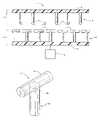
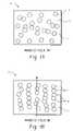
- FIG. 1when a MR fluid 2 is exposed to a magnetic field, the normally randomly oriented particles 4 within the fluid 6 form chains of particles in the direction of the magnetic field lines. The particle chains increase the apparent viscosity (flow resistance) of the fluid.
- MR elastomersare suspensions of micrometer-sized, magnetically polarizable particles in a thermoset elastic polymer or rubber.
- the stiffness of the elastomer structureis accomplished by changing the shear and compression/tension moduli by varying the strength of the applied magnetic field.
- the MR fluids and elastomerstypically develop structure when exposed to a magnetic field in as little as a few milliseconds. Discontinuing the exposure of the MR fluid or elastomers to the magnetic field reverses the process and the fluid returns to a lower viscosity state or the elastomer returns to its lower modulus state.
- MR fluids enclosed in structural elementshave been disclosed in U.S. Pat. No. 5,547,049.
- a releasable fastener systemthat provides for a controlled release or separation of a joint in a shear and/or pull-off direction.
- a releasable fastener systemcomprises a first portion comprising a first support and a plurality of first hook elements disposed on a surface, wherein the first hook elements comprise head elements at ends of the first hook elements; a second portion comprising a second support and a plurality of second hook elements disposed on a surface, wherein the second hook elements comprise head elements at ends of the second hook elements, wherein the head elements of the second hook elements comprise a material adapted to change a directional orientation of the head elements of the second hook elements upon receipt of a magnetic signal; and an activation device coupled to the plurality of the second hook elements, the activation device being operable to selectively provide the magnetic signal to the head elements of the second hook elements, wherein the magnetic signal effectuates a change in the directional orientation of the head elements of the second hook elements to reduce or increase a shear
- first hook elementsalso comprise a material adapted to change a directional orientation of the head elements of the first hook elements upon receipt of a magnetic signal.
- a process for operating a releasable fastener systemcomprises contacting a first portion to a second portion to form a releasable engagement, wherein the first portion comprises a first support and a plurality of first hook elements disposed on a surface, wherein the first hook elements comprise head elements at ends of the first hook elements; and a second portion comprising a second support and a plurality of second hook elements disposed on a surface, wherein the second hook elements comprise head elements at ends of the second hook elements, wherein the head elements of the second hook elements comprise a material adapted to change a directional orientation of the head elements of the second hook elements upon receipt of a magnetic signal; maintaining constant shear and pull-off forces in the releasable engagement; selectively introducing the magnetic signal to the head elements of the second hook elements, wherein the magnetic signal is effective to change the directional orientation of the head elements of the second hook elements; and reducing shear and/or pull-off forces in the releasable engagement.
- FIG. 1is a schematic of a magnetorheological fluid
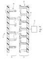
- FIG. 2is a cross sectional view of a releasable fastening system
- FIG. 4is a schematic of magnetic swivel hooks in an unlocked position
- FIG. 5is a schematic of an overhead view of magnetic swivel hooks in a locked position
- FIG. 6is a schematic of an overhead view of magnetic swivel hooks in an unlocked position
- FIG. 7is a schematic of a magnetic swivel hook, with an interior view of the hook's head.
- FIG. 8is a schematic of a magnetic swivel hook.
- a releasable fastener systemcomprises a first hook portion 12 and a second hook portion 14 .
- the first hook portion 12includes a support 16 and a plurality of closely spaced upstanding first hook elements 18 extending from one side thereof. At the ends of the first hook elements are first head elements 17 .
- the second hook portion 14includes a support 20 and a plurality of closely spaced upstanding second hook elements 22 extending from one side thereof. At the ends of the second hook elements are second head elements 21 .
- the second head elements 21are formed of a material that provide a directional orientation capability to the second head elements 21 , as will be described in greater detail.
- the second head elementsare fabricated from materials that are resilient and flexible in addition to providing a directional orientation capability.
- an activation device 24Coupled to and in operative communication with the second head elements 21 is an activation device 24 .
- the activation device 24provides an activation signal to the second head elements 21 to change the directional orientation of the second head elements 21 .
- the activation signal provided by activation device 24 for changing the directional orientation of the second head elements 21is a magnetic signal in the form of a magnetic field.
- the change in directional orientationgenerally remains for the duration of the applied activation signal.
- the second head elements 21revert substantially to a relaxed or unpowered orientation, and as such, are free to swivel about the central axis of the support.
- the illustrated releasable fastener system 10is exemplary only and is not intended to be limited to any particular shape, size, configuration, number or shape of second head elements 21 , second hook elements 22 , first head elements 17 , first hook elements 18 , or the like.
- the two portions 12 and 14are pressed together to create a joint that is relatively strong in shear and pull-off directions, and weak in a peel direction.
- the first head elements 17become engaged with the second head elements 21 and the close spacing of the hook elements 18 and 22 resists substantial lateral movement when subjected to shearing forces in the plane of engagement.
- the engaged jointis subjected to a force perpendicular to this plane, (i.e., pull-off forces)
- the interlocked first head elements 17 and second head elements 21resist substantial separation of the two portions 12 and 14 .
- the second head elements 21when the second head elements 21 are subjected to a peeling force, the second head elements 21 and the first head elements 17 can become disengaged from one another. It should be noted that separating the two portions 12 and 14 using the peeling force generally requires that one or both of the supports forming the hook portions be flexible.
- the hook elements 22may be formed integrally with support 20 , or more preferably, may be disposed on the support 20 .
- the spacing between adjacent second hook elements 22 and second head elements 21is an amount effective to provide sufficient shear and pull-off resistance desired for the particular application during engagement with first hook elements 18 and first head elements 17 .
- the amount of shear and pull-off force required for effective engagementcan vary significantly. Generally, the closer the spacing and the greater amount of hook elements employed will result in increased shear and pull-off forces upon engagement.
- the first and second head elements 17 and 21 of hook elements 18 and 22preferably have a similar shape configured to become engaged with one another upon the pressing contact of the first portion 12 with the second portion 14 .
- the activation device 24can be configured to deliver an activation signal to the second head elements, wherein the activation signal comprises a magnetic signal.
- the magnetic signalis preferably a magnetic field.
- the strength and direction of the magnetic fieldis dependent on the particular material employed for fabricating the second head elements.
- the magnetic fieldmay be generated by a permanent magnet, an electromagnet, or combinations comprising at least one of the foregoing.
- the magnitude of the applied field strength requiredis the amount needed to change a directional orientation of the second head elements to reduce or increase a shear force and/or pull-off force, depending upon the application.
- the first hook elements 18generally comprise first head elements at the ends of the hook elements.
- the first head elementsare generally oriented in substantially the same direction/orientation.
- Materials suitable for manufacturing the first hook elements and first head elementsinclude metals, thermoplastics such as polypropylene, polyethylene, polyamide, polyester, polystyrene, polyvinyl chloride, acetal, acrylic, polycarbonate, polyphenylene oxide, polyurethane, polysulfone, and the like.
- the first hook elements 18may be integrated with the support or may be attached to the support.
- the second portioncomprises a surface that contains an array of second hook elements comprising second head elements fabricated from magnetic material.
- the magnetic head elementsWhen a magnetic field is applied, the magnetic head elements orient themselves in the direction of the applied magnetic field.
- the fastener systemis “unlocked” by the orientation of the second head elements, which swivel out of the way of the first head elements.
Landscapes
- Engineering & Computer Science (AREA)
- General Engineering & Computer Science (AREA)
- Chemical & Material Sciences (AREA)
- Materials Engineering (AREA)
- Mechanical Engineering (AREA)
- Slide Fasteners, Snap Fasteners, And Hook Fasteners (AREA)
- Slide Fasteners (AREA)
Abstract
Description
Claims (28)
Priority Applications (4)
| Application Number | Priority Date | Filing Date | Title |
|---|---|---|---|
| US10/305,376US6983517B2 (en) | 2002-10-19 | 2002-11-26 | Releasable fastener system |
| JP2003358943AJP4198024B2 (en) | 2002-10-19 | 2003-10-20 | Openable fastener system |
| EP03026258AEP1424022B1 (en) | 2002-11-26 | 2003-11-14 | Releasable fastener system |
| DE60327297TDE60327297D1 (en) | 2002-11-26 | 2003-11-14 | Detachable fastening device |
Applications Claiming Priority (2)
| Application Number | Priority Date | Filing Date | Title |
|---|---|---|---|
| US10/273,691US7200902B2 (en) | 2002-10-19 | 2002-10-19 | Releasable fastener system |
| US10/305,376US6983517B2 (en) | 2002-10-19 | 2002-11-26 | Releasable fastener system |
Related Parent Applications (1)
| Application Number | Title | Priority Date | Filing Date |
|---|---|---|---|
| US10/273,691Continuation-In-PartUS7200902B2 (en) | 2002-10-19 | 2002-10-19 | Releasable fastener system |
Publications (2)
| Publication Number | Publication Date |
|---|---|
| US20040074063A1 US20040074063A1 (en) | 2004-04-22 |
| US6983517B2true US6983517B2 (en) | 2006-01-10 |
Family
ID=32298052
Family Applications (1)
| Application Number | Title | Priority Date | Filing Date |
|---|---|---|---|
| US10/305,376Expired - LifetimeUS6983517B2 (en) | 2002-10-19 | 2002-11-26 | Releasable fastener system |
Country Status (3)
| Country | Link |
|---|---|
| US (1) | US6983517B2 (en) |
| EP (1) | EP1424022B1 (en) |
| DE (1) | DE60327297D1 (en) |
Cited By (9)
| Publication number | Priority date | Publication date | Assignee | Title |
|---|---|---|---|---|
| US20090308509A1 (en)* | 2005-10-13 | 2009-12-17 | Snpe Materiaux Energetiques | Rapid Gas Generating Pyrotechnical Composition and Method for Obtaining Same |
| US20120266417A1 (en)* | 2008-03-19 | 2012-10-25 | GM Global Technology Operations LLC | Active material based fasteners including cable ties and twist ties |
| US20150068013A1 (en)* | 2013-09-10 | 2015-03-12 | Texas Instruments Incorporated | Current, temperature or electromagnetic field actuated fasteners |
| US9198483B2 (en) | 2013-03-15 | 2015-12-01 | Thomas M. Adams | Self adhering connection surfaces, straps, snaps and bands |
| USD784732S1 (en)* | 2014-12-04 | 2017-04-25 | Peter Larrieu | Inflatable spinal support device |
| US9655413B2 (en) | 2013-03-15 | 2017-05-23 | Thomas M. Adams | Self adhering connection surfaces, straps, snaps and bands |
| US20170311666A1 (en)* | 2014-12-19 | 2017-11-02 | The North Face Apparel Corp. | Magnetic closures |
| US11076660B2 (en)* | 2018-08-31 | 2021-08-03 | Lintec Of America, Inc. | Hook and loop artificial muscles |
| US12433357B1 (en) | 2024-07-03 | 2025-10-07 | Standard Textile Co., Inc. | Reusable, rear-opening protective garment with fastening elements configured to facilitate doffing-type removal |
Families Citing this family (16)
| Publication number | Priority date | Publication date | Assignee | Title |
|---|---|---|---|---|
| US7207946B2 (en)* | 2002-05-09 | 2007-04-24 | Spiration, Inc. | Automated provision of information related to air evacuation from a chest cavity |
| US7013538B2 (en) | 2002-10-19 | 2006-03-21 | General Motors Corporation | Electroactive polymer releasable fastening system and method of use |
| US6944920B2 (en)* | 2002-10-19 | 2005-09-20 | General Motors Corporation | Electrostatically releasable fastening system and method of use |
| US7032282B2 (en) | 2002-10-19 | 2006-04-25 | General Motors Corporation | Releasable fastener system |
| US7140081B2 (en)* | 2002-10-19 | 2006-11-28 | General Motors Corporation | Releasable fastener system |
| JP4015983B2 (en)* | 2002-10-19 | 2007-11-28 | ゼネラル・モーターズ・コーポレーション | Magnetorheological nanocomposite elastomer for releasable accessories |
| US6973701B2 (en)* | 2002-10-19 | 2005-12-13 | General Motors Corporation | Releasable fastening system based on ionic polymer metal composites and method of use |
| US7146690B2 (en)* | 2002-10-19 | 2006-12-12 | General Motors Corporation | Releasable fastener system |
| US7308738B2 (en)* | 2002-10-19 | 2007-12-18 | General Motors Corporation | Releasable fastener systems and processes |
| US7219113B2 (en)* | 2003-09-26 | 2007-05-15 | International Business Machines Corporation | Pseudo-random binary sequence checker with automatic synchronization |
| US20060261109A1 (en)* | 2005-05-18 | 2006-11-23 | Browne Alan L | Cargo container including an active material based releasable fastener system |
| DE102006050365A1 (en)* | 2006-10-25 | 2008-04-30 | MAX-PLANCK-Gesellschaft zur Förderung der Wissenschaften e.V. | Structured surface with switchable adhesion |
| DE102007062650B3 (en)* | 2007-12-24 | 2009-04-09 | Gottlieb Binder Gmbh & Co. Kg | Fixing system, in particular for metallic components |
| TWI537362B (en)* | 2014-11-20 | 2016-06-11 | 國立清華大學 | Biomimetic adhesive layer and manufacturing method thereof |
| CN108338551A (en)* | 2018-01-26 | 2018-07-31 | 靳月华 | A kind of bull stick for holder connection |
| CN110319143A (en)* | 2019-07-12 | 2019-10-11 | 吉林建筑大学 | A kind of dismountable bumping post |
Citations (105)
| Publication number | Priority date | Publication date | Assignee | Title |
|---|---|---|---|---|
| US2717437A (en) | 1951-10-22 | 1955-09-13 | Velcro Sa Soulie | Velvet type fabric and method of producing same |
| US2994117A (en) | 1958-01-31 | 1961-08-01 | Mcmullin Harold Breniman | Opening closure means |
| US3101517A (en) | 1960-11-28 | 1963-08-27 | Fox Marvin | Fastener |
| US3128514A (en) | 1959-04-03 | 1964-04-14 | Parker Pen Co | Writing instrument releasable securing means |
| US3138749A (en) | 1962-03-05 | 1964-06-23 | George R Stibitz | Incremental feed mechanisms |
| US3176364A (en) | 1959-10-06 | 1965-04-06 | Dritz Arthur | Separable fastener |
| US3292019A (en) | 1963-11-01 | 1966-12-13 | Bendix Corp | Transducer |
| US3365757A (en) | 1964-10-13 | 1968-01-30 | Billarant Jean | Flexible band fitted with hooked elements of the filament type |
| US3469289A (en)* | 1969-02-06 | 1969-09-30 | Nasa | Quick release hook tape |
| US3490107A (en)* | 1967-10-16 | 1970-01-20 | George C Brumlik | Hook-like fastening assembly |
| US3808648A (en) | 1970-12-04 | 1974-05-07 | Velcro France | Separable fastening sheet |
| US4169303A (en) | 1976-11-24 | 1979-10-02 | Lemelson Jerome H | Fastening materials |
| US4382243A (en) | 1980-08-20 | 1983-05-03 | Robert Bosch Gmbh | Electromagnetic positioning device with piezo-electric control |
| US4391147A (en) | 1980-03-19 | 1983-07-05 | Hans List | Transducer device for measuring mechanical values on hollow bodies |
| US4634636A (en) | 1983-12-13 | 1987-01-06 | Asahi Kasei Kogyo Kabushiki Kaisha | Polyacetylene composite |
| US4637944A (en) | 1985-03-19 | 1987-01-20 | Monsanto Company | Process and device for temporarily holding and releasing objects |
| US4642254A (en) | 1985-03-19 | 1987-02-10 | Monsanto Company | Process and device for temporarily holding and releasing objects |
| US4693921A (en) | 1983-12-13 | 1987-09-15 | Aplix | Fastening tape designed to be attached to a molded article during molding, and its attaching method |
| US4752537A (en) | 1985-06-10 | 1988-06-21 | The Boeing Company | Metal matrix composite fiber reinforced weld |
| US4775310A (en) | 1984-04-16 | 1988-10-04 | Velcro Industries B.V. | Apparatus for making a separable fastener |
| US4794028A (en)* | 1984-04-16 | 1988-12-27 | Velcro Industries B.V. | Method for continuously producing a multi-hook fastner member and product of the method |
| JPH01162587A (en) | 1987-12-19 | 1989-06-27 | Kawasaki Heavy Ind Ltd | Laser welding method |
| US4931344A (en) | 1987-12-15 | 1990-06-05 | Kuraray Company, Ltd. | Fastener component |
| EP0385443A2 (en) | 1989-02-28 | 1990-09-05 | Daikin Industries, Limited | Polymer material having shape memory characteristics |
| US5037178A (en) | 1988-12-22 | 1991-08-06 | Kingston Technologies, L.P. | Amorphous memory polymer alignment device |
| US5071363A (en) | 1990-04-18 | 1991-12-10 | Minnesota Mining And Manufacturing Company | Miniature multiple conductor electrical connector |
| US5133112A (en) | 1991-04-25 | 1992-07-28 | Gomez Acevedo Hector H | Closure device |
| US5136201A (en) | 1990-04-27 | 1992-08-04 | Rockwell International Corporation | Piezoelectric robotic articulation |
| JPH04266970A (en) | 1991-02-20 | 1992-09-22 | Toyota Central Res & Dev Lab Inc | Elastic modulus-variable material |
| JPH04314446A (en) | 1990-04-06 | 1992-11-05 | Natl Res Dev Corp | Oral fluid intake apparatus |
| US5182484A (en) | 1991-06-10 | 1993-01-26 | Rockwell International Corporation | Releasing linear actuator |
| US5191166A (en) | 1991-06-10 | 1993-03-02 | Foster-Miller, Inc. | Survivability enhancement |
| US5212855A (en) | 1991-08-05 | 1993-05-25 | Mcganty Leo F | Multiple button closure-fastener |
| US5284330A (en) | 1992-06-18 | 1994-02-08 | Lord Corporation | Magnetorheological fluid devices |
| US5312456A (en) | 1991-01-31 | 1994-05-17 | Carnegie Mellon University | Micromechanical barb and method for making the same |
| US5319257A (en) | 1992-07-13 | 1994-06-07 | Martin Marietta Energy Systems, Inc. | Unitaxial constant velocity microactuator |
| US5328337A (en) | 1990-08-17 | 1994-07-12 | Kunta Norbert J | Guided vanes hydraulic power system |
| EP0673709A1 (en) | 1994-03-25 | 1995-09-27 | Fujikura Kasei Co., Ltd. | Machine tool damping apparatus |
| US5474227A (en) | 1993-06-24 | 1995-12-12 | The Idod Trust | Method of forming seamed metal tube |
| US5486676A (en) | 1994-11-14 | 1996-01-23 | General Electric Company | Coaxial single point powder feed nozzle |
| US5492534A (en) | 1990-04-02 | 1996-02-20 | Pharmetrix Corporation | Controlled release portable pump |
| US5497861A (en) | 1994-06-27 | 1996-03-12 | Brotz; Gregory R. | Variable motion dampener |
| US5547049A (en) | 1994-05-31 | 1996-08-20 | Lord Corporation | Magnetorheological fluid composite structures |
| JPH08260748A (en) | 1995-03-28 | 1996-10-08 | Toda Constr Co Ltd | Variable viscoelastic damping device |
| US5611122A (en) | 1993-07-28 | 1997-03-18 | Minnesota Mining And Manufacturing | Interengaging fastener having reduced noise generation |
| US5656351A (en) | 1996-01-16 | 1997-08-12 | Velcro Industries B.V. | Hook and loop fastener including an epoxy binder |
| US5657516A (en) | 1995-10-12 | 1997-08-19 | Minnesota Mining And Manufacturing Company | Dual structured fastener elements |
| US5669120A (en) | 1995-05-09 | 1997-09-23 | Ykk Corporation | Molded surface fastener |
| US5671498A (en) | 1995-04-04 | 1997-09-30 | Martin; Timothy J. | Scrubbing device |
| US5712524A (en) | 1994-12-27 | 1998-01-27 | Nec Corporation | Piezoelectric rotation driving apparatus |
| US5725928A (en) | 1995-02-17 | 1998-03-10 | Velcro Industries B.V. | Touch fastener with magnetic attractant |
| US5797170A (en) | 1996-03-04 | 1998-08-25 | Ykk Corporation | Synthetic resin molded surface fastener |
| US5798188A (en) | 1997-06-25 | 1998-08-25 | E. I. Dupont De Nemours And Company | Polymer electrolyte membrane fuel cell with bipolar plate having molded polymer projections |
| US5814999A (en) | 1997-05-27 | 1998-09-29 | Ford Global Technologies, Inc. | Method and apparatus for measuring displacement and force |
| US5816587A (en) | 1996-07-23 | 1998-10-06 | Ford Global Technologies, Inc. | Method and apparatus for reducing brake shudder |
| US5817380A (en) | 1996-04-12 | 1998-10-06 | Idemitsu Petrochemical Co., Ltd. | Snap-zipper and bag with the same |
| US5885652A (en) | 1995-11-13 | 1999-03-23 | Corning Incorporated | Method and apparatus for coating optical fibers |
| WO1999042528A2 (en) | 1998-02-23 | 1999-08-26 | Mnemoscience Gmbh | Shape memory polymers |
| US5945193A (en)* | 1995-12-06 | 1999-08-31 | Velcro Industries B.V. | Touch fastener with porous metal containing layer |
| US5969518A (en) | 1996-10-28 | 1999-10-19 | Fag Automobiltechnik Ag | Antifriction mounting having a rotational-speed measuring device protected from contamination |
| US5974856A (en) | 1997-05-27 | 1999-11-02 | Ford Global Technologies, Inc. | Method for allowing rapid evaluation of chassis elastomeric devices in motor vehicles |
| US5979744A (en) | 1998-03-25 | 1999-11-09 | Brigleb; Mary Beth | Object wrapping and method of wrapping an object |
| US5983467A (en) | 1996-12-30 | 1999-11-16 | Duffy; Leonard A. | Interlocking device |
| US6029783A (en) | 1998-04-16 | 2000-02-29 | Wirthlin; Alvin R. | Variable resistance device using electroactive fluid |
| US6086599A (en) | 1999-02-08 | 2000-07-11 | The Regents Of The University Of California | Micro devices using shape memory polymer patches for mated connections |
| US6102933A (en) | 1997-02-28 | 2000-08-15 | The Regents Of The University Of California | Release mechanism utilizing shape memory polymer material |
| US6102912A (en) | 1997-05-29 | 2000-08-15 | Sofamor S.N.C. | Vertebral rod of constant section for spinal osteosynthesis instrumentations |
| WO2000062637A1 (en) | 1999-04-20 | 2000-10-26 | Daimlerchrysler Ag | Releasable closure |
| US6148487A (en) | 1998-11-19 | 2000-11-21 | Aplix | Laminated self-gripping tape, molded product, and method of manufacturing a molded article including a self-gripping tape |
| US6156842A (en) | 1998-03-11 | 2000-12-05 | The Dow Chemical Company | Structures and fabricated articles having shape memory made from α-olefin/vinyl or vinylidene aromatic and/or hindered aliphatic vinyl or vinylidene interpolymers |
| US6203717B1 (en) | 1999-07-01 | 2001-03-20 | Lord Corporation | Stable magnetorheological fluids |
| DE19956011A1 (en) | 1999-11-20 | 2001-06-21 | Binder Gottlieb Gmbh & Co | Fastener part |
| US6257133B1 (en) | 1999-03-15 | 2001-07-10 | International Paper | Method and apparatus for controlling cross directional nip dynamics |
| US20010040819A1 (en) | 2000-01-07 | 2001-11-15 | Hidekazu Hayashi | Magnetoresistive device and magnetic memory using the same |
| US20020007884A1 (en) | 2000-06-29 | 2002-01-24 | Andreas Schuster | Semifinished product made from a shape memory alloy having a two-way effect and method for manufacturing the same |
| WO2001084002A3 (en) | 2000-05-03 | 2002-03-21 | Univ Michigan | Attachment mechanism |
| US20020050045A1 (en) | 1996-12-09 | 2002-05-02 | Chiodo Joseph David | Method for disassembling different elements |
| US20020076520A1 (en) | 2000-12-14 | 2002-06-20 | Neeb Alexander J. | Magnetic fastening system |
| US20020086152A1 (en)* | 1999-11-04 | 2002-07-04 | Gambino Richard J. | Thermally sprayed, flexible magnet with an induced anisotropy |
| US6454923B1 (en) | 1997-11-10 | 2002-09-24 | Central Research Laboratories Limited | Gas sensor |
| US20020142119A1 (en) | 2001-03-27 | 2002-10-03 | The Regents Of The University Of California | Shape memory alloy/shape memory polymer tools |
| US6460230B2 (en) | 2000-01-12 | 2002-10-08 | Kuraray Co., Ltd. | Mold-in fastening member and production of molded resin article having mold-in fastening member |
| US6502290B1 (en) | 2001-07-19 | 2003-01-07 | Taiwan Paiho Limited | Hook tape fabrication method |
| WO2002045536A3 (en) | 2000-12-08 | 2003-01-30 | Binder Gottlieb Gmbh & Co | Hook-and-loop fastener produced from a shape memory plastic material |
| US6544245B2 (en) | 2001-05-10 | 2003-04-08 | Velcro Industries B.V. | Bi-stable fastening |
| US20030120300A1 (en) | 2001-12-20 | 2003-06-26 | Scimed Life Systems, Inc. | Detachable device with electrically responsive element |
| US6593540B1 (en) | 2002-02-08 | 2003-07-15 | Honeywell International, Inc. | Hand held powder-fed laser fusion welding torch |
| US6598274B1 (en)* | 2002-04-11 | 2003-07-29 | Koninklijke Philips Electronics N.V. | Electrically releasable hook and loop fastener |
| US6605795B1 (en) | 1999-11-04 | 2003-08-12 | Mts Systems Corporation | Control system for depositing powder to a molten puddle |
| US6681849B2 (en) | 2001-08-22 | 2004-01-27 | Baker Hughes Incorporated | Downhole packer system utilizing electroactive polymers |
| US20040025639A1 (en) | 2002-08-09 | 2004-02-12 | Dr. Mohsen Shahinpoor | Novel electrically active ionic polymer metal composites and novel methods of manufacturing them |
| US20040074064A1 (en) | 2002-10-19 | 2004-04-22 | Powell Bob Ross | Releasable fastener system |
| US20040074068A1 (en) | 2002-10-19 | 2004-04-22 | Browne Alan Lampe | Releasable fastener system |
| US20040074070A1 (en) | 2002-10-19 | 2004-04-22 | Momoda Leslie A. | Releasable fastening system based on ionic polymer metal composites and method of use |
| US20040074069A1 (en) | 2002-10-19 | 2004-04-22 | Browne Alan Lampe | Electroactive polymer releasable fastening system and method of use |
| US20040074071A1 (en) | 2002-10-19 | 2004-04-22 | Golden Mark A. | Releasable fastener systems and processes |
| US20040074067A1 (en) | 2002-10-19 | 2004-04-22 | Browne Alan Lampe | Electrostatically releasable fastening system and method of use |
| US20040074061A1 (en) | 2002-10-19 | 2004-04-22 | Ottaviani Robert A. | Magnetorheological nanocomposite elastomer for releasable attachment applications |
| US20040074062A1 (en) | 2002-10-19 | 2004-04-22 | Stanford Thomas B. | Releasable fastener system |
| US6740094B2 (en) | 2000-11-06 | 2004-05-25 | The Regents Of The University Of California | Shape memory polymer actuator and catheter |
| US6742227B2 (en) | 2002-10-19 | 2004-06-01 | General Motors Corporation | Releasable fastener system and process |
| US20040117955A1 (en) | 2002-10-19 | 2004-06-24 | William Barvosa-Carter | Releasable fastener systems and processes |
| US6766566B2 (en) | 2002-10-19 | 2004-07-27 | General Motors Corporation | Releasable fastener system |
| US6797914B2 (en) | 2003-02-05 | 2004-09-28 | General Motors Corporation | Joining workpieces by laser welding with powder injection |
| US6815873B2 (en) | 2002-10-19 | 2004-11-09 | General Motors Corporation | Releasable fastener system |
Family Cites Families (2)
| Publication number | Priority date | Publication date | Assignee | Title |
|---|---|---|---|---|
| JP2004045184A (en)* | 2002-07-11 | 2004-02-12 | Denso Corp | Semiconductor dynamics quantity sensor |
| US7200902B2 (en)* | 2002-10-19 | 2007-04-10 | General Motors Corporation | Releasable fastener system |
- 2002
- 2002-11-26USUS10/305,376patent/US6983517B2/ennot_activeExpired - Lifetime
- 2003
- 2003-11-14EPEP03026258Apatent/EP1424022B1/ennot_activeExpired - Lifetime
- 2003-11-14DEDE60327297Tpatent/DE60327297D1/ennot_activeExpired - Lifetime
Patent Citations (110)
| Publication number | Priority date | Publication date | Assignee | Title |
|---|---|---|---|---|
| US2717437A (en) | 1951-10-22 | 1955-09-13 | Velcro Sa Soulie | Velvet type fabric and method of producing same |
| US2994117A (en) | 1958-01-31 | 1961-08-01 | Mcmullin Harold Breniman | Opening closure means |
| US3128514A (en) | 1959-04-03 | 1964-04-14 | Parker Pen Co | Writing instrument releasable securing means |
| US3176364A (en) | 1959-10-06 | 1965-04-06 | Dritz Arthur | Separable fastener |
| US3101517A (en) | 1960-11-28 | 1963-08-27 | Fox Marvin | Fastener |
| US3138749A (en) | 1962-03-05 | 1964-06-23 | George R Stibitz | Incremental feed mechanisms |
| US3292019A (en) | 1963-11-01 | 1966-12-13 | Bendix Corp | Transducer |
| US3365757A (en) | 1964-10-13 | 1968-01-30 | Billarant Jean | Flexible band fitted with hooked elements of the filament type |
| US3490107A (en)* | 1967-10-16 | 1970-01-20 | George C Brumlik | Hook-like fastening assembly |
| US3469289A (en)* | 1969-02-06 | 1969-09-30 | Nasa | Quick release hook tape |
| US3808648A (en) | 1970-12-04 | 1974-05-07 | Velcro France | Separable fastening sheet |
| US4169303A (en) | 1976-11-24 | 1979-10-02 | Lemelson Jerome H | Fastening materials |
| US4391147A (en) | 1980-03-19 | 1983-07-05 | Hans List | Transducer device for measuring mechanical values on hollow bodies |
| US4382243A (en) | 1980-08-20 | 1983-05-03 | Robert Bosch Gmbh | Electromagnetic positioning device with piezo-electric control |
| US4634636A (en) | 1983-12-13 | 1987-01-06 | Asahi Kasei Kogyo Kabushiki Kaisha | Polyacetylene composite |
| US4693921A (en) | 1983-12-13 | 1987-09-15 | Aplix | Fastening tape designed to be attached to a molded article during molding, and its attaching method |
| US4775310A (en) | 1984-04-16 | 1988-10-04 | Velcro Industries B.V. | Apparatus for making a separable fastener |
| US4794028A (en)* | 1984-04-16 | 1988-12-27 | Velcro Industries B.V. | Method for continuously producing a multi-hook fastner member and product of the method |
| US4642254A (en) | 1985-03-19 | 1987-02-10 | Monsanto Company | Process and device for temporarily holding and releasing objects |
| US4637944A (en) | 1985-03-19 | 1987-01-20 | Monsanto Company | Process and device for temporarily holding and releasing objects |
| US4752537A (en) | 1985-06-10 | 1988-06-21 | The Boeing Company | Metal matrix composite fiber reinforced weld |
| US4931344A (en) | 1987-12-15 | 1990-06-05 | Kuraray Company, Ltd. | Fastener component |
| JPH01162587A (en) | 1987-12-19 | 1989-06-27 | Kawasaki Heavy Ind Ltd | Laser welding method |
| US5037178A (en) | 1988-12-22 | 1991-08-06 | Kingston Technologies, L.P. | Amorphous memory polymer alignment device |
| EP0385443A2 (en) | 1989-02-28 | 1990-09-05 | Daikin Industries, Limited | Polymer material having shape memory characteristics |
| US5492534A (en) | 1990-04-02 | 1996-02-20 | Pharmetrix Corporation | Controlled release portable pump |
| JPH04314446A (en) | 1990-04-06 | 1992-11-05 | Natl Res Dev Corp | Oral fluid intake apparatus |
| US5071363A (en) | 1990-04-18 | 1991-12-10 | Minnesota Mining And Manufacturing Company | Miniature multiple conductor electrical connector |
| US5136201A (en) | 1990-04-27 | 1992-08-04 | Rockwell International Corporation | Piezoelectric robotic articulation |
| US5328337A (en) | 1990-08-17 | 1994-07-12 | Kunta Norbert J | Guided vanes hydraulic power system |
| US5312456A (en) | 1991-01-31 | 1994-05-17 | Carnegie Mellon University | Micromechanical barb and method for making the same |
| JPH04266970A (en) | 1991-02-20 | 1992-09-22 | Toyota Central Res & Dev Lab Inc | Elastic modulus-variable material |
| US5133112A (en) | 1991-04-25 | 1992-07-28 | Gomez Acevedo Hector H | Closure device |
| US5182484A (en) | 1991-06-10 | 1993-01-26 | Rockwell International Corporation | Releasing linear actuator |
| US5191166A (en) | 1991-06-10 | 1993-03-02 | Foster-Miller, Inc. | Survivability enhancement |
| US5212855A (en) | 1991-08-05 | 1993-05-25 | Mcganty Leo F | Multiple button closure-fastener |
| US5284330A (en) | 1992-06-18 | 1994-02-08 | Lord Corporation | Magnetorheological fluid devices |
| US5319257A (en) | 1992-07-13 | 1994-06-07 | Martin Marietta Energy Systems, Inc. | Unitaxial constant velocity microactuator |
| US5474227A (en) | 1993-06-24 | 1995-12-12 | The Idod Trust | Method of forming seamed metal tube |
| US5611122A (en) | 1993-07-28 | 1997-03-18 | Minnesota Mining And Manufacturing | Interengaging fastener having reduced noise generation |
| EP0673709A1 (en) | 1994-03-25 | 1995-09-27 | Fujikura Kasei Co., Ltd. | Machine tool damping apparatus |
| US5547049A (en) | 1994-05-31 | 1996-08-20 | Lord Corporation | Magnetorheological fluid composite structures |
| US5497861A (en) | 1994-06-27 | 1996-03-12 | Brotz; Gregory R. | Variable motion dampener |
| US5486676A (en) | 1994-11-14 | 1996-01-23 | General Electric Company | Coaxial single point powder feed nozzle |
| US5712524A (en) | 1994-12-27 | 1998-01-27 | Nec Corporation | Piezoelectric rotation driving apparatus |
| US6129970A (en)* | 1995-02-17 | 2000-10-10 | Velcro Industries B.V. | Touch fastener with magnetic attractant and molded article containing same |
| US5725928A (en) | 1995-02-17 | 1998-03-10 | Velcro Industries B.V. | Touch fastener with magnetic attractant |
| JPH08260748A (en) | 1995-03-28 | 1996-10-08 | Toda Constr Co Ltd | Variable viscoelastic damping device |
| US5671498A (en) | 1995-04-04 | 1997-09-30 | Martin; Timothy J. | Scrubbing device |
| US5669120A (en) | 1995-05-09 | 1997-09-23 | Ykk Corporation | Molded surface fastener |
| US5657516A (en) | 1995-10-12 | 1997-08-19 | Minnesota Mining And Manufacturing Company | Dual structured fastener elements |
| US5885652A (en) | 1995-11-13 | 1999-03-23 | Corning Incorporated | Method and apparatus for coating optical fibers |
| US5945193A (en)* | 1995-12-06 | 1999-08-31 | Velcro Industries B.V. | Touch fastener with porous metal containing layer |
| US5656351A (en) | 1996-01-16 | 1997-08-12 | Velcro Industries B.V. | Hook and loop fastener including an epoxy binder |
| US5797170A (en) | 1996-03-04 | 1998-08-25 | Ykk Corporation | Synthetic resin molded surface fastener |
| US5817380A (en) | 1996-04-12 | 1998-10-06 | Idemitsu Petrochemical Co., Ltd. | Snap-zipper and bag with the same |
| US5816587A (en) | 1996-07-23 | 1998-10-06 | Ford Global Technologies, Inc. | Method and apparatus for reducing brake shudder |
| US5969518A (en) | 1996-10-28 | 1999-10-19 | Fag Automobiltechnik Ag | Antifriction mounting having a rotational-speed measuring device protected from contamination |
| US20020062547A1 (en) | 1996-12-09 | 2002-05-30 | Joseph David Chiodo | Method for disassembling different elements |
| US20020050045A1 (en) | 1996-12-09 | 2002-05-02 | Chiodo Joseph David | Method for disassembling different elements |
| US5983467A (en) | 1996-12-30 | 1999-11-16 | Duffy; Leonard A. | Interlocking device |
| US6102933A (en) | 1997-02-28 | 2000-08-15 | The Regents Of The University Of California | Release mechanism utilizing shape memory polymer material |
| US5814999A (en) | 1997-05-27 | 1998-09-29 | Ford Global Technologies, Inc. | Method and apparatus for measuring displacement and force |
| US5974856A (en) | 1997-05-27 | 1999-11-02 | Ford Global Technologies, Inc. | Method for allowing rapid evaluation of chassis elastomeric devices in motor vehicles |
| US6102912A (en) | 1997-05-29 | 2000-08-15 | Sofamor S.N.C. | Vertebral rod of constant section for spinal osteosynthesis instrumentations |
| US5798188A (en) | 1997-06-25 | 1998-08-25 | E. I. Dupont De Nemours And Company | Polymer electrolyte membrane fuel cell with bipolar plate having molded polymer projections |
| US6454923B1 (en) | 1997-11-10 | 2002-09-24 | Central Research Laboratories Limited | Gas sensor |
| WO1999042528A2 (en) | 1998-02-23 | 1999-08-26 | Mnemoscience Gmbh | Shape memory polymers |
| US6388043B1 (en) | 1998-02-23 | 2002-05-14 | Mnemoscience Gmbh | Shape memory polymers |
| US6156842A (en) | 1998-03-11 | 2000-12-05 | The Dow Chemical Company | Structures and fabricated articles having shape memory made from α-olefin/vinyl or vinylidene aromatic and/or hindered aliphatic vinyl or vinylidene interpolymers |
| US5979744A (en) | 1998-03-25 | 1999-11-09 | Brigleb; Mary Beth | Object wrapping and method of wrapping an object |
| US6029783A (en) | 1998-04-16 | 2000-02-29 | Wirthlin; Alvin R. | Variable resistance device using electroactive fluid |
| US6148487A (en) | 1998-11-19 | 2000-11-21 | Aplix | Laminated self-gripping tape, molded product, and method of manufacturing a molded article including a self-gripping tape |
| US6086599A (en) | 1999-02-08 | 2000-07-11 | The Regents Of The University Of California | Micro devices using shape memory polymer patches for mated connections |
| US6257133B1 (en) | 1999-03-15 | 2001-07-10 | International Paper | Method and apparatus for controlling cross directional nip dynamics |
| US6546602B1 (en)* | 1999-04-20 | 2003-04-15 | Daimlerchrysler Ag | Releasable closure |
| WO2000062637A1 (en) | 1999-04-20 | 2000-10-26 | Daimlerchrysler Ag | Releasable closure |
| US6203717B1 (en) | 1999-07-01 | 2001-03-20 | Lord Corporation | Stable magnetorheological fluids |
| US6605795B1 (en) | 1999-11-04 | 2003-08-12 | Mts Systems Corporation | Control system for depositing powder to a molten puddle |
| US20020086152A1 (en)* | 1999-11-04 | 2002-07-04 | Gambino Richard J. | Thermally sprayed, flexible magnet with an induced anisotropy |
| DE19956011A1 (en) | 1999-11-20 | 2001-06-21 | Binder Gottlieb Gmbh & Co | Fastener part |
| US20010040819A1 (en) | 2000-01-07 | 2001-11-15 | Hidekazu Hayashi | Magnetoresistive device and magnetic memory using the same |
| US6460230B2 (en) | 2000-01-12 | 2002-10-08 | Kuraray Co., Ltd. | Mold-in fastening member and production of molded resin article having mold-in fastening member |
| WO2001084002A3 (en) | 2000-05-03 | 2002-03-21 | Univ Michigan | Attachment mechanism |
| US20020007884A1 (en) | 2000-06-29 | 2002-01-24 | Andreas Schuster | Semifinished product made from a shape memory alloy having a two-way effect and method for manufacturing the same |
| US6740094B2 (en) | 2000-11-06 | 2004-05-25 | The Regents Of The University Of California | Shape memory polymer actuator and catheter |
| WO2002045536A3 (en) | 2000-12-08 | 2003-01-30 | Binder Gottlieb Gmbh & Co | Hook-and-loop fastener produced from a shape memory plastic material |
| US20040033336A1 (en) | 2000-12-08 | 2004-02-19 | Axel Schulte | Hook-and-loop fastener produced from a shape memory plastic material |
| US20020076520A1 (en) | 2000-12-14 | 2002-06-20 | Neeb Alexander J. | Magnetic fastening system |
| US20020142119A1 (en) | 2001-03-27 | 2002-10-03 | The Regents Of The University Of California | Shape memory alloy/shape memory polymer tools |
| US6544245B2 (en) | 2001-05-10 | 2003-04-08 | Velcro Industries B.V. | Bi-stable fastening |
| US6502290B1 (en) | 2001-07-19 | 2003-01-07 | Taiwan Paiho Limited | Hook tape fabrication method |
| US6681849B2 (en) | 2001-08-22 | 2004-01-27 | Baker Hughes Incorporated | Downhole packer system utilizing electroactive polymers |
| US20030120300A1 (en) | 2001-12-20 | 2003-06-26 | Scimed Life Systems, Inc. | Detachable device with electrically responsive element |
| US6593540B1 (en) | 2002-02-08 | 2003-07-15 | Honeywell International, Inc. | Hand held powder-fed laser fusion welding torch |
| US6598274B1 (en)* | 2002-04-11 | 2003-07-29 | Koninklijke Philips Electronics N.V. | Electrically releasable hook and loop fastener |
| US20040025639A1 (en) | 2002-08-09 | 2004-02-12 | Dr. Mohsen Shahinpoor | Novel electrically active ionic polymer metal composites and novel methods of manufacturing them |
| US20040074061A1 (en) | 2002-10-19 | 2004-04-22 | Ottaviani Robert A. | Magnetorheological nanocomposite elastomer for releasable attachment applications |
| US20040074070A1 (en) | 2002-10-19 | 2004-04-22 | Momoda Leslie A. | Releasable fastening system based on ionic polymer metal composites and method of use |
| US20040074069A1 (en) | 2002-10-19 | 2004-04-22 | Browne Alan Lampe | Electroactive polymer releasable fastening system and method of use |
| US20040074071A1 (en) | 2002-10-19 | 2004-04-22 | Golden Mark A. | Releasable fastener systems and processes |
| US20040074067A1 (en) | 2002-10-19 | 2004-04-22 | Browne Alan Lampe | Electrostatically releasable fastening system and method of use |
| US20040074068A1 (en) | 2002-10-19 | 2004-04-22 | Browne Alan Lampe | Releasable fastener system |
| US20040074062A1 (en) | 2002-10-19 | 2004-04-22 | Stanford Thomas B. | Releasable fastener system |
| US20040074064A1 (en) | 2002-10-19 | 2004-04-22 | Powell Bob Ross | Releasable fastener system |
| US6742227B2 (en) | 2002-10-19 | 2004-06-01 | General Motors Corporation | Releasable fastener system and process |
| US20040117955A1 (en) | 2002-10-19 | 2004-06-24 | William Barvosa-Carter | Releasable fastener systems and processes |
| US6766566B2 (en) | 2002-10-19 | 2004-07-27 | General Motors Corporation | Releasable fastener system |
| US6815873B2 (en) | 2002-10-19 | 2004-11-09 | General Motors Corporation | Releasable fastener system |
| US6797914B2 (en) | 2003-02-05 | 2004-09-28 | General Motors Corporation | Joining workpieces by laser welding with powder injection |
Cited By (13)
| Publication number | Priority date | Publication date | Assignee | Title |
|---|---|---|---|---|
| US20090308509A1 (en)* | 2005-10-13 | 2009-12-17 | Snpe Materiaux Energetiques | Rapid Gas Generating Pyrotechnical Composition and Method for Obtaining Same |
| US20120266417A1 (en)* | 2008-03-19 | 2012-10-25 | GM Global Technology Operations LLC | Active material based fasteners including cable ties and twist ties |
| US9655413B2 (en) | 2013-03-15 | 2017-05-23 | Thomas M. Adams | Self adhering connection surfaces, straps, snaps and bands |
| US9198483B2 (en) | 2013-03-15 | 2015-12-01 | Thomas M. Adams | Self adhering connection surfaces, straps, snaps and bands |
| US9277789B2 (en)* | 2013-09-10 | 2016-03-08 | Texas Instruments Incorporated | Current, temperature or electromagnetic field actuated fasteners |
| US20150068013A1 (en)* | 2013-09-10 | 2015-03-12 | Texas Instruments Incorporated | Current, temperature or electromagnetic field actuated fasteners |
| US10016024B2 (en) | 2013-09-10 | 2018-07-10 | Texas Instruments Incorporated | Current, temperature or electromagnetic actuated fasteners |
| USD784732S1 (en)* | 2014-12-04 | 2017-04-25 | Peter Larrieu | Inflatable spinal support device |
| US20170311666A1 (en)* | 2014-12-19 | 2017-11-02 | The North Face Apparel Corp. | Magnetic closures |
| EP3234961A4 (en)* | 2014-12-19 | 2018-05-23 | The North Face Apparel Corp. | Magnetic closures |
| US10334900B2 (en) | 2014-12-19 | 2019-07-02 | The North Face Apparel Corp. | Magnetic closures |
| US11076660B2 (en)* | 2018-08-31 | 2021-08-03 | Lintec Of America, Inc. | Hook and loop artificial muscles |
| US12433357B1 (en) | 2024-07-03 | 2025-10-07 | Standard Textile Co., Inc. | Reusable, rear-opening protective garment with fastening elements configured to facilitate doffing-type removal |
Also Published As
| Publication number | Publication date |
|---|---|
| EP1424022A2 (en) | 2004-06-02 |
| DE60327297D1 (en) | 2009-06-04 |
| US20040074063A1 (en) | 2004-04-22 |
| EP1424022B1 (en) | 2009-04-22 |
| EP1424022A3 (en) | 2005-08-03 |
Similar Documents
| Publication | Publication Date | Title |
|---|---|---|
| US6983517B2 (en) | Releasable fastener system | |
| US6742227B2 (en) | Releasable fastener system and process | |
| US7430788B2 (en) | Magnetorheological nanocomposite elastomer for releasable attachment applications | |
| US6877193B2 (en) | Magnetorheological nanocomposite elastomer for releasable attachment applications | |
| Hajalilou et al. | Field responsive fluids as smart materials | |
| EP1279175B1 (en) | Magnetorheological composition | |
| DE112015001563T5 (en) | Modified magnetic fluid and gripping mechanism and gripping device using this modified magnetic fluid | |
| US9279527B2 (en) | Magnetic capping device and method | |
| DE102008021679A1 (en) | Adaptive object holder made of an active material | |
| KR20050055018A (en) | Magnetorheological composition and device | |
| US9505348B1 (en) | Variable magnetic break-away mounting mechanism | |
| CA2608928A1 (en) | Magnetic coupling for sprayheads | |
| JP2004506293A (en) | Ferromagnetic resonance excitation and its use for heating particle-filled substrates | |
| US9004551B2 (en) | Latchable or lockable device | |
| US20090159624A1 (en) | Roof rack features enabled by active materials | |
| DE102012202418A1 (en) | Adaptive locking and releasing device and their use for the controlled blocking or release of movable components | |
| CN109390185A (en) | Permanent magnet contactor | |
| WO2022152418A1 (en) | Magnetic-mechanical closure device | |
| JP4198024B2 (en) | Openable fastener system | |
| US8551576B2 (en) | Method for controlling a coefficient of friction | |
| JP4085042B2 (en) | Releasable fastener system and process | |
| Goodfriend et al. | Application of a magnetostrictive alloy, terfenol-D to direct control of hydraulic valves | |
| Hajalilou et al. | Magnetorheological (MR) fluids | |
| US20180281847A1 (en) | Autopilot enabling device | |
| CN105916789A (en) | Spool fixation device with bi-stable magnet assemblies |
Legal Events
| Date | Code | Title | Description |
|---|---|---|---|
| AS | Assignment | Owner name:GENERAL MOTORS CORPORATION, MICHIGAN Free format text:ASSIGNMENT OF ASSIGNORS INTEREST;ASSIGNORS:GOLDEN, MARK A.;ULICNY, JOHN C.;REEL/FRAME:013850/0335 Effective date:20030124 | |
| STCF | Information on status: patent grant | Free format text:PATENTED CASE | |
| AS | Assignment | Owner name:GM GLOBAL TECHNOLOGY OPERATIONS, INC., MICHIGAN Free format text:ASSIGNMENT OF ASSIGNORS INTEREST;ASSIGNOR:GENERAL MOTORS CORPORATION;REEL/FRAME:022117/0047 Effective date:20050119 Owner name:GM GLOBAL TECHNOLOGY OPERATIONS, INC.,MICHIGAN Free format text:ASSIGNMENT OF ASSIGNORS INTEREST;ASSIGNOR:GENERAL MOTORS CORPORATION;REEL/FRAME:022117/0047 Effective date:20050119 | |
| AS | Assignment | Owner name:UNITED STATES DEPARTMENT OF THE TREASURY, DISTRICT Free format text:SECURITY AGREEMENT;ASSIGNOR:GM GLOBAL TECHNOLOGY OPERATIONS, INC.;REEL/FRAME:022201/0547 Effective date:20081231 Owner name:UNITED STATES DEPARTMENT OF THE TREASURY,DISTRICT Free format text:SECURITY AGREEMENT;ASSIGNOR:GM GLOBAL TECHNOLOGY OPERATIONS, INC.;REEL/FRAME:022201/0547 Effective date:20081231 | |
| AS | Assignment | Owner name:CITICORP USA, INC. AS AGENT FOR BANK PRIORITY SECU Free format text:SECURITY AGREEMENT;ASSIGNOR:GM GLOBAL TECHNOLOGY OPERATIONS, INC.;REEL/FRAME:022553/0399 Effective date:20090409 Owner name:CITICORP USA, INC. AS AGENT FOR HEDGE PRIORITY SEC Free format text:SECURITY AGREEMENT;ASSIGNOR:GM GLOBAL TECHNOLOGY OPERATIONS, INC.;REEL/FRAME:022553/0399 Effective date:20090409 | |
| FPAY | Fee payment | Year of fee payment:4 | |
| AS | Assignment | Owner name:GM GLOBAL TECHNOLOGY OPERATIONS, INC., MICHIGAN Free format text:RELEASE BY SECURED PARTY;ASSIGNOR:UNITED STATES DEPARTMENT OF THE TREASURY;REEL/FRAME:023124/0470 Effective date:20090709 Owner name:GM GLOBAL TECHNOLOGY OPERATIONS, INC.,MICHIGAN Free format text:RELEASE BY SECURED PARTY;ASSIGNOR:UNITED STATES DEPARTMENT OF THE TREASURY;REEL/FRAME:023124/0470 Effective date:20090709 | |
| AS | Assignment | Owner name:GM GLOBAL TECHNOLOGY OPERATIONS, INC., MICHIGAN Free format text:RELEASE BY SECURED PARTY;ASSIGNORS:CITICORP USA, INC. AS AGENT FOR BANK PRIORITY SECURED PARTIES;CITICORP USA, INC. AS AGENT FOR HEDGE PRIORITY SECURED PARTIES;REEL/FRAME:023127/0273 Effective date:20090814 Owner name:GM GLOBAL TECHNOLOGY OPERATIONS, INC.,MICHIGAN Free format text:RELEASE BY SECURED PARTY;ASSIGNORS:CITICORP USA, INC. AS AGENT FOR BANK PRIORITY SECURED PARTIES;CITICORP USA, INC. AS AGENT FOR HEDGE PRIORITY SECURED PARTIES;REEL/FRAME:023127/0273 Effective date:20090814 | |
| AS | Assignment | Owner name:UNITED STATES DEPARTMENT OF THE TREASURY, DISTRICT Free format text:SECURITY AGREEMENT;ASSIGNOR:GM GLOBAL TECHNOLOGY OPERATIONS, INC.;REEL/FRAME:023156/0001 Effective date:20090710 Owner name:UNITED STATES DEPARTMENT OF THE TREASURY,DISTRICT Free format text:SECURITY AGREEMENT;ASSIGNOR:GM GLOBAL TECHNOLOGY OPERATIONS, INC.;REEL/FRAME:023156/0001 Effective date:20090710 | |
| AS | Assignment | Owner name:UAW RETIREE MEDICAL BENEFITS TRUST, MICHIGAN Free format text:SECURITY AGREEMENT;ASSIGNOR:GM GLOBAL TECHNOLOGY OPERATIONS, INC.;REEL/FRAME:023161/0911 Effective date:20090710 Owner name:UAW RETIREE MEDICAL BENEFITS TRUST,MICHIGAN Free format text:SECURITY AGREEMENT;ASSIGNOR:GM GLOBAL TECHNOLOGY OPERATIONS, INC.;REEL/FRAME:023161/0911 Effective date:20090710 | |
| AS | Assignment | Owner name:GM GLOBAL TECHNOLOGY OPERATIONS, INC., MICHIGAN Free format text:RELEASE BY SECURED PARTY;ASSIGNOR:UNITED STATES DEPARTMENT OF THE TREASURY;REEL/FRAME:025245/0347 Effective date:20100420 Owner name:GM GLOBAL TECHNOLOGY OPERATIONS, INC., MICHIGAN Free format text:RELEASE BY SECURED PARTY;ASSIGNOR:UAW RETIREE MEDICAL BENEFITS TRUST;REEL/FRAME:025311/0725 Effective date:20101026 | |
| AS | Assignment | Owner name:WILMINGTON TRUST COMPANY, DELAWARE Free format text:SECURITY AGREEMENT;ASSIGNOR:GM GLOBAL TECHNOLOGY OPERATIONS, INC.;REEL/FRAME:025327/0262 Effective date:20101027 | |
| AS | Assignment | Owner name:GM GLOBAL TECHNOLOGY OPERATIONS LLC, MICHIGAN Free format text:CHANGE OF NAME;ASSIGNOR:GM GLOBAL TECHNOLOGY OPERATIONS, INC.;REEL/FRAME:025780/0902 Effective date:20101202 | |
| FPAY | Fee payment | Year of fee payment:8 | |
| AS | Assignment | Owner name:GM GLOBAL TECHNOLOGY OPERATIONS LLC, MICHIGAN Free format text:RELEASE BY SECURED PARTY;ASSIGNOR:WILMINGTON TRUST COMPANY;REEL/FRAME:034183/0680 Effective date:20141017 | |
| FPAY | Fee payment | Year of fee payment:12 |