US6983202B2 - Implementing geo-fencing on mobile devices - Google Patents
Implementing geo-fencing on mobile devicesDownload PDFInfo
- Publication number
- US6983202B2 US6983202B2US10/822,490US82249004AUS6983202B2US 6983202 B2US6983202 B2US 6983202B2US 82249004 AUS82249004 AUS 82249004AUS 6983202 B2US6983202 B2US 6983202B2
- Authority
- US
- United States
- Prior art keywords
- coordinates
- monitored device
- polygons
- rectangle
- polygon
- Prior art date
- Legal status (The legal status is an assumption and is not a legal conclusion. Google has not performed a legal analysis and makes no representation as to the accuracy of the status listed.)
- Expired - Lifetime
Links
Images


Classifications
- G—PHYSICS
- G08—SIGNALLING
- G08G—TRAFFIC CONTROL SYSTEMS
- G08G1/00—Traffic control systems for road vehicles
- G08G1/20—Monitoring the location of vehicles belonging to a group, e.g. fleet of vehicles, countable or determined number of vehicles
- G08G1/207—Monitoring the location of vehicles belonging to a group, e.g. fleet of vehicles, countable or determined number of vehicles with respect to certain areas, e.g. forbidden or allowed areas with possible alerting when inside or outside boundaries
- G—PHYSICS
- G06—COMPUTING OR CALCULATING; COUNTING
- G06T—IMAGE DATA PROCESSING OR GENERATION, IN GENERAL
- G06T3/00—Geometric image transformations in the plane of the image
- G06T3/60—Rotation of whole images or parts thereof
- H—ELECTRICITY
- H04—ELECTRIC COMMUNICATION TECHNIQUE
- H04W—WIRELESS COMMUNICATION NETWORKS
- H04W4/00—Services specially adapted for wireless communication networks; Facilities therefor
- H04W4/02—Services making use of location information
- H04W4/021—Services related to particular areas, e.g. point of interest [POI] services, venue services or geofences
Definitions
- This descriptionrelates to detecting the location of a vehicle, and more particularly to monitoring the position of a vehicle with respect to a predetermined virtual boundary.
- a “geo-fencing” routinemay be used to allow a fleet manager to establish a virtual boundary around a predetermined location for purposes of automatically notifying the fleet manager when a vehicle crosses the boundary.
- a routecan be defined as a collection of overlapping rectangular boundaries in a coordinate system. Each rectangle is then transformed by rotating the rectangle by a corresponding angle such that the sides of the rotated rectangle are parallel to the axes of the coordinate system. Coordinates for each rotated rectangle, along with the corresponding angle, are stored in a device to be monitored. Subsequently, coordinates associated with the current position of the monitored device are compared with one or more rectangles in the route by rotating the monitored device coordinates by one of the corresponding angles and comparing the rotated position coordinates with the appropriate rotated rectangle. If the current position is outside of the route, some predefined action, such as notifying a fleet dispatch manager, can be initiated.
- the more complex calculationsnamely the calculation of the angle and the rotation of the boundary by the angle, can be performed on a desktop computer or other device with significant processing power.
- Thisallows an embedded device or other device to be monitored to conveniently and efficiently determine whether it is located inside or outside of a predefined boundary without requiring substantial processing resources.
- the monitored devicecan simply compare rotated coordinates associated with its current location with coordinates defining two opposite corners of a rotated rectangular boundary to determine if the monitored device is within the predefined boundary.
- a boundary that includes at least one straight edge within a coordinate systemis selected.
- An angle between a selected straight edge of the boundary and an axis of the coordinate systemis calculated, and the boundary is rotated by the calculated angle such that the selected straight edge of the rotated boundary is parallel to the axis of the coordinate system.
- the identified set of coordinatesis rotated by the previously-calculated angle.
- the rotated set of coordinatesis compared to the rotated boundary to determine a location of the monitored device with respect to the boundary.
- Implementationsmay include one or more of the following features.
- the boundarycan be a rectangle and the comparison of the rotated coordinates to the boundary can involve determining if the particular location is within the rectangle. If not, then the location might be compared to an adjacent rectangle in a collection of rectangles that define a route.
- the adjacent rectanglecan also be rotated so that its sides are parallel to the coordinate axis, and the location coordinates can be rotated by the same angle as the adjacent rectangle to simplify the comparison process.
- Each rectanglecan be defined by coordinates of two opposite corners of the rectangle.
- the boundarycan also be a straight line having endpoints that are rotated by a corresponding angle. A pre-selected response can be initiated depending on the outcome of the comparison.
- a system for facilitating location monitoringmay include a locator operable to identify a location of a monitored device, a memory, and a processor.
- the memorystores at least one angle of rotation and one or more sets of rotated coordinates.
- the rotated coordinatesare associated with a predetermined boundary in a coordinate system, and correspond to original coordinates that define the predetermined boundary. Each of the original coordinates can be rotated by a corresponding angle of rotation to generate the corresponding rotated coordinates prior to storing the rotated coordinates in the memory.
- the rotated coordinatesdefine at least one segment of a rotated boundary.
- the processorrotates coordinates representing the identified location by at least one of the stored angles of rotation to calculate rotated location coordinates.
- the processorcompares the rotated location coordinates with at least two of the rotated coordinates to determine a relative position between the monitored device and the predetermined boundary.
- the systemmay include one or more of the following features.
- the monitored devicecan include the locator, the memory, and the processor.
- the systemmight also include a mobile transmitter operable to selectively send a message based on the position of the monitored device relative to the predetermined boundary.
- the systemmay include a remote device operable to receive the message and initiate a predetermined response to the message.
- the memorycan store data corresponding to segments of the rotated boundary, with each segment identified by at least two sets of routed coordinates and having an associated angle of rotation.
- the boundarymay represent a geographic route and each segment comprises a rectangle defining a portion of the route.
- a second processorcan be used to calculate the angle of rotation and to rotate the boundary prior to storing the angle and rotated coordinates in the memory.
- Each angle of rotationis defined by an angle between an axis of the coordinate system and a straight edge of the predetermined boundary associated with the original coordinates to be rotated.
- Each segment of the rotated boundarycan have at least one edge that is parallel to an axis of the coordinate system.
- the locatorcan be a GPS receiver.
- monitoring a location of a vehiclemay include storing at least two sets of rotated coordinates associated with a predetermined rectangular boundary.
- the rotated coordinatescorrespond to at least two sets of original coordinates that define the predetermined rectangular boundary in a coordinate system.
- Each set of original coordinatesis rotated by an angle of rotation to generate the corresponding set of rotated coordinates prior to storing each set of rotated coordinates.
- the rotated coordinatesdefine a rotated rectangular boundary having sides that are parallel to axis of the coordinate system.
- the angle of rotationwhich is defined by an angle between one of the axes of the coordinate system and a side of the predetermined rectangular boundary, is then stored.
- a location of a vehicleis identified, and coordinates representing the identified location of the vehicle are rotated by the angle of rotation to generate a rotated set of location coordinates.
- the rotated set of location coordinatesis compared with the sets of rotated coordinates to determine a relative position between the vehicle and the predetermined rectangular boundary.
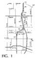
- FIG. 1is an illustrative example of a predefined route.
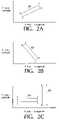
- FIGS. 2A–2Cdepict a process for ordering the coordinates that define each route rectangle.
- FIG. 3is a diagram illustrating the determination of the angle ⁇ of a route rectangle.
- FIG. 4is schematic diagram of a rotational transformation of a route rectangle.
- FIG. 5is a diagram illustrating the rotational transformation of a set of positional coordinates.
- FIG. 6is a diagram of a representative system for monitoring the position of a mobile unit.
- FIG. 7is a flow diagram of a process for monitoring a location of a vehicle.
- a geo-fencing routinecan be used to automatically initiate a predetermined response or action when a vehicle crosses a predefined virtual boundary.
- One implementationis in the context of having a fleet dispatch manager monitor vehicles. However, it should be understood that the routine can be used in other types of applications where it is desirable to monitor whether a vehicle, a mobile unit, or another monitored device has crossed one or more virtual boundaries.
- a fleet dispatch managercan restrict certain vehicles in a fleet from deviating from a predetermined route by defining a geo-fence or virtual boundary along the route.
- a predefined responsesuch as an alert sent to the dispatch manager's phone, PDA, desktop PC, or the like, can be automatically triggered.
- the fleet managercan then determine the cause of the deviation. If the fleet manager determines that the boundary has been crossed for an unauthorized, dangerous, or otherwise invalid reason, the fleet manager can remotely disable the vehicle, or take other appropriate action.
- the described techniqueshave a number of valuable applications. For example, they have vast implications with regard to homeland security in that they can be used to help prevent vehicles carrying hazardous, dangerous, or valuable cargo from being stolen. Similarly, they can prevent vehicles themselves from being stolen or used for unauthorized or illegal purposes.
- the techniquescan also enable a fleet operator to automate many costly and time consuming, yet time sensitive operations, such as advance warning prior to arrival at customer sites, depots, ports, load collection sites or any other desired location. Each unit in a fleet may be programmed or instructed to automatically notify the fleet controller or some other person or entity when leaving, or prior to reaching, specific locations.
- the described techniquesprovide an efficient way of defining a route and determining whether coordinates associated with a particular location lie within the defined route.
- the techniquesallow the majority of the calculations necessary for implementing a geo-fencing routine to be performed on a desktop computer or other high-powered processing device and require very little processing or communications by the monitored mobile device.
- FIGS. 2A–2Cillustrate a process for ordering the coordinates that define each route rectangle 105 . It will be understood that this process is primarily used for purposes of convenience and consistency in identifying rectangles 105 and that this process is not critical. In accordance with the illustrated numbering scheme, where the rectangle's sides are not parallel with the X- and Y-axis, corner 1 is the corner with the maximum Y value. In cases where the rectangle 105 has sides parallel to the X- and Y-axis, corner 1 is the corner of the rectangle 105 that has the maximum X value and the maximum Y value. In either case, the other corners are defined in a clockwise manner with respect to corner 1 .
- each rectangle 105is rotated about the origin by a corresponding angle ⁇ such that the sides of the rotated rectangle are parallel to the X-axis and the Y-axis.
- This rotational transformationcan be performed on a desktop computer so that the mobile or embedded device has less work to do when determining a position relative to the defined route.
- the rotated coordinates that define the rotated rectangle and the corresponding angle ⁇are loaded in a memory of the mobile or embedded device located on or in the vehicle to be monitored.
- the vehicle's positionis determined using, for example, a Global Positioning System (GPS) satellite receiver.
- GPSGlobal Positioning System
- the positional coordinatesare then rotated by the angle ⁇ associated with the particular rectangle, and the rotated positional coordinates are compared with the stored rotated coordinates for the particular rectangle.
- the mobile or embedded devicecan (1) do nothing, (2) send a predefined response to a central monitoring location, or (3) check the current location versus another rectangle in the overall route.
- each rectangle 105is first examined to determine whether it is situated with sides parallel to the X-axis and the Y-axis. If the sides are parallel to the axes, then no rotational transformation of the rectangle 105 is necessary. If, on the other hand, the rectangle's sides are not parallel to the X-axis and the Y-axis, the rectangle 105 is rotated so that the sides are parallel to the axes.
- the angle of rotationalso may be determined in other ways. For example, rectangle sides other than the one between corners 2 and 3 can be used.
- the rectangle 105might also be rotated in a counterclockwise direction by an angle ⁇ that equals 90 ⁇ .
- an arccosine or arctangent functionalso may be used.
- FIG. 4shows a rotational transformation of a rectangle 105 into a rectangle 105 ′ that is parallel to the X-axis and the Y-axis.
- the X and Y coordinates for each of points 1 and 3for example, can be plugged into the above equations to generate the coordinates for corners 1 and 3 of the rotated rectangle 105 ′.
- the routeis saved in XML format as a series of rotated rectangles 105 ′.
- the rectanglesare defined by the set of coordinates for each corner, and their corresponding angles of transformation ( ⁇ ).
- ⁇angles of transformation
- the mobile or embedded devicereads the XML file and stores each rectangle along with its corresponding angle of rotation ⁇ . While a particular route is active in the device, the position of the vehicle to be monitored is periodically determined by a GPS receiver. Alternatively, the position of the vehicle can be determined using another type of locating system, such as a system of terrestrial towers that transmit signals to and/or receive signals from a receiver/transmitter located in or on the vehicle. Such a system can use propagation times between the vehicle and the terrestrial towers to triangulate the vehicle's position. This type of triangulation system can be implemented, for example, using a cellular telecommunication infrastructure.
- the positional coordinates(e.g., GPS coordinates) are first rotated, if necessary, by the corresponding angle ⁇ . If the stored angle ⁇ is zero, then no rotation of the positional coordinates is performed. On the other hand, if the angle ⁇ is not equal to zero, the positional coordinates go through the same rotational transformation as the rectangle.
- the mobile or embedded devicethen checks to see if the positional coordinates are within the rotated rectangle 105 ′ by performing simple comparisons with the corners of the rotated rectangle 105 ′. If the vehicle is not within the current rectangle 105 , then the next and previous rectangles 105 are checked. If the vehicle is not in any of these rectangles 105 , then the vehicle has deviated from the predefined route.
- FIG. 5illustrates the rotational transformation of a set of positional coordinates.
- This transformationuses the same equations as the transformation of the route rectangles 105 performed on the desktop before the coordinates of the rotated rectangle 105 ′ are saved on the mobile or embedded device.
- the rotated positional coordinatesare then compared with the coordinates of the rotated rectangle 105 ′. If X′ ⁇ X 1 ′, X′ ⁇ X 3 ′, Y′ ⁇ Y 1 ′, and Y′ ⁇ Y 3 ′, then the vehicle is within the current rectangle 105 .
- FIG. 6illustrates a representative system for monitoring the position of a mobile unit 200 .
- the mobile unit 200represents the vehicle or other device for which a position is to be monitored.
- the mobile unit 200includes a GPS receiver 205 that can determine the current position of the mobile unit 200 based on signals received from GPS satellites 210 .
- the mobile unit 200also includes a processor 215 .
- the processor 215can be part of an embedded device (e.g., an onboard computer with limited functionality) or can be a general use processor that is part of the mobile unit 200 .
- a memory 220stores a route description that includes a series of rectangles 105 ′ that, prior to being loaded into the memory 220 , have been rotated to be parallel to the axes of the GPS coordinate system.
- the route descriptionincludes an angle of rotation corresponding to each rotated rectangle 105 ′.
- the route descriptioncan be loaded into the memory 220 through a wired or wireless interface.
- the route descriptionmay be loaded into the memory 220 from a mobile transceiver 225 that receives the route description over a radio interface 230 .
- the processor 215operates to periodically receive from the GPS receiver 205 a set of GPS coordinates that identify the mobile unit's current position. The processor 215 then transforms the received set of coordinates using one of the stored angles of rotation and compares the rotated coordinates to the corresponding rotated rectangle 105 ′ stored in the memory 220 , as described above.
- the processor 215determines that the mobile unit 200 has crossed a boundary defined by the route description, the processor 215 initiates a predetermined response. For example, the processor 215 may use the radio interface 230 to send a message from the mobile transceiver 225 to a central monitoring unit 235 .
- the messagecan be sent using any type of wireless communication infrastructure (not shown), such as a cellular telecommunication system, that then forwards the message to the central monitoring unit 235 .
- the central monitoring unit 235may include a server or other type of processor that takes some predetermined action in response to the received message, such as logging the event in a database or notifying a fleet dispatch manager through a desktop computer 240 or some other device (e.g., a pager) that includes a man-machine interface.
- the fleet dispatch managercan then take an appropriate action, such as disabling the monitored vehicle or contacting the driver to inquire about the nature of the deviation from the predefined route.
- the processor 215 of the mobile unit 200may simply log the deviation in a database stored in the memory 220 for later transfer to the central monitoring unit 235 .
- FIG. 7illustrates a process 300 for monitoring a location of a vehicle.
- the processbegins with defining a boundary in a coordinate system (step 305 ).
- the boundarymay be a series of overlapping rectangles 105 that define a route.
- each rectangle 105may represent a segment of the overall boundary.
- Each rectangle 105may be defined by two sets of coordinates that represent two opposite corners of the rectangle.
- the boundarymay be defined by one or more straight lines, each of which is defined by the coordinates of the line's end points and each of which represents a segment of the overall boundary.
- a boundary that includes one or more straight linesmay be used, for example, to help identify when a vehicle passes a pre-selected distance from a destination or an originating location.
- an angle ⁇is calculated for a first segment of the boundary (step 310 ).
- the angle ⁇is the angle between a straight edge of the segment and one of the axes of the coordinate system.
- the angle ⁇may be the angle between one side of a rectangle and the X-axis or the Y-axis, or the angle between a straight-line segment of the boundary and the X-axis or the Y-axis.
- Each boundary segmentis then rotated (step 315 ) by the angle ⁇ that corresponds to the segment, and the rotated coordinates and the angle ⁇ for the first segment are stored (step 320 ). For example, this information may be stored in a memory located in the vehicle or other mobile device to be monitored.
- a current location of the device to be monitoredis determined using, for example, a GPS receiver or other locating system (step 330 ). Steps are then taken to compare the current location with the boundary. In making this comparison, it is desirable to avoid checking the current location against every possible segment of the boundary. Thus, the comparison may begin with the first rectangle of a series of rectangles along a route. Once the device is found to have left the first rectangle, any adjacent rectangles may also be checked. As the monitored device proceeds along the route, the comparison may be performed on a current rectangle and, if the monitored device is found to have left the current rectangle, any adjacent rectangles.
- the coordinates of the current locationare rotated by the angle ⁇ associated with the current segment (step 335 ).
- the rotated coordinates of the current locationare then compared with the rotated coordinates of the selected segment (step 340 ). Based on this comparison, it is determined if the current location is within the boundary (i.e., based on whether the current location is within the selected segment) (step 345 ). If so, the current location is again determined after some delay period of variable or constant length (step 330 ).
- step 350the segment to be checked becomes the selected segment for use in steps 335 , 340 , and 345 . If an adjacent segment should not be checked, or if the maximum number of adjacent segments has already been checked, a predetermined response, such as notifying a fleet dispatch manager, is initiated (step 355 ).
Landscapes
- Physics & Mathematics (AREA)
- General Physics & Mathematics (AREA)
- Engineering & Computer Science (AREA)
- Theoretical Computer Science (AREA)
- Computer Networks & Wireless Communication (AREA)
- Signal Processing (AREA)
- Traffic Control Systems (AREA)
- Navigation (AREA)
- Position Fixing By Use Of Radio Waves (AREA)
- Selective Calling Equipment (AREA)
Abstract
Description
ΔY=Y2−Y3,
and the length of the side of the triangle adjacent the angle α is determined by:
ΔX=X2−X3.
Next, the length of the hypotenuse is calculated by:
h=√{square root over (ΔX2+ΔY2)}.
The angle α can then be determined by:
α=arcsin(ΔY/h)×(−1),
wherein the multiplication by −1 is used to produce a clockwise rotation. It will be recognized that the foregoing procedure for determining the angle α is illustrative only and that the angle of rotation also may be determined in other ways. For example, rectangle sides other than the one between
X′=Xcos(α)−Ysin(α)
Y′=Xsin(α)+Ycos(α)
Although it is possible to transform all four corners using these equations, it is generally sufficient to transform the two sets of coordinates representing opposite corners because these two sets of coordinates are sufficient to define the rotated
| <?xml version=“1.0”?> | ||
| <GEOFenceRoute> | ||
| <Coordinate Units=“DecimalDegrees”/> | ||
| <RECTANGLE> | ||
| <Longitude1>86.1700/Longitude1> | |
| <Latitude1>39.9925</Latitude1> | |
| <Longitude3>86.1555</Longitude3> | |
| <Latitude3>39.9805</Latitude3> | |
| <ALPHA Units=“RADIANS”>0.000000</ALPHA> |
| </RECTANGLE> | |
| <RECTANGLE> |
| <Longitude1>94.9208</Longitude1> | |
| <Latitude1>−2.7409</Latitude1> | |
| <Longitude3>94.9144</Longitude3> | |
| <Latitude3>−2.7448</Latitude3> | |
| <ALPHA Units=“RADIANS”>−0.463648</ALPHA> |
| </RECTANGLE> | |
| <RECTANGLE> |
| <Longitude1>91.0288</Longitude1> | |
| <Latitude1>−27.1332</Latitude1> | |
| <Longitude3>90.9882</Longitude3> | |
| <Latitude3>−27.1621</Latitude3> | |
| <ALPHA Units=“RADIANS”>−0.724866</ALPHA> |
| </RECTANGLE> | ||
| </GEOFenceRoute> | ||
In an alternative implementation, the coordinates may also be sent to the mobile or embedded device in a binary format to save space on the device.
X′=Xcos(α)−Ysin(α)
Y′=Xsin(α)+Ycos(α)
The rotated positional coordinates are then compared with the coordinates of the rotated
Claims (20)
Priority Applications (1)
| Application Number | Priority Date | Filing Date | Title |
|---|---|---|---|
| US10/822,490US6983202B2 (en) | 2002-11-22 | 2004-04-12 | Implementing geo-fencing on mobile devices |
Applications Claiming Priority (2)
| Application Number | Priority Date | Filing Date | Title |
|---|---|---|---|
| US10/301,994US6721652B1 (en) | 2002-11-22 | 2002-11-22 | Implementing geo-fencing on mobile devices |
| US10/822,490US6983202B2 (en) | 2002-11-22 | 2004-04-12 | Implementing geo-fencing on mobile devices |
Related Parent Applications (1)
| Application Number | Title | Priority Date | Filing Date |
|---|---|---|---|
| US10/301,994ContinuationUS6721652B1 (en) | 2002-11-22 | 2002-11-22 | Implementing geo-fencing on mobile devices |
Publications (2)
| Publication Number | Publication Date |
|---|---|
| US20040193368A1 US20040193368A1 (en) | 2004-09-30 |
| US6983202B2true US6983202B2 (en) | 2006-01-03 |
Family
ID=32043007
Family Applications (2)
| Application Number | Title | Priority Date | Filing Date |
|---|---|---|---|
| US10/301,994Expired - Fee RelatedUS6721652B1 (en) | 2002-11-22 | 2002-11-22 | Implementing geo-fencing on mobile devices |
| US10/822,490Expired - LifetimeUS6983202B2 (en) | 2002-11-22 | 2004-04-12 | Implementing geo-fencing on mobile devices |
Family Applications Before (1)
| Application Number | Title | Priority Date | Filing Date |
|---|---|---|---|
| US10/301,994Expired - Fee RelatedUS6721652B1 (en) | 2002-11-22 | 2002-11-22 | Implementing geo-fencing on mobile devices |
Country Status (9)
| Country | Link |
|---|---|
| US (2) | US6721652B1 (en) |
| EP (1) | EP1579404B1 (en) |
| AT (1) | ATE332555T1 (en) |
| AU (1) | AU2003294452B2 (en) |
| CA (1) | CA2505426C (en) |
| DE (1) | DE60306684T2 (en) |
| ES (1) | ES2268472T3 (en) |
| MX (1) | MXPA05005225A (en) |
| WO (1) | WO2004049282A1 (en) |
Cited By (33)
| Publication number | Priority date | Publication date | Assignee | Title |
|---|---|---|---|---|
| US20040138808A1 (en)* | 2002-11-22 | 2004-07-15 | Sanqunetti Douglas R. | Boundary detection algorithm for embedded devices |
| US20050159883A1 (en)* | 2004-01-16 | 2005-07-21 | Worldcom, Inc. | Method and system for tracked device location and route adherence via geofencing |
| US20070057818A1 (en)* | 2005-09-12 | 2007-03-15 | Rich Battista | System and method for reporting a status of an asset |
| US20070061072A1 (en)* | 2005-09-12 | 2007-03-15 | Markus Wuersch | System and method for the selection of a unique geographic feature |
| US20070057779A1 (en)* | 2005-09-12 | 2007-03-15 | Rich Battista | System and method for adaptive motion sensing with location determination |
| US20070288196A1 (en)* | 2003-11-20 | 2007-12-13 | Intelligent Spatial Technologies, Inc. | Mobile device and geographic information system background and summary of the related art |
| US20080109883A1 (en)* | 2006-04-25 | 2008-05-08 | Secure Network Systems, Llc | Logical and physical security |
| US20080162032A1 (en)* | 2006-06-30 | 2008-07-03 | Markus Wuersch | Mobile geographic information system and method |
| US20090015569A1 (en)* | 2007-07-10 | 2009-01-15 | Fuji Xerox Co., Ltd. | Image forming apparatus, information processing apparatus and display control method |
| US20090093958A1 (en)* | 2007-10-05 | 2009-04-09 | International Truck Intellectual Property Company, Llc | System and method for determining position within or without a complex polygon geofence |
| WO2010102176A1 (en)* | 2009-03-06 | 2010-09-10 | Vetrix, Llc | Systems and methods for mobile tracking, communications and alerting |
| US20100280852A1 (en)* | 2007-05-11 | 2010-11-04 | Palo Alto Research Center Incorporated | System And Method For Financial Transactions In A Rideshare Environment |
| US7834757B2 (en) | 2006-03-01 | 2010-11-16 | Trailer Dog, Llc | Method of mobile storage container protection |
| US20100306707A1 (en)* | 2008-12-22 | 2010-12-02 | David Caduff | System and Method for Exploring 3D Scenes by Pointing at a Reference Object |
| US20100303339A1 (en)* | 2008-12-22 | 2010-12-02 | David Caduff | System and Method for Initiating Actions and Providing Feedback by Pointing at Object of Interest |
| US20100306200A1 (en)* | 2008-12-22 | 2010-12-02 | Frank Christopher Edward | Mobile Image Search and Indexing System and Method |
| US20100303293A1 (en)* | 2008-12-22 | 2010-12-02 | David Caduff | System and Method for Linking Real-World Objects and Object Representations by Pointing |
| US20110102173A1 (en)* | 2009-10-30 | 2011-05-05 | Telenav, Inc. | Navigation system with context boundary monitoring mechanism and method of operation thereof |
| US20110106437A1 (en)* | 2009-10-30 | 2011-05-05 | Telenav, Inc. | Navigation system with monitoring mechanism and method of operation thereof |
| US20110124351A1 (en)* | 2003-11-20 | 2011-05-26 | Intelligent Spatial Technologies, Inc. | Mobile Device and Geographic Information System Background and Summary of the Related Art |
| US20110121964A1 (en)* | 2009-11-24 | 2011-05-26 | Bannard Kenneth R | Personnel tracking system |
| US20110178811A1 (en)* | 2010-01-19 | 2011-07-21 | Telenav, Inc. | Navigation system with geofence validation and method of operation thereof |
| US8078713B1 (en) | 2008-03-05 | 2011-12-13 | Full Armor Corporation | Delivering policy settings with virtualized applications |
| US20120001928A1 (en)* | 2005-03-07 | 2012-01-05 | Networks In Motion, Inc. | Method and system for identifying and defining geofences |
| US8209121B1 (en)* | 2007-10-10 | 2012-06-26 | Google Inc. | Registration of location data to street maps using hidden markov models, and application thereof |
| US9217651B2 (en) | 2003-02-14 | 2015-12-22 | Telecommunication Systems, Inc. | Method and system for saving and retrieving spatial related information |
| US9558468B2 (en) | 2011-03-16 | 2017-01-31 | Cubic Corporaton | Transportation route management |
| US9784583B2 (en) | 2005-09-12 | 2017-10-10 | Skybitz, Inc. | System and method for reporting a status of an asset |
| US9860256B2 (en) | 2015-11-02 | 2018-01-02 | Box, Inc. | Geofencing of data in a cloud-based environment |
| US9880186B2 (en) | 2014-09-29 | 2018-01-30 | Laird Technologies, Inc. | Telematics devices and methods for vehicle speeding detection |
| US10003919B2 (en) | 2014-12-11 | 2018-06-19 | Taiwan Semiconductor Manufacturing Co., Ltd. | Intelligent geo-fencing |
| US10536799B2 (en) | 2014-12-11 | 2020-01-14 | Taiwan Semiconductor Manufacturing Co., Ltd. | Intelligent geo-fencing with tracked and fenced objects |
| US10887267B2 (en) | 2018-09-12 | 2021-01-05 | International Business Machines Corporation | Intelligent notification routing and delivery |
Families Citing this family (111)
| Publication number | Priority date | Publication date | Assignee | Title |
|---|---|---|---|---|
| US7889133B2 (en) | 1999-03-05 | 2011-02-15 | Itt Manufacturing Enterprises, Inc. | Multilateration enhancements for noise and operations management |
| US7612716B2 (en) | 1999-03-05 | 2009-11-03 | Era Systems Corporation | Correlation of flight track data with other data sources |
| US7777675B2 (en) | 1999-03-05 | 2010-08-17 | Era Systems Corporation | Deployable passive broadband aircraft tracking |
| US7908077B2 (en) | 2003-06-10 | 2011-03-15 | Itt Manufacturing Enterprises, Inc. | Land use compatibility planning software |
| US7667647B2 (en) | 1999-03-05 | 2010-02-23 | Era Systems Corporation | Extension of aircraft tracking and positive identification from movement areas into non-movement areas |
| US7570214B2 (en) | 1999-03-05 | 2009-08-04 | Era Systems, Inc. | Method and apparatus for ADS-B validation, active and passive multilateration, and elliptical surviellance |
| US8203486B1 (en) | 1999-03-05 | 2012-06-19 | Omnipol A.S. | Transmitter independent techniques to extend the performance of passive coherent location |
| US7739167B2 (en) | 1999-03-05 | 2010-06-15 | Era Systems Corporation | Automated management of airport revenues |
| US8446321B2 (en) | 1999-03-05 | 2013-05-21 | Omnipol A.S. | Deployable intelligence and tracking system for homeland security and search and rescue |
| US7782256B2 (en) | 1999-03-05 | 2010-08-24 | Era Systems Corporation | Enhanced passive coherent location techniques to track and identify UAVs, UCAVs, MAVs, and other objects |
| US7333820B2 (en) | 2001-07-17 | 2008-02-19 | Networks In Motion, Inc. | System and method for providing routing, mapping, and relative position information to users of a communication network |
| BR0308165A (en) | 2002-03-01 | 2005-06-28 | Networks In Motion Inc | Method and apparatus for sending, retrieving and planning relevant location information |
| US8290505B2 (en) | 2006-08-29 | 2012-10-16 | Telecommunications Systems, Inc. | Consequential location derived information |
| US8918073B2 (en) | 2002-03-28 | 2014-12-23 | Telecommunication Systems, Inc. | Wireless telecommunications location based services scheme selection |
| US7565155B2 (en) | 2002-04-10 | 2009-07-21 | Networks In Motion | Method and system for dynamic estimation and predictive route generation |
| US6982656B1 (en)* | 2002-12-20 | 2006-01-03 | Innovative Processing Solutions, Llc | Asset monitoring and tracking system |
| AU2004302220A1 (en)* | 2003-08-08 | 2005-02-17 | Telecommunication Systems, Inc. | Method and system for collecting synchronizing and reporting telecommunication call events and work flow related information |
| US20080126535A1 (en) | 2006-11-28 | 2008-05-29 | Yinjun Zhu | User plane location services over session initiation protocol (SIP) |
| US20050258231A1 (en)* | 2004-05-18 | 2005-11-24 | Keith Wiater | Cruise ship passenger and baggage processing system |
| US7273172B2 (en) | 2004-07-14 | 2007-09-25 | United Parcel Service Of America, Inc. | Methods and systems for automating inventory and dispatch procedures at a staging area |
| US7395075B2 (en)* | 2004-09-09 | 2008-07-01 | Nextel Communications Inc. | System and method for collecting continuous location updates while minimizing overall network utilization |
| AU2005292243B2 (en)* | 2004-10-01 | 2011-03-10 | Telecommunication Systems, Inc. | Off board navigation solution |
| US8086519B2 (en)* | 2004-10-14 | 2011-12-27 | Cfph, Llc | System and method for facilitating a wireless financial transaction |
| US7323982B2 (en)* | 2004-11-05 | 2008-01-29 | Wirelesswerx International, Inc. | Method and system to control movable entities |
| US7860778B2 (en)* | 2004-11-08 | 2010-12-28 | Cfph, Llc | System and method for implementing push technology in a wireless financial transaction |
| US6990335B1 (en)* | 2004-11-18 | 2006-01-24 | Charles G. Shamoon | Ubiquitous connectivity and control system for remote locations |
| US7385499B2 (en)* | 2004-12-17 | 2008-06-10 | United Parcel Service Of America, Inc. | Item-based monitoring systems and methods |
| US20060176159A1 (en)* | 2005-01-28 | 2006-08-10 | Charles Chu | Wireless vehicle alarm system |
| US7466244B2 (en)* | 2005-04-21 | 2008-12-16 | Microsoft Corporation | Virtual earth rooftop overlay and bounding |
| US20060241859A1 (en) | 2005-04-21 | 2006-10-26 | Microsoft Corporation | Virtual earth real-time advertising |
| CN101228546A (en) | 2005-06-01 | 2008-07-23 | 茵诺苏伦斯公司 | Motor vehicle traveling data collection and analysis |
| CN1940480B (en)* | 2005-09-29 | 2010-11-10 | 上海乐金广电电子有限公司 | Hazardous area guiding method for location system |
| WO2008051236A2 (en)* | 2005-11-09 | 2008-05-02 | Sapias, Inc. | Geospatially aware vehicle security |
| BRPI0619558A2 (en)* | 2005-12-07 | 2011-10-04 | Networks In Motion Inc | portable electronic device and method for presenting information |
| US10878646B2 (en) | 2005-12-08 | 2020-12-29 | Smartdrive Systems, Inc. | Vehicle event recorder systems |
| US7941354B2 (en)* | 2005-12-16 | 2011-05-10 | Asset Intelligence, Llc | Method and system for lease of assets, such as trailers, storage devices and facilities |
| US7493211B2 (en)* | 2005-12-16 | 2009-02-17 | General Electric Company | System and method for updating geo-fencing information on mobile devices |
| WO2007073470A2 (en) | 2005-12-23 | 2007-06-28 | Perdiem, Llc | System and method for defining an event based on a relationship between an object location and a user-defined zone |
| US7525425B2 (en) | 2006-01-20 | 2009-04-28 | Perdiem Llc | System and method for defining an event based on relationship between an object location and a user-defined zone |
| US20070167175A1 (en)* | 2006-01-17 | 2007-07-19 | Tony Wong | Wireless virtual-network systems and methods to operate the same |
| US8996240B2 (en) | 2006-03-16 | 2015-03-31 | Smartdrive Systems, Inc. | Vehicle event recorders with integrated web server |
| US9201842B2 (en) | 2006-03-16 | 2015-12-01 | Smartdrive Systems, Inc. | Vehicle event recorder systems and networks having integrated cellular wireless communications systems |
| US8458661B2 (en) | 2006-03-31 | 2013-06-04 | Ebay Inc. | Distributed parallel build system |
| US8208605B2 (en) | 2006-05-04 | 2012-06-26 | Telecommunication Systems, Inc. | Extended efficient usage of emergency services keys |
| US7965227B2 (en) | 2006-05-08 | 2011-06-21 | Era Systems, Inc. | Aircraft tracking using low cost tagging as a discriminator |
| US10223891B2 (en)* | 2006-05-17 | 2019-03-05 | Peter Chlubek | Real-time multi-component web based travel safety system and method |
| US8649933B2 (en) | 2006-11-07 | 2014-02-11 | Smartdrive Systems Inc. | Power management systems for automotive video event recorders |
| US8989959B2 (en) | 2006-11-07 | 2015-03-24 | Smartdrive Systems, Inc. | Vehicle operator performance history recording, scoring and reporting systems |
| US8868288B2 (en) | 2006-11-09 | 2014-10-21 | Smartdrive Systems, Inc. | Vehicle exception event management systems |
| US20080125965A1 (en)* | 2006-11-27 | 2008-05-29 | Carani Sherry L | Tracking System and Method with Automatic Map Selector and Geo Fence Defining Features |
| US8239092B2 (en) | 2007-05-08 | 2012-08-07 | Smartdrive Systems Inc. | Distributed vehicle event recorder systems having a portable memory data transfer system |
| US20090055091A1 (en)* | 2007-08-24 | 2009-02-26 | Jeffery Scott Hines | Method, Apparatus, and Computer Program Product for Intelligently Selecting Between the Utilization of Geo-Fencing and Map Matching in a Telematics System |
| US8843312B2 (en)* | 2007-09-20 | 2014-09-23 | Omnitracs, Llc | Routing drivers to trailers effectively |
| US8099238B2 (en) | 2007-11-14 | 2012-01-17 | Telecommunication Systems, Inc. | Stateful, double-buffered dynamic navigation voice prompting |
| US11864051B2 (en)* | 2008-04-01 | 2024-01-02 | Blancco Technology Group IP Oy | Systems and methods for monitoring and managing use of mobile electronic devices |
| ES2330297B1 (en)* | 2008-06-05 | 2010-09-27 | Tinytronic, S.L. | METHOD, SYSTEM AND DEVICES OF RADIO-TRACKING. |
| US8145424B2 (en) | 2008-08-06 | 2012-03-27 | International Business Machines Corporation | Geoboundaries using rectangular fencing and coupling of GPS/LBS systems |
| JP4743305B2 (en)* | 2009-01-06 | 2011-08-10 | ソニー株式会社 | Function control method by boundary definition, function control system by boundary definition, function control server and program by boundary definition |
| US8653956B2 (en) | 2009-09-11 | 2014-02-18 | Hti Ip, L.L.C. | Method and system for implementing a geofence boundary for a tracked asset |
| US9715665B2 (en)* | 2009-09-21 | 2017-07-25 | Ford Global Technologies, Llc | Methods and systems for monitoring the condition of vehicle components from a nomadic wireless device or computer |
| US20110071725A1 (en)* | 2009-09-23 | 2011-03-24 | Ford Global Technologies, Llc | Remotely interacting with a vehicle to perform servicing and engineering functions from a nomadic device or computer |
| US8346432B2 (en)* | 2009-09-23 | 2013-01-01 | Ford Global Technologies, Llc | System and method for remotely controlling vehicle components from a nomadic communication device or computer |
| US8558690B2 (en)* | 2009-10-01 | 2013-10-15 | Ford Global Technologies, Llc | Vehicle system passive notification using remote device |
| US8525657B2 (en) | 2010-02-25 | 2013-09-03 | Ford Global Technologies, Llc | Methods and systems for determining a tire pressure status |
| US8558678B2 (en)* | 2010-02-25 | 2013-10-15 | Ford Global Technologies, Llc | Method and systems for detecting an unauthorized use of a vehicle by an authorized driver |
| US8614622B2 (en)* | 2010-03-08 | 2013-12-24 | Ford Global Technologies, Llc | Method and system for enabling an authorized vehicle driveaway |
| US10075806B2 (en)* | 2010-03-19 | 2018-09-11 | Ford Global Technologies, Llc | Wireless vehicle tracking |
| US20120254804A1 (en) | 2010-05-21 | 2012-10-04 | Sheha Michael A | Personal wireless navigation system |
| US8378815B1 (en) | 2010-10-28 | 2013-02-19 | Gemalto Sa | Asset tracking with error adaptive boundary |
| WO2012087353A1 (en) | 2010-12-22 | 2012-06-28 | Telecommunication Systems, Inc. | Area event handling when current network does not cover target area |
| US8682321B2 (en) | 2011-02-25 | 2014-03-25 | Telecommunication Systems, Inc. | Mobile internet protocol (IP) location |
| US8471701B2 (en)* | 2011-05-30 | 2013-06-25 | Microsoft Corporation | Asymmetric dynamic geo-fencing |
| US8700709B2 (en) | 2011-07-29 | 2014-04-15 | Microsoft Corporation | Conditional location-based reminders |
| WO2013048551A1 (en) | 2011-09-30 | 2013-04-04 | Telecommunication Systems, Inc. | Unique global identifier for minimizing prank 911 calls |
| US8996234B1 (en)* | 2011-10-11 | 2015-03-31 | Lytx, Inc. | Driver performance determination based on geolocation |
| US20130091197A1 (en) | 2011-10-11 | 2013-04-11 | Microsoft Corporation | Mobile device as a local server |
| US9298575B2 (en) | 2011-10-12 | 2016-03-29 | Lytx, Inc. | Drive event capturing based on geolocation |
| US8594921B2 (en) | 2011-11-30 | 2013-11-26 | At&T Mobility Ii Llc | Comparison of multi-dimensional datasets |
| EP2807454A4 (en) | 2012-01-26 | 2015-08-19 | Telecomm Systems Inc | Navigational lane guidance |
| US9544260B2 (en) | 2012-03-26 | 2017-01-10 | Telecommunication Systems, Inc. | Rapid assignment dynamic ownership queue |
| US9307372B2 (en) | 2012-03-26 | 2016-04-05 | Telecommunication Systems, Inc. | No responders online |
| US8930139B2 (en) | 2012-06-21 | 2015-01-06 | Telecommunication Systems, Inc. | Dynamically varied map labeling |
| US9728228B2 (en) | 2012-08-10 | 2017-08-08 | Smartdrive Systems, Inc. | Vehicle event playback apparatus and methods |
| WO2014028712A1 (en) | 2012-08-15 | 2014-02-20 | Telecommunication Systems, Inc. | Device independent caller data access for emergency calls |
| US20140094197A1 (en)* | 2012-10-03 | 2014-04-03 | Fisoc, Inc. | Speed and topology relevant dynamic geo search |
| US9805529B2 (en) | 2012-10-12 | 2017-10-31 | United Parcel Service Of America, Inc. | Concepts for asset identification |
| US9208538B2 (en) | 2012-11-07 | 2015-12-08 | Google Inc. | Rotated rectangle drawing on electronic devices |
| US9007398B1 (en) | 2012-11-12 | 2015-04-14 | Google Inc. | Rotated rectangle drawing |
| US9344683B1 (en) | 2012-11-28 | 2016-05-17 | Lytx, Inc. | Capturing driving risk based on vehicle state and automatic detection of a state of a location |
| US9456301B2 (en) | 2012-12-11 | 2016-09-27 | Telecommunication Systems, Inc. | Efficient prisoner tracking |
| US8983047B2 (en) | 2013-03-20 | 2015-03-17 | Telecommunication Systems, Inc. | Index of suspicion determination for communications request |
| WO2015024126A1 (en) | 2013-08-20 | 2015-02-26 | Intelligent Imaging Systems, Inc. | Vehicle traffic and vehicle related transaction control system |
| US9179257B2 (en) | 2013-08-21 | 2015-11-03 | Pitney Bowes Inc. | Method and system for determining high precision geo-fencing using business property boundaries |
| US9408034B2 (en) | 2013-09-09 | 2016-08-02 | Telecommunication Systems, Inc. | Extended area event for network based proximity discovery |
| US9516104B2 (en) | 2013-09-11 | 2016-12-06 | Telecommunication Systems, Inc. | Intelligent load balancer enhanced routing |
| US9479897B2 (en) | 2013-10-03 | 2016-10-25 | Telecommunication Systems, Inc. | SUPL-WiFi access point controller location based services for WiFi enabled mobile devices |
| US9501878B2 (en) | 2013-10-16 | 2016-11-22 | Smartdrive Systems, Inc. | Vehicle event playback apparatus and methods |
| US9610955B2 (en) | 2013-11-11 | 2017-04-04 | Smartdrive Systems, Inc. | Vehicle fuel consumption monitor and feedback systems |
| US8892310B1 (en) | 2014-02-21 | 2014-11-18 | Smartdrive Systems, Inc. | System and method to detect execution of driving maneuvers |
| US10099700B2 (en) | 2014-04-30 | 2018-10-16 | Ford Global Technologies, Llc | Method and system for driver tailored interaction time alert |
| US9663127B2 (en) | 2014-10-28 | 2017-05-30 | Smartdrive Systems, Inc. | Rail vehicle event detection and recording system |
| US11069257B2 (en) | 2014-11-13 | 2021-07-20 | Smartdrive Systems, Inc. | System and method for detecting a vehicle event and generating review criteria |
| US9972144B2 (en)* | 2015-03-24 | 2018-05-15 | At&T Intellectual Property I, L.P. | Automatic physical access |
| US9679420B2 (en) | 2015-04-01 | 2017-06-13 | Smartdrive Systems, Inc. | Vehicle event recording system and method |
| US9845097B2 (en) | 2015-08-12 | 2017-12-19 | Ford Global Technologies, Llc | Driver attention evaluation |
| US9788156B1 (en) | 2016-03-30 | 2017-10-10 | International Business Machines Corporation | Geofence determination |
| US10397734B2 (en) | 2016-11-11 | 2019-08-27 | International Business Machines Corporation | System and methodology for activating geofence from selection list |
| US9922531B1 (en)* | 2016-12-21 | 2018-03-20 | Tile, Inc. | Safe zones in tracking device environments |
| US10429200B1 (en)* | 2017-05-15 | 2019-10-01 | Uber Technologies, Inc. | Determining adjusted trip duration using route features |
| US11829410B2 (en) | 2019-07-02 | 2023-11-28 | International Business Machines Corporation | Playing user preferred music in a selected area |
| US11509642B2 (en)* | 2019-08-21 | 2022-11-22 | Truist Bank | Location-based mobile device authentication |
Citations (10)
| Publication number | Priority date | Publication date | Assignee | Title |
|---|---|---|---|---|
| US5270937A (en)* | 1991-04-26 | 1993-12-14 | Motorola, Inc. | Vehicle map position determining apparatus |
| JPH0814924A (en) | 1994-06-30 | 1996-01-19 | Matsushita Electric Ind Co Ltd | In-vehicle map display device |
| US5541845A (en)* | 1994-08-02 | 1996-07-30 | Trimble Navigation Limited | Monitoring of route and schedule adherence |
| US5724040A (en) | 1995-06-23 | 1998-03-03 | Northrop Grumman Corporation | Aircraft wake vortex hazard warning apparatus |
| US5801970A (en) | 1995-12-06 | 1998-09-01 | Martin Marietta Corporation | Model-based feature tracking system |
| US6185343B1 (en)* | 1997-01-17 | 2001-02-06 | Matsushita Electric Works, Ltd. | Position detection system and method |
| US20020072963A1 (en) | 1999-03-09 | 2002-06-13 | Jonge Wiebren De | Traffic information & pricing (TIP) system |
| US6581005B2 (en)* | 2000-11-30 | 2003-06-17 | Nissan Motor Co., Ltd. | Vehicle position calculation apparatus and method |
| US6728392B1 (en)* | 2001-01-30 | 2004-04-27 | Navigation Technologies Corp. | Shape comparison using a rotational variation metric and applications thereof |
| US20040102898A1 (en) | 2002-11-23 | 2004-05-27 | Tatsuo Yokota | Navigation method and system for indicating area-specific traffic information |
Family Cites Families (5)
| Publication number | Priority date | Publication date | Assignee | Title |
|---|---|---|---|---|
| JPS57144589A (en)* | 1981-03-04 | 1982-09-07 | Nissan Motor | Picture display unit |
| DE4402614A1 (en)* | 1994-01-28 | 1995-08-03 | Deutsche Telekom Mobil | Procedure for determining fees for the use of traffic routes by vehicles |
| DE19512074A1 (en)* | 1995-04-03 | 1996-10-10 | Ruediger Klaschka | Anti-theft device for a vehicle |
| US5694322A (en)* | 1995-05-09 | 1997-12-02 | Highwaymaster Communications, Inc. | Method and apparatus for determining tax of a vehicle |
| US5825283A (en)* | 1996-07-03 | 1998-10-20 | Camhi; Elie | System for the security and auditing of persons and property |
- 2002
- 2002-11-22USUS10/301,994patent/US6721652B1/ennot_activeExpired - Fee Related
- 2003
- 2003-11-21EPEP03789936Apatent/EP1579404B1/ennot_activeExpired - Lifetime
- 2003-11-21WOPCT/US2003/037370patent/WO2004049282A1/ennot_activeApplication Discontinuation
- 2003-11-21ESES03789936Tpatent/ES2268472T3/ennot_activeExpired - Lifetime
- 2003-11-21ATAT03789936Tpatent/ATE332555T1/ennot_activeIP Right Cessation
- 2003-11-21DEDE60306684Tpatent/DE60306684T2/ennot_activeExpired - Lifetime
- 2003-11-21MXMXPA05005225Apatent/MXPA05005225A/enactiveIP Right Grant
- 2003-11-21CACA 2505426patent/CA2505426C/ennot_activeExpired - Fee Related
- 2003-11-21AUAU2003294452Apatent/AU2003294452B2/ennot_activeCeased
- 2004
- 2004-04-12USUS10/822,490patent/US6983202B2/ennot_activeExpired - Lifetime
Patent Citations (10)
| Publication number | Priority date | Publication date | Assignee | Title |
|---|---|---|---|---|
| US5270937A (en)* | 1991-04-26 | 1993-12-14 | Motorola, Inc. | Vehicle map position determining apparatus |
| JPH0814924A (en) | 1994-06-30 | 1996-01-19 | Matsushita Electric Ind Co Ltd | In-vehicle map display device |
| US5541845A (en)* | 1994-08-02 | 1996-07-30 | Trimble Navigation Limited | Monitoring of route and schedule adherence |
| US5724040A (en) | 1995-06-23 | 1998-03-03 | Northrop Grumman Corporation | Aircraft wake vortex hazard warning apparatus |
| US5801970A (en) | 1995-12-06 | 1998-09-01 | Martin Marietta Corporation | Model-based feature tracking system |
| US6185343B1 (en)* | 1997-01-17 | 2001-02-06 | Matsushita Electric Works, Ltd. | Position detection system and method |
| US20020072963A1 (en) | 1999-03-09 | 2002-06-13 | Jonge Wiebren De | Traffic information & pricing (TIP) system |
| US6581005B2 (en)* | 2000-11-30 | 2003-06-17 | Nissan Motor Co., Ltd. | Vehicle position calculation apparatus and method |
| US6728392B1 (en)* | 2001-01-30 | 2004-04-27 | Navigation Technologies Corp. | Shape comparison using a rotational variation metric and applications thereof |
| US20040102898A1 (en) | 2002-11-23 | 2004-05-27 | Tatsuo Yokota | Navigation method and system for indicating area-specific traffic information |
Non-Patent Citations (1)
| Title |
|---|
| PCT International Search Report, PCT/US2004/036291, Mar. 6, 2005, pp. 1-4. |
Cited By (89)
| Publication number | Priority date | Publication date | Assignee | Title |
|---|---|---|---|---|
| US20040138808A1 (en)* | 2002-11-22 | 2004-07-15 | Sanqunetti Douglas R. | Boundary detection algorithm for embedded devices |
| US7680590B2 (en) | 2002-11-22 | 2010-03-16 | Hewlett-Packard Development Company, L.P. | Boundary detection algorithm for embedded devices |
| US9217651B2 (en) | 2003-02-14 | 2015-12-22 | Telecommunication Systems, Inc. | Method and system for saving and retrieving spatial related information |
| US8023962B2 (en) | 2003-11-20 | 2011-09-20 | Intelligent Spatial Technologies, Inc. | Mobile device and geographic information system background and summary of the related art |
| US8060112B2 (en) | 2003-11-20 | 2011-11-15 | Intellient Spatial Technologies, Inc. | Mobile device and geographic information system background and summary of the related art |
| US20070288196A1 (en)* | 2003-11-20 | 2007-12-13 | Intelligent Spatial Technologies, Inc. | Mobile device and geographic information system background and summary of the related art |
| US20110124351A1 (en)* | 2003-11-20 | 2011-05-26 | Intelligent Spatial Technologies, Inc. | Mobile Device and Geographic Information System Background and Summary of the Related Art |
| US9237420B2 (en) | 2003-11-20 | 2016-01-12 | Intel Corporation | Mobile device and geographic information system background and summary of the related art |
| US8929911B2 (en) | 2003-11-20 | 2015-01-06 | Ipointer Inc. | Mobile device and geographic information system background and summary of the related art |
| US9913098B2 (en) | 2003-11-20 | 2018-03-06 | Intel Corporation | Mobile device and geographic information system background and summary of the related art |
| US20050159883A1 (en)* | 2004-01-16 | 2005-07-21 | Worldcom, Inc. | Method and system for tracked device location and route adherence via geofencing |
| US7164986B2 (en)* | 2004-01-16 | 2007-01-16 | Mci, Llc | Method and system for tracked device location and route adherence via geofencing |
| US8731813B2 (en)* | 2005-03-07 | 2014-05-20 | Telecommunication Systems, Inc. | Method and system for identifying and defining geofences |
| US20150365799A1 (en)* | 2005-03-07 | 2015-12-17 | Telecommunication Systems, Inc. | Method and System for Identifying and Defining Geofences |
| US9137636B2 (en)* | 2005-03-07 | 2015-09-15 | Telecommunication Systems, Inc. | Method and system for identifying and defining geofences |
| US20140292511A1 (en)* | 2005-03-07 | 2014-10-02 | Telecommunication Systems, Inc. | Method and System for Identifying and Defining Geofences |
| US9503850B2 (en)* | 2005-03-07 | 2016-11-22 | Telecommunication Systems, Inc. | Method and system for identifying and defining geofences |
| US20120001928A1 (en)* | 2005-03-07 | 2012-01-05 | Networks In Motion, Inc. | Method and system for identifying and defining geofences |
| US20080262723A1 (en)* | 2005-09-12 | 2008-10-23 | Intelligent Spatial Technologies, Inc. | System and method for the selection of a unique geographic feature |
| US9064421B2 (en) | 2005-09-12 | 2015-06-23 | Skybitz, Inc. | System and method for reporting a status of an asset |
| US20070057818A1 (en)* | 2005-09-12 | 2007-03-15 | Rich Battista | System and method for reporting a status of an asset |
| US9704399B2 (en) | 2005-09-12 | 2017-07-11 | Skybitz, Inc. | System and method for adaptive motion sensing with location determination |
| US20070061072A1 (en)* | 2005-09-12 | 2007-03-15 | Markus Wuersch | System and method for the selection of a unique geographic feature |
| US20090135027A1 (en)* | 2005-09-12 | 2009-05-28 | Rich Battista | System and method for reporting a status of an asset |
| US9784583B2 (en) | 2005-09-12 | 2017-10-10 | Skybitz, Inc. | System and method for reporting a status of an asset |
| US7498925B2 (en) | 2005-09-12 | 2009-03-03 | Skybitz, Inc. | System and method for reporting a status of an asset |
| US7486174B2 (en) | 2005-09-12 | 2009-02-03 | Skybitz, Inc. | System and method for adaptive motion sensing with location determination |
| US9128179B2 (en) | 2005-09-12 | 2015-09-08 | Skybitz, Inc. | System and method for adaptive motion sensing with location determination |
| US20110010044A1 (en)* | 2005-09-12 | 2011-01-13 | Rich Battista | System and Method for Reporting a Status of an Asset |
| US7804394B2 (en) | 2005-09-12 | 2010-09-28 | Skybitz, Inc. | System and method for reporting a status of an asset |
| US20110224943A1 (en)* | 2005-09-12 | 2011-09-15 | Rich Battista | System and Method for Adaptive Motion Sensing with Location Determination |
| US7911329B2 (en) | 2005-09-12 | 2011-03-22 | Skybitz, Inc. | System and method for adaptive motion sensing with location determination |
| US7418341B2 (en)* | 2005-09-12 | 2008-08-26 | Intelligent Spatial Technologies | System and method for the selection of a unique geographic feature |
| US20070057779A1 (en)* | 2005-09-12 | 2007-03-15 | Rich Battista | System and method for adaptive motion sensing with location determination |
| US8560225B2 (en)* | 2005-09-12 | 2013-10-15 | IPointer, Inc. | System and method for the selection of a unique geographic feature |
| US7834757B2 (en) | 2006-03-01 | 2010-11-16 | Trailer Dog, Llc | Method of mobile storage container protection |
| US20080109883A1 (en)* | 2006-04-25 | 2008-05-08 | Secure Network Systems, Llc | Logical and physical security |
| US8108914B2 (en) | 2006-04-25 | 2012-01-31 | Vetrix, Llc | Converged logical and physical security |
| US9400881B2 (en) | 2006-04-25 | 2016-07-26 | Vetrix, Llc | Converged logical and physical security |
| US8538676B2 (en) | 2006-06-30 | 2013-09-17 | IPointer, Inc. | Mobile geographic information system and method |
| US20080162032A1 (en)* | 2006-06-30 | 2008-07-03 | Markus Wuersch | Mobile geographic information system and method |
| US20100280752A1 (en)* | 2007-05-11 | 2010-11-04 | Palo Alto Research Center Incorporated | System and method for monitoring participant security in a rideshare environment |
| US20100280854A1 (en)* | 2007-05-11 | 2010-11-04 | Palo Alto Research Center Incorporated | System And Method For Matching Participants In A Rideshare Program |
| US20110196709A1 (en)* | 2007-05-11 | 2011-08-11 | Palo Alto Research Center Incorporated | System And Method For Setting A Rideshare Transaction Fee |
| US20100280852A1 (en)* | 2007-05-11 | 2010-11-04 | Palo Alto Research Center Incorporated | System And Method For Financial Transactions In A Rideshare Environment |
| US8036824B2 (en) | 2007-05-11 | 2011-10-11 | Palo Alto Research Center Incorporated | System and method for setting a rideshare transaction fee |
| US20110196708A1 (en)* | 2007-05-11 | 2011-08-11 | Palo Alto Research Center Incorporated | System And Method For Financing A Rideshare System |
| US7974779B2 (en) | 2007-05-11 | 2011-07-05 | Palo Alto Research Center Incorporated | System and method for assigning participants to a rideshare based on financial transactions |
| US7869945B2 (en) | 2007-05-11 | 2011-01-11 | Palo Alto Research Center Incorporated | System and method for monitoring participant security in a rideshare environment |
| US8086400B2 (en) | 2007-05-11 | 2011-12-27 | Palo Alto Research Center Incorporated | System and method for monitoring the security of participants in a rideshare environment |
| US7970533B2 (en) | 2007-05-11 | 2011-06-28 | Palo Alto Research Center Incorporated | System and method for matching participants in a rideshare program |
| US8095305B2 (en) | 2007-05-11 | 2012-01-10 | Palo Alto Research Center Incorporated | System and method for financing a rideshare system |
| US20110018719A1 (en)* | 2007-05-11 | 2011-01-27 | Palo Alto Research Center Incorporated | System And Method For Rideshare Security |
| US20110022491A1 (en)* | 2007-05-11 | 2011-01-27 | Palo Alto Research Center Incorporated | System And Method For Assigning Participants To A Rideshare Based On Financial Transactions |
| US7930098B2 (en) | 2007-05-11 | 2011-04-19 | Palo Alto Research Center Incorporated | System and method for financial transactions in a rideshare environment |
| US8224571B2 (en) | 2007-05-11 | 2012-07-17 | Palo Alto Research Center Incorporated | System and method for rideshare security |
| US20110093193A1 (en)* | 2007-05-11 | 2011-04-21 | Palo Alto Research Center Incorporated | System And Method For Monitoring The Security Of Participants In A Rideshare Environment |
| US20090015569A1 (en)* | 2007-07-10 | 2009-01-15 | Fuji Xerox Co., Ltd. | Image forming apparatus, information processing apparatus and display control method |
| US20090093958A1 (en)* | 2007-10-05 | 2009-04-09 | International Truck Intellectual Property Company, Llc | System and method for determining position within or without a complex polygon geofence |
| US8046168B2 (en)* | 2007-10-05 | 2011-10-25 | International Truck Intellectual Property Company, Llc | System and method for determining position within or without a complex polygon geofence |
| US8209121B1 (en)* | 2007-10-10 | 2012-06-26 | Google Inc. | Registration of location data to street maps using hidden markov models, and application thereof |
| US8078713B1 (en) | 2008-03-05 | 2011-12-13 | Full Armor Corporation | Delivering policy settings with virtualized applications |
| US20100303339A1 (en)* | 2008-12-22 | 2010-12-02 | David Caduff | System and Method for Initiating Actions and Providing Feedback by Pointing at Object of Interest |
| US20100306200A1 (en)* | 2008-12-22 | 2010-12-02 | Frank Christopher Edward | Mobile Image Search and Indexing System and Method |
| US8483519B2 (en) | 2008-12-22 | 2013-07-09 | Ipointer Inc. | Mobile image search and indexing system and method |
| US8745090B2 (en) | 2008-12-22 | 2014-06-03 | IPointer, Inc. | System and method for exploring 3D scenes by pointing at a reference object |
| US8494255B2 (en) | 2008-12-22 | 2013-07-23 | IPointer, Inc. | System and method for linking real-world objects and object representations by pointing |
| US8873857B2 (en) | 2008-12-22 | 2014-10-28 | Ipointer Inc. | Mobile image search and indexing system and method |
| US8184858B2 (en) | 2008-12-22 | 2012-05-22 | Intelligent Spatial Technologies Inc. | System and method for linking real-world objects and object representations by pointing |
| US8675912B2 (en) | 2008-12-22 | 2014-03-18 | IPointer, Inc. | System and method for initiating actions and providing feedback by pointing at object of interest |
| US20100306707A1 (en)* | 2008-12-22 | 2010-12-02 | David Caduff | System and Method for Exploring 3D Scenes by Pointing at a Reference Object |
| US20100303293A1 (en)* | 2008-12-22 | 2010-12-02 | David Caduff | System and Method for Linking Real-World Objects and Object Representations by Pointing |
| WO2010102176A1 (en)* | 2009-03-06 | 2010-09-10 | Vetrix, Llc | Systems and methods for mobile tracking, communications and alerting |
| US11438732B2 (en) | 2009-03-06 | 2022-09-06 | Vetrix, Llc | Systems and methods for mobile tracking, communications and alerting |
| US20110106437A1 (en)* | 2009-10-30 | 2011-05-05 | Telenav, Inc. | Navigation system with monitoring mechanism and method of operation thereof |
| US20110102173A1 (en)* | 2009-10-30 | 2011-05-05 | Telenav, Inc. | Navigation system with context boundary monitoring mechanism and method of operation thereof |
| US8433508B2 (en) | 2009-10-30 | 2013-04-30 | Televav, Inc. | Navigation system with monitoring mechanism and method of operation thereof |
| US8232877B2 (en) | 2009-10-30 | 2012-07-31 | Telenav, Inc. | Navigation system with context boundary monitoring mechanism and method of operation thereof |
| US20110121964A1 (en)* | 2009-11-24 | 2011-05-26 | Bannard Kenneth R | Personnel tracking system |
| US8378813B2 (en) | 2009-11-24 | 2013-02-19 | Kenneth R. Bannard | Personnel tracking system |
| US20110178811A1 (en)* | 2010-01-19 | 2011-07-21 | Telenav, Inc. | Navigation system with geofence validation and method of operation thereof |
| US9558468B2 (en) | 2011-03-16 | 2017-01-31 | Cubic Corporaton | Transportation route management |
| US9880186B2 (en) | 2014-09-29 | 2018-01-30 | Laird Technologies, Inc. | Telematics devices and methods for vehicle speeding detection |
| US9934622B2 (en) | 2014-09-29 | 2018-04-03 | Laird Technologies, Inc. | Telematics devices and methods for vehicle ignition detection |
| US10003919B2 (en) | 2014-12-11 | 2018-06-19 | Taiwan Semiconductor Manufacturing Co., Ltd. | Intelligent geo-fencing |
| US10536799B2 (en) | 2014-12-11 | 2020-01-14 | Taiwan Semiconductor Manufacturing Co., Ltd. | Intelligent geo-fencing with tracked and fenced objects |
| US9860256B2 (en) | 2015-11-02 | 2018-01-02 | Box, Inc. | Geofencing of data in a cloud-based environment |
| US10454944B2 (en) | 2015-11-02 | 2019-10-22 | Box, Inc. | Geofencing of data in a cloud-based environment |
| US10887267B2 (en) | 2018-09-12 | 2021-01-05 | International Business Machines Corporation | Intelligent notification routing and delivery |
Also Published As
| Publication number | Publication date |
|---|---|
| AU2003294452A1 (en) | 2004-06-18 |
| US20040193368A1 (en) | 2004-09-30 |
| DE60306684D1 (en) | 2006-08-17 |
| CA2505426C (en) | 2008-08-05 |
| WO2004049282A1 (en) | 2004-06-10 |
| CA2505426A1 (en) | 2004-06-10 |
| ES2268472T3 (en) | 2007-03-16 |
| ATE332555T1 (en) | 2006-07-15 |
| EP1579404A1 (en) | 2005-09-28 |
| EP1579404B1 (en) | 2006-07-05 |
| DE60306684T2 (en) | 2007-06-28 |
| AU2003294452B2 (en) | 2008-10-02 |
| MXPA05005225A (en) | 2005-07-25 |
| US6721652B1 (en) | 2004-04-13 |
Similar Documents
| Publication | Publication Date | Title |
|---|---|---|
| US6983202B2 (en) | Implementing geo-fencing on mobile devices | |
| US11526834B2 (en) | Tracking system and method for monitoring and ensuring security of shipments | |
| US11455870B2 (en) | Automated monitoring, detection, and reporting of unauthorized movement and/or theft of vehicles and cargo | |
| US6457129B2 (en) | Geographic location receiver based computer system security | |
| EP2589232B1 (en) | Automatic creation and modification of dynamic geofences | |
| US8018329B2 (en) | Automated geo-fence boundary configuration and activation | |
| US6327533B1 (en) | Method and apparatus for continuously locating an object | |
| US20180211543A1 (en) | Method, apparatus and system for monitoring vehicle driving safety | |
| US20090243925A1 (en) | Infrastructure and method for geography based vehicle alert | |
| KR20040063077A (en) | Method and apparatus for locating mobile units tracking another | |
| US12112341B1 (en) | Asset tracker loss alert and notification process | |
| EP3662426B1 (en) | Tracking system and method for monitoring and ensuring security of shipments | |
| US10764716B2 (en) | Method and system for monitoring the position of an object | |
| JP2000092567A (en) | Terminal device authentication device | |
| JP2001343446A (en) | Location information monitor system and providing method | |
| Usman et al. | A Model for Smart Vehicle Tracking: A Review | |
| NC et al. | Microcontroller-Based Vehicle Tracking System Using GPS and GSM Module: A Mini Review. | |
| Nadu et al. | Anti-theft vehicle tracking with automatic police notifying using haversine formula | |
| WO2022130399A1 (en) | A system for tracking and locating a stolen vehicle and a method therefor | |
| JP2007503792A (en) | Two-way SMS / XML position search API |
Legal Events
| Date | Code | Title | Description |
|---|---|---|---|
| AS | Assignment | Owner name:ELECTRONIC DATA SYSTEMS CORPORATION, TEXAS Free format text:ASSIGNMENT OF ASSIGNORS INTEREST;ASSIGNOR:SANQUNETTI, DOUGLAS R.;REEL/FRAME:016033/0358 Effective date:20021210 | |
| STCF | Information on status: patent grant | Free format text:PATENTED CASE | |
| AS | Assignment | Owner name:ELECTRONIC DATA SYSTEMS, LLC, DELAWARE Free format text:CHANGE OF NAME;ASSIGNOR:ELECTRONIC DATA SYSTEMS CORPORATION;REEL/FRAME:022460/0948 Effective date:20080829 Owner name:ELECTRONIC DATA SYSTEMS, LLC,DELAWARE Free format text:CHANGE OF NAME;ASSIGNOR:ELECTRONIC DATA SYSTEMS CORPORATION;REEL/FRAME:022460/0948 Effective date:20080829 | |
| AS | Assignment | Owner name:HEWLETT-PACKARD DEVELOPMENT COMPANY, L.P., TEXAS Free format text:ASSIGNMENT OF ASSIGNORS INTEREST;ASSIGNOR:ELECTRONIC DATA SYSTEMS, LLC;REEL/FRAME:022449/0267 Effective date:20090319 Owner name:HEWLETT-PACKARD DEVELOPMENT COMPANY, L.P.,TEXAS Free format text:ASSIGNMENT OF ASSIGNORS INTEREST;ASSIGNOR:ELECTRONIC DATA SYSTEMS, LLC;REEL/FRAME:022449/0267 Effective date:20090319 | |
| FPAY | Fee payment | Year of fee payment:4 | |
| FEPP | Fee payment procedure | Free format text:PAYOR NUMBER ASSIGNED (ORIGINAL EVENT CODE: ASPN); ENTITY STATUS OF PATENT OWNER: LARGE ENTITY | |
| FPAY | Fee payment | Year of fee payment:8 | |
| AS | Assignment | Owner name:HEWLETT PACKARD ENTERPRISE DEVELOPMENT LP, TEXAS Free format text:ASSIGNMENT OF ASSIGNORS INTEREST;ASSIGNOR:HEWLETT-PACKARD DEVELOPMENT COMPANY, L.P.;REEL/FRAME:037079/0001 Effective date:20151027 | |
| FPAY | Fee payment | Year of fee payment:12 | |
| AS | Assignment | Owner name:OT PATENT ESCROW, LLC, ILLINOIS Free format text:PATENT ASSIGNMENT, SECURITY INTEREST, AND LIEN AGREEMENT;ASSIGNORS:HEWLETT PACKARD ENTERPRISE DEVELOPMENT LP;HEWLETT PACKARD ENTERPRISE COMPANY;REEL/FRAME:055269/0001 Effective date:20210115 | |
| AS | Assignment | Owner name:VALTRUS INNOVATIONS LIMITED, IRELAND Free format text:ASSIGNMENT OF ASSIGNORS INTEREST;ASSIGNOR:OT PATENT ESCROW, LLC;REEL/FRAME:055403/0001 Effective date:20210201 |