US6983169B2 - Wireless device allowing for configuration of settings and method therefor - Google Patents
Wireless device allowing for configuration of settings and method thereforDownload PDFInfo
- Publication number
- US6983169B2 US6983169B2US10/388,774US38877403AUS6983169B2US 6983169 B2US6983169 B2US 6983169B2US 38877403 AUS38877403 AUS 38877403AUS 6983169 B2US6983169 B2US 6983169B2
- Authority
- US
- United States
- Prior art keywords
- wireless device
- detecting
- input pad
- call
- holster
- Prior art date
- Legal status (The legal status is an assumption and is not a legal conclusion. Google has not performed a legal analysis and makes no representation as to the accuracy of the status listed.)
- Expired - Lifetime, expires
Links
- 238000000034methodMethods0.000titleclaimsabstractdescription26
- 230000009471actionEffects0.000claimsabstractdescription7
- 230000004044responseEffects0.000claimsabstractdescription7
- 239000004065semiconductorSubstances0.000claimsdescription16
- 230000003287optical effectEffects0.000claimsdescription10
- 230000000977initiatory effectEffects0.000claimsdescription5
- 235000014676Phragmites communisNutrition0.000claimsdescription4
- 238000004891communicationMethods0.000description35
- 238000010586diagramMethods0.000description20
- 238000004590computer programMethods0.000description14
- 230000006870functionEffects0.000description14
- 230000005355Hall effectEffects0.000description11
- 230000009286beneficial effectEffects0.000description10
- 230000008569processEffects0.000description10
- 230000001413cellular effectEffects0.000description5
- 239000000463materialSubstances0.000description3
- 230000005540biological transmissionEffects0.000description2
- 239000000872bufferSubstances0.000description2
- 230000008859changeEffects0.000description2
- 239000002800charge carrierSubstances0.000description2
- 230000008878couplingEffects0.000description2
- 238000010168coupling processMethods0.000description2
- 238000005859coupling reactionMethods0.000description2
- 230000004907fluxEffects0.000description2
- 230000010365information processingEffects0.000description2
- 238000005259measurementMethods0.000description2
- CWYNVVGOOAEACU-UHFFFAOYSA-NFe2+Chemical compound[Fe+2]CWYNVVGOOAEACU-UHFFFAOYSA-N0.000description1
- 238000006243chemical reactionMethods0.000description1
- 238000013500data storageMethods0.000description1
- 238000001514detection methodMethods0.000description1
- 238000011161developmentMethods0.000description1
- 210000005069earsAnatomy0.000description1
- 230000001747exhibiting effectEffects0.000description1
- 239000000835fiberSubstances0.000description1
- 238000012423maintenanceMethods0.000description1
- 238000007726management methodMethods0.000description1
- 239000002184metalSubstances0.000description1
- 238000010295mobile communicationMethods0.000description1
- 238000012986modificationMethods0.000description1
- 230000004048modificationEffects0.000description1
- 238000012544monitoring processMethods0.000description1
Images


Classifications
- H—ELECTRICITY
- H04—ELECTRIC COMMUNICATION TECHNIQUE
- H04M—TELEPHONIC COMMUNICATION
- H04M1/00—Substation equipment, e.g. for use by subscribers
- H04M1/72—Mobile telephones; Cordless telephones, i.e. devices for establishing wireless links to base stations without route selection
- H04M1/724—User interfaces specially adapted for cordless or mobile telephones
- H04M1/72448—User interfaces specially adapted for cordless or mobile telephones with means for adapting the functionality of the device according to specific conditions
- H04M1/72454—User interfaces specially adapted for cordless or mobile telephones with means for adapting the functionality of the device according to specific conditions according to context-related or environment-related conditions
- H—ELECTRICITY
- H04—ELECTRIC COMMUNICATION TECHNIQUE
- H04B—TRANSMISSION
- H04B1/00—Details of transmission systems, not covered by a single one of groups H04B3/00 - H04B13/00; Details of transmission systems not characterised by the medium used for transmission
- H04B1/38—Transceivers, i.e. devices in which transmitter and receiver form a structural unit and in which at least one part is used for functions of transmitting and receiving
- H04B1/40—Circuits
- H—ELECTRICITY
- H04—ELECTRIC COMMUNICATION TECHNIQUE
- H04M—TELEPHONIC COMMUNICATION
- H04M1/00—Substation equipment, e.g. for use by subscribers
- H04M1/72—Mobile telephones; Cordless telephones, i.e. devices for establishing wireless links to base stations without route selection
- H04M1/724—User interfaces specially adapted for cordless or mobile telephones
- H04M1/72448—User interfaces specially adapted for cordless or mobile telephones with means for adapting the functionality of the device according to specific conditions
- H—ELECTRICITY
- H04—ELECTRIC COMMUNICATION TECHNIQUE
- H04M—TELEPHONIC COMMUNICATION
- H04M2250/00—Details of telephonic subscriber devices
- H04M2250/12—Details of telephonic subscriber devices including a sensor for measuring a physical value, e.g. temperature or motion
Definitions
- the present inventiongenerally relates to the field of wireless communication systems, and more particularly relates to the configuration of settings on a wireless device.
- the system on a wireless deviceincludes means for detecting a user action indicating a particular mode for the wireless device.
- the means for detectingincludes any one of means for detecting the proximity of a holster for holding the wireless device and means for detecting an on-call status and/or an off-call status of the wireless device.
- the system on a wireless devicefurther includes a processor in the wireless device for configuring settings of the wireless device in response to the user action.
- the configuring of settingsis performed any one of manually and automatically.
- the settings of the wireless deviceinclude at least one of a ring setting, a battery setting, an input pad setting and a device use setting.
- the system on a wireless deviceincludes means for detecting the proximity of a holster for holding the wireless device, wherein if the holster is detected within a proximity threshold, a signal is generated.
- the wireless devicefurther includes a processor in the wireless device for receiving the signal and for configuring settings of the wireless device.
- the means for detecting the proximity of the holsterincludes any one of a semiconductor, a reed switch, a circular conducting element, a switch and optical means.
- the settings of the wireless deviceinclude at least one of a ring setting, a battery setting, an input pad setting and a device use setting.
- the configuration of the ring settingis beneficial when the wireless device is in the holster because it allows a user to avoid loud and/or disruptive ringing.
- the wireless deviceis in the holster, there is no need for the device to ring due to the proximity of the wireless device 106 to the user.
- the vibration of the wireless device 106notifies the user of an incoming call.
- the configuration of the ring settingis also advantageous because it eliminates the repeated adjustment of the ring setting by a user when he enters into situation when a ring is not appropriate, such as in a movie theater or a place of worship.
- the configuration of the ring settingis further advantageous because it reduces the number of missed calls due to the removal of a wireless device from a user's person when the wireless device is set to vibrate. Users often miss calls when the wireless device is not attached to the user and it is set to vibrate.
- a preferred embodiment according to the present inventionconfigures the wireless device to ring when it is removed from the holster, thereby allowing the user to hear the wireless device when it receives an incoming call.
- the configuration of the battery settingis beneficial when the wireless device is in the holster because it saves battery life and allows for longer use of the wireless device between charges.
- the present inventionconfigures the battery setting of the wireless device to battery save mode when it is inserted into the holster, thereby saving battery life.
- the configuration of the input pad settingis beneficial when the wireless device is in the holster because it eliminates the accidental entry of information via the input pad when the wireless device is not in use.
- the present inventionconfigures the input pad setting of the wireless device to be disabled when it is inserted into the holster, thereby preventing accidental entry of information.
- the configuration of the device use settingis beneficial when the wireless device has been removed from the holster for a set period of time because it prevents the unauthorized use of the wireless device by others.
- the present inventionconfigures the device use setting of the wireless device to be disabled. This security feature prevents the unauthorized use of the wireless device when it has been removed from the holster and is not in the possession of the user.
- the configuration of the input pad settingis beneficial when the wireless device is in use because it eliminates the accidental entry of information via the input pad when a user is speaking into the wireless device 106 .
- the present inventionconfigures the input pad setting of the wireless device to be disabled when it is in use, thereby preventing accidental entry of information.
- FIG. 1is a block diagram illustrating a conventional wireless communication system.
- FIG. 2is a more detailed block diagram of a conventional wireless communication system.
- FIG. 3is a block diagram illustrating a conventional wireless device for a wireless communication system.
- FIG. 4is an illustration of a front side view of an exemplary wireless device.
- FIG. 5is an illustration of a back side view of an exemplary wireless device.
- FIG. 6is an illustration of a side view of an exemplary wireless device.
- FIG. 7is an illustration of a front side view of a holster.
- FIG. 8is an illustration of a side view of a holster.
- FIG. 9is an illustration of a side view of an exemplary wireless device coupled with a holster.
- FIG. 10is an illustration of a semiconductor for use in a Hall effect sensor.
- FIG. 11is an operational flow diagram showing a configuration setting process of a wireless device according to a preferred embodiment of the present invention.
- FIG. 12is an operational flow diagram showing another configuration setting process of a wireless device according to a preferred embodiment of the present invention.
- FIG. 13is a block diagram of an information processing system useful for implementing a preferred embodiment of the present invention.
- the terms “a” or “an”, as used herein,are defined as one or more than one.
- the term plurality, as used herein,is defined as two or more than two.
- the term another, as used herein,is defined as at least a second or more.
- the terms including and/or having, as used herein,are defined as comprising (i.e., open language).
- the term coupled, as used herein,is defined as connected, although not necessarily directly, and not necessarily mechanically.
- program, software application, and the like as used herein,are defined as a sequence of instructions designed for execution on a computer system.
- a program, computer program, or software applicationmay include a subroutine, a function, a procedure, an object method, an object implementation, an executable application, an applet, a servlet, a source code, an object code, a shared library/dynamic load library and/or other sequence of instructions designed for execution on a computer system.
- the present inventionadvantageously overcomes problems with the prior art by providing a system, method and computer program product for adjusting configuration settings of a wireless device, as will be discussed in detail below.
- FIG. 1is a block diagram illustrating a conventional wireless communication system.
- FIG. 1shows a wireless service provider 102 operating on a wireless network 104 , which connects the wireless service provider 102 with wireless devices 106 and 108 .
- the wireless service provider 102is a first-generation analog mobile phone service, a second-generation digital mobile phone service or a third-generation Internet-capable mobile phone service.
- the wireless network 104is a mobile phone network, a mobile text messaging device network, or the like.
- the communications standard of the wireless network 104 of FIG. 1is Code Division Multiple Access (CDMA), Time Division Multiple Access (TDMA), Global System for Mobile Communications (GSM), General Packet Radio Service (GPRS), Frequency Division Multiple Access (FDMA) or the like.
- the communications standard of the wireless network 104 of FIG. 1comprises a short range communications system such as Bluetooth, Infrared Data Association (IrDA) or the like.
- the wireless network 104supports any number of wireless devices 106 through 108 , which are mobile telephone phones, smart phones, text messaging devices, two-way messaging devices, handheld computers, messaging devices, beepers, or the like.
- a smart phoneis a combination of 1) a pocket PC, handheld PC, palm top PC, or Personal Digital Assistant (PDA) and 2) a mobile telephone.
- Wireless devices 106 through 108are described in further detail below.
- FIG. 2is a more detailed block diagram of a conventional wireless communication system.
- FIG. 2is a more detailed block diagram of the wireless communication system described with reference to FIG. 1 above.
- the wireless communication system of FIG. 2includes the wireless service provider 102 coupled to base stations 202 , 203 , and 204 , which represent the wireless network 104 of FIG. 1 .
- the base stations 202 , 203 , and 204individually support portions of a geographic coverage area containing subscriber units or transceivers (i.e., wireless devices) 106 and 108 (see FIG. 1 ).
- the wireless devices 106 and 108interface with the base stations 202 , 203 , and 204 using a communication protocol, such as CDMA, FDMA, CDMA, GPRS and GSM.
- the wireless service provider 102is interfaced to an external network (such as the Public Switched Telephone Network) through a telephone interface 206 .
- an external networksuch as the Public Switched Telephone Network
- the geographic coverage area of the wireless communication system of FIG. 2is divided into regions or cells, which are individually serviced by the base stations 202 , 203 , and 204 (also referred to herein as cell servers).
- a wireless device operating within the wireless communication systemselects a particular cell server as its primary interface for receive and transmit operations within the system.
- wireless device 106has cell server 202 as its primary cell server
- wireless device 108has cell server 204 as its primary cell server.
- a wireless deviceselects a cell server that provides the best communication interface into the wireless communication system. Ordinarily, this will depend on the signal quality of communication signals between a wireless device and a particular cell server.
- a wireless devicemonitors communication signals from base stations servicing neighboring cells to determine the most appropriate new server for hand-off purposes. Besides monitoring the quality of a transmitted signal from a neighboring cell server, the wireless device also monitors the transmitted color code information associated with the transmitted signal to quickly identify which neighbor cell server is the source of the transmitted signal.
- FIG. 3is a block diagram illustrating a conventional wireless device for a wireless communication system.
- FIG. 3is a more detailed block diagram of a wireless device described with reference to FIGS. 1 and 2 above.
- FIG. 3shows a wireless device 106 , such as shown in FIG. 1 .
- the wireless device 106is a two-way radio capable of receiving and transmitting radio frequency signals over a communication channel under a communications protocol such as CDMA, FDMA, CDMA, GPRS or GSM.
- the wireless device 106operates under the control of a controller 302 which switches the wireless device 106 between receive and transmit modes.
- receive modethe controller 302 couples an antenna 316 through a transmit/receive switch 314 to a receiver 304 .
- the receiver 304decodes the received signals and provides those decoded signals to the controller 302 .
- the controller 302couples the antenna 316 , through the switch 314 , to a transmitter 312 .
- the controller 302operates the transmitter and receiver according to instructions stored in memory 310 .
- the stored instructionsinclude a neighbor cell measurement scheduling algorithm.
- Memory 310is Flash memory, other non-volatile memory, random access memory (RAM), dynamic random access memory (DRAM) or the like.
- a timer module 311provides timing information to the controller 302 to keep track of timed events. Further, the controller 302 can utilize the time information from the timer module 311 to keep track of scheduling for neighbor cell server transmissions and transmitted color code information.
- the receiver 304When a neighbor cell measurement is scheduled, the receiver 304 , under the control of the controller 302 , monitors neighbor cell servers and receives a “received signal quality indicator” (RSQI).
- RSQI circuit 308generates RSQI signals representing the signal quality of the signals transmitted by each monitored cell server. Each RSQI signal is converted to digital information by an analog-to-digital converter 306 and provided as input to the controller 302 .
- the wireless device 106determines the most appropriate neighbor cell server to use as a primary cell server when hand-off is necessary.
- Processor 320 in FIG. 3performs various functions such as the functions attributed to configuration setting adjustment, described in greater detail below.
- the processor 320 in FIG. 3is a single processor or more than one processor for performing the tasks described above.
- the wireless device 106is further a smart phone, which is a combination of 1) a pocket PC, handheld PC, palm top PC, or Personal Digital Assistant (PDA) and 2) a mobile telephone.
- the wireless device 106includes more than one processor 320 —a baseband processor and an application processor.
- the baseband processorhandles those processes associated with the call setup and call maintenance processes of the wireless device 106 .
- the application processor 304handles those processes associated with the execution of application programs on the PC portion of the wireless device 106 .
- the baseband processor and the application processorhave access to the memory module 310 , which is used for storing and retrieving data and instructions necessary for performing the functions of wireless device 106 .
- FIG. 4is an illustration of a front side view of an exemplary wireless device 400 .
- the wireless device 106is an exemplary wireless device 400 as shown in FIG. 4 .
- the exemplary wireless device 400encompasses the conventional functions of a cellular telephone, including initiating and receiving telephone calls, voice mail, contact information storage, call data storage and initiating and receiving text communications.
- the exemplary wireless device 400encompasses the conventional functions of an Integrated Digital Enhanced Network (iDEN) cellular telephone.
- iDENIntegrated Digital Enhanced Network
- An iDEN cellular telephoneintegrates two-way radio, telephone, text messaging and data transmission into a single network.
- the exemplary wireless device 400encompasses the conventional functions of a smart phone.
- a smart phoneis a combination of 1) a pocket PC, handheld PC, palm top PC, or PDA and 2) a mobile telephone.
- the exemplary wireless device 400 of FIG. 4is a flip phone. That is, the exemplary wireless device 400 comprises two planar elements coupled by a hinge. When the exemplary wireless device 400 is not in use, the two planar elements are closed (as shown in FIGS. 4 , 5 and 6 ). When in the closed state, the exemplary wireless device 400 can be placed into a holster for holding the exemplary wireless device 400 (the holster is described in greater detail below). When the exemplary wireless device 400 is in use, the two planar elements are opened (not shown in the figures), exposing such elements as a touch pad, viewing screen, microphone and/or speaker. Also shown in FIG. 4 is a small display 402 for displaying such data as the time, call status and automatic caller identification for incoming calls.
- FIG. 5is an illustration of a back side view of the exemplary wireless device 400 .
- FIG. 5shows that the back side of the exemplary wireless device 400 includes a battery 404 .
- the battery 404is detachably coupled to the exemplary wireless device 400 using a clip or other coupling device.
- FIG. 6is an illustration of a side view of the exemplary wireless device 400 .
- a holsteris a cradle or other support device for holding the exemplary wireless device 400 and for attaching to another body, such as the clothes of an individual.
- a holsteris a plastic cradle that holds the exemplary wireless device 400 and includes a belt clip for attaching to a belt or other object that is worn or carried by a user of the exemplary wireless device 400 .
- FIG. 7is an illustration of a front side view of a holster 500 .
- the holster 500is a device manufactured from a pliable material such as plastic.
- FIG. 7shows that the holster 500 includes a hooked surface 502 at the top of the holster 500 .
- the hooked surface 502curves around the top of the exemplary wireless device 400 , when it is placed in the holster 500 , and serves to hold the top of the exemplary wireless device 400 within the holster 500 .
- FIG. 7also shows that the holster 500 includes a hooked surface 504 on the left side of the holster 500 and a hooked surface 506 on the right side of the holster 500 .
- the hooked surface 504curves around the left side of the exemplary wireless device 400 , when it is placed in the holster 500 , and serves to hold the left side of the exemplary wireless device 400 within the holster 500 .
- the hooked surface 506curves around the right side of the exemplary wireless device 400 , when it is placed in the holster 500 , and serves to hold the right side of the exemplary wireless device 400 within the holster 500 .
- the placement of the exemplary wireless device 400 within holster 500is described in greater detail below.
- FIG. 8is an illustration of a side view of the holster 500 .
- the holster 500includes a clip 510 for clipping the holster 500 to an object such as a belt, a pant end or any other flat surface.
- the clip 510is coupled to the holster 500 via a hinge that allows the clip 510 to be opened and closed for attachment purposes.
- the hinge 512 of the clip 510for coupling the clip 510 to a clip element 514 .
- the clip element 514remains stationary as the clip 510 is allowed to open and close via the hinge 512 .
- FIG. 9is an illustration of a side view of the exemplary wireless device 400 coupled with the holster 500 .
- FIG. 9shows that the exemplary wireless device 400 is placed within the holster 500 with the back side of the exemplary wireless device 400 facing the front face of the holster 500 , and the front side of the exemplary wireless device 400 facing away from the front face of the holster 500 .
- FIG. 9also shows that the hooked surface 502 curves around the top of the exemplary wireless device 400 and serves to hold the top of the exemplary wireless device 400 within the holster 500 .
- FIG. 9also shows that the hooked surface 506 curves around the right side of the exemplary wireless device 400 and serves to hold the right side of the exemplary wireless device 400 within the holster 500 .
- the hooked surface 504(not shown) curves around the left side of the exemplary wireless device 400 and serves to hold the left side of the exemplary wireless device 400 within the holster 500 .
- the exemplary wireless device 400detects the placement of the exemplary wireless device 400 into the holster 500 by means of a detector in the exemplary wireless device 400 .
- the detectorworks in conjunction with a magnet that is connected or integrated with the holster 500 .
- the detectordetects the proximity of the magnet in the holster 500 .
- the magnet used in the holster 500is a small (a few millimeters in length and width) ferrous metal that exhibits a magnetic field of about 0.1 Tesla.
- the magnetmay be integrally formed with the holster 500 or detachably coupled to the outside of the holster 500 .
- FIG. 8shows exemplary locations 520 , 522 and 524 for the magnet in the holster 500 .
- FIG. 5shows corresponding exemplary locations 420 , 422 and 424 for the detector in the exemplary wireless device 400 .
- the detectormay be integrally formed with the exemplary wireless device 400 or detachably coupled to the outside of the exemplary wireless device 400 .
- the detector used in the holsteris any detector useful for detecting a magnet field, such as a reed switch, a Hall effect sensor or a circular conducting element.
- a Hall effect sensorfor example, utilizes a semiconductor to sense a proximal magnetic field.
- FIG. 10is an illustration of a semiconductor 700 for use in a Hall effect sensor. When an electric current 702 flows through the semiconductor 700 in a magnetic field (exhibiting magnetic flux line 704 ), the magnetic field exerts a transverse force on the moving charge carriers, the force tending to push the charge carriers to one side of the semiconductor 700 . This is most evident in a thin flat semiconductor 700 , as illustrated.
- a buildup of charge at the sides of the semiconductor 700will balance this magnetic influence, producing a measurable voltage between the two sides of the semiconductor 700 .
- the presence of this measurable transverse voltage 706is called the Hall effect after E. H. Hall, who discovered it in 1879.
- a Hall effect sensormeasures voltage 706 generated transversely to the current flow direction 702 in the semiconductor 700 , if a magnetic field 704 is applied perpendicularly to the semiconductor 700 .
- the most suitable Hall elementis a small platelet made of semiconductive material (i.e., the semiconductor 700 ).
- the Hall effect sensordetects the components of the magnetic flux 704 perpendicular to the surface of the semiconductor 700 and emits a proportional electrical signal, which is processed in the exemplary wireless device 400 .
- the detector in the exemplary wireless device 400detects the presence of the magnet in the holster 500 near the exemplary wireless device 400 .
- the exemplary wireless device 400detects the placement of the exemplary wireless device 400 into the holster 500 by means of a button or switch in the exemplary wireless device 400 .
- the button or switchis connected or integrated with the exemplary wireless device 400 .
- the button or switchopens or closes a circuit that indicates the placement of the exemplary wireless device 400 into the holster 500 .
- the button or switch used in the exemplary wireless device 400is a small (a few millimeters in length and width) button or switch that opens or closes a circuit in the exemplary wireless device 400 .
- the button or switchmay be integrally formed with the exemplary wireless device 400 or detachably coupled to the outside of the exemplary wireless device 400 .
- the button or switchis activated by the holster 500 (or a notch or other protrusion in the holster 500 ) when the exemplary wireless device 400 is placed into the holster 500 .
- FIG. 5shows exemplary locations 420 , 422 and 424 for the button or switch in the exemplary wireless device 400 .
- FIG. 8shows corresponding exemplary locations 520 , 522 and 524 for the notch or protrusion in the holster 500 .
- the notch or protrusionmay be integrally formed with the holster 500 or detachably coupled to the outside of the holster 500 .
- the exemplary wireless device 400detects the placement of the exemplary wireless device 400 into the holster 500 by optical means in the exemplary wireless device 400 . That is, an optical signal in the exemplary wireless device 400 is broken when the exemplary wireless device 400 is placed into the holster 500 .
- the optical meansare connected or integrated with the exemplary wireless device 400 .
- an optical signal in the exemplary wireless device 400is broken, indicating the placement of the exemplary wireless device 400 into the holster 500 .
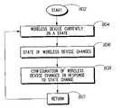
- FIG. 11is an operational flow diagram showing a configuration setting process of a wireless device according to a preferred embodiment of the present invention.
- the operational flow diagram of FIG. 11depicts the process, on a wireless device 106 , of adjusting the configuration settings of wireless device 106 based on the state of the wireless device 106 .
- the operational flow diagram of FIG. 11begins with step 802 and flows directly to step 804 .
- the wireless device 106is currently in a state, such as idle or on-call.
- the on-call state of the wireless device 106indicates that the user is currently engaged in a telephone call.
- the idle state of the wireless device 106indicates that the user is not currently engaged in a telephone call.
- the state of the wireless device 106changes. For example, if the wireless device 106 was in an idle state in step 804 , then the wireless device 106 initiates a telephone call in step 806 and enters the on-call state. In another example, if the wireless device 106 was in an on-call state in step 804 , then the wireless device 106 ends the telephone call in step 806 and proceeds to be in the idle state.
- step 808the settings of the wireless device 106 are adjusted in response to the change in state of step 806 .
- step 810the control of FIG. 11 returns to step 804 .
- Settingsinclude a variety of settings associated with the functions of the wireless device 106 .
- One example of a setting of the wireless device 106is the ring setting.
- the wireless device 106can be configured such that the wireless device 106 performs a variety of actions when an incoming call is detected.
- the wireless device 106can be configured such that the wireless device 106 plays a ring, a series of rings, a beep, a series of beeps or any audio file (such as WAV file or an MP3 file) when an incoming call is detected.
- the wireless device 106can also be configured such that the wireless device 106 vibrates when an incoming call is detected.
- the wireless device 106can be configured such that the wireless device 106 operates in different battery modes, such as normal battery mode and battery save mode, in different situations.
- battery save modethe wireless device 106 is configured such that the wireless device 106 performs battery save tasks such as turning off the backlight of the view screen of the wireless device 106 or powering down certain electrical components of the wireless device 106 .
- normal battery modethe wireless device 106 is configured such that the wireless device 106 operates normally without attempting to save battery power.
- the wireless device 106can be configured such that the input pad of the wireless device 106 is either enabled or disabled. When the input pad of the wireless device 106 is enabled, the wireless device 106 is configured such that information can be entered into the wireless device 106 via the input pad. When the input pad of the wireless device 106 is disabled, the wireless device 106 is configured such that information can no longer be entered into the wireless device 106 via the input pad.
- the wireless device 106can be configured such that use of the wireless device 106 is either enabled or disabled. Typically, the use of the wireless device 106 is disabled only after the wireless device 106 has been idle for a set period of time. When the use of the wireless device 106 is enabled, the wireless device 106 is configured such that the wireless device 106 can be used normally. When the use of the wireless device 106 is disabled or locked, the wireless device 106 is configured such that the wireless device 106 cannot be used for any function.
- the operational flow diagram of FIG. 11depicts the process, on a wireless device 106 , of configuring settings of wireless device 106 based on the placement (or non-placement of) of the wireless device 106 within a holster, such as holster 500 .
- FIG. 11is described below with reference to the above embodiment.
- the operational flow diagram of FIG. 11begins with step 802 and flows directly to step 804 .
- step 804the wireless device 106 is currently in a state, such as the in-holster state and the out-of-holster state.
- step 806the state of the wireless device 106 changes. That is, the wireless device 106 is either removed from the holster 500 or inserted into the holster 500 .
- step 808the configuration settings of the wireless device 106 are adjusted in response to the change in state of step 806 .
- Settingsinclude a variety of settings associated with the functions of the wireless device 106 . Settings are described in greater detail above.
- a group of settingsare adjusted to a first sequence if the wireless device 106 is placed in the holster 500 in step 806 .
- the following sectiondescribes the first sequence of settings.
- the ring setting of the wireless device 106is set to vibrate if the wireless device 106 is not externally powered. That is, the wireless device 106 does not ring when an incoming telephone call is detected. Rather, the wireless device 106 vibrates to notify the user that an incoming call is detected.
- This settingis only adjusted if the wireless device 106 is not externally powered, i.e., when the wireless device 106 is not connected to a charger or other device for providing an electrical current to the wireless device 106 .
- the battery setting of the wireless device 106is set to battery save mode. This setting enables the wireless device 106 to perform battery save tasks such as turning off the backlight of the view screen of the wireless device 106 or powering down certain electrical components of the wireless device 106 .
- the input pad of the wireless device 106is locked or disabled. This setting disables the input pad such that information can no longer be entered into the input pad.
- the device use setting of the wireless device 106is enabled. That is, the wireless device 106 is currently able to be utilized by the user in a normal fashion.
- a group of settingsare adjusted to a second sequence if the wireless device 106 is removed from the holster 500 in step 806 .
- the following sectiondescribes the second sequence of settings.
- the ring setting of the wireless device 106is set to ring. That is, the wireless device 106 rings when an incoming telephone call is detected.
- the battery setting of the wireless device 106is set to normal mode. This setting allows the wireless device 106 to perform tasks normally without having to perform battery save tasks such as turning off the backlight of the view screen of the wireless device 106 or powering down certain electrical components of the wireless device 106 .
- the input pad of the wireless device 106is unlocked or enabled. This setting enables the input pad such that information can be entered into the input pad.
- the device use setting of the wireless device 106is set to be disabled after a time period. That is, after the wireless device 106 has been removed from the holster 500 for a set period of time, the wireless device 106 is disabled such that it can no longer be used for any functions. The wireless device 106 can be removed from the disabled device use setting if the user inserts the wireless device 106 into the holster 500 or inputs a code or password into the input pad of the wireless device 106 .
- step 810the control of FIG. 11 returns to step 804 .
- the configuration of the ring settingis beneficial when the wireless device 106 is in the holster 500 because it allows a user to avoid loud and/or disruptive ringing.
- the wireless device 106is in the holster 500 , there is no need for the device to ring due to the proximity of the wireless device 106 to the user.
- the vibration of the wireless device 106notifies the user of an incoming call.
- the configuration of the ring settingis also advantageous because it eliminates the repeated adjustment of the ring setting by a user when he enters into situation when a ring is not appropriate, such as in a movie theater or a place of worship.
- the configuration of the ring settingis further advantageous because it reduces the number of missed calls due to the removal of a wireless device 106 from a user's person when the wireless device 106 is set to vibrate. Users often miss calls when the wireless device 106 is not attached to a user and the wireless device 106 is set to vibrate.
- the present inventionconfigures the wireless device 106 to ring when it is removed from the holster 500 , thereby allowing the user to hear the wireless device 106 when it receives an incoming call.
- the configuration of the battery settingis beneficial when the wireless device 106 is in the holster 500 because it saves battery life and allows for longer use of the wireless device 106 between charges.
- the wireless device 106is in the holster 500 , there is no need for certain tasks or operations to continue, such as the backlight of the view screen of the wireless device 106 .
- the present inventionconfigures the battery setting of the wireless device 106 to battery save mode when it is inserted into the holster 500 , thereby saving battery life.
- the configuration of the input pad settingis beneficial when the wireless device 106 is in the holster 500 because it eliminates the accidental entry of information via the input pad when the wireless device 106 is not in use.
- the present inventionconfigures the input pad setting of the wireless device 106 to be disabled when it is inserted into the holster 500 , thereby preventing accidental entry of information.
- the configuration of the device use settingis beneficial when the wireless device 106 has been removed from the holster 500 for a set period of time because it prevents the unauthorized use of the wireless device 106 by others.
- the present inventionconfigures the device use setting of the wireless device 106 to be disabled. This security feature prevents the unauthorized use of the wireless device 106 when it has been removed from the holster 500 and is not in the possession of the user.
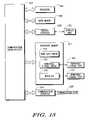
- FIG. 12is an operational flow diagram showing another configuration setting process of the wireless device 106 according to a preferred embodiment of the present invention.
- the operational flow diagram of FIG. 12depicts the process, on a wireless device 106 , of configuring settings of wireless device 106 based on the call status of the wireless device 106 .
- the operational flow diagram of FIG. 12begins with step 842 and flows directly to step 844 .
- step 844it is determined whether there is a headset connected to the wireless device 106 .
- a headsettypically comprises one or two small speakers that fit into one or both ears of a user, a small microphone for receiving audio from the user and a jack for inserting a wire connecting the speakers and microphone to the wireless device 106 .
- a headsetis typically used in conjunction with a wireless device 106 in order to facilitate speaking into a wireless device 106 . The use of a headset eliminates the need for holding the wireless device 106 to a user's head and also allows the hands-free use of the wireless device 106 . If the result of the determination of step 844 is positive, the control flows to step 846 . If the result of the determination of step 844 is negative, the control flows to step 848 .
- step 846the input pad setting of the wireless device 106 is adjusted in response to the result of the determination of step 844 . Namely, the input pad configuration setting of the wireless device 106 is adjusted to be enabled or unlocked. I.e., the input pad is configured to allow for the input of information.
- step 856control flows back to step 844 .
- step 848the call status of the wireless device 106 is determined.
- the wireless device 106is currently in a call state, such as on-call or idle.
- the on-call call status of the wireless device 106indicates that the user is currently engaged in a telephone call.
- the idle call status of the wireless device 106indicates that the user is not currently engaged in a telephone call. If the result of the determination of step 848 is the on-call call status, the control flows to step 850 . If the result of the determination of step 848 is the idle status, the control flows to step 852 .
- step 850it is determined that the call status of the wireless device 106 is on-call.
- step 854the input pad setting of the wireless device 106 is adjusted in response to the result of the determination of step 848 . Namely, the input pad setting of the wireless device 106 is adjusted to be locked or disabled. I.e., the input pad is configured such that the input of information is no longer allowed via the input pad.
- the input pad setting of the wireless device 106can be enabled if the user inputs a code or password into the input pad of the wireless device 106 .
- step 856control flows back to step 844 .
- the configuration of the input pad settingis beneficial when the wireless device 106 is in use because it eliminates the accidental entry of information via the input pad when a user is speaking into the wireless device 106 .
- the present inventionconfigures the input pad setting of the wireless device 106 to be disabled when it is in use, thereby preventing accidental entry of information.
- step 844is optional. If step 844 is not executed, then controls flows from step 842 directly to step 848 .
- the present inventioncan be realized in hardware, software, or a combination of hardware and software in wireless device 106 of FIG. 1 .
- a system according to a preferred embodiment of the present inventioncan be realized in a centralized fashion in one computer system, or in a distributed fashion where different elements are spread across several interconnected computer systems. Any kind of computer system—or other apparatus adapted for carrying out the methods described herein—is suited.
- a typical combination of hardware and softwarecould be a general-purpose computer system with a computer program that, when being loaded and executed, controls the computer system such that it carries out the methods described herein.
- An embodiment of the present inventioncan also be embedded in a computer program product (in wireless device 106 ), which comprises all the features enabling the implementation of the methods described herein, and which, when loaded in a computer system, is able to carry out these methods.
- Computer program means or computer program as used in the present inventionindicates any expression, in any language, code or notation, of a set of instructions intended to cause a system having an information processing capability to perform a particular function either directly or after either or both of the following a) conversion to another language, code or, notation; and b) reproduction in a different material form.
- a computer systemmay include, inter alia, one or more computers and at least a computer-readable medium, allowing a computer system, to read data, instructions, messages or message packets, and other computer-readable information from the computer-readable medium.
- the computer-readable mediummay include non-volatile memory, such as ROM, Flash memory, Disk drive memory, CD-ROM, and other permanent storage. Additionally, a computer-readable medium may include, for example, volatile storage such as RAM, buffers, cache memory, and network circuits.
- the computer-readable mediummay comprise computer-readable information in a transitory state medium such as a network link and/or a network interface, including a wired network or a wireless network, that allow a computer system to read such computer-readable information.
- FIG. 13is a block diagram of a computer system useful for implementing an embodiment of the present invention.
- the computer system of FIG. 13is a more detailed representation of one facet of a wireless device 106 .
- the computer system of FIG. 13includes one or more processors, such as processor 904 .
- the processor 904is connected to a communication infrastructure 902 (e.g., a communications bus, cross-over bar, or network).
- a communication infrastructure 902e.g., a communications bus, cross-over bar, or network.
- Various software embodimentsare described in terms of this exemplary computer system. After reading this description, it will become apparent to a person of ordinary skill in the relevant art(s) how to implement the invention using other computer systems and/or computer architectures.
- the computer systemcan include a display interface 908 that forwards graphics, text, and other data from the communication infrastructure 902 (or from a frame buffer not shown) for display on the display unit 910 .
- the computer systemalso includes a main memory 906 , preferably random access memory (RAM), and may also include a secondary memory 912 .
- the secondary memory 912may include, for example, a hard disk drive 914 and/or a removable storage drive 916 , representing a floppy disk drive, a magnetic tape drive, an optical disk drive, etc.
- the removable storage drive 916reads from and/or writes to a removable storage unit 918 in a manner well known to those having ordinary skill in the art.
- Removable storage unit 918represents a floppy disk, magnetic tape, optical disk, etc., which is read by and written to by removable storage drive 916 .
- the removable storage unit 918includes a computer usable storage medium having stored therein computer software and/or data.
- the secondary memory 912may include other similar means for allowing computer programs or other instructions to be loaded into the computer system.
- Such meansmay include, for example, a removable storage unit 922 and an interface 920 .
- Examples of suchmay include a program cartridge and cartridge interface (such as that found in video game devices), a removable memory chip (such as an EPROM, or PROM) and associated socket, and other removable storage units 922 and interfaces 920 which allow software and data to be transferred from the removable storage unit 922 to the computer system.
- the computer systemmay also include a communications interface 924 .
- Communications interface 924allows software and data to be transferred between the computer system and external devices. Examples of communications interface 924 may include a modem, a network interface (such as an Ethernet card), a communications port, a PCMCIA slot and card, etc.
- Software and data transferred via communications interface 924are in the form of signals which may be, for example, electronic, electromagnetic, optical, or other signals capable of being received by communications interface 924 . These signals are provided to communications interface 924 via a communications path (i.e., channel) 926 .
- This channel 926carries signals and may be implemented using wire or cable, fiber optics, a phone line, a cellular phone link, an RF link, and/or other communications channels.
- the terms “computer program medium,” “computer-usable medium,” “machine-readable medium” and “computer-readable medium”are used to generally refer to media such as main memory 906 and secondary memory 912 , removable storage drive 916 , a hard disk installed in hard disk drive 914 , and signals. These computer program products are means for providing software to the computer system.
- the computer-readable mediumallows the computer system to read data, instructions, messages or message packets, and other computer-readable information from the computer-readable medium.
- the computer-readable mediummay include non-volatile memory, such as Floppy, ROM, Flash memory, Disk drive memory, CD-ROM, and other permanent storage. It is useful, for example, for transporting information, such as data and computer instructions, between computer systems.
- the computer-readable mediummay comprise computer-readable information in a transitory state medium such as a network link and/or a network interface, including a wired network or a wireless network, that allow a computer to read such computer-readable information.
- Computer programsare stored in main memory 906 and/or secondary memory 912 . Computer programs may also be received via communications interface 924 . Such computer programs, when executed, enable the computer system to perform the features of the present invention as discussed herein. In particular, the computer programs, when executed, enable the processor 904 to perform the features of the computer system. Accordingly, such computer programs represent controllers of the computer system.
Landscapes
- Engineering & Computer Science (AREA)
- Computer Networks & Wireless Communication (AREA)
- Signal Processing (AREA)
- Human Computer Interaction (AREA)
- Environmental & Geological Engineering (AREA)
- Telephone Function (AREA)
- Mobile Radio Communication Systems (AREA)
Abstract
Description
Claims (31)
Priority Applications (7)
| Application Number | Priority Date | Filing Date | Title |
|---|---|---|---|
| US10/388,774US6983169B2 (en) | 2003-03-14 | 2003-03-14 | Wireless device allowing for configuration of settings and method therefor |
| PCT/US2004/007204WO2004084016A2 (en) | 2003-03-14 | 2004-03-09 | Wireless device allowing for configuration of settings and method therefor |
| CNA2004800069177ACN1762143A (en) | 2003-03-14 | 2004-03-09 | Wireless device providing configuration of settings and method thereof |
| CN2011100823306ACN102158602A (en) | 2003-03-14 | 2004-03-09 | Wireless device allowing for configuration of settings and method therefor |
| EP04718855AEP1604507A4 (en) | 2003-03-14 | 2004-03-09 | Wireless device allowing for configuration of settings and method therefor |
| KR1020117022739AKR20110120979A (en) | 2003-03-14 | 2004-03-09 | Wireless device with configurable preferences and method |
| KR1020057017085AKR20050113650A (en) | 2003-03-14 | 2004-03-09 | Wireless device allowing for configuration of settings and method therefor |
Applications Claiming Priority (1)
| Application Number | Priority Date | Filing Date | Title |
|---|---|---|---|
| US10/388,774US6983169B2 (en) | 2003-03-14 | 2003-03-14 | Wireless device allowing for configuration of settings and method therefor |
Publications (2)
| Publication Number | Publication Date |
|---|---|
| US20040180649A1 US20040180649A1 (en) | 2004-09-16 |
| US6983169B2true US6983169B2 (en) | 2006-01-03 |
Family
ID=32962125
Family Applications (1)
| Application Number | Title | Priority Date | Filing Date |
|---|---|---|---|
| US10/388,774Expired - LifetimeUS6983169B2 (en) | 2003-03-14 | 2003-03-14 | Wireless device allowing for configuration of settings and method therefor |
Country Status (5)
| Country | Link |
|---|---|
| US (1) | US6983169B2 (en) |
| EP (1) | EP1604507A4 (en) |
| KR (2) | KR20050113650A (en) |
| CN (2) | CN102158602A (en) |
| WO (1) | WO2004084016A2 (en) |
Cited By (20)
| Publication number | Priority date | Publication date | Assignee | Title |
|---|---|---|---|---|
| US20030109275A1 (en)* | 2001-12-07 | 2003-06-12 | Vander Veen Raymond P. | System and method for event-dependent state activation for a dual-mode mobile communication device |
| US20050059435A1 (en)* | 2003-09-17 | 2005-03-17 | Mckee James Scott | Method and apparatus of muting an alert |
| US20060108141A1 (en)* | 2004-11-22 | 2006-05-25 | Torcivia Wayne M | Portable electronic information and/or entertainment rendering devices carrier |
| US20060116183A1 (en)* | 2004-12-01 | 2006-06-01 | Research In Motion Limited | Handheld wireless communication device and holder |
| US20070123296A1 (en)* | 2005-10-11 | 2007-05-31 | Mediatek Inc. | Telecommunication system |
| US20080054039A1 (en)* | 2006-09-05 | 2008-03-06 | Thomas Wulff | Wearable Mobile Computing System |
| US20080191905A1 (en)* | 2007-02-14 | 2008-08-14 | Research In Motion Limited | Method and apparatus for preventing action responsive to accidental keystroke |
| US20080200149A1 (en)* | 2007-02-15 | 2008-08-21 | Ronald Scotte Zinn | Non-visual inbox summary for mobile communication devices |
| US20090075629A1 (en)* | 2007-09-17 | 2009-03-19 | Anita Hogans Simpson | Methods, Systems, and Computer-Readable Media for Detecting a Missing Cellular Device |
| US20120133493A1 (en)* | 2007-02-13 | 2012-05-31 | Research In Motion Limited | System and method for providing improved detection of user inaction |
| US20120214462A1 (en)* | 2011-02-18 | 2012-08-23 | Chu Inchang | Wireless charging method and apparatus |
| US8760294B2 (en) | 2011-01-05 | 2014-06-24 | Blackberry Limited | Electronic device having an electronic compass adapted to detect when the device is in a holster |
| US8930647B1 (en) | 2011-04-06 | 2015-01-06 | P4tents1, LLC | Multiple class memory systems |
| US9158546B1 (en) | 2011-04-06 | 2015-10-13 | P4tents1, LLC | Computer program product for fetching from a first physical memory between an execution of a plurality of threads associated with a second physical memory |
| US9164679B2 (en) | 2011-04-06 | 2015-10-20 | Patents1, Llc | System, method and computer program product for multi-thread operation involving first memory of a first memory class and second memory of a second memory class |
| US9170744B1 (en) | 2011-04-06 | 2015-10-27 | P4tents1, LLC | Computer program product for controlling a flash/DRAM/embedded DRAM-equipped system |
| US9176671B1 (en) | 2011-04-06 | 2015-11-03 | P4tents1, LLC | Fetching data between thread execution in a flash/DRAM/embedded DRAM-equipped system |
| US9417754B2 (en) | 2011-08-05 | 2016-08-16 | P4tents1, LLC | User interface system, method, and computer program product |
| US9716779B1 (en)* | 2016-08-31 | 2017-07-25 | Maxine Nicodemus | Wireless communication system |
| US10712799B2 (en) | 2010-08-06 | 2020-07-14 | Apple Inc. | Intelligent management for an electronic device |
Families Citing this family (38)
| Publication number | Priority date | Publication date | Assignee | Title |
|---|---|---|---|---|
| JP2005020225A (en)* | 2003-06-25 | 2005-01-20 | Casio Comput Co Ltd | Communication terminal apparatus and communication control processing program thereof |
| US20060073819A1 (en)* | 2004-10-04 | 2006-04-06 | Research In Motion Limited | Automatic audio intensity adjustment |
| EP1585292A1 (en)* | 2004-10-04 | 2005-10-12 | Research In Motion Limited | Automatic audio intensity adjustment of a mobile communications device |
| GB2424339B (en)* | 2005-03-14 | 2007-05-16 | Dunhill Alfred Ltd | Case for a mode-switchable mobile communication device |
| US7881283B2 (en) | 2005-07-13 | 2011-02-01 | Research In Motion Limited | Customizability of event notification on telephony-enabled devices |
| EP2164235A3 (en)* | 2005-07-13 | 2011-05-18 | Research In Motion Limited | Customizability of event notification on telephony-enabled devices |
| US7714265B2 (en) | 2005-09-30 | 2010-05-11 | Apple Inc. | Integrated proximity sensor and light sensor |
| US7728316B2 (en)* | 2005-09-30 | 2010-06-01 | Apple Inc. | Integrated proximity sensor and light sensor |
| US7633076B2 (en) | 2005-09-30 | 2009-12-15 | Apple Inc. | Automated response to and sensing of user activity in portable devices |
| JP5110805B2 (en)* | 2005-11-18 | 2012-12-26 | キヤノン株式会社 | Communication terminal, communication method and program capable of wired and wireless communication |
| US20070167190A1 (en)* | 2006-01-18 | 2007-07-19 | Research In Motion Limited | Component-based mobile device |
| KR100748443B1 (en)* | 2006-02-06 | 2007-08-10 | (주) 엘지텔레콤 | How to automatically terminate the application of the portable device using motion detection and a computer-readable recording medium therefor |
| JP4595886B2 (en)* | 2006-05-24 | 2010-12-08 | 日本電気株式会社 | Device unauthorized use prevention system and device |
| KR100734203B1 (en)* | 2006-06-30 | 2007-07-02 | 주식회사 스타칩 | Communication environment setting device with integrated interfacing information connected to mobile phone and setting method |
| EP1879364A1 (en)* | 2006-07-12 | 2008-01-16 | Research In Motion Limited | Holster for an electronic hand held device |
| US20080012706A1 (en)* | 2006-07-12 | 2008-01-17 | Research In Motion Limited | Holster for hand held electronic device |
| US8006002B2 (en) | 2006-12-12 | 2011-08-23 | Apple Inc. | Methods and systems for automatic configuration of peripherals |
| US8031164B2 (en)* | 2007-01-05 | 2011-10-04 | Apple Inc. | Backlight and ambient light sensor system |
| US8698727B2 (en)* | 2007-01-05 | 2014-04-15 | Apple Inc. | Backlight and ambient light sensor system |
| US7957762B2 (en)* | 2007-01-07 | 2011-06-07 | Apple Inc. | Using ambient light sensor to augment proximity sensor output |
| EP1959332A1 (en)* | 2007-02-13 | 2008-08-20 | Research In Motion Limited | System and method for providing improved detection of user inaction |
| US8693877B2 (en)* | 2007-03-09 | 2014-04-08 | Apple Inc. | Integrated infrared receiver and emitter for multiple functionalities |
| TWI364204B (en)* | 2007-05-18 | 2012-05-11 | Quanta Comp Inc | System and method for bridging file system between two different processor in mobile phone |
| JP4628483B2 (en)* | 2008-07-15 | 2011-02-09 | パナソニック株式会社 | Portable device and position specifying method thereof |
| US8831509B2 (en) | 2011-01-31 | 2014-09-09 | Blackberry Limited | Mobile device having enhanced in-holster power saving features using NFC and related methods |
| US8983373B2 (en) | 2011-06-10 | 2015-03-17 | Blackberry Limited | Communications system providing enhanced mobile device holder detection based upon NFC communication and related methods |
| US8958856B2 (en)* | 2011-07-15 | 2015-02-17 | Blackberry Limited | Holster profile detection via electric-field proximity sensor technology |
| US8792824B2 (en) | 2012-02-08 | 2014-07-29 | Blackberry Limited | Mobile communications device providing near field communication (NFC) low power operating features and related methods |
| US9231655B2 (en) | 2012-04-06 | 2016-01-05 | Broadcom Corporation | System and method for power control in a physical layer device |
| US9692643B2 (en)* | 2012-06-28 | 2017-06-27 | Google Inc. | Systems and methods for automatic modification of device configuration values |
| US9146304B2 (en) | 2012-09-10 | 2015-09-29 | Apple Inc. | Optical proximity sensor with ambient light and temperature compensation |
| US9602645B2 (en)* | 2013-05-16 | 2017-03-21 | Blackberry Limited | Smart covering for mobile communications device |
| US9857835B2 (en) | 2014-06-27 | 2018-01-02 | Xiaomi Inc. | Protective cover and device having the protective cover |
| CN104127010B (en)* | 2014-06-27 | 2016-06-22 | 小米科技有限责任公司 | Protection set and the equipment with protection set |
| CN104244182A (en)* | 2014-09-13 | 2014-12-24 | 北京智谷技术服务有限公司 | Method and device for determining position of mobile device and mobile device |
| US10349259B2 (en)* | 2016-09-23 | 2019-07-09 | Apple Inc. | Broadcasting a device state in a wireless communication network |
| KR102334530B1 (en)* | 2020-02-11 | 2021-12-07 | 주식회사 안소프트 | Contents providing method capable of adjusting a volume setting before playing contents on hold in receiver |
| KR102290033B1 (en)* | 2020-02-11 | 2021-08-18 | 주식회사 안소프트 | Contents providing method capable of adjusting a volume setting before playing contents on hold in transmitter |
Citations (12)
| Publication number | Priority date | Publication date | Assignee | Title |
|---|---|---|---|---|
| US5542105A (en)* | 1994-10-07 | 1996-07-30 | Motorola, Inc. | Position sense radio carry case apparatus and method of using same |
| US5884156A (en)* | 1996-02-20 | 1999-03-16 | Geotek Communications Inc. | Portable communication device |
| US6021332A (en)* | 1997-04-01 | 2000-02-01 | Motorola, Inc. | Multi-mode radiotelephone having a multiple battery arrangement |
| US6021310A (en)* | 1997-09-30 | 2000-02-01 | Thorne; Robert | Computer pager device |
| US6115620A (en)* | 1998-05-20 | 2000-09-05 | Motorola, Inc. | Mode-switchable portable communication device and method therefor |
| US6397085B1 (en)* | 1999-02-22 | 2002-05-28 | Sanyo Electronic Co., Ltd. | Telephone with key-click sound volume control |
| US20020107009A1 (en)* | 1997-03-14 | 2002-08-08 | Christian Kraft | Telephone with automatic mode selection |
| US6449492B1 (en)* | 1999-12-02 | 2002-09-10 | Qualcomm Incorporated | Apparatus and method for preventing inadvertant operation of a manual input device |
| US20030153355A1 (en)* | 2001-09-20 | 2003-08-14 | Peter Warren | Input-output device with universal phone port |
| US6643528B1 (en) | 2000-09-08 | 2003-11-04 | Mobigence, Inc. | Integrated radiotelephone holster and audio appliance |
| US20040070499A1 (en)* | 2002-10-10 | 2004-04-15 | Sawinski John P. | Method and apparatus for reducing the likelihood of losing a portable electronic device |
| US20040110544A1 (en)* | 2001-04-03 | 2004-06-10 | Masayuki Oyagi | Cradle, security system, telephone, and monitoring method |
Family Cites Families (7)
| Publication number | Priority date | Publication date | Assignee | Title |
|---|---|---|---|---|
| JPH0666825B2 (en)* | 1988-09-08 | 1994-08-24 | シャープ株式会社 | Cordless phone |
| CA2055264A1 (en)* | 1991-11-12 | 1993-05-13 | Gyles Panther | Pager with automatic detection of insertion into holster |
| GB2318673A (en)* | 1996-10-23 | 1998-04-29 | Nokia Mobile Phones Ltd | Radiotelephone proximity detector |
| JPH10271199A (en)* | 1997-03-27 | 1998-10-09 | Nippon Denki Ido Tsushin Kk | Portable telephone set |
| JPH11239203A (en)* | 1998-02-23 | 1999-08-31 | Canon Inc | Portable terminal device and lighting control method thereof |
| JP4201443B2 (en)* | 1999-11-05 | 2008-12-24 | パナソニック株式会社 | Folding mobile phone device |
| US7536562B2 (en)* | 2002-10-17 | 2009-05-19 | Research In Motion Limited | System and method of security function activation for a mobile electronic device |
- 2003
- 2003-03-14USUS10/388,774patent/US6983169B2/ennot_activeExpired - Lifetime
- 2004
- 2004-03-09WOPCT/US2004/007204patent/WO2004084016A2/enactiveApplication Filing
- 2004-03-09KRKR1020057017085Apatent/KR20050113650A/ennot_activeCeased
- 2004-03-09CNCN2011100823306Apatent/CN102158602A/enactivePending
- 2004-03-09KRKR1020117022739Apatent/KR20110120979A/ennot_activeCeased
- 2004-03-09CNCNA2004800069177Apatent/CN1762143A/enactivePending
- 2004-03-09EPEP04718855Apatent/EP1604507A4/ennot_activeWithdrawn
Patent Citations (12)
| Publication number | Priority date | Publication date | Assignee | Title |
|---|---|---|---|---|
| US5542105A (en)* | 1994-10-07 | 1996-07-30 | Motorola, Inc. | Position sense radio carry case apparatus and method of using same |
| US5884156A (en)* | 1996-02-20 | 1999-03-16 | Geotek Communications Inc. | Portable communication device |
| US20020107009A1 (en)* | 1997-03-14 | 2002-08-08 | Christian Kraft | Telephone with automatic mode selection |
| US6021332A (en)* | 1997-04-01 | 2000-02-01 | Motorola, Inc. | Multi-mode radiotelephone having a multiple battery arrangement |
| US6021310A (en)* | 1997-09-30 | 2000-02-01 | Thorne; Robert | Computer pager device |
| US6115620A (en)* | 1998-05-20 | 2000-09-05 | Motorola, Inc. | Mode-switchable portable communication device and method therefor |
| US6397085B1 (en)* | 1999-02-22 | 2002-05-28 | Sanyo Electronic Co., Ltd. | Telephone with key-click sound volume control |
| US6449492B1 (en)* | 1999-12-02 | 2002-09-10 | Qualcomm Incorporated | Apparatus and method for preventing inadvertant operation of a manual input device |
| US6643528B1 (en) | 2000-09-08 | 2003-11-04 | Mobigence, Inc. | Integrated radiotelephone holster and audio appliance |
| US20040110544A1 (en)* | 2001-04-03 | 2004-06-10 | Masayuki Oyagi | Cradle, security system, telephone, and monitoring method |
| US20030153355A1 (en)* | 2001-09-20 | 2003-08-14 | Peter Warren | Input-output device with universal phone port |
| US20040070499A1 (en)* | 2002-10-10 | 2004-04-15 | Sawinski John P. | Method and apparatus for reducing the likelihood of losing a portable electronic device |
Cited By (92)
| Publication number | Priority date | Publication date | Assignee | Title |
|---|---|---|---|---|
| US20070207829A1 (en)* | 2001-12-07 | 2007-09-06 | Vander Veen Raymond P | System and method for event-dependent state activation for a dual-mode mobile communication device |
| US20030109275A1 (en)* | 2001-12-07 | 2003-06-12 | Vander Veen Raymond P. | System and method for event-dependent state activation for a dual-mode mobile communication device |
| US7076267B2 (en)* | 2001-12-07 | 2006-07-11 | Research In Motion Limited | System and method for event-dependent state activation for a dual-mode mobile communication device |
| US20060252464A1 (en)* | 2001-12-07 | 2006-11-09 | Research In Motion Limited | System and method for event-dependent state activation for a dual-mode mobile communication device |
| US7519388B2 (en) | 2001-12-07 | 2009-04-14 | Research In Motion Limited | System and method for event-dependent state activation for a dual-mode mobile communication device |
| US7231226B2 (en) | 2001-12-07 | 2007-06-12 | Research In Motion Limited | System and method for event-dependent state activation for a dual-mode mobile communication device |
| US20050059435A1 (en)* | 2003-09-17 | 2005-03-17 | Mckee James Scott | Method and apparatus of muting an alert |
| US7027840B2 (en)* | 2003-09-17 | 2006-04-11 | Motorola, Inc. | Method and apparatus of muting an alert |
| US20060108141A1 (en)* | 2004-11-22 | 2006-05-25 | Torcivia Wayne M | Portable electronic information and/or entertainment rendering devices carrier |
| US7161086B2 (en)* | 2004-11-22 | 2007-01-09 | Wayne M. Torcivia | Portable electronic information and/or entertainment rendering devices carrier |
| US7555326B2 (en) | 2004-12-01 | 2009-06-30 | Research In Motion Limited | Handheld wireless communication device and holder |
| US7454239B2 (en)* | 2004-12-01 | 2008-11-18 | Research In Motion Limited | Handheld wireless communication device and holder |
| US20090029750A1 (en)* | 2004-12-01 | 2009-01-29 | Research In Motion Limited | Handheld wireless communication device and holder |
| US20060116183A1 (en)* | 2004-12-01 | 2006-06-01 | Research In Motion Limited | Handheld wireless communication device and holder |
| US20070123296A1 (en)* | 2005-10-11 | 2007-05-31 | Mediatek Inc. | Telecommunication system |
| US20080054039A1 (en)* | 2006-09-05 | 2008-03-06 | Thomas Wulff | Wearable Mobile Computing System |
| US8260384B2 (en)* | 2006-09-05 | 2012-09-04 | Symbol Technologies, Inc. | Wearable mobile computing system |
| US20120133493A1 (en)* | 2007-02-13 | 2012-05-31 | Research In Motion Limited | System and method for providing improved detection of user inaction |
| US8665105B2 (en)* | 2007-02-13 | 2014-03-04 | Blackberry Limited | System and method for providing improved detection of user inaction |
| US20080191905A1 (en)* | 2007-02-14 | 2008-08-14 | Research In Motion Limited | Method and apparatus for preventing action responsive to accidental keystroke |
| US8359011B2 (en)* | 2007-02-15 | 2013-01-22 | Research In Motion Limited | Non-visual inbox summary for mobile communication devices |
| US20080200149A1 (en)* | 2007-02-15 | 2008-08-21 | Ronald Scotte Zinn | Non-visual inbox summary for mobile communication devices |
| US8190125B2 (en)* | 2007-09-17 | 2012-05-29 | At&T Intellectual Property I, L.P. | Methods, systems, and computer-readable media for detecting a missing cellular device |
| US20090075629A1 (en)* | 2007-09-17 | 2009-03-19 | Anita Hogans Simpson | Methods, Systems, and Computer-Readable Media for Detecting a Missing Cellular Device |
| US10712799B2 (en) | 2010-08-06 | 2020-07-14 | Apple Inc. | Intelligent management for an electronic device |
| US8760294B2 (en) | 2011-01-05 | 2014-06-24 | Blackberry Limited | Electronic device having an electronic compass adapted to detect when the device is in a holster |
| US9599680B2 (en) | 2011-01-05 | 2017-03-21 | Blackberry Limited | Electronic device having an electronic compass adapted to detect when the device is in a holster |
| US20120214462A1 (en)* | 2011-02-18 | 2012-08-23 | Chu Inchang | Wireless charging method and apparatus |
| US8903456B2 (en)* | 2011-02-18 | 2014-12-02 | Lg Electronics Inc. | Wireless charging method and apparatus |
| US9164679B2 (en) | 2011-04-06 | 2015-10-20 | Patents1, Llc | System, method and computer program product for multi-thread operation involving first memory of a first memory class and second memory of a second memory class |
| US9170744B1 (en) | 2011-04-06 | 2015-10-27 | P4tents1, LLC | Computer program product for controlling a flash/DRAM/embedded DRAM-equipped system |
| US9176671B1 (en) | 2011-04-06 | 2015-11-03 | P4tents1, LLC | Fetching data between thread execution in a flash/DRAM/embedded DRAM-equipped system |
| US9182914B1 (en) | 2011-04-06 | 2015-11-10 | P4tents1, LLC | System, method and computer program product for multi-thread operation involving first memory of a first memory class and second memory of a second memory class |
| US9189442B1 (en) | 2011-04-06 | 2015-11-17 | P4tents1, LLC | Fetching data between thread execution in a flash/DRAM/embedded DRAM-equipped system |
| US9195395B1 (en) | 2011-04-06 | 2015-11-24 | P4tents1, LLC | Flash/DRAM/embedded DRAM-equipped system and method |
| US9223507B1 (en) | 2011-04-06 | 2015-12-29 | P4tents1, LLC | System, method and computer program product for fetching data between an execution of a plurality of threads |
| US9158546B1 (en) | 2011-04-06 | 2015-10-13 | P4tents1, LLC | Computer program product for fetching from a first physical memory between an execution of a plurality of threads associated with a second physical memory |
| US8930647B1 (en) | 2011-04-06 | 2015-01-06 | P4tents1, LLC | Multiple class memory systems |
| US10209806B1 (en) | 2011-08-05 | 2019-02-19 | P4tents1, LLC | Tri-state gesture-equipped touch screen system, method, and computer program product |
| US10606396B1 (en) | 2011-08-05 | 2020-03-31 | P4tents1, LLC | Gesture-equipped touch screen methods for duration-based functions |
| US10120480B1 (en) | 2011-08-05 | 2018-11-06 | P4tents1, LLC | Application-specific pressure-sensitive touch screen system, method, and computer program product |
| US10146353B1 (en) | 2011-08-05 | 2018-12-04 | P4tents1, LLC | Touch screen system, method, and computer program product |
| US10156921B1 (en) | 2011-08-05 | 2018-12-18 | P4tents1, LLC | Tri-state gesture-equipped touch screen system, method, and computer program product |
| US10162448B1 (en) | 2011-08-05 | 2018-12-25 | P4tents1, LLC | System, method, and computer program product for a pressure-sensitive touch screen for messages |
| US10203794B1 (en) | 2011-08-05 | 2019-02-12 | P4tents1, LLC | Pressure-sensitive home interface system, method, and computer program product |
| US10209807B1 (en) | 2011-08-05 | 2019-02-19 | P4tents1, LLC | Pressure sensitive touch screen system, method, and computer program product for hyperlinks |
| US11740727B1 (en) | 2011-08-05 | 2023-08-29 | P4Tents1 Llc | Devices, methods, and graphical user interfaces for manipulating user interface objects with visual and/or haptic feedback |
| US10209809B1 (en) | 2011-08-05 | 2019-02-19 | P4tents1, LLC | Pressure-sensitive touch screen system, method, and computer program product for objects |
| US10209808B1 (en) | 2011-08-05 | 2019-02-19 | P4tents1, LLC | Pressure-based interface system, method, and computer program product with virtual display layers |
| US10222891B1 (en) | 2011-08-05 | 2019-03-05 | P4tents1, LLC | Setting interface system, method, and computer program product for a multi-pressure selection touch screen |
| US10222892B1 (en) | 2011-08-05 | 2019-03-05 | P4tents1, LLC | System, method, and computer program product for a multi-pressure selection touch screen |
| US10222895B1 (en) | 2011-08-05 | 2019-03-05 | P4tents1, LLC | Pressure-based touch screen system, method, and computer program product with virtual display layers |
| US10222894B1 (en) | 2011-08-05 | 2019-03-05 | P4tents1, LLC | System, method, and computer program product for a multi-pressure selection touch screen |
| US10222893B1 (en) | 2011-08-05 | 2019-03-05 | P4tents1, LLC | Pressure-based touch screen system, method, and computer program product with virtual display layers |
| US10275086B1 (en) | 2011-08-05 | 2019-04-30 | P4tents1, LLC | Gesture-equipped touch screen system, method, and computer program product |
| US10275087B1 (en) | 2011-08-05 | 2019-04-30 | P4tents1, LLC | Devices, methods, and graphical user interfaces for manipulating user interface objects with visual and/or haptic feedback |
| US10338736B1 (en) | 2011-08-05 | 2019-07-02 | P4tents1, LLC | Devices, methods, and graphical user interfaces for manipulating user interface objects with visual and/or haptic feedback |
| US10345961B1 (en) | 2011-08-05 | 2019-07-09 | P4tents1, LLC | Devices and methods for navigating between user interfaces |
| US10365758B1 (en) | 2011-08-05 | 2019-07-30 | P4tents1, LLC | Devices, methods, and graphical user interfaces for manipulating user interface objects with visual and/or haptic feedback |
| US10386960B1 (en) | 2011-08-05 | 2019-08-20 | P4tents1, LLC | Devices, methods, and graphical user interfaces for manipulating user interface objects with visual and/or haptic feedback |
| US10521047B1 (en) | 2011-08-05 | 2019-12-31 | P4tents1, LLC | Gesture-equipped touch screen system, method, and computer program product |
| US10534474B1 (en) | 2011-08-05 | 2020-01-14 | P4tents1, LLC | Gesture-equipped touch screen system, method, and computer program product |
| US10540039B1 (en) | 2011-08-05 | 2020-01-21 | P4tents1, LLC | Devices and methods for navigating between user interface |
| US10551966B1 (en) | 2011-08-05 | 2020-02-04 | P4tents1, LLC | Gesture-equipped touch screen system, method, and computer program product |
| US10592039B1 (en) | 2011-08-05 | 2020-03-17 | P4tents1, LLC | Gesture-equipped touch screen system, method, and computer program product for displaying multiple active applications |
| US10031607B1 (en) | 2011-08-05 | 2018-07-24 | P4tents1, LLC | System, method, and computer program product for a multi-pressure selection touch screen |
| US10642413B1 (en) | 2011-08-05 | 2020-05-05 | P4tents1, LLC | Gesture-equipped touch screen system, method, and computer program product |
| US10649581B1 (en) | 2011-08-05 | 2020-05-12 | P4tents1, LLC | Devices, methods, and graphical user interfaces for manipulating user interface objects with visual and/or haptic feedback |
| US10649571B1 (en) | 2011-08-05 | 2020-05-12 | P4tents1, LLC | Devices, methods, and graphical user interfaces for manipulating user interface objects with visual and/or haptic feedback |
| US10649578B1 (en) | 2011-08-05 | 2020-05-12 | P4tents1, LLC | Gesture-equipped touch screen system, method, and computer program product |
| US10649579B1 (en) | 2011-08-05 | 2020-05-12 | P4tents1, LLC | Devices, methods, and graphical user interfaces for manipulating user interface objects with visual and/or haptic feedback |
| US10649580B1 (en) | 2011-08-05 | 2020-05-12 | P4tents1, LLC | Devices, methods, and graphical use interfaces for manipulating user interface objects with visual and/or haptic feedback |
| US10656759B1 (en) | 2011-08-05 | 2020-05-19 | P4tents1, LLC | Devices, methods, and graphical user interfaces for manipulating user interface objects with visual and/or haptic feedback |
| US10656754B1 (en) | 2011-08-05 | 2020-05-19 | P4tents1, LLC | Devices and methods for navigating between user interfaces |
| US10656755B1 (en) | 2011-08-05 | 2020-05-19 | P4tents1, LLC | Gesture-equipped touch screen system, method, and computer program product |
| US10656752B1 (en) | 2011-08-05 | 2020-05-19 | P4tents1, LLC | Gesture-equipped touch screen system, method, and computer program product |
| US10656758B1 (en) | 2011-08-05 | 2020-05-19 | P4tents1, LLC | Gesture-equipped touch screen system, method, and computer program product |
| US10656753B1 (en) | 2011-08-05 | 2020-05-19 | P4tents1, LLC | Gesture-equipped touch screen system, method, and computer program product |
| US10656756B1 (en) | 2011-08-05 | 2020-05-19 | P4tents1, LLC | Gesture-equipped touch screen system, method, and computer program product |
| US10656757B1 (en) | 2011-08-05 | 2020-05-19 | P4tents1, LLC | Gesture-equipped touch screen system, method, and computer program product |
| US10664097B1 (en) | 2011-08-05 | 2020-05-26 | P4tents1, LLC | Devices, methods, and graphical user interfaces for manipulating user interface objects with visual and/or haptic feedback |
| US10671212B1 (en) | 2011-08-05 | 2020-06-02 | P4tents1, LLC | Gesture-equipped touch screen system, method, and computer program product |
| US10671213B1 (en) | 2011-08-05 | 2020-06-02 | P4tents1, LLC | Devices, methods, and graphical user interfaces for manipulating user interface objects with visual and/or haptic feedback |
| US9417754B2 (en) | 2011-08-05 | 2016-08-16 | P4tents1, LLC | User interface system, method, and computer program product |
| US10725581B1 (en) | 2011-08-05 | 2020-07-28 | P4tents1, LLC | Devices, methods and graphical user interfaces for manipulating user interface objects with visual and/or haptic feedback |
| US10782819B1 (en) | 2011-08-05 | 2020-09-22 | P4tents1, LLC | Gesture-equipped touch screen system, method, and computer program product |
| US10788931B1 (en) | 2011-08-05 | 2020-09-29 | P4tents1, LLC | Devices, methods, and graphical user interfaces for manipulating user interface objects with visual and/or haptic feedback |
| US10838542B1 (en) | 2011-08-05 | 2020-11-17 | P4tents1, LLC | Gesture-equipped touch screen system, method, and computer program product |
| US10936114B1 (en) | 2011-08-05 | 2021-03-02 | P4tents1, LLC | Gesture-equipped touch screen system, method, and computer program product |
| US10996787B1 (en) | 2011-08-05 | 2021-05-04 | P4tents1, LLC | Gesture-equipped touch screen system, method, and computer program product |
| US11061503B1 (en) | 2011-08-05 | 2021-07-13 | P4tents1, LLC | Devices, methods, and graphical user interfaces for manipulating user interface objects with visual and/or haptic feedback |
| US9716779B1 (en)* | 2016-08-31 | 2017-07-25 | Maxine Nicodemus | Wireless communication system |
Also Published As
| Publication number | Publication date |
|---|---|
| CN102158602A (en) | 2011-08-17 |
| WO2004084016A2 (en) | 2004-09-30 |
| WO2004084016A3 (en) | 2005-01-06 |
| US20040180649A1 (en) | 2004-09-16 |
| KR20110120979A (en) | 2011-11-04 |
| CN1762143A (en) | 2006-04-19 |
| EP1604507A4 (en) | 2010-05-19 |
| KR20050113650A (en) | 2005-12-02 |
| EP1604507A2 (en) | 2005-12-14 |
Similar Documents
| Publication | Publication Date | Title |
|---|---|---|
| US6983169B2 (en) | Wireless device allowing for configuration of settings and method therefor | |
| US7580725B2 (en) | Intelligent wireless device mode changing device and method | |
| US8452343B2 (en) | Portable terminal | |
| US20050272408A1 (en) | Method for personal notification indication | |
| EP1627542B1 (en) | Method and radio terminal equipment arrangement of indicating incoming connection | |
| US20060073819A1 (en) | Automatic audio intensity adjustment | |
| WO2013170522A1 (en) | Ringtone adjustment and processing method and device | |
| US20030100261A1 (en) | Apparatus and method for delayed answering of mobile telephones | |
| US6547620B1 (en) | Communication apparatus, memory medium and method | |
| US20040214594A1 (en) | Device having smart user alert | |
| JP2009206868A (en) | Portable communication terminal, incoming call notification method | |
| US20100034395A1 (en) | Adaptive ring level | |
| US20070117594A1 (en) | Method and system for selective deactivation of a main display | |
| CN118984350A (en) | Audio output method, electronic device and storage medium | |
| CA2573480C (en) | Method of call routing in a public/private communication system | |
| US20060121954A1 (en) | Power consumption management for the playback of multimedia messages | |
| JP3827521B2 (en) | Information portable terminal device | |
| JP3573998B2 (en) | Mobile phone equipment | |
| KR100771160B1 (en) | How to Control Spam Calls on Mobile Devices | |
| JP2012049896A (en) | Terminal device, incoming call notification method thereof and program for the same | |
| KR100406252B1 (en) | Mobile terminal capable of inactivating a receiving call and inactivating method thereof | |
| EP1585292A1 (en) | Automatic audio intensity adjustment of a mobile communications device | |
| JPH1117609A (en) | Composite wireless portable terminal device | |
| JP2005236790A (en) | Mobile communication terminal unit and base station radio device | |
| JP3548044B2 (en) | Telephone equipment |
Legal Events
| Date | Code | Title | Description |
|---|---|---|---|
| AS | Assignment | Owner name:MOTOROLA, INC., ILLINOIS Free format text:ASSIGNMENT OF ASSIGNORS INTEREST;ASSIGNORS:VOGEL, DAVID RICHARD;WILL, ADAM MARK;WANDT, HENRY;AND OTHERS;REEL/FRAME:013891/0978;SIGNING DATES FROM 20030311 TO 20030313 | |
| STCF | Information on status: patent grant | Free format text:PATENTED CASE | |
| FPAY | Fee payment | Year of fee payment:4 | |
| AS | Assignment | Owner name:MOTOROLA MOBILITY, INC, ILLINOIS Free format text:ASSIGNMENT OF ASSIGNORS INTEREST;ASSIGNOR:MOTOROLA, INC;REEL/FRAME:025673/0558 Effective date:20100731 | |
| AS | Assignment | Owner name:MOTOROLA MOBILITY LLC, ILLINOIS Free format text:CHANGE OF NAME;ASSIGNOR:MOTOROLA MOBILITY, INC.;REEL/FRAME:029216/0282 Effective date:20120622 | |
| FPAY | Fee payment | Year of fee payment:8 | |
| AS | Assignment | Owner name:GOOGLE TECHNOLOGY HOLDINGS LLC, CALIFORNIA Free format text:ASSIGNMENT OF ASSIGNORS INTEREST;ASSIGNOR:MOTOROLA MOBILITY LLC;REEL/FRAME:034227/0095 Effective date:20141028 | |
| FEPP | Fee payment procedure | Free format text:PAYOR NUMBER ASSIGNED (ORIGINAL EVENT CODE: ASPN); ENTITY STATUS OF PATENT OWNER: LARGE ENTITY | |
| FPAY | Fee payment | Year of fee payment:12 |