US6982740B2 - Reduced area imaging devices utilizing selected charge integration periods - Google Patents
Reduced area imaging devices utilizing selected charge integration periodsDownload PDFInfo
- Publication number
- US6982740B2 US6982740B2US09/971,749US97174901AUS6982740B2US 6982740 B2US6982740 B2US 6982740B2US 97174901 AUS97174901 AUS 97174901AUS 6982740 B2US6982740 B2US 6982740B2
- Authority
- US
- United States
- Prior art keywords
- image sensor
- array
- pixels
- video signal
- circuit board
- Prior art date
- Legal status (The legal status is an assumption and is not a legal conclusion. Google has not performed a legal analysis and makes no representation as to the accuracy of the status listed.)
- Expired - Fee Related, expires
Links
- 238000003384imaging methodMethods0.000titleclaimsabstractdescription112
- 230000010354integrationEffects0.000titleclaimsabstractdescription80
- 238000000034methodMethods0.000claimsabstractdescription32
- 239000004020conductorSubstances0.000claimsdescription54
- 230000002708enhancing effectEffects0.000claimsdescription6
- 230000008569processEffects0.000abstractdescription15
- 238000001839endoscopyMethods0.000abstractdescription10
- 238000001356surgical procedureMethods0.000abstractdescription6
- 238000012545processingMethods0.000description57
- 239000007787solidSubstances0.000description11
- 238000010586diagramMethods0.000description10
- 238000005516engineering processMethods0.000description9
- 239000000835fiberSubstances0.000description8
- 230000008901benefitEffects0.000description7
- 238000001917fluorescence detectionMethods0.000description7
- 230000006870functionEffects0.000description7
- 230000003902lesionEffects0.000description7
- 239000000758substrateSubstances0.000description7
- 238000012546transferMethods0.000description7
- 206010028980NeoplasmDiseases0.000description6
- 238000003491arrayMethods0.000description5
- 201000011510cancerDiseases0.000description5
- 238000006243chemical reactionMethods0.000description5
- 238000010276constructionMethods0.000description5
- 238000011161developmentMethods0.000description5
- 230000018109developmental processEffects0.000description5
- 238000002347injectionMethods0.000description5
- 239000007924injectionSubstances0.000description5
- 238000004519manufacturing processMethods0.000description5
- 230000001965increasing effectEffects0.000description4
- 230000003211malignant effectEffects0.000description4
- 238000012216screeningMethods0.000description4
- 239000004065semiconductorSubstances0.000description4
- 238000011282treatmentMethods0.000description4
- ZGXJTSGNIOSYLO-UHFFFAOYSA-N88755TAZ87Chemical compoundNCC(=O)CCC(O)=OZGXJTSGNIOSYLO-UHFFFAOYSA-N0.000description3
- KSFOVUSSGSKXFI-GAQDCDSVSA-NCC1=C/2NC(\C=C3/N=C(/C=C4\N\C(=C/C5=N/C(=C\2)/C(C=C)=C5C)C(C=C)=C4C)C(C)=C3CCC(O)=O)=C1CCC(O)=OChemical compoundCC1=C/2NC(\C=C3/N=C(/C=C4\N\C(=C/C5=N/C(=C\2)/C(C=C)=C5C)C(C=C)=C4C)C(C)=C3CCC(O)=O)=C1CCC(O)=OKSFOVUSSGSKXFI-GAQDCDSVSA-N0.000description3
- 229960002749aminolevulinic acidDrugs0.000description3
- 239000003990capacitorSubstances0.000description3
- 210000001072colonAnatomy0.000description3
- 239000003086colorantSubstances0.000description3
- 230000000295complement effectEffects0.000description3
- 239000002131composite materialSubstances0.000description3
- 230000000875corresponding effectEffects0.000description3
- 229910044991metal oxideInorganic materials0.000description3
- 150000004706metal oxidesChemical class0.000description3
- 229950003776protoporphyrinDrugs0.000description3
- 241000933095Neotragus moschatusSpecies0.000description2
- 241000183290Scleropages leichardtiSpecies0.000description2
- 230000015572biosynthetic processEffects0.000description2
- 239000000872bufferSubstances0.000description2
- 238000001444catalytic combustion detectionMethods0.000description2
- 238000004113cell cultureMethods0.000description2
- 150000001875compoundsChemical class0.000description2
- 238000001514detection methodMethods0.000description2
- 238000002674endoscopic surgeryMethods0.000description2
- 239000012530fluidSubstances0.000description2
- 238000010348incorporationMethods0.000description2
- 208000014674injuryDiseases0.000description2
- 239000000463materialSubstances0.000description2
- 238000012986modificationMethods0.000description2
- 230000004048modificationEffects0.000description2
- 230000001681protective effectEffects0.000description2
- 230000008733traumaEffects0.000description2
- 230000000007visual effectEffects0.000description2
- 206010009944Colon cancerDiseases0.000description1
- WHXSMMKQMYFTQS-UHFFFAOYSA-NLithiumChemical compound[Li]WHXSMMKQMYFTQS-UHFFFAOYSA-N0.000description1
- 230000003213activating effectEffects0.000description1
- 230000003321amplificationEffects0.000description1
- 238000004458analytical methodMethods0.000description1
- 238000013459approachMethods0.000description1
- 239000006143cell culture mediumSubstances0.000description1
- 238000002512chemotherapyMethods0.000description1
- 208000029742colonic neoplasmDiseases0.000description1
- 230000003750conditioning effectEffects0.000description1
- 230000001276controlling effectEffects0.000description1
- 230000002596correlated effectEffects0.000description1
- 230000008878couplingEffects0.000description1
- 238000010168coupling processMethods0.000description1
- 238000005859coupling reactionMethods0.000description1
- 239000013078crystalSubstances0.000description1
- 238000013461designMethods0.000description1
- 230000001066destructive effectEffects0.000description1
- 238000003745diagnosisMethods0.000description1
- 239000000975dyeSubstances0.000description1
- 238000011156evaluationMethods0.000description1
- 230000005284excitationEffects0.000description1
- 238000011010flushing procedureMethods0.000description1
- 239000007789gasSubstances0.000description1
- 238000011835investigationMethods0.000description1
- 239000007788liquidSubstances0.000description1
- 229910052744lithiumInorganic materials0.000description1
- 239000003550markerSubstances0.000description1
- 230000007246mechanismEffects0.000description1
- 238000012544monitoring processMethods0.000description1
- 238000003199nucleic acid amplification methodMethods0.000description1
- 238000002428photodynamic therapyMethods0.000description1
- 239000002243precursorSubstances0.000description1
- 239000010453quartzSubstances0.000description1
- 238000005070samplingMethods0.000description1
- 230000035945sensitivityEffects0.000description1
- 238000000926separation methodMethods0.000description1
- VYPSYNLAJGMNEJ-UHFFFAOYSA-Nsilicon dioxideInorganic materialsO=[Si]=OVYPSYNLAJGMNEJ-UHFFFAOYSA-N0.000description1
- 230000001954sterilising effectEffects0.000description1
- 238000004659sterilization and disinfectionMethods0.000description1
- 238000003786synthesis reactionMethods0.000description1
- 238000004804windingMethods0.000description1
Images


Classifications
- A—HUMAN NECESSITIES
- A61—MEDICAL OR VETERINARY SCIENCE; HYGIENE
- A61B—DIAGNOSIS; SURGERY; IDENTIFICATION
- A61B1/00—Instruments for performing medical examinations of the interior of cavities or tubes of the body by visual or photographical inspection, e.g. endoscopes; Illuminating arrangements therefor
- A61B1/06—Instruments for performing medical examinations of the interior of cavities or tubes of the body by visual or photographical inspection, e.g. endoscopes; Illuminating arrangements therefor with illuminating arrangements
- A61B1/0607—Instruments for performing medical examinations of the interior of cavities or tubes of the body by visual or photographical inspection, e.g. endoscopes; Illuminating arrangements therefor with illuminating arrangements for annular illumination
- A—HUMAN NECESSITIES
- A61—MEDICAL OR VETERINARY SCIENCE; HYGIENE
- A61B—DIAGNOSIS; SURGERY; IDENTIFICATION
- A61B1/00—Instruments for performing medical examinations of the interior of cavities or tubes of the body by visual or photographical inspection, e.g. endoscopes; Illuminating arrangements therefor
- A61B1/00064—Constructional details of the endoscope body
- A61B1/00071—Insertion part of the endoscope body
- A61B1/0008—Insertion part of the endoscope body characterised by distal tip features
- A61B1/00096—Optical elements
- A—HUMAN NECESSITIES
- A61—MEDICAL OR VETERINARY SCIENCE; HYGIENE
- A61B—DIAGNOSIS; SURGERY; IDENTIFICATION
- A61B1/00—Instruments for performing medical examinations of the interior of cavities or tubes of the body by visual or photographical inspection, e.g. endoscopes; Illuminating arrangements therefor
- A61B1/00131—Accessories for endoscopes
- A61B1/00135—Oversleeves mounted on the endoscope prior to insertion
- A—HUMAN NECESSITIES
- A61—MEDICAL OR VETERINARY SCIENCE; HYGIENE
- A61B—DIAGNOSIS; SURGERY; IDENTIFICATION
- A61B1/00—Instruments for performing medical examinations of the interior of cavities or tubes of the body by visual or photographical inspection, e.g. endoscopes; Illuminating arrangements therefor
- A61B1/04—Instruments for performing medical examinations of the interior of cavities or tubes of the body by visual or photographical inspection, e.g. endoscopes; Illuminating arrangements therefor combined with photographic or television appliances
- A61B1/043—Instruments for performing medical examinations of the interior of cavities or tubes of the body by visual or photographical inspection, e.g. endoscopes; Illuminating arrangements therefor combined with photographic or television appliances for fluorescence imaging
- A—HUMAN NECESSITIES
- A61—MEDICAL OR VETERINARY SCIENCE; HYGIENE
- A61B—DIAGNOSIS; SURGERY; IDENTIFICATION
- A61B1/00—Instruments for performing medical examinations of the interior of cavities or tubes of the body by visual or photographical inspection, e.g. endoscopes; Illuminating arrangements therefor
- A61B1/04—Instruments for performing medical examinations of the interior of cavities or tubes of the body by visual or photographical inspection, e.g. endoscopes; Illuminating arrangements therefor combined with photographic or television appliances
- A61B1/05—Instruments for performing medical examinations of the interior of cavities or tubes of the body by visual or photographical inspection, e.g. endoscopes; Illuminating arrangements therefor combined with photographic or television appliances characterised by the image sensor, e.g. camera, being in the distal end portion
- H—ELECTRICITY
- H01—ELECTRIC ELEMENTS
- H01L—SEMICONDUCTOR DEVICES NOT COVERED BY CLASS H10
- H01L25/00—Assemblies consisting of a plurality of semiconductor or other solid state devices
- H01L25/16—Assemblies consisting of a plurality of semiconductor or other solid state devices the devices being of types provided for in two or more different subclasses of H10B, H10D, H10F, H10H, H10K or H10N, e.g. forming hybrid circuits
- H01L25/167—Assemblies consisting of a plurality of semiconductor or other solid state devices the devices being of types provided for in two or more different subclasses of H10B, H10D, H10F, H10H, H10K or H10N, e.g. forming hybrid circuits comprising optoelectronic devices, e.g. LED, photodiodes
- H—ELECTRICITY
- H04—ELECTRIC COMMUNICATION TECHNIQUE
- H04N—PICTORIAL COMMUNICATION, e.g. TELEVISION
- H04N23/00—Cameras or camera modules comprising electronic image sensors; Control thereof
- H04N23/50—Constructional details
- H04N23/54—Mounting of pick-up tubes, electronic image sensors, deviation or focusing coils
- H—ELECTRICITY
- H04—ELECTRIC COMMUNICATION TECHNIQUE
- H04N—PICTORIAL COMMUNICATION, e.g. TELEVISION
- H04N23/00—Cameras or camera modules comprising electronic image sensors; Control thereof
- H04N23/50—Constructional details
- H04N23/555—Constructional details for picking-up images in sites, inaccessible due to their dimensions or hazardous conditions, e.g. endoscopes or borescopes
- H—ELECTRICITY
- H04—ELECTRIC COMMUNICATION TECHNIQUE
- H04N—PICTORIAL COMMUNICATION, e.g. TELEVISION
- H04N25/00—Circuitry of solid-state image sensors [SSIS]; Control thereof
- H04N25/50—Control of the SSIS exposure
- H04N25/53—Control of the integration time
- H—ELECTRICITY
- H04—ELECTRIC COMMUNICATION TECHNIQUE
- H04N—PICTORIAL COMMUNICATION, e.g. TELEVISION
- H04N25/00—Circuitry of solid-state image sensors [SSIS]; Control thereof
- H04N25/70—SSIS architectures; Circuits associated therewith
- H04N25/76—Addressed sensors, e.g. MOS or CMOS sensors
- A—HUMAN NECESSITIES
- A61—MEDICAL OR VETERINARY SCIENCE; HYGIENE
- A61B—DIAGNOSIS; SURGERY; IDENTIFICATION
- A61B1/00—Instruments for performing medical examinations of the interior of cavities or tubes of the body by visual or photographical inspection, e.g. endoscopes; Illuminating arrangements therefor
- A61B1/005—Flexible endoscopes
- A61B1/0051—Flexible endoscopes with controlled bending of insertion part
- A—HUMAN NECESSITIES
- A61—MEDICAL OR VETERINARY SCIENCE; HYGIENE
- A61B—DIAGNOSIS; SURGERY; IDENTIFICATION
- A61B1/00—Instruments for performing medical examinations of the interior of cavities or tubes of the body by visual or photographical inspection, e.g. endoscopes; Illuminating arrangements therefor
- A61B1/06—Instruments for performing medical examinations of the interior of cavities or tubes of the body by visual or photographical inspection, e.g. endoscopes; Illuminating arrangements therefor with illuminating arrangements
- A61B1/07—Instruments for performing medical examinations of the interior of cavities or tubes of the body by visual or photographical inspection, e.g. endoscopes; Illuminating arrangements therefor with illuminating arrangements using light-conductive means, e.g. optical fibres
- H—ELECTRICITY
- H01—ELECTRIC ELEMENTS
- H01L—SEMICONDUCTOR DEVICES NOT COVERED BY CLASS H10
- H01L2924/00—Indexing scheme for arrangements or methods for connecting or disconnecting semiconductor or solid-state bodies as covered by H01L24/00
- H01L2924/0001—Technical content checked by a classifier
- H01L2924/0002—Not covered by any one of groups H01L24/00, H01L24/00 and H01L2224/00
- H—ELECTRICITY
- H01—ELECTRIC ELEMENTS
- H01L—SEMICONDUCTOR DEVICES NOT COVERED BY CLASS H10
- H01L2924/00—Indexing scheme for arrangements or methods for connecting or disconnecting semiconductor or solid-state bodies as covered by H01L24/00
- H01L2924/30—Technical effects
- H01L2924/301—Electrical effects
- H01L2924/3011—Impedance
Definitions
- This inventionrelates to solid state image sensors and associated electronics, and more particularly, to solid state image sensors which are configured to be of a minimum size, and which utilize selectable charge integration periods.
- the rod lens endoscopeIn many hospitals, the rod lens endoscope is still used in endoscopic surgery.
- the rod lens endoscopeincludes a very precise group of lenses in an elongate and rigid tube which are able to accurately transmit an image to a remote camera in line with the lens group.
- the rod lens endoscopebecause of its cost of manufacture, failure rate, and requirement to be housed within a rigid and straight housing, is being increasingly replaced by solid state imaging technology which enables the image sensor to be placed at the distal tip of the investigating device.
- the three most common solid state image sensorsinclude charged coupled devices (CCD), charge injection devices (CID) and photo diode arrays (PDA).
- CCDcharged coupled devices
- CIDcharge injection devices
- PDAphoto diode arrays
- CMOScomplementary metal oxide semiconductors
- CMOS imaging devicesoffer improved functionality and simplified system interfacing.
- many CMOS imagerscan be manufactured at a fraction of the cost of other solid state imaging technologies.
- CMOS imagerswhich consist of randomly accessible pixels with an amplifier at each pixel site.
- active pixel-type imagersthe amplifier placement results in lower noise levels than CCDs or other solid state imagers.
- Another major advantageis that these CMOS imagers can be mass produced on standard semiconductor production lines.
- One particularly notable advance in the area of CMOS imagers including active pixel-type arraysis the CMOS imager described in U.S. Pat. No. 5,471,515 to Fossum, et al. This CMOS imager can incorporate a number of other different electronic controls that are usually found on multiple circuit boards of much larger size.
- timing circuits, and special functions such as zoom and anti-jitter controlscan be placed on the same circuit board containing the CMOS pixel array without significantly increasing the overall size of the host circuit board.
- this particular CMOS imagerrequires 100 times less power than a CCD-type imager.
- the CMOS imager disclosed in Fossum, et al.has enabled the development of a “camera on a chip.”
- Passive pixel-type CMOS imagershave also been improved so that they too can be used in an imaging device which qualifies as a “camera on a chip.”
- the major difference between passive and active CMOS pixel arraysis that a passive pixel-type imager does not perform signal amplification at each pixel site.
- a manufacturer which has developed a passive pixel array with performance nearly equal to known active pixel devices and being compatible with the read out circuitry disclosed in the U.S. Pat. No. 5,471,515is VLSI Vision, Ltd., 1190 Saratoga Avenue, Suite 180, San Jose, Calif. 95129.
- a further description of this passive pixel devicemay be found in co-pending application, Ser. No. 08/976,976, entitled “Reduced Area Imaging Devices Incorporated Within Surgical Instruments,” and is hereby incorporated by reference.
- the CCD and CMOS components of the hybridmay reside on different regions of the same chip or wafer. Additionally, this hybrid is able to run on a low power source (5 volts) which is normally not possible on standard CCD imagers which require 10 to 30 volt power supplies.
- a low power source(5 volts) which is normally not possible on standard CCD imagers which require 10 to 30 volt power supplies.
- CMOS imaging sensorwhich is able to achieve analog to digital conversion on each of the pixels within the pixel array.
- This type of improved CMOS imagerincludes transistors at every pixel to provide digital instead of analog output that enable the delivery of decoders and sense amplifiers much like standard memory chips. With this new technology, it may, therefore, be possible to manufacture a true digital “camera on a chip.”
- This CMOS imagerhas been developed by a Stanford University joint project and is headed by Professor Abbas el-Gamal.
- a second approach to creating a CMOS-based digital imaging deviceincludes the use of an over-sample converter at each pixel with a one bit comparator placed at the edge of the pixel array instead of performing all of the analog to digital functions on the pixel.
- This new design technologyhas been called MOSAD (multiplexed over sample analog to digital) conversion.
- MOSADmultipleplexed over sample analog to digital
- the result of this new processis low power usage, along with the capability to achieve enhanced dynamic range, possibly up to 20 bits.
- This processhas been developed by Amain Electronics of Simi Valley, Calif. A brief description of both of the processes developed by Stanford University and Amain Electronics can be found in an article entitled “A/D Conversion Revolution for CMOS Sensor?,” September 1998 issue of Advanced Imaging . This reference is also hereby incorporated by reference for purposes of explaining these particular types of imaging processors.
- fluorescent markershave been used to help identify cancerous tissue within a patient.
- 5-amino levulinic acidis administered to the patient in an amount sufficient to induce synthesis of protoporphyrin IX in the lesions, followed by exposure of the treated lesion to a photo activating light in the range of 350–640 nanometers.
- Naturally occurring protoporphyrin IXis activatable by light in the incident red light range which more easily passes through human tissue as compared to light of other wave lengths. An endoscopic procedure may then be used to locate the photo activated lesions.
- interventional devicessuch as endoscopes which have the special capability of delivering specified light frequencies to a targeted area within a patient. These endoscopes illuminate the targeted part of the body in which cancer is suspected. The light illuminates the targeted area which has previously been subjected to some type of fluorescent marker, causing the malignant cells to illuminate or fluoresce under observation of light at the specified frequency.
- the invention described hereinhas great utility with respect to oral surgery and general dental procedures wherein a very small imaging device can be used to provide an image of particularly difficult to access locations.
- a very small imaging devicecan be used to provide an image of particularly difficult to access locations.
- the small size of the imaging device set forth hereincan be applied to other functional disciplines wherein the imaging device can be used to view difficult to access locations for industrial equipment and the like. Therefore, the imaging device of this invention could be used to replace many industrial boroscopes.
- the “camera on a chip” technologycan be furthered improved with respect to reducing its profile area and incorporating such a reduced area imaging device into very small investigative instruments which can be used in the medical, dental, or other industrial fields.
- imaging devicedescribes the imaging elements and processing circuitry which is used to produce a video signal which may be accepted by a standard video device such as a television or video monitor accompanying a personal computer.
- image sensordescribes the components of a solid state imaging device which captures images and stores them within the structure of each of the pixels in the array of pixels found in the imaging device.
- the timing and control circuitscan be placed either on the same planar structure as the pixel array, in which case the image sensor can also be defined as an integrated circuit, or the timing and control circuitry can be placed remote from the pixel array.
- signalor “image signal” as used herein, and unless otherwise more specifically defined, refer to an image which at some point during its processing by the imaging device, is found in the form of electrons which have been placed in a specific format or domain.
- processing circuitryrefers to the electronic components within the imaging device which receive the image signal from the image sensor and ultimately place the image signal in a usable format.
- timing and control circuitsor “circuitry” as used herein refer to the electronic components which control the release of the image signal from the pixel array.
- the image sensorwith or without the timing and control circuitry, may be placed at the distal tip of the endoscopic instrument while the remaining processing circuitry may be found in a small remote control box which may communicate with the image sensor by a single cable.
- the image sensor and the processing circuitrymay all be placed in a stacked arrangement of circuit boards and positioned at the distal tip of the endoscopic instrument.
- the pixel array of the image sensormay be placed by itself on its own circuit board while the timing and control circuitry and processing circuitry are placed on one or more other circuit boards.
- the circuitry for timing and controlmay be placed with the pixel array on one circuit board, while the remaining processing circuitry can be placed on one or more of the other circuit boards.
- the imaging devicemay be adapted for use with a standard rod lens endoscope wherein the imaging device is placed within a standard camera housing which is configured to connect to a standard “C” or “V” mount connector.
- the imaging devicemay be configured so that the processing circuitry is placed in the handle of the endoscope, which eliminates the necessity of having a remote box when the processing circuitry is remote from the pixel array.
- the pixel array and the timing and control circuitryare placed at the distal tip of the endoscopic instrument, while the processing circuitry is placed within the handle of the endoscope.
- selected charge integration periodsmay be used to enhance the image to a desired brightness or intensity.
- the ability to adjust charge integration periodsgreatly enhances the ability to observe fluorescence from a group of cells which might otherwise be unobservable with normal or preset integration periods.
- the imagermay be used within an endoscopic instrument, it is also contemplated that the image sensor may be incorporated within a microscope, or another imaging device which is used to view cell cultures and the like.
- Most commonly available fluorescence microscopesinclude CCD type imagers which are not capable of the variable charge integration.
- CCD imagersare charge storage and transfer devices wherein the detector signal produced is representative of the total light impinging or falling upon the pixel array during a preset exposure time. Because of the construction of CCD devices, these exposure times cannot be manipulated for charge integration because CCD imagers have destructive readout. In other words, each charge is read by transferring the collected charge in each pixel in a serial fashion to a readout amplifier.
- CIDcharge injection device
- CMOS imagersBy having the capability to adjust the integration periods, fluorescence detection can be enhanced by choosing an integration time which maximizes observable fluorescence.
- CMOS imagersalso have variable charge integration capability to enhance observed fluorescence. As with CID imagers, integration periods in CMOS imagers may be varied, and fluorescence detection can be enhanced by choosing an integration period which maximizes the same.
- CMOS imagers, as well as commercially available CMOS-CID imagerssuch as those manufactured by CIDTEC of Liverpool, NY can be modified to include an imager integration time select switch which allows an operator to preselect a desired integration period which maximizes observable fluorescence.
- the imagers sold by CIDTECare “camera on a chip” type CMOS devices.
- the imager integration time select switchis coupled to video processing circuitry by clock select circuitry which varies the integration period as selected by the operator.
- Representative integration periodsmight include 250 milliseconds, 500 milliseconds, 2 seconds, 3 seconds and 5 seconds.
- the operatorwould adjust the integration periods to maximize the observed fluorescence. For example, an integration period selected at 5 seconds would result in charge being accumulated in the pixels of the imager for a 5-second period and thus, the observed fluorescence intensity would be greatly increased in comparison to standard readout cycles for CCD devices which may only be one-sixtieth of a second.
- CMOS-CID deviceIn a CMOS-CID device, photon charge collected by the photo-diodes are injected into the pixel substrate and stored. The photo-diodes continue to collect charge and transfers the charge into the substrate. The charge stored in the substrate continues to accumulate from the photo-diodes until the chosen integration period ends (i.e., the integration period selected by the user). At that time, the pixels are read out and the integration process begins again.
- Readout clock select circuitrycreates a frequency which is fed into a series of CMOS divider circuits which divide the clock frequency down to a user selected clock rate. The user selected clock rate would correspond to the select switch positions enabling the operator to have a choice of a plurality of integration time periods.
- CMOS pixelscan be accessed individually, the image can be updated as desired through various update cycles within the display monitor, while continuing to wait for the read out signal from the imager without disturbing the selected integration period.
- the user selectable integration time switchcan be mounted as desired based upon the particular configuration of the imaging device. In the configuration of the imaging device which may utilize a control box, the integration time switch could be mounted on the front panel of the control box, and the additional circuitry required for charge integration would simply be incorporated within the control box. In the configuration of the imaging device in which all of the processing circuitry is housed within the particular endoscope or other instrument, the switch could simply be mounted on the handle of the instrument. Published papers which provide good background information on charge injection devices include “Charge Injection Devices for Use in Astronomy”, by Z.
- a generic endoscopemay be used which includes a very small diameter tubular portion which is inserted within the patient.
- the tubular portionmay be made of a flexible material having a central lumen or opening therein for receiving the elements of the imaging device.
- the tubular portionmay be modified to include an additional concentric tube placed within the central lumen and which enables a plurality of light fibers to be placed circumferentially around the periphery of the distal end of the tubular portion.
- control wiresmay extend along the tubular portion in order to make the endoscope steerable.
- the material used to make the endoscopecan be compatible with any desired sterilization protocol, or the entire endoscope can be made sterile and disposable after use.
- the imaging devicewhich calls for the array of pixels and the timing and control circuitry to be placed on the same circuit board, only one conductor is required in order to transmit the image signal to the processing circuitry.
- a plurality of connectionsare required in order to connect the timing and control circuitry to the pixel array and the one conductor is also required to transmit the image signal.
- the imaging device of the inventioncan be incorporated within a microscope which may be used to analyze cell cultures and the like. Although size is not as much of a concern with use of the imaging device within a microscope, there are still great advantages to be obtained by providing the imaging device with selected charge integration periods to intensify the brightness of an image in fluorescence detection of cell culture media which has no observable fluorescence as observed under standard integration periods.
- FIG. 1 aillustrates a first embodiment including a fragmentary cross-sectional view of a generic endoscopic instrument, and a fragmentary perspective view of a control box, the endoscope and control box each incorporating elements of a reduced area imaging device;
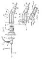
- FIG. 1 bis an enlarged fragmentary partially exploded perspective view of the distal end of the endoscopic instrument specifically illustrating the arrangement of the image sensor with respect to the other elements of the tubular portion of the endoscope;
- FIG. 2 ais a fragmentary cross-sectional view of a second embodiment of this invention illustrating another generic endoscope wherein the imaging device is incorporated in its entirety at the distal tip of the endoscope;
- FIG. 2 bis an enlarged fragmentary partially exploded perspective view of the distal end of the endoscope of FIG. 2 a illustrating the imaging device;
- FIG. 3 ais an elevational fragmentary cross-sectional view of the image sensor incorporated with a standard camera housing for connection to a rod lens endoscope;
- FIG. 3 bis a fragmentary cross-sectional view of the imaging device incorporated within the camera housing of FIG. 3 a;
- FIG. 3 cis a fragmentary cross-sectional view similar to that of FIG. 3 b illustrating a battery as an alternate source of power;
- FIG. 4is a schematic diagram of the functional electronic components which make up the imaging device
- FIG. 4 ais an enlarged schematic diagram of a circuit board which may include the array of pixels and the timing and control circuitry;
- FIG. 4 bis an enlarged schematic diagram of a video processing board having placed thereon the processing circuitry which processes the pre-video signal generated by the array of pixels and which converts the pre-video signal to a post-video signal which may be accepted by a standard video device;
- FIGS. 5 a – 5 eare schematic diagrams that illustrate an example of specific circuitry which may be used to make the imaging device.
- FIG. 6is a simplified schematic diagram of a passive pixel which may be placed in an array of passive pixels compatible with an imager of CMOS type construction;
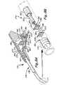
- FIG. 7 aillustrates another preferred embodiment including a fragmentary cross-sectional view of a generic endoscope wherein the handle of the endoscope houses processing circuitry of the imaging device;
- FIG. 7 bis an enlarged fragmentary partially exploded perspective view of the distal end of the endoscope specifically illustrating the arrangement of the image sensor with respect to the other elements of the tubular portion of the endoscope;
- FIG. 8 ais another fragmentary cross-sectional view of the generic endoscope of FIG. 7 a , but showing only one processing circuitry element within the handle of the endoscope;
- FIG. 8 bis an enlarged fragmentary partially exploded perspective view of the distal end of the endoscope of FIG. 8 a specifically illustrating the array of pixels being placed on one planar structure, and the timing and control circuitry being placed on another planar structure adjacent to the pixel array;
- FIG. 9is a graphical representation of how variable charge integration periods can enhance the capability to observe light or fluorescence from a viewed area.
- FIG. 10is a schematic diagram illustrating incorporation of variable charge integration capability with the imaging device of the invention.
- an endoscope 10which incorporates a reduced area imaging device 11 , shown in FIG. 1 b .
- the elements of the imaging devicemay all be found at one location or the elements may be separated from one another and interconnected by the appropriate cable(s).
- the array of pixels making up the image sensorcaptures images and stores them in the form of electrical energy by conversion of light photons to electrons. This conversion takes place by the photo diodes in each pixel which communicate with one or more capacitors which store the electrons.
- the structure of the endoscope 10includes a flexible or rigid tubular portion 14 which is inserted into the body of the patient and is placed at the appropriate location for viewing a desired surgical area.
- the tubular portion 14attaches at its proximal end to a handle portion 12 which may be grasped by a surgeon who is conducting the endoscopic procedure.
- the handle 12may include a central lumen or channel 13 which receives therethrough one or more cables or other structures which extend to the distal end 16 of tubular portion 14 .
- Handle portion 12may further include a supplementary channel 15 which intersects with central channel 13 and which may provide another point of entry for other cables, fluids or operative instruments to be placed through the endoscope.
- FIG. 1 billustrates the distal end of the endoscope 16 .
- the distal end 16may be characterized by an outer tube 18 which traverses the length of the tubular portion 14 and connects to the handle portion 12 .
- Placed concentrically within the outer tube 18may be one or more inner tubes 20 .
- the gap between inner tube 20 and outer tube 18forms a space in which one or more light fibers 22 or control wires 24 may be placed.
- a plurality of circumferentially spaced light fibers as illustrated in FIG. 1 bcan be used to illuminate the surgical site.
- control wires 24may communicate with a control mechanism (not shown) integrated on the handle portion 12 for manipulating the distal end 16 of the endoscope in a desired direction.
- the flexible tubular portion 14 coupled with a steerable featureenables the endoscope to be placed within winding bodily passages or other locations difficult to reach within the body.
- An image sensor 40may be placed within the central channel defined by inner tube 20 .
- a cable 26is used to house the conductors which communicate with the image sensor 40 .
- An intermediate support tube 28may be placed concentrically outside of cable 26 and concentrically within inner tube 20 to provide the necessary support for the cable 26 as it traverses through the inner channel defined by inner tube 20 .
- other well-known meansmay be provided to stabilize the cable 26 such as clips or other fastening means which may attach to the inner concentric surface of inner tube 20 .
- a control box 30may be placed remote from the endoscope 10 .
- the control box 30contains some of the processing circuitry which is used to process the image signal produced by image sensor 40 . Therefore, the imaging device 11 as previously defined would include the processing circuitry within control box 30 and the image sensor 40 located at the distal tip of the endoscope.
- Control box 30communicates with image sensor 40 by means of cable 32 which may simply be an insulated and shielded cable which houses therein cable 26 . Cable 32 is stabilized with respect to the handle portion 12 by means of a fitting 34 which ensures that cable 32 cannot be inadvertently pushed or pulled within channel 13 . Additionally, an additional fitting 35 may be provided to stabilize the entry of a light cable 36 which houses the plurality of light fibers 22 .
- Image sensor 40is illustrated as being a planar and square shaped member. However, the image sensor may be modified to be in a planar and circular shape to better fit within the channel defined by inner tube 20 . Accordingly, FIG. 1 b further shows an alternate shaped image sensor 40 ′ which is round.
- a lens group or system 42may be incorporated at the distal end of the endoscope in order to manipulate the image prior to it being impinged upon the array of pixels on the image sensor 40 . This lens system 42 may be sealed at the distal end 16 of the endoscope so that the tubular portion 14 is impervious to fluids entering through the distal end 16 . In the configuration of the imaging device 11 in FIGS.
- cable 26may simply be a three-conductor 50 ohm cable.
- Image sensor 40can be as small as 1 mm in its largest dimension. However, a more preferable size for most endoscopic procedures would dictate that the image sensor 40 be between 4 mm to 8 mm in its largest dimension.
- the image signal transmitted from the image sensor through conductor 48is also herein referred to as a pre-video signal. Once the pre-video signal has been transmitted from image sensor 40 by means of conductor 48 , it is received by video processing board 50 . Video processing board 50 then carries out all the necessary conditioning of the pre-video signal and places it in a form so that it may be viewed directly on a standard video device, television or standard computer video monitor.
- the signal produced by the video processing board 50can be further defined as a post-video signal which can be accepted by a standard video device. As shown in FIG.
- a conductor 49is provided which transmits the post-video signal to an output connector 58 on the exterior surface of control box 30 .
- the cable (not shown) extending from the desired video device (not shown)may receive the post-video signal by means of connector 58 .
- Power supply board 52may convert incoming power received through power source 54 into the desired voltage. In the preferred imager incorporated in this invention, the power to the imaging device is simply a direct current which can be a 1.5 volt to a 12 volt source. Incoming power from, for example, a wall receptacle, communicates with power supply board 52 by connector 56 . Power supply board 52 takes the incoming power source and regulates it to the desired level. Additionally, ground 46 is also shown as extending back to the source of power through connector 56 .
- FIG. 2 aillustrates a second embodiment of this invention wherein the imaging device is self-contained entirely within the distal end 16 of the endoscope, and a power source which drives the circuitry within the imaging device may come from a battery 66 housed within handle portion 12 .
- the video processing board 50may be placed directly behind image sensor 40 .
- a plurality of pin connectors 62serve to electrically couple image sensor 40 with video processing board 50 depending upon the specific configuration of image sensor 40 , pin connectors 62 may be provided either for structural support only, or to provide a means by which image signals are transmitted between image sensor 40 and board 50 .
- one or more supplementary boards 60may be provided which further contain processing circuitry to process the image signal and present it in a form which may be directly received by a desired video device.
- the area which is occupied by image sensor 40may be defined as the profile area of the imaging device and which determines its critical dimensions.
- any imaging elements that are found on boards 50 or 60must be able to be placed on one or more circuit boards which are longitudinally aligned with image sensor 40 along longitudinal axis XX. If the profile area is not critical in terms of limiting the largest sized imaging element within the imaging device, then the additional circuit boards 50 and 60 which are normally placed in line with image sensor 40 can be aligned in an offset manner or may be larger than the profile area of image sensor 40 . In the configuration of FIG. 2 b , it is desirable that elements 40 , 50 and 60 be approximately the same size so that they may fit uniformly within the central channel of the endoscope. Additionally, image sensor 40 may be bonded to lens system 42 in order to provide further structural support to the imaging device 11 when mounted within the distal end 16 .
- an additional channel 64may be provided in order that a power supply cable 68 may communicate with battery 66 .
- battery 66may itself be mounted within a well 65 formed in handle portion 12 .
- Cable 68carries the conductor 44 and ground 46 .
- Cable 68may intersect with cable 33 within channel 13 , cables 68 and 33 extending then to the distal end 16 .
- Cable 33can be a single conductor cable which transmits the post-video signal to a desired video device. In other words, cable 33 may simply be an insulated and shielded housing for conductor 49 which carries the post-video signal.
- a batteryis an ideal power source in lieu of a conductor which would trail the endoscope. Accordingly, the endoscope is made more mobile and easier to handle by eliminating at least one of the trailing cables.
- FIG. 3 aillustrates yet another preferred embodiment of this invention, wherein the imaging device can be used in conjunction with a standard rod lens endoscope 70 .
- rod lens endoscope 70includes a lens train 72 which includes a plurality of highly precise lenses (not shown) which are able to transmit an image from the distal end of the endoscope, to a camera in line with the endoscope.
- the rod lens endoscopeis equipped with a light guide coupling post 74 .
- Light guide post 74connects to a source of light in the form of a cable 77 having a plurality of fiber optic strands (not shown) which communicate with a source of light (not shown).
- the most common arrangement of the rod lens endoscopealso includes a “C” or “V” mount connector 78 which attaches to the eyepiece 76 .
- the “C” or “V” mountattaches at its other end to a camera group 80 .
- the camera group 80houses one or more of the elements of the imaging device.
- the small size of the imaging deviceis not a critical concern since the imaging device is not being placed at the distal end of the endoscope.
- the incorporation of the imaging device in a housing which would normally hold a traditional camerastill provides an advantageous arrangement.
- the camera group 80may include a housing 82 which connects to a power/video cable 86 .
- FIG. 3 aillustrates an arrangement of the imaging device 11 wherein the image sensor 40 is placed by itself within the housing 82 and the processing circuitry of the imaging device can be positioned in a remote control box as shown in FIG. 1 a . Accordingly, only three conductors 44 , 46 and 48 are necessary for providing power to the image sensor 40 and for transmitting the pre-video signal to the control box.
- the entire imaging device 11may be incorporated within camera group 80 , each of the elements of the imaging device being placed in the stacked arrangement similar to FIG. 2 b .
- sizeis not as much of a concern in the embodiment of FIGS. 3 a and 3 b since the camera group housing 82 is much larger than the distal tip of the endoscope of FIGS. 1 a and 2 a.
- FIG. 3 calso illustrates the use of a battery 66 which provides source of power to the imaging device in either FIG. 3 a or 3 b .
- housing 82is altered to include a battery housing 69 which houses the battery 66 therein.
- Battery housing 69may include a very small diameter channel which may allow conductor 48 or 49 to communicate directly with the processing circuitry or video device, respectively.
- the embodiment in FIG. 1 amay incorporate the use of a battery 66 as the source of power.
- handle 12 in FIG. 1 amay be altered in the same way as housing 82 to allow a battery to be attached to the handle portion 12 .
- FIG. 4is a schematic diagram illustrating one way in which the imaging device 11 may be constructed.
- the image sensor 40may include the timing and control circuits on the same planar structure. Power is supplied to image sensor 40 by power supply board 52 .
- the connection between image sensor 40 and board 52may simply be a cable having two conductors therein, one for ground and another for transmitting the desired voltage. These are illustrated as conductors 44 and 46 .
- the output from image sensor 40 in the form of the pre-video signalis input to video processor board 50 by means of the conductor 48 .
- conductor 48may simply be a 50 ohm conductor.
- Power and groundalso are supplied to video processing board 50 by conductors 44 and 46 from power supply board 52 .
- the output signal from the video processor board 50is in the form of the post-video signal and which may be carried by conductor 49 which can also be a 50 ohm conductor.
- cable 32can be used to house conductors 44 , 46 and 48 .
- cable 33can be used to house conductor 49 by itself when a battery power source is used, or alternatively, cable 33 may house conductors 44 , 46 and 49 if the embodiment of FIG. 2 a utilizes a power source from board 52 .
- a supplementary processing board 60may be provided to further enhance the pre-video signal.
- the supplementary board 60may be placed such that the pre-video signal from image sensor 40 is first sent to the supplementary board and then output to the video processor board 50 .
- the output from board 50can be carried along conductor 51 .
- This outputcan be defined as an enhanced pre-video signal.
- the post-video signal from video processor board 50may return to the supplementary board 60 for further processing, as further discussed below.
- the conductor used to transmit the post-video signal back to the supplementary boardis shown as conductor 59 .
- the power supply board 52may also provide power to the supplementary board in the same manner as to image sensor 40 and board 50 .
- image sensor 40may be placed remotely from boards 50 and 60 .
- image sensor 40 , and boards 50 and 60each may be placed within the distal end of the endoscope.
- FIG. 4illustrates the image sensor and the timing and control circuits being placed on the same planar structure
- the advantage in placing the timing and control circuits on the same planar structure as the image sensoris that only three connections are required between image sensor 40 and the rest of the imaging device, namely, conductors 44 , 46 and 48 . Additionally, placing the timing and control circuits on the same planar structure with the pixel array results in the pre-video signal having less noise. Furthermore, the addition of the timing and control circuits to the same planar structure carrying the image sensor only adds a negligible amount of size to one dimension of the planar structure.
- the pixel arrayis to be the only element on the planar structure, then additional connections must be made between the planar structure and the video processing board 50 in order to transmit the clock signals and other control signals to the pixel array.
- additional connectionsFor example, a ribbon-type cable (not shown) or a plurality of 50 ohm coaxial cables (not shown) must be used in order to control the downloading of information from the pixel array.
- a ribbon-type cable(not shown) or a plurality of 50 ohm coaxial cables (not shown) must be used in order to control the downloading of information from the pixel array.
- Each of these additional connectionswould be hard wired between the boards.
- FIG. 4 ais a more detailed schematic diagram of image sensor 40 which contains an array of pixels 90 and the timing and control circuits 92 .
- a pixel array 90which can be used within the invention is similar to that which is disclosed in U.S. Pat. No. 5,471,515 to Fossum, et al., said patent being incorporated by reference herein.
- FIG. 3 of Fossum, et al.illustrates the circuitry which makes up each pixel in the array of pixels 90 .
- the array of pixels 90 as described in Fossum, et al.is an active pixel group with intra-pixel charged transfer.
- the image sensor made by the array of pixelsis formed as a monolithic complementary metal oxide semiconductor integrated circuit which may be manufactured in an industry standard complementary metal oxide semiconductor process.
- the integrated circuitincludes a focal plane array of pixel cells, each one of the cells including a photo gate overlying the substrate for accumulating the photo generated charges.
- an imageimpinges upon the array of pixels, the image being in the form of photons which strike the photo diodes in the array of pixels.
- the photo diodes or photo detectorsconvert the photons into electrical energy or electrons which are stored in capacitors found in each pixel circuit.
- Each pixel circuithas its own amplifier which is controlled by the timing and control circuitry discussed below.
- the information or electrons stored in the capacitorsis unloaded in the desired sequence and at a desired frequency, and then sent to the video processing board 50 for further processing.
- the timing and control circuits 92are used to control the release of the image information or image signal stored in the pixel array.
- the pixelsare arranged in a plurality of rows and columns.
- the image information from each of the pixelsis first consolidated in a row by row fashion, and is then downloaded from one or more columns which contain the consolidated information from the rows.
- the control of information consolidated from the rowsis achieved by latches 94 , counter 96 , and decoder 98 .
- the operation of the latches, counter and decoderis similar to the operation of similar control circuitry found in other imaging devices.
- a latchis a means of controlling the flow of electrons from each individual addressed pixel in the array of pixels.
- a latch 94When a latch 94 is enabled, it will allow the transfer of electrons to the decoder 98 .
- the counter 96is programmed to count a discrete amount of information based upon a clock input from the timing and control circuits 92 .
- the image informationis allowed to pass through the latches 94 and be sent to the decoder 98 which places the consolidated information in a serial format.
- the row driver 100accounts for the serial information from each row and enables each row to be downloaded by the column or columns.
- the latches 94will initially allow the information stored in each pixel to be accessed.
- the counter 96then controls the amount of information flow based upon a desired time sequence. Once the counter has reached its set point, the decoder 98 then knows to take the information and place it in the serial format. The whole process is repeated, based upon the timing sequence that is programmed.
- the row driver 100When the row driver 100 has accounted for each of the rows, the row driver reads out each of the rows at the desired video rate.
- the information released from the column or columnsis also controlled by a series of latches 102 , a counter 104 and a decoder 106 .
- the column informationis also placed in a serial format which may then be sent to the video processing board 50 .
- This serial format of column informationis the pre-video signal carried by conductor 48 .
- the column signal conditioner 108places the column serial information in a manageable format in the form of desired voltage levels. In other words, the column signal conditioner 108 only accepts desired voltages from the downloaded column(s).
- the clock input to the timing and control circuits 92may simply be a quartz crystal timer. This clock input is divided into many other frequencies for use by the various counters.
- the run input to the timing and control circuit 92may simply be an on/off control.
- the default inputcan allow one to input the pre-video signal to a video processor board which may run at a frequency of other than 30 hertz.
- the data inputcontrols functions such as zoom. At least for a CMOS type active pixel array which can be accessed in a random manner, features such as zoom are easily manipulated by addressing only those pixels which locate a desired area of interest by the surgeon.
- image sensor 40Once image sensor 40 has created the pre-video signal, it is sent to the video processing board 50 for further processing.
- the pre-video signalis passed through a series of filters.
- One common filter arrangementmay include two low pass filters 114 and 116 , and a band pass filter 112 .
- the band pass filteronly passes low frequency components of the signal. Once these low frequency components pass, they are then sent to detector 120 and white balance circuit 124 , the white balance circuit distinguishing between the colors of red and blue.
- the white balance circuithelps the imaging device set its normal, which is white.
- the portion of the signal passing through low pass filter 114then travels through gain control 118 which reduces the magnitude or amplitude of this portion to a manageable level.
- the output from gain control 118is then fed back to the white balance circuit 124 .
- the portion of the signal traveling through filter 116is placed through the processor 122 .
- the portion of the signal carrying the luminance or non-chromais separated and sent to the Y chroma mixer 132 . Any chroma portion of the signal is held in processor 122 .
- this chroma portion of the signalis sent to a delay line 126 where the signal is then further reduced by switch 128 .
- the output of switch 128is sent through a balanced modulator 130 and also to the Y chroma mixer 132 where the processed chroma portion of the signal is mixed with the processed non-chroma portion.
- the output from the Y chroma mixer 132is sent to the NTSC/PAL encoder 134 , commonly known in the art as a “composite” encoder.
- the composite frequenciesare added to the signal leaving the Y chroma mixer 132 in encoder 134 to produce the post-video signal which may be accepted by a television.
- supplementary board 60which may be used to digitally enhance or otherwise further condition the pre-video signal produced from image sensor 40 .
- digital enhancementcan brighten or otherwise clarify the edges of an image viewed on a video screen. Additionally, the background images may be removed thus leaving only the foreground images or vice versa.
- the connection between image sensor 40 and board 60may simply be the conductor 48 which may also transfer the pre-video signal to board 50 .
- the pre-video signalOnce the pre-video signal has been digitally enhanced on supplementary board 60 , it is then sent to the video processor board 50 by means of another conductor 51 .
- the pre-video signalis an analog signal.
- the digitally enhanced pre-video signalmay either be a digital signal or it may be converted back to the analog domain prior to being sent to board 50 .
- supplementary board 60may further include other circuitry which may further condition the post-video signal so that it may be viewed in a desired format other than NTSC/PAL.
- intermediate conductor 59may transmit the signal output from Y chroma mixer 132 back to the supplementary board 60 where the signal is further encoded for viewing in a particular format.
- One common encoder which can be usedincludes an RGB encoder 154 .
- the RGB encoderseparates the signal into three separate colors (red, green and blue) so that the surgeon may selectively choose to view only those images containing one or more of the colors. Particularly in tissue analysis where dyes are used to color the tissue, the RGB encoder may help the surgeon to identify targeted tissue.
- the next encoder illustrated in FIG. 4is a SVHS encoder 156 (super video home system). This encoder splits or separates the luminance portion of the signal and the chroma portion of the signal prior to entering the video device. Some observers believe that a cleaner signal is input to the video device by such a separation which in turn results in a more clear video image viewed on the video device.
- the last encoder illustrated in FIG. 4is a VGA encoder 158 which enables the signal to be viewed on a standard VGA monitor which is common to many computer monitors.
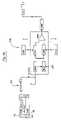
- FIGS. 5 a – 5 eillustrate in more detail one example of circuitry which may be used in the video processing board 50 in order to produce a post-video signal which may be directly accepted by a video device such as a television.
- the circuitry disclosed in FIGS. 5 a – 5 eis very similar to circuitry which is found in a miniature quarter-inch Panasonic camera, Model KS-162. It will be understood by those skilled in the art that the particular arrangement of elements found in FIGS. 5 a – 5 e are only exemplary of the type of video processing circuitry which may be incorporated in order to take the pre-video signal and condition it to be received by a desired video device.
- 5 volt poweris provided along with a ground by conductors 44 and 46 to board 50 .
- the pre-video signal carried by conductor 48is buffered at buffer 137 and then is transferred to amplifying group 138 .
- Amplifying group 138amplifies the signal to a usable level as well as achieving impedance matching for the remaining circuitry.
- the next major elementis the automatic gain control 140 shown in FIG. 5 b .
- Automatic gain control 140automatically controls the signal from amplifying group 138 to an acceptable level and also adds other characteristics to the signal as discussed below. More specifically, automatic gain control 140 conditions the signal based upon inputs from a 12 channel digital to analog converter 141 .
- Converter 141retrieves stored information from EEPROM (electrically erasable programmable read only memory) 143 .
- EEPROM 143is a non-volatile memory element which may store user information, for example, settings for color, tint, balance and the like.
- automatic gain control 140changes the texture or visual characteristics based upon user inputs.
- the signal leaving the automatic gain control 140is an analog signal until being converted by analog to digital converter 142 .
- Digital signal processor 144 of FIG. 5 cfurther processes the converted signal into a serial type digital signal.
- One function of the microprocessor 146is to control the manner in which digital signal processor 144 sorts the digital signals emanating from converter 142 .
- Microprocessor 146also controls analog to digital converter 142 in terms of when it is activated, when it accepts data, when to release data, and the rate at which data should be released.
- Microprocessor 146may also control other functions of the imaging device such as white balance.
- the microprocessor 146may selectively receive the information stored in the EEPROM 143 and carry out its various commands to further control the other elements within the circuitry.
- digital encoder 148After the signal is processed by digital signal processor 144 , the signal is sent to digital encoder 148 illustrated in FIG. 5 d . Some of the more important functions of digital encoder 148 are to encode the digital signal with synchronization, modulated chroma, blanking, horizontal drive, and the other components necessary so that the signal may be placed in a condition for reception by a video device such as a television monitor. As also illustrated in FIG. 5 d , once the signal has passed through digital encoder 148 , the signal is reconverted into an analog signal through digital to analog converter 150 .
- This reconverted analog signalis then buffered at buffers 151 and then sent to amplifier group 152 of FIG. 5 e which amplifies the signal so that it is readily accepted by a desired video device.
- amplifier group 152 of FIG. 5 ewhich amplifies the signal so that it is readily accepted by a desired video device.
- one SVHS outletis provided at 160
- two composite or NTSC outletsare provided at 162 and 164 , respectively.
- FIG. 6illustrates a simplified schematic diagram of a passive pixel which may be incorporated directly into the read out circuitry of Fossum, et al. (see FIG. 3 , U.S. Pat. No. 5,471,515; read out circuit or correlated double sampling circuit 70 ). As shown in FIG. 3 , U.S. Pat. No. 5,471,515; read out circuit or correlated double sampling circuit 70 ). As shown in FIG. 3 , U.S. Pat. No. 5,471,515; read out circuit or correlated double sampling circuit 70 ). As shown in FIG.
- each passive pixel 160 in a passive pixel arraycomprises a photo diode 162 with a transistor 164 that passes the photoelectrically generated signal from photo diode 162 to a charge integration amplifier (not shown) outside the pixel array.
- the timing and control circuitryactivates the access transistor 164 .
- the photoelectrically generated signal from photo diode 162then transfers to the capacitance of the column bus 166 where the charge integration amplifier (not shown) at the end of the column bus 166 senses the resulting voltage.
- the column bus voltageresets the photo diode 162 , and the timing and control circuitry then places the access transistor 164 in an off condition.
- the pixel 160is then ready for another integration cycle.
- FIG. 6illustrates that the readout circuit 70 of Fossum, et al. is compatible with either the active or passive pixel arrays disclosed herein.
- a manufacturer who has developed a passive pixel array with performance nearly equal to that of known active pixel devices and compatible with the read out circuitry of Fossum, et al.is VLSI Vision Ltd., 1190 Saratoga Avenue, Suite 180, San Jose, Calif. 95129.
- FIGS. 7 a and 7 billustrate yet another preferred embodiment of this invention.
- This embodimentalso incorporates a generic endoscope, such as shown in FIGS 1 a and 2 a .
- the generic endoscope 170includes a handle 172 which may be grasped by the surgeon.
- the handle 172has an interior opening 173 which allows wiring to pass through to the distal tip 177 of the endoscope.
- This interior opening 173also houses the processing circuitry of the imaging device.
- the generic endoscopefurther includes a tubular portion 174 which is placed within the patient's body and which is defined by a flexible outer tube 178 .
- a battery channel 175may also be incorporated within the handle 172 to receive a battery 176 .
- a lens system 180may be used to manipulate an image. Images are received upon a planar structure in the form of an image sensor 182 which includes an array of pixels and corresponding timing and control circuitry. This planar structure is the same as that illustrated in FIG. 4 a . Image sensor 182 incorporating the pixel array and timing and control circuitry produces a pre-video signal (either analog or digital) which is transmitted by pre-video out conductor 188 . A 5-volt power source and a ground are provided to image sensor 182 by conductors 184 and 186 , respectively.
- a protective cable or sheathing 190houses conductors 184 , 186 and 188 as they extend proximally back toward the handle 172 of the endoscope 170 . Additionally, a support tube 192 may fit over the protective cable 190 to provide further protection for the conductors.
- desired processing circuitrycan be placed directly within the handle of the endoscope since the processing circuitry is such a small size.
- the processing circuitry incorporated within the handle 172includes two planar structures, namely, a supplementary board 194 and a video processor board 196 . In terms of the construction of these boards, the boards 194 and 196 are the same as video processor board 50 and supplementary board 60 , respectively, of the first embodiment.
- Boards 194 and 196may also be spaced apart from one another and placed in an aligned position as by pin connectors 195 .
- Pin connectors 195are also of the same type as pin connectors 62 shown in FIG. 2 b .
- the pre-video signal transmitted by conductor 188is processed by the processing circuitry within the handle, and a post-video out signal is produced and transmitted by post-video out conductor 198 .
- Conductor 198then connects directly to the desired video device (not shown) such as a video screen or personal computer.
- the desired video devicenot shown
- 5-volt power conductor 184 , ground conductor 186 , and post-video out conductor 198may be housed within cable 199 which connects to the video device and a source of power (not shown).
- a fitting 200may be used to stabilize cable 199 in its attachment to the handle 172 .
- a light fiber bundle 202may extend through the endoscope to provide light to the distal tip 177 .
- a cable 203would extend back to a source of light (not shown), and fitting 204 would be used to stabilize the connection of cable 203 to the handle 172 .
- FIG. 7 afurther illustrates a power and ground conductor 206 which extends from the battery compartment/channel 175 in order to provide an alternate source of power to the endoscope.
- FIG. 7 ahas been simplified to better illustrate the differences between it and the previous embodiments. Accordingly, the light fibers and control wires which may extend to the distal end 177 are not illustrated (corresponding to light fibers 22 and control wires 24 of the first embodiment).
- FIGS. 8 a and 8 billustrate another endoscope which differs from FIGS. 7 a and 7 b by modifications made to the arrangement of the imaging device.
- FIG. 8 aalso does not illustrate the use of an alternate power source; however, it shall be understood, of course, that this Figure could also utilize a battery source of power as shown in FIG. 7 a .
- FIGS. 8 a and 8 billustrate an imaging device wherein the array of pixels 208 and the timing and control circuitry 210 are on two separate planar structures placed back to back to one another in an aligned fashion.
- a multistrand conductor 212transmits image signals produced by the pixel array 208 , and also carries the timing and control signals to the pixel array allowing the image signals to be read or unloaded at the desired speed, frequency, and sequence.
- FIG. 8 aillustrates the use of video processor board 196 , and no supplementary board 194 . It shall be understood that, for both FIGS. 7 a and 8 a , the specific processing circuitry found within the interior opening 173 of the handle can include whatever type of processing circuitry as needed to create a post-video out signal which is readily acceptable by a video device without any further processing. Thus, FIG. 7 a could be used without supplementary board 194 , and FIG. 8 a could incorporate the use of supplementary board 194 .
- boards 194 and 196have been greatly enlarged to better show their spatial arrangement and detail within interior opening 173 . Although it is possible that these boards may be of such illustrated size, as mentioned above with respect to the previous embodiment and boards 50 and 60 , these boards can be made small enough that the opening 173 within the endoscope has ample room to house the processing circuitry therein. In terms of the actual structure which is used to support the processing circuitry within the handle, the handle may be equipped with any suitable non-conductive support flanges or other extensions within the interior opening 173 which would allow the processing circuitry to be mounted thereon. Because of the extremely small size and insignificant weight of the processing circuitry, such supporting structure within interior opening 173 would be minimal.
- the intensity or brightness of an imagemay be enhanced by a CMOS-CID imager which has a variable charge integration capability.
- the example at FIG. 9shows a situation in which a viewed area may only reflect or emit an amount of light which is not normally capable of being seen by the human eye through a fluorescence microscope, endoscope, or may otherwise be very difficult to find.
- the image produced by the CMOS-CID imaging deviceintensifies the brightness or intensity of the image over the integration period to a much more readily observable amount of light.
- the brightness of a particular imageis measured on the vertical axis, while the time in which the image is viewed or observed is measured on the horizontal axis.
- a threshold level of observable light or fluorescenceis shown at horizontal line 304 , and which represents an average amount of light or fluorescence which can be observed by a currently available fluorescence microscope or endoscope without the aid of any special equipment. Any level of light or fluorescence falling below this threshold level 304 would be considered very difficult to observe.
- Dashed line 306represents the level of light or fluorescence which may be observed in viewing a particular area without the aid of an imager having variable charge integration capability.
- an imager having charge integration capabilitycould be used to enhance or brighten the observable light or fluorescence.
- the observed light or fluorescence using such an imageris depicted as line 308 . As shown, a three-second integration period has been chosen.
- the observed light or fluorescence 308is now above the threshold level 304 which makes the area under investigation much more easy to locate and view.
- the imageis further brightened or enhanced due to the continuing charge integration period wherein charge continues to accumulate in the pixels of the imager.
- the stepped pattern of observed light or fluorescence 308is due to the monitor update cycle or period.
- a first update of the monitor periodoccurs which reflects the increased charge accumulating in the pixels of the imager. Charge accumulates in the pixels in a linear fashion.
- the monitor update periodcould be reduced to show a more linear increase of brightness of observed fluorescence.
- the charge integration periodends, the accumulated charge is then released or dumped from the pixels, and a new charge integration period begins.
- FIG. 9shows the brightness of an image being repeated in a similar pattern between three and six seconds. It can be seen that the capability to view observed light or fluorescence is greatly enhanced by use of an imager having variable charge integration capability which may overcome low light conditions or low fluorescence of a particular bodily tissue.
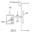
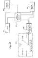
- FIG. 10is a schematic diagram of an imager and its processing circuitry which incorporate variable charge integration capability.
- Imager 40is coupled to its video processing circuitry 50 .
- Power supply 52supplies power to the imaging device and the additional circuitry to achieve charge integration.
- imager readout clock select circuitry 318is added which communicates with one or more of the video processor boards 50 .
- An imager integration time select switch 320is provided enabling an operator to manually select the desired integration period. As shown, the integration periods may be periods of less than one second, or more than one second.
- FIG. 10illustrates a situation in which an operator has chosen a three-second integration period. As the area is observed by the imager 40 , the imager will accumulate charge based upon the selected integration period. The image is viewed on the display monitor 316 . As also discussed above, the monitor update period can also be adjusted to provide more or less of a stepped brightness image. The operator would then adjust the charge integration period to obtain the most desirable image of the area being viewed.
- the imager 40may be used in conjunction with the optics of a fluorescence microscope. Many fluorescence microscopes today also have miniature cameras which are used to record images observed by the fluorescence microscope. Thus, the imager 40 could replace the miniature camera or imager used on commercially available fluorescence microscopes. Also, it shall be understood that an endoscope which may be used in fluorescence guided endoscopy may also incorporate variable charge integration capability in order to enhance the ability to find and evaluate fluorescing cells. Thus, the use of variable charge integration capability has multiple benefits not only in viewing cells which have been removed from a body, but also to view cells in the body which may undergo some treatment or surgical procedure, and are to be located by fluorescence guided endoscopy.
- Fluorescence-assisted surgery and fluorescence-assisted endoscopycan also be enhanced by providing an endoscope utilizing a CMOS-CID imager which has variable charge integration capability.
- the ability of a surgeon to view a cancerous growth inside the patientcan be enhanced by choosing an integration period which greatly expands the imaging sensitivity of the endoscope.
- the faint or slight amount of fluorescence which might not be observable through a CCD imagercan be enhanced by using a CMOS-CID imager modified with variable charge integration capability, resulting in readily observable fluorescence.
- use of an endoscope having a variable charge integration capabilityis advantageous for finding a cancerous growth.
- fluorescence guided endoscopymight be fluorescence endoscopy to find colon cancer.
- the surgeonwould conduct the endoscopic procedure looking for fluorescing colon tissue.
- the charge integration periodscould be adjusted to maximize observable fluorescence. In some cases, it may be very difficult for the surgeon to find all fluorescing tissues within the colon.
- the variable charge integration capability incorporated within the endoscopethe surgeon is more capable of finding each and every fluorescing groups of tissue within the colon to make a proper diagnosis.
- light delivery to the surgical sitecan be chosen from a desired frequency of light corresponding to the excitation frequency of the compound administered to the patient.
- an entire imaging devicemay be incorporated within the distal tip of an endoscope, or may have some elements of the imaging device being placed in a small remote box adjacent to the endoscope.
- the profile area of the imaging devicemay be made small enough to be placed into an endoscope which has a very small diameter tube.
- the imaging devicemay be placed into the channels of existing endoscopes to provide additional imaging capability without increasing the size of the endoscope.
- the imaging devicemay be powered by a standard power input connection in the form of a power cord, or a small lithium battery may be used.
- the imaging device of the inventioncan be further enhanced by incorporating a charge integration feature which enhances the ability of a user to selectively adjust the brightness of an image.
- a charge integration featurewhich enhances the ability of a user to selectively adjust the brightness of an image.
Landscapes
- Life Sciences & Earth Sciences (AREA)
- Health & Medical Sciences (AREA)
- Engineering & Computer Science (AREA)
- Surgery (AREA)
- Physics & Mathematics (AREA)
- Biomedical Technology (AREA)
- Public Health (AREA)
- Nuclear Medicine, Radiotherapy & Molecular Imaging (AREA)
- Optics & Photonics (AREA)
- Pathology (AREA)
- Radiology & Medical Imaging (AREA)
- Biophysics (AREA)
- Veterinary Medicine (AREA)
- Heart & Thoracic Surgery (AREA)
- Medical Informatics (AREA)
- Molecular Biology (AREA)
- Animal Behavior & Ethology (AREA)
- General Health & Medical Sciences (AREA)
- Signal Processing (AREA)
- Multimedia (AREA)
- Microelectronics & Electronic Packaging (AREA)
- Condensed Matter Physics & Semiconductors (AREA)
- General Physics & Mathematics (AREA)
- Computer Hardware Design (AREA)
- Power Engineering (AREA)
- Endoscopes (AREA)
- Studio Devices (AREA)
Abstract
Description
Claims (15)
Priority Applications (1)
| Application Number | Priority Date | Filing Date | Title |
|---|---|---|---|
| US09/971,749US6982740B2 (en) | 1997-11-24 | 2001-10-04 | Reduced area imaging devices utilizing selected charge integration periods |
Applications Claiming Priority (4)
| Application Number | Priority Date | Filing Date | Title |
|---|---|---|---|
| US08/976,976US5986693A (en) | 1997-10-06 | 1997-11-24 | Reduced area imaging devices incorporated within surgical instruments |
| US09/368,246US6310642B1 (en) | 1997-11-24 | 1999-08-03 | Reduced area imaging devices incorporated within surgical instruments |
| US09/586,768US6316215B1 (en) | 1999-12-27 | 2000-06-01 | Methods of cancer screening utilizing fluorescence detection techniques and selectable imager charge integration periods |
| US09/971,749US6982740B2 (en) | 1997-11-24 | 2001-10-04 | Reduced area imaging devices utilizing selected charge integration periods |
Related Parent Applications (1)
| Application Number | Title | Priority Date | Filing Date |
|---|---|---|---|
| US09/368,246Continuation-In-PartUS6310642B1 (en) | 1997-10-06 | 1999-08-03 | Reduced area imaging devices incorporated within surgical instruments |
Publications (2)
| Publication Number | Publication Date |
|---|---|
| US20020080248A1 US20020080248A1 (en) | 2002-06-27 |
| US6982740B2true US6982740B2 (en) | 2006-01-03 |
Family
ID=27408857
Family Applications (1)
| Application Number | Title | Priority Date | Filing Date |
|---|---|---|---|
| US09/971,749Expired - Fee RelatedUS6982740B2 (en) | 1997-11-24 | 2001-10-04 | Reduced area imaging devices utilizing selected charge integration periods |
Country Status (2)
| Country | Link |
|---|---|
| US (1) | US6982740B2 (en) |
| WO (1) | WO2003030525A1 (en) |
Cited By (146)
| Publication number | Priority date | Publication date | Assignee | Title |
|---|---|---|---|---|
| US20030220574A1 (en)* | 2002-03-18 | 2003-11-27 | Sarcos Investments Lc. | Miniaturized imaging device including utility aperture and SSID |
| US20030222325A1 (en)* | 2002-03-18 | 2003-12-04 | Sarcos Investments Lc. | Miniaturized imaging device with integrated circuit connector system |
| US20040199052A1 (en)* | 2003-04-01 | 2004-10-07 | Scimed Life Systems, Inc. | Endoscopic imaging system |
| US20050131279A1 (en)* | 2003-04-01 | 2005-06-16 | Boston Scientific Scimed, Inc. | Articulation joint for video endoscope |
| US20050159650A1 (en)* | 2003-12-18 | 2005-07-21 | Depuy Spine, Inc. | Surgical methods and surgical kits |
| US20050197536A1 (en)* | 2003-04-01 | 2005-09-08 | Banik Michael S. | Video endoscope |
| US20060069306A1 (en)* | 2004-09-30 | 2006-03-30 | Banik Michael S | Automated control of irrigation and aspiration in a single-use endoscope |
| US20060114986A1 (en)* | 2004-09-30 | 2006-06-01 | Knapp Keith N Ii | Adapter for use with digital imaging medical device |
| US20060146172A1 (en)* | 2002-03-18 | 2006-07-06 | Jacobsen Stephen C | Miniaturized utility device having integrated optical capabilities |
| US20070047947A1 (en)* | 2005-08-23 | 2007-03-01 | Instrument Technology Research Center | Close-up photograph device |
| US20070156026A1 (en)* | 2006-01-04 | 2007-07-05 | William Frasier | Surgical access devices and methods of minimally invasive surgery |
| US20070167828A1 (en)* | 2005-02-02 | 2007-07-19 | Vahid Saadat | Tissue imaging system variations |
| US20070249907A1 (en)* | 2006-04-20 | 2007-10-25 | Boulais Dennis R | Imaging assembly with transparent distal cap |
| US20080015445A1 (en)* | 2005-02-02 | 2008-01-17 | Voyage Medical, Inc. | Tissue visualization device and method variations |
| US20080015569A1 (en)* | 2005-02-02 | 2008-01-17 | Voyage Medical, Inc. | Methods and apparatus for treatment of atrial fibrillation |
| US20080033241A1 (en)* | 2006-08-01 | 2008-02-07 | Ruey-Feng Peh | Left atrial appendage closure |
| US20080030311A1 (en)* | 2006-01-20 | 2008-02-07 | Dayan Mervin A | System for monitoring an area adjacent a vehicle |
| US20080058591A1 (en)* | 2005-10-25 | 2008-03-06 | Voyage Medical, Inc. | Tissue visualization device and method variations |
| US20080058650A1 (en)* | 2006-09-01 | 2008-03-06 | Voyage Medical, Inc. | Coronary sinus cannulation |
| US20080183036A1 (en)* | 2006-12-18 | 2008-07-31 | Voyage Medical, Inc. | Systems and methods for unobstructed visualization and ablation |
| US20080259443A1 (en)* | 2007-04-20 | 2008-10-23 | Smith Barton A | Contact microscope using point source illumination |
| US20080275300A1 (en)* | 2007-04-27 | 2008-11-06 | Voyage Medical, Inc. | Complex shape steerable tissue visualization and manipulation catheter |
| US20080281293A1 (en)* | 2007-05-08 | 2008-11-13 | Voyage Medical, Inc. | Complex shape steerable tissue visualization and manipulation catheter |
| US20080304143A1 (en)* | 2007-06-05 | 2008-12-11 | Jacobsen Stephen C | Mini-scope for multi-directional imaging |
| US20090030276A1 (en)* | 2007-07-27 | 2009-01-29 | Voyage Medical, Inc. | Tissue visualization catheter with imaging systems integration |
| US20090030412A1 (en)* | 2007-05-11 | 2009-01-29 | Willis N Parker | Visual electrode ablation systems |
| US20090054803A1 (en)* | 2005-02-02 | 2009-02-26 | Vahid Saadat | Electrophysiology mapping and visualization system |
| US20090062790A1 (en)* | 2007-08-31 | 2009-03-05 | Voyage Medical, Inc. | Direct visualization bipolar ablation systems |
| US20090076498A1 (en)* | 2007-08-31 | 2009-03-19 | Voyage Medical, Inc. | Visualization and ablation system variations |
| US20090109283A1 (en)* | 2007-10-26 | 2009-04-30 | Joshua Lynn Scott | Integrated storage for industrial inspection handset |
| US20090125022A1 (en)* | 2007-11-12 | 2009-05-14 | Voyage Medical, Inc. | Tissue visualization and ablation systems |
| US20090143640A1 (en)* | 2007-11-26 | 2009-06-04 | Voyage Medical, Inc. | Combination imaging and treatment assemblies |
| US20090180197A1 (en)* | 2008-01-11 | 2009-07-16 | Sterling Lc | Grin lens microscope system |
| US20090203962A1 (en)* | 2008-02-07 | 2009-08-13 | Voyage Medical, Inc. | Stent delivery under direct visualization |
| US20090213212A1 (en)* | 2008-02-26 | 2009-08-27 | Kazuhiko Nakamura | Image pickup system and endoscope system |
| US20090221871A1 (en)* | 2006-09-01 | 2009-09-03 | Voyage Medical, Inc. | Precision control systems for tissue visualization and manipulation assemblies |
| US7597662B2 (en) | 2004-09-30 | 2009-10-06 | Boston Scientific Scimed, Inc. | Multi-fluid delivery system |
| US20090275842A1 (en)* | 2006-12-21 | 2009-11-05 | Vahid Saadat | Stabilization of visualization catheters |
| US20090287048A1 (en)* | 2008-05-16 | 2009-11-19 | Sterling Lc | Method and apparatus for imaging within a living body |
| US20090299363A1 (en)* | 2006-12-21 | 2009-12-03 | Vahid Saadat | Off-axis visualization systems |
| US20090326572A1 (en)* | 2008-06-27 | 2009-12-31 | Ruey-Feng Peh | Apparatus and methods for rapid tissue crossing |
| US20100004633A1 (en)* | 2008-07-07 | 2010-01-07 | Voyage Medical, Inc. | Catheter control systems |
| US20100004506A1 (en)* | 2005-02-02 | 2010-01-07 | Voyage Medical, Inc. | Tissue visualization and manipulation systems |
| US20100010311A1 (en)* | 2005-10-25 | 2010-01-14 | Voyage Medical, Inc. | Methods and apparatus for efficient purging |
| US20100130836A1 (en)* | 2008-11-14 | 2010-05-27 | Voyage Medical, Inc. | Image processing systems |
| US7758501B2 (en) | 2006-01-04 | 2010-07-20 | Depuy Spine, Inc. | Surgical reactors and methods of minimally invasive surgery |
| US20100188492A1 (en)* | 2008-07-30 | 2010-07-29 | Jacobsen Stephen C | Method And Device For Incremental Wavelength Variation To Analyze Tissue |
| US20100231703A1 (en)* | 2006-05-26 | 2010-09-16 | Varga Viktor Sebestyen | Method and system for digitizing a specimen with fluorescent target points |
| US20100256629A1 (en)* | 2009-04-06 | 2010-10-07 | Voyage Medical, Inc. | Methods and devices for treatment of the ostium |
| US20100256448A1 (en)* | 2003-04-01 | 2010-10-07 | Boston Scientific Scimed, Inc. | Fluid manifold for endoscope system |
| US20100261961A1 (en)* | 2006-12-21 | 2010-10-14 | Intuitive Surgical Operations, Inc. | Hermetically sealed distal sensor endoscope |
| US20100292558A1 (en)* | 2006-06-14 | 2010-11-18 | Voyage Medical, Inc. | In-vivo visualization systems |
| US7860555B2 (en) | 2005-02-02 | 2010-12-28 | Voyage Medical, Inc. | Tissue visualization and manipulation system |
| US20110037876A1 (en)* | 2009-08-13 | 2011-02-17 | Olive Medical Corp. | System, apparatus and methods for providing a single use imaging device for sterile environments |
| US20110050874A1 (en)* | 2009-09-03 | 2011-03-03 | Tower Semiconductor Ltd. | CMOS Image Sensor Pixel Without Internal Sample/Hold Circuit |
| US7918792B2 (en) | 2006-01-04 | 2011-04-05 | Depuy Spine, Inc. | Surgical retractor for use with minimally invasive spinal stabilization systems and methods of minimally invasive surgery |
| US7930016B1 (en) | 2005-02-02 | 2011-04-19 | Voyage Medical, Inc. | Tissue closure system |
| US20110130632A1 (en)* | 2009-11-30 | 2011-06-02 | King Systems Corporation | Visualization Instrument |
| US7955257B2 (en) | 2006-01-05 | 2011-06-07 | Depuy Spine, Inc. | Non-rigid surgical retractor |
| US20110137117A1 (en)* | 2002-03-18 | 2011-06-09 | Jacobsen Stephen C | Miniaturized Imaging Device Including GRIN Lens Optically Coupled to SSID |
| US20110238977A1 (en)* | 2010-03-25 | 2011-09-29 | Olive Medical Corporation | System and method for providing a single use imaging device for medical applications |
| US8078266B2 (en) | 2005-10-25 | 2011-12-13 | Voyage Medical, Inc. | Flow reduction hood systems |
| US8083671B2 (en) | 2004-09-30 | 2011-12-27 | Boston Scientific Scimed, Inc. | Fluid delivery system for use with an endoscope |
| US8118732B2 (en) | 2003-04-01 | 2012-02-21 | Boston Scientific Scimed, Inc. | Force feedback control system for video endoscope |
| US8137333B2 (en) | 2005-10-25 | 2012-03-20 | Voyage Medical, Inc. | Delivery of biological compounds to ischemic and/or infarcted tissue |
| CN102484677A (en)* | 2009-09-11 | 2012-05-30 | 奥林巴斯医疗株式会社 | Image pickup device and method for manufacturing image pickup device |
| US8202265B2 (en) | 2006-04-20 | 2012-06-19 | Boston Scientific Scimed, Inc. | Multiple lumen assembly for use in endoscopes or other medical devices |
| US20120197080A1 (en)* | 2011-02-01 | 2012-08-02 | Jin Murayama | Electronic endoscope system |
| US8333012B2 (en) | 2008-10-10 | 2012-12-18 | Voyage Medical, Inc. | Method of forming electrode placement and connection systems |
| US8460182B2 (en) | 2010-10-25 | 2013-06-11 | EndoSee Corporaton | Method and apparatus for hysteroscopy and endometrial biopsy |
| US8690887B2 (en) | 2010-02-08 | 2014-04-08 | Jeffrey B. Kleiner | Method and system for identification of a center of a vertebral disc space and corresponding central axis of a spinal column |
| US8690762B2 (en) | 2008-06-18 | 2014-04-08 | Raytheon Company | Transparent endoscope head defining a focal length |
| US8694071B2 (en) | 2010-02-12 | 2014-04-08 | Intuitive Surgical Operations, Inc. | Image stabilization techniques and methods |
| US8717428B2 (en) | 2009-10-01 | 2014-05-06 | Raytheon Company | Light diffusion apparatus |
| US8828028B2 (en) | 2009-11-03 | 2014-09-09 | Raytheon Company | Suture device and method for closing a planar opening |
| US8885034B2 (en) | 1997-10-06 | 2014-11-11 | Micro-Imaging Solutions Llc | Reduced area imaging device incorporated within endoscopic devices |
| US8926502B2 (en) | 2011-03-07 | 2015-01-06 | Endochoice, Inc. | Multi camera endoscope having a side service channel |
| US8952312B2 (en) | 2011-05-12 | 2015-02-10 | Olive Medical Corporation | Image sensor for endoscopic use |
| US9060704B2 (en) | 2008-11-04 | 2015-06-23 | Sarcos Lc | Method and device for wavelength shifted imaging |
| US9101287B2 (en) | 2011-03-07 | 2015-08-11 | Endochoice Innovation Center Ltd. | Multi camera endoscope assembly having multiple working channels |
| US9101268B2 (en) | 2009-06-18 | 2015-08-11 | Endochoice Innovation Center Ltd. | Multi-camera endoscope |
| US9101266B2 (en) | 2011-02-07 | 2015-08-11 | Endochoice Innovation Center Ltd. | Multi-element cover for a multi-camera endoscope |
| US9144664B2 (en) | 2009-10-01 | 2015-09-29 | Sarcos Lc | Method and apparatus for manipulating movement of a micro-catheter |
| US9307893B2 (en) | 2011-12-29 | 2016-04-12 | Cook Medical Technologies Llc | Space-optimized visualization catheter with camera train holder in a catheter with off-centered lumens |
| US9314147B2 (en) | 2011-12-13 | 2016-04-19 | Endochoice Innovation Center Ltd. | Rotatable connector for an endoscope |
| US9320419B2 (en) | 2010-12-09 | 2016-04-26 | Endochoice Innovation Center Ltd. | Fluid channeling component of a multi-camera endoscope |
| US9370295B2 (en) | 2014-01-13 | 2016-06-21 | Trice Medical, Inc. | Fully integrated, disposable tissue visualization device |
| US9402533B2 (en) | 2011-03-07 | 2016-08-02 | Endochoice Innovation Center Ltd. | Endoscope circuit board assembly |
| US9462234B2 (en) | 2012-07-26 | 2016-10-04 | DePuy Synthes Products, Inc. | Camera system with minimal area monolithic CMOS image sensor |
| US9492063B2 (en) | 2009-06-18 | 2016-11-15 | Endochoice Innovation Center Ltd. | Multi-viewing element endoscope |
| US9509917B2 (en) | 2012-07-26 | 2016-11-29 | DePuy Synthes Products, Inc. | Wide dynamic range using monochromatic sensor |
| US9516239B2 (en) | 2012-07-26 | 2016-12-06 | DePuy Synthes Products, Inc. | YCBCR pulsed illumination scheme in a light deficient environment |
| US9554692B2 (en) | 2009-06-18 | 2017-01-31 | EndoChoice Innovation Ctr. Ltd. | Multi-camera endoscope |
| US9560953B2 (en) | 2010-09-20 | 2017-02-07 | Endochoice, Inc. | Operational interface in a multi-viewing element endoscope |
| US9560954B2 (en) | 2012-07-24 | 2017-02-07 | Endochoice, Inc. | Connector for use with endoscope |
| US9641815B2 (en) | 2013-03-15 | 2017-05-02 | DePuy Synthes Products, Inc. | Super resolution and color motion artifact correction in a pulsed color imaging system |
| US9642513B2 (en) | 2009-06-18 | 2017-05-09 | Endochoice Inc. | Compact multi-viewing element endoscope system |
| US9655502B2 (en) | 2011-12-13 | 2017-05-23 | EndoChoice Innovation Center, Ltd. | Removable tip endoscope |
| US9661996B2 (en) | 2009-10-01 | 2017-05-30 | Sarcos Lc | Needle delivered imaging device |
| US9668643B2 (en) | 2011-12-29 | 2017-06-06 | Cook Medical Technologies Llc | Space-optimized visualization catheter with oblong shape |
| US9706903B2 (en) | 2009-06-18 | 2017-07-18 | Endochoice, Inc. | Multiple viewing elements endoscope system with modular imaging units |
| US9713417B2 (en) | 2009-06-18 | 2017-07-25 | Endochoice, Inc. | Image capture assembly for use in a multi-viewing elements endoscope |
| US9777913B2 (en) | 2013-03-15 | 2017-10-03 | DePuy Synthes Products, Inc. | Controlling the integral light energy of a laser pulse |
| US9808320B2 (en) | 2010-02-08 | 2017-11-07 | Jeffrey B. Kleiner | Method and system for identification of a center of a patient's body part |
| US9814522B2 (en) | 2010-04-06 | 2017-11-14 | Intuitive Surgical Operations, Inc. | Apparatus and methods for ablation efficacy |
| US9814374B2 (en) | 2010-12-09 | 2017-11-14 | Endochoice Innovation Center Ltd. | Flexible electronic circuit board for a multi-camera endoscope |
| US9820642B2 (en) | 2007-08-04 | 2017-11-21 | King Systems Corporation | Airway intubation device |
| US9872609B2 (en) | 2009-06-18 | 2018-01-23 | Endochoice Innovation Center Ltd. | Multi-camera endoscope |
| US9901244B2 (en) | 2009-06-18 | 2018-02-27 | Endochoice, Inc. | Circuit board assembly of a multiple viewing elements endoscope |
| US9986899B2 (en) | 2013-03-28 | 2018-06-05 | Endochoice, Inc. | Manifold for a multiple viewing elements endoscope |
| US9993142B2 (en) | 2013-03-28 | 2018-06-12 | Endochoice, Inc. | Fluid distribution device for a multiple viewing elements endoscope |
| US10045686B2 (en) | 2008-11-12 | 2018-08-14 | Trice Medical, Inc. | Tissue visualization and modification device |
| US10064540B2 (en) | 2005-02-02 | 2018-09-04 | Intuitive Surgical Operations, Inc. | Visualization apparatus for transseptal access |
| US10084944B2 (en) | 2014-03-21 | 2018-09-25 | DePuy Synthes Products, Inc. | Card edge connector for an imaging sensor |
| US10080486B2 (en) | 2010-09-20 | 2018-09-25 | Endochoice Innovation Center Ltd. | Multi-camera endoscope having fluid channels |
| US10111705B2 (en) | 2008-10-10 | 2018-10-30 | Intuitive Surgical Operations, Inc. | Integral electrode placement and connection systems |
| US10165929B2 (en) | 2009-06-18 | 2019-01-01 | Endochoice, Inc. | Compact multi-viewing element endoscope system |
| US10203493B2 (en) | 2010-10-28 | 2019-02-12 | Endochoice Innovation Center Ltd. | Optical systems for multi-sensor endoscopes |
| US10244927B2 (en) | 2011-12-29 | 2019-04-02 | Cook Medical Technologies Llc | Space-optimized visualization catheter with camera train holder |
| US10251530B2 (en) | 2013-03-15 | 2019-04-09 | DePuy Synthes Products, Inc. | Scope sensing in a light controlled environment |
| US10335131B2 (en) | 2006-10-23 | 2019-07-02 | Intuitive Surgical Operations, Inc. | Methods for preventing tissue migration |
| US10341593B2 (en) | 2013-03-15 | 2019-07-02 | DePuy Synthes Products, Inc. | Comprehensive fixed pattern noise cancellation |
| US10341588B2 (en) | 2013-03-15 | 2019-07-02 | DePuy Synthes Products, Inc. | Noise aware edge enhancement |
| US10342579B2 (en) | 2014-01-13 | 2019-07-09 | Trice Medical, Inc. | Fully integrated, disposable tissue visualization device |
| US10362926B2 (en) | 2012-06-25 | 2019-07-30 | Coopersurgical, Inc. | Low-cost instrument for endoscopically guided operative procedures |
| US10405886B2 (en) | 2015-08-11 | 2019-09-10 | Trice Medical, Inc. | Fully integrated, disposable tissue visualization device |
| US10499794B2 (en) | 2013-05-09 | 2019-12-10 | Endochoice, Inc. | Operational interface in a multi-viewing element endoscope |
| US10517469B2 (en) | 2013-03-15 | 2019-12-31 | DePuy Synthes Products, Inc. | Image sensor synchronization without input clock and data transmission clock |
| US10568496B2 (en) | 2012-07-26 | 2020-02-25 | DePuy Synthes Products, Inc. | Continuous video in a light deficient environment |
| US10702305B2 (en) | 2016-03-23 | 2020-07-07 | Coopersurgical, Inc. | Operative cannulas and related methods |
| US10750933B2 (en) | 2013-03-15 | 2020-08-25 | DePuy Synthes Products, Inc. | Minimize image sensor I/O and conductor counts in endoscope applications |
| US11096774B2 (en) | 2016-12-09 | 2021-08-24 | Zenflow, Inc. | Systems, devices, and methods for the accurate deployment of an implant in the prostatic urethra |
| US11278190B2 (en) | 2009-06-18 | 2022-03-22 | Endochoice, Inc. | Multi-viewing element endoscope |
| US11382496B2 (en) | 2006-12-21 | 2022-07-12 | Intuitive Surgical Operations, Inc. | Stereoscopic endoscope |
| US11478152B2 (en) | 2005-02-02 | 2022-10-25 | Intuitive Surgical Operations, Inc. | Electrophysiology mapping and visualization system |
| US11547446B2 (en) | 2014-01-13 | 2023-01-10 | Trice Medical, Inc. | Fully integrated, disposable tissue visualization device |
| US11547275B2 (en) | 2009-06-18 | 2023-01-10 | Endochoice, Inc. | Compact multi-viewing element endoscope system |
| US11622753B2 (en) | 2018-03-29 | 2023-04-11 | Trice Medical, Inc. | Fully integrated endoscope with biopsy capabilities and methods of use |
| US11771575B2 (en) | 2018-05-17 | 2023-10-03 | Zenflow, Inc. | Systems, devices, and methods for the accurate deployment and imaging of an implant in the prostatic urethra |
| US11864734B2 (en) | 2009-06-18 | 2024-01-09 | Endochoice, Inc. | Multi-camera endoscope |
| US11889986B2 (en) | 2010-12-09 | 2024-02-06 | Endochoice, Inc. | Flexible electronic circuit board for a multi-camera endoscope |
| US11890213B2 (en) | 2019-11-19 | 2024-02-06 | Zenflow, Inc. | Systems, devices, and methods for the accurate deployment and imaging of an implant in the prostatic urethra |
| US12035889B2 (en) | 2008-07-22 | 2024-07-16 | Trice Medical, Inc. | Tissue modification devices and methods of using the same |
| US12137873B2 (en) | 2009-06-18 | 2024-11-12 | Endochoice, Inc. | Compact multi-viewing element endoscope system |
| US12204087B2 (en) | 2010-10-28 | 2025-01-21 | Endochoice, Inc. | Optical systems for multi-sensor endoscopes |
| US12220105B2 (en) | 2010-06-16 | 2025-02-11 | Endochoice, Inc. | Circuit board assembly of a multiple viewing elements endoscope |
Families Citing this family (36)
| Publication number | Priority date | Publication date | Assignee | Title |
|---|---|---|---|---|
| US8599250B2 (en)* | 2002-03-12 | 2013-12-03 | Karl Storz Imaging, Inc. | Wireless camera coupling |
| US8723936B2 (en) | 2002-03-12 | 2014-05-13 | Karl Storz Imaging, Inc. | Wireless camera coupling with rotatable coupling |
| US9510740B2 (en) | 2002-03-12 | 2016-12-06 | Karl Storz Endovision, Inc. | Auto recognition of a shaver blade for medical use |
| US7223233B2 (en)* | 2002-08-02 | 2007-05-29 | Warsaw Orthopedic, Inc. | Systems and techniques for illuminating a surgical space |
| KR101008813B1 (en)* | 2002-08-02 | 2011-01-14 | 워쏘우 오르쏘페딕 인코포레이티드 | Surgery room lighting systems and technologies |
| US20040130781A1 (en)* | 2003-01-07 | 2004-07-08 | Katsuhiko Shinohara | Image-forming methods of an optical microscope and an optical telescope |
| TW581668B (en)* | 2003-10-15 | 2004-04-01 | Der-Yang Tien | Endoscopic device |
| CN100339042C (en)* | 2003-11-12 | 2007-09-26 | 奥林巴斯株式会社 | Endoscope |
| EP1799096A2 (en) | 2004-09-30 | 2007-06-27 | Boston Scientific Scimed, Inc. | System and method of obstruction removal |
| US7241263B2 (en) | 2004-09-30 | 2007-07-10 | Scimed Life Systems, Inc. | Selectively rotatable shaft coupler |
| JP2008514363A (en) | 2004-09-30 | 2008-05-08 | ボストン サイエンティフィック リミテッド | Multifunctional endoscope system for use in electrosurgical applications |
| CN100421613C (en)* | 2004-11-16 | 2008-10-01 | 医电科技股份有限公司 | Video Intubation Assist Device |
| DE102005000655A1 (en)* | 2005-01-04 | 2006-07-13 | Robert Bosch Gmbh | Image capture device |
| US8097003B2 (en) | 2005-05-13 | 2012-01-17 | Boston Scientific Scimed, Inc. | Endoscopic apparatus with integrated variceal ligation device |
| US7846107B2 (en) | 2005-05-13 | 2010-12-07 | Boston Scientific Scimed, Inc. | Endoscopic apparatus with integrated multiple biopsy device |
| US20060285339A1 (en)* | 2005-06-20 | 2006-12-21 | William Frasier | Adjustable light source holder |
| US8052597B2 (en) | 2005-08-30 | 2011-11-08 | Boston Scientific Scimed, Inc. | Method for forming an endoscope articulation joint |
| US20070100210A1 (en)* | 2005-11-02 | 2007-05-03 | Depuy Spine, Inc. | Illuminated surgical access system including a surgical access device and coupled light emitter |
| US7967759B2 (en) | 2006-01-19 | 2011-06-28 | Boston Scientific Scimed, Inc. | Endoscopic system with integrated patient respiratory status indicator |
| US8888684B2 (en) | 2006-03-27 | 2014-11-18 | Boston Scientific Scimed, Inc. | Medical devices with local drug delivery capabilities |
| US8430813B2 (en) | 2006-05-26 | 2013-04-30 | Depuy Spine, Inc. | Illuminated surgical access system including a surgical access device and integrated light emitter |
| US7976459B2 (en)* | 2006-10-17 | 2011-07-12 | Intra L.L.C. | Portable endoscope for intubation |
| EP2149067A1 (en)* | 2007-04-19 | 2010-02-03 | D.V.P. Technologies Ltd. | Imaging system and method for use in monitoring a field of regard |
| US20080287937A1 (en)* | 2007-05-15 | 2008-11-20 | Warsaw Orthopedic, Inc. | Surgical Instrument for Illuminating and Monitoring a Surgical Site |
| US8771177B2 (en) | 2008-07-08 | 2014-07-08 | Karl Storz Imaging, Inc. | Wide angle flexible endoscope |
| US8758234B2 (en) | 2008-07-08 | 2014-06-24 | Karl Storz Imaging, Inc. | Solid state variable direction of view endoscope |
| US10092169B2 (en) | 2008-07-08 | 2018-10-09 | Karl Storz Imaging, Inc. | Solid state variable direction of view endoscope |
| US20110009694A1 (en)* | 2009-07-10 | 2011-01-13 | Schultz Eric E | Hand-held minimally dimensioned diagnostic device having integrated distal end visualization |
| DE102010050227A1 (en)* | 2010-11-04 | 2012-05-10 | Siemens Aktiengesellschaft | Endoscope with 3D functionality |
| US9332193B2 (en) | 2011-11-14 | 2016-05-03 | Omnivision Technologies, Inc. | Synchronization of image acquisition in multiple image sensors with a synchronization clock signal |
| US9119544B2 (en)* | 2012-09-19 | 2015-09-01 | Omnivision Technologies, Inc. | Acquiring global shutter-type video images with CMOS pixel array by strobing light during vertical blanking period in otherwise dark environment |
| US8699868B1 (en) | 2013-03-14 | 2014-04-15 | Microsoft Corporation | Anti-shake correction system for curved optical sensor |
| US9498112B1 (en)* | 2013-03-15 | 2016-11-22 | Brent Stewart | Laryngoscope |
| JP6072389B1 (en)* | 2015-06-03 | 2017-02-01 | オリンパス株式会社 | Endoscope connector |
| JP7017846B2 (en) | 2016-04-25 | 2022-02-09 | パナソニックi-PROセンシングソリューションズ株式会社 | Endoscope |
| US11529038B2 (en)* | 2018-10-02 | 2022-12-20 | Elements Endoscopy, Inc. | Endoscope with inertial measurement units and / or haptic input controls |
Citations (32)
| Publication number | Priority date | Publication date | Assignee | Title |
|---|---|---|---|---|
| US4491865A (en) | 1982-09-29 | 1985-01-01 | Welch Allyn, Inc. | Image sensor assembly |
| US4745471A (en) | 1986-05-13 | 1988-05-17 | Olympus Optical Co., Ltd. | Solid-state imaging apparatus and endoscope |
| US4786965A (en) | 1986-09-04 | 1988-11-22 | Olympus Optical Co., Ltd. | Eletronic endoscope with an imaging device having side bonding pads |
| US4814648A (en) | 1987-09-24 | 1989-03-21 | Texas Instruments Incorporated | Low 1/f noise amplifier for CCD imagers |
| US4854302A (en) | 1987-11-12 | 1989-08-08 | Welch Allyn, Inc. | Video equipped endoscope with needle probe |
| US4869246A (en) | 1987-12-11 | 1989-09-26 | Adair Edwin Lloyd | Method for controllably embolyzing blood vessels |
| US4942473A (en) | 1987-07-16 | 1990-07-17 | Techninon Research & Development Foundation | Intelligent scan image sensor |
| USRE33854E (en) | 1989-02-03 | 1992-03-24 | sterilizable sheathpe with .[.heat.]. | |
| US5116317A (en) | 1988-06-16 | 1992-05-26 | Optimed Technologies, Inc. | Angioplasty catheter with integral fiber optic assembly |
| EP0492349A1 (en) | 1990-12-28 | 1992-07-01 | Matsushita Electric Industrial Co., Ltd. | Camera head for solid-state image pickup device and method of producing same |
| US5162913A (en) | 1990-02-26 | 1992-11-10 | Medical Concepts, Inc. | Apparatus for modulating the output of a ccd camera |
| US5220198A (en) | 1990-08-27 | 1993-06-15 | Olympus Optical Co., Ltd. | Solid state imaging apparatus in which a solid state imaging device chip and substrate are face-bonded with each other |
| US5251613A (en) | 1991-05-06 | 1993-10-12 | Adair Edwin Lloyd | Method of cervical videoscope with detachable camera |
| US5381784A (en) | 1992-09-30 | 1995-01-17 | Adair; Edwin L. | Stereoscopic endoscope |
| US5402768A (en) | 1992-09-01 | 1995-04-04 | Adair; Edwin L. | Endoscope with reusable core and disposable sheath with passageways |
| US5453785A (en) | 1992-04-30 | 1995-09-26 | Jos. Schneider Optische Werke Kreuznach Gmbh & Co. Kg | Measurement camera with fixed geometry and rigid length support |
| US5471515A (en) | 1994-01-28 | 1995-11-28 | California Institute Of Technology | Active pixel sensor with intra-pixel charge transfer |
| US5489256A (en) | 1992-09-01 | 1996-02-06 | Adair; Edwin L. | Sterilizable endoscope with separable disposable tube assembly |
| US5605531A (en) | 1994-04-08 | 1997-02-25 | Tilane Corporation | Apparatus for use with endoscopy and fluoroscopy for automatic switching between video modes |
| US5630783A (en) | 1995-08-11 | 1997-05-20 | Steinberg; Jeffrey | Portable cystoscope |
| US5630782A (en) | 1992-09-01 | 1997-05-20 | Adair; Edwin L. | Sterilizable endoscope with separable auxiliary assembly |
| US5682199A (en) | 1996-03-28 | 1997-10-28 | Jedmed Instrument Company | Video endoscope with interchangeable endoscope heads |
| US5701155A (en) | 1992-09-11 | 1997-12-23 | Welch Allyn, Inc. | Processor module for video inspection probe |
| US5734418A (en) | 1996-07-17 | 1998-03-31 | Welch Allyn, Inc. | Endoscope with tab imager package |
| US5754313A (en) | 1996-07-17 | 1998-05-19 | Welch Allyn, Inc. | Imager assembly |
| EP0932302A2 (en) | 1998-01-22 | 1999-07-28 | Eastman Kodak Company | A CMOS active pixel digital camera |
| US5980450A (en) | 1997-05-07 | 1999-11-09 | Pinotage, Llc | Coupling device for use in an imaging system |
| US6141037A (en)* | 1998-03-18 | 2000-10-31 | Linvatec Corporation | Video camera system and related method |
| US6232589B1 (en)* | 1999-01-19 | 2001-05-15 | Photon Vision Systems | Single polysilicon CMOS pixel with extended dynamic range |
| US6243131B1 (en)* | 1991-05-13 | 2001-06-05 | Interactive Pictures Corporation | Method for directly scanning a rectilinear imaging element using a non-linear scan |
| US6413209B1 (en) | 1995-09-15 | 2002-07-02 | Med Images, Inc. | Imaging system with condensation control |
| US6417882B1 (en)* | 1997-05-06 | 2002-07-09 | Texas Instruments Incorporated | CMOS sensor camera with on-chip image compression |
Family Cites Families (1)
| Publication number | Priority date | Publication date | Assignee | Title |
|---|---|---|---|---|
| US5929901A (en)* | 1997-10-06 | 1999-07-27 | Adair; Edwin L. | Reduced area imaging devices incorporated within surgical instruments |
- 2001
- 2001-10-04USUS09/971,749patent/US6982740B2/ennot_activeExpired - Fee Related
- 2001-11-21WOPCT/US2001/044069patent/WO2003030525A1/ennot_activeApplication Discontinuation
Patent Citations (32)
| Publication number | Priority date | Publication date | Assignee | Title |
|---|---|---|---|---|
| US4491865A (en) | 1982-09-29 | 1985-01-01 | Welch Allyn, Inc. | Image sensor assembly |
| US4745471A (en) | 1986-05-13 | 1988-05-17 | Olympus Optical Co., Ltd. | Solid-state imaging apparatus and endoscope |
| US4786965A (en) | 1986-09-04 | 1988-11-22 | Olympus Optical Co., Ltd. | Eletronic endoscope with an imaging device having side bonding pads |
| US4942473A (en) | 1987-07-16 | 1990-07-17 | Techninon Research & Development Foundation | Intelligent scan image sensor |
| US4814648A (en) | 1987-09-24 | 1989-03-21 | Texas Instruments Incorporated | Low 1/f noise amplifier for CCD imagers |
| US4854302A (en) | 1987-11-12 | 1989-08-08 | Welch Allyn, Inc. | Video equipped endoscope with needle probe |
| US4869246A (en) | 1987-12-11 | 1989-09-26 | Adair Edwin Lloyd | Method for controllably embolyzing blood vessels |
| US5116317A (en) | 1988-06-16 | 1992-05-26 | Optimed Technologies, Inc. | Angioplasty catheter with integral fiber optic assembly |
| USRE33854E (en) | 1989-02-03 | 1992-03-24 | sterilizable sheathpe with .[.heat.]. | |
| US5162913A (en) | 1990-02-26 | 1992-11-10 | Medical Concepts, Inc. | Apparatus for modulating the output of a ccd camera |
| US5220198A (en) | 1990-08-27 | 1993-06-15 | Olympus Optical Co., Ltd. | Solid state imaging apparatus in which a solid state imaging device chip and substrate are face-bonded with each other |
| EP0492349A1 (en) | 1990-12-28 | 1992-07-01 | Matsushita Electric Industrial Co., Ltd. | Camera head for solid-state image pickup device and method of producing same |
| US5251613A (en) | 1991-05-06 | 1993-10-12 | Adair Edwin Lloyd | Method of cervical videoscope with detachable camera |
| US6243131B1 (en)* | 1991-05-13 | 2001-06-05 | Interactive Pictures Corporation | Method for directly scanning a rectilinear imaging element using a non-linear scan |
| US5453785A (en) | 1992-04-30 | 1995-09-26 | Jos. Schneider Optische Werke Kreuznach Gmbh & Co. Kg | Measurement camera with fixed geometry and rigid length support |
| US5630782A (en) | 1992-09-01 | 1997-05-20 | Adair; Edwin L. | Sterilizable endoscope with separable auxiliary assembly |
| US5402768A (en) | 1992-09-01 | 1995-04-04 | Adair; Edwin L. | Endoscope with reusable core and disposable sheath with passageways |
| US5489256A (en) | 1992-09-01 | 1996-02-06 | Adair; Edwin L. | Sterilizable endoscope with separable disposable tube assembly |
| US5701155A (en) | 1992-09-11 | 1997-12-23 | Welch Allyn, Inc. | Processor module for video inspection probe |
| US5381784A (en) | 1992-09-30 | 1995-01-17 | Adair; Edwin L. | Stereoscopic endoscope |
| US5471515A (en) | 1994-01-28 | 1995-11-28 | California Institute Of Technology | Active pixel sensor with intra-pixel charge transfer |
| US5605531A (en) | 1994-04-08 | 1997-02-25 | Tilane Corporation | Apparatus for use with endoscopy and fluoroscopy for automatic switching between video modes |
| US5630783A (en) | 1995-08-11 | 1997-05-20 | Steinberg; Jeffrey | Portable cystoscope |
| US6413209B1 (en) | 1995-09-15 | 2002-07-02 | Med Images, Inc. | Imaging system with condensation control |
| US5682199A (en) | 1996-03-28 | 1997-10-28 | Jedmed Instrument Company | Video endoscope with interchangeable endoscope heads |
| US5734418A (en) | 1996-07-17 | 1998-03-31 | Welch Allyn, Inc. | Endoscope with tab imager package |
| US5754313A (en) | 1996-07-17 | 1998-05-19 | Welch Allyn, Inc. | Imager assembly |
| US6417882B1 (en)* | 1997-05-06 | 2002-07-09 | Texas Instruments Incorporated | CMOS sensor camera with on-chip image compression |
| US5980450A (en) | 1997-05-07 | 1999-11-09 | Pinotage, Llc | Coupling device for use in an imaging system |
| EP0932302A2 (en) | 1998-01-22 | 1999-07-28 | Eastman Kodak Company | A CMOS active pixel digital camera |
| US6141037A (en)* | 1998-03-18 | 2000-10-31 | Linvatec Corporation | Video camera system and related method |
| US6232589B1 (en)* | 1999-01-19 | 2001-05-15 | Photon Vision Systems | Single polysilicon CMOS pixel with extended dynamic range |
Non-Patent Citations (4)
| Title |
|---|
| "Active-Pixel Image Sensor Integrated with Readout Circuits"; NASA Tech Briefs, Oct. 1996. |
| "Applications Hold the Key to Imager Choice"; Photonics Spectra, Mar. 1997. |
| "Imaging Options Expand with CMOS Technology"; Laser Focus World, Jun. 1997. |
| "NASA's Tiny Camera Has a Wide-Angle Future"; Business Week, Mar. 6, 1995. |
Cited By (381)
| Publication number | Priority date | Publication date | Assignee | Title |
|---|---|---|---|---|
| US9667896B2 (en) | 1997-10-06 | 2017-05-30 | Cellect Llc | Reduced area imaging device incorporated within endoscopic devices |
| US8885034B2 (en) | 1997-10-06 | 2014-11-11 | Micro-Imaging Solutions Llc | Reduced area imaging device incorporated within endoscopic devices |
| US9186052B1 (en) | 1997-10-06 | 2015-11-17 | Micro-Imagaing Solutions | Reduced area imaging device incorporated within endoscopic devices |
| US9307895B2 (en) | 1997-10-06 | 2016-04-12 | Micro-Imaging Solutions, Llc | Reduced area imaging device incorporated within endoscopic devices |
| US9198565B2 (en) | 1997-10-06 | 2015-12-01 | Micro-Imaging Solutions | Reduced area imaging device incorporated within endoscopic devices |
| US7787939B2 (en) | 2002-03-18 | 2010-08-31 | Sterling Lc | Miniaturized imaging device including utility aperture and SSID |
| US20110137117A1 (en)* | 2002-03-18 | 2011-06-09 | Jacobsen Stephen C | Miniaturized Imaging Device Including GRIN Lens Optically Coupled to SSID |
| US7591780B2 (en) | 2002-03-18 | 2009-09-22 | Sterling Lc | Miniaturized imaging device with integrated circuit connector system |
| US7629659B2 (en) | 2002-03-18 | 2009-12-08 | Sterling Lc | Miniaturized imaging device with integrated circuit connector system |
| US20060146172A1 (en)* | 2002-03-18 | 2006-07-06 | Jacobsen Stephen C | Miniaturized utility device having integrated optical capabilities |
| US8614768B2 (en) | 2002-03-18 | 2013-12-24 | Raytheon Company | Miniaturized imaging device including GRIN lens optically coupled to SSID |
| US20080185672A1 (en)* | 2002-03-18 | 2008-08-07 | Jacobsen Stephen C | Miniaturized imaging device with integrated circuit connector system |
| US20030220574A1 (en)* | 2002-03-18 | 2003-11-27 | Sarcos Investments Lc. | Miniaturized imaging device including utility aperture and SSID |
| US20030222325A1 (en)* | 2002-03-18 | 2003-12-04 | Sarcos Investments Lc. | Miniaturized imaging device with integrated circuit connector system |
| US20100076266A1 (en)* | 2003-04-01 | 2010-03-25 | Boston Scientific Scimed, Inc | Articulation joint for video endoscope |
| US8608648B2 (en) | 2003-04-01 | 2013-12-17 | Boston Scientific Scimed, Inc. | Articulation joint |
| US20100048999A1 (en)* | 2003-04-01 | 2010-02-25 | Boston Scientific Scimed, Inc. | Video endoscope |
| US8425408B2 (en) | 2003-04-01 | 2013-04-23 | Boston Scientific Scimed, Inc. | Articulation joint for video endoscope |
| US8535219B2 (en) | 2003-04-01 | 2013-09-17 | Boston Scientific Scimed, Inc. | Fluid manifold for endoscope system |
| US8622894B2 (en) | 2003-04-01 | 2014-01-07 | Boston Scientific Scimed, Inc. | Articulation joint |
| US7578786B2 (en) | 2003-04-01 | 2009-08-25 | Boston Scientific Scimed, Inc. | Video endoscope |
| US9913573B2 (en) | 2003-04-01 | 2018-03-13 | Boston Scientific Scimed, Inc. | Endoscopic imaging system |
| US7413543B2 (en) | 2003-04-01 | 2008-08-19 | Scimed Life Systems, Inc. | Endoscope with actively cooled illumination sources |
| US8475366B2 (en) | 2003-04-01 | 2013-07-02 | Boston Scientific Scimed, Inc. | Articulation joint for a medical device |
| US8118732B2 (en) | 2003-04-01 | 2012-02-21 | Boston Scientific Scimed, Inc. | Force feedback control system for video endoscope |
| US7591783B2 (en) | 2003-04-01 | 2009-09-22 | Boston Scientific Scimed, Inc. | Articulation joint for video endoscope |
| US10765307B2 (en) | 2003-04-01 | 2020-09-08 | Boston Scientific Scimed, Inc. | Endoscopic imaging system |
| US20050197536A1 (en)* | 2003-04-01 | 2005-09-08 | Banik Michael S. | Video endoscope |
| US20100256448A1 (en)* | 2003-04-01 | 2010-10-07 | Boston Scientific Scimed, Inc. | Fluid manifold for endoscope system |
| US11324395B2 (en) | 2003-04-01 | 2022-05-10 | Boston Scientific Scimed, Inc. | Endoscopic imaging system |
| US20050131279A1 (en)* | 2003-04-01 | 2005-06-16 | Boston Scientific Scimed, Inc. | Articulation joint for video endoscope |
| US20050075538A1 (en)* | 2003-04-01 | 2005-04-07 | Banik Michael S. | Single use endoscopic imaging system |
| US20040199052A1 (en)* | 2003-04-01 | 2004-10-07 | Scimed Life Systems, Inc. | Endoscopic imaging system |
| US8602984B2 (en) | 2003-12-18 | 2013-12-10 | DePuy Synthes Products, LLC | Surgical retractor systems and illuminated cannulae |
| US10869657B2 (en) | 2003-12-18 | 2020-12-22 | DePuy Synthes Products, Inc. | Surgical retractor systems and illuminated cannulae |
| US20050159650A1 (en)* | 2003-12-18 | 2005-07-21 | Depuy Spine, Inc. | Surgical methods and surgical kits |
| US8622897B2 (en) | 2003-12-18 | 2014-01-07 | DePuy Synthes Products, LLC | Surgical methods and surgical kits |
| US20090018400A1 (en)* | 2003-12-18 | 2009-01-15 | Depuy Spine, Inc. | Surgical retractor systems and illuminated cannulae |
| US8038611B2 (en) | 2003-12-18 | 2011-10-18 | Depuy Spine, Inc. | Surgical methods and surgical kits |
| US8199187B2 (en) | 2004-09-30 | 2012-06-12 | Boston Scientific Scimed, Inc. | Adapter for use with digital imaging medical device |
| US8083671B2 (en) | 2004-09-30 | 2011-12-27 | Boston Scientific Scimed, Inc. | Fluid delivery system for use with an endoscope |
| US8435172B2 (en) | 2004-09-30 | 2013-05-07 | Boston Scientific Scimed, Inc. | Automated control of irrigation and aspiration in a single-use endoscope |
| US7479106B2 (en) | 2004-09-30 | 2009-01-20 | Boston Scientific Scimed, Inc. | Automated control of irrigation and aspiration in a single-use endoscope |
| US20060114986A1 (en)* | 2004-09-30 | 2006-06-01 | Knapp Keith N Ii | Adapter for use with digital imaging medical device |
| US20060069306A1 (en)* | 2004-09-30 | 2006-03-30 | Banik Michael S | Automated control of irrigation and aspiration in a single-use endoscope |
| US7597662B2 (en) | 2004-09-30 | 2009-10-06 | Boston Scientific Scimed, Inc. | Multi-fluid delivery system |
| USRE46007E1 (en) | 2004-09-30 | 2016-05-24 | Boston Scientific Scimed, Inc. | Automated control of irrigation and aspiration in a single-use endoscope |
| US10772492B2 (en) | 2005-02-02 | 2020-09-15 | Intuitive Surgical Operations, Inc. | Methods and apparatus for efficient purging |
| US20090054803A1 (en)* | 2005-02-02 | 2009-02-26 | Vahid Saadat | Electrophysiology mapping and visualization system |
| US10463237B2 (en) | 2005-02-02 | 2019-11-05 | Intuitive Surgical Operations, Inc. | Delivery of biological compounds to ischemic and/or infarcted tissue |
| US11478152B2 (en) | 2005-02-02 | 2022-10-25 | Intuitive Surgical Operations, Inc. | Electrophysiology mapping and visualization system |
| US8050746B2 (en) | 2005-02-02 | 2011-11-01 | Voyage Medical, Inc. | Tissue visualization device and method variations |
| US20100004506A1 (en)* | 2005-02-02 | 2010-01-07 | Voyage Medical, Inc. | Tissue visualization and manipulation systems |
| US10368729B2 (en) | 2005-02-02 | 2019-08-06 | Intuitive Surgical Operations, Inc. | Methods and apparatus for efficient purging |
| US20070167828A1 (en)* | 2005-02-02 | 2007-07-19 | Vahid Saadat | Tissue imaging system variations |
| US11406250B2 (en) | 2005-02-02 | 2022-08-09 | Intuitive Surgical Operations, Inc. | Methods and apparatus for treatment of atrial fibrillation |
| US10064540B2 (en) | 2005-02-02 | 2018-09-04 | Intuitive Surgical Operations, Inc. | Visualization apparatus for transseptal access |
| US9332893B2 (en) | 2005-02-02 | 2016-05-10 | Intuitive Surgical Operations, Inc. | Delivery of biological compounds to ischemic and/or infarcted tissue |
| US10278588B2 (en) | 2005-02-02 | 2019-05-07 | Intuitive Surgical Operations, Inc. | Electrophysiology mapping and visualization system |
| US20080015445A1 (en)* | 2005-02-02 | 2008-01-17 | Voyage Medical, Inc. | Tissue visualization device and method variations |
| US12408824B2 (en) | 2005-02-02 | 2025-09-09 | Intuitive Surgical Operations, Inc. | Tissue visualization and manipulation system |
| US20080015569A1 (en)* | 2005-02-02 | 2008-01-17 | Voyage Medical, Inc. | Methods and apparatus for treatment of atrial fibrillation |
| US8814845B2 (en) | 2005-02-02 | 2014-08-26 | Intuitive Surgical Operations, Inc. | Delivery of biological compounds to ischemic and/or infarcted tissue |
| US11819190B2 (en) | 2005-02-02 | 2023-11-21 | Intuitive Surgical Operations, Inc. | Methods and apparatus for efficient purging |
| US8419613B2 (en) | 2005-02-02 | 2013-04-16 | Voyage Medical, Inc. | Tissue visualization device |
| US8417321B2 (en) | 2005-02-02 | 2013-04-09 | Voyage Medical, Inc | Flow reduction hood systems |
| US7860556B2 (en) | 2005-02-02 | 2010-12-28 | Voyage Medical, Inc. | Tissue imaging and extraction systems |
| US7860555B2 (en) | 2005-02-02 | 2010-12-28 | Voyage Medical, Inc. | Tissue visualization and manipulation system |
| US12329360B2 (en) | 2005-02-02 | 2025-06-17 | Intuitive Surgical Operations, Inc. | Methods and apparatus for treatment of atrial fibrillation |
| US9526401B2 (en) | 2005-02-02 | 2016-12-27 | Intuitive Surgical Operations, Inc. | Flow reduction hood systems |
| US8934962B2 (en) | 2005-02-02 | 2015-01-13 | Intuitive Surgical Operations, Inc. | Electrophysiology mapping and visualization system |
| US20110060298A1 (en)* | 2005-02-02 | 2011-03-10 | Voyage Medical, Inc. | Tissue imaging and extraction systems |
| US20110060227A1 (en)* | 2005-02-02 | 2011-03-10 | Voyage Medical, Inc. | Tissue visualization and manipulation system |
| US11889982B2 (en) | 2005-02-02 | 2024-02-06 | Intuitive Surgical Operations, Inc. | Electrophysiology mapping and visualization system |
| US7918787B2 (en) | 2005-02-02 | 2011-04-05 | Voyage Medical, Inc. | Tissue visualization and manipulation systems |
| US7930016B1 (en) | 2005-02-02 | 2011-04-19 | Voyage Medical, Inc. | Tissue closure system |
| US8139934B2 (en)* | 2005-08-23 | 2012-03-20 | Instrument Technology Research Center | Close-up photograph device |
| US20070047947A1 (en)* | 2005-08-23 | 2007-03-01 | Instrument Technology Research Center | Close-up photograph device |
| US8078266B2 (en) | 2005-10-25 | 2011-12-13 | Voyage Medical, Inc. | Flow reduction hood systems |
| US20100010311A1 (en)* | 2005-10-25 | 2010-01-14 | Voyage Medical, Inc. | Methods and apparatus for efficient purging |
| US8137333B2 (en) | 2005-10-25 | 2012-03-20 | Voyage Medical, Inc. | Delivery of biological compounds to ischemic and/or infarcted tissue |
| US9510732B2 (en) | 2005-10-25 | 2016-12-06 | Intuitive Surgical Operations, Inc. | Methods and apparatus for efficient purging |
| US20080058591A1 (en)* | 2005-10-25 | 2008-03-06 | Voyage Medical, Inc. | Tissue visualization device and method variations |
| US9192287B2 (en) | 2005-10-25 | 2015-11-24 | Intuitive Surgical Operations, Inc. | Tissue visualization device and method variations |
| US8221310B2 (en) | 2005-10-25 | 2012-07-17 | Voyage Medical, Inc. | Tissue visualization device and method variations |
| US8550995B2 (en) | 2006-01-04 | 2013-10-08 | DePuy Synthes Products, LLC | Surgical access devices and methods of minimally invasive surgery |
| US20110004067A1 (en)* | 2006-01-04 | 2011-01-06 | Connie Marchek | Surgical Retractors and Methods of Minimally Invasive Surgery |
| US20070156026A1 (en)* | 2006-01-04 | 2007-07-05 | William Frasier | Surgical access devices and methods of minimally invasive surgery |
| US7918792B2 (en) | 2006-01-04 | 2011-04-05 | Depuy Spine, Inc. | Surgical retractor for use with minimally invasive spinal stabilization systems and methods of minimally invasive surgery |
| US7758501B2 (en) | 2006-01-04 | 2010-07-20 | Depuy Spine, Inc. | Surgical reactors and methods of minimally invasive surgery |
| US7981031B2 (en) | 2006-01-04 | 2011-07-19 | Depuy Spine, Inc. | Surgical access devices and methods of minimally invasive surgery |
| US8517935B2 (en) | 2006-01-04 | 2013-08-27 | DePuy Synthes Products, LLC | Surgical retractors and methods of minimally invasive surgery |
| US9254126B2 (en) | 2006-01-05 | 2016-02-09 | DePuy Synthes Products, Inc. | Non-rigid surgical retractor |
| US7955257B2 (en) | 2006-01-05 | 2011-06-07 | Depuy Spine, Inc. | Non-rigid surgical retractor |
| US11603042B2 (en) | 2006-01-20 | 2023-03-14 | Adc Solutions Auto, Llc | System for monitoring an area adjacent a vehicle |
| US8194132B2 (en) | 2006-01-20 | 2012-06-05 | Old World Industries, Llc | System for monitoring an area adjacent a vehicle |
| US9637051B2 (en) | 2006-01-20 | 2017-05-02 | Winplus North America, Inc. | System for monitoring an area adjacent a vehicle |
| US20080030311A1 (en)* | 2006-01-20 | 2008-02-07 | Dayan Mervin A | System for monitoring an area adjacent a vehicle |
| US9358363B2 (en) | 2006-04-20 | 2016-06-07 | Boston Scientific Scimed, Inc. | Multiple lumen assembly for use in endoscopes or other medical devices |
| US20070249907A1 (en)* | 2006-04-20 | 2007-10-25 | Boulais Dennis R | Imaging assembly with transparent distal cap |
| US8202265B2 (en) | 2006-04-20 | 2012-06-19 | Boston Scientific Scimed, Inc. | Multiple lumen assembly for use in endoscopes or other medical devices |
| US8870753B2 (en) | 2006-04-20 | 2014-10-28 | Boston Scientific Scimed, Inc. | Imaging assembly with transparent distal cap |
| US7955255B2 (en) | 2006-04-20 | 2011-06-07 | Boston Scientific Scimed, Inc. | Imaging assembly with transparent distal cap |
| US20100231703A1 (en)* | 2006-05-26 | 2010-09-16 | Varga Viktor Sebestyen | Method and system for digitizing a specimen with fluorescent target points |
| US9055906B2 (en) | 2006-06-14 | 2015-06-16 | Intuitive Surgical Operations, Inc. | In-vivo visualization systems |
| US20100292558A1 (en)* | 2006-06-14 | 2010-11-18 | Voyage Medical, Inc. | In-vivo visualization systems |
| US11882996B2 (en) | 2006-06-14 | 2024-01-30 | Intuitive Surgical Operations, Inc. | In-vivo visualization systems |
| US12376735B2 (en) | 2006-06-14 | 2025-08-05 | Intuitive Surgical Operations, Inc. | In-vivo visualization systems |
| US10470643B2 (en) | 2006-06-14 | 2019-11-12 | Intuitive Surgical Operations, Inc. | In-vivo visualization systems |
| US20080033241A1 (en)* | 2006-08-01 | 2008-02-07 | Ruey-Feng Peh | Left atrial appendage closure |
| US20080058650A1 (en)* | 2006-09-01 | 2008-03-06 | Voyage Medical, Inc. | Coronary sinus cannulation |
| US11779195B2 (en) | 2006-09-01 | 2023-10-10 | Intuitive Surgical Operations, Inc. | Precision control systems for tissue visualization and manipulation assemblies |
| US10070772B2 (en) | 2006-09-01 | 2018-09-11 | Intuitive Surgical Operations, Inc. | Precision control systems for tissue visualization and manipulation assemblies |
| US11337594B2 (en) | 2006-09-01 | 2022-05-24 | Intuitive Surgical Operations, Inc. | Coronary sinus cannulation |
| US10004388B2 (en) | 2006-09-01 | 2018-06-26 | Intuitive Surgical Operations, Inc. | Coronary sinus cannulation |
| US20090221871A1 (en)* | 2006-09-01 | 2009-09-03 | Voyage Medical, Inc. | Precision control systems for tissue visualization and manipulation assemblies |
| US10335131B2 (en) | 2006-10-23 | 2019-07-02 | Intuitive Surgical Operations, Inc. | Methods for preventing tissue migration |
| US11369356B2 (en) | 2006-10-23 | 2022-06-28 | Intuitive Surgical Operations, Inc. | Methods and apparatus for preventing tissue migration |
| US20080183036A1 (en)* | 2006-12-18 | 2008-07-31 | Voyage Medical, Inc. | Systems and methods for unobstructed visualization and ablation |
| US10441136B2 (en) | 2006-12-18 | 2019-10-15 | Intuitive Surgical Operations, Inc. | Systems and methods for unobstructed visualization and ablation |
| US8758229B2 (en) | 2006-12-21 | 2014-06-24 | Intuitive Surgical Operations, Inc. | Axial visualization systems |
| US9005113B2 (en) | 2006-12-21 | 2015-04-14 | Intuitive Surgical Operations, Inc. | Hermetically sealed endoscope |
| US20090275842A1 (en)* | 2006-12-21 | 2009-11-05 | Vahid Saadat | Stabilization of visualization catheters |
| US12023006B2 (en) | 2006-12-21 | 2024-07-02 | Intuitive Surgical Operations, Inc. | Stereoscopic endoscope |
| US11382496B2 (en) | 2006-12-21 | 2022-07-12 | Intuitive Surgical Operations, Inc. | Stereoscopic endoscope |
| US11039738B2 (en) | 2006-12-21 | 2021-06-22 | Intuitive Surgical Operations, Inc. | Methods for a hermetically sealed endoscope |
| US11716455B2 (en) | 2006-12-21 | 2023-08-01 | Intuitive Surgical Operations, Inc. | Hermetically sealed stereo endoscope of a minimally invasive surgical system |
| US10682046B2 (en) | 2006-12-21 | 2020-06-16 | Intuitive Surgical Operations, Inc. | Surgical system with hermetically sealed endoscope |
| US20160220107A1 (en)* | 2006-12-21 | 2016-08-04 | Intuitive Surgical Operations, Inc. | Hermetically sealed endoscope with optical component attached to inner protective window |
| US9962069B2 (en) | 2006-12-21 | 2018-05-08 | Intuitive Surgical Operations, Inc. | Endoscope with distal hermetically sealed sensor |
| US8556807B2 (en) | 2006-12-21 | 2013-10-15 | Intuitive Surgical Operations, Inc. | Hermetically sealed distal sensor endoscope |
| US9271633B2 (en) | 2006-12-21 | 2016-03-01 | Intuitive Surgical Operations, Inc. | Stereo camera for hermetically sealed endoscope |
| US10390685B2 (en) | 2006-12-21 | 2019-08-27 | Intuitive Surgical Operations, Inc. | Off-axis visualization systems |
| US9226648B2 (en) | 2006-12-21 | 2016-01-05 | Intuitive Surgical Operations, Inc. | Off-axis visualization systems |
| US8131350B2 (en) | 2006-12-21 | 2012-03-06 | Voyage Medical, Inc. | Stabilization of visualization catheters |
| US20100261961A1 (en)* | 2006-12-21 | 2010-10-14 | Intuitive Surgical Operations, Inc. | Hermetically sealed distal sensor endoscope |
| US20090299363A1 (en)* | 2006-12-21 | 2009-12-03 | Vahid Saadat | Off-axis visualization systems |
| US12133631B2 (en) | 2006-12-21 | 2024-11-05 | Intuitive Surgical Operations, Inc. | Off-axis visualization systems |
| US11559188B2 (en) | 2006-12-21 | 2023-01-24 | Intuitive Surgical Operations, Inc. | Off-axis visualization systems |
| US9565997B2 (en)* | 2006-12-21 | 2017-02-14 | Intuitive Surgical Operations, Inc. | Hermetically sealed endoscope with optical component attached to inner protective window |
| US8027083B2 (en) | 2007-04-20 | 2011-09-27 | International Business Machines Corporation | Contact microscope using point source illumination |
| US20110211059A1 (en)* | 2007-04-20 | 2011-09-01 | International Business Machines Corporation | Contact microscope using point source illumination |
| US8446667B2 (en) | 2007-04-20 | 2013-05-21 | International Business Machines Corporation | Contact microscope using point source illumination |
| US7936501B2 (en)* | 2007-04-20 | 2011-05-03 | International Business Machines Corporation | Contact microscope using point source illumination |
| US20080259444A1 (en)* | 2007-04-20 | 2008-10-23 | International Business Machines Corporation | Contact microscope using point source illumination |
| US20080259443A1 (en)* | 2007-04-20 | 2008-10-23 | Smith Barton A | Contact microscope using point source illumination |
| US9155452B2 (en) | 2007-04-27 | 2015-10-13 | Intuitive Surgical Operations, Inc. | Complex shape steerable tissue visualization and manipulation catheter |
| US12193638B2 (en) | 2007-04-27 | 2025-01-14 | Intuitive Surgical Operations, Inc. | Complex shape steerable tissue visualization and manipulation catheter |
| US20080275300A1 (en)* | 2007-04-27 | 2008-11-06 | Voyage Medical, Inc. | Complex shape steerable tissue visualization and manipulation catheter |
| US10092172B2 (en) | 2007-05-08 | 2018-10-09 | Intuitive Surgical Operations, Inc. | Complex shape steerable tissue visualization and manipulation catheter |
| US20080281293A1 (en)* | 2007-05-08 | 2008-11-13 | Voyage Medical, Inc. | Complex shape steerable tissue visualization and manipulation catheter |
| US8657805B2 (en) | 2007-05-08 | 2014-02-25 | Intuitive Surgical Operations, Inc. | Complex shape steerable tissue visualization and manipulation catheter |
| US10624695B2 (en) | 2007-05-11 | 2020-04-21 | Intuitive Surgical Operations, Inc. | Visual electrode ablation systems |
| US9155587B2 (en) | 2007-05-11 | 2015-10-13 | Intuitive Surgical Operations, Inc. | Visual electrode ablation systems |
| US20090030412A1 (en)* | 2007-05-11 | 2009-01-29 | Willis N Parker | Visual electrode ablation systems |
| US8709008B2 (en) | 2007-05-11 | 2014-04-29 | Intuitive Surgical Operations, Inc. | Visual electrode ablation systems |
| US7835074B2 (en) | 2007-06-05 | 2010-11-16 | Sterling Lc | Mini-scope for multi-directional imaging |
| US8358462B2 (en) | 2007-06-05 | 2013-01-22 | Jacobsen Stephen C | Mini-scope for multi-directional imaging |
| US20080304143A1 (en)* | 2007-06-05 | 2008-12-11 | Jacobsen Stephen C | Mini-scope for multi-directional imaging |
| US20090030276A1 (en)* | 2007-07-27 | 2009-01-29 | Voyage Medical, Inc. | Tissue visualization catheter with imaging systems integration |
| US9820642B2 (en) | 2007-08-04 | 2017-11-21 | King Systems Corporation | Airway intubation device |
| US20090062790A1 (en)* | 2007-08-31 | 2009-03-05 | Voyage Medical, Inc. | Direct visualization bipolar ablation systems |
| US8235985B2 (en) | 2007-08-31 | 2012-08-07 | Voyage Medical, Inc. | Visualization and ablation system variations |
| US20090076498A1 (en)* | 2007-08-31 | 2009-03-19 | Voyage Medical, Inc. | Visualization and ablation system variations |
| US20090109283A1 (en)* | 2007-10-26 | 2009-04-30 | Joshua Lynn Scott | Integrated storage for industrial inspection handset |
| US8253782B2 (en)* | 2007-10-26 | 2012-08-28 | Ge Inspection Technologies, Lp | Integrated storage for industrial inspection handset |
| US20090125022A1 (en)* | 2007-11-12 | 2009-05-14 | Voyage Medical, Inc. | Tissue visualization and ablation systems |
| US20090143640A1 (en)* | 2007-11-26 | 2009-06-04 | Voyage Medical, Inc. | Combination imaging and treatment assemblies |
| US7969659B2 (en) | 2008-01-11 | 2011-06-28 | Sterling Lc | Grin lens microscope system |
| US20090180197A1 (en)* | 2008-01-11 | 2009-07-16 | Sterling Lc | Grin lens microscope system |
| US10278849B2 (en) | 2008-02-07 | 2019-05-07 | Intuitive Surgical Operations, Inc. | Stent delivery under direct visualization |
| US20090203962A1 (en)* | 2008-02-07 | 2009-08-13 | Voyage Medical, Inc. | Stent delivery under direct visualization |
| US8858609B2 (en) | 2008-02-07 | 2014-10-14 | Intuitive Surgical Operations, Inc. | Stent delivery under direct visualization |
| US11986409B2 (en) | 2008-02-07 | 2024-05-21 | Intuitive Surgical Operations, Inc. | Stent delivery under direct visualization |
| US11241325B2 (en) | 2008-02-07 | 2022-02-08 | Intuitive Surgical Operations, Inc. | Stent delivery under direct visualization |
| US20090213212A1 (en)* | 2008-02-26 | 2009-08-27 | Kazuhiko Nakamura | Image pickup system and endoscope system |
| US20090287048A1 (en)* | 2008-05-16 | 2009-11-19 | Sterling Lc | Method and apparatus for imaging within a living body |
| US9521946B2 (en) | 2008-06-18 | 2016-12-20 | Sarcos Lc | Transparent endoscope head defining a focal length |
| US8690762B2 (en) | 2008-06-18 | 2014-04-08 | Raytheon Company | Transparent endoscope head defining a focal length |
| US20090326572A1 (en)* | 2008-06-27 | 2009-12-31 | Ruey-Feng Peh | Apparatus and methods for rapid tissue crossing |
| US20100004633A1 (en)* | 2008-07-07 | 2010-01-07 | Voyage Medical, Inc. | Catheter control systems |
| US11350815B2 (en) | 2008-07-07 | 2022-06-07 | Intuitive Surgical Operations, Inc. | Catheter control systems |
| US9101735B2 (en) | 2008-07-07 | 2015-08-11 | Intuitive Surgical Operations, Inc. | Catheter control systems |
| US12035889B2 (en) | 2008-07-22 | 2024-07-16 | Trice Medical, Inc. | Tissue modification devices and methods of using the same |
| US20100188492A1 (en)* | 2008-07-30 | 2010-07-29 | Jacobsen Stephen C | Method And Device For Incremental Wavelength Variation To Analyze Tissue |
| US9259142B2 (en) | 2008-07-30 | 2016-02-16 | Sarcos Lc | Method and device for incremental wavelength variation to analyze tissue |
| US8486735B2 (en) | 2008-07-30 | 2013-07-16 | Raytheon Company | Method and device for incremental wavelength variation to analyze tissue |
| US10111705B2 (en) | 2008-10-10 | 2018-10-30 | Intuitive Surgical Operations, Inc. | Integral electrode placement and connection systems |
| US8333012B2 (en) | 2008-10-10 | 2012-12-18 | Voyage Medical, Inc. | Method of forming electrode placement and connection systems |
| US11950838B2 (en) | 2008-10-10 | 2024-04-09 | Intuitive Surgical Operations, Inc. | Integral electrode placement and connection systems |
| US9060704B2 (en) | 2008-11-04 | 2015-06-23 | Sarcos Lc | Method and device for wavelength shifted imaging |
| US9717418B2 (en) | 2008-11-04 | 2017-08-01 | Sarcos Lc | Method and device for wavelength shifted imaging |
| US10045686B2 (en) | 2008-11-12 | 2018-08-14 | Trice Medical, Inc. | Tissue visualization and modification device |
| US20100130836A1 (en)* | 2008-11-14 | 2010-05-27 | Voyage Medical, Inc. | Image processing systems |
| US9468364B2 (en) | 2008-11-14 | 2016-10-18 | Intuitive Surgical Operations, Inc. | Intravascular catheter with hood and image processing systems |
| US12433490B2 (en) | 2008-11-14 | 2025-10-07 | Intuitive Surgical Operations, Inc. | Ablation and imaging catheter with user interface to catalogue ablation parameters and identification labels for lesions |
| US11622689B2 (en) | 2008-11-14 | 2023-04-11 | Intuitive Surgical Operations, Inc. | Mapping and real-time imaging a plurality of ablation lesions with registered ablation parameters received from treatment device |
| US20100256629A1 (en)* | 2009-04-06 | 2010-10-07 | Voyage Medical, Inc. | Methods and devices for treatment of the ostium |
| US12336686B2 (en) | 2009-06-18 | 2025-06-24 | Endochoice, Inc. | Multi-viewing element endoscope |
| US11278190B2 (en) | 2009-06-18 | 2022-03-22 | Endochoice, Inc. | Multi-viewing element endoscope |
| US9706903B2 (en) | 2009-06-18 | 2017-07-18 | Endochoice, Inc. | Multiple viewing elements endoscope system with modular imaging units |
| US9706905B2 (en) | 2009-06-18 | 2017-07-18 | Endochoice Innovation Center Ltd. | Multi-camera endoscope |
| US9713417B2 (en) | 2009-06-18 | 2017-07-25 | Endochoice, Inc. | Image capture assembly for use in a multi-viewing elements endoscope |
| US10638922B2 (en) | 2009-06-18 | 2020-05-05 | Endochoice, Inc. | Multi-camera endoscope |
| US11864734B2 (en) | 2009-06-18 | 2024-01-09 | Endochoice, Inc. | Multi-camera endoscope |
| US10165929B2 (en) | 2009-06-18 | 2019-01-01 | Endochoice, Inc. | Compact multi-viewing element endoscope system |
| US11547275B2 (en) | 2009-06-18 | 2023-01-10 | Endochoice, Inc. | Compact multi-viewing element endoscope system |
| US11471028B2 (en) | 2009-06-18 | 2022-10-18 | Endochoice, Inc. | Circuit board assembly of a multiple viewing elements endoscope |
| US10912445B2 (en) | 2009-06-18 | 2021-02-09 | Endochoice, Inc. | Compact multi-viewing element endoscope system |
| US10765305B2 (en) | 2009-06-18 | 2020-09-08 | Endochoice, Inc. | Circuit board assembly of a multiple viewing elements endoscope |
| US11534056B2 (en) | 2009-06-18 | 2022-12-27 | Endochoice, Inc. | Multi-camera endoscope |
| US10092167B2 (en) | 2009-06-18 | 2018-10-09 | Endochoice, Inc. | Multiple viewing elements endoscope system with modular imaging units |
| US9554692B2 (en) | 2009-06-18 | 2017-01-31 | EndoChoice Innovation Ctr. Ltd. | Multi-camera endoscope |
| US9101268B2 (en) | 2009-06-18 | 2015-08-11 | Endochoice Innovation Center Ltd. | Multi-camera endoscope |
| US12303106B2 (en) | 2009-06-18 | 2025-05-20 | Endochoice, Inc. | Multi-camera endoscope |
| US9901244B2 (en) | 2009-06-18 | 2018-02-27 | Endochoice, Inc. | Circuit board assembly of a multiple viewing elements endoscope |
| US9642513B2 (en) | 2009-06-18 | 2017-05-09 | Endochoice Inc. | Compact multi-viewing element endoscope system |
| US9872609B2 (en) | 2009-06-18 | 2018-01-23 | Endochoice Innovation Center Ltd. | Multi-camera endoscope |
| US10791909B2 (en) | 2009-06-18 | 2020-10-06 | Endochoice, Inc. | Image capture assembly for use in a multi-viewing elements endoscope |
| US9492063B2 (en) | 2009-06-18 | 2016-11-15 | Endochoice Innovation Center Ltd. | Multi-viewing element endoscope |
| US11986155B2 (en) | 2009-06-18 | 2024-05-21 | Endochoice, Inc. | Multi-viewing element endoscope |
| US10905320B2 (en) | 2009-06-18 | 2021-02-02 | Endochoice, Inc. | Multi-camera endoscope |
| US10791910B2 (en) | 2009-06-18 | 2020-10-06 | Endochoice, Inc. | Multiple viewing elements endoscope system with modular imaging units |
| US10799095B2 (en) | 2009-06-18 | 2020-10-13 | Endochoice, Inc. | Multi-viewing element endoscope |
| US12137873B2 (en) | 2009-06-18 | 2024-11-12 | Endochoice, Inc. | Compact multi-viewing element endoscope system |
| US20110037876A1 (en)* | 2009-08-13 | 2011-02-17 | Olive Medical Corp. | System, apparatus and methods for providing a single use imaging device for sterile environments |
| US8648932B2 (en) | 2009-08-13 | 2014-02-11 | Olive Medical Corporation | System, apparatus and methods for providing a single use imaging device for sterile environments |
| US9258501B2 (en) | 2009-09-03 | 2016-02-09 | Tower Semiconductor Ltd. | Endoscope system using CMOS image sensor having pixels without internal sample/hold circuit |
| US20110050874A1 (en)* | 2009-09-03 | 2011-03-03 | Tower Semiconductor Ltd. | CMOS Image Sensor Pixel Without Internal Sample/Hold Circuit |
| US8520100B2 (en)* | 2009-09-03 | 2013-08-27 | Tower Semiconductor Ltd. | CMOS image sensor pixel without internal sample/hold circuit |
| CN102484677A (en)* | 2009-09-11 | 2012-05-30 | 奥林巴斯医疗株式会社 | Image pickup device and method for manufacturing image pickup device |
| US20120206583A1 (en)* | 2009-09-11 | 2012-08-16 | Olympus Medical Systems Corp. | Image pickup apparatus and manufacturing method of image pickup apparatus |
| CN102484677B (en)* | 2009-09-11 | 2014-08-13 | 奥林巴斯医疗株式会社 | Image pickup device and method for manufacturing image pickup device |
| US9661996B2 (en) | 2009-10-01 | 2017-05-30 | Sarcos Lc | Needle delivered imaging device |
| US9144664B2 (en) | 2009-10-01 | 2015-09-29 | Sarcos Lc | Method and apparatus for manipulating movement of a micro-catheter |
| US8717428B2 (en) | 2009-10-01 | 2014-05-06 | Raytheon Company | Light diffusion apparatus |
| US8828028B2 (en) | 2009-11-03 | 2014-09-09 | Raytheon Company | Suture device and method for closing a planar opening |
| US9179831B2 (en) | 2009-11-30 | 2015-11-10 | King Systems Corporation | Visualization instrument |
| US9854962B2 (en) | 2009-11-30 | 2018-01-02 | King Systems Corporation | Visualization instrument |
| US20110130632A1 (en)* | 2009-11-30 | 2011-06-02 | King Systems Corporation | Visualization Instrument |
| US9271849B2 (en) | 2010-02-08 | 2016-03-01 | Jeffrey B. Kleiner | Method and system for identification of a center of a patient's body part |
| US9585728B2 (en) | 2010-02-08 | 2017-03-07 | Jeffrey B. Kleiner | Method and system for identification of a center of a patient's body part |
| US8690887B2 (en) | 2010-02-08 | 2014-04-08 | Jeffrey B. Kleiner | Method and system for identification of a center of a vertebral disc space and corresponding central axis of a spinal column |
| US9808320B2 (en) | 2010-02-08 | 2017-11-07 | Jeffrey B. Kleiner | Method and system for identification of a center of a patient's body part |
| US9005214B2 (en) | 2010-02-08 | 2015-04-14 | Jeffrey B. Kleiner | Method and system for identification of a center of a vertebral disc space and corresponding central axis of a spinal column |
| US8694071B2 (en) | 2010-02-12 | 2014-04-08 | Intuitive Surgical Operations, Inc. | Image stabilization techniques and methods |
| US20110238977A1 (en)* | 2010-03-25 | 2011-09-29 | Olive Medical Corporation | System and method for providing a single use imaging device for medical applications |
| US10874292B2 (en) | 2010-03-25 | 2020-12-29 | DePuy Synthes Products, Inc. | System and method for providing a single use imaging device for medical applications |
| US8972714B2 (en) | 2010-03-25 | 2015-03-03 | Olive Medical Corporation | System and method for providing a single use imaging device for medical applications |
| US11601622B2 (en) | 2010-03-25 | 2023-03-07 | DePuy Synthes Products, Inc. | System and method for providing a single use imaging device for medical applications |
| US12047714B2 (en) | 2010-03-25 | 2024-07-23 | DePuy Synthes Products, Inc. | Systems, methods and devices for providing illumination in an endoscopic imaging environment |
| US10413165B2 (en) | 2010-03-25 | 2019-09-17 | DePuy Synthes Products, Inc. | System and method for providing a single use imaging device for medical applications |
| US9814522B2 (en) | 2010-04-06 | 2017-11-14 | Intuitive Surgical Operations, Inc. | Apparatus and methods for ablation efficacy |
| US12220105B2 (en) | 2010-06-16 | 2025-02-11 | Endochoice, Inc. | Circuit board assembly of a multiple viewing elements endoscope |
| US10080486B2 (en) | 2010-09-20 | 2018-09-25 | Endochoice Innovation Center Ltd. | Multi-camera endoscope having fluid channels |
| US9560953B2 (en) | 2010-09-20 | 2017-02-07 | Endochoice, Inc. | Operational interface in a multi-viewing element endoscope |
| US9986892B2 (en) | 2010-09-20 | 2018-06-05 | Endochoice, Inc. | Operational interface in a multi-viewing element endoscope |
| US8460182B2 (en) | 2010-10-25 | 2013-06-11 | EndoSee Corporaton | Method and apparatus for hysteroscopy and endometrial biopsy |
| US12204087B2 (en) | 2010-10-28 | 2025-01-21 | Endochoice, Inc. | Optical systems for multi-sensor endoscopes |
| US11543646B2 (en) | 2010-10-28 | 2023-01-03 | Endochoice, Inc. | Optical systems for multi-sensor endoscopes |
| US10203493B2 (en) | 2010-10-28 | 2019-02-12 | Endochoice Innovation Center Ltd. | Optical systems for multi-sensor endoscopes |
| US10898063B2 (en) | 2010-12-09 | 2021-01-26 | Endochoice, Inc. | Flexible electronic circuit board for a multi camera endoscope |
| US11889986B2 (en) | 2010-12-09 | 2024-02-06 | Endochoice, Inc. | Flexible electronic circuit board for a multi-camera endoscope |
| US10182707B2 (en) | 2010-12-09 | 2019-01-22 | Endochoice Innovation Center Ltd. | Fluid channeling component of a multi-camera endoscope |
| US9320419B2 (en) | 2010-12-09 | 2016-04-26 | Endochoice Innovation Center Ltd. | Fluid channeling component of a multi-camera endoscope |
| US11497388B2 (en) | 2010-12-09 | 2022-11-15 | Endochoice, Inc. | Flexible electronic circuit board for a multi-camera endoscope |
| US9814374B2 (en) | 2010-12-09 | 2017-11-14 | Endochoice Innovation Center Ltd. | Flexible electronic circuit board for a multi-camera endoscope |
| US20120197080A1 (en)* | 2011-02-01 | 2012-08-02 | Jin Murayama | Electronic endoscope system |
| US8740778B2 (en)* | 2011-02-01 | 2014-06-03 | Fujifilm Corporation | Electronic endoscope system |
| US9101266B2 (en) | 2011-02-07 | 2015-08-11 | Endochoice Innovation Center Ltd. | Multi-element cover for a multi-camera endoscope |
| US10070774B2 (en) | 2011-02-07 | 2018-09-11 | Endochoice Innovation Center Ltd. | Multi-element cover for a multi-camera endoscope |
| US9351629B2 (en) | 2011-02-07 | 2016-05-31 | Endochoice Innovation Center Ltd. | Multi-element cover for a multi-camera endoscope |
| US8926502B2 (en) | 2011-03-07 | 2015-01-06 | Endochoice, Inc. | Multi camera endoscope having a side service channel |
| US9713415B2 (en) | 2011-03-07 | 2017-07-25 | Endochoice Innovation Center Ltd. | Multi camera endoscope having a side service channel |
| US11026566B2 (en) | 2011-03-07 | 2021-06-08 | Endochoice, Inc. | Multi camera endoscope assembly having multiple working channels |
| US9101287B2 (en) | 2011-03-07 | 2015-08-11 | Endochoice Innovation Center Ltd. | Multi camera endoscope assembly having multiple working channels |
| US10292578B2 (en) | 2011-03-07 | 2019-05-21 | Endochoice Innovation Center Ltd. | Multi camera endoscope assembly having multiple working channels |
| US9402533B2 (en) | 2011-03-07 | 2016-08-02 | Endochoice Innovation Center Ltd. | Endoscope circuit board assembly |
| US9854959B2 (en) | 2011-03-07 | 2018-01-02 | Endochoice Innovation Center Ltd. | Multi camera endoscope assembly having multiple working channels |
| US10441134B2 (en) | 2011-05-03 | 2019-10-15 | Coopersurgical, Inc. | Method and apparatus for hysteroscopy and endometrial biopsy |
| US11026565B2 (en) | 2011-05-12 | 2021-06-08 | DePuy Synthes Products, Inc. | Image sensor for endoscopic use |
| US12100716B2 (en) | 2011-05-12 | 2024-09-24 | DePuy Synthes Products, Inc. | Image sensor with tolerance optimizing interconnects |
| US10863894B2 (en) | 2011-05-12 | 2020-12-15 | DePuy Synthes Products, Inc. | System and method for sub-column parallel digitizers for hybrid stacked image sensor using vertical interconnects |
| US9123602B2 (en) | 2011-05-12 | 2015-09-01 | Olive Medical Corporation | Pixel array area optimization using stacking scheme for hybrid image sensor with minimal vertical interconnects |
| US9907459B2 (en) | 2011-05-12 | 2018-03-06 | DePuy Synthes Products, Inc. | Image sensor with tolerance optimizing interconnects |
| US11179029B2 (en) | 2011-05-12 | 2021-11-23 | DePuy Synthes Products, Inc. | Image sensor with tolerance optimizing interconnects |
| US11109750B2 (en) | 2011-05-12 | 2021-09-07 | DePuy Synthes Products, Inc. | Pixel array area optimization using stacking scheme for hybrid image sensor with minimal vertical interconnects |
| US9622650B2 (en) | 2011-05-12 | 2017-04-18 | DePuy Synthes Products, Inc. | System and method for sub-column parallel digitizers for hybrid stacked image sensor using vertical interconnects |
| US10537234B2 (en) | 2011-05-12 | 2020-01-21 | DePuy Synthes Products, Inc. | Image sensor with tolerance optimizing interconnects |
| US9153609B2 (en) | 2011-05-12 | 2015-10-06 | Olive Medical Corporation | Image sensor with tolerance optimizing interconnects |
| US9343489B2 (en) | 2011-05-12 | 2016-05-17 | DePuy Synthes Products, Inc. | Image sensor for endoscopic use |
| US10709319B2 (en) | 2011-05-12 | 2020-07-14 | DePuy Synthes Products, Inc. | System and method for sub-column parallel digitizers for hybrid stacked image sensor using vertical interconnects |
| US9763566B2 (en) | 2011-05-12 | 2017-09-19 | DePuy Synthes Products, Inc. | Pixel array area optimization using stacking scheme for hybrid image sensor with minimal vertical interconnects |
| US11432715B2 (en) | 2011-05-12 | 2022-09-06 | DePuy Synthes Products, Inc. | System and method for sub-column parallel digitizers for hybrid stacked image sensor using vertical interconnects |
| US11682682B2 (en) | 2011-05-12 | 2023-06-20 | DePuy Synthes Products, Inc. | Pixel array area optimization using stacking scheme for hybrid image sensor with minimal vertical interconnects |
| US11848337B2 (en) | 2011-05-12 | 2023-12-19 | DePuy Synthes Products, Inc. | Image sensor |
| US8952312B2 (en) | 2011-05-12 | 2015-02-10 | Olive Medical Corporation | Image sensor for endoscopic use |
| US9980633B2 (en) | 2011-05-12 | 2018-05-29 | DePuy Synthes Products, Inc. | Image sensor for endoscopic use |
| US10517471B2 (en) | 2011-05-12 | 2019-12-31 | DePuy Synthes Products, Inc. | Pixel array area optimization using stacking scheme for hybrid image sensor with minimal vertical interconnects |
| US9655502B2 (en) | 2011-12-13 | 2017-05-23 | EndoChoice Innovation Center, Ltd. | Removable tip endoscope |
| US10470649B2 (en) | 2011-12-13 | 2019-11-12 | Endochoice, Inc. | Removable tip endoscope |
| US12290241B2 (en) | 2011-12-13 | 2025-05-06 | Endochoice, Inc. | Removable tip endoscope |
| US9314147B2 (en) | 2011-12-13 | 2016-04-19 | Endochoice Innovation Center Ltd. | Rotatable connector for an endoscope |
| US11291357B2 (en) | 2011-12-13 | 2022-04-05 | Endochoice, Inc. | Removable tip endoscope |
| US9668643B2 (en) | 2011-12-29 | 2017-06-06 | Cook Medical Technologies Llc | Space-optimized visualization catheter with oblong shape |
| US10244927B2 (en) | 2011-12-29 | 2019-04-02 | Cook Medical Technologies Llc | Space-optimized visualization catheter with camera train holder |
| US9307893B2 (en) | 2011-12-29 | 2016-04-12 | Cook Medical Technologies Llc | Space-optimized visualization catheter with camera train holder in a catheter with off-centered lumens |
| US10362926B2 (en) | 2012-06-25 | 2019-07-30 | Coopersurgical, Inc. | Low-cost instrument for endoscopically guided operative procedures |
| US9560954B2 (en) | 2012-07-24 | 2017-02-07 | Endochoice, Inc. | Connector for use with endoscope |
| US11082627B2 (en) | 2012-07-26 | 2021-08-03 | DePuy Synthes Products, Inc. | Wide dynamic range using monochromatic sensor |
| US11070779B2 (en) | 2012-07-26 | 2021-07-20 | DePuy Synthes Products, Inc. | YCBCR pulsed illumination scheme in a light deficient environment |
| US11863878B2 (en) | 2012-07-26 | 2024-01-02 | DePuy Synthes Products, Inc. | YCBCR pulsed illumination scheme in a light deficient environment |
| US10165195B2 (en) | 2012-07-26 | 2018-12-25 | DePuy Synthes Products, Inc. | Wide dynamic range using monochromatic sensor |
| US10075626B2 (en) | 2012-07-26 | 2018-09-11 | DePuy Synthes Products, Inc. | Camera system with minimal area monolithic CMOS image sensor |
| US11766175B2 (en) | 2012-07-26 | 2023-09-26 | DePuy Synthes Products, Inc. | Camera system with minimal area monolithic CMOS image sensor |
| US11089192B2 (en) | 2012-07-26 | 2021-08-10 | DePuy Synthes Products, Inc. | Camera system with minimal area monolithic CMOS image sensor |
| US11751757B2 (en) | 2012-07-26 | 2023-09-12 | DePuy Synthes Products, Inc. | Wide dynamic range using monochromatic sensor |
| US9621817B2 (en) | 2012-07-26 | 2017-04-11 | DePuy Synthes Products, Inc. | Wide dynamic range using monochromatic sensor |
| US11083367B2 (en) | 2012-07-26 | 2021-08-10 | DePuy Synthes Products, Inc. | Continuous video in a light deficient environment |
| US9516239B2 (en) | 2012-07-26 | 2016-12-06 | DePuy Synthes Products, Inc. | YCBCR pulsed illumination scheme in a light deficient environment |
| US9509917B2 (en) | 2012-07-26 | 2016-11-29 | DePuy Synthes Products, Inc. | Wide dynamic range using monochromatic sensor |
| US9462234B2 (en) | 2012-07-26 | 2016-10-04 | DePuy Synthes Products, Inc. | Camera system with minimal area monolithic CMOS image sensor |
| US10277875B2 (en) | 2012-07-26 | 2019-04-30 | DePuy Synthes Products, Inc. | YCBCR pulsed illumination scheme in a light deficient environment |
| US10785461B2 (en) | 2012-07-26 | 2020-09-22 | DePuy Synthes Products, Inc. | YCbCr pulsed illumination scheme in a light deficient environment |
| US10742895B2 (en) | 2012-07-26 | 2020-08-11 | DePuy Synthes Products, Inc. | Wide dynamic range using monochromatic sensor |
| US10701254B2 (en) | 2012-07-26 | 2020-06-30 | DePuy Synthes Products, Inc. | Camera system with minimal area monolithic CMOS image sensor |
| US10568496B2 (en) | 2012-07-26 | 2020-02-25 | DePuy Synthes Products, Inc. | Continuous video in a light deficient environment |
| US9762879B2 (en) | 2012-07-26 | 2017-09-12 | DePuy Synthes Products, Inc. | YCbCr pulsed illumination scheme in a light deficient environment |
| US10205877B2 (en) | 2013-03-15 | 2019-02-12 | DePuy Synthes Products, Inc. | Super resolution and color motion artifact correction in a pulsed color imaging system |
| US10341593B2 (en) | 2013-03-15 | 2019-07-02 | DePuy Synthes Products, Inc. | Comprehensive fixed pattern noise cancellation |
| US9777913B2 (en) | 2013-03-15 | 2017-10-03 | DePuy Synthes Products, Inc. | Controlling the integral light energy of a laser pulse |
| US10670248B2 (en) | 2013-03-15 | 2020-06-02 | DePuy Synthes Products, Inc. | Controlling the integral light energy of a laser pulse |
| US11425322B2 (en) | 2013-03-15 | 2022-08-23 | DePuy Synthes Products, Inc. | Comprehensive fixed pattern noise cancellation |
| US12383118B2 (en) | 2013-03-15 | 2025-08-12 | DePuy Synthes Products, Inc. | Comprehensive fixed pattern noise cancellation |
| US11674677B2 (en) | 2013-03-15 | 2023-06-13 | DePuy Synthes Products, Inc. | Controlling the integral light energy of a laser pulse |
| US10750933B2 (en) | 2013-03-15 | 2020-08-25 | DePuy Synthes Products, Inc. | Minimize image sensor I/O and conductor counts in endoscope applications |
| US9641815B2 (en) | 2013-03-15 | 2017-05-02 | DePuy Synthes Products, Inc. | Super resolution and color motion artifact correction in a pulsed color imaging system |
| US12231784B2 (en) | 2013-03-15 | 2025-02-18 | DePuy Synthes Products, Inc. | Super resolution and color motion artifact correction in a pulsed color imaging system |
| US11344189B2 (en) | 2013-03-15 | 2022-05-31 | DePuy Synthes Products, Inc. | Image sensor synchronization without input clock and data transmission clock |
| US10341588B2 (en) | 2013-03-15 | 2019-07-02 | DePuy Synthes Products, Inc. | Noise aware edge enhancement |
| US10881272B2 (en) | 2013-03-15 | 2021-01-05 | DePuy Synthes Products, Inc. | Minimize image sensor I/O and conductor counts in endoscope applications |
| US12150620B2 (en) | 2013-03-15 | 2024-11-26 | DePuy Synthes Products, Inc. | Minimize image sensor I/O and conductor counts in endoscope applications |
| US11805333B2 (en) | 2013-03-15 | 2023-10-31 | DePuy Synthes Products, Inc. | Noise aware edge enhancement |
| US10251530B2 (en) | 2013-03-15 | 2019-04-09 | DePuy Synthes Products, Inc. | Scope sensing in a light controlled environment |
| US11253139B2 (en) | 2013-03-15 | 2022-02-22 | DePuy Synthes Products, Inc. | Minimize image sensor I/O and conductor counts in endoscope applications |
| US11185213B2 (en) | 2013-03-15 | 2021-11-30 | DePuy Synthes Products, Inc. | Scope sensing in a light controlled environment |
| US10917562B2 (en) | 2013-03-15 | 2021-02-09 | DePuy Synthes Products, Inc. | Super resolution and color motion artifact correction in a pulsed color imaging system |
| US11115610B2 (en) | 2013-03-15 | 2021-09-07 | DePuy Synthes Products, Inc. | Noise aware edge enhancement |
| US10517469B2 (en) | 2013-03-15 | 2019-12-31 | DePuy Synthes Products, Inc. | Image sensor synchronization without input clock and data transmission clock |
| US10980406B2 (en) | 2013-03-15 | 2021-04-20 | DePuy Synthes Products, Inc. | Image sensor synchronization without input clock and data transmission clock |
| US11974717B2 (en) | 2013-03-15 | 2024-05-07 | DePuy Synthes Products, Inc. | Scope sensing in a light controlled environment |
| US10972690B2 (en) | 2013-03-15 | 2021-04-06 | DePuy Synthes Products, Inc. | Comprehensive fixed pattern noise cancellation |
| US11903564B2 (en) | 2013-03-15 | 2024-02-20 | DePuy Synthes Products, Inc. | Image sensor synchronization without input clock and data transmission clock |
| US12232699B2 (en) | 2013-03-28 | 2025-02-25 | Endochoice, Inc. | Manifold for a multiple viewing elements endoscope |
| US9993142B2 (en) | 2013-03-28 | 2018-06-12 | Endochoice, Inc. | Fluid distribution device for a multiple viewing elements endoscope |
| US9986899B2 (en) | 2013-03-28 | 2018-06-05 | Endochoice, Inc. | Manifold for a multiple viewing elements endoscope |
| US11925323B2 (en) | 2013-03-28 | 2024-03-12 | Endochoice, Inc. | Fluid distribution device for a multiple viewing elements endoscope |
| US10925471B2 (en) | 2013-03-28 | 2021-02-23 | Endochoice, Inc. | Fluid distribution device for a multiple viewing elements endoscope |
| US11793393B2 (en) | 2013-03-28 | 2023-10-24 | Endochoice, Inc. | Manifold for a multiple viewing elements endoscope |
| US10905315B2 (en) | 2013-03-28 | 2021-02-02 | Endochoice, Inc. | Manifold for a multiple viewing elements endoscope |
| US10499794B2 (en) | 2013-05-09 | 2019-12-10 | Endochoice, Inc. | Operational interface in a multi-viewing element endoscope |
| US10092176B2 (en) | 2014-01-13 | 2018-10-09 | Trice Medical, Inc. | Fully integrated, disposable tissue visualization device |
| US11547446B2 (en) | 2014-01-13 | 2023-01-10 | Trice Medical, Inc. | Fully integrated, disposable tissue visualization device |
| US9370295B2 (en) | 2014-01-13 | 2016-06-21 | Trice Medical, Inc. | Fully integrated, disposable tissue visualization device |
| US9610007B2 (en) | 2014-01-13 | 2017-04-04 | Trice Medical, Inc. | Fully integrated, disposable tissue visualization device |
| US10342579B2 (en) | 2014-01-13 | 2019-07-09 | Trice Medical, Inc. | Fully integrated, disposable tissue visualization device |
| US10398298B2 (en) | 2014-01-13 | 2019-09-03 | Trice Medical, Inc. | Fully integrated, disposable tissue visualization device |
| US12309473B2 (en) | 2014-03-21 | 2025-05-20 | DePuy Synthes Products, Inc. | Card edge connector for an imaging sensor |
| US11438490B2 (en) | 2014-03-21 | 2022-09-06 | DePuy Synthes Products, Inc. | Card edge connector for an imaging sensor |
| US10911649B2 (en) | 2014-03-21 | 2021-02-02 | DePuy Synthes Products, Inc. | Card edge connector for an imaging sensor |
| US10084944B2 (en) | 2014-03-21 | 2018-09-25 | DePuy Synthes Products, Inc. | Card edge connector for an imaging sensor |
| US10945588B2 (en) | 2015-08-11 | 2021-03-16 | Trice Medical, Inc. | Fully integrated, disposable tissue visualization device |
| US10405886B2 (en) | 2015-08-11 | 2019-09-10 | Trice Medical, Inc. | Fully integrated, disposable tissue visualization device |
| US10702305B2 (en) | 2016-03-23 | 2020-07-07 | Coopersurgical, Inc. | Operative cannulas and related methods |
| US11998438B2 (en) | 2016-12-09 | 2024-06-04 | Zenflow, Inc. | Systems, devices, and methods for the accurate deployment of an implant in the prostatic urethra |
| US11096774B2 (en) | 2016-12-09 | 2021-08-24 | Zenflow, Inc. | Systems, devices, and methods for the accurate deployment of an implant in the prostatic urethra |
| US12090040B2 (en) | 2016-12-09 | 2024-09-17 | Zenflow, Inc. | Methods for deployment of an implant |
| US11903859B1 (en) | 2016-12-09 | 2024-02-20 | Zenflow, Inc. | Methods for deployment of an implant |
| US11622753B2 (en) | 2018-03-29 | 2023-04-11 | Trice Medical, Inc. | Fully integrated endoscope with biopsy capabilities and methods of use |
| US11771575B2 (en) | 2018-05-17 | 2023-10-03 | Zenflow, Inc. | Systems, devices, and methods for the accurate deployment and imaging of an implant in the prostatic urethra |
| US11890213B2 (en) | 2019-11-19 | 2024-02-06 | Zenflow, Inc. | Systems, devices, and methods for the accurate deployment and imaging of an implant in the prostatic urethra |
Also Published As
| Publication number | Publication date |
|---|---|
| US20020080248A1 (en) | 2002-06-27 |
| WO2003030525A1 (en) | 2003-04-10 |
Similar Documents
| Publication | Publication Date | Title |
|---|---|---|
| US6982740B2 (en) | Reduced area imaging devices utilizing selected charge integration periods | |
| US6310642B1 (en) | Reduced area imaging devices incorporated within surgical instruments | |
| US6043839A (en) | Reduced area imaging devices | |
| US5986693A (en) | Reduced area imaging devices incorporated within surgical instruments | |
| US5929901A (en) | Reduced area imaging devices incorporated within surgical instruments | |
| US6211904B1 (en) | Surgical devices incorporating reduced area imaging devices | |
| US9186052B1 (en) | Reduced area imaging device incorporated within endoscopic devices | |
| US20170302874A1 (en) | Reduced area imaging device incorporated within endoscopic devices | |
| US20010052930A1 (en) | Reduced area imaging device incorporated within wireless endoscopic devices | |
| US7753842B2 (en) | In vivo imaging device with a small cross sectional area | |
| EP1834575B1 (en) | Endoscope-use insertion unit | |
| WO2000009001A1 (en) | Surgical instrument endoscope with cmos image sensor and physical parameter sensor | |
| JPH1132982A (en) | Electronic endoscope device | |
| JPH02140133A (en) | Electronic endoscope device for dental root | |
| JP2000241718A (en) | Electronic endoscope and endoscopic device |
Legal Events
| Date | Code | Title | Description |
|---|---|---|---|
| AS | Assignment | Owner name:MICRO-MEDICAL DEVICES, INC., COLORADO Free format text:ASSIGNMENT OF ASSIGNORS INTEREST;ASSIGNORS:ADAIR, EDWIN L.;ADAIR, JEFFREY L.;ADAIR, RANDALL S.;REEL/FRAME:012515/0361 Effective date:20011102 | |
| AS | Assignment | Owner name:MICRO-IMAGING SOLUTIONS, INC., COLORADO Free format text:CHANGE OF NAME;ASSIGNOR:MICRO-MEDICAL DEVICES, INC.;REEL/FRAME:016793/0057 Effective date:20050921 | |
| FPAY | Fee payment | Year of fee payment:4 | |
| FPAY | Fee payment | Year of fee payment:8 | |
| REMI | Maintenance fee reminder mailed | ||
| LAPS | Lapse for failure to pay maintenance fees | Free format text:PATENT EXPIRED FOR FAILURE TO PAY MAINTENANCE FEES (ORIGINAL EVENT CODE: EXP.) | |
| STCH | Information on status: patent discontinuation | Free format text:PATENT EXPIRED DUE TO NONPAYMENT OF MAINTENANCE FEES UNDER 37 CFR 1.362 | |
| FP | Lapsed due to failure to pay maintenance fee | Effective date:20180103 | |
| AS | Assignment | Owner name:MICRO-IMAGING SOLUTIONS, LLC, COLORADO Free format text:CHANGE OF NAME;ASSIGNOR:MICRO-IMAGING SOLUTIONS, INC.;REEL/FRAME:048098/0097 Effective date:20070712 | |
| AS | Assignment | Owner name:CELLECT LLC, COLORADO Free format text:ASSIGNMENT OF ASSIGNORS INTEREST;ASSIGNOR:MICRO-IMAGING SOLUTIONS LLC;REEL/FRAME:048084/0538 Effective date:20190117 | |
| IPR | Aia trial proceeding filed before the patent and appeal board: inter partes review | Free format text:TRIAL NO: IPR2020-00474 Opponent name:SAMSUNG ELECTRONICS CO. LTD. AND SAMSUNG ELECTRONICS AMERICA, INC. Effective date:20200215 | |
| RR | Request for reexamination filed | Effective date:20200215 | |
| LIMR | Reexamination decision: claims changed and/or cancelled | Kind code of ref document:C1 Free format text:REEXAMINATION CERTIFICATE; CLAIMS 1, 2 AND 13 ARE CANCELLED. CLAIMS 3-12, 14 AND 15 WERE NOT REEXAMINED. Filing date:20200215 Effective date:20240328 |