US6982539B1 - Motor starting device - Google Patents
Motor starting deviceDownload PDFInfo
- Publication number
- US6982539B1 US6982539B1US10/798,238US79823804AUS6982539B1US 6982539 B1US6982539 B1US 6982539B1US 79823804 AUS79823804 AUS 79823804AUS 6982539 B1US6982539 B1US 6982539B1
- Authority
- US
- United States
- Prior art keywords
- motor
- source
- voltage
- current voltage
- start capacitor
- Prior art date
- Legal status (The legal status is an assumption and is not a legal conclusion. Google has not performed a legal analysis and makes no representation as to the accuracy of the status listed.)
- Expired - Lifetime
Links
Images


Classifications
- H—ELECTRICITY
- H02—GENERATION; CONVERSION OR DISTRIBUTION OF ELECTRIC POWER
- H02P—CONTROL OR REGULATION OF ELECTRIC MOTORS, ELECTRIC GENERATORS OR DYNAMO-ELECTRIC CONVERTERS; CONTROLLING TRANSFORMERS, REACTORS OR CHOKE COILS
- H02P1/00—Arrangements for starting electric motors or dynamo-electric converters
- H02P1/16—Arrangements for starting electric motors or dynamo-electric converters for starting dynamo-electric motors or dynamo-electric converters
- H02P1/42—Arrangements for starting electric motors or dynamo-electric converters for starting dynamo-electric motors or dynamo-electric converters for starting an individual single-phase induction motor
- H02P1/44—Arrangements for starting electric motors or dynamo-electric converters for starting dynamo-electric motors or dynamo-electric converters for starting an individual single-phase induction motor by phase-splitting with a capacitor
- H02P1/445—Arrangements for starting electric motors or dynamo-electric converters for starting dynamo-electric motors or dynamo-electric converters for starting an individual single-phase induction motor by phase-splitting with a capacitor by using additional capacitors switched at start up
Definitions
- This inventionrelates to devices for providing additional starting torque for electric motors. More specifically, the present invention relates to a device which can be added to existing permanent split capacitor (PSC) motors which experienced difficulty starting due to old age or worn mechanical components.
- PSCpermanent split capacitor
- a single-phase permanent split-capacitor (PSC) induction motoris often used to drive a compressor for an air conditioning system.
- a PSC motorhas two windings, a main run winding and a start winding.
- a start capacitorwhose value is chosen as a compromise between start and run performance, is placed in series with the start winding. This capacitor creates a phase shift the run winding and thus increases both starting and run torque, though it is not optimized for either.
- both the start winding and the run windingaided by the phase shift of the capacitor, contribute to the necessary torque to cause initial torque and acceleration.
- both windingscontinue to contribute to the motor's torque although the run winding now contributes to a far greater degree due to its lower impedance.
- a hard-start devicetypically contains an auxiliary start capacitor of suitable value to provide additional starting torque for a wide range of motor sizes and a switch component to disconnect the start capacitor after the motor has reached a nominal speed.
- these hard-start devicesare connected in parallel to the existing run capacitor and used two wire connection systems.
- Hard-start devices of this typerely on either a fixed potential relay or a positive temperature coefficient thermistor to disconnect the start capacitor after the motor has reached a predetermined speed.
- Other hard-start devicesutilize a voltage and/or time dependent circuits to control the switch off of the auxiliary start capacitor.
- a normally closed relayis used for connecting the auxiliary start capacitor in parallel with the existing start capacitor
- problemsmay arise when voltage is disconnected from the motor.
- the relayreturns to its normally closed position.
- a large voltage from the auxiliary start capacitormay be applied across the closing contacts of the relay thereby welding or otherwise burning the relay contacts.
- the present inventionsolves the above problems by providing a hard-start motor starting device for a single-phase split-capacitor induction motor in which an auxiliary start capacitor is connected by means a normally closed relay or a solid-state switching device in parallel with the existing start capacitor of the motor.
- the motor starting deviceincludes a timer/voltage sensor circuit which opens the relay to disconnect the auxiliary start capacitor after a predetermined time.
- the predetermined timeis adjustable and is dependent upon the value of the AC line voltage.
- the motor starting devicefurther includes a relay protection circuit which assures that the normally closed relay remains open as long as charge exists on either the start capacitor or the auxiliary start capacitor. Consequently, the relay contacts are not subjected to a surge current that may result from the equalization of any voltage remaining on either capacitor when AC power is removed from the motor.
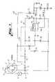
- FIG. 1is a schematic view of a motor starting device in accordance with the present invention.
- FIG. 2is a schematic view of the control circuit which is part of the motor starting device illustrated in FIG. 1 .
- FIG. 1discloses a motor 10 and a motor starting device 20 .
- the motor 10is a single-phase permanent split-capacitor (PSC) induction motor with two windings, a main run winding 14 and a start winding 12 .
- a single phase AC voltage source 2is connected to the motor windings 12 and 14 by lines 4 and 6 through a motor switch 9 .
- the line 4is connected via the motor switch 9 to a common node 3 .
- the line 6is connected to the other side of run winding 14 at a node 5 .
- a start capacitor 16is connected between the run winding 14 at the node 5 and the start winding 12 at a node 7 .
- the foregoing description of the motor 10 connected to the AC voltage source 2 via the motor switch 9is conventional.
- the start capacitor 16is selected as a compromise between startup torque and run torque. Where the motor 10 is used to drive machinery, such as an air conditioner compressor, the required starting torque may increase as the air-conditioning compressor ages and parts become worn. Consequently, the existing start capacitor 16 , may not provide sufficient phase shift to produce the required starting torque for the worn and aging compressor. In order to increase the starting torque for the motor 10 , an auxiliary start capacitor 22 may be connected in parallel with the existing start capacitor 16 . The additional capacitance provided by the auxiliary start capacitor 22 further shifts the phase between the run winding 14 and the start winding 12 to thus provide additional startup torque.
- the auxiliary start capacitor 22is part of the motor starting device 20 .
- the motor starting device 20thus comprises the auxiliary start capacitor 22 , a relay 52 including a relay coil 54 ( FIG. 2 ) and a normally closed relay switch 56 for connecting the auxiliary start capacitor 22 in parallel with the start capacitor 16 , a full wave rectifier 30 , and a control circuit 60 for controlling the operation of the relay 52 and thereby the normally closed relay switch 56 .
- the relay 52may be replaced by a solid-state switching device such as a silicon control rectifier (SCR) or a Triac which, like the relay 52 , comprise a switch and a switch activation circuit.
- SCRsilicon control rectifier
- TriacTriac
- the motor starting device 20is connected to the existing start capacitor 16 at the nodes 5 and 7 .
- the nodes 5 and 7are connected to the full wave rectifier 30 which comprises diodes 32 , 34 , 36 , and 38 .
- the junction between the diodes 32 and 34is connected to ground, and junction between the diodes 36 and 38 is a positive DC voltage V+.
- the DC voltage V+is connected to the control circuit 60 by means of a line 40 .
- two additional DC reference voltages, Ref. 1 and Ref. 2are derived from V+ by means of zener diodes 41 and 43 .
- the DC voltage Ref. 1is approximately 17.1 volts
- the DC voltage Ref. 2is approximately 12.1 volts.
- the DC reference voltages, Ref. 1 and Ref. 2are connected to the control circuit 60 by means of the lines 42 and 44 respectively.
- a relay protection circuitincludes the diodes 48 and 50 shown in FIG. 1 .
- the anode of the diode 48is connected to ground, and the cathode of the diode 48 is connected to the junction between the auxiliary start capacitor 22 and the relay switch 56 .
- the cathode of the diode 50is connected to V+, and the anode of the diode 50 is connected to the junction between the auxiliary start capacitor 22 and the relay switch 56 .
- the diodes 48 and 50serve to maintain the voltage of V+ when the AC voltage source 2 has been disconnected from the motor 10 by opening the motor switch 9 and while charge still remains on the auxiliary start capacitor 22 .
- the diodes 32 and 36serve to maintained the voltage of V+ when the AC voltage source 2 has been disconnected from the motor 10 and while charge still remains on the start capacitor 16 .
- the control circuit 60controls the opening and closing of the relay switch 56 by energizing and deenergizing the relay coil 54 of the relay 52 .
- the control circuit 60comprises a timer/voltage sensor circuit 62 and a relay coil driver circuit 72 .
- the timer/voltage sensor circuit 62monitors the value of V+, and after a delay time dependent on the value of V+, the timer/voltage sensor circuit 62 activates the relay coil driver circuit 72 .
- the relay coil driver circuit 72is a multivibrator which, when activated, maintains sufficient current through the relay coil 54 to ensure that the relay switch 56 remains open while the motor 10 is running and thereafter until the charge has dissipated from the start capacitor 16 and the auxiliary start capacitor 22 .
- the timer/sensor circuit 62 of the control circuit 60is connected to the V+ voltage and produces an output signal on an output 92 .
- the output 92is connected to the relay coil driver circuit 72 .
- the timer/sensor circuit 62has a pair of switching transistors 64 and 66 connected between the higher reference voltage Ref. 1 on line 42 and the lower reference voltage Ref. 2 on line 44 . As long as transistors 64 and 66 remain in the off condition, the collector of transistor 66 remains at ground potential and the output signal on the output 92 remains at ground potential. With the output signal on the output 92 at ground potential, the relay coil driver circuit 72 remains inactive, no current flows in the relay coil 54 , the relay switch 56 remains closed, and the auxiliary start capacitor 22 remains connected in parallel with the start capacitor 16 .
- the switching transistors 64 and 66 of the timer/voltage sensor circuit 62are controlled by a timer circuit 70 and a voltage sensor 68 connected to the base of the transistor 64 .
- the base voltage of transistor 64is controlled by the charge on a timing capacitor 73 connected between the base of the transistor 64 and ground.
- the voltage on the timing capacitor 73and therefore the voltage on the base of the transistor 64 , is dynamically controlled by the time constant of the timer circuit 70 represented by the value of the timing capacitor 73 , the value of resisters 67 and 75 , and the setting of potentiometer 71 .
- the voltage sensor 68consisting of resistors 67 and 69 is connected between V+ and ground to produce a steady state DC voltage at node 65 which is sufficient to turn on the transistors 64 and 66 through diode 77 .
- the transistor 64will turn on thereby turning on the transistor 66 .
- the flow of current through the transistor 66 and through the resistor 79raises the voltage potential of the collector of the transistor 66 to provide an output signal through a resistor 81 on the output 92 of the timer/voltage sensor circuit 62 .
- the output signal on the output 92is connected to the relay coil driver circuit 72 .
- the relay coil driver circuit 72is a multivibrator consisting of a transistor 74 and a field effect transistor (FET) 76 .
- the input of the relay coil driver circuit 72is the collector of the transistor 74 .
- the input of the relay coil driver circuit 72is connected to output 92 of the timer/voltage sensor circuit 62 .
- the collector of the transistor 74is connected to the gate of the FET 76 via a gate drive circuit 84 .
- the voltage of the gate drive circuit 84thereby turns on and turns off the FET 76 .
- the drain of the FET 76is connected to ground via a drain resistor 90 .
- the source of the FET 76is connected to V+ via the relay coil 54 and a light emitting diode (LED) 82 .
- a shunt diodeis connected in parallel with the relay coil 54 of the relay 52 to maintained the inductive energy in the relay coil when the FET 76 is turned off.
- the FET 76has a dynamic feedback path 78 and a static feedback path 88 .
- the dynamic feedback path 78is connected to the source of the FET 76 .
- the static feedback path 88is connected to the drain of the FET 76 .
- Both the dynamic feedback path 78 and the static feedback path 88are connected to the base of the transistor 74 to turn the transistor 74 off and on.
- the emitter of the transistor 74is connected to ground through two diodes which provide a stable offset voltage from ground.
- the motor starting device 20controls the connection and disconnection of the auxiliary start capacitor 22 in parallel with the start capacitor 16 .
- the motor starting device 20connects the auxiliary start capacitor 22 in parallel with the existing start capacitor 16 by means of the normally closed relay switch 56 .
- the motor starting device 20disconnects the auxiliary start capacitor 22 from the existing start capacitor 16 by opening the relay switch 56 once an adjustable delay time has elapsed.
- the motor starting device 20holds the relay switch 56 open until the charge has dissipated from both the start capacitor 16 and the auxiliary start capacitor 22 .
- V+is at zero potential ( FIG. 1 ). With V+ at zero potential, the FET 76 is it the off condition, and no current flows through the relay coil 54 ( FIG. 2 ). Without current is the relay coil 54 , the normally closed relay switch 56 is closed, and the auxiliary start capacitor 22 is connected in parallel with the start capacitor 16 .
- the motor 10begins to rotate using the phase shift created by the parallel combination of the existing start capacitor 16 and the auxiliary start capacitor 22 .
- the full wave rectifier 30converts the AC voltage supplied by the AC voltage source 2 between the node 5 and the node 7 to a DC voltage, V+, on the line 40 .
- the reference voltages, Ref. 1 (about 17.1 volts) and Ref. 2 (about 12.1 volts)are derived from V+ with the zener diodes 41 and 43 .
- V+is connected to the timer/voltage sensor circuit 62 .
- the charge on the timing capacitor 73is zero, and the transistors 64 and 66 are both in their off condition.
- the output signal on output 92 of timer/voltage sensor circuit 62remains at ground potential.
- the collector of the transistor 74 of the relay coil driver circuit 72likewise remains at ground potential. Because the collector of the transistor 74 is at ground potential, the FET 76 is in the off condition. With the FET 76 in the off condition, no current flows through the relay coil 54 . Without current through the relay coil 54 , the normally closed relay switch 56 remains closed, and the auxiliary start capacitor 22 remains connected in parallel with the start capacitor 16 .
- the voltage on the timing capacitor 73begins increasing. Once the voltage on the timing capacitor 73 has reached a value above the reference voltage Ref. 2 , the transistor 64 will begin conducting.
- the time delay for the buildup of voltage on the timing capacitor 73is set by the RC time constant established by the value of the timing capacitor 73 and the series value of the resistor 75 and the potentiometer 71 . RC time constant and therefore the delay time for the timing capacitor to charge can be adjusted by means of the potentiometer 71 .
- a variable capacitor in place of the timing capacitor 73could also be used to control the delay time before the transistor 64 is turned on.
- the delay timeis also dependent on the value of the AC voltage of the AC voltage source 2 . If the voltage of the AC voltage source 2 is normal, V+ will be relatively high, and charge will be added to the timing capacitor 73 through the resistor 67 and the diode 77 . That parallel charge path will speed up the charging of the timing capacitor 73 and shorten the delay time. If, on the other hand, the AC voltage of the AC voltage source 2 is relatively low, V+ will be relatively low and will not contribute to the buildup of charge on the timing capacitor 73 through the diode 77 thereby increasing the delay time.
- the delay timewill be controlled by the RC time constant established by the value of the timing capacitor 73 and the series combination of the resistor 75 and the potentiometer 70 . Consequently, the voltage on the timing capacitor 73 will reach the turn on voltage for the transistor 64 more quickly if the AC voltage is high then it will if the AC voltage is low.
- the transistor 64will turn on. Once transistor 64 has turned on, it will turn on the transistor 66 . As current flows from Ref. 1 connected to the emitter of the transistor 66 to the collector of the transistor 66 , that current, passing through the resistor 79 , will cause the voltage on the collector of the transistor 66 to rise above ground. Consequently, the output signal of the timer/voltage sensor circuit 62 on output 92 will be positive thereby indicating to the relay coil driver circuit 72 that the auxiliary start capacitor 22 has accomplished its purpose and that the relay coil 54 should be energized to disconnected the capacitor 22 .
- the relay coil driver circuit 72receives the positive voltage input from the timer/voltage sensor circuit 62 at output 92 . In response, the relay coil driver circuit 72 energizes the relay driver coil 54 to open the relay driver switch 56 . In order to energize the relay driver coil 54 , the FET 76 is turned on by the positive voltage from the timer/voltage sensor circuit 62 at the collector of the transistor 74 , and current flows from V+ to ground through the relay driver coil 54 . As the current flows through the FET 76 , the voltage at the drain of the FET 76 rises as a result of the current flowing through the drain resistor 90 .
- the voltage at the base of the transistor 74 resulting from the static feedback path 88is sufficiently high to turn on transistor 74 .
- the collector of the transistor 74is pulled toward a lower voltage of approximately 1.6 volts (the voltage drop across the two diodes connected to the emitter of the transistor 74 plus the collector/emitter drop of the transistor 74 ).
- the FET 76will turn off as a result of the voltage in the gate drive circuit 84 .
- the FET 76turns off, the voltage on the resistor 90 will return to ground potential and the transistor 74 will subsequently turn off.
- the relay coil driver circuit 72will oscillate with the FET 76 turning on and off.
- the frequency of the oscillationis determined primarily by the value of the inductance of the relay coil 54 and the resistor 90 .
- the duty cycle of the FET 76is sufficient to maintain enough current in the relay coil 54 to hold the relay switch 56 open.
- the light emitting diode (LED) 82will glow indicating that the relay coil 54 is energized, that the relay switch 56 is open, and that the auxiliary start capacitor 22 is disconnected.
- the start capacitor 16 and the auxiliary start capacitor 22may be polarized such that a substantial potential exists across the open contacts of the relay switch 56 . If the relay switch 56 is allowed to close immediately upon the removal of the AC voltage source 2 , the existing potential across the contacts of the relay switch 56 may be sufficient to weld or burn the contacts of the relay switch 56 . Consequently, the relay switch 56 must remain open until the residual charges on the start capacitor 16 and on the auxiliary start capacitor 22 have dissipated. In order to accomplish that function, a relay protection circuit is employed.
- the relay protection circuitcomprises diodes 48 and 50 , in conjunction with diodes 34 and 38 , for receiving the charge from auxiliary start capacitor 22 and diodes 32 and 36 , in conjunction with diodes 34 and 38 for receiving the charge from start capacitor 16 .
- the diodes 48 and 50in conjunction with diodes 34 and 38 , rectify the voltage from the auxiliary start capacitor 22 to maintain the voltage V+.
- the diodes 32 and 36in conjunction with diodes 34 and 38 , rectify the voltage from the start capacitor 16 to maintain the voltage V+. As long as the voltage V+ remains above a preestablished level, the voltage at the node 65 of the voltage divider 68 of the timer/voltage sensor circuit 62 ( FIG.
Landscapes
- Engineering & Computer Science (AREA)
- Power Engineering (AREA)
- Motor And Converter Starters (AREA)
Abstract
Description
Claims (20)
Priority Applications (1)
| Application Number | Priority Date | Filing Date | Title |
|---|---|---|---|
| US10/798,238US6982539B1 (en) | 2004-03-11 | 2004-03-11 | Motor starting device |
Applications Claiming Priority (1)
| Application Number | Priority Date | Filing Date | Title |
|---|---|---|---|
| US10/798,238US6982539B1 (en) | 2004-03-11 | 2004-03-11 | Motor starting device |
Publications (1)
| Publication Number | Publication Date |
|---|---|
| US6982539B1true US6982539B1 (en) | 2006-01-03 |
Family
ID=35509054
Family Applications (1)
| Application Number | Title | Priority Date | Filing Date |
|---|---|---|---|
| US10/798,238Expired - LifetimeUS6982539B1 (en) | 2004-03-11 | 2004-03-11 | Motor starting device |
Country Status (1)
| Country | Link |
|---|---|
| US (1) | US6982539B1 (en) |
Cited By (35)
| Publication number | Priority date | Publication date | Assignee | Title |
|---|---|---|---|---|
| US20060284590A1 (en)* | 2005-06-01 | 2006-12-21 | Somfy Sas | Actuator for operating a roller blind and method of operating such an actuator |
| US20070253133A1 (en)* | 2006-04-28 | 2007-11-01 | Danfoss Compressors Gmbh | Motor starter circuit |
| US20080018293A1 (en)* | 2006-07-19 | 2008-01-24 | Danfoss Compressors Gmbh | Motor start circuit |
| US20080225447A1 (en)* | 2006-11-07 | 2008-09-18 | Danfoss Compressors Gmbh | Motor start circuit |
| WO2009114198A1 (en)* | 2008-03-13 | 2009-09-17 | International Controls And Measurements Corp. | Motor start circuit with capacitive discharge protection |
| CN101309059B (en)* | 2008-06-19 | 2010-05-12 | 张功元 | Single-phase capacitor motor controller of single-phase electric power used in building hanging cradle |
| US20130264991A1 (en)* | 2010-09-20 | 2013-10-10 | Whirlpool S.A. | Start and control method for a single-phase induction motor, a start and control system for a single-phase induction motor and an electronic start and control device applied to a single-phase induction motor |
| US9318261B2 (en) | 2013-05-21 | 2016-04-19 | American Radionic Company, Inc. | Power factor correction capacitors |
| US9324501B2 (en) | 2009-11-13 | 2016-04-26 | American Radionic Company, Inc. | Hard start kit for multiple replacement applications |
| US20160118920A1 (en)* | 2014-10-27 | 2016-04-28 | Denso Corporation | Power generator with load-dump protection |
| US9343238B2 (en) | 2005-04-07 | 2016-05-17 | American Radionic Company, Inc. | Capacitor for multiple replacement applications |
| US9378893B2 (en) | 2005-04-07 | 2016-06-28 | American Radionic Company, Inc. | Capacitor with multiple elements for multiple replacement applications |
| US9412521B2 (en) | 2005-04-07 | 2016-08-09 | American Radionic Company, Inc. | Capacitor with multiple elements for multiple replacement applications |
| US9424995B2 (en) | 2006-12-29 | 2016-08-23 | American Radionic Company, Inc. | Electrolytic capacitor |
| US9479104B1 (en)* | 2015-04-14 | 2016-10-25 | Nidec Motor Corporation | System and method for timed insertion of a phase shift capacitor upon powering a split capacitor electrical motor |
| WO2016182644A1 (en)* | 2015-05-12 | 2016-11-17 | Illinois Tool Works Inc. | Commerical compressor with electronic start device for the start of the electric motor |
| US20170346421A1 (en)* | 2016-05-30 | 2017-11-30 | Johnson Electric S.A. | Motor Driving Circuit, Motor Driving Method, and Motor Utilizing the Same |
| US9859060B1 (en) | 2017-02-07 | 2018-01-02 | American Radionic Company, Inc. | Capacitor with multiple elements for multiple replacement applications |
| USD818437S1 (en) | 2005-12-23 | 2018-05-22 | American Radionic Company, Inc. | Capacitor |
| US10147550B1 (en) | 2018-04-27 | 2018-12-04 | American Radionic Company, Inc. | Capacitor with multiple elements for multiple replacement applications |
| US10497518B1 (en) | 2017-12-13 | 2019-12-03 | American Radionic Company, Inc. | Hard start kit for multiple replacement applications |
| US10586655B1 (en) | 2018-12-28 | 2020-03-10 | American Radionic Company, Inc. | Capacitor with multiple elements for multiple replacement applications |
| USD906247S1 (en) | 2019-07-11 | 2020-12-29 | American Radionic Company, Inc. | Capacitor |
| US11183337B1 (en) | 2005-04-07 | 2021-11-23 | Amrad Manufacturing, Llc | Capacitor with multiple elements for multiple replacement applications |
| US11183336B2 (en) | 2005-04-07 | 2021-11-23 | Amrad Manufacturing, Llc | Capacitor with multiple elements for multiple replacement applications |
| US11183338B2 (en) | 2005-04-07 | 2021-11-23 | Amrad Manufacturing, Llc | Capacitor with multiple elements for multiple replacement applications |
| US11195663B2 (en) | 2017-05-12 | 2021-12-07 | Amrad Manufacturing, Llc | Capacitor with multiple elements for multiple replacement applications |
| US11424077B1 (en) | 2017-12-13 | 2022-08-23 | Amrad Manufacturing, Llc | Hard start kit for multiple replacement applications |
| US11575298B2 (en) | 2021-04-30 | 2023-02-07 | Amrad Manufacturing, Llc | Hard start kit for multiple replacement applications |
| US12125645B1 (en) | 2019-06-07 | 2024-10-22 | Amrad Manufacturing, Llc | Capacitor with multiple elements for multiple replacement applications |
| USD1052528S1 (en) | 2019-06-25 | 2024-11-26 | Amrad Manufacturing, Llc | Capacitor |
| USD1054379S1 (en) | 2020-11-24 | 2024-12-17 | Amrad Manufacturing, Llc | Capacitor with relay |
| USD1055860S1 (en) | 2018-12-13 | 2024-12-31 | Amrad Manufacturing, Llc | Magnet for attachment to a capacitor |
| US12272503B2 (en) | 2017-05-12 | 2025-04-08 | Amrad Manufacturing, Llc | Capacitor with multiple elements for multiple replacement applications |
| US12437918B2 (en) | 2023-09-22 | 2025-10-07 | Amrad Manufacturing, Llc | Capacitor mount |
Citations (25)
| Publication number | Priority date | Publication date | Assignee | Title |
|---|---|---|---|---|
| US3549970A (en) | 1967-12-20 | 1970-12-22 | Alexander J Lewus | Single-phase motor controls with combination overload protector and starting switch |
| US3784846A (en) | 1972-04-24 | 1974-01-08 | Rowan Controller | Solid state motor controller for disconnecting a motor from a power source when a predetermined undervoltage condition persists for a predetermined time |
| US4042964A (en) | 1975-12-15 | 1977-08-16 | Robertshaw Controls Company | Motor protection circuit |
| US4196462A (en) | 1978-05-30 | 1980-04-01 | General Electric Company | Protective control circuit for induction motors |
| US4200829A (en) | 1978-07-12 | 1980-04-29 | General Electric Company | Circuit for protecting induction motors |
| US4366426A (en) | 1981-09-08 | 1982-12-28 | S.A. Armstrong Limited | Starting circuit for single phase electric motors |
| US4727297A (en) | 1986-07-17 | 1988-02-23 | Peak Systems, Inc. | Arc lamp power supply |
| US4751450A (en)* | 1986-09-24 | 1988-06-14 | Pt Components, Inc. | Low cost, protective start from coast circuit |
| US4751449A (en)* | 1986-09-24 | 1988-06-14 | Pt Components, Inc. | Start from coast protective circuit |
| US4772808A (en) | 1986-01-17 | 1988-09-20 | Vial Jean Luc | Control device for electrical appliances |
| US4786850A (en) | 1987-08-13 | 1988-11-22 | Pt Components, Inc. | Motor starting circuit with time delay cut-out and restart |
| US4804901A (en) | 1987-11-13 | 1989-02-14 | Kilo-Watt-Ch-Dog, Inc. | Motor starting circuit |
| US4820964A (en) | 1986-08-22 | 1989-04-11 | Andrew S. Kadah | Solid state motor start circuit |
| US4906857A (en) | 1988-12-12 | 1990-03-06 | Kikusui Line Co., Ltd. | Electronic starting motor control having fail safe and overvoltage protection |
| US4917411A (en) | 1988-12-12 | 1990-04-17 | General Motors Corporation | Electronic starting motor control with low voltage protection |
| US5051681A (en)* | 1989-11-28 | 1991-09-24 | Empresa Brasileira De Compressores S/A Embarco | Electronic circuit for a single phase induction motor starting |
| US5103154A (en) | 1990-05-25 | 1992-04-07 | Texas Instruments Incorporated | Start winding switch protection circuit |
| US5162718A (en) | 1989-08-31 | 1992-11-10 | Schroeder Fritz H | Starting device and circuit for starting single phase motors |
| US5206573A (en) | 1991-12-06 | 1993-04-27 | Mccleer Arthur P | Starting control circuit |
| US5247236A (en) | 1989-08-31 | 1993-09-21 | Schroeder Fritz H | Starting device and circuit for starting single phase motors |
| US5296795A (en) | 1992-10-26 | 1994-03-22 | Texas Instruments Incorporated | Method and apparatus for starting capacitive start, induction run and capacitive start, capacitive run electric motors |
| US5528120A (en) | 1994-09-09 | 1996-06-18 | Sealed Unit Parts Co., Inc. | Adjustable electronic potential relay |
| US5561357A (en) | 1995-04-24 | 1996-10-01 | Schroeder; Fritz H. | Starting device and circuit for starting single phase motors |
| US6320348B1 (en) | 1999-06-14 | 2001-11-20 | Andrew S. Kadah | Time rate of change motor start circuit |
| US6407530B1 (en) | 1999-11-12 | 2002-06-18 | Lg Electronics Inc. | Device and method for controlling supply of current and static capacitance to compressor |
- 2004
- 2004-03-11USUS10/798,238patent/US6982539B1/ennot_activeExpired - Lifetime
Patent Citations (25)
| Publication number | Priority date | Publication date | Assignee | Title |
|---|---|---|---|---|
| US3549970A (en) | 1967-12-20 | 1970-12-22 | Alexander J Lewus | Single-phase motor controls with combination overload protector and starting switch |
| US3784846A (en) | 1972-04-24 | 1974-01-08 | Rowan Controller | Solid state motor controller for disconnecting a motor from a power source when a predetermined undervoltage condition persists for a predetermined time |
| US4042964A (en) | 1975-12-15 | 1977-08-16 | Robertshaw Controls Company | Motor protection circuit |
| US4196462A (en) | 1978-05-30 | 1980-04-01 | General Electric Company | Protective control circuit for induction motors |
| US4200829A (en) | 1978-07-12 | 1980-04-29 | General Electric Company | Circuit for protecting induction motors |
| US4366426A (en) | 1981-09-08 | 1982-12-28 | S.A. Armstrong Limited | Starting circuit for single phase electric motors |
| US4772808A (en) | 1986-01-17 | 1988-09-20 | Vial Jean Luc | Control device for electrical appliances |
| US4727297A (en) | 1986-07-17 | 1988-02-23 | Peak Systems, Inc. | Arc lamp power supply |
| US4820964A (en) | 1986-08-22 | 1989-04-11 | Andrew S. Kadah | Solid state motor start circuit |
| US4751449A (en)* | 1986-09-24 | 1988-06-14 | Pt Components, Inc. | Start from coast protective circuit |
| US4751450A (en)* | 1986-09-24 | 1988-06-14 | Pt Components, Inc. | Low cost, protective start from coast circuit |
| US4786850A (en) | 1987-08-13 | 1988-11-22 | Pt Components, Inc. | Motor starting circuit with time delay cut-out and restart |
| US4804901A (en) | 1987-11-13 | 1989-02-14 | Kilo-Watt-Ch-Dog, Inc. | Motor starting circuit |
| US4906857A (en) | 1988-12-12 | 1990-03-06 | Kikusui Line Co., Ltd. | Electronic starting motor control having fail safe and overvoltage protection |
| US4917411A (en) | 1988-12-12 | 1990-04-17 | General Motors Corporation | Electronic starting motor control with low voltage protection |
| US5162718A (en) | 1989-08-31 | 1992-11-10 | Schroeder Fritz H | Starting device and circuit for starting single phase motors |
| US5247236A (en) | 1989-08-31 | 1993-09-21 | Schroeder Fritz H | Starting device and circuit for starting single phase motors |
| US5051681A (en)* | 1989-11-28 | 1991-09-24 | Empresa Brasileira De Compressores S/A Embarco | Electronic circuit for a single phase induction motor starting |
| US5103154A (en) | 1990-05-25 | 1992-04-07 | Texas Instruments Incorporated | Start winding switch protection circuit |
| US5206573A (en) | 1991-12-06 | 1993-04-27 | Mccleer Arthur P | Starting control circuit |
| US5296795A (en) | 1992-10-26 | 1994-03-22 | Texas Instruments Incorporated | Method and apparatus for starting capacitive start, induction run and capacitive start, capacitive run electric motors |
| US5528120A (en) | 1994-09-09 | 1996-06-18 | Sealed Unit Parts Co., Inc. | Adjustable electronic potential relay |
| US5561357A (en) | 1995-04-24 | 1996-10-01 | Schroeder; Fritz H. | Starting device and circuit for starting single phase motors |
| US6320348B1 (en) | 1999-06-14 | 2001-11-20 | Andrew S. Kadah | Time rate of change motor start circuit |
| US6407530B1 (en) | 1999-11-12 | 2002-06-18 | Lg Electronics Inc. | Device and method for controlling supply of current and static capacitance to compressor |
Cited By (88)
| Publication number | Priority date | Publication date | Assignee | Title |
|---|---|---|---|---|
| US11183336B2 (en) | 2005-04-07 | 2021-11-23 | Amrad Manufacturing, Llc | Capacitor with multiple elements for multiple replacement applications |
| US11183337B1 (en) | 2005-04-07 | 2021-11-23 | Amrad Manufacturing, Llc | Capacitor with multiple elements for multiple replacement applications |
| US10056194B2 (en) | 2005-04-07 | 2018-08-21 | American Radionic Company, Inc. | Capacitor with multiple elements for multiple replacement applications |
| US10134528B2 (en) | 2005-04-07 | 2018-11-20 | American Radionic Company, Inc. | Capacitor for multiple replacement applications |
| US10249439B2 (en) | 2005-04-07 | 2019-04-02 | American Radionic Company, Inc. | Capacitor for multiple replacement applications |
| US12278059B2 (en) | 2005-04-07 | 2025-04-15 | Amrad Manufacturing, Llc | Capacitor with multiple elements for multiple replacement applications |
| US12272501B2 (en) | 2005-04-07 | 2025-04-08 | Amrad Manufacturing, Llc | Capacitor for multiple replacement applications |
| US10475588B2 (en) | 2005-04-07 | 2019-11-12 | American Radionic Company, Inc. | Capacitor with multiple elements for multiple replacement applications |
| US10497520B1 (en) | 2005-04-07 | 2019-12-03 | American Radionic Company, Inc. | Capacitor for multiple replacement applications |
| US12260998B2 (en) | 2005-04-07 | 2025-03-25 | Amrad Manufacturing, Llc | Capacitor with multiple elements for multiple replacement applications |
| US11177074B1 (en) | 2005-04-07 | 2021-11-16 | Amrad Manufacturing, Llc | Capacitor for multiple replacement applications |
| US9536670B2 (en) | 2005-04-07 | 2017-01-03 | American Radionic Company, Inc. | Capacitor with multiple elements for multiple replacement applications |
| US12230452B1 (en) | 2005-04-07 | 2025-02-18 | Amrad Manufacturing, Llc | Capacitor with multiple elements for multiple replacement applications |
| US11651903B1 (en) | 2005-04-07 | 2023-05-16 | Amrad Manufacturing, Llc | Capacitor for multiple replacement applications |
| US12224132B1 (en) | 2005-04-07 | 2025-02-11 | Amrad Manufacturing, Llc | Capacitor with multiple elements for multiple replacement applications |
| US11183338B2 (en) | 2005-04-07 | 2021-11-23 | Amrad Manufacturing, Llc | Capacitor with multiple elements for multiple replacement applications |
| US9412521B2 (en) | 2005-04-07 | 2016-08-09 | American Radionic Company, Inc. | Capacitor with multiple elements for multiple replacement applications |
| US9378893B2 (en) | 2005-04-07 | 2016-06-28 | American Radionic Company, Inc. | Capacitor with multiple elements for multiple replacement applications |
| US11189426B1 (en) | 2005-04-07 | 2021-11-30 | Amrad Manufacturing, Llc | Capacitor with multiple elements for multiple replacement applications |
| US9343238B2 (en) | 2005-04-07 | 2016-05-17 | American Radionic Company, Inc. | Capacitor for multiple replacement applications |
| US20060284590A1 (en)* | 2005-06-01 | 2006-12-21 | Somfy Sas | Actuator for operating a roller blind and method of operating such an actuator |
| US7692398B2 (en)* | 2005-06-01 | 2010-04-06 | Somfy Sas | Actuator for operating a roller blind and method of operating such an actuator |
| USD1045798S1 (en) | 2005-12-23 | 2024-10-08 | Amrad Manufacturing, Llc | Capacitor |
| USD829173S1 (en) | 2005-12-23 | 2018-09-25 | American Radionic Company, Inc. | Capacitor |
| USD938912S1 (en) | 2005-12-23 | 2021-12-21 | Amrad Manufacturing, Llc | Capacitor |
| USD818437S1 (en) | 2005-12-23 | 2018-05-22 | American Radionic Company, Inc. | Capacitor |
| USD818959S1 (en) | 2005-12-23 | 2018-05-29 | American Radionic Company, Inc. | Capacitor |
| US20070253133A1 (en)* | 2006-04-28 | 2007-11-01 | Danfoss Compressors Gmbh | Motor starter circuit |
| US7630180B2 (en) | 2006-04-28 | 2009-12-08 | Danfoss Compressors Gmbh | Motor starter circuit |
| CN101110558B (en)* | 2006-07-19 | 2010-12-08 | 丹佛斯压缩机有限责任公司 | Motor start circuit |
| US7777438B2 (en) | 2006-07-19 | 2010-08-17 | Danfoss Compressors Gmbh | Motor start circuit |
| DE102006034499A1 (en)* | 2006-07-19 | 2008-01-31 | Danfoss Compressors Gmbh | Motor start circuit |
| US20080018293A1 (en)* | 2006-07-19 | 2008-01-24 | Danfoss Compressors Gmbh | Motor start circuit |
| US7777992B2 (en)* | 2006-11-07 | 2010-08-17 | Danfoss Compressors Gmbh | Motor start circuit |
| US20080225447A1 (en)* | 2006-11-07 | 2008-09-18 | Danfoss Compressors Gmbh | Motor start circuit |
| US9424995B2 (en) | 2006-12-29 | 2016-08-23 | American Radionic Company, Inc. | Electrolytic capacitor |
| US12293879B2 (en) | 2006-12-29 | 2025-05-06 | Amrad Manufacturing, Llc | Electrolytic capacitive device |
| US11631550B2 (en) | 2006-12-29 | 2023-04-18 | Amrad Manufacturing, Llc | Electrolytic capacitor with multiple sections |
| US11183341B1 (en) | 2006-12-29 | 2021-11-23 | Amrad Manufacturing, Llc | Electrolytic capacitive device |
| US10056195B2 (en) | 2006-12-29 | 2018-08-21 | American Radionic Company, Inc. | Electrolytic Capacitor |
| US7804270B2 (en) | 2008-03-13 | 2010-09-28 | International Controls And Measurements Corp. | Motor start circuit with capacitive discharge protection |
| WO2009114198A1 (en)* | 2008-03-13 | 2009-09-17 | International Controls And Measurements Corp. | Motor start circuit with capacitive discharge protection |
| US20090230914A1 (en)* | 2008-03-13 | 2009-09-17 | International Controls And Measurements Corporation | Motor Start Circuit with Capacitive Discharge Protection |
| CN101309059B (en)* | 2008-06-19 | 2010-05-12 | 张功元 | Single-phase capacitor motor controller of single-phase electric power used in building hanging cradle |
| US12237115B1 (en) | 2009-11-13 | 2025-02-25 | Amrad Manufacturing Llc | Hard start kit for multiple replacement applications |
| US12224131B1 (en) | 2009-11-13 | 2025-02-11 | Amrad Manufacturing, Llc | Hard start kit for multiple replacement applications |
| US10163571B2 (en) | 2009-11-13 | 2018-12-25 | American Radionic Co., Inc. | Hard start kit for multiple replacement applications |
| US9324501B2 (en) | 2009-11-13 | 2016-04-26 | American Radionic Company, Inc. | Hard start kit for multiple replacement applications |
| US20130264991A1 (en)* | 2010-09-20 | 2013-10-10 | Whirlpool S.A. | Start and control method for a single-phase induction motor, a start and control system for a single-phase induction motor and an electronic start and control device applied to a single-phase induction motor |
| US9160259B2 (en)* | 2010-09-20 | 2015-10-13 | Whirlpool S.A. | Start and control method for a single-phase induction motor, a start and control system for a single-phase induction motor and an electronic start and control device applied to a single-phase induction motor |
| US12230451B2 (en) | 2013-05-21 | 2025-02-18 | Amrad Manufacturing, Llc | Power factor correction capacitors |
| US9496086B2 (en) | 2013-05-21 | 2016-11-15 | American Radionic Company, Inc. | Power factor correction capacitors |
| US10147549B2 (en) | 2013-05-21 | 2018-12-04 | American Radionic Company, Inc. | Power factor correction capacitors |
| US9318261B2 (en) | 2013-05-21 | 2016-04-19 | American Radionic Company, Inc. | Power factor correction capacitors |
| US11183335B2 (en) | 2013-05-21 | 2021-11-23 | Amrad Manufacturing, Llc | Power factor correction capacitors |
| US11189425B1 (en) | 2013-05-21 | 2021-11-30 | Amrad Manufacturing, Llc | Power factor correction capacitors |
| US20160118920A1 (en)* | 2014-10-27 | 2016-04-28 | Denso Corporation | Power generator with load-dump protection |
| US9628007B2 (en)* | 2014-10-27 | 2017-04-18 | Denso Corporation | Power generator with load-dump protection |
| US9479104B1 (en)* | 2015-04-14 | 2016-10-25 | Nidec Motor Corporation | System and method for timed insertion of a phase shift capacitor upon powering a split capacitor electrical motor |
| US10027258B2 (en) | 2015-05-12 | 2018-07-17 | Illinois Tool Works Inc. | Commercial compressor with electronic start device for the start of the electric motor |
| WO2016182644A1 (en)* | 2015-05-12 | 2016-11-17 | Illinois Tool Works Inc. | Commerical compressor with electronic start device for the start of the electric motor |
| US10270374B2 (en)* | 2016-05-30 | 2019-04-23 | Johnson Electric International AG | Motor driving circuit, motor driving method, and motor utilizing the same |
| US20170346421A1 (en)* | 2016-05-30 | 2017-11-30 | Johnson Electric S.A. | Motor Driving Circuit, Motor Driving Method, and Motor Utilizing the Same |
| US10366840B1 (en) | 2017-02-07 | 2019-07-30 | American Radionic Company, Inc. | Capacitor with multiple elements for multiple replacement applications |
| US9859060B1 (en) | 2017-02-07 | 2018-01-02 | American Radionic Company, Inc. | Capacitor with multiple elements for multiple replacement applications |
| US12260997B2 (en) | 2017-05-12 | 2025-03-25 | Amrad Manufacturing, Llc | Capacitor with multiple elements for multiple replacement applications |
| US11195663B2 (en) | 2017-05-12 | 2021-12-07 | Amrad Manufacturing, Llc | Capacitor with multiple elements for multiple replacement applications |
| US12308179B2 (en) | 2017-05-12 | 2025-05-20 | Amrad Manufacturing, Llc | Capacitor with multiple elements for multiple replacement applications |
| US12272503B2 (en) | 2017-05-12 | 2025-04-08 | Amrad Manufacturing, Llc | Capacitor with multiple elements for multiple replacement applications |
| US12191087B2 (en) | 2017-05-12 | 2025-01-07 | Amrad Manufacturing, Llc | Capacitor with multiple elements for multiple replacement applications |
| US12211655B2 (en) | 2017-05-12 | 2025-01-28 | Amrad Manufacturing, Llc | Capacitor with multiple elements for multiple replacement applications |
| US10497518B1 (en) | 2017-12-13 | 2019-12-03 | American Radionic Company, Inc. | Hard start kit for multiple replacement applications |
| US11424077B1 (en) | 2017-12-13 | 2022-08-23 | Amrad Manufacturing, Llc | Hard start kit for multiple replacement applications |
| US10147550B1 (en) | 2018-04-27 | 2018-12-04 | American Radionic Company, Inc. | Capacitor with multiple elements for multiple replacement applications |
| USD1055860S1 (en) | 2018-12-13 | 2024-12-31 | Amrad Manufacturing, Llc | Magnet for attachment to a capacitor |
| US12230447B2 (en) | 2018-12-28 | 2025-02-18 | Amrad Manufacturing, Llc | Capacitor with multiple elements for multiple replacement applications |
| US12315679B2 (en) | 2018-12-28 | 2025-05-27 | Amrad Manufacturing, Llc | Capacitor with multiple elements for multiple replacement applications |
| US10586655B1 (en) | 2018-12-28 | 2020-03-10 | American Radionic Company, Inc. | Capacitor with multiple elements for multiple replacement applications |
| US11183330B2 (en) | 2018-12-28 | 2021-11-23 | Amrad Manufacturing, Llc | Capacitor with multiple elements for multiple replacement applications |
| US12125645B1 (en) | 2019-06-07 | 2024-10-22 | Amrad Manufacturing, Llc | Capacitor with multiple elements for multiple replacement applications |
| USD1054986S1 (en) | 2019-06-25 | 2024-12-24 | Amrad Manufacturing, Llc | Capacitor |
| USD1052528S1 (en) | 2019-06-25 | 2024-11-26 | Amrad Manufacturing, Llc | Capacitor |
| USD1059290S1 (en) | 2019-07-11 | 2025-01-28 | Amrad Manufacturing, Llc | Capacitor |
| USD906247S1 (en) | 2019-07-11 | 2020-12-29 | American Radionic Company, Inc. | Capacitor |
| USD1054379S1 (en) | 2020-11-24 | 2024-12-17 | Amrad Manufacturing, Llc | Capacitor with relay |
| US12260991B2 (en) | 2021-04-30 | 2025-03-25 | Amrad Manufacturing, Llc | Hard start kit for multiple replacement applications |
| US11575298B2 (en) | 2021-04-30 | 2023-02-07 | Amrad Manufacturing, Llc | Hard start kit for multiple replacement applications |
| US12437918B2 (en) | 2023-09-22 | 2025-10-07 | Amrad Manufacturing, Llc | Capacitor mount |
Similar Documents
| Publication | Publication Date | Title |
|---|---|---|
| US6982539B1 (en) | Motor starting device | |
| US5528120A (en) | Adjustable electronic potential relay | |
| EP1240709B1 (en) | Time rate of change motor start circuit | |
| US6989649B2 (en) | Switch assembly, electric machine having the switch assembly, and method of controlling the same | |
| EP1234372B1 (en) | Device and method for controlling supply of current and static capacitance to compressor | |
| US7061204B2 (en) | Motor starter device having reduced power consumption | |
| US4477766A (en) | Apparatus for controlling electric generation for vehicles | |
| JP3574145B2 (en) | Control device for vehicle alternator | |
| US20090034307A1 (en) | Protection Device for Electronic Converters, Related Converter and Method | |
| US5617001A (en) | A.C. motor starting control circuit utilizing triggerable semiconductor switching device | |
| US8258738B2 (en) | Low current electric motor starter | |
| US7514897B2 (en) | Control of a triac for the starting of a motor | |
| JP3519048B2 (en) | Voltage control device for vehicle alternator | |
| US20060017417A1 (en) | Electronic startup device for hermetic compressors | |
| JP3096553B2 (en) | Drive unit for blower fan | |
| EP1246354B1 (en) | Motor starter circuit, particularly for refrigerator compressors, having improved characteristics. | |
| WO2006001601A1 (en) | Starting circuit for electric motor | |
| JP2004266970A (en) | Rectification switching circuit | |
| JPH09161637A (en) | Power supply circuit for electromagnet exciting coil | |
| KR100598836B1 (en) | Starting switch for electric motor | |
| JPS5825756Y2 (en) | Dendo Kinokido Hoshiyou Cairo | |
| JP3661305B2 (en) | DC power supply | |
| JPS6114316Y2 (en) | ||
| KR100598827B1 (en) | Start switch for electric motor | |
| JP3888376B2 (en) | Discharge lamp lighting device |
Legal Events
| Date | Code | Title | Description |
|---|---|---|---|
| AS | Assignment | Owner name:DIVERSITECH CORPORATION, GEORGIA Free format text:ASSIGNMENT OF ASSIGNORS INTEREST;ASSIGNOR:WARD, CHARLES BARRY;REEL/FRAME:014731/0583 Effective date:20040309 | |
| AS | Assignment | Owner name:WACHOVIA BANK, NATIONAL ASSOCIATION, GEORGIA Free format text:SECURITY AGREEMENT;ASSIGNOR:DIVERSITECH CORPORATION;REEL/FRAME:016097/0881 Effective date:20050607 | |
| STCF | Information on status: patent grant | Free format text:PATENTED CASE | |
| FPAY | Fee payment | Year of fee payment:4 | |
| AS | Assignment | Owner name:DIVERSITECH CORPORATION, GEORGIA Free format text:RELEASE BY SECURED PARTY;ASSIGNOR:WELLS FARGO BANK, NATIONAL ASSOCIATION (THE SUCCESSOR BY MERGER TO WACHOVIA BANK, NATIONAL ASSOCIATION;REEL/FRAME:026709/0691 Effective date:20110727 | |
| AS | Assignment | Owner name:REGIONS BANK, AS ADMINISTRATIVE AGENT, GEORGIA Free format text:SECURITY AGREEMENT;ASSIGNOR:DIVERSITECH CORPORATION;REEL/FRAME:026839/0596 Effective date:20110729 | |
| FPAY | Fee payment | Year of fee payment:8 | |
| AS | Assignment | Owner name:REGIONS BANK, AS ADMINISTRATIVE AGENT, GEORGIA Free format text:SECURITY AGREEMENT;ASSIGNOR:DIVERSITECH CORPORATION;REEL/FRAME:029645/0174 Effective date:20121116 | |
| AS | Assignment | Owner name:GOLDMAN SACHS BDC, INC., AS COLLATERAL AGENT, CONNECTICUT Free format text:SECURITY INTEREST;ASSIGNOR:DIVERSITECH CORPORATION;REEL/FRAME:035792/0569 Effective date:20150519 Owner name:BMO HARRIS BANK N.A., AS AGENT, ILLINOIS Free format text:FIRST LIEN INTELLECTUAL PROPERTY SECURITY AGREEMENT;ASSIGNOR:DIVERSITECH CORPORATION;REEL/FRAME:035782/0780 Effective date:20150519 Owner name:GOLDMAN SACHS BDC, INC., AS COLLATERAL AGENT, CONN Free format text:SECURITY INTEREST;ASSIGNOR:DIVERSITECH CORPORATION;REEL/FRAME:035792/0569 Effective date:20150519 | |
| AS | Assignment | Owner name:DIVERSITECH CORPORATION, GEORGIA Free format text:TERMINATION AND RELEASE OF SECURITY AGREEMENT (PATENTS);ASSIGNOR:REGIONS BANK;REEL/FRAME:035774/0114 Effective date:20150519 Owner name:DIVERSITECH CORPORATION, GEORGIA Free format text:TERMINATION AND RELEASE OF SECURITY AGREEMENT (PATENTS);ASSIGNOR:REGIONS BANK;REEL/FRAME:035793/0688 Effective date:20150519 | |
| AS | Assignment | Owner name:DIVERSITECH CORPORATION, GEORGIA Free format text:CORRECTIVE ASSIGNMENT TO CORRECT THE DELETE D606917 AND REPLACE WITH D608917 PREVIOUSLY RECORDED ON REEL 035774 FRAME 0114. ASSIGNOR(S) HEREBY CONFIRMS THE TERMINATION AND RELEASE OF SECURITY AGREEMENT (PATENTS);ASSIGNOR:REGIONS BANK;REEL/FRAME:036108/0812 Effective date:20150519 | |
| FPAY | Fee payment | Year of fee payment:12 | |
| AS | Assignment | Owner name:ROYAL BANK OF CANADA, AS SECOND LIEN COLLATERAL AGENT AND ASSIGNEE, CANADA Free format text:SECURITY INTEREST;ASSIGNOR:DIVERSITECH CORPORATION;REEL/FRAME:042648/0397 Effective date:20170601 Owner name:ROYAL BANK OF CANADA, AS FIRST LIEN COLLATERAL AGENT AND ASSIGNEE, CANADA Free format text:SECURITY INTEREST;ASSIGNOR:DIVERSITECH CORPORATION;REEL/FRAME:042647/0864 Effective date:20170601 Owner name:ROYAL BANK OF CANADA, AS FIRST LIEN COLLATERAL AGE Free format text:SECURITY INTEREST;ASSIGNOR:DIVERSITECH CORPORATION;REEL/FRAME:042647/0864 Effective date:20170601 Owner name:ROYAL BANK OF CANADA, AS SECOND LIEN COLLATERAL AG Free format text:SECURITY INTEREST;ASSIGNOR:DIVERSITECH CORPORATION;REEL/FRAME:042648/0397 Effective date:20170601 Owner name:DIVERSITECH CORPORATION, GEORGIA Free format text:RELEASE BY SECURED PARTY;ASSIGNOR:BMO HARRIS BANK N.A.;REEL/FRAME:042667/0802 Effective date:20170601 Owner name:DIVERSITECH CORPORATION, GEORGIA Free format text:RELEASE BY SECURED PARTY;ASSIGNOR:GOLDMAN SACHS BDC, INC.;REEL/FRAME:042667/0832 Effective date:20170601 | |
| AS | Assignment | Owner name:TRIATOMIC ENVIRONMENTAL, INC., FLORIDA Free format text:RELEASE BY SECURED PARTY;ASSIGNOR:ROYAL BANK OF CANADA;REEL/FRAME:058575/0909 Effective date:20211222 Owner name:DIVERSITECH CORPORATION, GEORGIA Free format text:RELEASE BY SECURED PARTY;ASSIGNOR:ROYAL BANK OF CANADA;REEL/FRAME:058575/0909 Effective date:20211222 | |
| AS | Assignment | Owner name:ROYAL BANK OF CANADA AS COLLATERAL AGENT, CANADA Free format text:FIRST LIEN PATENT SECURITY AGREEMENT;ASSIGNORS:DIVERSITECH CORPORATION;TRIATOMIC ENVIRONMENTAL, INC.;STRIDE TOOL, LLC;AND OTHERS;REEL/FRAME:058576/0051 Effective date:20211222 Owner name:ROYAL BANK OF CANADA AS COLLATERAL AGENT, CANADA Free format text:SECOND LIEN PATENT SECURITY AGREEMENT;ASSIGNORS:DIVERSITECH CORPORATION;TRIATOMIC ENVIRONMENTAL, INC.;STRIDE TOOL, LLC;AND OTHERS;REEL/FRAME:058528/0954 Effective date:20211222 | |
| FEPP | Fee payment procedure | Free format text:ENTITY STATUS SET TO UNDISCOUNTED (ORIGINAL EVENT CODE: BIG.); ENTITY STATUS OF PATENT OWNER: LARGE ENTITY |