US6981983B1 - System and methods for soft tissue reconstruction - Google Patents
System and methods for soft tissue reconstructionDownload PDFInfo
- Publication number
- US6981983B1 US6981983B1US09/539,748US53974800AUS6981983B1US 6981983 B1US6981983 B1US 6981983B1US 53974800 AUS53974800 AUS 53974800AUS 6981983 B1US6981983 B1US 6981983B1
- Authority
- US
- United States
- Prior art keywords
- soft tissue
- fixation device
- repair
- tissue
- lateral
- Prior art date
- Legal status (The legal status is an assumption and is not a legal conclusion. Google has not performed a legal analysis and makes no representation as to the accuracy of the status listed.)
- Expired - Fee Related
Links
- 238000000034methodMethods0.000titleclaimsabstractdescription107
- 210000004872soft tissueAnatomy0.000titleclaimsabstractdescription99
- 210000001519tissueAnatomy0.000claimsabstractdescription180
- 238000003780insertionMethods0.000claimsdescription46
- 230000037431insertionEffects0.000claimsdescription46
- 230000008439repair processEffects0.000claimsdescription40
- 210000001215vaginaAnatomy0.000claimsdescription21
- 206010011803CystoceleDiseases0.000claimsdescription15
- 210000003205muscleAnatomy0.000claimsdescription14
- 210000003195fasciaAnatomy0.000claimsdescription12
- 210000004197pelvisAnatomy0.000claimsdescription12
- 230000000149penetrating effectEffects0.000claimsdescription12
- 210000000981epitheliumAnatomy0.000claimsdescription9
- 208000002847Surgical WoundDiseases0.000claimsdescription7
- 206010038084RectoceleDiseases0.000claimsdescription6
- 238000002357laparoscopic surgeryMethods0.000claimsdescription6
- 210000003041ligamentAnatomy0.000claimsdescription6
- 238000002591computed tomographyMethods0.000claimsdescription5
- 238000002594fluoroscopyMethods0.000claimsdescription5
- 238000002595magnetic resonance imagingMethods0.000claimsdescription5
- 238000002559palpationMethods0.000claimsdescription5
- 238000001839endoscopyMethods0.000claimsdescription4
- 208000013823pelvic organ prolapseDiseases0.000claimsdescription4
- 230000017423tissue regenerationEffects0.000claimsdescription4
- 238000002604ultrasonographyMethods0.000claimsdescription4
- 206010046814Uterine prolapseDiseases0.000claimsdescription3
- 201000004801prolapse of urethraDiseases0.000claims1
- 230000007547defectEffects0.000abstractdescription27
- 210000003903pelvic floorAnatomy0.000abstractdescription15
- 230000005856abnormalityEffects0.000abstractdescription9
- 239000000725suspensionSubstances0.000abstractdescription4
- 238000004873anchoringMethods0.000description33
- 239000000463materialSubstances0.000description28
- 230000004048modificationEffects0.000description15
- 238000012986modificationMethods0.000description15
- 229910001285shape-memory alloyInorganic materials0.000description14
- 210000000056organAnatomy0.000description13
- 238000001356surgical procedureMethods0.000description12
- 230000007246mechanismEffects0.000description11
- 230000008569processEffects0.000description9
- 230000002159abnormal effectEffects0.000description8
- 230000008901benefitEffects0.000description6
- 210000004877mucosaAnatomy0.000description6
- 230000001528ptotic effectEffects0.000description6
- 238000002278reconstructive surgeryMethods0.000description6
- 230000029663wound healingEffects0.000description6
- 210000000080chela (arthropods)Anatomy0.000description5
- 230000006378damageEffects0.000description5
- 238000013461designMethods0.000description5
- 208000014674injuryDiseases0.000description5
- 230000033001locomotionEffects0.000description5
- 230000008733traumaEffects0.000description5
- 206010066218Stress Urinary IncontinenceDiseases0.000description4
- 229910001566austeniteInorganic materials0.000description4
- 238000002224dissectionMethods0.000description4
- 229920000642polymerPolymers0.000description4
- 210000002784stomachAnatomy0.000description4
- 235000001674Agaricus brunnescensNutrition0.000description3
- 239000012190activatorSubstances0.000description3
- 210000003484anatomyAnatomy0.000description3
- 230000008859changeEffects0.000description3
- 230000008602contractionEffects0.000description3
- 238000003745diagnosisMethods0.000description3
- 238000010586diagramMethods0.000description3
- 230000000694effectsEffects0.000description3
- 208000021302gastroesophageal reflux diseaseDiseases0.000description3
- 210000001503jointAnatomy0.000description3
- 229910000734martensiteInorganic materials0.000description3
- 230000037390scarringEffects0.000description3
- 230000035882stressEffects0.000description3
- 230000003319supportive effectEffects0.000description3
- 210000003708urethraAnatomy0.000description3
- 238000012800visualizationMethods0.000description3
- 206010002091AnaesthesiaDiseases0.000description2
- 102000008186CollagenHuman genes0.000description2
- 108010035532CollagenProteins0.000description2
- 208000034991Hiatal HerniaDiseases0.000description2
- 206010020028Hiatus herniaDiseases0.000description2
- 241001313288LabiaSpecies0.000description2
- 230000003187abdominal effectEffects0.000description2
- 210000003815abdominal wallAnatomy0.000description2
- 230000032683agingEffects0.000description2
- 230000037005anaesthesiaEffects0.000description2
- 238000013459approachMethods0.000description2
- 239000008280bloodSubstances0.000description2
- 210000004369bloodAnatomy0.000description2
- 210000001124body fluidAnatomy0.000description2
- 239000010839body fluidSubstances0.000description2
- 239000000919ceramicSubstances0.000description2
- 229920001436collagenPolymers0.000description2
- 230000002638denervationEffects0.000description2
- 208000037265diseases, disorders, signs and symptomsDiseases0.000description2
- 208000035475disorderDiseases0.000description2
- 210000002599gastric fundusAnatomy0.000description2
- 238000010438heat treatmentMethods0.000description2
- 238000002350laparotomyMethods0.000description2
- 210000002640perineumAnatomy0.000description2
- 230000035479physiological effects, processes and functionsEffects0.000description2
- 230000035790physiological processes and functionsEffects0.000description2
- 210000003689pubic boneAnatomy0.000description2
- 210000004061pubic symphysisAnatomy0.000description2
- 210000000664rectumAnatomy0.000description2
- 231100000241scarToxicity0.000description2
- 230000007704transitionEffects0.000description2
- 206010010356Congenital anomalyDiseases0.000description1
- 206010015995Eyelid ptosisDiseases0.000description1
- 206010061218InflammationDiseases0.000description1
- 208000034693LacerationDiseases0.000description1
- MWCLLHOVUTZFKS-UHFFFAOYSA-NMethyl cyanoacrylateChemical compoundCOC(=O)C(=C)C#NMWCLLHOVUTZFKS-UHFFFAOYSA-N0.000description1
- 229910000990Ni alloyInorganic materials0.000description1
- 208000008589ObesityDiseases0.000description1
- 208000012868OvergrowthDiseases0.000description1
- 208000002193PainDiseases0.000description1
- 229920000954PolyglycolidePolymers0.000description1
- 241000183024Populus tremulaSpecies0.000description1
- 208000004550Postoperative PainDiseases0.000description1
- 208000006038Urogenital AbnormalitiesDiseases0.000description1
- 206010046940Vaginal prolapseDiseases0.000description1
- HZEWFHLRYVTOIW-UHFFFAOYSA-N[Ti].[Ni]Chemical compound[Ti].[Ni]HZEWFHLRYVTOIW-UHFFFAOYSA-N0.000description1
- 238000010521absorption reactionMethods0.000description1
- 229910045601alloyInorganic materials0.000description1
- 239000000956alloySubstances0.000description1
- 210000000436anusAnatomy0.000description1
- 230000001580bacterial effectEffects0.000description1
- 238000005452bendingMethods0.000description1
- 239000000560biocompatible materialSubstances0.000description1
- 230000036770blood supplyEffects0.000description1
- 230000036760body temperatureEffects0.000description1
- 239000003795chemical substances by applicationSubstances0.000description1
- 210000003029clitorisAnatomy0.000description1
- 238000000576coating methodMethods0.000description1
- 230000000295complement effectEffects0.000description1
- 230000006835compressionEffects0.000description1
- 238000007906compressionMethods0.000description1
- 230000001010compromised effectEffects0.000description1
- 238000009833condensationMethods0.000description1
- 230000005494condensationEffects0.000description1
- 208000012696congenital leptin deficiencyDiseases0.000description1
- 238000011109contaminationMethods0.000description1
- 238000001816coolingMethods0.000description1
- 239000013078crystalSubstances0.000description1
- 230000003247decreasing effectEffects0.000description1
- 230000008021depositionEffects0.000description1
- 230000007560devascularizationEffects0.000description1
- 239000013013elastic materialSubstances0.000description1
- 210000002310elbow jointAnatomy0.000description1
- 210000003236esophagogastric junctionAnatomy0.000description1
- 210000003238esophagusAnatomy0.000description1
- 238000010304firingMethods0.000description1
- 230000006870functionEffects0.000description1
- 230000002496gastric effectEffects0.000description1
- 210000004051gastric juiceAnatomy0.000description1
- 239000003102growth factorSubstances0.000description1
- 238000010348incorporationMethods0.000description1
- 238000007373indentationMethods0.000description1
- 230000004054inflammatory processEffects0.000description1
- 210000000494inguinal canalAnatomy0.000description1
- 230000007794irritationEffects0.000description1
- 239000003446ligandSubstances0.000description1
- 230000000670limiting effectEffects0.000description1
- 230000007774longtermEffects0.000description1
- 238000012423maintenanceMethods0.000description1
- 230000009245menopauseEffects0.000description1
- 239000007769metal materialSubstances0.000description1
- 208000001022morbid obesityDiseases0.000description1
- 230000017074necrotic cell deathEffects0.000description1
- 210000004977neurovascular bundleAnatomy0.000description1
- 230000036407painEffects0.000description1
- 230000036961partial effectEffects0.000description1
- 230000001991pathophysiological effectEffects0.000description1
- 230000007310pathophysiologyEffects0.000description1
- 230000035515penetrationEffects0.000description1
- 230000007084physiological dysfunctionEffects0.000description1
- 239000004033plasticSubstances0.000description1
- 229920003023plasticPolymers0.000description1
- 239000004633polyglycolic acidSubstances0.000description1
- 230000035935pregnancyEffects0.000description1
- 230000002035prolonged effectEffects0.000description1
- 201000003004ptosisDiseases0.000description1
- 238000011084recoveryMethods0.000description1
- 230000037309reepithelializationEffects0.000description1
- 230000003362replicative effectEffects0.000description1
- 230000002441reversible effectEffects0.000description1
- 230000006641stabilisationEffects0.000description1
- 238000011105stabilizationMethods0.000description1
- 208000022170stress incontinenceDiseases0.000description1
- 238000004381surface treatmentMethods0.000description1
- 208000024891symptomDiseases0.000description1
- 210000002435tendonAnatomy0.000description1
- 230000009772tissue formationEffects0.000description1
- 230000009466transformationEffects0.000description1
- 230000000472traumatic effectEffects0.000description1
- 230000001960triggered effectEffects0.000description1
- 238000009966trimmingMethods0.000description1
- 210000003932urinary bladderAnatomy0.000description1
- 229920003169water-soluble polymerPolymers0.000description1
- 230000036642wellbeingEffects0.000description1
Images


Classifications
- A—HUMAN NECESSITIES
- A61—MEDICAL OR VETERINARY SCIENCE; HYGIENE
- A61B—DIAGNOSIS; SURGERY; IDENTIFICATION
- A61B17/00—Surgical instruments, devices or methods
- A61B17/064—Surgical staples, i.e. penetrating the tissue
- A—HUMAN NECESSITIES
- A61—MEDICAL OR VETERINARY SCIENCE; HYGIENE
- A61B—DIAGNOSIS; SURGERY; IDENTIFICATION
- A61B17/00—Surgical instruments, devices or methods
- A61B17/04—Surgical instruments, devices or methods for suturing wounds; Holders or packages for needles or suture materials
- A61B17/0401—Suture anchors, buttons or pledgets, i.e. means for attaching sutures to bone, cartilage or soft tissue; Instruments for applying or removing suture anchors
- A—HUMAN NECESSITIES
- A61—MEDICAL OR VETERINARY SCIENCE; HYGIENE
- A61B—DIAGNOSIS; SURGERY; IDENTIFICATION
- A61B17/00—Surgical instruments, devices or methods
- A61B17/04—Surgical instruments, devices or methods for suturing wounds; Holders or packages for needles or suture materials
- A61B17/0482—Needle or suture guides
- A—HUMAN NECESSITIES
- A61—MEDICAL OR VETERINARY SCIENCE; HYGIENE
- A61B—DIAGNOSIS; SURGERY; IDENTIFICATION
- A61B17/00—Surgical instruments, devices or methods
- A61B17/04—Surgical instruments, devices or methods for suturing wounds; Holders or packages for needles or suture materials
- A61B17/06—Needles ; Sutures; Needle-suture combinations; Holders or packages for needles or suture materials
- A61B17/06066—Needles, e.g. needle tip configurations
- A61B17/06109—Big needles, either gripped by hand or connectable to a handle
- A—HUMAN NECESSITIES
- A61—MEDICAL OR VETERINARY SCIENCE; HYGIENE
- A61B—DIAGNOSIS; SURGERY; IDENTIFICATION
- A61B17/00—Surgical instruments, devices or methods
- A61B17/064—Surgical staples, i.e. penetrating the tissue
- A61B17/0643—Surgical staples, i.e. penetrating the tissue with separate closing member, e.g. for interlocking with staple
- A—HUMAN NECESSITIES
- A61—MEDICAL OR VETERINARY SCIENCE; HYGIENE
- A61B—DIAGNOSIS; SURGERY; IDENTIFICATION
- A61B17/00—Surgical instruments, devices or methods
- A61B17/064—Surgical staples, i.e. penetrating the tissue
- A61B17/0644—Surgical staples, i.e. penetrating the tissue penetrating the tissue, deformable to closed position
- A—HUMAN NECESSITIES
- A61—MEDICAL OR VETERINARY SCIENCE; HYGIENE
- A61B—DIAGNOSIS; SURGERY; IDENTIFICATION
- A61B17/00—Surgical instruments, devices or methods
- A61B17/068—Surgical staplers, e.g. containing multiple staples or clamps
- A61B17/0682—Surgical staplers, e.g. containing multiple staples or clamps for applying U-shaped staples or clamps, e.g. without a forming anvil
- A—HUMAN NECESSITIES
- A61—MEDICAL OR VETERINARY SCIENCE; HYGIENE
- A61B—DIAGNOSIS; SURGERY; IDENTIFICATION
- A61B17/00—Surgical instruments, devices or methods
- A61B17/08—Wound clamps or clips, i.e. not or only partly penetrating the tissue ; Devices for bringing together the edges of a wound
- A—HUMAN NECESSITIES
- A61—MEDICAL OR VETERINARY SCIENCE; HYGIENE
- A61B—DIAGNOSIS; SURGERY; IDENTIFICATION
- A61B17/00—Surgical instruments, devices or methods
- A61B17/10—Surgical instruments, devices or methods for applying or removing wound clamps, e.g. containing only one clamp or staple; Wound clamp magazines
- A—HUMAN NECESSITIES
- A61—MEDICAL OR VETERINARY SCIENCE; HYGIENE
- A61B—DIAGNOSIS; SURGERY; IDENTIFICATION
- A61B17/00—Surgical instruments, devices or methods
- A61B17/42—Gynaecological or obstetrical instruments or methods
- A—HUMAN NECESSITIES
- A61—MEDICAL OR VETERINARY SCIENCE; HYGIENE
- A61B—DIAGNOSIS; SURGERY; IDENTIFICATION
- A61B17/00—Surgical instruments, devices or methods
- A61B17/28—Surgical forceps
- A61B17/29—Forceps for use in minimally invasive surgery
- A—HUMAN NECESSITIES
- A61—MEDICAL OR VETERINARY SCIENCE; HYGIENE
- A61B—DIAGNOSIS; SURGERY; IDENTIFICATION
- A61B17/00—Surgical instruments, devices or methods
- A61B2017/00743—Type of operation; Specification of treatment sites
- A61B2017/00805—Treatment of female stress urinary incontinence
- A—HUMAN NECESSITIES
- A61—MEDICAL OR VETERINARY SCIENCE; HYGIENE
- A61B—DIAGNOSIS; SURGERY; IDENTIFICATION
- A61B17/00—Surgical instruments, devices or methods
- A61B17/04—Surgical instruments, devices or methods for suturing wounds; Holders or packages for needles or suture materials
- A61B17/0401—Suture anchors, buttons or pledgets, i.e. means for attaching sutures to bone, cartilage or soft tissue; Instruments for applying or removing suture anchors
- A61B2017/0409—Instruments for applying suture anchors
- A—HUMAN NECESSITIES
- A61—MEDICAL OR VETERINARY SCIENCE; HYGIENE
- A61B—DIAGNOSIS; SURGERY; IDENTIFICATION
- A61B17/00—Surgical instruments, devices or methods
- A61B17/04—Surgical instruments, devices or methods for suturing wounds; Holders or packages for needles or suture materials
- A61B17/0401—Suture anchors, buttons or pledgets, i.e. means for attaching sutures to bone, cartilage or soft tissue; Instruments for applying or removing suture anchors
- A61B2017/0412—Suture anchors, buttons or pledgets, i.e. means for attaching sutures to bone, cartilage or soft tissue; Instruments for applying or removing suture anchors having anchoring barbs or pins extending outwardly from suture anchor body
- A—HUMAN NECESSITIES
- A61—MEDICAL OR VETERINARY SCIENCE; HYGIENE
- A61B—DIAGNOSIS; SURGERY; IDENTIFICATION
- A61B17/00—Surgical instruments, devices or methods
- A61B17/04—Surgical instruments, devices or methods for suturing wounds; Holders or packages for needles or suture materials
- A61B17/0401—Suture anchors, buttons or pledgets, i.e. means for attaching sutures to bone, cartilage or soft tissue; Instruments for applying or removing suture anchors
- A61B2017/0417—T-fasteners
- A—HUMAN NECESSITIES
- A61—MEDICAL OR VETERINARY SCIENCE; HYGIENE
- A61B—DIAGNOSIS; SURGERY; IDENTIFICATION
- A61B17/00—Surgical instruments, devices or methods
- A61B17/04—Surgical instruments, devices or methods for suturing wounds; Holders or packages for needles or suture materials
- A61B17/0401—Suture anchors, buttons or pledgets, i.e. means for attaching sutures to bone, cartilage or soft tissue; Instruments for applying or removing suture anchors
- A61B2017/042—Suture anchors, buttons or pledgets, i.e. means for attaching sutures to bone, cartilage or soft tissue; Instruments for applying or removing suture anchors plastically deformed during insertion
- A61B2017/0422—Suture anchors, buttons or pledgets, i.e. means for attaching sutures to bone, cartilage or soft tissue; Instruments for applying or removing suture anchors plastically deformed during insertion by insertion of a separate member into the body of the anchor
- A—HUMAN NECESSITIES
- A61—MEDICAL OR VETERINARY SCIENCE; HYGIENE
- A61B—DIAGNOSIS; SURGERY; IDENTIFICATION
- A61B17/00—Surgical instruments, devices or methods
- A61B17/04—Surgical instruments, devices or methods for suturing wounds; Holders or packages for needles or suture materials
- A61B17/0401—Suture anchors, buttons or pledgets, i.e. means for attaching sutures to bone, cartilage or soft tissue; Instruments for applying or removing suture anchors
- A61B2017/0427—Suture anchors, buttons or pledgets, i.e. means for attaching sutures to bone, cartilage or soft tissue; Instruments for applying or removing suture anchors having anchoring barbs or pins extending outwardly from the anchor body
- A61B2017/0435—Suture anchors, buttons or pledgets, i.e. means for attaching sutures to bone, cartilage or soft tissue; Instruments for applying or removing suture anchors having anchoring barbs or pins extending outwardly from the anchor body the barbs being separate elements mechanically linked to the anchor, e.g. by pivots
- A—HUMAN NECESSITIES
- A61—MEDICAL OR VETERINARY SCIENCE; HYGIENE
- A61B—DIAGNOSIS; SURGERY; IDENTIFICATION
- A61B17/00—Surgical instruments, devices or methods
- A61B17/04—Surgical instruments, devices or methods for suturing wounds; Holders or packages for needles or suture materials
- A61B17/0401—Suture anchors, buttons or pledgets, i.e. means for attaching sutures to bone, cartilage or soft tissue; Instruments for applying or removing suture anchors
- A61B2017/0427—Suture anchors, buttons or pledgets, i.e. means for attaching sutures to bone, cartilage or soft tissue; Instruments for applying or removing suture anchors having anchoring barbs or pins extending outwardly from the anchor body
- A61B2017/0437—Suture anchors, buttons or pledgets, i.e. means for attaching sutures to bone, cartilage or soft tissue; Instruments for applying or removing suture anchors having anchoring barbs or pins extending outwardly from the anchor body the barbs being resilient or spring-like
- A—HUMAN NECESSITIES
- A61—MEDICAL OR VETERINARY SCIENCE; HYGIENE
- A61B—DIAGNOSIS; SURGERY; IDENTIFICATION
- A61B17/00—Surgical instruments, devices or methods
- A61B17/04—Surgical instruments, devices or methods for suturing wounds; Holders or packages for needles or suture materials
- A61B17/0401—Suture anchors, buttons or pledgets, i.e. means for attaching sutures to bone, cartilage or soft tissue; Instruments for applying or removing suture anchors
- A61B2017/044—Suture anchors, buttons or pledgets, i.e. means for attaching sutures to bone, cartilage or soft tissue; Instruments for applying or removing suture anchors with a threaded shaft, e.g. screws
- A61B2017/0441—Suture anchors, buttons or pledgets, i.e. means for attaching sutures to bone, cartilage or soft tissue; Instruments for applying or removing suture anchors with a threaded shaft, e.g. screws the shaft being a rigid coil or spiral
- A—HUMAN NECESSITIES
- A61—MEDICAL OR VETERINARY SCIENCE; HYGIENE
- A61B—DIAGNOSIS; SURGERY; IDENTIFICATION
- A61B17/00—Surgical instruments, devices or methods
- A61B17/04—Surgical instruments, devices or methods for suturing wounds; Holders or packages for needles or suture materials
- A61B17/06—Needles ; Sutures; Needle-suture combinations; Holders or packages for needles or suture materials
- A61B2017/06052—Needle-suture combinations in which a suture is extending inside a hollow tubular needle, e.g. over the entire length of the needle
- A—HUMAN NECESSITIES
- A61—MEDICAL OR VETERINARY SCIENCE; HYGIENE
- A61B—DIAGNOSIS; SURGERY; IDENTIFICATION
- A61B17/00—Surgical instruments, devices or methods
- A61B17/064—Surgical staples, i.e. penetrating the tissue
- A61B2017/0647—Surgical staples, i.e. penetrating the tissue having one single leg, e.g. tacks
- A61B2017/0648—Surgical staples, i.e. penetrating the tissue having one single leg, e.g. tacks threaded, e.g. tacks with a screw thread
- A—HUMAN NECESSITIES
- A61—MEDICAL OR VETERINARY SCIENCE; HYGIENE
- A61B—DIAGNOSIS; SURGERY; IDENTIFICATION
- A61B17/00—Surgical instruments, devices or methods
- A61B17/064—Surgical staples, i.e. penetrating the tissue
- A61B2017/0649—Coils or spirals
- A—HUMAN NECESSITIES
- A61—MEDICAL OR VETERINARY SCIENCE; HYGIENE
- A61B—DIAGNOSIS; SURGERY; IDENTIFICATION
- A61B17/00—Surgical instruments, devices or methods
- A61B17/28—Surgical forceps
- A61B17/29—Forceps for use in minimally invasive surgery
- A61B2017/2926—Details of heads or jaws
- A61B2017/2927—Details of heads or jaws the angular position of the head being adjustable with respect to the shaft
Definitions
- the inventionrelates generally to the use of soft tissue fixation devices and application instruments and accessories used in reconstructive soft tissue surgery.
- tissue that have become inordinately lax or stretched or torncan allow structures or organs to become malpositioned, so that their physiologic functions are altered.
- the malposition of a structure due to loss of regional supportis referred to as “ptosis,” although this term may not be generally used to refer to malposition in certain other body areas, such as the female pelvis.
- pelvic conditionssuch as cystoceles and rectoceles, as well as in frank uterine prolapse or vaginal vault prolapse.
- Procedures to manipulate soft tissues, thereby to repair laxities or correct other physiological abnormalitiesmay be performed using either open techniques, wherein a skin incision is made and dissection is carried into the deeper layers of the body until the relevant organs are reached, or using laparoscopy or other minimally invasive techniques, wherein small skin incisions are used for the insertion of various visualizing, manipulating, cutting and suturing tools to reach the involved organs. In all these cases, extensive dissection and manipulation may be required to identify, free up and suture together the tissues, with the accompanying scarring, devascularization, denervation and risk of prolonged anesthesia and possible blood loss.
- Laxities in the female pelvic floorprovide an example of an anatomic situation where tissue stretch, tearing or relaxation can lead to physiological abnormalities.
- Defects in this areamay be related to past pregnancies and childbearing, or may be related to loss of soft tissue tone after menopause or with aging. Whatever their etiologies, these defects may result in a variety of urogenital abnormalities, such as cystoceles, rectoceles, vaginal prolapse and genuine stress urinary incontinence.
- Surgical treatment of this conditionmay be necessary in up to 11% of the female population; there is presently about a 30% failure rate to such surgery, leading either to further surgery or to alternative treatment with appliances such as vaginal pessaries.
- Either a vaginal, an open or a laparoscopic approachcan be used to perform soft tissue reconstruction in this area.
- incisionsmay need to be made in the vaginal mucosa and dissection may need to be carried into the spaces between adjacent organs such as the bladder and rectum, which may lead to blood loss, scarring, denervation, and an unacceptably high failure rate.
- Laparoscopic procedures directed to this anatomic regionhave both advantages and disadvantages: advantages include improved visualization of particular areas of the pelvic anatomy, shortened hospitalization, decreased postoperative pain and more rapid recovery; disadvantages include the technical difficulties of the dissection, increased operating time and increased hospital cost due to the length of surgery. (MF Paraiso, T Falcone and MD Walters, “Laparoscopic surgery for genuine stress incontinence,” Int. Urogynecol J. 10:237–247, 1999).
- Vaginal repair of laxity of the anterior vaginal wallhas traditionally involved a procedure called an anterior colporrhaphy (or anterior repair).
- anterior colporrhaphyor anterior repair.
- This techniqueinvolves opening the space between the vaginal mucosa and bladder, plicating the tissue under the bladder to create support, trimming off the excess vaginal mucosa, and the reapproximating the mucosal edges.
- This techniqueassumes that the anatomic defect is an attenuation of the tissues under the bladder, the endopelvic fascia.
- a suitable operation for such a defectis a paravaginal repair.
- This techniquewas originally described via a vaginal route by George White, in 1909, but today is more commonly performed abdominally, through a laparotomy incision.
- the procedure, whether performed via an abdominal, laparoscopic or transvaginal routeis technically demanding and has therefore not gained widespread acceptance in the gynecologic community.
- a number of tools and methodsare known in the art that relate to the repair of soft tissues that have been disrupted by surgery or trauma, for example for the repair of incisions or lacerations. These tools and methods may not be well adapted for addressing the abovementioned clinical problems, where intact soft tissue structures are to be affixed to each other.
- a system of soft tissue coaptationsuitable for holding intact structures to each other, where significant wound healing processes would not be triggered by the specific defect being repaired. Where the anatomic defect being repaired does not trigger wound healing processes, the physician cannot rely upon those natural processes to add strength to tissue coaptation. Therefore, a system to hold intact soft tissue structures together would advantageously provide sufficient force to hold the intact structures together and thereby to overcome the regional laxity, and would furthermore provide a repair of sufficient duration that the previously lax tissues would remain in their repaired positions.
- the present inventionconsists of various designs of tissue holding devices (fixation devices), application instruments and positioning accessories wherein the device fixes tissues in a position that approximates their original position prior to damage caused by local trauma, stress or by the loss of strength with aging.
- the inventionalso includes a series of templates used to guide the accurate positioning of the applicator therein ensuring the desired delivery and placement of fixation devices.
- a template formed according to the present inventionmay be used for diagnosis of certain defects of the pelvic floor, by replicating forces that would be applied to the pelvic floor defect through a paravaginal repair.
- the present inventionfurther includes methods for soft tissue reconstructive surgery whereby intact soft tissues are coapted and affixed in the coapted position by a soft tissue fixation device.
- these methodsare directed to the reconstruction of female pelvic floor defects, wherein the lax tissues of the pelvic floor are suspended by coapting tissues adjacent to the lateral vaginal sulcus to the arcus tendineus fascia pelvis.
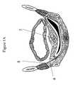
- FIGS. 1A and Bdepict generically a soft tissue structure undergoing soft tissue reconstruction.
- FIG. 2depicts an embodiment of the present systems and methods used for Nissen fundoplication.
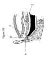
- FIG. 3shows an embodiment of a fixation device according to the present invention.
- FIGS. 4A–Cdepict embodiments of fixation devices according to the present invention.
- FIGS. 5A and Bdepict embodiments of fixation devices according to the present invention.
- FIGS. 6A and Bdepict embodiments of fixation devices according to the present invention.
- FIGS. 7A and Bdepict embodiments of fixation devices according to the present invention.
- FIGS. 8A–Cdepict embodiments of fixation devices according to the present invention.
- FIGS. 9A–Cdepict embodiments of fixation devices according to the present invention.
- FIGS. 10A–Cdepict embodiments of fixation devices according to the present invention.
- FIGS. 11A and Bdepict embodiments of fixation devices according to the present invention.
- FIGS. 12A and Bshow schematically the anatomical basis for a paravaginal repair of a pelvic floor defect.
- FIGS. 13A–Gshow schematically a repair of a soft tissue defect according to the systems and methods of the present invention.
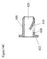
- FIGS. 14A–Gshow in more detail embodiments of fixation systems and devices useful for the methods of the present invention.
- FIGS. 15A–Dshow in more detail embodiments of fixation systems and devices useful for the methods of the present invention.
- FIGS. 16A and Bdepict embodiments of fixation devices according to the present invention.
- FIGS. 17A and Bdepict embodiments of fixation devices according to the present invention.
- FIG. 17Cdepicts an embodiment of a top side of a ratchet assembly according to the present invention.
- FIGS. 18A and Bdepict embodiments of fixation devices according to the present invention.
- FIGS. 19A and Bdepict embodiments of fixation devices according to the present invention.
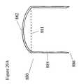
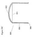
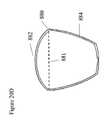
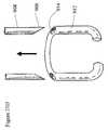
- FIGS. 20A–Ddepict embodiments of fixation devices according to the present invention.
- FIGS. 21A–Idepict embodiments of fixation devices according to the present invention.
- FIGS. 22A–Cdepict embodiments of fixation devices according to the present invention.
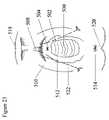
- FIG. 23shows a schematic anatomic diagram of the female perineum illustrating positioning of fixation devices according to one embodiment of the present invention.
- FIGS. 24A and Bshow embodiments of a template according to the present invention.
- FIG. 24Cshows an anatomic cross-sectional diagram of the female pelvis with a template positioned according to the systems and methods of the present invention.
- FIGS. 25A–C and FIG. 25Eshow embodiments of templates according to the present invention.
- FIG. 25Dshows an anatomic partial cross-sectional diagram of the female pelvis with a template positioned according to the systems and methods of the present invention.
- FIG. 26depicts an embodiment of a fixation device applicator.
- FIGS. 27A–Cdepict an embodiment of a fixation device applicator.
- soft tissue reconstructive surgeryrelates to those conditions characterized by abnormal positioning of normal tissues or characterized by tissue or anatomic abnormalities that result in malposition of anatomic organs or structures, or to those conditions wherein it is desirable for the patient's well-being to reposition or recontour a normally positioned soft tissue structure or organ.
- soft tissue reconstructive surgery or soft tissue reconstructionmay include the variety of suspensions, pexies and lifts performed in different anatomic regions.
- Soft tissue reconstructionmay also include a procedure like gastric stapling where the shape of the stomach is altered to treat morbid obesity.
- soft tissue reconstructionmay be applied to procedures like Nissen fundoplications where the normal anatomy of a soft tissue structure or an organ is altered in order to treat a functional or physiological abnormality.
- soft tissue structuremay refer to any identifiable tissue area, organ or organ component that is made of soft tissues.
- an identifiable area of thickened fascia, such as the conjoint tendonmay be called a soft tissue structure; similarly, a viscus, a body lumen, a muscle or other tissue areas, organs or organ components may be termed soft tissue structures.
- ATFPwill be used to refer to the arcus tendineus fascia of the pelvis.
- the systems and methods of the present inventionrelate to the coaptation of intact soft tissue structures. These are structures which have not been traumatized, incised or divided surgically.
- the present inventionmay be used to hold together two soft tissue structures by approximating their serosal surfaces.
- the present inventionmay be used to fix a soft tissue structure with an epidermal or mucosal external surface to a deeper soft tissue structure, so that the distal end of the fixation device is buried in the deeper soft tissue.
- fixation devices according to the present inventionare advantageously adapted so that they can secure a superficial tissue to a deeper tissue without requiring that the surgeon access the deeper tissue or access a surface on the distal aspect of the deeper tissue to position the fixation device properly or to affix it in position.
- the entire fixation devicemay be buried in the soft tissues.
- the proximal end of the fixation devicemay be visible or palpable on an external aspect of a soft tissue.
- the fixation devicesas exemplified herein, may be adapted for particular anatomic uses, so that their proximity to adjacent structures does not damage the structure, or does not cause the patient pain or discomfort.
- an affixation devicemay be made of biocompatible, biodegradable materials whose local presence stimulates tissue ingrowth and wound healing processes, thereby forming scar tissue.
- an affixation devicemay be coated with materials that would encourage tissue ingrowth or that would stimulate scarring or epithelialization. Positioning the affixation devices may of itself induce some local tissue trauma that will stimulate reparative processes such as wound healing. This may take place by local irritation or by the presence of a material or a surface treatment on the device that stimulates collagen deposition or inflammation with subsequent scar tissue formation.
- the tensile strength produced by local reparative processesmay, in certain embodiments, complement the tensile strength produced by the adherence of the fixation device in the soft tissue structures. In other embodiments, however, the fixation device itself, multiply or singly applied, will grasp the tissues with sufficient force and durability to hold the soft tissues in their preselected position. General principles of surgical judgment will guide the practitioner in determining the number of fixation devices to use for a particular application, and in determining their optimal insertion sites. In certain embodiments of the systems and methods of the present invention, templates may be provided that will guide the placement of the fixation devices into anatomically correct areas. Examples of templates will be illustrated below.
- Templatesmay further be used diagnostically, so that the positioning of a template within the vaginal vault in the office may replicate the tissue positioning that would be performed during a soft tissue reconstructive procedure.
- the positioning of the templatemay serve to reduce the defect to its anatomic position, and may thereby confirm the diagnosis of the underlying anatomic condition, and furthermore may justify operative intervention using the systems and methods disclosed herein.
- various diagnostic modalitiesmay be used to identify the anatomic structures and tissues into which or through which a fixation device is to be inserted.
- Representative diagnostic modalitiesinclude MRI, fluoroscopy, CT scan, conventional radiology, ultrasound, laparoscopy and endoscopy, although other modalities may be or may become apparent to practitioners of ordinary skill in the art.
- various modalitiesmay be used to guide the placement of a fixation device through and into the appropriate anatomic structures.
- Representative modalitiesinclude MRI, fluoroscopy, CT scan, conventional radiology, ultrasound, laparoscopy and endoscopy, direct visualization (for example through a vaginal speculum or through an open laparotomy incision), and intraoperative palpation, through a pre-formed surgical incision or through an incision created specifically to admit the surgeon's palpating finger or hand. Appropriate guiding modalities will be evident to surgical practitioners, based on the anatomic area under consideration.
- FIG. 1Adepicts generally a generic defect, corresponding to no specific anatomic region, appropriate for repair according to these systems and methods.
- the soft tissue structures being coaptedare in contiguity with each other in the native anatomic state.
- contiguityrefers to physical proximity, including adjacency.
- the native anatomic stateis understood to be the natural anatomic position.
- tissues that have been moved, either traumatically or iatrogenically to a different position than the natural anatomic oneare not considered to be in the native anatomic state.
- a congenital anomaly producing a malposition of a soft tissue structureshall be understood to involve tissues not in their native anatomic state.
- FIG. 1Ashows a ptotic structure 2 which has assumed an abnormal position due to the laxity of the lax tissue 4 which is intended to support the structure 2 . Because of the attenuation, stretching or damage to the lax tissue 4 , the ptotic structure 2 rests in an abnormal position which leads to its physiological dysfunction.
- the ptotic structure 2may be a conduit or body lumen like the urethra or the rectum; in these cases, the physiological function being disrupted may be the normal passage of body fluids or the subject's control over the passage of body fluids. In another example, the ptotic structure 2 .
- FIG. 1Afurther shows a supportive tissue 8 identified by the surgeon as a stable structure or anatomic region with sufficient strength to permit the lax tissue 4 to be coapted thereto, thereby to support the ptotic structure 2 .
- FIG. 1Bshows an embodiment of the present invention wherein the structure 2 , formerly ptotic, has now been supported by a pexy or a plication of the previously lax tissue 4 through the placement of a fixation device 10 that is inserted through the lax tissue 4 into the supportive tissue 8 .
- FIGS. 1A and Bmay relate to any body area where a structure 2 has assumed an anatomically abnormal position.
- the lax tissue 4may be approached using conventional open surgical methods, or endoscopic methods or transmucosal or transcutaneous methods.
- the fixation devicemay assume a plurality of shapes, adapted for insertion in a specific tissue.
- the present inventionrelates to those systems and methods used for holding intact soft tissue structures together. In one embodiment, these systems and methods may be used to suspend one tissue from another, thereby to support the first tissue and further to support structures in anatomic and physiologic relation thereto.
- a structure in anatomic relation to another structuremay be one where the first structure is in proximity to or in continuity with the second structure, or where a force applied to the first structure is transmitted to the second structure, to affect its shape or position.
- a structure in physiologic relation to another structuremay be one where the physical relation of the first structure to the second is important for the normal physiological functioning of said second structure.
- the soft tissue structures that are coapted according to these systems and methodsmay rely upon a fixation device that is inserted from a first anatomic soft tissue structure to a second anatomic soft tissue structure.
- the fixation deviceis contained within each soft tissue structure, either wholly or partially residing within both soft tissue structures.
- a fixation device according to these systems and methodsneed not reside fully within either soft tissue structure. For example, a part of it may be external to one or the other soft tissue structure, or a part may reside within a third or a fourth soft tissue structure.
- a fixation devicemay be coated with agents or provided with surfaces intended to promote epithelial overgrowth of the device. As examples, coatings with collagen, growth factors or adhesion ligands may be provided. As further examples, the surface of the fixation device may be textured or roughened to provide a platform for epithelialization.
- FIG. 2shows schematically the use of soft tissue fixation devices according to these systems and methods to perform an approximation of intact tissues for a soft tissue reconstruction of an anatomic abnormality leading to esophageal reflux.
- a Nissen fundoplicationis schematically represented.
- the figureshows a defect 20 in the diaphragm 22 representing a hiatal hernia, an anatomic defect responsible for esophageal reflux.
- a Nissen fundoplicationhas been performed, as is familiar to surgical practitioners.
- the figureshows that the proximal gastric fundus 28 has been wrapped around the stomach 32 and esophagus 24 at the level of the gastroesophageal junction 30 , and the fundus 28 has been fixed to itself.
- fixation devices 34has been used to accomplish the fixation of the intact gastric fundus 28 to the anterior wall of the stomach 32 , thereby resisting the pathophysiological abnormalities accompanying symptomatic hiatal hernia.
- Fixation devices useful for this proceduremay be designed to approximate the intact structures gently, so that their blood supplies are not compromised, and so that their intact edges are not subject to pressure necrosis.
- Fixation devices useful for this proceduremay be made of any biocompatible material, although the use of metallics for abdominal surgical fixation is well-known and well established in the art.
- Fixation devices useful for this procedurefurthermore may be designed not to penetrate the full thickness of the stomach, but rather to reside within the muscle layer, so that the passages within which the fixation devices are located do not provide portals of entry for gastric juices and bacterial contamination. Shapes suitable for this and other procedures may be selected according to these anatomical needs. Embodiments of suitable fixation devices are described below. Other appropriate modifications will be readily envisioned by practitioners of ordinary skill in the relevant arts.
- fixation devicesmay be provided to show the operator the preferred placement of the fixation devices.
- application of fixation devices for soft tissue reconstructioncan be guided by other surgical methods, such as palpation of landmarks through a small incision, or such as laparoscopic or endoscopic visualization.
- Other modalitiessuch as fluoroscopy, CT scan, MRI or other radiological methods, may be employed for guiding the surgeon in positioning the fixation devices.
- fixation devicesthat can be readily extracted from tissues in case it needs to be repositioned or removed entirely.
- Fixation devices that are malpositionedmay need to be repositioned.
- Fixation devices that are unsuccessful or are causing symptoms by their presencemay need to be removed. Since the fixation devices according to the present invention are inserted into intact tissues, it is desirable that their removal will be accomplished without undue trauma to the approximated tissues.
- the process of implanting and removing fixation devicesinvolves generally a manipulation of the devices, which may take place manually by the operator, or may take place by using a tool. Fixation devices are both implanted and removed by a manipulation.
- fixation devicesmay be contemplated that are appropriate for various anatomic areas. Certain embodiments are presented below that demonstrate these and other features, although the depicted embodiments are understood to be illustrative only. Other modifications will be readily envisioned by practitioners of ordinary skill in the art, said modifications to fall within the scope of the present invention as disclosed herein.
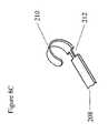
- a fixation device 740is shown that may be placed vaginally or laparoscopically using an insertion device to perform a paravaginal repair, reapproximating the superior lateral sulci to the ATFP according to the systems and methods of this invention. Furthermore, the depicted embodiment may be used for fixation of other soft tissues, according to systems and methods disclosed herein.
- the depicted fixation device 740is formed with a horizontal bar 744 with a vertical arm 742 at each end forming substantially a right angle to the bar 744 .
- the distal end 752 of each vertical arm 742bears a barb 748 with a distalmost insertion point 750 .
- the barb 748includes a proximally oriented member 754 that may hook into the tissues and anchor the fixation device 740 in the appropriate anatomic site. While the illustrated embodiment is drawn to show the members of the fixation device 740 in a fixed relationship to each other, a number of modifications may be readily envisioned by practitioners of ordinary skill whereby the barbs 748 may be flexible or may change in their relationship to the vertical arm 742 . Other modifications for barbed fixation devices according to these systems and methods have been disclosed in certain preceding figures. As will be apparent to practitioners of ordinary skill in these arts, the modifications introduced for fixation devices as described above can be readily applied to fixation devices adapted for intravaginal use.
- the horizontal bar 744 of the fixation device 740could be made of an absorbable (such as polyglycolic acid or polydioxone) or nonabsorbable material.
- the surface of the devicecould be formed or coated to encourage reepithelialization by the vaginal mucosa as described above.
- the fixation device 740can be inserted by an applicator either across intact epithelium or through an insertion incision. If an insertion incision is made, tissue elasticity and wound healing may combine to re-form an intact epithelial covering over the fixation device.
- FIG. 3other embodiments, illustrated below, may be readily adapted for use in this anatomic area. Modifications of the depicted embodiments may be undertaken by those of ordinary skill in the art, said modifications being encompassed by the scope of the present invention.
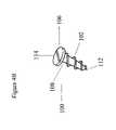
- FIGS. 4A–Cshows several embodiments of fixation devices configured as screws.
- FIGS. 4A and Bdepict a screw 100 sized for a particular anatomic region wherein it will be positioned to grasp an intact tissue.
- the depicted embodimentcomprises a shaft 108 with screw threads 102 disposed thereupon and an insertion point 112 , so that the screw 100 can penetrate a first tissue and obtain purchase in a second tissue, thereby to fix the two together.
- FIG. 4Ashows a rounded head 104 on the screw 100 .
- FIG. 4Bshows a flat head 106 on the screw. Head shapes and sizes may be selected for particular anatomic areas.
- a screw 100may be inserted into the tissue using a tool adapted for this purpose.
- FIG. 4A and Bdepict a screw 100 sized for a particular anatomic region wherein it will be positioned to grasp an intact tissue.
- the depicted embodimentcomprises a shaft 108 with screw threads 102 disposed thereupon and an insertion point 112
- the screw head 104has a circumferential row of ridges 116 that can engage an insertion tool.
- the screw head 106has a driving slot 114 that can accept a tool configured like a screwdriver.
- FIG. 4Ca screw 100 with a set of circumferential barbs 110 intended to engage tissue as they are pushed in. The insertion point 112 permits the screw 100 to penetrate the tissue, and the circumferential barbs hold the tissue as the screw 100 is progressively pushed deeper.
- Screws 100may be fabricated of various materials, depending upon the anatomic area in which they are to be used. They may be made of metallics, ceramics, polymers or other materials, for example.
- the screw headmay be countersunk through an incision that is formed to allow the screw head to sink below the overlying epithelium, so that the screw head is buried and covered with epithelium. This countersinking may similarly be applied to proximal portions of other fixation devices, such as certain embodiments described or depicted below.
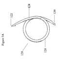
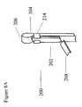
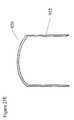
- FIG. 5Ashows an embodiment of a screw shaped as a coil 120 that can be used for tissue fixation according to these systems and methods.
- an insertion point 122is adapted for penetrating the tissues to allow the flexible member 124 to be inserted therein.
- a screwing motionmay be used to engage the anchoring tissues, or a motion similar to that used to insert a curved needle bearing a suture.
- the insertion point 122is directed distally through the anchoring tissue and then is redirected proximally, to be grasped by the operator.
- the curve 128 of the coil 120is shaped to facilitate the encircling of the target tissue.
- the insertion point 122may be inserted into the latch 130 at the proximal end of the coil 120 . As shown in FIG. 5B , this forms an outer ring 132 around an inner ring 134 , with the target tissue 128 within these rings. To remove the device, the outer ring 132 can be disarticulated by removing the insertion point 122 from the latch 130 , and then backing the coil out through the target tissue 138 .
- Embodiments using the coil shape or modifications thereofmay advantageously use flexible materials, whether metallic or polymeric. In certain embodiments, shape memory alloys may be used to achieve configurations such as those depicted in these figures, as will be readily apparent to artisans of ordinary skill in the art.
- shape memory alloySMA
- SIMstress-induced martensite
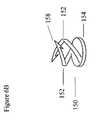
- FIG. 6Ashows a screw 150 with a single arm 152 extending distally from a base coil 154 that supports it.
- An insertion point 158is available to penetrate the tissues as the screw 150 is inserted.
- a barb 160anchors the screw 150 into the anchoring tissue, while the base coil 154 exerts pressure on the proximal tissue to affix it to the anchoring tissue.
- FIG. 6Ba screw 150 is seen with a double arm 152 design, one arm being placed posterior to the other and both affixed to an anchoring coil 154 .
- the arms 152are made from flexible materials so that they can be manipulated so as to attain purchase on the correct anchoring tissue. Materials suitable for the screws 150 depicted in these figures may include metallics, polymers, ceramics or other materials adapted for a particular anatomic region. Furthermore, the screw 150 may be absorbable in whole or in part.
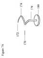
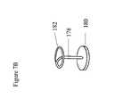
- FIG. 7Ashows a screw 170 comprising a coil 174 extending outward from a shaft 178 , the shaft 178 being affixed to a support plate 180 .
- An insertion point 172is available for penetrating the outer layer of tissues.
- a SMA or a SIMmay be used to form the coil 174 , so that after insertion the coil 174 closes itself upon itself to form a ring 182 , as shown in FIG. 7B .
- the ring 182is formed after the screw 170 has been positioned within the appropriate tissue. When the ring 182 forms, it serves to encompass the insertion point 172 so that the insertion point 172 does not continue to penetrate tissues.
- the support plate 180puts pressure on the first layer of tissues to allow them to be held in approximation to a second layer of tissues within which the ring 182 has formed.
- FIGS. 8A–Cshow an anchor system 200 for insertion into tissues to affix one tissue to another.
- the term anchorrefers to a structure wherein outwardly arranged arms are available to engage a target tissue.
- FIG. 8Ashows an anchor member 202 held in a carrier 204 which is configured to hold the anchor member 202 substantially straight.
- the anchor member 202may be originally formed to curve back upon itself, but may be straightened out by the carrier 204 .
- the anchor member 202may be formed in whole or in part of an elastic material to permit this to occur.
- the distal point 206 of the carrier 204may be sharpened to permit insertion from a first tissue into a second.
- the carrier 204may be pulled proximally on the anchor member 202 , allowing the anchor member 202 to assume its original curved shape 210 , as shown in FIGS. 8B and 8C .
- the carrier 204may be removed entirely from the anchor member 202 when its tabbed arms 214 reach the removal notch 212 on the anchor member 202 .
- the carrier 204may be left attached to the anchor member 202 so that by directing the carrier 204 distally on the anchor member 202 , the anchor member 202 may be straightened out within the tissues and the anchor system 200 can be removed from the tissues.
- the proximal end 208 of the anchor systemmay be fitted with any sort of head or other securing device that will affix or embed the proximal end of the anchor member 202 within the first tissue layer.
- FIG. 9Ashows an embodiment of an anchor 220 with a distal insertion point 230 adapted to penetrate a first tissue to arrive in a second tissue.
- a set of arms 222are shown folded or collapsed axially around a central shaft 224 .
- the collapsed arms 222can be directed outward into an anchoring position 232 , as shown in FIG. 9B .
- the adjustable base 226may then be positioned on the shaft 224 to provide the appropriate compressive force pushing the first tissue towards the second. Once the adjustable base 226 has been compressed sufficiently, it will lock into one of the circumferential grooves 228 circumscribing the shaft 224 .
- a protruding part 234 of the shaft 224may be trimmed or cut flush with the base 226 .
- a view of the top of an anchor 220a plurality of arms 236 may be arranged according to various designs to grasp particular tissues with optimal tenacity.
- the structures depicted in these figuresmay be made of non-absorbable materials or of materials wholly or partially absorbable. In particular, where pointed areas are shown in these and other figures, it may be desirable to form the points from absorbable materials so that they do not present to the patient a long-term sharp edge.
- FIGS. 10A–Cdepict embodiments of tissue anchors that are directed to open from an initially closed position by the use of muscle wire.
- muscle wirerelates to a type of memory wire or SMA, commonly a titanium nickel alloy, that returns to a preset shape at a preset transition temperature. At the preset temperature the wire contracts in length a determined amount. In certain forms, the amount of muscle wire contraction at the transition temperature is about 3–5%. The force exerted by this contraction can be very powerful.
- the muscle wirehas a “programmed” temperature at which it has a “programmed” shape. When the wire cools, it goes back to a non-programmed shape. As the wire is heated, it tries to return to its programmed shape.
- the wirehas two possible states. There is the cooled state (temperature) at which the wire can be stretched, and the programmed state (temperature) at which the wire returns to its programmed length.
- the wireAt the programmed state, the wire exhibits a crystalline structure known as austenite.
- martensitewhich is a herringbone shaped crystal lattice.
- the martensiteis much more flexible than the austenite, allowing the cooled wire to expand.
- the structureWhen the wire is heated to its transformation temperature, the structure reverts to austenite and the wire contracts.
- the wireis much more susceptible to stress, and thus is more easily damaged.
- a muscle wire 260is embedded in an anchor 262 , running through the shaft 264 across a flexible joint 266 to attach to the proximal portion 272 of the anchoring arm 276 .
- An insertion point 270is provided whereby the anchor 260 in its collapsed state can be inserted into the target tissue.
- the proximal part 274 of the anchor 260may be fitted with any fastening structure allowing it to engage and become implanted in the first tissue through which the anchor passes, while the anchoring arm 276 is adapted for lodging within the second, anchoring tissue.
- FIG. 10Bshows a cross-section of the shaft 264 taken at a line A–A′ on FIG. 10A .
- FIG. 10Bshows a muscle wire 260 may be seen partially embedded in the shaft 264 .
- FIG. 10Cshows the effect of contraction of the muscle wire 260 : the muscle wire 260 has shortened and exerted tension on the proximal end 272 of the anchoring arm 276 . This tension has forced the anchoring arm 276 outward from its initial contracted position, so that its distal end 268 engages the surrounding tissues.
- the muscle wire 260may also exert tension on the proximal end 274 of the anchor 260 , where a fastening structure has been placed.
- This tension on the proximal end 274 and its affixed fastenermay serve further to compress the two tissues whose coaptation is desired.
- the insertion point 270may be made from an absorbable material so that the point does not remain in the tissues, potentially damaging them.
- the distal end 268 of the anchoring arm 276is shown here to be rounded, although other shapes can be envisioned by skilled artisans in the field.
- FIGS. 11A and Btakes advantage of the fact that certain polymers, well-known in the art, are biocompatible and water-soluble.
- an anchor system 300is shown with a proximal end 304 , a shaft 302 and a spring-loaded anchoring arm 306 .
- FIG. 11Ashows the anchoring arm 306 bent against the shaft 302 in a closed position.
- the anchoring arm 306is held in this closed position by a water-soluble polymeric lock 308 inserted in a tongue-in-groove configuration 310 in the outer aspect of a joint 314 between the shaft 302 and the anchoring arm 306 .
- the spring-loaded anchoring arm 306is thus held in the closed position by the presence of the polymeric lock 308 . While a tongue-in-groove lock shape 310 is shown in the depicted embodiment, it is understood that any lock mechanism that uses the water-soluble polymer to block the outward motion of the spring-loaded anchoring arm 306 may be suitable for use in this system.
- the polymeric lock 308is also equipped with an insertion point 312 that may provide a leading edge for the anchoring system 300 to penetrate the tissues.
- FIG. 11Bwhen the water-soluble polymeric lock dissolves, the force resisting the outward spring of the spring-loaded anchoring arm 306 is removed and the anchoring arm 306 springs outward. In the position depicted in FIG. 11B , the anchoring arm 306 may engage the tissues, thereby seating the anchoring system 300 .
- the proximal end 304 of the anchoring system 300may be fitted with any appropriate fastener to seat or embed it in the most proximal tissues.
- FIGS. 12–14show an embodiment of an anchoring system, here illustrated with particular reference to soft tissue reconstruction of the female pelvic floor. While the use of this embodiment will be illustrated with reference to this anatomic location, it is understood that other anatomic applications will be readily apparent to those of ordinary skill in the art.
- FIGS. 12A and Bshow schematically how soft tissue reconstruction may be employed to treat laxity of the female pelvic floor.
- FIG. 12Ashows a laxity of the anterior wall 352 of the vaginal vault 350 being repaired by a fixation of the lateral sulci 356 of the vagina to the ATFP 354 . Any fixation device may be used to accomplish this, including sutures, as are well-known in the art.
- FIGS. 13 and 14show an embodiment of a fixation system adapted for soft tissue reconstruction.
- the fixation system depicted hereinis characterized by adjustable tension and by precision placement, making it suitable for use in vaginal surgery and in other forms of soft tissue reconstruction.
- the schematic depictions of these figuresindicate a feature of the systems and methods of the present operation, wherein a surgical incision is not created to expose the anchoring tissues.
- the term “expose”relates to a surgical process well-understood by practitioners whereby a particular tissue is approached by an incision of adequate size to permit the tissue to be identified and dissected free, substantially under direct vision. Incisions used for exposure understood to be significantly larger than an incision intended to provide laparoscopic or palpation access to the same structure.
- a laparoscopemay be used to visualize the defect and to visualize the intended anchoring structure for the repair.
- a fixation devicemay still be inserted through the vagina into the lateral sulci to attain fixation in the ATFP.
- a laparoscopemay also be inserted into the Space of Retzius using laparoscopic techniques well known in the art. By advancing the laparoscope, the defect requiring soft tissue reconstruction may be visualized, and the supporting structures may be identified. While this example relates to pelvic floor reconstruction, it is understood that laparoscopic or other forms of anatomic guidance may be employed within the scope of the present invention.
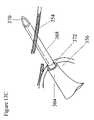
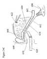
- FIG. 13Ashows an applicator 364 being inserted into the vaginal vault 350 to deliver a fixation device into the lateral sulcus 365 in order to affix this structure to the ATFP 354 , thereby suspending the anterior wall 352 of the vagina.
- FIG. 13Bshows in more detail the distal end 374 of the delivery device 364 .
- a hollow needle 386is situated on the distal end 374 of the delivery device 364 , permitting delivery of fixation devices into the intended anatomic location.
- a penetrating tip 370is located at the distalmost end of the needle so that tissues can be pierced to allow access thereto for the fixation devices.
- FIG. 13Cshows the fixation device 364 directing the needle 368 through the wall of the lateral vaginal sulcus 356 and further through the ATFP 354 .
- the penetrating tip 370has been directed into the ATFP or just distal thereto, to permit placement of the fixation device so that it will be anchored in the ATFP.
- FIG. 13Dshows a fixation device, here a toggle 378 , being directed into the tissues comprising or adjacent to the ATFP.
- the toggle 378passes through the hollow needle 368 to enter the tissues.
- the toggleis equipped with a swivel mechanism 380 , shown in more detail in FIGS. 14D and E.
- a swivel mechanism 380shown in more detail in FIGS. 14D and E.
- the toggle 378swivels into a position normal to the longitudinal axis of the needle and remains in the ATFP 354 .
- the microporous bolster 372abuts against the wall of the lateral sulcus 356 .
- a connector 382is provided that is attached distally to the toggle 378 and that passes through or into the bolster proximally.
- the connector 382may be a set of sutures or a polymeric connecting member or any other elongate structure that can be attached to the toggle 378 and further can be pulled proximally by the operator.
- the connector 382may be pulled proximally through or into the bolster 356 after the needle is removed.
- the connector 382exerts tension on the toggle 378 and advances the bolster 372 towards the ATFP 354 .
- the connector 382permits the operator to set the desired tension on the repair. When desired tension is achieved, the connector 382 is set. This may be accomplished by tying down the connector 382 , as with sutures for example, or by attaching the connector 382 to the bolster 372 at an appropriate place so that constant tension is maintained.
- FIG. 13Gshows the proximal end of the bolster 372 , as seen from the vagina. The end 384 of the connector has been secured in the bolster 372 and has been cut so that it does not protrude into the vagina.
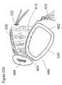
- FIGS. 14A–Gshow in more detail features and modifications of the system illustrated in FIGS. 13A–G .
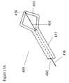
- FIG. 14Ashows a disposable unit 400 adapted for use with a disposable or reusable applicator handle (not shown).
- an adapter cylinder 402can be inserted within the applicator handle and can receive the plunger or other mechanism from the applicator that directs the toggle 410 outward through the needle shaft 412 to lodge in the tissues.
- a bolster 408is shown along with a single toggle 410 in the depicted embodiment.
- the disposable unit 400can equally be equipped with a multiple dispensing cartridge of toggles carried within it, accompanied by an associated stack of bolsters. As depicted in FIG.
- FIG. 14Ashows an embodiment of a bolster 408 , wherein a flap lock 418 is provided so that the connector (not shown) can be secured after tension on the toggle is set.
- FIG. 14Cshows a cross-section of the toggle 408 taken at line B–B′ drawn on FIG. 14B .
- FIG. 14Cshows a flap valve 418 , here directed inward to catch on a notch of the connector.
- the flap valve 418could equally well be outwardly directed to catch on a notch of the connector as the connector is pulled through the flap valve 418 and thus through the lateral wall 424 of the bolster.
- This figurefurther shows a lumen 420 passing through the bolster, although other designs could be readily envisioned by skilled artisans in the field.
- the figurealso shows a flared proximal end 422 adapted to abut against the mucosa of the vaginal wall. Again, other embodiments of the proximal end could be readily envisioned by those of ordinary skill in the art.
- the proximal end 422may be modified, either to permit absorption by the body, or tissue incorporation or epithelialization.
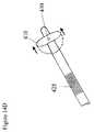
- FIG. 14Dshows in more detail the swivel mechanism that permits the toggle 410 to pivot from an axial orientation to an orientation normal to the long axis of the delivery device.
- a pivot 430is provided in the mid-portion of the toggle 410 that permits it to swivel on that axis.
- the pivot 430also connects the toggle 410 to the connector 428 , as shown in FIG. 14E .
- FIG. 14Eshows in more detail the swivel mechanism that permits the toggle 410 to pivot from an axial orientation to an orientation normal to the long axis of the delivery device.
- a pivot 430is provided in the mid-portion of the toggle 410 that permits it to swivel on that axis.
- the pivot 430also connects the toggle 410 to the connector 428 , as shown in FIG. 14E .
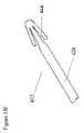
- FIG. 14Fpresents an alternate embodiment for tissue fixation, where a fixation device 432 is equipped with folding arms 444 that are folded in a closed position when the device 432 is loaded in a cylindrical delivery device (not shown)
- a fixation device 432When the target tissue is reached by the delivery device, it is withdrawn, leaving the fixation device 432 in place.
- the armsassume an extended position 448 , as shown in FIG. 14G .
- the force urging the arms outwardmay be an elastic force provided by the material from which the arms are made, or it may be a force produced by a SMA, or it may be any other force that is recognized in the relevant arts.
- FIGS. 15A–Dshow an alternate embodiment of a fixation device 450 adapted for positioning in a soft tissue, and further adapted for ready removal.
- a fixation device 450is shown, comprising an expandable end 454 to the distal end 458 of which is affixed a pull wire 456 or a monofilament suture.
- the pull wire 456passes through the hollow shaft 542 of the fixation device 450 to emerge through the proximal end 460 .
- the proximal end 460is adapted to be used with a bolster, as seen in FIG. 15D .
- To insert the fixation device 450it is placed within a delivery device that includes a distal needle 464 .
- FIG. 15Cshows the needle 464 having penetrated an anchoring tissue 466 .
- the expandable end 454assumes its expanded contour.
- FIG. 15DA proximal pull on the pull wire 456 will deform the expandable end 454 so that it assumes a mushroom shape 468 or some other shape intended to affix it in the tissues.
- the expandable end 454is held in this mushroom shape 468 by continuous traction on the pull wire 456 .
- tensionis applied to the pull wire 456 and the pull wire 456 is inserted through the bolster 462 and affixed thereto to provide constant tension.
- the pull wire 456may be cut or disengaged, permitting the expandable end to revert from the mushroom shape 468 to its previous shape. Applying traction to the flexible expandable end 454 may permit its ready detachment from the tissues in which it has been embedded.
- FIGS. 16A and BAn embodiment permitting tension adjustment and ready release is depicted in FIGS. 16A and B.
- This embodimentshows two tissue fixation devices 802 connected by a flexible connector 804 .
- Each tissue fixation device 802is embedded in the target tissue and is anchored therein with the barb 800 .
- the tension on the flexible connector 804is then adjusted to the operator's specification.
- FIG. 16Ba modification is shown wherein the flexible connector 804 passes through a connector lock 806 on the end of at least one tissue fixation device 802 .
- the connector lock 806permits varying tension to be applied to the connector 804 by proximally directed traction on its proximal end 804 .
- the connector lockmay be configured like the “quick releases” for backpack straps, wherein the straps are locked by threading them through an assembly that changes their direction, and wherein straps can be quickly released by manipulating the assembly.
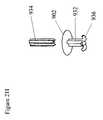
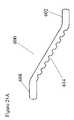
- FIGS. 17A and Bshow a ratcheting assembly 810 to permit tension adjustment on a tissue fixation device.
- the tissue fixation devicewill be inserted from one side of the tissues only, and its distal end will reside wholly or in part within the target tissue, so that the distal end is not accessible for manipulation or for attaching to other components.
- a ratcheting systemaccording to these systems and methods therefore is desirably configured so that it applies its ratcheting compression from one side only, preferably the proximal side.
- two arms 812are provided for insertion into the tissues.
- Each arm 812is comprised of a shaft 820 bearing a series of ratchet teeth 814 .
- each arm 812passes through a channel 822 in a horizontal affixation member 824 .
- the arm 812may pass completely through this channel 822 to exit the proximal side of the affixation member 824 .
- Within the channelis a set of ratchet teeth 826 shaped to interdigitate with the ratchet teeth 814 on the arm 812 .
- the ratcheting assembly 810can be driven through a first tissue into a second tissue, with the insertion points 818 of the device entering the second tissue.
- the affixation member 824which has remained external to the first tissue may be ratcheted down on the arms 812 to apply coapting tension between the first and the second tissues.
- FIG. 17Bdepicts a ratcheting assembly 810 wherein the affixation member 824 has been snugged down on the arms 812 and any proximally protruding portion of the arms 812 has been removed. Barbs 816 are present in the depicted embodiment to grasp the anchoring tissue.
- FIG. 17Cdepicts a top side of a ratchet assembly 810 showing the arms 812 passing through the affixation member 824 . In the depicted embodiment, the arms 812 have been trimmed so that they do not protrude from the affixation member 824 .
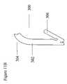
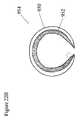
- FIG. 18Ashows a ring shaped fixation device 830 adapted for easy removal from tissues even after it has been securely inserted.
- An insertion point 832is provided to permit penetration of target tissues.
- a barb 834is provided in the depicted embodiment to engage the tissues and prevent backsliding as the fixation device 830 is urged forward.
- a locking channel 836is shaped to receive the insertion point and to secure this and the barb within a passage interior to the device 830 . Once the point 832 and the barb 834 are fastened within the locking channel 836 , there are no sharp points directed externally to injure the patient. Rather, the tissues are held encircled by the closed loop 838 formed by the fixation device 830 , as shown in FIG. 18B .
- FIG. 18Ashows a ring shaped fixation device 830 adapted for easy removal from tissues even after it has been securely inserted.
- An insertion point 832is provided to permit penetration of target tissues.
- a barb 834is provided in the depict
- 18Afurther shows a seam 840 representing the place where the insertion point and the barb have entered the locking channel.
- directing force against this seammay permit the barbed end to become detached from the locking channel. If this takes place, the ringed fixation device may be readily freed from the tissues relatively atraumatically. Once the barbed end has been detached from the locking channel, the operator may continue to push the barbed end through the tissues until it exits. Further traction on the barbed end may free the fixation device from the tissues.
- FIGS. 19A and Bshow yet another embodiment of a fixation device 850 .
- two pincers 852are provided, attached to each other by a hinge and capable of rotating inwardly with the application of inward force.
- the insertion points 858 of the pincers 852penetrate and engage the tissue.
- a lock mechanism 856 located proximallycan be activated after the pincers have adequately engaged the target tissue.
- FIG. 19Bshows the pincers 852 of the fixation device 850 in a closed position to engage the target tissue therebetween.
- a lock mechanism 855may be activated to hold the pincers 852 in their closed position.
- FIGS. 20A–Ddepict embodiments where a shape memory alloy may be used to alter the shape of the fixation devices after heating.
- FIG. 20Ashows a fixation device 880 according to the present invention ready for insertion.
- a horizontal bar 882connects to a vertical arm 884 at each end.
- the dotted line 881indicates the width of the device at the level of the horizontal bar 882 .
- the vertical arms 884are attached to the horizontal bar 882 at substantially right angles.
- Each vertical arm 884is equipped with a penetrating end 886 dimensionally adapted for insertion through a first tissue into a second tissue.
- the entire vertical height of the fixation device 80may be approximately 13 mm.
- Each vertical arm 884is comprised of two segments, a proximal one about 8 mm in length and a distal one about 3 mm. in length.
- the length of the horizontal bar 882may be about 10 mm.
- the proximal segment of the vertical arm 884is bowed inward somewhat, while the distal segment of the vertical arm 884 bends on itself.
- FIGS. 20C and Dshow modifications of the same structure.
- FIG. 20Cshow a fixation device 880 adapted for insertion into intact tissues according to the systems and methods disclosed herein. Once the insertion points 86 have entered the target tissue, then heat may be applied to the device 800 . The application of heat may cause the fixation device 800 to bow in the distal part of its arms 884 and the distal part of the penetrating edge 888 , as seen in FIG. 20D .
- FIG. 20Dshows the penetrating ends 886 of the vertical arms 884 to be nearly touching, and further shows a smoother configuration with fewer angulated edges than the device shown in FIG. 20B .
- FIG. 21Ashows a hollow fixation device 900 that is inserted into the tissues by being carried on an introducer pin 904 with a sharpened insertion point 908 .
- a proximal seat 902is depicted that allows the fixation device 900 to apply pressure on proximal tissues, thereby to approximate them to distal tissues.
- the introducer pin 904may be removed, permitting the hollow fixation device to assume its natural curve 906 .
- the curvemay be imparted to the hollow fixation device 900 by selecting a flexible material that can be shaped into a curve and that can tolerate being straightened temporarily by the introducer pin 904 .
- Other materialssuch as SMA, may be used, as well as those materials that will be apparent to ordinary skilled practitioners.
- 21 C and Dshow an arrangement where two fixation devices 900 are joined together by a horizontal bar 910 . Introducer pins 904 are inserted into each arm 912 of the fixation device, thereby straightening each arm. When the fixation device 900 is properly inserted into the target tissue, the introducer pins 904 may be removed, permitting the device to assume a curved position.
- FIGS. 21E–Gfiguratively depict an embodiment where a fixation device 920 is made of a material that exhibits a two-way shape memory affect. When inserted into tissue at body temperature, the fixation device 920 may take on a particular shape, as shown in FIGS. 21F and G. These shapes show the arms 912 having assumed a bent or a closed position, thereby encircling tissues.
- a staplemay be any structure wherein the arms angulate inward with the application of a force (including a force intrinsic to the device itself, such as the change in shape that occurs in a SMA with heating or cooling), so that the arms encircle the designated tissue.
- a forceincluding a force intrinsic to the device itself, such as the change in shape that occurs in a SMA with heating or cooling
- FIGS. 21H and Ishow an embodiment of a fixation device 930 comprised of a plurality of hollow tubes 932 that each contain an introducer pin while the device 930 is inserted into body tissues.
- the introducer pins 934may be removed, allowing the hollow tubes 932 to revert to their naturally curved state 932 .
- a variety of materialsmay be used to fabricate the hollow tubes 932 , including polymers and metallics, particularly those comprising shape memory alloys.
- a shape memory activatoris a laminate comprising a spring 950 and a shape memory element 952 .
- the shape memory elementmay be formed to hold a certain shape at a warm temperature, as shown in FIG. 22B , where the memorized shape is curved when the structure is warm and the inwardly curving force of the SMA element 952 overpowers the externally located spring 950 .
- the spring 950can overcome the force exerted by the SMA element 952 .
- a fixation devicecan be used to perform a procedure for repairing lax soft tissues in the female pelvis.
- these systems and methodsmay be used to simplify the surgery required for performing a paravaginal cystocele repair and thereby to eliminate many of the complications of traditional reconstructive surgery.
- FIG. 23depicts a schematic anatomic representation of a gynecological view of the female perineum, illustrating places where fixation devices could be inserted according to these systems and methods to effect a paravaginal repair.
- anatomic landmarksare provided for orientation: the urethra 504 located posterior to the clitoris 508 between the labia majora 510 , and the anus 514 positioned posteriorly.
- the mons pubis 518indicates the anterior boundary of the region, and the intergluteal fold 520 indicates the posterior edge.
- the lips of the labia minora 512have been displaced by lateral traction to render more visible the more medial anatomic features.
- a large cystocele 500is shown, being visualized through the introitus 502 of the vagina.
- adequate anesthesiais induced, either general, regional or local, and appropriate prepping and draping is carried out.
- the fascial arcus or arcus tendineus fascia pelvis (ATFP)is identified by palpation.
- the ATFPis a condensation of fascia overlying the obturator internus and levator ani muscles, and can be found coursing between the posterior surface of the pubic bone and the ischial spine. With this knowledge, the location of the ATFP may be palpated through the vaginal mucosa. Once identified, the ATFP may provide the anchoring structure for the paravaginal cystocele repair. After the position of the ATFP has been identified by palpating it or otherwise identifying it, the tissues of the superior lateral sulci may be affixed thereto, along a line roughly indicated by 522 . The number of fixation devices applied will be determined by the surgeon using routine surgical judgment. In certain cases, between 4 to 8 fixation devices will be applied on each side. The placement of these fixation devices across the vaginal epithelium into the arcus tendineus will effect the suspension of the paravaginal tissues and thus will reduce the cystocele.
- fixation devicesmay include rectocele and vaginal vault prolapse repair. Since the most proximal portion of the ATFP is located near the ischial spine, a procedure according to these systems and methods may provide apical support for vaginal vault prolapse.
- the fixation devicesmay be applied to the sacrospinous ligament, which can also be palpated transvaginally, effecting vaginal vault suspension.
- fixation devices according to the inventionmay be applied to affix the inferior lateral sulci to the ATFP and/or the levator ani, depending upon the diagnosed anatomic defect.
- the systems and methods of the present inventionmay further include a template that facilitates accurate placement of the fixation devices.
- a templatemay be designed for each anatomic area to permit accurate placement.
- the templatemay be semi-flexible; thus permitting the template to be positioned over the proper area.
- the templatemay be placed between the ischial spine and the posterior pubic ramus, thereby defining the location of the arcus tendineous fascia pelvis, or fascial white line.
- a templatemay be formed as depicted in FIGS. 24A–C .
- FIG. 24Ashows a profile view of a template 600 adapted for insertion into the vagina, shaped with a proximal end 604 and a distal end 602 .
- a template 600When inserted, the contour of the template 600 follows the line the arcus tendineus fascia of the pelvis, as shown in FIG. 24C .
- a template 600is shown positioned within the vagina with its proximal end 604 situated anteriorly, in proximity to the pubic symphysis 608 .
- the distal end 602is positioned deep within the vagina and is oriented posteriorly towards the sacrum 606 .
- the template 600correctly positioned parallels the arcus tendineus 612 .
- the template 600is equipped with a set of grooves 614 or indentations along its inferior border.
- the grooves 614 in the template 600serve to guide the placement of soft tissue fixation devices 618 into the arcus tendineus 612 using an applicator device 620 as illustrated, or any other suitable applicator for the soft tissue fixation devices 618 .
- the advantages of the template 600include assisting the surgeon to properly insert and imbed the fixation devices 618 and further to avoid inadvertent placement of fixation devices into adjacent structures such as the obturator canal 622 .
- FIG. 24Bshows in more detail the configuration of a vaginal template 600 with a proximal end 604 and a distal end 602 and a set of grooves 614 along the inferior border serving to guide positioning of soft tissue fixation devices into the underlying anatomic structures.
- a template for pelvic floor reconstructive surgerymay be formed in a flatter design, as shown in FIGS. 25A–E .
- FIG. 25Aan embodiment of a template 600 is shown with a proximal end 604 and a distal end, adapted for positioning within the vagina.
- the lateral members 630may be slightly convex to coincide with the shape of the ATFP.
- FIG. 25Ashows an anterior projection of a template 600 .
- a sheet of material 632may be positioned to span the distance between the lateral members 630 .
- the sheet of material 632may be flexible or may be rigid with the capability for bending at a flexion point incorporated in the sheet of material 632 .
- the sheet of material 632may comprise a plurality of overlapping or interdigitating sheets to permit adjustment of the contour and size of the template 600 .
- FIGS. 25B and Cpresent perspective views of an embodiment of the template 600 , illustrating the contouring of its shape to match the contours of the vaginal vault wherein it is to be positioned.
- FIG. 25Dshows schematically a template 600 positioned within the vaginal vault, with the proximal end 604 situated in proximity to the pubic symphysis 608 and the distal end 602 positioned posteriorly, here in proximity to the sacrospinous ligament 634 .
- the depicted embodimentshows grooves placed along the inferior aspect of the lateral members 630 (grooves are shown only on one lateral member for clarity) to guide placement of fixation devices into the ATFP 612 .
- Anatomic structures in proximityfurther comprise the neurovascular bundle in the obturator canal 622 , and Cooper's ligament 638 .
- An alternate embodiment of a template 600is shown at FIG. 25E , where a proximal end 604 , a distal end 602 and two lateral members 630 are depicted.
- flexible joints 640are placed at intersections of members forming the template.
- a telescoping section 642is shown on each component member to permit adjustment of the length of the member, thereby to adjust the size of the template 600 overall. While the depicted embodiment shows four telescoping sections 642 , other embodiments may incorporate fewer telescoping sections 642 as anatomic variations require. Other adjustable features may be provided in other embodiments, as will be readily apparent to those of ordinary skill in the arts. Templates may also be provided in a range of sizes and shapes to meet the individual patient's anatomic needs. Materials for the template may be disposable or reusable. Plastics and metallic materials, or any other suitable material, may be used. A variety of guides may be provided on the template to direct the placement of fixation devices, as can be readily envisioned by practitioners of ordinary skill.
- the templates illustratedmay be used to guide the positioning of fixation devices according to these systems and methods.
- the templatesmay further be used to diagnose the anatomic abnormality responsible for a particular pelvic floor defect.
- a templateWhen used diagnostically, a template is positioned in the vagina of a patient suffering from a pelvic floor defect such as a cystocele.
- the templateso positioned, may replicate the supportive forces produced by a soft tissue reconstruction involving affixing the lateral vaginal sulci to the ATFP. If the pelvic floor defect is due to laxity of the paravaginal tissues, the placement of a template as shown in FIGS. 22C and 25D may reduce the cystocele. If the template corrects the defect, the diagnosis of paravaginal laxity is confirmed.
- a soft tissue reconstruction according to these systems and methodsmay therefore be indicated.
- the applicator 650may be either a disposable (multiple fire) or reusable instrument. In certain embodiments, the applicator 650 may be adapted for inserting serially a plurality of fixation devices. The fixation devices may be available in a cartridge or as a prepackaged unit for use with an applicator 650 . In one embodiment, the applicator 650 may possess an articulating joint 652 and a rotating knob 654 to facilitate the insertion of the tip 653 of the device into small or angulated spaces. In one embodiment, the articulation joint 652 may permit the tip 653 to be directed at a position perpendicular to the target tissue.
- the shaft 656 of the instrumentmay also rotate, directed by the rotating knob 654 , providing another method to assure proper placement of the fixation device.
- articulationmay be performed with a lever or a wheel 658 near the proximal end 660 of the applicator 650 .
- a lock mechanism(not shown) may be included to hold the instrument's articulable parts in their preselected position until altered by the operator.
- a handle 664is provided to allow the operator to control the applicator 650 , to position it in the anatomic region of interest and to direct the fixation devices into the tissue.
- the trigger 662may be pulled to deploy an individual soft tissue fixation device.
- the next fixation devicemay automatically be brought into position for the subsequent firing.
- the trigger 662may no longer be capable of movement.
- an applicator 680is shown that is capable of inserting multiple soft tissue fixation devices simultaneously.
- the illustrated embodimentis adapted for use in the vagina.
- a set of fixation devices or a cartridge of fixation devices 700is affixed to the external aspect of a pair of arms 684 that are able to be urged outward, away from the central longitudinal axis of the device.
- the arms 684are shaped to conform to the anatomy of the vagina and to parallel the contours of the ATFP.
- the arms 684articulate with a body 694 at a joint 702 that permits the arms 684 to be pushed outward when the operator advances the lever 704 .
- the lever 704may have a ratchet mechanism that allows the arms 684 to be gradually moved outward stepwise until they contact the target tissue located laterally to the applicator device. Pushing the lever 704 forward after the arms 684 contact the target tissue may permit the operator to apply an appropriate amount of pressure against the target tissue with the arms 684 before the fixation devices 700 are fired into the target tissue. When the appropriate amount of engagement between the arms 684 and the target tissue has been achieved, the operator may then pull the trigger 698 that delivers the row of fixation devices 700 into the target tissue. In the illustrated embodiment, both rows of fixation devices may be deployed simultaneously. In FIG. 27A , the lateral contour of the arms 684 is shown.
- Each arm 684is shown in this figure with a proximal portion 688 articulating with the body 694 at a proximal joint 696 , and further articulating with the a distal part 692 through an elbow joint 690 .
- the distal part 692 of the armbears the fixation device cartridge 692 .
- the proximal portion 688 of the arm 684is angulated so that it will be oriented anteriorly when the applicator 680 is positioned within the vagina.
- the distal part 692 of the arm 684is angulated so that it will be directed posteriorly when the applicator 680 is positioned within the vagina.
- FIG. 27Cshows the operator's view of the applicator 680 , with a proximal handle 682 and the proximal portion 688 of the arm visible.
- the angle between the two sets of armsconforms to the anatomic dimensions of the vagina, so that the arms will be urged into proper positions as they are pushed outward. While the illustrated embodiment uses a lever 704 to push the arms 684 outward, it is understood that a variety of mechanisms for effecting this motion may be readily identified by practitioners of ordinary skill in the art.
- the depicted embodimentis intended to be illustrative only, recognizing that a number of variations may be evident to ordinarily skilled artisans.
Landscapes
- Health & Medical Sciences (AREA)
- Surgery (AREA)
- Life Sciences & Earth Sciences (AREA)
- Biomedical Technology (AREA)
- Medical Informatics (AREA)
- Veterinary Medicine (AREA)
- Public Health (AREA)
- Engineering & Computer Science (AREA)
- General Health & Medical Sciences (AREA)
- Heart & Thoracic Surgery (AREA)
- Nuclear Medicine, Radiotherapy & Molecular Imaging (AREA)
- Molecular Biology (AREA)
- Animal Behavior & Ethology (AREA)
- Gynecology & Obstetrics (AREA)
- Pregnancy & Childbirth (AREA)
- Reproductive Health (AREA)
- Rheumatology (AREA)
- Prostheses (AREA)
Abstract
Description
Claims (21)
Priority Applications (2)
| Application Number | Priority Date | Filing Date | Title |
|---|---|---|---|
| US09/539,748US6981983B1 (en) | 1999-03-31 | 2000-03-31 | System and methods for soft tissue reconstruction |
| US11/212,274US20050283189A1 (en) | 1999-03-31 | 2005-08-26 | Systems and methods for soft tissue reconstruction |
Applications Claiming Priority (4)
| Application Number | Priority Date | Filing Date | Title |
|---|---|---|---|
| US12710499P | 1999-03-31 | 1999-03-31 | |
| US15476399P | 1999-09-20 | 1999-09-20 | |
| US16330599P | 1999-11-03 | 1999-11-03 | |
| US09/539,748US6981983B1 (en) | 1999-03-31 | 2000-03-31 | System and methods for soft tissue reconstruction |
Related Child Applications (1)
| Application Number | Title | Priority Date | Filing Date |
|---|---|---|---|
| US11/212,274Continuation-In-PartUS20050283189A1 (en) | 1999-03-31 | 2005-08-26 | Systems and methods for soft tissue reconstruction |
Publications (1)
| Publication Number | Publication Date |
|---|---|
| US6981983B1true US6981983B1 (en) | 2006-01-03 |
Family
ID=35508997
Family Applications (1)
| Application Number | Title | Priority Date | Filing Date |
|---|---|---|---|
| US09/539,748Expired - Fee RelatedUS6981983B1 (en) | 1999-03-31 | 2000-03-31 | System and methods for soft tissue reconstruction |
Country Status (1)
| Country | Link |
|---|---|
| US (1) | US6981983B1 (en) |
Cited By (177)
| Publication number | Priority date | Publication date | Assignee | Title |
|---|---|---|---|---|
| US20040060410A1 (en)* | 2002-09-30 | 2004-04-01 | Leung Jeffrey C. | Barbed sutures |
| US20040186515A1 (en)* | 2002-12-18 | 2004-09-23 | Rosenblatt Peter L | Systems and methods for soft tissue reconstruction |
| US20040193215A1 (en)* | 1999-01-08 | 2004-09-30 | Boaz Harari | Tack device |
| US20040215217A1 (en)* | 2001-10-01 | 2004-10-28 | The Cleveland Clinic Foundation | Skin lesion exciser and skin-closure device therefor |
| US20040230223A1 (en)* | 2000-03-13 | 2004-11-18 | Bonutti Peter M. | Method and device for securing body tissue |
| US20050267531A1 (en)* | 2004-05-14 | 2005-12-01 | Ruff Gregory L | Suture methods and devices |
| US20060089646A1 (en)* | 2004-10-26 | 2006-04-27 | Bonutti Peter M | Devices and methods for stabilizing tissue and implants |
| US20060130848A1 (en)* | 2002-11-15 | 2006-06-22 | Carey Marcus P | Method of surgical repair of vagina damaged by pelvic organ prolapse and prosthetic materials and devices suitable for use therein |
| US20060235470A1 (en)* | 2000-03-13 | 2006-10-19 | Bonutti Peter M | Method of using ultrasonic vibration to secure implantable member to body tissue |
| US20060265011A1 (en)* | 2000-05-03 | 2006-11-23 | Bonutti Peter M | Method of securing body tissue |
| US20070032825A1 (en)* | 2002-08-27 | 2007-02-08 | Bonutti Peter M | Apparatus and method for securing a suture |
| US20070088362A1 (en)* | 2004-10-26 | 2007-04-19 | Bonutti,Ip, Llc | Apparatus and methods for surgery |
| US20070106246A1 (en)* | 2005-05-12 | 2007-05-10 | Modesitt D B | Access and closure device and method |
| US20070270833A1 (en)* | 2006-02-07 | 2007-11-22 | Bonutti Peter M | Methods and devices for trauma welding |
| US20070293946A1 (en)* | 2006-05-12 | 2007-12-20 | Entrigue Surgical, Inc. | Middle Turbinate Medializer |
| WO2007149232A2 (en) | 2006-06-22 | 2007-12-27 | The Cleveland Clinic Foundation | Skin lesion exciser and skin-closure device therefor |
| US20080004487A1 (en)* | 2006-06-29 | 2008-01-03 | Haverfield Maxwell E | Method of treating anal incontinence |
| US20080015614A1 (en)* | 2006-07-10 | 2008-01-17 | Ams Research Corporation | Methods and articles for treatment of rectal prolapse |
| US20080033322A1 (en)* | 2006-07-31 | 2008-02-07 | Femsuite, Llc | Systems and methods for measuring cervical dilation |
| US20080039873A1 (en)* | 2004-03-09 | 2008-02-14 | Marctec, Llc. | Method and device for securing body tissue |
| US20080140116A1 (en)* | 1999-08-09 | 2008-06-12 | Bonutti Peter M | Method and apparatus for securing tissue |
| US20080215090A1 (en)* | 2007-02-14 | 2008-09-04 | Entrigue Surgical, Inc. | Method and System for Tissue Fastening |
| US20080255612A1 (en)* | 2007-04-13 | 2008-10-16 | Angiotech Pharmaceuticals, Inc. | Self-retaining systems for surgical procedures |
| US20080277450A1 (en)* | 2005-02-04 | 2008-11-13 | Moshe Dudai | Staples, Staplers, Anastomosis Devices, and Methods for Their Applications |
| US20090024161A1 (en)* | 2006-02-07 | 2009-01-22 | Bonutti Peter M | Methods and devices for utilizing thermal energy to bond, stake and/or remove implants |
| US20090084825A1 (en)* | 2005-01-25 | 2009-04-02 | Entrigue Surgical, Inc. | Septal Stapler Apparatus |
| US20090093824A1 (en)* | 2007-10-04 | 2009-04-09 | Hasan Jafar S | Wound closure fasteners and device for tissue approximation and fastener application |
| US20090105744A1 (en)* | 2007-10-17 | 2009-04-23 | Modesitt D Bruce | Methods for forming tracts in tissue |
| US20090112259A1 (en)* | 2007-10-31 | 2009-04-30 | Angiotech Pharmaceuticals, Inc. | Recombinant expressed bioadsorbable polyhydroxyalkonate monofilament and multi-filaments self-retaining sutures |
| US20090143819A1 (en)* | 2007-10-31 | 2009-06-04 | D Agostino William L | Coatings for modifying monofilament and multi-filaments self-retaining sutures |
| US20090156891A1 (en)* | 2007-12-12 | 2009-06-18 | Ams Research Corporation | Prolapse and Perineal Repair Concepts |
| US20090163938A1 (en)* | 2003-04-30 | 2009-06-25 | Bonutti Peter M | Tissue fastener and methods for using same |
| US20090192347A1 (en)* | 2005-07-26 | 2009-07-30 | Ams Research Corporation | Methods and Systems for Treatment of Prolapse |
| US20090228021A1 (en)* | 2008-03-06 | 2009-09-10 | Leung Jeffrey C | Matrix material |
| US20090240104A1 (en)* | 2007-10-26 | 2009-09-24 | Ams Research Corporation | Surgical Articles and Methods for Treating Pelvic Conditions |
| US20090259092A1 (en)* | 2006-06-22 | 2009-10-15 | Ogdahl Jason W | Adjustable Sling and Method of Treating Pelvic Conditions |
| US20090287229A1 (en)* | 2008-05-19 | 2009-11-19 | Ams Research Corporation | Collapsible Tissue Anchor Device and Method |
| US20100010631A1 (en)* | 2006-05-19 | 2010-01-14 | John Fritz Otte | Method and articles for treatment of stress urinary incontinence |
| US20100016810A1 (en)* | 2008-07-21 | 2010-01-21 | Arstasis. Inc., | Devices and methods for forming tracts in tissue |
| US20100016786A1 (en)* | 2008-07-21 | 2010-01-21 | Arstasis, Inc. | Devices, methods, and kits for forming tracts in tissue |
| US20100030016A1 (en)* | 2008-07-31 | 2010-02-04 | Knoll L Dean | Methods and Implants for Treating Urinary Incontinence |
| US7678133B2 (en) | 2004-07-10 | 2010-03-16 | Arstasis, Inc. | Biological tissue closure device and method |
| US20100087855A1 (en)* | 2002-09-30 | 2010-04-08 | Quill Medical, Inc. | Barbed suture in combination with surgical needle |
| US20100094079A1 (en)* | 2005-06-21 | 2010-04-15 | Ams Research Corporation | Method and Apparatus for Securing a Urethral Sling to Pubic Bone |
| US20100105979A1 (en)* | 2008-10-27 | 2010-04-29 | Ams Research Corporation | Surgical Needle and Anchor System with Retractable Features |
| US20100168505A1 (en)* | 2005-06-21 | 2010-07-01 | Ams Research Corporation | Methods and apparatus for securing a urethral sling to a pubic bone |
| US20100204709A1 (en)* | 2005-01-10 | 2010-08-12 | Wardle John L | Eluting coils and methods of deploying and retrieving |
| US20100211120A1 (en)* | 2006-02-07 | 2010-08-19 | P Tech, Llc. | Methods and devices for utilizing bondable materials |
| US20100256442A1 (en)* | 2006-02-16 | 2010-10-07 | Ogdahl Jason W | Surgical Articles and Methods for Treating Pelvic Conditions |
| US20100261950A1 (en)* | 2006-06-22 | 2010-10-14 | Ams Research Corporation | Adjustable Tension Incontinence Sling Assemblies |
| US20100264192A1 (en)* | 2009-04-16 | 2010-10-21 | Tyco Healthcare Group Lp | Surgical Apparatus for Applying Tissue Fasteners |
| US20100294107A1 (en)* | 2001-08-31 | 2010-11-25 | Quill Medical, Inc. | Method for cutting a suture to create tissue retainers of a desired shape and size |
| US20100298868A1 (en)* | 1993-05-03 | 2010-11-25 | Quill Medical, Inc. | Tissue connector with yieldable barbs equally spaced about the periphery of the connector at successive axial locations |
| US20100298878A1 (en)* | 2002-08-09 | 2010-11-25 | Quill Medical, Inc. | Double ended barbed suture with an intermediate body |
| US20100298848A1 (en)* | 2001-06-29 | 2010-11-25 | Quill Medical, Inc. | Continuous stitch wound closure utilizing one-way suture |
| US20100305566A1 (en)* | 2007-11-30 | 2010-12-02 | New England Assoication Of Gynecologic Laparoscopists, Llp | Transcervical excision and removal of tissue |
| US20110015734A1 (en)* | 2009-06-05 | 2011-01-20 | Entrigue Surgical, Inc. | Methods for Providing Therapy to an Anatomical Structure |
| US20110034759A1 (en)* | 2006-10-26 | 2011-02-10 | Ogdahl Jason W | Surgical articles and methods for treating pelvic conditions |
| US20110046668A1 (en)* | 2007-12-19 | 2011-02-24 | Angiotech Pharmaceuticals, Inc. | Self-retaining sutures with heat-contact mediated retainers |
| US20110046669A1 (en)* | 2008-02-21 | 2011-02-24 | Angiotech Pharmaceuticals, Inc. | Method and apparatus for elevating retainers on self-retaining sutures |
| US20110082328A1 (en)* | 2007-01-03 | 2011-04-07 | Christian Gozzi | Methods for installing sling to treat fecal incontinence, and related devices |
| US20110106152A1 (en)* | 2008-01-30 | 2011-05-05 | Angiotech Pharmaceuticals, Inc. | Apparatus and method for forming self-retaining sutures |
| US20110112357A1 (en)* | 2006-06-16 | 2011-05-12 | Ams Research Corporation | Surgical implants, tools, and methods for treating pelvic conditions |
| US20110125178A1 (en)* | 2009-05-15 | 2011-05-26 | Michael Drews | Devices, methods and kits for forming tracts in tissue |
| USD643118S1 (en)* | 2010-11-12 | 2011-08-09 | Hologic, Inc. | Biopsy site marker |
| US7998169B2 (en) | 2004-05-12 | 2011-08-16 | Arstasis, Inc. | Access and closure device and method |
| US20110208215A1 (en)* | 2009-09-22 | 2011-08-25 | Modesitt D Bruce | Devices, methods, and kits for forming tracts in tissue |
| US8032996B2 (en) | 2003-05-13 | 2011-10-11 | Quill Medical, Inc. | Apparatus for forming barbs on a suture |
| WO2011116228A3 (en)* | 2010-03-19 | 2012-01-12 | The Regents Of The University Of Colorado, A Body Corporate | Soft tissue coaptor and device for deploying same |
| US8118834B1 (en) | 2007-12-20 | 2012-02-21 | Angiotech Pharmaceuticals, Inc. | Composite self-retaining sutures and method |
| US8192450B2 (en) | 2008-09-17 | 2012-06-05 | Entrigue Surgical, Inc. | Methods and systems for medializing a turbinate |
| US8216273B1 (en) | 2008-02-25 | 2012-07-10 | Ethicon, Inc. | Self-retainers with supporting structures on a suture |
| US20120190916A1 (en)* | 2002-08-13 | 2012-07-26 | Kvinno Centre Pty Ltd | Anchoring device and its impelementation |
| US20120203276A1 (en)* | 2010-06-09 | 2012-08-09 | C.R. Bard, Inc. | Instruments for delivering transfascial sutures, transfascial suture assemblies, and methods of transfascial suturing |
| WO2012109455A1 (en)* | 2011-02-09 | 2012-08-16 | C.R.Bard, Inc. | T-fastener suture delivery system |
| US20130245680A1 (en)* | 2012-03-16 | 2013-09-19 | Covidien Lp | Closure Tape Dispenser |
| US8615856B1 (en) | 2008-01-30 | 2013-12-31 | Ethicon, Inc. | Apparatus and method for forming self-retaining sutures |
| US8617185B2 (en) | 2007-02-13 | 2013-12-31 | P Tech, Llc. | Fixation device |
| US8641732B1 (en) | 2008-02-26 | 2014-02-04 | Ethicon, Inc. | Self-retaining suture with variable dimension filament and method |
| WO2012170473A3 (en)* | 2011-06-10 | 2014-05-08 | Ethicon, Inc. | Method for treatment of pelvic organ prolapse conditions |
| US8777987B2 (en) | 2007-09-27 | 2014-07-15 | Ethicon, Inc. | Self-retaining sutures including tissue retainers having improved strength |
| US8808329B2 (en) | 1998-02-06 | 2014-08-19 | Bonutti Skeletal Innovations Llc | Apparatus and method for securing a portion of a body |
| US8808162B2 (en) | 2011-03-28 | 2014-08-19 | Ams Research Corporation | Implants, tools, and methods for treatment of pelvic conditions |
| RU2526971C1 (en)* | 2013-03-13 | 2014-08-27 | Виталий Сергеевич Грошилин | Method for combined surgical management of rectocele |
| US8845699B2 (en) | 1999-08-09 | 2014-09-30 | Bonutti Skeletal Innovations Llc | Method of securing tissue |
| US8876865B2 (en) | 2008-04-15 | 2014-11-04 | Ethicon, Inc. | Self-retaining sutures with bi-directional retainers or uni-directional retainers |
| US8916077B1 (en) | 2007-12-19 | 2014-12-23 | Ethicon, Inc. | Self-retaining sutures with retainers formed from molten material |
| US8932330B2 (en) | 2000-03-13 | 2015-01-13 | P Tech, Llc | Method and device for securing body tissue |
| USD721175S1 (en) | 2011-09-08 | 2015-01-13 | Ams Research Corporation | Backers for surgical indicators |
| US8932328B2 (en) | 2008-11-03 | 2015-01-13 | Ethicon, Inc. | Length of self-retaining suture and method and device for using the same |
| USD721807S1 (en) | 2011-09-08 | 2015-01-27 | Ams Research Corporation | Surgical indicators |
| US8961560B2 (en) | 2008-05-16 | 2015-02-24 | Ethicon, Inc. | Bidirectional self-retaining sutures with laser-marked and/or non-laser marked indicia and methods |
| USRE45426E1 (en) | 1997-05-21 | 2015-03-17 | Ethicon, Inc. | Surgical methods using one-way suture |
| US9017243B2 (en) | 2008-08-25 | 2015-04-28 | Ams Research Corporation | Minimally invasive implant and method |
| EP2194888A4 (en)* | 2007-10-03 | 2015-07-22 | Bioventrix A Chf Technologies Inc | TREATMENT OF A FAILURE CARDIAC TISSUE |
| US9089323B2 (en) | 2005-02-22 | 2015-07-28 | P Tech, Llc | Device and method for securing body tissue |
| US9089393B2 (en) | 2011-03-28 | 2015-07-28 | Ams Research Corporation | Implants, tools, and methods for treatment of pelvic conditions |
| RU2559595C1 (en)* | 2014-08-01 | 2015-08-10 | Александр Георгиевич Хитарьян | Method for correction of posterior pelvic prolapse in females |
| USD736382S1 (en) | 2011-09-08 | 2015-08-11 | Ams Research Corporation | Surgical indicator with backers |
| US9125717B2 (en) | 2011-02-23 | 2015-09-08 | Ams Research Corporation | Implant tension adjustment system and method |
| US9131936B2 (en) | 2011-06-10 | 2015-09-15 | Ethicon, Inc. | Anchor tip orientation device and method |
| US9149281B2 (en) | 2002-03-20 | 2015-10-06 | P Tech, Llc | Robotic system for engaging a fastener with body tissue |
| US9173647B2 (en) | 2004-10-26 | 2015-11-03 | P Tech, Llc | Tissue fixation system |
| US9192458B2 (en) | 2012-02-09 | 2015-11-24 | Ams Research Corporation | Implants, tools, and methods for treatments of pelvic conditions |
| US9226809B2 (en) | 2009-02-10 | 2016-01-05 | Ams Research Corporation | Surgical articles and methods for treating urinary incontinence |
| US9248580B2 (en) | 2002-09-30 | 2016-02-02 | Ethicon, Inc. | Barb configurations for barbed sutures |
| US9271766B2 (en) | 2004-10-26 | 2016-03-01 | P Tech, Llc | Devices and methods for stabilizing tissue and implants |
| US9301756B2 (en) | 2002-03-11 | 2016-04-05 | John L. Wardle | Surgical coils and methods of deploying |
| US9345473B2 (en) | 2009-12-30 | 2016-05-24 | Astora Women's Health, Llc | Implantable sling systems and methods |
| US9351723B2 (en) | 2011-06-30 | 2016-05-31 | Astora Women's Health, Llc | Implants, tools, and methods for treatments of pelvic conditions |
| US9364308B2 (en) | 2009-12-30 | 2016-06-14 | Astora Women's Health, Llc | Implant systems with tensioning feedback |
| US9381076B2 (en) | 2010-02-23 | 2016-07-05 | Boston Scientific Scimed, Inc. | Surgical articles and methods |
| US9414903B2 (en) | 2011-07-22 | 2016-08-16 | Astora Women's Health, Llc | Pelvic implant system and method |
| US20160235411A1 (en)* | 2012-11-29 | 2016-08-18 | Ethicon Endo-Surgery, Llc | Surgical staple with integral pledget for tip deflection |
| US20160235440A1 (en)* | 2013-08-02 | 2016-08-18 | Escala Medical Ltd. | Anchor delivery system and method |
| US9445881B2 (en) | 2010-02-23 | 2016-09-20 | Boston Scientific Scimed, Inc. | Surgical articles and methods |
| US9492259B2 (en) | 2011-03-30 | 2016-11-15 | Astora Women's Health, Llc | Expandable implant system |
| US9492191B2 (en) | 2011-08-04 | 2016-11-15 | Astora Women's Health, Llc | Tools and methods for treatment of pelvic conditions |
| US20160374674A1 (en)* | 2015-06-23 | 2016-12-29 | Heartware, Inc. | Anchor or staple with barbs |
| US9572648B2 (en) | 2010-12-21 | 2017-02-21 | Justin M. Crank | Implantable slings and anchor systems |
| US9675341B2 (en) | 2010-11-09 | 2017-06-13 | Ethicon Inc. | Emergency self-retaining sutures and packaging |
| US9770238B2 (en) | 2001-12-03 | 2017-09-26 | P Tech, Llc | Magnetic positioning apparatus |
| US20170273684A1 (en)* | 2011-01-07 | 2017-09-28 | Z-Medical Gmbh & Co. Kg | Surgical instrument |
| US9827414B2 (en)* | 2014-08-21 | 2017-11-28 | Biotronik Se & Co. Kg | Medical implant with a fixing device |
| US9826972B2 (en) | 2011-10-24 | 2017-11-28 | C.R. Bard, Inc. | Instruments for delivering transfascial sutures, transfascial suture assemblies and methods of transfascial suturing |
| US20170354408A1 (en)* | 2016-06-14 | 2017-12-14 | Covidien Lp | Surgical fastening with w-shaped surgical fasteners |
| US20170367697A1 (en)* | 2016-06-24 | 2017-12-28 | Ethicon Endo-Surgery, Llc | Staple cartridge comprising offset longitudinal staple rows |
| US9918816B2 (en) | 2008-08-25 | 2018-03-20 | Boston Scientific Scimed, Inc. | Minimally invasive implant and method |
| US9955962B2 (en) | 2010-06-11 | 2018-05-01 | Ethicon, Inc. | Suture delivery tools for endoscopic and robot-assisted surgery and methods |
| US10028813B2 (en) | 2010-07-22 | 2018-07-24 | Boston Scientific Scimed, Inc. | Coated pelvic implant device and method |
| US10058240B2 (en) | 2011-06-29 | 2018-08-28 | Boston Scientific Scimed, Inc. | Systems, implants, tools, and methods for treatments of pelvic conditions |
| US10076377B2 (en) | 2013-01-05 | 2018-09-18 | P Tech, Llc | Fixation systems and methods |
| US10098721B2 (en) | 2011-09-01 | 2018-10-16 | Boston Scientific Scimed, Inc. | Pelvic implant needle system and method |
| US20180297734A1 (en)* | 2017-04-14 | 2018-10-18 | Avery Dennison Corporation | Automation for plastic disc |
| US10188384B2 (en) | 2011-06-06 | 2019-01-29 | Ethicon, Inc. | Methods and devices for soft palate tissue elevation procedures |
| US10265152B2 (en) | 2011-10-13 | 2019-04-23 | Boston Scientific Scimed, Inc. | Pelvic implant sizing systems and methods |
| US10390813B2 (en) | 2011-08-05 | 2019-08-27 | Boston Scientific Scimed, Inc. | Systems, implants, tools, and methods for treatments of pelvic conditions |
| US10420546B2 (en) | 2010-05-04 | 2019-09-24 | Ethicon, Inc. | Self-retaining systems having laser-cut retainers |
| US10441753B2 (en) | 2012-05-25 | 2019-10-15 | Arstasis, Inc. | Vascular access configuration |
| US10470861B2 (en) | 2009-12-30 | 2019-11-12 | Boston Scientific Scimed, Inc. | Elongate implant system and method for treating pelvic conditions |
| US10492780B2 (en) | 2011-03-23 | 2019-12-03 | Ethicon, Inc. | Self-retaining variable loop sutures |
| US10500027B2 (en) | 2011-06-30 | 2019-12-10 | Boston Scientific Scimed, Inc. | Implants, tools, and methods for treatments of pelvic conditions |
| US10517599B2 (en) | 2015-08-26 | 2019-12-31 | Ethicon Llc | Staple cartridge assembly comprising staple cavities for providing better staple guidance |
| US10537324B2 (en) | 2016-12-21 | 2020-01-21 | Ethicon Llc | Stepped staple cartridge with asymmetrical staples |
| US10588624B2 (en) | 2013-12-23 | 2020-03-17 | Ethicon Llc | Surgical staples, staple cartridges and surgical end effectors |
| US10653415B2 (en)* | 2009-06-04 | 2020-05-19 | Rotation Medical, Inc. | Methods and apparatus having bowstring-like staple delivery to a target tissue |
| US10675447B2 (en) | 2012-05-25 | 2020-06-09 | Arstasis, Inc. | Vascular access configuration |
| US10687810B2 (en) | 2016-12-21 | 2020-06-23 | Ethicon Llc | Stepped staple cartridge with tissue retention and gap setting features |
| USD894389S1 (en) | 2016-06-24 | 2020-08-25 | Ethicon Llc | Surgical fastener |
| USD896379S1 (en) | 2016-06-24 | 2020-09-15 | Ethicon Llc | Surgical fastener cartridge |
| USD896380S1 (en) | 2016-06-24 | 2020-09-15 | Ethicon Llc | Surgical fastener cartridge |
| US10925599B2 (en) | 2013-12-23 | 2021-02-23 | Ethicon Llc | Modular surgical instruments |
| US10945727B2 (en) | 2016-12-21 | 2021-03-16 | Ethicon Llc | Staple cartridge with deformable driver retention features |
| US10993715B2 (en) | 2016-12-21 | 2021-05-04 | Ethicon Llc | Staple cartridge comprising staples with different clamping breadths |
| US11007296B2 (en) | 2010-11-03 | 2021-05-18 | Ethicon, Inc. | Drug-eluting self-retaining sutures and methods relating thereto |
| US11020109B2 (en) | 2013-12-23 | 2021-06-01 | Ethicon Llc | Surgical stapling assembly for use with a powered surgical interface |
| US11051924B2 (en) | 2009-11-04 | 2021-07-06 | Boston Scientific Scimed, Inc. | System and method for treating prolapse and incontinence |
| US11123065B2 (en) | 2013-12-23 | 2021-09-21 | Cilag Gmbh International | Surgical cutting and stapling instruments with independent jaw control features |
| US11161642B2 (en) | 2014-08-11 | 2021-11-02 | Avery Dennison Retail Information Services, Llc | Fastener assembly |
| US11213295B2 (en) | 2015-09-02 | 2022-01-04 | Cilag Gmbh International | Surgical staple configurations with camming surfaces located between portions supporting surgical staples |
| US11219456B2 (en) | 2015-08-26 | 2022-01-11 | Cilag Gmbh International | Surgical staple strips for permitting varying staple properties and enabling easy cartridge loading |
| US11246638B2 (en) | 2006-05-03 | 2022-02-15 | P Tech, Llc | Methods and devices for utilizing bondable materials |
| US11253296B2 (en) | 2006-02-07 | 2022-02-22 | P Tech, Llc | Methods and devices for intracorporeal bonding of implants with thermal energy |
| US11278331B2 (en) | 2006-02-07 | 2022-03-22 | P Tech Llc | Method and devices for intracorporeal bonding of implants with thermal energy |
| US11284983B2 (en) | 2011-07-22 | 2022-03-29 | Boston Scientific Scimed, Inc. | Pelvic implant system and method |
| US11382624B2 (en) | 2015-09-02 | 2022-07-12 | Cilag Gmbh International | Surgical staple cartridge with improved staple driver configurations |
| US11413055B2 (en)* | 2012-08-10 | 2022-08-16 | W. L. Gore & Associates, Inc. | Microanchors for anchoring devices to body tissues |
| US11510674B2 (en)* | 2015-05-27 | 2022-11-29 | Covidien Lp | Multi-fire lead screw stapling device |
| US20230056943A1 (en)* | 2019-12-13 | 2023-02-23 | Dinesh Vyas | Stapler apparatus and methods for use |
| US11589864B2 (en)* | 2019-12-13 | 2023-02-28 | Dinesh Vyas | Stapler apparatus and methods for use |
| US11602613B2 (en) | 2021-03-31 | 2023-03-14 | Pamarope Pty Limited | Pessary system and method for pelvic floor ligament support |
| US11684367B2 (en) | 2016-12-21 | 2023-06-27 | Cilag Gmbh International | Stepped assembly having and end-of-life indicator |
| US11690619B2 (en) | 2016-06-24 | 2023-07-04 | Cilag Gmbh International | Staple cartridge comprising staples having different geometries |
| US11963682B2 (en) | 2015-08-26 | 2024-04-23 | Cilag Gmbh International | Surgical staples comprising hardness variations for improved fastening of tissue |
| US12137913B2 (en) | 2015-08-26 | 2024-11-12 | Cilag Gmbh International | Staple cartridge assembly comprising various tissue compression gaps and staple forming gaps |
| US12290258B2 (en) | 2019-12-13 | 2025-05-06 | Dinesh Vyas | Stapler apparatus and methods for use |
| US12433590B2 (en) | 2016-06-24 | 2025-10-07 | Cilag Gmbh International | Stapling system for use with wire staples and stamped staples |
Citations (50)
| Publication number | Priority date | Publication date | Assignee | Title |
|---|---|---|---|---|
| US3527223A (en) | 1967-09-01 | 1970-09-08 | Melvin Shein | Ear stud and hollow piercer for insertion thereof |
| US3744495A (en) | 1970-01-02 | 1973-07-10 | M Johnson | Method of securing prolapsed vagina in cattle |
| US4196836A (en) | 1978-02-14 | 1980-04-08 | Senco Products Inc. | Surgical stapling instrument |
| US4261244A (en) | 1979-05-14 | 1981-04-14 | Senco Products, Inc. | Surgical staple |
| US4278091A (en) | 1980-02-01 | 1981-07-14 | Howmedica, Inc. | Soft tissue retainer for use with bone implants, especially bone staples |
| US4424810A (en) | 1981-03-16 | 1984-01-10 | Ethicon, Inc. | Plastic ligating clips |
| US4454875A (en) | 1982-04-15 | 1984-06-19 | Techmedica, Inc. | Osteal medical staple |
| US4485816A (en) | 1981-06-25 | 1984-12-04 | Alchemia | Shape-memory surgical staple apparatus and method for use in surgical suturing |
| US4505767A (en) | 1983-10-14 | 1985-03-19 | Raychem Corporation | Nickel/titanium/vanadium shape memory alloy |
| US4531522A (en) | 1983-06-20 | 1985-07-30 | Ethicon, Inc. | Two-piece tissue fastener with locking top and method for applying same |
| US4532927A (en) | 1983-06-20 | 1985-08-06 | Ethicon, Inc. | Two-piece tissue fastener with non-reentry bent leg staple and retaining receiver |
| US4532926A (en) | 1983-06-20 | 1985-08-06 | Ethicon, Inc. | Two-piece tissue fastener with ratchet leg staple and sealable latching receiver |
| US4534350A (en) | 1983-06-20 | 1985-08-13 | Ethicon, Inc. | Two-piece tissue fastener with compressible leg staple and retaining receiver |
| US4548202A (en) | 1983-06-20 | 1985-10-22 | Ethicon, Inc. | Mesh tissue fasteners |
| US4550870A (en) | 1983-10-13 | 1985-11-05 | Alchemia Ltd. Partnership | Stapling device |
| US4573469A (en) | 1983-06-20 | 1986-03-04 | Ethicon, Inc. | Two-piece tissue fastener with coinable leg staple and retaining receiver and method and instrument for applying same |
| US4627437A (en) | 1983-06-20 | 1986-12-09 | Ethicon, Inc. | Method of applying a fastener to tissue with a pair of hollow needles |
| US4635637A (en) | 1984-03-29 | 1987-01-13 | Schreiber Saul N | Surgical suture |
| US4665906A (en) | 1983-10-14 | 1987-05-19 | Raychem Corporation | Medical devices incorporating sim alloy elements |
| US4736746A (en) | 1985-04-11 | 1988-04-12 | Dennison Manufacturing Company | Method of fastening tissues |
| EP0301898A2 (en) | 1987-07-29 | 1989-02-01 | Howard Kergin Glenn Outerbridge | Compressible bone staple |
| US4873976A (en) | 1984-02-28 | 1989-10-17 | Schreiber Saul N | Surgical fasteners and method |
| US4887601A (en) | 1987-11-06 | 1989-12-19 | Ophthalmic Ventures Limited Partnership | Adjustable surgical staple and method of using the same |
| US4934364A (en) | 1982-09-30 | 1990-06-19 | United States Surgical Corporation | Surgical clip applying apparatus having fixed jams |
| US4994073A (en) | 1989-02-22 | 1991-02-19 | United States Surgical Corp. | Skin fastener |
| US5002562A (en) | 1988-06-03 | 1991-03-26 | Oberlander Michael A | Surgical clip |
| EP0432320A1 (en) | 1988-06-03 | 1991-06-19 | Michael A. Oberlander | Arthroscopic clip and insertion tool |
| US5067957A (en) | 1983-10-14 | 1991-11-26 | Raychem Corporation | Method of inserting medical devices incorporating SIM alloy elements |
| US5089009A (en) | 1989-06-27 | 1992-02-18 | United States Surgical Corporation | Inwardly biased skin fastener |
| US5125553A (en) | 1987-03-02 | 1992-06-30 | Stryker Sales Corporation | Surgical suturing instrument and method |
| US5217472A (en) | 1991-05-07 | 1993-06-08 | United States Surgical Corporation | Surgical fastening device |
| EP0585476A1 (en) | 1991-08-05 | 1994-03-09 | United States Surgical Corporation | Method and composition for treating bioabsorbable surgical articles |
| US5328077A (en) | 1992-11-19 | 1994-07-12 | Lou Ek Seng | Method and apparatus for treating female urinary incontinence |
| US5342376A (en) | 1993-05-03 | 1994-08-30 | Dermagraphics, Inc. | Inserting device for a barbed tissue connector |
| US5352229A (en) | 1993-05-12 | 1994-10-04 | Marlowe Goble E | Arbor press staple and washer and method for its use |
| DE4412311A1 (en) | 1994-04-09 | 1995-10-12 | Angiomed Ag | Closure for blood vessel, Fallopian tube etc. |
| US5500000A (en) | 1993-07-01 | 1996-03-19 | United States Surgical Corporation | Soft tissue repair system and method |
| US5549619A (en) | 1991-06-04 | 1996-08-27 | Clinical Product Development Limited | Medical/surgical devices |
| US5582616A (en) | 1994-08-05 | 1996-12-10 | Origin Medsystems, Inc. | Surgical helical fastener with applicator |
| US5591163A (en)* | 1995-06-14 | 1997-01-07 | Incont, Inc. | Apparatus and method for laparoscopic urethropexy |
| US5597378A (en) | 1983-10-14 | 1997-01-28 | Raychem Corporation | Medical devices incorporating SIM alloy elements |
| US5618311A (en) | 1994-09-28 | 1997-04-08 | Gryskiewicz; Joseph M. | Surgical subcuticular fastener system |
| US5618314A (en) | 1993-12-13 | 1997-04-08 | Harwin; Steven F. | Suture anchor device |
| US5730744A (en) | 1994-09-27 | 1998-03-24 | Justin; Daniel F. | Soft tissue screw, delivery device, and method |
| US5810851A (en) | 1996-03-05 | 1998-09-22 | Yoon; Inbae | Suture spring device |
| US5954057A (en) | 1997-02-12 | 1999-09-21 | Li Medical Technologies, Inc. | Soft tissue suspension clip, clip assembly, emplacement tool and method |
| US6039686A (en)* | 1997-03-18 | 2000-03-21 | Kovac; S. Robert | System and a method for the long term cure of recurrent urinary female incontinence |
| US6044847A (en)* | 1998-06-23 | 2000-04-04 | Surx, Inc. | Tuck and fold fascia shortening for incontinence |
| US6500194B2 (en)* | 1991-12-03 | 2002-12-31 | Scimed Life Systems, Inc. | Surgical treatment of stress urinary incontinence |
| US6506190B1 (en) | 1998-05-21 | 2003-01-14 | Christopher J. Walshe | Tissue anchor system |
- 2000
- 2000-03-31USUS09/539,748patent/US6981983B1/ennot_activeExpired - Fee Related
Patent Citations (50)
| Publication number | Priority date | Publication date | Assignee | Title |
|---|---|---|---|---|
| US3527223A (en) | 1967-09-01 | 1970-09-08 | Melvin Shein | Ear stud and hollow piercer for insertion thereof |
| US3744495A (en) | 1970-01-02 | 1973-07-10 | M Johnson | Method of securing prolapsed vagina in cattle |
| US4196836A (en) | 1978-02-14 | 1980-04-08 | Senco Products Inc. | Surgical stapling instrument |
| US4261244A (en) | 1979-05-14 | 1981-04-14 | Senco Products, Inc. | Surgical staple |
| US4278091A (en) | 1980-02-01 | 1981-07-14 | Howmedica, Inc. | Soft tissue retainer for use with bone implants, especially bone staples |
| US4424810A (en) | 1981-03-16 | 1984-01-10 | Ethicon, Inc. | Plastic ligating clips |
| US4485816A (en) | 1981-06-25 | 1984-12-04 | Alchemia | Shape-memory surgical staple apparatus and method for use in surgical suturing |
| US4454875A (en) | 1982-04-15 | 1984-06-19 | Techmedica, Inc. | Osteal medical staple |
| US4934364A (en) | 1982-09-30 | 1990-06-19 | United States Surgical Corporation | Surgical clip applying apparatus having fixed jams |
| US4534350A (en) | 1983-06-20 | 1985-08-13 | Ethicon, Inc. | Two-piece tissue fastener with compressible leg staple and retaining receiver |
| US4532927A (en) | 1983-06-20 | 1985-08-06 | Ethicon, Inc. | Two-piece tissue fastener with non-reentry bent leg staple and retaining receiver |
| US4532926A (en) | 1983-06-20 | 1985-08-06 | Ethicon, Inc. | Two-piece tissue fastener with ratchet leg staple and sealable latching receiver |
| US4531522A (en) | 1983-06-20 | 1985-07-30 | Ethicon, Inc. | Two-piece tissue fastener with locking top and method for applying same |
| US4548202A (en) | 1983-06-20 | 1985-10-22 | Ethicon, Inc. | Mesh tissue fasteners |
| US4573469A (en) | 1983-06-20 | 1986-03-04 | Ethicon, Inc. | Two-piece tissue fastener with coinable leg staple and retaining receiver and method and instrument for applying same |
| US4627437A (en) | 1983-06-20 | 1986-12-09 | Ethicon, Inc. | Method of applying a fastener to tissue with a pair of hollow needles |
| US4550870A (en) | 1983-10-13 | 1985-11-05 | Alchemia Ltd. Partnership | Stapling device |
| US4665906A (en) | 1983-10-14 | 1987-05-19 | Raychem Corporation | Medical devices incorporating sim alloy elements |
| US5067957A (en) | 1983-10-14 | 1991-11-26 | Raychem Corporation | Method of inserting medical devices incorporating SIM alloy elements |
| US5597378A (en) | 1983-10-14 | 1997-01-28 | Raychem Corporation | Medical devices incorporating SIM alloy elements |
| US4505767A (en) | 1983-10-14 | 1985-03-19 | Raychem Corporation | Nickel/titanium/vanadium shape memory alloy |
| US4873976A (en) | 1984-02-28 | 1989-10-17 | Schreiber Saul N | Surgical fasteners and method |
| US4635637A (en) | 1984-03-29 | 1987-01-13 | Schreiber Saul N | Surgical suture |
| US4736746A (en) | 1985-04-11 | 1988-04-12 | Dennison Manufacturing Company | Method of fastening tissues |
| US5125553A (en) | 1987-03-02 | 1992-06-30 | Stryker Sales Corporation | Surgical suturing instrument and method |
| EP0301898A2 (en) | 1987-07-29 | 1989-02-01 | Howard Kergin Glenn Outerbridge | Compressible bone staple |
| US4887601A (en) | 1987-11-06 | 1989-12-19 | Ophthalmic Ventures Limited Partnership | Adjustable surgical staple and method of using the same |
| US5002562A (en) | 1988-06-03 | 1991-03-26 | Oberlander Michael A | Surgical clip |
| EP0432320A1 (en) | 1988-06-03 | 1991-06-19 | Michael A. Oberlander | Arthroscopic clip and insertion tool |
| US4994073A (en) | 1989-02-22 | 1991-02-19 | United States Surgical Corp. | Skin fastener |
| US5089009A (en) | 1989-06-27 | 1992-02-18 | United States Surgical Corporation | Inwardly biased skin fastener |
| US5217472A (en) | 1991-05-07 | 1993-06-08 | United States Surgical Corporation | Surgical fastening device |
| US5549619A (en) | 1991-06-04 | 1996-08-27 | Clinical Product Development Limited | Medical/surgical devices |
| EP0585476A1 (en) | 1991-08-05 | 1994-03-09 | United States Surgical Corporation | Method and composition for treating bioabsorbable surgical articles |
| US6500194B2 (en)* | 1991-12-03 | 2002-12-31 | Scimed Life Systems, Inc. | Surgical treatment of stress urinary incontinence |
| US5328077A (en) | 1992-11-19 | 1994-07-12 | Lou Ek Seng | Method and apparatus for treating female urinary incontinence |
| US5342376A (en) | 1993-05-03 | 1994-08-30 | Dermagraphics, Inc. | Inserting device for a barbed tissue connector |
| US5352229A (en) | 1993-05-12 | 1994-10-04 | Marlowe Goble E | Arbor press staple and washer and method for its use |
| US5500000A (en) | 1993-07-01 | 1996-03-19 | United States Surgical Corporation | Soft tissue repair system and method |
| US5618314A (en) | 1993-12-13 | 1997-04-08 | Harwin; Steven F. | Suture anchor device |
| DE4412311A1 (en) | 1994-04-09 | 1995-10-12 | Angiomed Ag | Closure for blood vessel, Fallopian tube etc. |
| US5582616A (en) | 1994-08-05 | 1996-12-10 | Origin Medsystems, Inc. | Surgical helical fastener with applicator |
| US5730744A (en) | 1994-09-27 | 1998-03-24 | Justin; Daniel F. | Soft tissue screw, delivery device, and method |
| US5618311A (en) | 1994-09-28 | 1997-04-08 | Gryskiewicz; Joseph M. | Surgical subcuticular fastener system |
| US5591163A (en)* | 1995-06-14 | 1997-01-07 | Incont, Inc. | Apparatus and method for laparoscopic urethropexy |
| US5810851A (en) | 1996-03-05 | 1998-09-22 | Yoon; Inbae | Suture spring device |
| US5954057A (en) | 1997-02-12 | 1999-09-21 | Li Medical Technologies, Inc. | Soft tissue suspension clip, clip assembly, emplacement tool and method |
| US6039686A (en)* | 1997-03-18 | 2000-03-21 | Kovac; S. Robert | System and a method for the long term cure of recurrent urinary female incontinence |
| US6506190B1 (en) | 1998-05-21 | 2003-01-14 | Christopher J. Walshe | Tissue anchor system |
| US6044847A (en)* | 1998-06-23 | 2000-04-04 | Surx, Inc. | Tuck and fold fascia shortening for incontinence |
Non-Patent Citations (17)
| Title |
|---|
| Berman R. Irwin; " Sutureless Laparoscopic Rectopexy for Procidentia : Technique and Implications", Diseases of the Colon and Rectum 35(7): 689-693 (Jul. 1992). |
| Darzi et al.; "Stapled Laparoscopic Rectopexy for Rectal Prolapse", Surg. Endosc. 9:301-303 (1995). |
| Febbraro, W. et al.; "Faisabilité de la Sacrocoipopexie Vaginale Bilatérale à L'agrafeuse: Etude Prospective des 34 Premiers cas", J. Gynecol. Obstet. Biol. Reprod. 26: 815-821 (1997). |
| Himpens et al.; "Laparoscopic Rectopexy According to Wells", Surg. Endosc. 13 : 139-141 (1999). |
| International Search Report. |
| Kessler at al.; "Successful Treatment of Rectal Prolapse by Laparoscopic Suture Rectopexy", Surg. Endosc. 13: 858-861 (1999). |
| Munro et al.; " Brief Clinical Report : Laparoscopic Rectopexy", Journal of Laparoendoscopic Surgery 3(1): 55-58 (1993). |
| Oster S. and Javert T. C.; " Treatment of the Incompetent Cervix with the Hodge Pessary", Obstetrics and Gynecology , 28(2): 206-208 (Aug. 1996). |
| Ostrzensky Adam, " Genuine Stress Urinary Incontinence In Women: New Laparoscopic Paravaginal Reconstruction", The Journal of Reproductive Medicine , 43 (6): 477-482 (Jun. 1998). |
| Ostrzensky Adam; " Laparoscopic Paravaginal Repair for Genuine Stress Urinary Incontinence", The Female Patient 22 31-35 (Jan. 1997 ). |
| Paraiso et al.; " Laparoscopic Surgery for Enterocele, Vaginal Apex Prolapse and Rectocele"; Int. Urogynecol. J. 10 : 223-229 (1999). |
| Paraiso et al.; " Laparoscopic Surgery for Genuine Stress Incontinence", International Urogynecology Journal 10:237-247 (1999). |
| Paraiso R. F. M. and Falcone T." Laparoscopic Surgery for Genuine Stress Incontinence and Pelvic Organ Prolapse", Chapter 16 pp. 197-209. |
| Richardson Cullen A. "Paravaginal Repair", Urogynecology Surgery, pp. 73-80. |
| Shull et al.; " Transactions of the Twentieth Annual Meeting of the Society of Gynecologic Surgeons"; Am. J. Obstet. Gynecol. 171(6): 1429-1439(Dec. 1994). |
| VIDEOTAPE Paravaginal Repair and Modified Burch Colposuspension : A Laparoscopic Approach. |
| White R. G. "Classical Articles Urogynecology", Int. Urogynecol. 8:288-292 (1997). |
Cited By (393)
| Publication number | Priority date | Publication date | Assignee | Title |
|---|---|---|---|---|
| US20100298868A1 (en)* | 1993-05-03 | 2010-11-25 | Quill Medical, Inc. | Tissue connector with yieldable barbs equally spaced about the periphery of the connector at successive axial locations |
| US20100298637A1 (en)* | 1993-05-03 | 2010-11-25 | Quill Medical, Inc. | Suture with a pointed end and an anchor end and with equally spaced tissue grasping protrusions located at successive axial locations |
| US8246652B2 (en) | 1993-05-03 | 2012-08-21 | Ethicon, Inc. | Suture with a pointed end and an anchor end and with equally spaced yieldable tissue grasping barbs located at successive axial locations |
| USRE45426E1 (en) | 1997-05-21 | 2015-03-17 | Ethicon, Inc. | Surgical methods using one-way suture |
| US8808329B2 (en) | 1998-02-06 | 2014-08-19 | Bonutti Skeletal Innovations Llc | Apparatus and method for securing a portion of a body |
| US20040193215A1 (en)* | 1999-01-08 | 2004-09-30 | Boaz Harari | Tack device |
| US8672828B2 (en) | 1999-01-08 | 2014-03-18 | Ams Research Corporation | Tack device with shield |
| US8241326B2 (en) | 1999-01-08 | 2012-08-14 | Ams Research Corporation | Tack device |
| US20070161850A1 (en)* | 1999-01-08 | 2007-07-12 | Ams Research Corporation | Tack Device with Shield |
| US20080140116A1 (en)* | 1999-08-09 | 2008-06-12 | Bonutti Peter M | Method and apparatus for securing tissue |
| US8845699B2 (en) | 1999-08-09 | 2014-09-30 | Bonutti Skeletal Innovations Llc | Method of securing tissue |
| US8747439B2 (en) | 2000-03-13 | 2014-06-10 | P Tech, Llc | Method of using ultrasonic vibration to secure body tissue with fastening element |
| US20080108916A1 (en)* | 2000-03-13 | 2008-05-08 | Bonutti Peter M | Method of using ultrasonic vibration to secure body tissue with fastening element |
| US9986994B2 (en) | 2000-03-13 | 2018-06-05 | P Tech, Llc | Method and device for securing body tissue |
| US9067362B2 (en) | 2000-03-13 | 2015-06-30 | P Tech, Llc | Method of using ultrasonic vibration to secure body tissue with fastening element |
| US9884451B2 (en) | 2000-03-13 | 2018-02-06 | P Tech, Llc | Method of using ultrasonic vibration to secure body tissue |
| US20040230223A1 (en)* | 2000-03-13 | 2004-11-18 | Bonutti Peter M. | Method and device for securing body tissue |
| US8932330B2 (en) | 2000-03-13 | 2015-01-13 | P Tech, Llc | Method and device for securing body tissue |
| US9138222B2 (en) | 2000-03-13 | 2015-09-22 | P Tech, Llc | Method and device for securing body tissue |
| US20060235470A1 (en)* | 2000-03-13 | 2006-10-19 | Bonutti Peter M | Method of using ultrasonic vibration to secure implantable member to body tissue |
| US8814902B2 (en)* | 2000-05-03 | 2014-08-26 | Bonutti Skeletal Innovations Llc | Method of securing body tissue |
| US20060265011A1 (en)* | 2000-05-03 | 2006-11-23 | Bonutti Peter M | Method of securing body tissue |
| US20080114399A1 (en)* | 2000-05-03 | 2008-05-15 | Bonutti Peter M | Method of securing body tissue |
| US8747437B2 (en) | 2001-06-29 | 2014-06-10 | Ethicon, Inc. | Continuous stitch wound closure utilizing one-way suture |
| US20100318124A1 (en)* | 2001-06-29 | 2010-12-16 | Quill Medical, Inc. | Subcutaneous sinusoidal wound closure utilizing one-way suture |
| US8777988B2 (en) | 2001-06-29 | 2014-07-15 | Ethicon, Inc. | Methods for using self-retaining sutures in endoscopic procedures |
| US8764796B2 (en) | 2001-06-29 | 2014-07-01 | Ethicon, Inc. | Suture method |
| US8764776B2 (en) | 2001-06-29 | 2014-07-01 | Ethicon, Inc. | Anastomosis method using self-retaining sutures |
| US20100298848A1 (en)* | 2001-06-29 | 2010-11-25 | Quill Medical, Inc. | Continuous stitch wound closure utilizing one-way suture |
| US8777989B2 (en) | 2001-06-29 | 2014-07-15 | Ethicon, Inc. | Subcutaneous sinusoidal wound closure utilizing one-way suture |
| US20110093010A1 (en)* | 2001-08-31 | 2011-04-21 | Quill Medical, Inc. | Barbed suture created having barbs defined by variable-angle cut |
| US8028387B2 (en) | 2001-08-31 | 2011-10-04 | Quill Medical, Inc. | System for supporting and cutting suture thread to create tissue retainers thereon |
| US20100294107A1 (en)* | 2001-08-31 | 2010-11-25 | Quill Medical, Inc. | Method for cutting a suture to create tissue retainers of a desired shape and size |
| US8926659B2 (en) | 2001-08-31 | 2015-01-06 | Ethicon, Inc. | Barbed suture created having barbs defined by variable-angle cut |
| US8015678B2 (en) | 2001-08-31 | 2011-09-13 | Quill Medical, Inc. | Method for cutting a suture to create tissue retainers of a desired shape and size |
| US20100294103A1 (en)* | 2001-08-31 | 2010-11-25 | Quill Medical, Inc. | System for variable-angle cutting of a suture to create tissue retainers of a desired shape and size |
| US7996968B2 (en) | 2001-08-31 | 2011-08-16 | Quill Medical, Inc. | Automated method for cutting tissue retainers on a suture |
| US7996967B2 (en) | 2001-08-31 | 2011-08-16 | Quill Medical, Inc. | System for variable-angle cutting of a suture to create tissue retainers of a desired shape and size |
| US8011072B2 (en) | 2001-08-31 | 2011-09-06 | Quill Medical, Inc. | Method for variable-angle cutting of a suture to create tissue retainers of a desired shape and size |
| US8028388B2 (en) | 2001-08-31 | 2011-10-04 | Quill Medical, Inc. | System for cutting a suture to create tissue retainers of a desired shape and size |
| US8020263B2 (en) | 2001-08-31 | 2011-09-20 | Quill Medical, Inc. | Automated system for cutting tissue retainers on a suture |
| US20100313723A1 (en)* | 2001-08-31 | 2010-12-16 | Quill Medical, Inc. | System for cutting a suture to create tissue retainers of a desired shape and size |
| US20040215217A1 (en)* | 2001-10-01 | 2004-10-28 | The Cleveland Clinic Foundation | Skin lesion exciser and skin-closure device therefor |
| US7513902B2 (en) | 2001-10-01 | 2009-04-07 | The Cleveland Clinic Foundation | Skin lesion exciser and skin-closure device therefor |
| US9770238B2 (en) | 2001-12-03 | 2017-09-26 | P Tech, Llc | Magnetic positioning apparatus |
| US9301756B2 (en) | 2002-03-11 | 2016-04-05 | John L. Wardle | Surgical coils and methods of deploying |
| US9192395B2 (en) | 2002-03-20 | 2015-11-24 | P Tech, Llc | Robotic fastening system |
| US9808318B2 (en) | 2002-03-20 | 2017-11-07 | P Tech, Llc | Robotic arthroplasty system |
| US9585725B2 (en) | 2002-03-20 | 2017-03-07 | P Tech, Llc | Robotic arthroplasty system |
| US9486227B2 (en) | 2002-03-20 | 2016-11-08 | P Tech, Llc | Robotic retractor system |
| US9155544B2 (en) | 2002-03-20 | 2015-10-13 | P Tech, Llc | Robotic systems and methods |
| US9149281B2 (en) | 2002-03-20 | 2015-10-06 | P Tech, Llc | Robotic system for engaging a fastener with body tissue |
| US9271741B2 (en) | 2002-03-20 | 2016-03-01 | P Tech, Llc | Robotic ultrasonic energy system |
| US9271779B2 (en) | 2002-03-20 | 2016-03-01 | P Tech, Llc | Methods of using a robotic spine system |
| US20110009902A1 (en)* | 2002-08-09 | 2011-01-13 | Quill Medical, Inc. | Multiple suture thread configuration with an intermediate connector |
| US20100298878A1 (en)* | 2002-08-09 | 2010-11-25 | Quill Medical, Inc. | Double ended barbed suture with an intermediate body |
| US8690914B2 (en) | 2002-08-09 | 2014-04-08 | Ethicon, Inc. | Suture with an intermediate barbed body |
| US8652170B2 (en) | 2002-08-09 | 2014-02-18 | Ethicon, Inc. | Double ended barbed suture with an intermediate body |
| US8083770B2 (en) | 2002-08-09 | 2011-12-27 | Quill Medical, Inc. | Suture anchor and method |
| US20100318122A1 (en)* | 2002-08-09 | 2010-12-16 | Quill Medical, Inc. | Multiple suture thread configuration with an intermediate connector |
| US8679158B2 (en) | 2002-08-09 | 2014-03-25 | Ethicon, Inc. | Multiple suture thread configuration with an intermediate connector |
| US8734486B2 (en) | 2002-08-09 | 2014-05-27 | Ethicon, Inc. | Multiple suture thread configuration with an intermediate connector |
| US20120190916A1 (en)* | 2002-08-13 | 2012-07-26 | Kvinno Centre Pty Ltd | Anchoring device and its impelementation |
| US10426594B2 (en)* | 2002-08-13 | 2019-10-01 | Kvinno Centre Pty Ltd | Anchoring device and its implementation |
| US20200170781A1 (en)* | 2002-08-23 | 2020-06-04 | Pamarope Pty Limited | Anchoring device and its implementation |
| US10925715B2 (en)* | 2002-08-23 | 2021-02-23 | Pamarope Pty Limited | Anchoring device and its implementation |
| US20080108897A1 (en)* | 2002-08-27 | 2008-05-08 | Bonutti Peter M | Apparatus and method for securing a suture |
| US8162977B2 (en) | 2002-08-27 | 2012-04-24 | P Tech, Llc. | Method for joining implants |
| US7854750B2 (en) | 2002-08-27 | 2010-12-21 | P Tech, Llc. | Apparatus and method for securing a suture |
| US9750496B2 (en) | 2002-08-27 | 2017-09-05 | P Tech, Llc | System for securing a portion of a body |
| US20070032825A1 (en)* | 2002-08-27 | 2007-02-08 | Bonutti Peter M | Apparatus and method for securing a suture |
| US8734485B2 (en) | 2002-09-30 | 2014-05-27 | Ethicon, Inc. | Sutures with barbs that overlap and cover projections |
| US20100298875A1 (en)* | 2002-09-30 | 2010-11-25 | Quill Medical, Inc. | Self-retaining sutures having effective holding strength and tensile strength |
| US8795332B2 (en) | 2002-09-30 | 2014-08-05 | Ethicon, Inc. | Barbed sutures |
| US9248580B2 (en) | 2002-09-30 | 2016-02-02 | Ethicon, Inc. | Barb configurations for barbed sutures |
| US20100298874A1 (en)* | 2002-09-30 | 2010-11-25 | Quill Medical, Inc. | Sutures with barbs that overlap and cover projections |
| US20040060410A1 (en)* | 2002-09-30 | 2004-04-01 | Leung Jeffrey C. | Barbed sutures |
| US8721681B2 (en) | 2002-09-30 | 2014-05-13 | Ethicon, Inc. | Barbed suture in combination with surgical needle |
| US20100087855A1 (en)* | 2002-09-30 | 2010-04-08 | Quill Medical, Inc. | Barbed suture in combination with surgical needle |
| US8852232B2 (en) | 2002-09-30 | 2014-10-07 | Ethicon, Inc. | Self-retaining sutures having effective holding strength and tensile strength |
| US8821540B2 (en) | 2002-09-30 | 2014-09-02 | Ethicon, Inc. | Self-retaining sutures having effective holding strength and tensile strength |
| US20100154801A1 (en)* | 2002-11-15 | 2010-06-24 | Carey Marcus P | Method of surgical repair of vagina damaged by pelvic organ prolapse and prosthetic materials and devices suitable for use therein |
| US7628155B2 (en)* | 2002-11-15 | 2009-12-08 | Ethicon, Inc. | Method of surgical repair of vagina damaged by pelvic organ prolapse and prosthetic materials and devices suitable for use therein |
| US20060130848A1 (en)* | 2002-11-15 | 2006-06-22 | Carey Marcus P | Method of surgical repair of vagina damaged by pelvic organ prolapse and prosthetic materials and devices suitable for use therein |
| US8201559B2 (en) | 2002-11-15 | 2012-06-19 | Ethicon, Inc. | Method of surgical repair of vagina damaged by pelvic organ prolapse and prosthetic materials and devices suitable for use therein |
| US20090062851A1 (en)* | 2002-12-18 | 2009-03-05 | Rosenblatt Associates, Llc | Systems and methods for soft tissue reconstruction |
| US7338502B2 (en)* | 2002-12-18 | 2008-03-04 | Rosenblatt Associates, Llc | Systems and methods for soft tissue reconstruction |
| US20040186515A1 (en)* | 2002-12-18 | 2004-09-23 | Rosenblatt Peter L | Systems and methods for soft tissue reconstruction |
| US9060767B2 (en) | 2003-04-30 | 2015-06-23 | P Tech, Llc | Tissue fastener and methods for using same |
| US20090163938A1 (en)* | 2003-04-30 | 2009-06-25 | Bonutti Peter M | Tissue fastener and methods for using same |
| US8032996B2 (en) | 2003-05-13 | 2011-10-11 | Quill Medical, Inc. | Apparatus for forming barbs on a suture |
| US9888916B2 (en) | 2004-03-09 | 2018-02-13 | P Tech, Llc | Method and device for securing body tissue |
| US20080039873A1 (en)* | 2004-03-09 | 2008-02-14 | Marctec, Llc. | Method and device for securing body tissue |
| US8002793B2 (en) | 2004-05-12 | 2011-08-23 | Arstasis, Inc. | Access and closure device and method |
| US7998169B2 (en) | 2004-05-12 | 2011-08-16 | Arstasis, Inc. | Access and closure device and method |
| US8002792B2 (en) | 2004-05-12 | 2011-08-23 | Arstasis, Inc. | Access and closure device and method |
| US8002791B2 (en) | 2004-05-12 | 2011-08-23 | Arstasis, Inc. | Access and closure device and method |
| US8012168B2 (en) | 2004-05-12 | 2011-09-06 | Arstasis, Inc. | Access and closure device and method |
| US7799042B2 (en) | 2004-05-13 | 2010-09-21 | The Cleveland Clinic Foundation | Skin lesion exciser and skin-closure device therefor |
| US10548592B2 (en) | 2004-05-14 | 2020-02-04 | Ethicon, Inc. | Suture methods and devices |
| US10779815B2 (en) | 2004-05-14 | 2020-09-22 | Ethicon, Inc. | Suture methods and devices |
| US11723654B2 (en) | 2004-05-14 | 2023-08-15 | Ethicon, Inc. | Suture methods and devices |
| US8721664B2 (en) | 2004-05-14 | 2014-05-13 | Ethicon, Inc. | Suture methods and devices |
| US20050267531A1 (en)* | 2004-05-14 | 2005-12-01 | Ruff Gregory L | Suture methods and devices |
| US7678133B2 (en) | 2004-07-10 | 2010-03-16 | Arstasis, Inc. | Biological tissue closure device and method |
| US11013542B2 (en) | 2004-10-26 | 2021-05-25 | P Tech, Llc | Tissue fixation system and method |
| US9980761B2 (en) | 2004-10-26 | 2018-05-29 | P Tech, Llc | Tissue fixation system and method |
| US20060089646A1 (en)* | 2004-10-26 | 2006-04-27 | Bonutti Peter M | Devices and methods for stabilizing tissue and implants |
| US9814453B2 (en) | 2004-10-26 | 2017-11-14 | P Tech, Llc | Deformable fastener system |
| US20070088362A1 (en)* | 2004-10-26 | 2007-04-19 | Bonutti,Ip, Llc | Apparatus and methods for surgery |
| US11992205B2 (en) | 2004-10-26 | 2024-05-28 | P Tech, Llc | Devices and methods for stabilizing tissue and implants |
| US9867706B2 (en) | 2004-10-26 | 2018-01-16 | P Tech, Llc | Tissue fastening system |
| US11457958B2 (en) | 2004-10-26 | 2022-10-04 | P Tech, Llc | Devices and methods for stabilizing tissue and implants |
| US20110060375A1 (en)* | 2004-10-26 | 2011-03-10 | Bonutti Peter M | Expandable introducer system and methods |
| US9173647B2 (en) | 2004-10-26 | 2015-11-03 | P Tech, Llc | Tissue fixation system |
| US9271766B2 (en) | 2004-10-26 | 2016-03-01 | P Tech, Llc | Devices and methods for stabilizing tissue and implants |
| US9463012B2 (en) | 2004-10-26 | 2016-10-11 | P Tech, Llc | Apparatus for guiding and positioning an implant |
| US9999449B2 (en) | 2004-10-26 | 2018-06-19 | P Tech, Llc | Devices and methods for stabilizing tissue and implants |
| US9579129B2 (en) | 2004-10-26 | 2017-02-28 | P Tech, Llc | Devices and methods for stabilizing tissue and implants |
| US10813764B2 (en) | 2004-10-26 | 2020-10-27 | P Tech, Llc | Expandable introducer system and methods |
| US9226828B2 (en) | 2004-10-26 | 2016-01-05 | P Tech, Llc | Devices and methods for stabilizing tissue and implants |
| US9545268B2 (en) | 2004-10-26 | 2017-01-17 | P Tech, Llc | Devices and methods for stabilizing tissue and implants |
| US10238378B2 (en) | 2004-10-26 | 2019-03-26 | P Tech, Llc | Tissue fixation system and method |
| US8287553B2 (en)* | 2005-01-10 | 2012-10-16 | Wardle John L | Eluting coils and methods of deploying and retrieving |
| US20100204709A1 (en)* | 2005-01-10 | 2010-08-12 | Wardle John L | Eluting coils and methods of deploying and retrieving |
| US8608725B2 (en) | 2005-01-10 | 2013-12-17 | John L. Wardle | Eluting coils and methods of deploying and retrieving |
| US9241726B2 (en) | 2005-01-25 | 2016-01-26 | Arthrocare Corporation | Methods of using a septal stapler |
| US8579179B2 (en) | 2005-01-25 | 2013-11-12 | Entrigue Surgical, Inc. | Septal stapler apparatus |
| US20090084825A1 (en)* | 2005-01-25 | 2009-04-02 | Entrigue Surgical, Inc. | Septal Stapler Apparatus |
| US8789736B2 (en)* | 2005-02-04 | 2014-07-29 | Moshe Dudai | Staples, staplers, anastomosis devices, and methods for their applications |
| US20080277450A1 (en)* | 2005-02-04 | 2008-11-13 | Moshe Dudai | Staples, Staplers, Anastomosis Devices, and Methods for Their Applications |
| US9980717B2 (en) | 2005-02-22 | 2018-05-29 | P Tech, Llc | Device and method for securing body tissue |
| US9089323B2 (en) | 2005-02-22 | 2015-07-28 | P Tech, Llc | Device and method for securing body tissue |
| US8083767B2 (en) | 2005-05-12 | 2011-12-27 | Arstasis, Inc. | Access and closure device and method |
| US20070106246A1 (en)* | 2005-05-12 | 2007-05-10 | Modesitt D B | Access and closure device and method |
| US20070255313A1 (en)* | 2005-05-12 | 2007-11-01 | Arstasis, Inc. | Access and closure device and method |
| US8241325B2 (en) | 2005-05-12 | 2012-08-14 | Arstasis, Inc. | Access and closure device and method |
| US8002794B2 (en) | 2005-05-12 | 2011-08-23 | Arstasis, Inc. | Access and closure device and method |
| US9549799B2 (en) | 2005-06-21 | 2017-01-24 | Boston Scientific Scimed, Inc. | Surgical kit for securing an implantable sling in a pubic region |
| US8864650B2 (en) | 2005-06-21 | 2014-10-21 | Ams Research Corporation | Methods and apparatus for securing a urethral sling to a pubic bone |
| US20100168505A1 (en)* | 2005-06-21 | 2010-07-01 | Ams Research Corporation | Methods and apparatus for securing a urethral sling to a pubic bone |
| US20100094079A1 (en)* | 2005-06-21 | 2010-04-15 | Ams Research Corporation | Method and Apparatus for Securing a Urethral Sling to Pubic Bone |
| US8535217B2 (en) | 2005-07-26 | 2013-09-17 | Ams Research Corporation | Methods and systems for treatment of prolapse |
| US9060839B2 (en) | 2005-07-26 | 2015-06-23 | Ams Research Corporation | Methods and systems for treatment of prolapse |
| US20090192347A1 (en)* | 2005-07-26 | 2009-07-30 | Ams Research Corporation | Methods and Systems for Treatment of Prolapse |
| US10441269B1 (en) | 2005-10-05 | 2019-10-15 | P Tech, Llc | Deformable fastener system |
| US11219446B2 (en) | 2005-10-05 | 2022-01-11 | P Tech, Llc | Deformable fastener system |
| US10376259B2 (en) | 2005-10-05 | 2019-08-13 | P Tech, Llc | Deformable fastener system |
| US9173650B2 (en) | 2006-02-07 | 2015-11-03 | P Tech, Llc | Methods and devices for trauma welding |
| US8496657B2 (en) | 2006-02-07 | 2013-07-30 | P Tech, Llc. | Methods for utilizing vibratory energy to weld, stake and/or remove implants |
| US7967820B2 (en) | 2006-02-07 | 2011-06-28 | P Tech, Llc. | Methods and devices for trauma welding |
| US11253296B2 (en) | 2006-02-07 | 2022-02-22 | P Tech, Llc | Methods and devices for intracorporeal bonding of implants with thermal energy |
| US10368924B2 (en) | 2006-02-07 | 2019-08-06 | P Tech, Llc | Methods and devices for trauma welding |
| US9610073B2 (en) | 2006-02-07 | 2017-04-04 | P Tech, Llc | Methods and devices for intracorporeal bonding of implants with thermal energy |
| US20070270833A1 (en)* | 2006-02-07 | 2007-11-22 | Bonutti Peter M | Methods and devices for trauma welding |
| US11278331B2 (en) | 2006-02-07 | 2022-03-22 | P Tech Llc | Method and devices for intracorporeal bonding of implants with thermal energy |
| US20090024161A1 (en)* | 2006-02-07 | 2009-01-22 | Bonutti Peter M | Methods and devices for utilizing thermal energy to bond, stake and/or remove implants |
| US11134995B2 (en) | 2006-02-07 | 2021-10-05 | P Tech, Llc | Method and devices for intracorporeal bonding of implants with thermal energy |
| US20100211120A1 (en)* | 2006-02-07 | 2010-08-19 | P Tech, Llc. | Methods and devices for utilizing bondable materials |
| US9743963B2 (en) | 2006-02-07 | 2017-08-29 | P Tech, Llc | Methods and devices for trauma welding |
| US9421005B2 (en) | 2006-02-07 | 2016-08-23 | P Tech, Llc | Methods and devices for intracorporeal bonding of implants with thermal energy |
| US20080039845A1 (en)* | 2006-02-07 | 2008-02-14 | Bonutti Peter M | Methods and devices for intracorporeal bonding of implants with thermal energy |
| US11129645B2 (en) | 2006-02-07 | 2021-09-28 | P Tech, Llc | Methods of securing a fastener |
| US11998251B2 (en) | 2006-02-07 | 2024-06-04 | P Tech, Llc | Methods and devices for intracorporeal bonding of implants with thermal energy |
| US9439642B2 (en) | 2006-02-07 | 2016-09-13 | P Tech, Llc | Methods and devices for utilizing bondable materials |
| US9144426B2 (en) | 2006-02-16 | 2015-09-29 | Ams Research Corporation | Surgical articles and methods for treating pelvic conditions |
| US20100256442A1 (en)* | 2006-02-16 | 2010-10-07 | Ogdahl Jason W | Surgical Articles and Methods for Treating Pelvic Conditions |
| US10105160B2 (en) | 2006-02-16 | 2018-10-23 | Boston Scientific Scimed, Inc. | Surgical articles and methods for treating pelvic conditions |
| US12402927B2 (en) | 2006-05-03 | 2025-09-02 | P Tech, Llc | Methods and devices for utilizing bondable materials |
| US12232789B2 (en) | 2006-05-03 | 2025-02-25 | P Tech, Llc | Methods and devices for utilizing bondable materials |
| US11246638B2 (en) | 2006-05-03 | 2022-02-15 | P Tech, Llc | Methods and devices for utilizing bondable materials |
| US20070293946A1 (en)* | 2006-05-12 | 2007-12-20 | Entrigue Surgical, Inc. | Middle Turbinate Medializer |
| US9084664B2 (en) | 2006-05-19 | 2015-07-21 | Ams Research Corporation | Method and articles for treatment of stress urinary incontinence |
| US20100010631A1 (en)* | 2006-05-19 | 2010-01-14 | John Fritz Otte | Method and articles for treatment of stress urinary incontinence |
| US8834350B2 (en) | 2006-06-16 | 2014-09-16 | Ams Research Corporation | Surgical implants, tools, and methods for treating pelvic conditions |
| US20110112357A1 (en)* | 2006-06-16 | 2011-05-12 | Ams Research Corporation | Surgical implants, tools, and methods for treating pelvic conditions |
| US10271936B2 (en) | 2006-06-16 | 2019-04-30 | Boston Scientific Scimed, Inc. | Surgical implants, tools, and methods for treating pelvic conditions |
| US10441400B2 (en) | 2006-06-22 | 2019-10-15 | Boston Scientific Scimed, Inc. | Adjustable tension incontinence sling assembles |
| US8460169B2 (en) | 2006-06-22 | 2013-06-11 | Ams Research Corporation | Adjustable tension incontinence sling assemblies |
| US20090259092A1 (en)* | 2006-06-22 | 2009-10-15 | Ogdahl Jason W | Adjustable Sling and Method of Treating Pelvic Conditions |
| US8628463B2 (en) | 2006-06-22 | 2014-01-14 | Ams Research Corporation | Adjustable tension incontinence sling assemblies |
| WO2007149232A3 (en)* | 2006-06-22 | 2009-01-29 | Cleveland Clinic Foundation | Skin lesion exciser and skin-closure device therefor |
| US9375302B2 (en) | 2006-06-22 | 2016-06-28 | Astora Women's Health, Llc | Adjustable tension incontinence sling assemblies |
| US20100261950A1 (en)* | 2006-06-22 | 2010-10-14 | Ams Research Corporation | Adjustable Tension Incontinence Sling Assemblies |
| WO2007149232A2 (en) | 2006-06-22 | 2007-12-27 | The Cleveland Clinic Foundation | Skin lesion exciser and skin-closure device therefor |
| US20080004487A1 (en)* | 2006-06-29 | 2008-01-03 | Haverfield Maxwell E | Method of treating anal incontinence |
| US8801593B2 (en) | 2006-06-29 | 2014-08-12 | Ams Research Corporation | Method of treating anal incontinence |
| US8371998B2 (en) | 2006-06-29 | 2013-02-12 | American Research Corporation | Method of treating anal incontinence |
| US7828715B2 (en) | 2006-06-29 | 2010-11-09 | Ams Research Corporation | Method of treating anal incontinence |
| US20110060180A1 (en)* | 2006-06-29 | 2011-03-10 | Haverfield Maxwell E | Method of treating anal incontinence |
| US8672829B2 (en)* | 2006-07-10 | 2014-03-18 | Ams Research Corporation | Methods and articles for treatment of rectal prolapse |
| US20080015614A1 (en)* | 2006-07-10 | 2008-01-17 | Ams Research Corporation | Methods and articles for treatment of rectal prolapse |
| US20080033322A1 (en)* | 2006-07-31 | 2008-02-07 | Femsuite, Llc | Systems and methods for measuring cervical dilation |
| US9585739B2 (en) | 2006-10-26 | 2017-03-07 | Ams Research Corporation | Surgical articles and methods for treating pelvic conditions |
| US8777837B2 (en) | 2006-10-26 | 2014-07-15 | Ams Research Corporation | Surgical articles and methods for treating pelvic |
| US20110034759A1 (en)* | 2006-10-26 | 2011-02-10 | Ogdahl Jason W | Surgical articles and methods for treating pelvic conditions |
| US8388514B2 (en) | 2006-10-26 | 2013-03-05 | Ams Research Corporation | Surgical articles and methods for treating pelvic conditions |
| US20110082328A1 (en)* | 2007-01-03 | 2011-04-07 | Christian Gozzi | Methods for installing sling to treat fecal incontinence, and related devices |
| US11801044B2 (en) | 2007-02-13 | 2023-10-31 | P Tech, Llc | Tissue fixation system and method |
| US8617185B2 (en) | 2007-02-13 | 2013-12-31 | P Tech, Llc. | Fixation device |
| US10390817B2 (en) | 2007-02-13 | 2019-08-27 | P Tech, Llc | Tissue fixation system and method |
| US9402668B2 (en) | 2007-02-13 | 2016-08-02 | P Tech, Llc | Tissue fixation system and method |
| US10517584B1 (en) | 2007-02-13 | 2019-12-31 | P Tech, Llc | Tissue fixation system and method |
| US12137898B2 (en) | 2007-02-13 | 2024-11-12 | P Tech, Llc | Tissue fixation system and method |
| US20080215090A1 (en)* | 2007-02-14 | 2008-09-04 | Entrigue Surgical, Inc. | Method and System for Tissue Fastening |
| US20080255612A1 (en)* | 2007-04-13 | 2008-10-16 | Angiotech Pharmaceuticals, Inc. | Self-retaining systems for surgical procedures |
| US8793863B2 (en) | 2007-04-13 | 2014-08-05 | Ethicon, Inc. | Method and apparatus for forming retainers on a suture |
| US8915943B2 (en) | 2007-04-13 | 2014-12-23 | Ethicon, Inc. | Self-retaining systems for surgical procedures |
| US8777987B2 (en) | 2007-09-27 | 2014-07-15 | Ethicon, Inc. | Self-retaining sutures including tissue retainers having improved strength |
| US9498893B2 (en) | 2007-09-27 | 2016-11-22 | Ethicon, Inc. | Self-retaining sutures including tissue retainers having improved strength |
| EP2194888A4 (en)* | 2007-10-03 | 2015-07-22 | Bioventrix A Chf Technologies Inc | TREATMENT OF A FAILURE CARDIAC TISSUE |
| US9486206B2 (en) | 2007-10-03 | 2016-11-08 | Bioventrix, Inc. | Treating dysfunctional cardiac tissue |
| US20090093824A1 (en)* | 2007-10-04 | 2009-04-09 | Hasan Jafar S | Wound closure fasteners and device for tissue approximation and fastener application |
| US20090105744A1 (en)* | 2007-10-17 | 2009-04-23 | Modesitt D Bruce | Methods for forming tracts in tissue |
| US8951185B2 (en) | 2007-10-26 | 2015-02-10 | Ams Research Corporation | Surgical articles and methods for treating pelvic conditions |
| US20090240104A1 (en)* | 2007-10-26 | 2009-09-24 | Ams Research Corporation | Surgical Articles and Methods for Treating Pelvic Conditions |
| US20090143819A1 (en)* | 2007-10-31 | 2009-06-04 | D Agostino William L | Coatings for modifying monofilament and multi-filaments self-retaining sutures |
| US20090112259A1 (en)* | 2007-10-31 | 2009-04-30 | Angiotech Pharmaceuticals, Inc. | Recombinant expressed bioadsorbable polyhydroxyalkonate monofilament and multi-filaments self-retaining sutures |
| US20100305566A1 (en)* | 2007-11-30 | 2010-12-02 | New England Assoication Of Gynecologic Laparoscopists, Llp | Transcervical excision and removal of tissue |
| US20090156891A1 (en)* | 2007-12-12 | 2009-06-18 | Ams Research Corporation | Prolapse and Perineal Repair Concepts |
| US20110046668A1 (en)* | 2007-12-19 | 2011-02-24 | Angiotech Pharmaceuticals, Inc. | Self-retaining sutures with heat-contact mediated retainers |
| US8916077B1 (en) | 2007-12-19 | 2014-12-23 | Ethicon, Inc. | Self-retaining sutures with retainers formed from molten material |
| US8771313B2 (en) | 2007-12-19 | 2014-07-08 | Ethicon, Inc. | Self-retaining sutures with heat-contact mediated retainers |
| US9044225B1 (en) | 2007-12-20 | 2015-06-02 | Ethicon, Inc. | Composite self-retaining sutures and method |
| US8118834B1 (en) | 2007-12-20 | 2012-02-21 | Angiotech Pharmaceuticals, Inc. | Composite self-retaining sutures and method |
| US8615856B1 (en) | 2008-01-30 | 2013-12-31 | Ethicon, Inc. | Apparatus and method for forming self-retaining sutures |
| US20110106152A1 (en)* | 2008-01-30 | 2011-05-05 | Angiotech Pharmaceuticals, Inc. | Apparatus and method for forming self-retaining sutures |
| US8875607B2 (en) | 2008-01-30 | 2014-11-04 | Ethicon, Inc. | Apparatus and method for forming self-retaining sutures |
| US9125647B2 (en) | 2008-02-21 | 2015-09-08 | Ethicon, Inc. | Method and apparatus for elevating retainers on self-retaining sutures |
| US20110046669A1 (en)* | 2008-02-21 | 2011-02-24 | Angiotech Pharmaceuticals, Inc. | Method and apparatus for elevating retainers on self-retaining sutures |
| US8460338B2 (en) | 2008-02-25 | 2013-06-11 | Ethicon, Inc. | Self-retainers with supporting structures on a suture |
| US8216273B1 (en) | 2008-02-25 | 2012-07-10 | Ethicon, Inc. | Self-retainers with supporting structures on a suture |
| US8641732B1 (en) | 2008-02-26 | 2014-02-04 | Ethicon, Inc. | Self-retaining suture with variable dimension filament and method |
| US20090228021A1 (en)* | 2008-03-06 | 2009-09-10 | Leung Jeffrey C | Matrix material |
| US8876865B2 (en) | 2008-04-15 | 2014-11-04 | Ethicon, Inc. | Self-retaining sutures with bi-directional retainers or uni-directional retainers |
| US8961560B2 (en) | 2008-05-16 | 2015-02-24 | Ethicon, Inc. | Bidirectional self-retaining sutures with laser-marked and/or non-laser marked indicia and methods |
| US9017382B2 (en) | 2008-05-19 | 2015-04-28 | Ams Research Corporation | Collapsible tissue anchor device and method |
| US20090287229A1 (en)* | 2008-05-19 | 2009-11-19 | Ams Research Corporation | Collapsible Tissue Anchor Device and Method |
| US20100016786A1 (en)* | 2008-07-21 | 2010-01-21 | Arstasis, Inc. | Devices, methods, and kits for forming tracts in tissue |
| US8979882B2 (en) | 2008-07-21 | 2015-03-17 | Arstasis, Inc. | Devices, methods, and kits for forming tracts in tissue |
| US20100016810A1 (en)* | 2008-07-21 | 2010-01-21 | Arstasis. Inc., | Devices and methods for forming tracts in tissue |
| US8727963B2 (en) | 2008-07-31 | 2014-05-20 | Ams Research Corporation | Methods and implants for treating urinary incontinence |
| US20100030016A1 (en)* | 2008-07-31 | 2010-02-04 | Knoll L Dean | Methods and Implants for Treating Urinary Incontinence |
| US10039628B2 (en) | 2008-07-31 | 2018-08-07 | L. Dean Knoll | Methods and implants for treating urinary incontinence |
| US9022922B2 (en) | 2008-07-31 | 2015-05-05 | Ams Research Corporation | Methods and implants for treating urinary incontinence |
| US9017243B2 (en) | 2008-08-25 | 2015-04-28 | Ams Research Corporation | Minimally invasive implant and method |
| US9918816B2 (en) | 2008-08-25 | 2018-03-20 | Boston Scientific Scimed, Inc. | Minimally invasive implant and method |
| US10537416B2 (en) | 2008-08-25 | 2020-01-21 | Boston Scientific Scimed, Inc. | Minimally invasive implant and method |
| US11547542B2 (en) | 2008-08-25 | 2023-01-10 | Boston Scientific Scimed, Inc. | Minimally invasive implant and method |
| US8979875B2 (en) | 2008-09-17 | 2015-03-17 | Arthrocare Corporation | Methods and systems for medializing a turbinate |
| US8192450B2 (en) | 2008-09-17 | 2012-06-05 | Entrigue Surgical, Inc. | Methods and systems for medializing a turbinate |
| US20100105979A1 (en)* | 2008-10-27 | 2010-04-29 | Ams Research Corporation | Surgical Needle and Anchor System with Retractable Features |
| US8944990B2 (en) | 2008-10-27 | 2015-02-03 | Ams Research Corporation | Surgical needle and anchor system with retractable features |
| US8932328B2 (en) | 2008-11-03 | 2015-01-13 | Ethicon, Inc. | Length of self-retaining suture and method and device for using the same |
| US11234689B2 (en) | 2008-11-03 | 2022-02-01 | Ethicon, Inc. | Length of self-retaining suture and method and device for using the same |
| US10441270B2 (en) | 2008-11-03 | 2019-10-15 | Ethicon, Inc. | Length of self-retaining suture and method and device for using the same |
| US9226809B2 (en) | 2009-02-10 | 2016-01-05 | Ams Research Corporation | Surgical articles and methods for treating urinary incontinence |
| US20100264192A1 (en)* | 2009-04-16 | 2010-10-21 | Tyco Healthcare Group Lp | Surgical Apparatus for Applying Tissue Fasteners |
| US8292154B2 (en) | 2009-04-16 | 2012-10-23 | Tyco Healthcare Group Lp | Surgical apparatus for applying tissue fasteners |
| US20110125178A1 (en)* | 2009-05-15 | 2011-05-26 | Michael Drews | Devices, methods and kits for forming tracts in tissue |
| US10653415B2 (en)* | 2009-06-04 | 2020-05-19 | Rotation Medical, Inc. | Methods and apparatus having bowstring-like staple delivery to a target tissue |
| US20110015667A1 (en)* | 2009-06-05 | 2011-01-20 | Entrigue Surgical, Inc. | Systems, Devices and Methods for Providing Therapy to an Anatomical Structure |
| US20110022172A1 (en)* | 2009-06-05 | 2011-01-27 | Entrigue Surgical, Inc. | Disposable Medical Device for Engaging with Reusable Medical Instrument and Methods of Use |
| US20110015734A1 (en)* | 2009-06-05 | 2011-01-20 | Entrigue Surgical, Inc. | Methods for Providing Therapy to an Anatomical Structure |
| US20110208215A1 (en)* | 2009-09-22 | 2011-08-25 | Modesitt D Bruce | Devices, methods, and kits for forming tracts in tissue |
| US11051924B2 (en) | 2009-11-04 | 2021-07-06 | Boston Scientific Scimed, Inc. | System and method for treating prolapse and incontinence |
| US9345473B2 (en) | 2009-12-30 | 2016-05-24 | Astora Women's Health, Llc | Implantable sling systems and methods |
| US10470861B2 (en) | 2009-12-30 | 2019-11-12 | Boston Scientific Scimed, Inc. | Elongate implant system and method for treating pelvic conditions |
| US9364308B2 (en) | 2009-12-30 | 2016-06-14 | Astora Women's Health, Llc | Implant systems with tensioning feedback |
| US9381076B2 (en) | 2010-02-23 | 2016-07-05 | Boston Scientific Scimed, Inc. | Surgical articles and methods |
| US11446129B2 (en) | 2010-02-23 | 2022-09-20 | Boston Scientific Scimed, Inc. | Surgical articles and methods |
| US9445881B2 (en) | 2010-02-23 | 2016-09-20 | Boston Scientific Scimed, Inc. | Surgical articles and methods |
| US10478278B2 (en) | 2010-02-23 | 2019-11-19 | Boston Scientific Scimed, Inc. | Surgical articles and methods |
| WO2011116228A3 (en)* | 2010-03-19 | 2012-01-12 | The Regents Of The University Of Colorado, A Body Corporate | Soft tissue coaptor and device for deploying same |
| US11234692B2 (en) | 2010-05-04 | 2022-02-01 | Cilag Gmbh International | Self-retaining system having laser-cut retainers |
| US10420546B2 (en) | 2010-05-04 | 2019-09-24 | Ethicon, Inc. | Self-retaining systems having laser-cut retainers |
| US10952721B2 (en) | 2010-05-04 | 2021-03-23 | Ethicon, Inc. | Laser cutting system and methods for creating self-retaining sutures |
| US20120203276A1 (en)* | 2010-06-09 | 2012-08-09 | C.R. Bard, Inc. | Instruments for delivering transfascial sutures, transfascial suture assemblies, and methods of transfascial suturing |
| US8790356B2 (en)* | 2010-06-09 | 2014-07-29 | C.R. Bard, Inc. | Instruments for delivering transfascial sutures, transfascial suture assemblies, and methods of transfascial suturing |
| US9955962B2 (en) | 2010-06-11 | 2018-05-01 | Ethicon, Inc. | Suture delivery tools for endoscopic and robot-assisted surgery and methods |
| US10028813B2 (en) | 2010-07-22 | 2018-07-24 | Boston Scientific Scimed, Inc. | Coated pelvic implant device and method |
| US11007296B2 (en) | 2010-11-03 | 2021-05-18 | Ethicon, Inc. | Drug-eluting self-retaining sutures and methods relating thereto |
| US9675341B2 (en) | 2010-11-09 | 2017-06-13 | Ethicon Inc. | Emergency self-retaining sutures and packaging |
| USD643118S1 (en)* | 2010-11-12 | 2011-08-09 | Hologic, Inc. | Biopsy site marker |
| US9572648B2 (en) | 2010-12-21 | 2017-02-21 | Justin M. Crank | Implantable slings and anchor systems |
| US20170273684A1 (en)* | 2011-01-07 | 2017-09-28 | Z-Medical Gmbh & Co. Kg | Surgical instrument |
| US9592044B2 (en) | 2011-02-09 | 2017-03-14 | C. R. Bard, Inc. | T-fastener suture delivery system |
| WO2012109455A1 (en)* | 2011-02-09 | 2012-08-16 | C.R.Bard, Inc. | T-fastener suture delivery system |
| US10478170B2 (en) | 2011-02-09 | 2019-11-19 | C. R. Bard, Inc. | T-fastener suture delivery system |
| US9125717B2 (en) | 2011-02-23 | 2015-09-08 | Ams Research Corporation | Implant tension adjustment system and method |
| US10492780B2 (en) | 2011-03-23 | 2019-12-03 | Ethicon, Inc. | Self-retaining variable loop sutures |
| US11690614B2 (en) | 2011-03-23 | 2023-07-04 | Ethicon, Inc. | Self-retaining variable loop sutures |
| US10039629B2 (en) | 2011-03-28 | 2018-08-07 | Boston Scientific Scimed, Inc. | Implants, tools, and methods for treatment of pelvic conditions |
| US8808162B2 (en) | 2011-03-28 | 2014-08-19 | Ams Research Corporation | Implants, tools, and methods for treatment of pelvic conditions |
| US9737388B2 (en) | 2011-03-28 | 2017-08-22 | Ams Research Corporation | Implants, tools, and methods for treatment of pelvic conditions |
| US9179992B2 (en) | 2011-03-28 | 2015-11-10 | Ams Research Corporation | Implants, tools, and methods for treatment of pelvic conditions |
| US9089393B2 (en) | 2011-03-28 | 2015-07-28 | Ams Research Corporation | Implants, tools, and methods for treatment of pelvic conditions |
| US9750590B2 (en) | 2011-03-28 | 2017-09-05 | Andrew P. VanDeWeghe | Implants, tools, and methods for treatment of pelvic conditions |
| US9492259B2 (en) | 2011-03-30 | 2016-11-15 | Astora Women's Health, Llc | Expandable implant system |
| US10188384B2 (en) | 2011-06-06 | 2019-01-29 | Ethicon, Inc. | Methods and devices for soft palate tissue elevation procedures |
| WO2012170473A3 (en)* | 2011-06-10 | 2014-05-08 | Ethicon, Inc. | Method for treatment of pelvic organ prolapse conditions |
| US9131936B2 (en) | 2011-06-10 | 2015-09-15 | Ethicon, Inc. | Anchor tip orientation device and method |
| US10058240B2 (en) | 2011-06-29 | 2018-08-28 | Boston Scientific Scimed, Inc. | Systems, implants, tools, and methods for treatments of pelvic conditions |
| US9351723B2 (en) | 2011-06-30 | 2016-05-31 | Astora Women's Health, Llc | Implants, tools, and methods for treatments of pelvic conditions |
| US10500027B2 (en) | 2011-06-30 | 2019-12-10 | Boston Scientific Scimed, Inc. | Implants, tools, and methods for treatments of pelvic conditions |
| US10653411B2 (en) | 2011-06-30 | 2020-05-19 | Boston Scientific Scimed, Inc. | Implants, tools, and methods for treatments of pelvic conditions |
| US9414903B2 (en) | 2011-07-22 | 2016-08-16 | Astora Women's Health, Llc | Pelvic implant system and method |
| US11284983B2 (en) | 2011-07-22 | 2022-03-29 | Boston Scientific Scimed, Inc. | Pelvic implant system and method |
| US9492191B2 (en) | 2011-08-04 | 2016-11-15 | Astora Women's Health, Llc | Tools and methods for treatment of pelvic conditions |
| US10390813B2 (en) | 2011-08-05 | 2019-08-27 | Boston Scientific Scimed, Inc. | Systems, implants, tools, and methods for treatments of pelvic conditions |
| US10098721B2 (en) | 2011-09-01 | 2018-10-16 | Boston Scientific Scimed, Inc. | Pelvic implant needle system and method |
| USD746462S1 (en) | 2011-09-08 | 2015-12-29 | Ams Research Corporation | Surgical indicators |
| USD721175S1 (en) | 2011-09-08 | 2015-01-13 | Ams Research Corporation | Backers for surgical indicators |
| USD736382S1 (en) | 2011-09-08 | 2015-08-11 | Ams Research Corporation | Surgical indicator with backers |
| USD721807S1 (en) | 2011-09-08 | 2015-01-27 | Ams Research Corporation | Surgical indicators |
| US10265152B2 (en) | 2011-10-13 | 2019-04-23 | Boston Scientific Scimed, Inc. | Pelvic implant sizing systems and methods |
| US9826972B2 (en) | 2011-10-24 | 2017-11-28 | C.R. Bard, Inc. | Instruments for delivering transfascial sutures, transfascial suture assemblies and methods of transfascial suturing |
| US9192458B2 (en) | 2012-02-09 | 2015-11-24 | Ams Research Corporation | Implants, tools, and methods for treatments of pelvic conditions |
| US11039909B2 (en) | 2012-02-09 | 2021-06-22 | Boston Scientific Scimed, Inc. | Implants, tools, and methods for treatments of pelvic conditions |
| US20130245680A1 (en)* | 2012-03-16 | 2013-09-19 | Covidien Lp | Closure Tape Dispenser |
| US9161756B2 (en)* | 2012-03-16 | 2015-10-20 | Covidien Lp | Closure tape dispenser |
| US10675447B2 (en) | 2012-05-25 | 2020-06-09 | Arstasis, Inc. | Vascular access configuration |
| US10441753B2 (en) | 2012-05-25 | 2019-10-15 | Arstasis, Inc. | Vascular access configuration |
| US11413055B2 (en)* | 2012-08-10 | 2022-08-16 | W. L. Gore & Associates, Inc. | Microanchors for anchoring devices to body tissues |
| US9962163B2 (en)* | 2012-11-29 | 2018-05-08 | Ethicon Endo-Surgery, Llc | Surgical staple with integral pledget for tip deflection |
| US20160235411A1 (en)* | 2012-11-29 | 2016-08-18 | Ethicon Endo-Surgery, Llc | Surgical staple with integral pledget for tip deflection |
| US11723663B2 (en) | 2012-11-29 | 2023-08-15 | Cilag Gmbh International | Surgical staple with integral pledget for tip deflection |
| US10779834B2 (en) | 2012-11-29 | 2020-09-22 | Ethicon Llc | Surgical staple with integral pledget for tip deflection |
| US10076377B2 (en) | 2013-01-05 | 2018-09-18 | P Tech, Llc | Fixation systems and methods |
| RU2526971C1 (en)* | 2013-03-13 | 2014-08-27 | Виталий Сергеевич Грошилин | Method for combined surgical management of rectocele |
| US10299828B2 (en) | 2013-08-02 | 2019-05-28 | Escala Medical Ltd. | Anchor delivery system and method |
| US20160235440A1 (en)* | 2013-08-02 | 2016-08-18 | Escala Medical Ltd. | Anchor delivery system and method |
| US11020109B2 (en) | 2013-12-23 | 2021-06-01 | Ethicon Llc | Surgical stapling assembly for use with a powered surgical interface |
| US11779327B2 (en) | 2013-12-23 | 2023-10-10 | Cilag Gmbh International | Surgical stapling system including a push bar |
| US10588624B2 (en) | 2013-12-23 | 2020-03-17 | Ethicon Llc | Surgical staples, staple cartridges and surgical end effectors |
| US11759201B2 (en) | 2013-12-23 | 2023-09-19 | Cilag Gmbh International | Surgical stapling system comprising an end effector including an anvil with an anvil cap |
| US11246587B2 (en) | 2013-12-23 | 2022-02-15 | Cilag Gmbh International | Surgical cutting and stapling instruments |
| US11583273B2 (en) | 2013-12-23 | 2023-02-21 | Cilag Gmbh International | Surgical stapling system including a firing beam extending through an articulation region |
| US11364028B2 (en) | 2013-12-23 | 2022-06-21 | Cilag Gmbh International | Modular surgical system |
| US11123065B2 (en) | 2013-12-23 | 2021-09-21 | Cilag Gmbh International | Surgical cutting and stapling instruments with independent jaw control features |
| US10925599B2 (en) | 2013-12-23 | 2021-02-23 | Ethicon Llc | Modular surgical instruments |
| US11026677B2 (en) | 2013-12-23 | 2021-06-08 | Cilag Gmbh International | Surgical stapling assembly |
| US11950776B2 (en) | 2013-12-23 | 2024-04-09 | Cilag Gmbh International | Modular surgical instruments |
| US11896223B2 (en) | 2013-12-23 | 2024-02-13 | Cilag Gmbh International | Surgical cutting and stapling instruments with independent jaw control features |
| RU2559595C1 (en)* | 2014-08-01 | 2015-08-10 | Александр Георгиевич Хитарьян | Method for correction of posterior pelvic prolapse in females |
| US11161642B2 (en) | 2014-08-11 | 2021-11-02 | Avery Dennison Retail Information Services, Llc | Fastener assembly |
| US9827414B2 (en)* | 2014-08-21 | 2017-11-28 | Biotronik Se & Co. Kg | Medical implant with a fixing device |
| US11510674B2 (en)* | 2015-05-27 | 2022-11-29 | Covidien Lp | Multi-fire lead screw stapling device |
| US10292700B2 (en)* | 2015-06-23 | 2019-05-21 | Heartware, Inc. | Anchor or staple with barbs |
| US20160374674A1 (en)* | 2015-06-23 | 2016-12-29 | Heartware, Inc. | Anchor or staple with barbs |
| US11051817B2 (en) | 2015-08-26 | 2021-07-06 | Cilag Gmbh International | Method for forming a staple against an anvil of a surgical stapling instrument |
| US11058426B2 (en) | 2015-08-26 | 2021-07-13 | Cilag Gmbh International | Staple cartridge assembly comprising various tissue compression gaps and staple forming gaps |
| US11963682B2 (en) | 2015-08-26 | 2024-04-23 | Cilag Gmbh International | Surgical staples comprising hardness variations for improved fastening of tissue |
| US10980538B2 (en) | 2015-08-26 | 2021-04-20 | Ethicon Llc | Surgical stapling configurations for curved and circular stapling instruments |
| US10966724B2 (en) | 2015-08-26 | 2021-04-06 | Ethicon Llc | Surgical staples comprising a guide |
| US12137913B2 (en) | 2015-08-26 | 2024-11-12 | Cilag Gmbh International | Staple cartridge assembly comprising various tissue compression gaps and staple forming gaps |
| US11219456B2 (en) | 2015-08-26 | 2022-01-11 | Cilag Gmbh International | Surgical staple strips for permitting varying staple properties and enabling easy cartridge loading |
| US11103248B2 (en) | 2015-08-26 | 2021-08-31 | Cilag Gmbh International | Surgical staples for minimizing staple roll |
| US11510675B2 (en) | 2015-08-26 | 2022-11-29 | Cilag Gmbh International | Surgical end effector assembly including a connector strip interconnecting a plurality of staples |
| US12035915B2 (en) | 2015-08-26 | 2024-07-16 | Cilag Gmbh International | Surgical staples comprising hardness variations for improved fastening of tissue |
| US10517599B2 (en) | 2015-08-26 | 2019-12-31 | Ethicon Llc | Staple cartridge assembly comprising staple cavities for providing better staple guidance |
| US11213295B2 (en) | 2015-09-02 | 2022-01-04 | Cilag Gmbh International | Surgical staple configurations with camming surfaces located between portions supporting surgical staples |
| US12156656B2 (en) | 2015-09-02 | 2024-12-03 | Cilag Gmbh International | Surgical staple configurations with camming surfaces located between portions supporting surgical staples |
| US11382624B2 (en) | 2015-09-02 | 2022-07-12 | Cilag Gmbh International | Surgical staple cartridge with improved staple driver configurations |
| US11589868B2 (en) | 2015-09-02 | 2023-02-28 | Cilag Gmbh International | Surgical staple configurations with camming surfaces located between portions supporting surgical staples |
| US20170354408A1 (en)* | 2016-06-14 | 2017-12-14 | Covidien Lp | Surgical fastening with w-shaped surgical fasteners |
| US10251645B2 (en)* | 2016-06-14 | 2019-04-09 | Covidien Lp | Surgical fastening with W-shaped surgical fasteners |
| USD894389S1 (en) | 2016-06-24 | 2020-08-25 | Ethicon Llc | Surgical fastener |
| US12161328B2 (en) | 2016-06-24 | 2024-12-10 | Cilag Gmbh International | Staple cartridge comprising wire staples and stamped staples |
| US11690619B2 (en) | 2016-06-24 | 2023-07-04 | Cilag Gmbh International | Staple cartridge comprising staples having different geometries |
| USD896380S1 (en) | 2016-06-24 | 2020-09-15 | Ethicon Llc | Surgical fastener cartridge |
| US10893863B2 (en)* | 2016-06-24 | 2021-01-19 | Ethicon Llc | Staple cartridge comprising offset longitudinal staple rows |
| US10675024B2 (en) | 2016-06-24 | 2020-06-09 | Ethicon Llc | Staple cartridge comprising overdriven staples |
| USD896379S1 (en) | 2016-06-24 | 2020-09-15 | Ethicon Llc | Surgical fastener cartridge |
| US11000278B2 (en) | 2016-06-24 | 2021-05-11 | Ethicon Llc | Staple cartridge comprising wire staples and stamped staples |
| US11786246B2 (en) | 2016-06-24 | 2023-10-17 | Cilag Gmbh International | Stapling system for use with wire staples and stamped staples |
| US12433590B2 (en) | 2016-06-24 | 2025-10-07 | Cilag Gmbh International | Stapling system for use with wire staples and stamped staples |
| USD948043S1 (en) | 2016-06-24 | 2022-04-05 | Cilag Gmbh International | Surgical fastener |
| US20170367697A1 (en)* | 2016-06-24 | 2017-12-28 | Ethicon Endo-Surgery, Llc | Staple cartridge comprising offset longitudinal staple rows |
| US10537324B2 (en) | 2016-12-21 | 2020-01-21 | Ethicon Llc | Stepped staple cartridge with asymmetrical staples |
| US11684367B2 (en) | 2016-12-21 | 2023-06-27 | Cilag Gmbh International | Stepped assembly having and end-of-life indicator |
| US10945727B2 (en) | 2016-12-21 | 2021-03-16 | Ethicon Llc | Staple cartridge with deformable driver retention features |
| US10687810B2 (en) | 2016-12-21 | 2020-06-23 | Ethicon Llc | Stepped staple cartridge with tissue retention and gap setting features |
| US10993715B2 (en) | 2016-12-21 | 2021-05-04 | Ethicon Llc | Staple cartridge comprising staples with different clamping breadths |
| US11000276B2 (en) | 2016-12-21 | 2021-05-11 | Ethicon Llc | Stepped staple cartridge with asymmetrical staples |
| US20180297734A1 (en)* | 2017-04-14 | 2018-10-18 | Avery Dennison Corporation | Automation for plastic disc |
| US11465795B2 (en)* | 2017-04-14 | 2022-10-11 | Avery Dennison Corporation | Automation for plastic disc |
| US11925347B2 (en) | 2019-12-13 | 2024-03-12 | Dinesh Vyas | Stapler apparatus and methods for use |
| US11589864B2 (en)* | 2019-12-13 | 2023-02-28 | Dinesh Vyas | Stapler apparatus and methods for use |
| US12290258B2 (en) | 2019-12-13 | 2025-05-06 | Dinesh Vyas | Stapler apparatus and methods for use |
| US20230056943A1 (en)* | 2019-12-13 | 2023-02-23 | Dinesh Vyas | Stapler apparatus and methods for use |
| US11602613B2 (en) | 2021-03-31 | 2023-03-14 | Pamarope Pty Limited | Pessary system and method for pelvic floor ligament support |
| US12370341B2 (en) | 2021-03-31 | 2025-07-29 | Pamarope Pty Limited | Pessary system and method for pelvic floor ligament support |
Similar Documents
| Publication | Publication Date | Title |
|---|---|---|
| US6981983B1 (en) | System and methods for soft tissue reconstruction | |
| US20050283189A1 (en) | Systems and methods for soft tissue reconstruction | |
| WO2000057796A9 (en) | Systems and methods for soft tissue reconstruction | |
| JP4971440B2 (en) | Surgical implants, tools, and methods for treating pelvic disease | |
| JP5352595B2 (en) | Apparatus and method for treating pelvic dysfunction | |
| US9763764B2 (en) | Method for supporting vaginal cuff | |
| US5571117A (en) | Method of endoscopic stapling and suturing and instrument therefor | |
| US20220110783A1 (en) | Device and method of performing cerclage sacrocervicopexy | |
| US20100261956A1 (en) | Apparatus and Method for Pelvic Floor Repair in the Human Female | |
| US8876693B2 (en) | Device and method for vaginal sacrocolpopexy | |
| US20110011407A1 (en) | Apparatus and method for pelvic floor repair in the human female | |
| WO2012054985A1 (en) | Method and devices for repair of vaginal wall or uterus | |
| AU2014237186B2 (en) | Systems, tools, and methods for connecting to tissue | |
| CA3126936A1 (en) | Device and method of performing cerclage sacrocervicopexy | |
| US20250025152A1 (en) | Method of Suturing a Prosthetic to Human Tissue | |
| US20220000469A1 (en) | Apparatus and system for absorbable surgical button and methods thereof |
Legal Events
| Date | Code | Title | Description |
|---|---|---|---|
| AS | Assignment | Owner name:ROSENBLATT, PETER L., MASSACHUSETTS Free format text:ASSIGNMENT OF ASSIGNORS INTEREST;ASSIGNOR:WHIPPLE, DALE;REEL/FRAME:010886/0961 Effective date:20000428 | |
| AS | Assignment | Owner name:ROSENBLATT ASSOCIATES, LLC, MASSACHUSETTS Free format text:ASSIGNMENT OF ASSIGNORS INTEREST;ASSIGNOR:ROSENBLATT, PETER L.;REEL/FRAME:018923/0730 Effective date:20070226 | |
| FEPP | Fee payment procedure | Free format text:PAT HOLDER NO LONGER CLAIMS SMALL ENTITY STATUS, ENTITY STATUS SET TO UNDISCOUNTED (ORIGINAL EVENT CODE: STOL); ENTITY STATUS OF PATENT OWNER: SMALL ENTITY | |
| REMI | Maintenance fee reminder mailed | ||
| FPAY | Fee payment | Year of fee payment:4 | |
| SULP | Surcharge for late payment | ||
| REMI | Maintenance fee reminder mailed | ||
| LAPS | Lapse for failure to pay maintenance fees | ||
| REIN | Reinstatement after maintenance fee payment confirmed | ||
| FP | Lapsed due to failure to pay maintenance fee | Effective date:20140103 | |
| FEPP | Fee payment procedure | Free format text:PETITION RELATED TO MAINTENANCE FEES FILED (ORIGINAL EVENT CODE: PMFP); ENTITY STATUS OF PATENT OWNER: SMALL ENTITY | |
| FPAY | Fee payment | Year of fee payment:8 | |
| SULP | Surcharge for late payment | ||
| FEPP | Fee payment procedure | Free format text:PETITION RELATED TO MAINTENANCE FEES GRANTED (ORIGINAL EVENT CODE: PMFG); ENTITY STATUS OF PATENT OWNER: SMALL ENTITY | |
| PRDP | Patent reinstated due to the acceptance of a late maintenance fee | Effective date:20170815 | |
| FEPP | Fee payment procedure | Free format text:ENTITY STATUS SET TO SMALL (ORIGINAL EVENT CODE: SMAL) | |
| LAPS | Lapse for failure to pay maintenance fees | Free format text:PATENT EXPIRED FOR FAILURE TO PAY MAINTENANCE FEES (ORIGINAL EVENT CODE: EXP.) | |
| STCH | Information on status: patent discontinuation | Free format text:PATENT EXPIRED DUE TO NONPAYMENT OF MAINTENANCE FEES UNDER 37 CFR 1.362 | |
| FP | Lapsed due to failure to pay maintenance fee | Effective date:20180103 |