US6981972B1 - Apparatus for treating venous insufficiency using directionally applied energy - Google Patents
Apparatus for treating venous insufficiency using directionally applied energyDownload PDFInfo
- Publication number
- US6981972B1 US6981972B1US09/483,969US48396900AUS6981972B1US 6981972 B1US6981972 B1US 6981972B1US 48396900 AUS48396900 AUS 48396900AUS 6981972 B1US6981972 B1US 6981972B1
- Authority
- US
- United States
- Prior art keywords
- electrodes
- catheter
- vein
- outer tube
- venous
- Prior art date
- Legal status (The legal status is an assumption and is not a legal conclusion. Google has not performed a legal analysis and makes no representation as to the accuracy of the status listed.)
- Expired - Fee Related
Links
- 201000002282venous insufficiencyDiseases0.000titleabstractdescription21
- 210000003462veinAnatomy0.000claimsabstractdescription192
- 238000011282treatmentMethods0.000claimsabstractdescription55
- 239000012530fluidSubstances0.000claimsdescription12
- 239000000463materialSubstances0.000claimsdescription4
- 238000010438heat treatmentMethods0.000abstractdescription26
- 210000002073venous valveAnatomy0.000abstractdescription26
- 238000002604ultrasonographyMethods0.000abstractdescription15
- 238000002594fluoroscopyMethods0.000abstractdescription9
- 210000001519tissueAnatomy0.000description57
- 238000000034methodMethods0.000description44
- 239000008280bloodSubstances0.000description21
- 210000004369bloodAnatomy0.000description21
- 206010046996Varicose veinDiseases0.000description15
- 230000000694effectsEffects0.000description14
- 210000002414legAnatomy0.000description13
- 238000001356surgical procedureMethods0.000description12
- 208000027185varicose diseaseDiseases0.000description12
- 238000013459approachMethods0.000description11
- 210000003141lower extremityAnatomy0.000description8
- 230000015271coagulationEffects0.000description7
- 238000005345coagulationMethods0.000description7
- 230000008439repair processEffects0.000description7
- 208000025865UlcerDiseases0.000description6
- 201000002816chronic venous insufficiencyDiseases0.000description6
- 239000004020conductorSubstances0.000description6
- 230000010339dilationEffects0.000description6
- 238000009413insulationMethods0.000description6
- 238000012544monitoring processMethods0.000description6
- 230000003287optical effectEffects0.000description6
- 230000036269ulcerationEffects0.000description5
- 102000008186CollagenHuman genes0.000description4
- 108010035532CollagenProteins0.000description4
- 208000000624Esophageal and Gastric VaricesDiseases0.000description4
- 206010056091Varices oesophagealDiseases0.000description4
- 210000003423ankleAnatomy0.000description4
- 230000017531blood circulationEffects0.000description4
- 229920001436collagenPolymers0.000description4
- 239000002872contrast mediaSubstances0.000description4
- 239000012809cooling fluidSubstances0.000description4
- 208000024170esophageal varicesDiseases0.000description4
- 201000010120esophageal varixDiseases0.000description4
- 210000002683footAnatomy0.000description4
- 210000003899penisAnatomy0.000description4
- 229920000642polymerPolymers0.000description4
- 230000008569processEffects0.000description4
- 238000010992refluxMethods0.000description4
- 230000004044responseEffects0.000description4
- 210000003752saphenous veinAnatomy0.000description4
- 238000000926separation methodMethods0.000description4
- 210000005166vasculatureAnatomy0.000description4
- 238000012800visualizationMethods0.000description4
- 208000002193PainDiseases0.000description3
- 208000012287ProlapseDiseases0.000description3
- 206010042674SwellingDiseases0.000description3
- 206010047141VasodilatationDiseases0.000description3
- 210000003238esophagusAnatomy0.000description3
- 230000004907fluxEffects0.000description3
- 201000001881impotenceDiseases0.000description3
- 238000002347injectionMethods0.000description3
- 239000007924injectionSubstances0.000description3
- 238000003780insertionMethods0.000description3
- 230000037431insertionEffects0.000description3
- 239000013307optical fiberSubstances0.000description3
- 230000036407painEffects0.000description3
- 239000000523sampleSubstances0.000description3
- 230000008961swellingEffects0.000description3
- 230000002792vascularEffects0.000description3
- RYGMFSIKBFXOCR-UHFFFAOYSA-NCopperChemical compound[Cu]RYGMFSIKBFXOCR-UHFFFAOYSA-N0.000description2
- 229920006362Teflon®Polymers0.000description2
- 230000008901benefitEffects0.000description2
- 239000000560biocompatible materialSubstances0.000description2
- 230000000740bleeding effectEffects0.000description2
- 238000010276constructionMethods0.000description2
- 229910052802copperInorganic materials0.000description2
- 239000010949copperSubstances0.000description2
- 238000001514detection methodMethods0.000description2
- 238000010586diagramMethods0.000description2
- 238000002845discolorationMethods0.000description2
- 230000005684electric fieldEffects0.000description2
- 208000014617hemorrhoidDiseases0.000description2
- 230000002706hydrostatic effectEffects0.000description2
- 210000003111iliac veinAnatomy0.000description2
- 238000003384imaging methodMethods0.000description2
- 238000002608intravascular ultrasoundMethods0.000description2
- 230000007246mechanismEffects0.000description2
- 238000002324minimally invasive surgeryMethods0.000description2
- 210000004115mitral valveAnatomy0.000description2
- 210000003240portal veinAnatomy0.000description2
- 230000002035prolonged effectEffects0.000description2
- 239000000243solutionSubstances0.000description2
- 229910001220stainless steelInorganic materials0.000description2
- 239000010935stainless steelSubstances0.000description2
- 208000037997venous diseaseDiseases0.000description2
- 208000005189EmbolismDiseases0.000description1
- 206010020772HypertensionDiseases0.000description1
- 239000004698PolyethyleneSubstances0.000description1
- 239000004642PolyimideSubstances0.000description1
- BQCADISMDOOEFD-UHFFFAOYSA-NSilverChemical compound[Ag]BQCADISMDOOEFD-UHFFFAOYSA-N0.000description1
- 229910000639Spring steelInorganic materials0.000description1
- 208000001435ThromboembolismDiseases0.000description1
- 208000000558Varicose UlcerDiseases0.000description1
- 208000027418Wounds and injuryDiseases0.000description1
- 230000002421anti-septic effectEffects0.000description1
- 230000005540biological transmissionEffects0.000description1
- 230000015572biosynthetic processEffects0.000description1
- 230000036772blood pressureEffects0.000description1
- 230000000747cardiac effectEffects0.000description1
- 230000008859changeEffects0.000description1
- 230000004087circulationEffects0.000description1
- 238000011109contaminationMethods0.000description1
- 238000001816coolingMethods0.000description1
- 238000012937correctionMethods0.000description1
- 230000001808coupling effectEffects0.000description1
- 239000013078crystalSubstances0.000description1
- 230000003412degenerative effectEffects0.000description1
- 230000001419dependent effectEffects0.000description1
- 238000009792diffusion processMethods0.000description1
- 230000005611electricityEffects0.000description1
- 238000009297electrocoagulationMethods0.000description1
- 230000001856erectile effectEffects0.000description1
- 210000003414extremityAnatomy0.000description1
- 210000003195fasciaAnatomy0.000description1
- 210000003191femoral veinAnatomy0.000description1
- 239000000835fiberSubstances0.000description1
- 229920005570flexible polymerPolymers0.000description1
- 238000003306harvestingMethods0.000description1
- 230000035876healingEffects0.000description1
- 238000010879hemorrhoidectomyMethods0.000description1
- 229920001903high density polyethylenePolymers0.000description1
- 239000004700high-density polyethyleneSubstances0.000description1
- 238000002513implantationMethods0.000description1
- 238000001990intravenous administrationMethods0.000description1
- 229920001684low density polyethylenePolymers0.000description1
- 239000004702low-density polyethyleneSubstances0.000description1
- 238000005259measurementMethods0.000description1
- 210000001758mesenteric veinAnatomy0.000description1
- 239000002184metalSubstances0.000description1
- 229910052751metalInorganic materials0.000description1
- 238000012986modificationMethods0.000description1
- 230000004048modificationEffects0.000description1
- 210000003205muscleAnatomy0.000description1
- 230000002956necrotizing effectEffects0.000description1
- HLXZNVUGXRDIFK-UHFFFAOYSA-Nnickel titaniumChemical compound[Ti].[Ti].[Ti].[Ti].[Ti].[Ti].[Ti].[Ti].[Ti].[Ti].[Ti].[Ni].[Ni].[Ni].[Ni].[Ni].[Ni].[Ni].[Ni].[Ni].[Ni].[Ni].[Ni].[Ni].[Ni]HLXZNVUGXRDIFK-UHFFFAOYSA-N0.000description1
- 229910001000nickel titaniumInorganic materials0.000description1
- 239000012811non-conductive materialSubstances0.000description1
- 239000002674ointmentSubstances0.000description1
- 238000013021overheatingMethods0.000description1
- 238000009116palliative therapyMethods0.000description1
- 230000010412perfusionEffects0.000description1
- 230000002093peripheral effectEffects0.000description1
- -1polyethylenePolymers0.000description1
- 229920000573polyethylenePolymers0.000description1
- 229920001721polyimidePolymers0.000description1
- 210000003513popliteal veinAnatomy0.000description1
- 230000002980postoperative effectEffects0.000description1
- 238000011084recoveryMethods0.000description1
- 230000000306recurrent effectEffects0.000description1
- 230000009467reductionEffects0.000description1
- 229910052594sapphireInorganic materials0.000description1
- 239000010980sapphireSubstances0.000description1
- 230000037390scarringEffects0.000description1
- 238000007632sclerotherapyMethods0.000description1
- 229910052709silverInorganic materials0.000description1
- 239000004332silverSubstances0.000description1
- 238000007920subcutaneous administrationMethods0.000description1
- 210000004876tela submucosaAnatomy0.000description1
- 230000001225therapeutic effectEffects0.000description1
- 201000005060thrombophlebitisDiseases0.000description1
- 230000000699topical effectEffects0.000description1
- 238000002054transplantationMethods0.000description1
- 231100000397ulcerToxicity0.000description1
Images


Classifications
- A—HUMAN NECESSITIES
- A61—MEDICAL OR VETERINARY SCIENCE; HYGIENE
- A61B—DIAGNOSIS; SURGERY; IDENTIFICATION
- A61B18/00—Surgical instruments, devices or methods for transferring non-mechanical forms of energy to or from the body
- A61B18/04—Surgical instruments, devices or methods for transferring non-mechanical forms of energy to or from the body by heating
- A61B18/12—Surgical instruments, devices or methods for transferring non-mechanical forms of energy to or from the body by heating by passing a current through the tissue to be heated, e.g. high-frequency current
- A61B18/14—Probes or electrodes therefor
- A61B18/1492—Probes or electrodes therefor having a flexible, catheter-like structure, e.g. for heart ablation
- A—HUMAN NECESSITIES
- A61—MEDICAL OR VETERINARY SCIENCE; HYGIENE
- A61B—DIAGNOSIS; SURGERY; IDENTIFICATION
- A61B17/00—Surgical instruments, devices or methods
- A61B17/00008—Vein tendon strippers
- A—HUMAN NECESSITIES
- A61—MEDICAL OR VETERINARY SCIENCE; HYGIENE
- A61B—DIAGNOSIS; SURGERY; IDENTIFICATION
- A61B17/00—Surgical instruments, devices or methods
- A61B17/22—Implements for squeezing-off ulcers or the like on inner organs of the body; Implements for scraping-out cavities of body organs, e.g. bones; for invasive removal or destruction of calculus using mechanical vibrations; for removing obstructions in blood vessels, not otherwise provided for
- A61B2017/22051—Implements for squeezing-off ulcers or the like on inner organs of the body; Implements for scraping-out cavities of body organs, e.g. bones; for invasive removal or destruction of calculus using mechanical vibrations; for removing obstructions in blood vessels, not otherwise provided for with an inflatable part, e.g. balloon, for positioning, blocking, or immobilisation
- A—HUMAN NECESSITIES
- A61—MEDICAL OR VETERINARY SCIENCE; HYGIENE
- A61B—DIAGNOSIS; SURGERY; IDENTIFICATION
- A61B17/00—Surgical instruments, devices or methods
- A61B17/22—Implements for squeezing-off ulcers or the like on inner organs of the body; Implements for scraping-out cavities of body organs, e.g. bones; for invasive removal or destruction of calculus using mechanical vibrations; for removing obstructions in blood vessels, not otherwise provided for
- A61B2017/22097—Valve removal in veins
- A—HUMAN NECESSITIES
- A61—MEDICAL OR VETERINARY SCIENCE; HYGIENE
- A61B—DIAGNOSIS; SURGERY; IDENTIFICATION
- A61B18/00—Surgical instruments, devices or methods for transferring non-mechanical forms of energy to or from the body
- A61B2018/00005—Cooling or heating of the probe or tissue immediately surrounding the probe
- A61B2018/00011—Cooling or heating of the probe or tissue immediately surrounding the probe with fluids
- A61B2018/00029—Cooling or heating of the probe or tissue immediately surrounding the probe with fluids open
- A—HUMAN NECESSITIES
- A61—MEDICAL OR VETERINARY SCIENCE; HYGIENE
- A61B—DIAGNOSIS; SURGERY; IDENTIFICATION
- A61B18/00—Surgical instruments, devices or methods for transferring non-mechanical forms of energy to or from the body
- A61B2018/00053—Mechanical features of the instrument of device
- A61B2018/00059—Material properties
- A61B2018/00071—Electrical conductivity
- A61B2018/00083—Electrical conductivity low, i.e. electrically insulating
- A—HUMAN NECESSITIES
- A61—MEDICAL OR VETERINARY SCIENCE; HYGIENE
- A61B—DIAGNOSIS; SURGERY; IDENTIFICATION
- A61B18/00—Surgical instruments, devices or methods for transferring non-mechanical forms of energy to or from the body
- A61B2018/00053—Mechanical features of the instrument of device
- A61B2018/00107—Coatings on the energy applicator
- A61B2018/00154—Coatings on the energy applicator containing and delivering drugs
- A—HUMAN NECESSITIES
- A61—MEDICAL OR VETERINARY SCIENCE; HYGIENE
- A61B—DIAGNOSIS; SURGERY; IDENTIFICATION
- A61B18/00—Surgical instruments, devices or methods for transferring non-mechanical forms of energy to or from the body
- A61B2018/00053—Mechanical features of the instrument of device
- A61B2018/00214—Expandable means emitting energy, e.g. by elements carried thereon
- A61B2018/0022—Balloons
- A—HUMAN NECESSITIES
- A61—MEDICAL OR VETERINARY SCIENCE; HYGIENE
- A61B—DIAGNOSIS; SURGERY; IDENTIFICATION
- A61B18/00—Surgical instruments, devices or methods for transferring non-mechanical forms of energy to or from the body
- A61B2018/00053—Mechanical features of the instrument of device
- A61B2018/00214—Expandable means emitting energy, e.g. by elements carried thereon
- A61B2018/00267—Expandable means emitting energy, e.g. by elements carried thereon having a basket shaped structure
- A—HUMAN NECESSITIES
- A61—MEDICAL OR VETERINARY SCIENCE; HYGIENE
- A61B—DIAGNOSIS; SURGERY; IDENTIFICATION
- A61B18/00—Surgical instruments, devices or methods for transferring non-mechanical forms of energy to or from the body
- A61B2018/00053—Mechanical features of the instrument of device
- A61B2018/00273—Anchoring means for temporary attachment of a device to tissue
- A61B2018/00279—Anchoring means for temporary attachment of a device to tissue deployable
- A61B2018/00285—Balloons
- A—HUMAN NECESSITIES
- A61—MEDICAL OR VETERINARY SCIENCE; HYGIENE
- A61B—DIAGNOSIS; SURGERY; IDENTIFICATION
- A61B18/00—Surgical instruments, devices or methods for transferring non-mechanical forms of energy to or from the body
- A61B2018/00315—Surgical instruments, devices or methods for transferring non-mechanical forms of energy to or from the body for treatment of particular body parts
- A61B2018/00345—Vascular system
- A61B2018/00404—Blood vessels other than those in or around the heart
- A—HUMAN NECESSITIES
- A61—MEDICAL OR VETERINARY SCIENCE; HYGIENE
- A61B—DIAGNOSIS; SURGERY; IDENTIFICATION
- A61B18/00—Surgical instruments, devices or methods for transferring non-mechanical forms of energy to or from the body
- A61B2018/00315—Surgical instruments, devices or methods for transferring non-mechanical forms of energy to or from the body for treatment of particular body parts
- A61B2018/00482—Digestive system
- A61B2018/00488—Esophagus
- A—HUMAN NECESSITIES
- A61—MEDICAL OR VETERINARY SCIENCE; HYGIENE
- A61B—DIAGNOSIS; SURGERY; IDENTIFICATION
- A61B18/00—Surgical instruments, devices or methods for transferring non-mechanical forms of energy to or from the body
- A61B2018/00636—Sensing and controlling the application of energy
- A61B2018/00696—Controlled or regulated parameters
- A61B2018/00702—Power or energy
- A—HUMAN NECESSITIES
- A61—MEDICAL OR VETERINARY SCIENCE; HYGIENE
- A61B—DIAGNOSIS; SURGERY; IDENTIFICATION
- A61B18/00—Surgical instruments, devices or methods for transferring non-mechanical forms of energy to or from the body
- A61B2018/00636—Sensing and controlling the application of energy
- A61B2018/00696—Controlled or regulated parameters
- A61B2018/00744—Fluid flow
- A—HUMAN NECESSITIES
- A61—MEDICAL OR VETERINARY SCIENCE; HYGIENE
- A61B—DIAGNOSIS; SURGERY; IDENTIFICATION
- A61B18/00—Surgical instruments, devices or methods for transferring non-mechanical forms of energy to or from the body
- A61B2018/00636—Sensing and controlling the application of energy
- A61B2018/00696—Controlled or regulated parameters
- A61B2018/00755—Resistance or impedance
- A—HUMAN NECESSITIES
- A61—MEDICAL OR VETERINARY SCIENCE; HYGIENE
- A61B—DIAGNOSIS; SURGERY; IDENTIFICATION
- A61B18/00—Surgical instruments, devices or methods for transferring non-mechanical forms of energy to or from the body
- A61B2018/00636—Sensing and controlling the application of energy
- A61B2018/00773—Sensed parameters
- A61B2018/00791—Temperature
- A61B2018/00797—Temperature measured by multiple temperature sensors
- A—HUMAN NECESSITIES
- A61—MEDICAL OR VETERINARY SCIENCE; HYGIENE
- A61B—DIAGNOSIS; SURGERY; IDENTIFICATION
- A61B18/00—Surgical instruments, devices or methods for transferring non-mechanical forms of energy to or from the body
- A61B2018/00636—Sensing and controlling the application of energy
- A61B2018/00773—Sensed parameters
- A61B2018/00791—Temperature
- A61B2018/00821—Temperature measured by a thermocouple
- A—HUMAN NECESSITIES
- A61—MEDICAL OR VETERINARY SCIENCE; HYGIENE
- A61B—DIAGNOSIS; SURGERY; IDENTIFICATION
- A61B18/00—Surgical instruments, devices or methods for transferring non-mechanical forms of energy to or from the body
- A61B2018/00636—Sensing and controlling the application of energy
- A61B2018/00773—Sensed parameters
- A61B2018/00875—Resistance or impedance
- A—HUMAN NECESSITIES
- A61—MEDICAL OR VETERINARY SCIENCE; HYGIENE
- A61B—DIAGNOSIS; SURGERY; IDENTIFICATION
- A61B18/00—Surgical instruments, devices or methods for transferring non-mechanical forms of energy to or from the body
- A61B18/04—Surgical instruments, devices or methods for transferring non-mechanical forms of energy to or from the body by heating
- A61B18/12—Surgical instruments, devices or methods for transferring non-mechanical forms of energy to or from the body by heating by passing a current through the tissue to be heated, e.g. high-frequency current
- A61B18/1206—Generators therefor
- A61B2018/1246—Generators therefor characterised by the output polarity
- A61B2018/1253—Generators therefor characterised by the output polarity monopolar
- A—HUMAN NECESSITIES
- A61—MEDICAL OR VETERINARY SCIENCE; HYGIENE
- A61B—DIAGNOSIS; SURGERY; IDENTIFICATION
- A61B18/00—Surgical instruments, devices or methods for transferring non-mechanical forms of energy to or from the body
- A61B18/04—Surgical instruments, devices or methods for transferring non-mechanical forms of energy to or from the body by heating
- A61B18/12—Surgical instruments, devices or methods for transferring non-mechanical forms of energy to or from the body by heating by passing a current through the tissue to be heated, e.g. high-frequency current
- A61B18/1206—Generators therefor
- A61B2018/1246—Generators therefor characterised by the output polarity
- A61B2018/126—Generators therefor characterised by the output polarity bipolar
- A—HUMAN NECESSITIES
- A61—MEDICAL OR VETERINARY SCIENCE; HYGIENE
- A61B—DIAGNOSIS; SURGERY; IDENTIFICATION
- A61B18/00—Surgical instruments, devices or methods for transferring non-mechanical forms of energy to or from the body
- A61B18/04—Surgical instruments, devices or methods for transferring non-mechanical forms of energy to or from the body by heating
- A61B18/12—Surgical instruments, devices or methods for transferring non-mechanical forms of energy to or from the body by heating by passing a current through the tissue to be heated, e.g. high-frequency current
- A61B18/14—Probes or electrodes therefor
- A61B2018/1465—Deformable electrodes
- A—HUMAN NECESSITIES
- A61—MEDICAL OR VETERINARY SCIENCE; HYGIENE
- A61B—DIAGNOSIS; SURGERY; IDENTIFICATION
- A61B18/00—Surgical instruments, devices or methods for transferring non-mechanical forms of energy to or from the body
- A61B18/04—Surgical instruments, devices or methods for transferring non-mechanical forms of energy to or from the body by heating
- A61B18/12—Surgical instruments, devices or methods for transferring non-mechanical forms of energy to or from the body by heating by passing a current through the tissue to be heated, e.g. high-frequency current
- A61B18/14—Probes or electrodes therefor
- A61B2018/1497—Electrodes covering only part of the probe circumference
Definitions
- the inventionrelates generally to the treatment and correction of venous insufficiency, and more particularly, to a minimally invasive procedure and apparatus using a catheter-based system having an energy-delivery arrangement for providing energy intraluminally to shrink a vein to change the fluid flow dynamics, and to restore the competency of venous valves thereby restoring the proper function of the vein.
- the human venous system of the lower limbsconsists essentially of the superficial venous system and the deep venous system with perforating veins connecting the two systems.
- the superficial systemincludes the long or great saphenous vein and the short saphenous vein.
- the deep venous systemincludes the anterior and posterior tibial veins which unite to form the popliteal vein, which in turn becomes the femoral vein when joined by the short saphenous vein.
- the venous systemscontain numerous one-way valves for directing blood flow back to the heart.
- Venous valvesare usually bicuspid valves, with each cusp forming a sack or reservoir for blood which, under retrograde blood pressure, forces the free surfaces of the cusps together to prevent retrograde flow of the blood and allows only antegrade blood flow to the heart.
- the valveis unable to close because the cusps do not form a proper seal and retrograde flow of blood cannot be stopped.
- Incompetence in the venous systemcan result from vein dilation. Separation of the cusps of the venous valve at the commissure may occur as a result, thereby leading to incompetence.
- Another cause of valvular incompetenceoccurs when the leaflets are loose and floppy. Loose leaflets of the venous valve results in redundancy which allows the leaflets to fold on themselves and leave the valve open. The loose leaflets may prolapse, which can allow reflux of blood in the vein.
- the venous valvefails, there is an increased strain and pressure on the lower venous sections and overlying tissues, sometimes leading to additional valvular failure.
- Two venous conditions which often involve vein dilationare varicose veins and more symptomatic chronic venous insufficiency.
- the varicose vein conditionincludes dilatation and tortuosity of the superficial veins of the lower limbs, resulting in unsightly discoloration, pain, swelling, and possibly ulceration.
- Varicose veinsoften involve incompetence of one or more venous valves, which allow reflux of blood within the superficial system. This can also worsen deep venous reflux and perforator reflux.
- Current treatmentsinclude surgical procedures such as vein stripping, ligation, and occasionally, vein segment transplant, venous valvuloplasty, and the implantation of various prosthetic devices. The removal of varicose veins from the body can be a tedious, time-consuming procedure having a painful and slow healing process.
- varicose veinsmay undergo injection sclerotherapy, or removal of vein segments. Complications, scarring, and the loss of the vein for future cardiac and other by-pass procedures may also result.
- varicose veinsmay persist or recur, particularly when the valvular problem is not corrected. Due to the long, technically demanding nature of the surgical valve reconstruction procedure, treating multiple venous sections with surgical venous valve repair is rarely performed. Thus, a complete treatment of all important incompetent valves is impractical.
- Non-obstructive chronic venous insufficiencyis a problem caused by degenerative weakness in the vein valve segment, or by hydrodynamic forces acting on the tissues of the body, especially the legs, ankles and feet.
- CVIchronic venous insufficiency
- the hydrostatic pressureincreases on the next venous valves down, causing those veins to dilate.
- more venous valveswill eventually fail.
- the effective height of the column of blood above the feet and anklesgrows, and the weight and hydrostatic pressure exerted on the tissues of the ankle and foot increases.
- ulcerations of the anklebegin to form, which start deep and eventually come to the surface. These ulcerations do not heal easily because of poor venous circulation due to valvular incompetence in the deep venous system and other vein systems.
- Chronic venous insufficiencyoften consists of hypertension of the lower limb in the deep, perforating and often superficial veins, and may result in discoloration, pain, swelling and ulceration.
- Existing treatments for chronic venous insufficiencyare often less than ideal. These treatments include the elevation of the legs, compressing the veins externally with elastic support hose, perforator ligation, surgical valve repair, and grafting vein sections with healthy valves from the arm into the leg. These methods have variable effectiveness.
- invasive surgeryhas its associated complications with risk to life and expense.
- the palliative therapiesrequire major lifestyle changes for the patient. For example, the ulcers may recur unless the patient continues to elevate the legs and use pressure gradient stockings for long continuous periods of time.
- ligation of vascular lumina by cauterization or coagulation using electrical energy from an electrodehas been employed as an alternative to the surgical removal of superficial and perforator veins.
- ligation proceduresalso dose off the lumen, essentially destroying its functional capability.
- a probeis forced through the subcutaneous layer between the fascia and the skin, and then to the various veins to be destroyed.
- a monopolar electrode at the outer end of the probeis placed adjacent the varicose vein and the return electrode is placed on the skin.
- an alternating current of 500 kiloHertzis applied to destroy the adjacent varicose veins by electrocoagulation.
- the coagulated veinslose the function of allowing blood to flow through, and are no longer of use. For example, occluding or ligating the saphenous vein would render that vein unavailable for harvesting in other surgical procedures such as coronary by-pass operations.
- An approach used to shrink a dilated veininvolves the insertion of a catheter that provides RF or other energy to the vein tissue.
- the amount of energy impartedis controlled so that shrinkage occurs as desired.
- one such deviceis substantially omni-directional in nature and does not permit the application of energy to only a selected portion of the vein.
- the directional application of energy from such a catheter to affect only a selected portion of the tissuewould be particularly useful in the case where one desires to shrink only the valve commissures and not the remainder of the vein, as an example.
- dilated veinssuch as those resulting in varicose veins or from venous insufficiency
- Those skilled in the arthave recognized a need to be able to provide energy directionally so that only selected portions of tissue are affected.
- the inventionfulfills these needs and others.
- the present inventionprovides a minimally invasive method and apparatus for solving the underlying problems of venous insufficiency and uses a novel repair system, including a directional energy delivery catheter for applying energy to a selected tissue site.
- a method for venous repaircomprises the steps of introducing a catheter having a working end and means for applying energy located at the working end to a treatment site in the vein lumen; positioning the means for heating adjacent the treatment site in the vein lumen; directionally emitting energy from the means for heating to selectively heat the treatment site and cause shrinkage of venous tissue at the treatment site; and terminating the emission of energy from the means for heating after sufficient shrinkage to restore vein competency.
- An apparatus for applying energy to cause shrinkage of a veincomprises a catheter having a shaft, an outer diameter and a working end, wherein the outer diameter of the catheter is less than the outer diameter of the vein; and an energy delivery apparatus located at the working end to impart energy to the venous tissue.
- the energy delivery apparatuscomprises at least two electrodes located at the working end of the catheter, wherein the electrodes produce an RF field to directionally heat a venous treatment area adjacent the electrode to cause preferential shrinkage of the vein. The energy is applied to a selected circumferential portion of the vein to achieve a reduction of the diameter of the vein.
- an optical energy sourcemay be used to impart directional energy to selectively heat venous tissue.
- An aspect of the present inventionis to provide an apparatus and method for restoring valvular competence by selectively shrinking the otherwise dilated lumen of the vein by directionally applying energy to tissue.
- Another aspect of the present inventionis to provide an apparatus and method for controllably shrinking loose, floppy valve leaflets in incompetent valves by directionally applying energy in order to restore valvular competence.
- Another aspect of the present inventionis to provide an apparatus and method which can treat multiple venous sites in a single procedure.
- An additional aspect of the present inventionis that no foreign objects or prothesis remain in the vasculature after treatment.
- FIG. 1is a cross-section view of venous insufficiency in a lower limb showing both dilatation of the vein and multiple incompetent valves which is to be treated in accordance with the present invention
- FIG. 2is a representative view of a venous section having an incompetent valve taken along lines 2 — 2 of FIG. 1 which is being treated at one commissure by a catheter having an electrode pair, in accordance with aspects of the present invention
- FIG. 3is a representative view of the venous section shown in FIG. 2 which is being treated at the opposite commissure by the same electrode-pair catheter, in accordance with aspects of the present invention
- FIG. 4is a cross-sectional view of treatment of the leaflets of the valve of FIGS. 2 and 3 in accordance with aspects of the present invention
- FIG. 5is a cross-sectional view of the valve of FIGS. 2 , 3 and 4 after successful treatment showing that it is once again competent;
- FIG. 6is a partial cross-sectional plan view of an embodiment of the catheter having an electrode pair and incorporating aspects of the present invention
- FIG. 7is a cross-sectional view of the embodiment of the catheter incorporating aspects of the invention of FIG. 6 taken along lines 7 — 7 ;
- FIG. 8is an end view of the embodiment of the catheter of FIG. 6 in accordance with aspects of the invention.
- FIG. 8 ais an end view of another embodiment of the catheter in accordance with aspects of the invention.
- FIG. 9is an end view of another embodiment of a catheter in accordance with aspects of the present invention.
- FIG. 10is yet another view of another embodiment of a catheter having two electrodes in accordance with aspects of the present invention.
- FIG. 11is a diagram of a directional RF energy system with a catheter having deployable electrodes for directionally imparting energy to a vein;
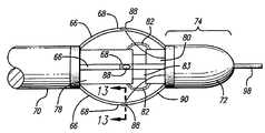
- FIG. 12is an enlarged side view of the working end of the embodiment of the directional catheter shown in FIG. 11 showing the bowable electrodes, temperature sensors, guide wire, and stop surface arrangement, in accordance with aspects of the present invention
- FIG. 13is a partial cross-sectional view of a bowable electrode of the catheter taken across lines 13 — 13 in FIG. 12 in accordance with aspects of the present invention
- FIG. 14is a schematic view of mounting deployable discrete electrode pairs so that they remain the same distance apart when they have been expanded;
- FIG. 15is a flux diagram showing the arrangement of discrete electrode pairs to achieve directionality and also shows the primary flux lines resulting from the arrangement;
- FIG. 16is a representative side view of a valve of a venous section being treated by the embodiment of the catheter of FIG. 11 in accordance with aspects of the present invention
- FIG. 17is a front cross-sectional view of the commissures of the venous section being treated by the embodiment of the catheter of FIG. 11 in accordance with aspects of the present invention.
- FIG. 18is a front cross-sectional view of the leaflets of the valve of the venous section being treated by the embodiment of the catheter of FIG. 11 in accordance with aspects of the present invention
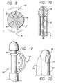
- FIG. 19is a side view of another embodiment of a catheter having one pair of bowable electrodes in accordance with aspects of the present invention.
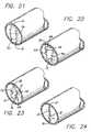
- FIG. 20is a side view of another embodiment of a catheter having a balloon formed on the catheter shaft opposite one pair of electrodes in accordance with aspects of the present invention
- FIG. 21is a representative view of a venous section having an incompetent valve which is being treated at one commissure by a catheter having an electrode pair (not shown) and an inflated balloon opposite the electrode pair to position the electrode pair in apposition with the commissure, in accordance with aspects of the present invention
- FIG. 22is a view similar to FIG. 21 showing the electrode pair of the catheter of FIG. 21 positioned in apposition with the opposite commissure by the inflated balloon, in accordance with aspects of the present invention
- FIG. 23is a cross-sectional view of treatment of a leaflet of the valve of FIGS. 21 and 22 in accordance with aspects of the present invention where the balloon has once again been inflated to position the electrode pair as desired;
- FIG. 24is a view of a competent valve resulting from the activity shown in FIGS. 21 through 23 ;
- FIG. 25is a view of an alternate embodiment of a directional catheter in which optical energy is directionally applied to the vein wall to cause shrinkage.
- the inventionis embodied in a system and method for the intravenous treatment of veins using a catheter to deliver an energy-application element, such as a pair of electrodes, to a venous treatment site.
- an energy-application elementsuch as a pair of electrodes
- RF energyfrom the electrode
- other forms of energysuch as microwaves, ultrasound, direct current, circulating heated fluid, optical energy, radiant light, and LASERs may be used, and that the thermal energy generated from a resistive coil or curie point element may be used as well.
- like reference numeralswill designate corresponding or similar elements in the various embodiments of the present invention to be discussed.
- working endwill refer to the direction toward the treatment site in the patient
- connecting endwill refer to the direction away from the treatment site in the patient.
- the following embodimentsare directed to the treatment of the venous system of the lower limbs. It is to be understood, however, that the invention is not limited thereto and can be employed intraluminally to treat veins in other areas of the body such as hemorrhoids, esophageal varices, and venous-drainage-impotence of the penis.
- FIG. 1A partial cross-sectional view of a dilated vein 10 from a lower limb having incompetent valves is shown in FIG. 1 .
- These veinsare often disposed within muscle tissue. Veins have bicuspid valves, and in a normal and competent valve 12 , as shown in the upper part of the vein, each cusp forms a sack or reservoir 14 for blood which, under pressure, forces the free edges of the cusps together to prevent retrograde flow of the blood and allow only antegrade flow to the heart.
- the arrow 16 leading out the top of the veinrepresents the antegrade flow of blood back to the heart.
- the venous valvesprevent retrograde flow as blood is pushed forward through the vein lumen and back to the heart.
- incompetent valve 18When an incompetent valve 18 , such as those shown in the lower part of the vein, encounters retrograde flow, the valve is unable to close, the cusps do not seal properly, and retrograde flow of blood may occur. Incompetent valves may result from the stretching of dilated veins. As the valves fail, increased pressure is imposed on the lower veins and the lower valves of the vein, which in turn exacerbates the failure of these lower valves. The valve cusps can experience separation at the commissure due to the thinning and stretching of the vein wall at the cusps. Valves can also become incompetent as a result of loose, floppy valve leaflets that can prolapse in response to retrograde blood flow or high proximal venous pressure.
- a method of minimally invasive treatment of venous insufficiency and valvular incompetencyincludes utilizing a catheter to deliver bipolar electrodes to a venous treatment site.
- a cross-sectional perspective view of a dilated vein taken along lines 2 — 2 of FIG. 1is illustrated in FIG. 2 .
- the electrodesdirectionally provide RF energy at the working end of the catheter to heat and shrink selected venous tissue between the electrodes.
- the directional application of RF energyin effect forms a heating zone along a portion of the catheter, and allows for localized or preferential heating of venous tissue so that shrinkage of the venous tissue can be limited to selected areas of the vein, such as the commissures of venous valves to restore venous valvular competency.
- the venous tissue at the commissurescan be heated, and the resulting shrinkage can bring the cusps of the venous valve closer together to restore competency. Further shrinkage of the cusps and leaflets can be achieved, if necessary, by moving or rotating the catheter and applying RF energy directionally to the leaflets to cause localized preferential heating and shrinking of the valve leaflets.
- the outcome of this directional application of RF energyis similar in effect to surgically placing reefing sutures into a floppy valve leaflet during venous valvuloplasty surgery.
- FIGS. 2 through 6An embodiment of the catheter 20 having a working end 22 having a pair of electrodes for 24 and 26 causing localized heating of the surrounding venous tissue and shrinkage of the vein is illustrated in FIGS. 2 through 6 .
- the working end 22includes electrodes 24 and 26 for providing RF energy to form a localized heating zone in the tissue at and between the electrodes.
- the electrodes 24 and 26can be conductive strips, plates, or wires embedded in the working end 22 of the catheter. RF energy conducted between the electrodes 24 and 26 through contacting venous tissue causes that tissue and surrounding adjacent venous tissue to be heated and shrink.
- the RF energyis directional between the electrodes of the catheter, and can be directionally applied to the surrounding venous tissue, including the commissures, cusp and leaflets of the venous valves, or to a specific radial arc of the vein wall.
- the method of the present invention for the minimally invasive treatment of venous insufficiencypreferably uses RF electrodes and a delivery catheter to restore the competency of a vein.
- the methodis contemplated to be used with any suitable appliance for directionally applying radiant energy or heat in the repair or reconfiguration of incompetent veins.
- the electrodes for generating the heating effect for shrinking the surrounding venous tissuecan be introduced either antegrade or retrograde. Particular discussion will be made of the treatment of varicose veins in the legs, though the method is well suited to treating veins in other areas of the body.
- the patientWhen treating the veins of the lower limbs, the patient is typically placed onto a procedure table with the feet dependent in order to fill the veins of the leg.
- the leg of the patientis prepped with antiseptic solution.
- a percutaneous introduceris inserted into the vein using a common Seldinger technique to access the saphenous or deep vein system.
- a venous cutdowncan be used to access the vein system to be treated.
- the procedure for the repair of incompetent veinscan be accomplished by a qualified physician with or without fluoroscopic or ultrasonic observation, or under direct visualization. Further, the physician could palpate the treatment area to determine the location of the catheter, and the treatment site, during the procedure when treating the superficial venous system. The physician may also palpate the vein into apposition with the electrodes to achieve good contact between the electrodes and the vein wall.
- the delivery catheter 20could be passed within the vein after insertion through the skin.
- a guide wire for the cathetercan be inserted into the vein.
- the wireis advanced antegrade to the level of the most proximal incompetent vein valve which is to be repaired.
- the delivery catheteris then inserted upon the wire and is fed up the leg through the vein to the level of the dilated venous section to be treated. Fluoroscopy, ultrasound, or an angioscopic imaging technique is then used to direct the specific placement of the catheter and confirm the position within the vein. Contrast material can be injected through or around the catheter to identify the incompetent venous sections to be repaired. A retrograde venogram can be performed in some cases to better localize the treatment site and effect.
- the cathetercan be placed adjacent the incompetent valve of the vein to be treated.
- the catheter 20travels to a venous valve, and is positioned so that the electrodes can treat specific portions of the vein.
- the catheter 20can be manipulated or torqued so that the working end 22 of the catheter is positioned to one side of the valve along the commissure.
- the cathetercan include cables, an inflating balloon, or bowable members which can selectively move the catheter to one side in order to properly position the working end of the catheter against selected venous tissue.
- an RF generatorelectrically connected to the electrodes, is activated to provide suitable RF energy, preferably at a selected frequency from a range of 250 kHz to 350 MHz.
- suitable frequencyis 510 kHz.
- One criterion used in selecting the frequency of the energy to be appliedis the control desired over the spread, including the depth, of the thermal effect in the venous tissue. Another criterion is compatibility with filter circuits for eliminating RF noise from thermocouple signals.
- the RF energyis converted within the adjacent venous tissue into heat, and this thermal effect causes the venous tissue to shrink.
- the shrinkageis due to structural transfiguration of the collagen fibers in the vein.
- the collagen fibrilsshorten and thicken in cross-section in response to the heat from the thermal effect. Although the collagen becomes more compacted during this process, it still retains some elasticity.
- RF energyis directionally applied to treat one commissure 28 , as shown in FIG. 2 .
- the catheteris then moved to treat the commissure 30 on the opposite side of the vein, as shown in FIG. 3 .
- Gross shrinkage of the vein diameter or shrinkage of the venous tissue at the commissures 28 and 30can restore competency to the venous valve, where the valve leaflets 32 are brought closer together. If the valve should remain incompetent, and continue to close improperly with prolapsing leaflets 32 , manipulating and rotating the working end 22 of the catheter 20 for the further application of RF energy to the leaflets 32 of the venous valve, as shown in FIG. 4 , can shrink the otherwise stretched and prolapsing leaflets 32 of the incompetent valve to restore valve competency if necessary. Where the leaflets 32 remain apart, energy applied directly to the leaflets of near the leaflets may cause them to move closer together. An approach is shown in FIG. 4 where energy is applied to the edges of the leaflets to cause them to move closer together. Applying energy to the edges of the leaflets is preferred over applying energy directly to the centers of the leaflets. However, energy can also be applied to the centers.
- FIGS. 2 through 5Preferentially shrinking the venous tissue in and around the venous valve is shown in the front diagrammatic, cross-sectional views of FIGS. 2 through 5 . Competency, as shown in FIG. 5 , of the valve is restored by this process.
- a deflection meanssuch as a bowable member or balloon or other means may be mounted on one side of the distal end of the catheter and deployed to selectively position the catheter at the site. Alternatively, other means may be used to selectively position the catheter distal end, such as a steering cable or cables.
- FIGS. 2 and 3a catheter 20 having electrodes 24 and 26 only on one side is shown. This is the preferred arrangement so that the possibility of heating the blood is reduced.
- Such a catheter, and a positioning device,is shown in FIGS. 19 and 20 , discussed later.
- the catheter 20 shown in FIG. 4on the other hand has electrodes 25 and 27 that extend over opposite sides of the catheter shaft at the working end 22 . This has the advantage of allowing the application of energy to both leaflet edges simultaneously.
- Vein dilationis reduced after RF energy applied from the electrodes heats the surrounding venous tissue to cause shrinkage. RF energy is no longer applied after there has been sufficient shrinkage of the vein to alleviate the dilation of the vein near the valves, so as to restore venous function or valvular competency.
- Sufficient shrinkagecan be detected by fluoroscopy, external ultrasound scanning, intravascular ultrasound scanning, direct visualization using an angioscope, or any other suitable method.
- the catheter 20can be configured to deliver an x-ray contrast medium to allow visualization by fluoroscopy for assessing the condition of the vein and the relationship of the catheter to the treatment area of the vein during the shrinkage process.
- external ultrasound techniquessuch as B-scanning using distinct ultrasound signals from different angles, or intravascular ultrasound can be used to acquire a more multidimensional view of the vein shrinkage at the treatment site.
- An angioscopecan also be used to directly visualize and determine the extent and degree of vein shrinkage.
- Valvular competencecan be determined by contrast injection or Doppler probe measurement.
- Substantial shrinkagemay occur very rapidly, depending upon the specific treatment conditions. Because the shrinkage can proceed at a rather rapid rate, the RF energy is preferably applied at low power levels.
- the properties of the treatment sitesuch as temperature, can be monitored to provide feedback control for the RF energy in order to minimize coagulation.
- Other techniquessuch as impedance monitoring, and ultrasonic pulse echoing, can be utilized in an automated system which shuts down the application of RF energy from the electrodes to the venous section when sufficient shrinkage of the vein is detected and to avoid overheating or coagulation in the vein. Monitoring these values in an automatic feedback control system for the RF energy can also be used to control the spread, including the depth, of the heating effect. In all instances, the application of RF energy is controlled so as to shrink the venous tissue sufficiently to restore the competency of the venous valve.
- the catheter 20After treating the first venous section shown, the catheter 20 is moved to the next venous valve suffering from insufficiency.
- the catheter 20can be repositioned to treat as many venous sections and valves as necessary.
- RF energyis applied to each venous section to be repaired, until all of the desired venous sections are repaired and the valves are rendered competent.
- Multiple incompetent valves and dilated venous sectionscan be treated and repaired in a single minimally invasive procedure.
- a second introducercan be inserted into the limb of a patient in order to access either the deep or the superficial vein system, whichever has yet to be treated. The catheter can then be used to treat incompetent venous sections in the other vein system.
- the catheterincludes a fluid delivery lumen, such as a guide wire lumen through which cooling fluid may be introduced
- the cooling fluidcan be delivered to the bloodstream during RF heating of the vein being treated.
- the delivered cooling fluidreduces any heating effect on the blood, and reduces the risk of heating the blood to the point of coagulation.
- the fluidmay also be delivered through ports formed along the side of the catheter near the working end and the electrodes (not shown).
- the catheter and electrodesare removed from the vasculature.
- the access point of the veinwould be sutured closed if a cutdown had been performed, or local pressure would be applied after percutaneous sheath removal until bleeding was controlled. A bandage would then be applied. A pressure dressing may be necessary. Elastic pressure gradient stockings may be worn subsequently.
- the cathetercan deliver the electrodes to the venous treatment site from a retrograde approach.
- the catheteris introduced into a percutaneous sheath that has been inserted through the skin and into the vein in a retrograde direction.
- the electrodes at the working end of the catheterare advanced until contact with the cusp of the venous valve is observed by fluoroscopy, ultrasound, or other detection method.
- the catheteris then pulled back slightly to allow treatment of the dilated valve sinus or leaflets in the vein.
- the catheteris capable of being deflected, torqued, or otherwise moved to allow for proper placement of the electrodes.
- Manipulating the working end of the catheterenables preferential heating along the vein being treated, where the electrodes are placed closer to one side of the vein wall, such as the commissure.
- the electrodesare activated to deliver RF energy to the venous tissue and shrink the vein. Placing the electrodes in close apposition to the commissures of the venous valve to cause local or preferential shrinkage near the commissures can remedy separation of the commissures from vein dilation and restore venous function and valvular competency.
- the cathetercan then be torqued to place the electrodes near the commissure at the opposite end of the valve. After the venous tissue at the commissures are shrunk, and the procedure can be repeated for the valve leaflets if necessary.
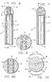
- FIG. 6A partial cross-sectional plan view of an embodiment of a catheter 34 is shown in FIG. 6 .
- the tip of the working end 36 of the cathetercan be formed from polymers or other non-conductive materials.
- Both electrodes 38 and 40are preferably made from stainless steel.
- the electrodesmay take the form of electrode plates as shown in FIG. 7 , which is a cross-sectional view taken along lines 7 — 7 of FIG. 6 .
- the electrodescan be flush with or protrude slightly from the surface of the non-conductive working end of the catheter. Further, the electrodes can be slightly recessed at the front tip of the working end so as to minimize the formation of an RF field in front of the catheter.
- the electrodescan be wires located along or embedded in the surface of the working end 36 as shown in FIG. 10 .
- the wiresgenerate heat when suitable energy is applied.
- the wiresmay be formed of a resistive material and heat up when electricity is conducted through them.
- FIG. 8An end view of the working end of the bipolar electrode catheter 34 is shown in FIG. 8 .
- the electrodesare connected to an RF generator so that they have opposite polarity. Therefore, current will flow between them through contacting venous tissue. This arrangement results in a directional application of energy localizing the energy along a portion of the catheter at the working end.
- the ports 28 at the working endcan provide cooling fluid or contrast injections to the vein during treatment.
- the working end 36 of the catheter 34is rounded to provide an atraumatic tip for the catheter as it is manipulated within the vein lumen.
- the outer diameter (O.D.) of the working endin this case, is slightly larger than the dimensions of the catheter shaft 44 .
- the working end 36 of the catheter 34can have a much enlarged dimension to form a bulbous shape which limits the amount of vein shrinkage around the working end.
- Different sized working ends and electrodescan be manufactured separately from the catheter shaft 44 for later assembly with the shaft 44 of the catheter so that a single catheter shaft 44 can be used with working ends having a variety of diameters.
- a working end having a specific size or shapecould then be used with the catheter depending on the size and type of vein being treated. For example, certain larger veins may have a diameter of seven to fifteen millimeters (mm), while other veins may only have a diameter of three to five mm.
- the catheter 34includes a stranded, twisted center conductor 46 surrounded by a layer of insulation 48 ( FIG. 7 ) which is preferably formed from TFE Teflon®.
- a silver coated copper braid 50surrounds the insulated center conductor, and provides flexible and torqueable characteristics to the catheter shaft 44 .
- a sheath 52covers the copper braid 50 , and is preferably made of an electrically resistive, biocompatible material with a low coefficient of friction such as Teflon®.
- the center conductor 46is connected to a power source such as an RF generator, to provide RF energy to the electrodes 38 and 40 .
- the power sourcecan be controlled by a microprocessor in response to external commands or to data from a sensor located at the venous treatment site such as the temperature sensor 54 shown in FIG.
- One electrode plate 38can be in electrical connection with the center conductor 20 of the RF generator thus giving that electrode a “+” polarity.
- the other electrode plate 40is connected to ground through the outer braid 50 thereby giving it a “ ⁇ ” polarity.
- the temperature sensor 54is located between the electrodes 38 and 40 . Other sensors may be used and may be mounted in other locations.
- the catheter shaft 44 and electrodes 38 and 40should be constructed from materials that would allow their visualization under fluoroscopy, X-ray, ultrasound or other imaging techniques.
- shrinkage of the veinis detected by fluoroscopy or external ultrasound techniques.
- a contrast mediumcan be injected into the vein to assess the condition of the vein and the relationship of the catheter to the treatment area of the vein by phlebography during the shrinkage process.
- the catheter 34can also be configured to deliver x-ray contrast material.
- external ultrasound techniquessuch as B-scanning using distinct ultrasound signals from different angles to acquire a more multi-dimensional view of the vein shrinkage at the treatment site, which improves the detection of uneven shrinkage in the vein lumen than would otherwise be obtainable from a simple two-dimensional approach, can be used to assess vein shrinkage.
- the multidimensional approachcan assist in orienting the working end of the catheter in directionally applying RF energy to selected portions of the vein and venous valve.
- An angioscopecan also be used to directly visualize the catheter, its position and orientation, and determine the degree of vein shrinkage.
- the sensing element 54comprises a temperature sensor such as a thermistor or a thermocouple.
- the temperature sensorcan be included on the catheter near the electrodes on the working end to monitor the temperature surrounding the electrodes and the venous section being treated.
- a temperature sensor placed between the electrodescan provide a measure of vein tissue temperature. Monitoring the temperature of the vein tissue can provide a good indication of when shrinkage of the vein tissue is ready to begin. The collagen fibrils of vein tissue shrink at approximately 70° centigrade (C) or higher.
- monitoring a thermocouple temperature sensor placed on the electrode facing the vein wallcan also provide an indication for when shrinkage occurs (i.e., 70° C.
- RF energy from the electrodesis halted or reduced when the monitored temperature reaches or exceeds the specific temperature at which venous tissue begins to shrink.
- the signals from the temperature sensorcan be input to a microprocessor which controls the magnitude of RF energy to the electrodes in accordance with the monitored temperature ( FIG. 11 ).
- another embodimentincludes ultrasonic piezoelectric elements 55 which emit pulsed ultrasound waves.
- the piezoelectric elements 55are operated in pulse-echo fashion to measure the distance to the vein wall from the catheter shaft. Again, the signals representative of the pulse-echo would be input to the microprocessor or to a monitor to allow for manual control, and the application of RF energy would be controlled accordingly.
- FIG. 9is an end view of an alternate embodiment of the catheter 34 having two pairs of discrete electrodes 58 at the working end.
- One electrode from each pairis connected to a center conductor attached to the positive terminal from a bipolar RF generator.
- the other electrode from each pairis connected to the metal braid of the catheter which is attached to the negative terminal of the bipolar RF generator.
- the positive electrode of one pairis located adjacent the positive electrode of the other pair, as are the negative electrodes.
- This arrangementresults in a directional application of RF energy from the catheter as RF current will flow primarily between electrodes of opposite polarity in the pairs of electrodes.
- each electrode in FIG. 9has two adjacent electrodes, one of like polarity and one of unlike polarity.
- a temperature sensor 54is preferably located between the electrodes of unlike polarity. Where there is a central lumen 42 that can accommodate fluid delivery or a guide wire, the RF power leads are wound around the lumen liner made of HDPE or other polymers. The temperature sensor leads (not shown) run the length of the catheter to a thermocouple 54 located between the electrodes.
- the electrodesare formed of metallic strips disposed on the outer surface of the distal tip or working end of the catheter.
- the electrodesmay be thicker and may be embedded in the distal tip. Additionally, more pairs of electrodes may be added depending on their size.
- FIG. 10presents yet another embodiment of the working end of a catheter where the electrodes comprise wires (only one is shown) that are exposed for conducting RF energy to venous tissue.
- the electrodescomprise wires (only one is shown) that are exposed for conducting RF energy to venous tissue.
- One wirewould be connected to the RF generator to have a positive polarity while the other wire would be connected to the opposite or negative polarity.
- the center conductor 62is wound around the guide wire lumen.
- FIGS. 11 and 12Another embodiment of the catheter including bowable electrodes disposed on the working end to cause localized heating of the surrounding venous tissue through the directional application of energy is shown in FIGS. 11 and 12 .
- the catheter 64includes four conductive elongate members 66 or arms (three can be seen) that can be bent or bowed outward.
- the elongate members 66are surrounded by insulation, except for an exposed area that serves as the electrode 68 (shown in FIG. 12 ). Electrodes 68 that can be controllably moved outwardly from the catheter by these arms 66 will be referred to as bowable electrodes 66 .
- the bowable electrodes 66are formed along the circumference of the catheter 64 , but are not fixed to the catheter. Bowing the electrodes outwardly also puts the electrodes in apposition with the venous tissue to be treated, and consistent contact of the electrode with the venous tissue can be maintained.
- the bowable electrodespreferably expand out to treat veins up to fifteen mm.
- the bowable electrodes 66are connected to a slidable tube 70 and a fixed tip 72 at the working end 74 , where moving the tube 70 controls the diameter of the electrode deployment for proper treatment of vein lumen having different diameters.
- the inner stop tube 78is connected to the slidable tube 70 and acts as a stop device as the slidable tube 70 and inner stop tube 78 are slid over the inner shaft 83 by making contact with the stop surface 80 that is fixed in position with the tip. The inner stop tube 78 thus interacts with the stop surface 80 to limit the amount of deployment of the bowable electrodes 66 .
- a fluid cover 82shown here in cutaway form as a bellows, prevents fluids from entering the space between the inner shaft 83 and the inner stop tube 78 and is discussed in greater detail below.
- a guide wire 98is seen protruding out the working end 74 .
- the bowable electrodesare connected to an RF generator 84 .
- a microprocessor 86Also connected to the RF generator is a microprocessor 86 .
- Each bowable electrode in this embodimenthas a thermocouple temperature sensor 88 mounted at the electrode surface 68 . Signals from the sensors 88 are coupled to the microprocessor 86 which compares them to a threshold temperature or temperatures to determine if RF energy to the electrodes should be interrupted or should be continued.
- the microprocessor 86controls the RF generator 84 accordingly.
- the catheter itselfis fit through a suitably sized sheath for the procedure.
- a suitably sized sheathfor the procedure.
- a seven French sheathwhich has about a 2.3 mm diameter, may be used.
- the sheathis composed of a biocompatible material with a low coefficient of friction.
- the working end 74 of the catheterincludes a tip 72 that is attached to one end of each electrode, and the other end of each electrode is connected to the sliding outer tube 70 formed along the exterior of the catheter shaft.
- the outer tube 70extends down the length of the catheter to allow the physician to directly and mechanically control the effective electrode diameter during the application of RF energy.
- the electrodes 66are urged radially outward and inward, respectively.
- the tip 72essentially remains stationary while the outer tube is moved. Moving the outer tube 70 back toward the connecting end of the catheter pulls back and flattens the electrodes against the catheter before insertion or withdrawal from the vein. Moving the outer tube 70 forward toward the working end 74 of the catheter causes the electrodes to deflect and radially bow outward to an increased diameter. The contact area 68 of the electrodes is bowed outwardly as the opposite ends of the longitudinal electrode are moved closer together. The outer sleeve may be moved a preset distance to cause the electrodes to bow outwardly to a known diameter.
- Bowing the electrodes outwardlyalso places the electrodes in apposition with the venous tissue to be treated.
- the slidable outer sleeveBy manipulating the slidable outer sleeve to adjust the effective diameter of the catheter defined by the radial bowing of the electrodes, contact between the electrodes and the venous tissue can be maintained during shrinkage.
- the control actuator 76is a switch, lever, threaded control knob, or any other suitable mechanism, preferably one that can provide fine control over the movement of the outer tube. By using the control actuator to move the tube, the effective diameter of the electrode can be controlled for treating vein lumina having different diameters, and for providing varying degrees of vein shrinkage.
- a movable tipis connected to the actuator 76 by a control wire running through the catheter, so that the movable tip can be manually controlled by the actuator located at the connecting end of the catheter to cause the electrodes 66 to deploy or to contract.
- the distal tip 72is shown to have a nosecone shape, but can have other shapes that allow tracking of the catheter over the guide wire and through bends in the venous vascular system.
- the nosecone-shaped tip 72can be fabricated from a polymer having a soft durometer, such as 70 Shore A.
- the tipcan be constructed from a spring covered with a thin layer of polyethylene shrink tubing.
- the bowable electrodes 66can be bowed radially outward to treat specific sections or areas in the vein.
- RF energyis applied to the bipolar electrodes, a discrete RF field is created around a portion of the catheter as defined by each active pair of the bowed electrodes.
- the RF fieldis directed toward specific venous tissue to be treated.
- the venous tissuebecomes heated and begins to shrink.
- the extent of venous shrinkageis monitored by fluoroscopy, or any other suitable method. After sufficient shrinking the venous tissue has occurred, the application of RF energy from the electrodes 66 is ceased.
- a cover 82is placed over the catheter shaft between the mounts for the bowable members and the stop devices 78 and 80 . As the outer tube 70 slides over the catheter shaft, the cover 82 prevents blood from seeping back through the interface between these two catheter components.
- the coveris preferably manufactured from a flexible polymer such as a low density polyethylene.
- the cover 82comprises accordion pleats taking the form of a bellows in one embodiment to allow the cover to expand and contract as the outer sleeve is moved to expand or retract the bowable electrodes 66 , but may also take other forms such as a polymer tube.
- the electrodesare retracted towards the catheter by the bowable members, and the pleated folds of the cover 82 flatten out. As the outer tube 70 is moved toward the tip, the pleated folds would move closer together.
- the electrodes 66may be fabricated from spring steel, stainless steel, or nitinol so that the electrodes 66 would be biased to return to a reduced diameter profile.
- the electrodesin one embodiment comprise flat strips to facilitate flexing of the catheter at the working end while being delivered through the bands of tenuous venous vasculature.
- the stripshave relatively large flat surfaces for contacting the vein wall can be used.
- Such rectangular wirescan have widths ranging from 0.005 to 0.05 inches, and preferably between 0.015 and 0.030 inches, to allow four or more electrodes around the catheter shaft.
- Rounded wiresmay also be used with a diameter preferably between about 0.005 to 0.015 inches (about 0.12 to 0.35 mm), but can be up to about 0.03 inches (about 0.7 mm).
- the entire length of the bowable longitudinal electrodeis conductive, and insulation 90 may be provided over the majority of the electrode surface in order to prevent any unintended heating effects. Only a modest portion of the conductive surface 68 is exposed to act as the electrode. The exposed surface can be placed closer to the tip 72 so that when the bowable electrodes are moved away from the catheter, the exposed conductive surface of the electrodes will be near the tip 72 which can be positioned adjacent the commissures and leaflets of the vein. The heating effect is greatest when the electrodes are close together since the electrical field density (power density) is greatest at this point.
- the ends of the electrodesare insulated from each other to prevent creating larger electrical field densities at the ends, especially as the effective diameter increases which would create even greater field disparities between the ends and the bowed midsection where the electrode gap is larger.
- the insulation 90can be polyimide, paralyene, or another type of insulating film. Insulation 90 provided along the inner radius of the bowable electrodes away from the venous tissue further prevents heating the blood flowing in the vein and reduces the likelihood of coagulation.
- the remaining exposed area 68 of the electrodeis preferably the area which contacts the venous tissue during apposition. The heating effect is then focused along that portion of the venous tissue and between the positive and negative electrodes.
- the exposed area which functionally acts as the electrodewould then occupy only one face of that wire.
- the insulation 90 surrounding the electrodecan further cover the peripheral edges of the exposed face of the electrode to further isolate the blood flow from unintended heating effects.
- a sensor 88such as a small thermocouple for measuring temperature is attached to the electrode 66 .
- the temperature sensor 88is soldered in place through a hole in the electrode so that the sensor is nearly or substantially flush with the exposed surface of the electrode.
- the sensorcan accurately sense the temperature of the vein wall in apposition with the exposed electrode surface.
- the leads 92 to the sensorare situated on the opposite side of the electrode which is insulated.
- the gap between electrodesmay increase which can weaken the RF field formed between the electrodes. Maintaining a constant gap or distance between the relevant electrodes of opposite polarity would allow a uniform RF field to be applied throughout the procedure as the vein diameter shrinks. Having a uniform RF field regardless of the diameter defined by the bowed out electrodes would also increase the predictability of the shrinkage.
- one embodimentwould have the bowable members containing the electrodes mounted on a rectangular or squarish mounting surface, as shown in FIG. 14 .
- the electrodes 94would lie roughly along the same plane, and would generally remain the same distance apart as the electrodes are moved outwardly by the parallel bowable members along the same plane. Preferably, a 1.0 to 1.5 mm gap is maintained between the electrodes forming the directional RF field.
- FIG. 15is an end schematic view of the working end of the bowable-electrode catheter 64 and the bowable electrodes 66 of FIGS. 11 , 12 and 13 .
- a preferred embodimentis to have the two pairs of bowable electrodes 66 spaced apart along the circumference of the catheter to form discrete pairs of electrodes.
- Each electrodewould have the opposite polarity from one of its adjacent electrodes and the same polarity as the other adjacent electrode. Electrodes of opposite polarity would form active electrode pairs to produce an RF field 96 between them. Thus, discrete RF fields 96 would be set up along the circumference of the catheter.
- the adjacent electrodes 66all had opposite polarities to one another, but were moved closer together to form discrete electrode pairs, two opposite pairs of active electrodes would be formed along the circumference of the catheter. While an RF field would be formed along the entire circumference of the catheter, the RF field would be strongest between the closely adjacent electrodes in each pair of opposite electrodes. As a result, heating and shrinkage would be concentrated between the electrodes of opposite polarity with a small inter-electrode gap.
- the working end of the catheterfurther includes a guide wire lumen 42 for accepting a guide wire 98 .
- the tip of the guide wire 98is preferably rounded.
- the guide wire lumen 42is preferably insulated so as to prevent or minimize any coupling effect the electrodes 66 may have on the guide wire.
- the guide wirecan be removed before the application of RF energy to the electrodes.
- the guide wire lumencan also allow for the delivery or perfusion of medicant and cooling solution to the treatment area during application of the RF energy.
- FIG. 16is a side view of the catheter of FIGS. 11 , 12 , and 13 being deployed from an antegrade approach to treat an incompetent valve.
- the leafletsare in contact with the bowable arms and RF energy may be applied just below them to the vein wall to reduce the diameter of the vein at the valve to restore valvular competency.
- FIGS. 17 and 18present another approach where the commissures are first shrunk ( FIG. 17 ) and then the catheter is used to impart RF energy to the leaflets, if needed ( FIG. 18 ).
- the bowable electrodes 66are expanded outward to treat the commissures on opposite sides of the vein simultaneously.
- the application of RF energyheats and shrinks the venous tissue at the commissures in order to restore valve competency.
- the application of RF energycan be halted, and the catheter manipulated to treat the leaflets if necessary, by retracting the bowable electrodes toward the body of the catheter as shown in FIG. 18 .
- the cathetermay also be pushed forward so as to come into closer proximity to the valve. Such treatment allows valve leaflet shrinkage to restore the competency of the venous valve.
- FIG. 19Another embodiment, shown in a side view in FIG. 19 , is similar to that shown in FIGS. 11 , 12 , and 13 except that only one pair of electrodes 100 is included on the catheter 102 .
- the electrodes 100are a pair of longitudinal electrodes located on one side of the catheter which can be bowed outwardly.
- the electrodes 100can have the same construction as the bowable electrodes described in connection with the embodiment illustrated in FIGS. 11 , 12 , and 13 for example.
- the operation of this embodimentis similar to that described previously, except that each of the commissures would be treated one at a time.
- this cathetercan be made in a manner to maintain a predetermined distance between the pairs of active electrodes despite outward bowing and diameter expansion.
- FIG. 20Another embodiment, shown in plan view in FIG. 20 comprises a catheter 103 that uses an asymmetrical balloon 104 to deflect the electrodes 106 at the working end of the catheter to one side.
- the balloon 104is located on the side of the catheter opposite to the electrode pair.
- the balloon 104When the balloon 104 is inflated, the opposite side of the working end accommodating the longitudinal electrodes 106 is moved into apposition with the venous tissue to be treated.
- the ballooncan be deflated, and the catheter removed from the vasculature.
- the other mechanisms for deflecting the working end of the cathetermay be used.
- a bendable actuation wire or strutmay be used on one side of the catheter in order to perform a function similar to that of the asymmetrical balloon.
- the catheteris similar in internal construction to the previously discussed embodiments.
- FIGS. 21 through 24present an example of an application of the directional energy application catheter 103 shown in FIG. 20 .
- an incompetent valve taken along lines 2 — 2 of FIG. 1is being treated at one commissure 30 by the catheter 103 of FIG. 20 having an electrode pair 106 (not shown) and an inflated balloon 104 opposite the electrode pair 106 to position the electrode pair in apposition with the commissure 30 .
- the electrode pair 106 of the catheter 103has been positioned by means of inflating the balloon 104 in apposition with the opposite commissure 28 .
- the electrode catheter 103has both electrodes 106 in apposition with one valve leaflet 32 to shrink the leaflet 32 .
- apposition with only the commissure 28 or 30may provide enough shrinkage of the vein so that contact with the leaflets 32 is not necessary.
- the directional catheter shown in FIGS. 19 and 20may also be used to reduce the size of or occlude an opening or ostium into a branch vein. Where such vein provides too great a flow into another vein, the ostium of the branch vein can be reduced in size to decrease the flow or occluded to terminate flow. In some cases, it is impractical to treat the branch vein itself; therefore, occluding its ostium may improve conditions. In such a case, a catheter such as that shown in FIGS. 19 and 20 may be used to heat the ostium or tissue adjacent the ostium to reduce its size. The electrodes would be positioned against the ostium wall by a positioning device, such as the balloon shown in FIG. 20 or the strut shown in FIG. 19 , and energy applied to reduce the ostium size.
- a positioning devicesuch as the balloon shown in FIG. 20 or the strut shown in FIG. 19 , and energy applied to reduce the ostium size.
- a catheter 130 having an optical fiber diffusing tip 132is used to directionally apply energy to a selected vascular segment.
- an optical fiber 134is disposed within the catheter 130 and is connected at its distal end to a light diffusing device 136 , such as a sapphire crystal, to allow diffusion of optical energy, such as that produced by a LASER connected to the proximal end of the catheter.
- the diffusing tipmay have a reflector 138 to direct the optical energy toward the wall of the vein and away from the catheter lumen in which the optical fiber is located.
- Other light sources, such as a flash lampmay be used.
- a tip deflecting wire or strut 140is shown in this embodiment to be deployed for placing the optical energy radiating tip 132 in apposition with the vein wall; however, other devices may be used for accurate placement of the energy source, such as a balloon shown in FIG. 20 .
- the outer sleeve 142 of the catheteris slidable. Sliding it toward the distal tip results in the strut 140 expanding and sliding the sleeve in the proximal direction results in the strut 140 contracting.
- the surgical procedure of the present inventionis accomplished without the need for prolonged hospitalization or post-operative recovery.
- the restoration of venous functionis possible without the need for continued lifestyle changes, such as frequent leg elevation, the wearing of elastic support stockings, or prolonged treatment of recurrent venous stasis ulcers.
- the need for surgery of the arm and leg for transplantation of arm veins into the legwould not be necessary.
- venous diseaseEarly treatment of venous disease could prevent more serious complications such as ulceration, and valve damage caused by thrombophlebitis or thromboembolism.
- the cost of treatment and complications due to venous diseasewould be significantly reduced. There would be no need for extensive hospitalization for this procedure, and the need for subsequent treatment and hospitalization would also be reduced from what is currently needed.
- the minimally invasive nature of the disclosed methodswould allow the medical practitioner to repair or treat several vein sections in a single procedure in a relatively short period of time.
- the type and dimensions of the catheter and electrodesmay be selected according to the size of the vein to be treated.
- the present inventionhas been described as treating venous insufficiency of the lower limb such as varicose veins in the leg, the present invention can be used to intraluminally treat venous insufficiency in other areas of the body.
- hemorrhoidsmay be characterized as outpocketed varicose veins in the anal region.
- Traditional treatmentsinclude invasive surgery, elastic ring ligation, and the application of topical ointments.
- Shrinking the dilated veins using RF energycan be accomplished in accordance with the present invention.
- the catheter and electrode combinationis introduced into the venous system, into the external iliac vein, the internal iliac vein, then either the hemorrhoidal or the pudendal vein.
- the catheterthen delivers the electrode to the site of the dilated hemorrhoidal vein by this transvenous approach.
- Fluoroscopic techniques or any other suitable techniquesuch as pulse-echo ultrasound, as previously discussed, can be used to properly position the electrode at the venous treatment site.
- the treatment siteis preferably selected to be at least two centimeters above the dentate line to minimize pain.
- the electrodeapplies RF energy at a suitable frequency to minimized coagulation for a sufficient amount of time to shrink, stiffen, and fixate the vein, yet maintain venous function or valvular competency.
- This intraluminal approachavoids the risks and morbidity associated with more invasive surgical techniques such as hemorrhoidectomy, while significantly reducing reflux of blood in the area without necrosing or removing the venous tissue.
- venous insufficiencyAnother area of venous insufficiency relates to erectile impotency of the penis.
- a significant number of all physically-induced cases of impotenceresult from excessive drainage of blood from the penile venous system.
- Venous-drainage-impotencecan be treated using the present invention.
- Catheters having a sufficiently small diametercan be used to deliver the electrodes through the dorsal vein of the penile venous system to shrink this venous outflow path. Fluoroscopic or ultrasound techniques can be used to properly position the electrode within the incompetent vein.
- RF energy or other radiant energyis applied from the electrodes at a suitable frequency to shrink the surrounding venous tissue in order to reduce the excessive amount of drainage from the penis while maintaining venous function or valvular competency.
- the amount of shrinkage of the veincan be limited by the diameter of the catheter itself, or the catheter or electrodes themselves can be expanded to the appropriate size. Ligation of these veins should be avoided so as to allow for the proper drainage of blood from an engorged penis which is necessary for proper penile function.
- esophageal varicescan form in the venous system along the submucosa of the lower esophagus, and bleeding can occur from the swollen veins.
- Properly sized catheterscan be used in accordance with the present invention to deliver the electrodes to the site of venous insufficiency along the esophageal varices. Endovascular access for the catheter is preferably provided through the superior mesenteric vein or portal vein to shrink the portal vein branches leading to the lower esophagus. Proper positioning of the electrode within the vein can be confirmed using fluoroscopic or ultrasound techniques.
- the electrodesapply RF energy or other radiant energy at a suitable frequency to shrink the vein and reduce the swelling and transmission of high portal venous pressure to the veins surrounding the esophagus.
Landscapes
- Health & Medical Sciences (AREA)
- Life Sciences & Earth Sciences (AREA)
- Surgery (AREA)
- Engineering & Computer Science (AREA)
- Plasma & Fusion (AREA)
- Medical Informatics (AREA)
- Otolaryngology (AREA)
- Physics & Mathematics (AREA)
- Cardiology (AREA)
- Biomedical Technology (AREA)
- Heart & Thoracic Surgery (AREA)
- Nuclear Medicine, Radiotherapy & Molecular Imaging (AREA)
- Molecular Biology (AREA)
- Animal Behavior & Ethology (AREA)
- General Health & Medical Sciences (AREA)
- Public Health (AREA)
- Veterinary Medicine (AREA)
- Surgical Instruments (AREA)
Abstract
Description
Claims (35)
Priority Applications (10)
| Application Number | Priority Date | Filing Date | Title |
|---|---|---|---|
| JP53198597AJP4060887B2 (en) | 1996-03-05 | 1997-03-04 | Vascular catheter utilization system for heating tissue |
| CA2248260ACA2248260C (en) | 1996-03-05 | 1997-03-04 | Vascular catheter-based system for heating tissue |
| PCT/US1997/003637WO1997032532A1 (en) | 1996-03-05 | 1997-03-04 | Vascular catheter-based system for heating tissue |
| US08/811,820US6033398A (en) | 1996-03-05 | 1997-03-04 | Method and apparatus for treating venous insufficiency using directionally applied energy |
| AU20734/97AAU733465B2 (en) | 1996-03-05 | 1997-03-04 | Vascular catheter-based system for heating tissue |
| EP97908960AEP0921765B1 (en) | 1996-03-05 | 1997-03-04 | Vascular catheter-based system for heating tissue |
| US08/895,850US6152899A (en) | 1996-03-05 | 1997-07-17 | Expandable catheter having improved electrode design, and method for applying energy |
| US09/483,969US6981972B1 (en) | 1996-03-05 | 2000-01-18 | Apparatus for treating venous insufficiency using directionally applied energy |
| US11/280,778US7976536B2 (en) | 1996-03-05 | 2005-11-16 | Method and apparatus for treating venous insufficiency |
| US13/095,335US8291915B2 (en) | 1997-03-04 | 2011-04-27 | Method and apparatus for treating venous insufficiency using directionally applied energy |
Applications Claiming Priority (5)
| Application Number | Priority Date | Filing Date | Title |
|---|---|---|---|
| US08/610,911US6036687A (en) | 1996-03-05 | 1996-03-05 | Method and apparatus for treating venous insufficiency |
| US08/717,994US6033397A (en) | 1996-03-05 | 1996-09-26 | Method and apparatus for treating esophageal varices |
| US08/720,209US6139527A (en) | 1996-03-05 | 1996-09-26 | Method and apparatus for treating hemorrhoids |
| US08/811,820US6033398A (en) | 1996-03-05 | 1997-03-04 | Method and apparatus for treating venous insufficiency using directionally applied energy |
| US09/483,969US6981972B1 (en) | 1996-03-05 | 2000-01-18 | Apparatus for treating venous insufficiency using directionally applied energy |
Related Parent Applications (1)
| Application Number | Title | Priority Date | Filing Date |
|---|---|---|---|
| US08/811,820DivisionUS6033398A (en) | 1996-03-05 | 1997-03-04 | Method and apparatus for treating venous insufficiency using directionally applied energy |
Related Child Applications (1)
| Application Number | Title | Priority Date | Filing Date |
|---|---|---|---|
| US11/280,778DivisionUS7976536B2 (en) | 1996-03-05 | 2005-11-16 | Method and apparatus for treating venous insufficiency |
Publications (1)
| Publication Number | Publication Date |
|---|---|
| US6981972B1true US6981972B1 (en) | 2006-01-03 |
Family
ID=46203076
Family Applications (3)
| Application Number | Title | Priority Date | Filing Date |
|---|---|---|---|
| US08/811,820Expired - LifetimeUS6033398A (en) | 1996-03-05 | 1997-03-04 | Method and apparatus for treating venous insufficiency using directionally applied energy |
| US09/483,969Expired - Fee RelatedUS6981972B1 (en) | 1996-03-05 | 2000-01-18 | Apparatus for treating venous insufficiency using directionally applied energy |
| US11/280,778Expired - Fee RelatedUS7976536B2 (en) | 1996-03-05 | 2005-11-16 | Method and apparatus for treating venous insufficiency |
Family Applications Before (1)
| Application Number | Title | Priority Date | Filing Date |
|---|---|---|---|
| US08/811,820Expired - LifetimeUS6033398A (en) | 1996-03-05 | 1997-03-04 | Method and apparatus for treating venous insufficiency using directionally applied energy |
Family Applications After (1)
| Application Number | Title | Priority Date | Filing Date |
|---|---|---|---|
| US11/280,778Expired - Fee RelatedUS7976536B2 (en) | 1996-03-05 | 2005-11-16 | Method and apparatus for treating venous insufficiency |
Country Status (6)
| Country | Link |
|---|---|
| US (3) | US6033398A (en) |
| EP (1) | EP0921765B1 (en) |
| JP (1) | JP4060887B2 (en) |
| AU (1) | AU733465B2 (en) |
| CA (1) | CA2248260C (en) |
| WO (1) | WO1997032532A1 (en) |
Cited By (28)
| Publication number | Priority date | Publication date | Assignee | Title |
|---|---|---|---|---|
| US20030191512A1 (en)* | 1996-03-05 | 2003-10-09 | Laufer Michael D. | Method and apparatus for treating venous insufficiency |
| US20060084861A1 (en)* | 2004-10-18 | 2006-04-20 | Topspin Medical (Isreal) Ltd. | Magnet and coil configurations for MRI probes |
| US20060084866A1 (en)* | 2004-10-18 | 2006-04-20 | Gadi Lewkonya | Expanding imaging probe |
| US20080125771A1 (en)* | 2006-11-27 | 2008-05-29 | Michael Lau | Methods and apparatuses for contouring tissue by selective application of energy |
| US20080234569A1 (en)* | 2004-01-20 | 2008-09-25 | Topspin Medical (Israel) Ltd. | Mri Probe for Prostate Imaging |
| US20080292255A1 (en)* | 2007-04-27 | 2008-11-27 | Vnus Medical Technologies, Inc. | Systems and methods for treating hollow anatomical structures |
| US20090137998A1 (en)* | 1997-09-11 | 2009-05-28 | Zikorus Arthur W | Expandable vein ligator catheter having multiple electrode leads, and method |
| US20090306637A1 (en)* | 2008-06-04 | 2009-12-10 | Vnus Medical Technologies, Inc. | Energy devices and methods for treating hollow anatomical structures |
| US20100152723A1 (en)* | 2005-02-23 | 2010-06-17 | Tyco Healthcare Group, Lp | Methods and apparatus for coagulating and/or constricting hollow anatomical structures |
| US20100268217A1 (en)* | 2006-05-24 | 2010-10-21 | Emcision Limited | Vessel sealing device and methods |
| US20110060388A1 (en)* | 2009-09-08 | 2011-03-10 | Ceramoptec Industries Inc. | Device and method for vessel treatment |
| US20110144642A1 (en)* | 2004-08-05 | 2011-06-16 | Tyco Healthcare Group, Lp | Method and apparatus for coagulating and/or constricting hollow anatomical structures |
| US20110166519A1 (en)* | 2010-01-04 | 2011-07-07 | Tyco Healthcare Group, L.P. | Apparatus and methods for treating hollow anatomical structures |
| US7976536B2 (en) | 1996-03-05 | 2011-07-12 | Tyco Healthcare Group Lp | Method and apparatus for treating venous insufficiency |
| US20110202047A1 (en)* | 1997-03-04 | 2011-08-18 | Farley Brian E | Apparatus for Treating Venous Insufficiency Using Directionally Applied Energy |
| US20150119878A1 (en)* | 2013-10-24 | 2015-04-30 | St. Jude Medical, Cardiology Division, Inc. | Electrode assembly having asymmetric electrode placement |
| US10603040B1 (en) | 2015-02-09 | 2020-03-31 | Tva Medical, Inc. | Methods for treating hypertension and reducing blood pressure with formation of fistula |
| US10646666B2 (en) | 2014-08-27 | 2020-05-12 | Tva Medical, Inc. | Cryolipolysis devices and methods therefor |
| US10695534B2 (en) | 2014-03-14 | 2020-06-30 | Tva Medical, Inc. | Fistula formation devices and methods therefor |
| US10821217B2 (en) | 2013-03-14 | 2020-11-03 | Tva Medical, Inc. | Fistula formation devices and methods therefor |
| US10869717B2 (en) | 2012-10-11 | 2020-12-22 | Tva Medical, Inc. | Devices and methods for fistula formation |
| US10874422B2 (en) | 2016-01-15 | 2020-12-29 | Tva Medical, Inc. | Systems and methods for increasing blood flow |
| US11026743B2 (en) | 2016-01-15 | 2021-06-08 | Tva Medical, Inc. | Devices and methods for forming a fistula |
| US11051880B2 (en) | 2010-11-16 | 2021-07-06 | Tva Medical, Inc. | Devices and methods for forming a fistula |
| US11285028B2 (en) | 2016-09-25 | 2022-03-29 | Tva Medical, Inc. | Vascular stent devices and methods |
| US11590322B2 (en) | 2016-01-15 | 2023-02-28 | Tva Medical, Inc. | Devices and methods for advancing a wire |
| US11877784B2 (en) | 2014-03-26 | 2024-01-23 | Venclose, Inc. | Venous disease treatment |
| US12295645B2 (en) | 2016-01-15 | 2025-05-13 | Tva Medical, Inc. | Systems and methods for adhering vessels |
Families Citing this family (349)
| Publication number | Priority date | Publication date | Assignee | Title |
|---|---|---|---|---|
| US6405732B1 (en) | 1994-06-24 | 2002-06-18 | Curon Medical, Inc. | Method to treat gastric reflux via the detection and ablation of gastro-esophageal nerves and receptors |
| US6056744A (en) | 1994-06-24 | 2000-05-02 | Conway Stuart Medical, Inc. | Sphincter treatment apparatus |
| AU733341B2 (en) | 1996-02-02 | 2001-05-10 | Transvascular, Inc. | A device, system and method for interstitial transvascular intervention |
| US6077257A (en)* | 1996-05-06 | 2000-06-20 | Vidacare, Inc. | Ablation of rectal and other internal body structures |
| US5891134A (en)* | 1996-09-24 | 1999-04-06 | Goble; Colin | System and method for applying thermal energy to tissue |
| US6464697B1 (en) | 1998-02-19 | 2002-10-15 | Curon Medical, Inc. | Stomach and adjoining tissue regions in the esophagus |
| US5827268A (en)* | 1996-10-30 | 1998-10-27 | Hearten Medical, Inc. | Device for the treatment of patent ductus arteriosus and method of using the device |
| US6081749A (en)* | 1997-08-13 | 2000-06-27 | Surx, Inc. | Noninvasive devices, methods, and systems for shrinking of tissues |
| US7317949B2 (en) | 1996-11-08 | 2008-01-08 | Ams Research Corporation | Energy induced bulking and buttressing of tissues for incontinence |
| US6035238A (en)* | 1997-08-13 | 2000-03-07 | Surx, Inc. | Noninvasive devices, methods, and systems for shrinking of tissues |
| US6292700B1 (en) | 1999-09-10 | 2001-09-18 | Surx, Inc. | Endopelvic fascia treatment for incontinence |
| US6091995A (en) | 1996-11-08 | 2000-07-18 | Surx, Inc. | Devices, methods, and systems for shrinking tissues |
| US7027869B2 (en) | 1998-01-07 | 2006-04-11 | Asthmatx, Inc. | Method for treating an asthma attack |
| US7992572B2 (en) | 1998-06-10 | 2011-08-09 | Asthmatx, Inc. | Methods of evaluating individuals having reversible obstructive pulmonary disease |
| US6488673B1 (en)* | 1997-04-07 | 2002-12-03 | Broncus Technologies, Inc. | Method of increasing gas exchange of a lung |
| US7425212B1 (en)* | 1998-06-10 | 2008-09-16 | Asthmatx, Inc. | Devices for modification of airways by transfer of energy |
| US6634363B1 (en)* | 1997-04-07 | 2003-10-21 | Broncus Technologies, Inc. | Methods of treating lungs having reversible obstructive pulmonary disease |
| US9023031B2 (en) | 1997-08-13 | 2015-05-05 | Verathon Inc. | Noninvasive devices, methods, and systems for modifying tissues |
| US6179832B1 (en) | 1997-09-11 | 2001-01-30 | Vnus Medical Technologies, Inc. | Expandable catheter having two sets of electrodes |
| US6258084B1 (en) | 1997-09-11 | 2001-07-10 | Vnus Medical Technologies, Inc. | Method for applying energy to biological tissue including the use of tumescent tissue compression |
| US6401719B1 (en) | 1997-09-11 | 2002-06-11 | Vnus Medical Technologies, Inc. | Method of ligating hollow anatomical structures |
| US6014589A (en)* | 1997-11-12 | 2000-01-11 | Vnus Medical Technologies, Inc. | Catheter having expandable electrodes and adjustable stent |
| US7921855B2 (en) | 1998-01-07 | 2011-04-12 | Asthmatx, Inc. | Method for treating an asthma attack |
| AU2317899A (en) | 1998-01-14 | 1999-08-02 | Conway-Stuart Medical, Inc. | Gerd treatment apparatus and method |
| CA2317410A1 (en) | 1998-01-14 | 1999-07-22 | Surx, Inc. | Ribbed electrodes and methods for their use |
| WO1999042044A1 (en) | 1998-02-19 | 1999-08-26 | Conway-Stuart Medical, Inc. | Electrosurgical sphincter treatment apparatus |
| US7165551B2 (en) | 1998-02-19 | 2007-01-23 | Curon Medical, Inc. | Apparatus to detect and treat aberrant myoelectric activity |
| US8906010B2 (en) | 1998-02-19 | 2014-12-09 | Mederi Therapeutics, Inc. | Graphical user interface for association with an electrode structure deployed in contact with a tissue region |
| US6358245B1 (en) | 1998-02-19 | 2002-03-19 | Curon Medical, Inc. | Graphical user interface for association with an electrode structure deployed in contact with a tissue region |
| US6645201B1 (en)* | 1998-02-19 | 2003-11-11 | Curon Medical, Inc. | Systems and methods for treating dysfunctions in the intestines and rectum |
| US20030135206A1 (en) | 1998-02-27 | 2003-07-17 | Curon Medical, Inc. | Method for treating a sphincter |
| US6561998B1 (en) | 1998-04-07 | 2003-05-13 | Transvascular, Inc. | Transluminal devices, systems and methods for enlarging interstitial penetration tracts |
| WO1999053854A2 (en)* | 1998-04-22 | 1999-10-28 | Cardiosynopsis, Inc. | Method and apparatus for treating an aneurysm |
| US6319241B1 (en) | 1998-04-30 | 2001-11-20 | Medtronic, Inc. | Techniques for positioning therapy delivery elements within a spinal cord or a brain |
| AU3672299A (en) | 1998-04-30 | 1999-11-16 | Stuart D Edwards | Electrosurgical sphincter treatment apparatus |
| US6161047A (en) | 1998-04-30 | 2000-12-12 | Medtronic Inc. | Apparatus and method for expanding a stimulation lead body in situ |
| US6974450B2 (en)* | 1999-12-30 | 2005-12-13 | Pearl Technology Holdings, Llc | Face-lifting device |
| US7494488B2 (en)* | 1998-05-28 | 2009-02-24 | Pearl Technology Holdings, Llc | Facial tissue strengthening and tightening device and methods |
| US6391023B1 (en)* | 1998-05-28 | 2002-05-21 | Pearl Technology Holdings, Llc | Thermal radiation facelift device |
| US6440121B1 (en)* | 1998-05-28 | 2002-08-27 | Pearl Technology Holdings, Llc. | Surgical device for performing face-lifting surgery using radiofrequency energy |
| US6802841B2 (en) | 1998-06-04 | 2004-10-12 | Curon Medical, Inc. | Systems and methods for applying a selected treatment agent into contact with tissue to treat sphincter dysfunction |
| US7198635B2 (en) | 2000-10-17 | 2007-04-03 | Asthmatx, Inc. | Modification of airways by application of energy |
| US8181656B2 (en) | 1998-06-10 | 2012-05-22 | Asthmatx, Inc. | Methods for treating airways |
| US6322559B1 (en)* | 1998-07-06 | 2001-11-27 | Vnus Medical Technologies, Inc. | Electrode catheter having coil structure |
| US6024742A (en)* | 1998-08-22 | 2000-02-15 | Tu; Lily Chen | Ablation apparatus for treating hemorrhoids |
| IL125990A (en)* | 1998-08-30 | 2004-12-15 | Moshe Ein-Gal | Electrocoagulation apparatus |
| US6254601B1 (en)* | 1998-12-08 | 2001-07-03 | Hysterx, Inc. | Methods for occlusion of the uterine arteries |
| ATE314015T1 (en)* | 1999-03-02 | 2006-01-15 | Atrionix Inc | POSITIONING SYSTEM FOR A PULMONARY OSTIUM ABLATION DEVICE |
| GB2333964B (en)* | 1999-03-04 | 1999-12-29 | Falah Hasan Ali | Intravenous coagulation catheter for treatment of varicose veins |
| US6425853B1 (en)* | 1999-06-23 | 2002-07-30 | Stuart D. Edwards | Treating body tissue by applying energy and substances with a retractable catheter and contained cooling element |
| EP1281366B1 (en)* | 1999-06-23 | 2006-10-11 | Novasys Medical, Inc. | Treatment of sphincters with electrosurgery and active substances |
| AU5884400A (en)* | 1999-06-25 | 2001-01-31 | Vahid Saadat | Apparatus and methods for treating tissue |
| WO2001017452A1 (en) | 1999-09-08 | 2001-03-15 | Curon Medical, Inc. | System for controlling a family of treatment devices |
| AU7352500A (en) | 1999-09-08 | 2001-04-10 | Curon Medical, Inc. | Systems and methods for monitoring and controlling use of medical devices |
| CA2388376A1 (en) | 1999-09-08 | 2001-03-15 | Curon Medical, Inc. | Systems and methods for monitoring and controlling use of medical devices |
| US20060095032A1 (en) | 1999-11-16 | 2006-05-04 | Jerome Jackson | Methods and systems for determining physiologic characteristics for treatment of the esophagus |
| US20040215235A1 (en) | 1999-11-16 | 2004-10-28 | Barrx, Inc. | Methods and systems for determining physiologic characteristics for treatment of the esophagus |
| EP1119178B1 (en)* | 1999-12-28 | 2010-04-14 | Sony Corporation | Image commercial transactions system and method |
| US6699237B2 (en)* | 1999-12-30 | 2004-03-02 | Pearl Technology Holdings, Llc | Tissue-lifting device |
| US6953461B2 (en) | 2002-05-16 | 2005-10-11 | Tissuelink Medical, Inc. | Fluid-assisted medical devices, systems and methods |
| ES2306706T3 (en) | 2000-03-06 | 2008-11-16 | Salient Surgical Technologies, Inc. | FLUID SUPPLY SYSTEM AND CONTROLLER FOR ELECTROCHURGICAL DEVICES. |
| US6558385B1 (en) | 2000-09-22 | 2003-05-06 | Tissuelink Medical, Inc. | Fluid-assisted medical device |
| US8048070B2 (en)* | 2000-03-06 | 2011-11-01 | Salient Surgical Technologies, Inc. | Fluid-assisted medical devices, systems and methods |
| US6689131B2 (en) | 2001-03-08 | 2004-02-10 | Tissuelink Medical, Inc. | Electrosurgical device having a tissue reduction sensor |
| US7811282B2 (en) | 2000-03-06 | 2010-10-12 | Salient Surgical Technologies, Inc. | Fluid-assisted electrosurgical devices, electrosurgical unit with pump and methods of use thereof |
| US8251070B2 (en) | 2000-03-27 | 2012-08-28 | Asthmatx, Inc. | Methods for treating airways |
| US7090645B2 (en) | 2000-04-04 | 2006-08-15 | Nv Thermocore Medical Systems Sa | Biased vascular temperature measuring device |
| JP4433560B2 (en)* | 2000-04-11 | 2010-03-17 | ソニー株式会社 | Terminal device and information processing method |
| US20030120306A1 (en)* | 2000-04-21 | 2003-06-26 | Vascular Control System | Method and apparatus for the detection and occlusion of blood vessels |
| US6550482B1 (en) | 2000-04-21 | 2003-04-22 | Vascular Control Systems, Inc. | Methods for non-permanent occlusion of a uterine artery |
| US7223279B2 (en) | 2000-04-21 | 2007-05-29 | Vascular Control Systems, Inc. | Methods for minimally-invasive, non-permanent occlusion of a uterine artery |
| US6773428B2 (en)* | 2000-05-12 | 2004-08-10 | Stephen M. Zappala | Implantable delivery system and method for the pharmacologic management of erectile dysfunction |
| US8845632B2 (en) | 2000-05-18 | 2014-09-30 | Mederi Therapeutics, Inc. | Graphical user interface for monitoring and controlling use of medical devices |
| US6508784B1 (en)* | 2000-05-19 | 2003-01-21 | Yan-Ho Shu | Balloon catheter having adjustable centering capabilities and methods thereof |
| DE20009426U1 (en)* | 2000-05-26 | 2001-10-31 | Desinger, Kai, Dr., 12157 Berlin | Surgical instrument |
| US20030204188A1 (en)* | 2001-11-07 | 2003-10-30 | Artemis Medical, Inc. | Tissue separating and localizing catheter assembly |
| US7534242B2 (en)* | 2003-02-25 | 2009-05-19 | Artemis Medical, Inc. | Tissue separating catheter assembly and method |
| WO2001097897A1 (en)* | 2000-06-20 | 2001-12-27 | Starion Instruments, Inc. | Devices and methods for repair of valves in the human body |
| US6527800B1 (en) | 2000-06-26 | 2003-03-04 | Rex Medical, L.P. | Vascular device and method for valve leaflet apposition |
| US6676698B2 (en)* | 2000-06-26 | 2004-01-13 | Rex Medicol, L.P. | Vascular device with valve for approximating vessel wall |
| US6695878B2 (en) | 2000-06-26 | 2004-02-24 | Rex Medical, L.P. | Vascular device for valve leaflet apposition |
| US20030120256A1 (en)* | 2001-07-03 | 2003-06-26 | Syntheon, Llc | Methods and apparatus for sclerosing the wall of a varicose vein |
| US20050107738A1 (en)* | 2000-07-21 | 2005-05-19 | Slater Charles R. | Occludable intravascular catheter for drug delivery and method of using the same |
| US20050113798A1 (en)* | 2000-07-21 | 2005-05-26 | Slater Charles R. | Methods and apparatus for treating the interior of a blood vessel |
| US7077836B2 (en)* | 2000-07-21 | 2006-07-18 | Vein Rx, Inc. | Methods and apparatus for sclerosing the wall of a varicose vein |
| US7306591B2 (en) | 2000-10-02 | 2007-12-11 | Novasys Medical, Inc. | Apparatus and methods for treating female urinary incontinence |
| US7104987B2 (en) | 2000-10-17 | 2006-09-12 | Asthmatx, Inc. | Control system and process for application of energy to airway walls and other mediums |
| WO2002064012A2 (en)* | 2000-11-07 | 2002-08-22 | Artemis Medical, Inc. | Target tissue localization assembly and method |
| US6575623B2 (en)* | 2000-11-10 | 2003-06-10 | Cardiostream, Inc. | Guide wire having extendable contact sensors for measuring temperature of vessel walls |
| AU6314301A (en)* | 2000-11-16 | 2002-05-27 | Robert A Ganz | System and method of treating abnormal tissue in the human esophagus |
| US6635065B2 (en)* | 2000-11-16 | 2003-10-21 | Vascular Control Systems, Inc. | Doppler directed suture ligation device and method |
| US6638286B1 (en) | 2000-11-16 | 2003-10-28 | Vascular Control Systems, Inc. | Doppler directed suture ligation device and method |
| US8038708B2 (en) | 2001-02-05 | 2011-10-18 | Cook Medical Technologies Llc | Implantable device with remodelable material and covering material |
| JP4227415B2 (en) | 2001-03-28 | 2009-02-18 | ヴァスキュラー・コントロール・システムズ・インコーポレーテッド | Method and apparatus for detecting and ligating uterine arteries |
| US20030120286A1 (en)* | 2001-03-28 | 2003-06-26 | Vascular Control System | Luminal clip applicator with sensor |
| US7354444B2 (en)* | 2001-03-28 | 2008-04-08 | Vascular Control Systems, Inc. | Occlusion device with deployable paddles for detection and occlusion of blood vessels |
| US6928320B2 (en) | 2001-05-17 | 2005-08-09 | Medtronic, Inc. | Apparatus for blocking activation of tissue or conduction of action potentials while other tissue is being therapeutically activated |
| US20040015159A1 (en)* | 2001-07-03 | 2004-01-22 | Syntheon, Llc | Methods and apparatus for treating the wall of a blood vessel with electromagnetic energy |
| US20060009740A1 (en)* | 2001-08-28 | 2006-01-12 | Michael Higgins | Multiple lumen catheter having a soft tip |
| AU2002357166A1 (en) | 2001-12-12 | 2003-06-23 | Tissuelink Medical, Inc. | Fluid-assisted medical devices, systems and methods |
| US20030144718A1 (en)* | 2002-01-29 | 2003-07-31 | Zeijlemaker Volkert A. | Method and apparatus for shielding coating for MRI resistant electrode systems |
| US7127291B2 (en)* | 2002-03-01 | 2006-10-24 | Cardiac Pacemakers, Inc. | Coronary sinus lead with thermal sensor and method therefor |
| US7361830B2 (en)* | 2002-03-21 | 2008-04-22 | Rtd Company | Polymer encapsulated micro-thermocouple |
| US7207996B2 (en)* | 2002-04-04 | 2007-04-24 | Vascular Control Systems, Inc. | Doppler directed suturing and compression device and method |
| US9440046B2 (en) | 2002-04-04 | 2016-09-13 | Angiodynamics, Inc. | Venous insufficiency treatment method |
| US7756583B2 (en) | 2002-04-08 | 2010-07-13 | Ardian, Inc. | Methods and apparatus for intravascularly-induced neuromodulation |
| US8347891B2 (en) | 2002-04-08 | 2013-01-08 | Medtronic Ardian Luxembourg S.A.R.L. | Methods and apparatus for performing a non-continuous circumferential treatment of a body lumen |
| US7008417B2 (en)* | 2002-04-22 | 2006-03-07 | Medtronics, Inc. | Detecting coagulum formation |
| US6960203B2 (en)* | 2002-06-26 | 2005-11-01 | Ethicon, Inc. | Thermal ablation with deployable cage |
| US7273478B2 (en)* | 2002-07-10 | 2007-09-25 | Angiodynamics, Inc. | Endovascular treatment device having a fiber tip spacer |
| US20080208180A1 (en)* | 2002-07-10 | 2008-08-28 | Cartier William A | Endovascular treatment sheath having a heat insulative tip and method for using the same |
| EP2134282B1 (en) | 2002-07-10 | 2019-05-22 | AngioDynamics, Inc. | Device for endovascular treatment for causing closure of a blood vessel |
| US20080287939A1 (en)* | 2002-07-10 | 2008-11-20 | Appling William M | Endovascular thermal treatment device with flexible guide tip and method |
| US7029467B2 (en)* | 2002-07-16 | 2006-04-18 | Edwards Lifesciences Corporation | Multiple lumen catheter having a soft tip |
| US6999809B2 (en)* | 2002-07-16 | 2006-02-14 | Edwards Lifesciences Corporation | Central venous catheter having a soft tip and fiber optics |
| WO2004039416A2 (en) | 2002-10-29 | 2004-05-13 | Tissuelink Medical, Inc. | Fluid-assisted electrosurgical scissors and methods |
| EP1581130A2 (en)* | 2002-10-31 | 2005-10-05 | CoolTouch, Incorporated | Endovenous closure of varicose veins with mid infrared laser |
| US7921854B2 (en) | 2002-10-31 | 2011-04-12 | Cooltouch Incorporated | Endovenous laser treatment for varicose veins |
| US20040097961A1 (en)* | 2002-11-19 | 2004-05-20 | Vascular Control System | Tenaculum for use with occlusion devices |
| US7172603B2 (en)* | 2002-11-19 | 2007-02-06 | Vascular Control Systems, Inc. | Deployable constrictor for uterine artery occlusion |
| CA2508800A1 (en) | 2002-12-11 | 2004-06-24 | Proteus Biomedical, Inc. | Method and system for monitoring and treating hemodynamic parameters |
| US7200439B2 (en) | 2003-01-24 | 2007-04-03 | Proteus Biomedical, Inc. | Method and apparatus for enhancing cardiac pacing |
| WO2004066814A2 (en)* | 2003-01-24 | 2004-08-12 | Proteus Biomedical Inc. | Method and system for remote hemodynamic monitoring |
| JP4465349B2 (en)* | 2003-01-24 | 2010-05-19 | プロテウス バイオメディカル インコーポレイテッド | Method and system for measuring cardiac parameters |
| US7404821B2 (en)* | 2003-01-30 | 2008-07-29 | Vascular Control Systems, Inc. | Treatment for post partum hemorrhage |
| US20060267255A1 (en)* | 2003-01-31 | 2006-11-30 | Daniela Tomova | Process for producing a performance enhanced single-layer blow-moulded container |
| US7223266B2 (en)* | 2003-02-04 | 2007-05-29 | Cardiodex Ltd. | Methods and apparatus for hemostasis following arterial catheterization |
| US7115127B2 (en) | 2003-02-04 | 2006-10-03 | Cardiodex, Ltd. | Methods and apparatus for hemostasis following arterial catheterization |
| US7651511B2 (en)* | 2003-02-05 | 2010-01-26 | Vascular Control Systems, Inc. | Vascular clamp for caesarian section |
| US7257450B2 (en) | 2003-02-13 | 2007-08-14 | Coaptus Medical Corporation | Systems and methods for securing cardiovascular tissue |
| US8021359B2 (en)* | 2003-02-13 | 2011-09-20 | Coaptus Medical Corporation | Transseptal closure of a patent foramen ovale and other cardiac defects |
| US7333844B2 (en) | 2003-03-28 | 2008-02-19 | Vascular Control Systems, Inc. | Uterine tissue monitoring device and method |
| US20040202694A1 (en)* | 2003-04-11 | 2004-10-14 | Vascular Control Systems, Inc. | Embolic occlusion of uterine arteries |
| US7625399B2 (en)* | 2003-04-24 | 2009-12-01 | Cook Incorporated | Intralumenally-implantable frames |
| AU2004233848B2 (en)* | 2003-04-24 | 2010-03-04 | Cook Medical Technologies Llc | Artificial valve prosthesis with improved flow dynamics |
| US7658759B2 (en)* | 2003-04-24 | 2010-02-09 | Cook Incorporated | Intralumenally implantable frames |
| US7717952B2 (en)* | 2003-04-24 | 2010-05-18 | Cook Incorporated | Artificial prostheses with preferred geometries |
| US20040226556A1 (en) | 2003-05-13 | 2004-11-18 | Deem Mark E. | Apparatus for treating asthma using neurotoxin |
| DE202004021953U1 (en) | 2003-09-12 | 2013-06-19 | Vessix Vascular, Inc. | Selectable eccentric remodeling and / or ablation of atherosclerotic material |
| US8257411B2 (en)* | 2003-09-30 | 2012-09-04 | Biolitec Pharma Marketing Ltd | Method for treatment of varices |
| AU2004279676B2 (en)* | 2003-10-03 | 2011-10-13 | Uk Investment Associates Llc | Device and method for the treatment of hollow anatomical structures |
| US8409183B2 (en) | 2003-10-30 | 2013-04-02 | Cooltouch Incorporated | Endovenous laser treatment generating reduced blood coagulation |
| US20080021527A1 (en)* | 2003-10-30 | 2008-01-24 | Cooltouch Incorporated | Endovenous laser treatment generating reduced blood coagulation |
| US7325546B2 (en)* | 2003-11-20 | 2008-02-05 | Vascular Control Systems, Inc. | Uterine artery occlusion device with cervical receptacle |
| US7686817B2 (en)* | 2003-11-25 | 2010-03-30 | Vascular Control Systems, Inc. | Occlusion device for asymmetrical uterine artery anatomy |
| EP1686903B1 (en) | 2003-11-28 | 2014-07-30 | Cook Medical Technologies LLC | Vascular occlusion devices |
| US7150745B2 (en) | 2004-01-09 | 2006-12-19 | Barrx Medical, Inc. | Devices and methods for treatment of luminal tissue |
| US7727232B1 (en) | 2004-02-04 | 2010-06-01 | Salient Surgical Technologies, Inc. | Fluid-assisted medical devices and methods |
| US7976539B2 (en) | 2004-03-05 | 2011-07-12 | Hansen Medical, Inc. | System and method for denaturing and fixing collagenous tissue |
| US20050203496A1 (en)* | 2004-03-12 | 2005-09-15 | Ritchie Paul G. | Medical apparatus and method useful for thermal treatment of a lumen |
| US20050203497A1 (en)* | 2004-03-12 | 2005-09-15 | Trevor Speeg | Medical apparatus and method useful for positioning energy delivery device |
| AU2005229075A1 (en)* | 2004-03-29 | 2005-10-13 | Cook Biotech Incorporated | Medical graft products with differing regions and methods and systems for producing the same |
| US8216299B2 (en)* | 2004-04-01 | 2012-07-10 | Cook Medical Technologies Llc | Method to retract a body vessel wall with remodelable material |
| WO2005099623A1 (en)* | 2004-04-08 | 2005-10-27 | Cook Incorporated | Implantable medical device with optimized shape |
| US20050251116A1 (en)* | 2004-05-05 | 2005-11-10 | Minnow Medical, Llc | Imaging and eccentric atherosclerotic material laser remodeling and/or ablation catheter |
| US20070179486A1 (en)* | 2004-06-29 | 2007-08-02 | Jeff Welch | Laser fiber for endovenous therapy having a shielded distal tip |
| US20050288655A1 (en)* | 2004-06-29 | 2005-12-29 | Howard Root | Laser fiber for endovenous therapy having a shielded distal tip |
| US20060015144A1 (en)* | 2004-07-19 | 2006-01-19 | Vascular Control Systems, Inc. | Uterine artery occlusion staple |
| EP1781354A4 (en)* | 2004-08-19 | 2008-04-09 | Vein Rx Inc | An occludable intravascular catheter for drug delivery and method of using the same |
| WO2006029090A2 (en)* | 2004-09-02 | 2006-03-16 | Proteus Biomedical, Inc. | Methods and apparatus for tissue activation and monitoring |
| US8396548B2 (en) | 2008-11-14 | 2013-03-12 | Vessix Vascular, Inc. | Selective drug delivery in a lumen |
| US9713730B2 (en) | 2004-09-10 | 2017-07-25 | Boston Scientific Scimed, Inc. | Apparatus and method for treatment of in-stent restenosis |
| US20070016272A1 (en)* | 2004-09-27 | 2007-01-18 | Thompson Russell B | Systems and methods for treating a hollow anatomical structure |
| US7473252B2 (en)* | 2004-10-07 | 2009-01-06 | Coaptus Medical Corporation | Systems and methods for shrinking and/or securing cardiovascular tissue |
| US7875036B2 (en)* | 2004-10-27 | 2011-01-25 | Vascular Control Systems, Inc. | Short term treatment for uterine disorder |
| US7949407B2 (en) | 2004-11-05 | 2011-05-24 | Asthmatx, Inc. | Energy delivery devices and methods |
| US20070093802A1 (en) | 2005-10-21 | 2007-04-26 | Danek Christopher J | Energy delivery devices and methods |
| EP1814478A4 (en) | 2004-11-22 | 2011-05-18 | Cardiodex Ltd | Techniques for heat-treating varicose veins |
| KR20060072734A (en)* | 2004-12-23 | 2006-06-28 | 두산인프라코어 주식회사 | Compressed air supply device of construction equipment |
| EP1835958A1 (en)* | 2005-01-14 | 2007-09-26 | Vein RX Inc. | Valve system for a medical device having an inflatable member |
| US7536225B2 (en) | 2005-01-21 | 2009-05-19 | Ams Research Corporation | Endo-pelvic fascia penetrating heating systems and methods for incontinence treatment |
| ITFI20050028A1 (en)* | 2005-02-21 | 2006-08-22 | El En Spa | DEVICE, CATHETER AND METHOD FOR THE CURATIVE TREATMENT OF VARICOSE VEINS |
| EP2438877B1 (en)* | 2005-03-28 | 2016-02-17 | Vessix Vascular, Inc. | Intraluminal electrical tissue characterization and tuned RF energy for selective treatment of atheroma and other target tissues |
| EP1871470A4 (en)* | 2005-03-31 | 2011-06-01 | Proteus Biomedical Inc | Automated optimization of multi-electrode pacing for cardiac resynchronization |
| WO2006135690A1 (en)* | 2005-06-10 | 2006-12-21 | Wilson-Cook Medical Inc. | Cautery catheter |
| US20090299447A1 (en)* | 2005-07-01 | 2009-12-03 | Marc Jensen | Deployable epicardial electrode and sensor array |
| US20070055326A1 (en)* | 2005-07-21 | 2007-03-08 | Farley Brian E | Method of treating a hollow anatomical structure with a thermal catheter |
| US7719400B1 (en)* | 2005-08-02 | 2010-05-18 | Rtd Company | Method and apparatus for flexible temperature sensor having coiled element |
| WO2007021804A2 (en)* | 2005-08-12 | 2007-02-22 | Proteus Biomedical, Inc. | Evaluation of depolarization wave conduction velocity |
| US20070049973A1 (en)* | 2005-08-29 | 2007-03-01 | Vascular Control Systems, Inc. | Method and device for treating adenomyosis and endometriosis |
| US20070093804A1 (en)* | 2005-10-17 | 2007-04-26 | Coaptus Medical Corporation | Control systems for patient devices, including devices for securing cardiovascular tissue, and associated methods |
| US8702694B2 (en) | 2005-11-23 | 2014-04-22 | Covidien Lp | Auto-aligning ablating device and method of use |
| US7997278B2 (en) | 2005-11-23 | 2011-08-16 | Barrx Medical, Inc. | Precision ablating method |
| JP2009521276A (en)* | 2005-12-22 | 2009-06-04 | プロテウス バイオメディカル インコーポレイテッド | Implantable integrated circuit |
| US20080243068A1 (en)* | 2005-12-29 | 2008-10-02 | Kamal Ramzipoor | Methods and apparatus for treatment of venous insufficiency |
| US7799024B2 (en)* | 2005-12-29 | 2010-09-21 | Boston Scientific Scimed, Inc. | Tissue ablation probes and methods for treating osteoid osteomas |
| US7766896B2 (en)* | 2006-04-25 | 2010-08-03 | Boston Scientific Scimed, Inc. | Variable stiffness catheter assembly |
| US8019435B2 (en) | 2006-05-02 | 2011-09-13 | Boston Scientific Scimed, Inc. | Control of arterial smooth muscle tone |
| EP2076198A4 (en) | 2006-10-18 | 2009-12-09 | Minnow Medical Inc | Inducing desirable temperature effects on body tissue |
| EP2455036B1 (en)* | 2006-10-18 | 2015-07-15 | Vessix Vascular, Inc. | Tuned RF energy and electrical tissue characterization for selective treatment of target tissues |
| JP5559539B2 (en)* | 2006-10-18 | 2014-07-23 | べシックス・バスキュラー・インコーポレイテッド | System that induces desirable temperature effects on body tissue |
| US20080140002A1 (en)* | 2006-12-06 | 2008-06-12 | Kamal Ramzipoor | System for delivery of biologically active substances with actuating three dimensional surface |
| FR2909883B1 (en)* | 2006-12-18 | 2012-11-30 | Commissariat Energie Atomique | MULTI-ARM SENSOR AND SYSTEM FOR DEEP ELECTRICAL NEUROSTIMULATION COMPRISING SUCH A PROBE |
| US20080200873A1 (en)* | 2007-02-16 | 2008-08-21 | Alejandro Espinosa | Methods and Apparatus for Infusing the Interior of a Blood Vessel |
| US8496653B2 (en) | 2007-04-23 | 2013-07-30 | Boston Scientific Scimed, Inc. | Thrombus removal |
| US8641711B2 (en) | 2007-05-04 | 2014-02-04 | Covidien Lp | Method and apparatus for gastrointestinal tract ablation for treatment of obesity |
| US8784338B2 (en) | 2007-06-22 | 2014-07-22 | Covidien Lp | Electrical means to normalize ablational energy transmission to a luminal tissue surface of varying size |
| WO2009009443A1 (en) | 2007-07-06 | 2009-01-15 | Barrx Medical, Inc. | Method and apparatus for gastrointestinal tract ablation to achieve loss of persistent and/or recurrent excess body weight following a weight-loss operation |
| US8235983B2 (en) | 2007-07-12 | 2012-08-07 | Asthmatx, Inc. | Systems and methods for delivering energy to passageways in a patient |
| US8273012B2 (en) | 2007-07-30 | 2012-09-25 | Tyco Healthcare Group, Lp | Cleaning device and methods |
| EP2182875A4 (en) | 2007-08-15 | 2011-08-24 | Cardiodex Ltd | Systems and methods for puncture closure |
| US7979108B2 (en)* | 2007-08-27 | 2011-07-12 | William Harrison Zurn | Automated vessel repair system, devices and methods |
| US8834551B2 (en)* | 2007-08-31 | 2014-09-16 | Rex Medical, L.P. | Vascular device with valve for approximating vessel wall |
| US20090118726A1 (en)* | 2007-10-05 | 2009-05-07 | Coaptus Medical Corporation | Systems and Methods for Transeptal Cardiac Procedures, Including Tissue Sealing Members Associated Methods |
| US7846199B2 (en)* | 2007-11-19 | 2010-12-07 | Cook Incorporated | Remodelable prosthetic valve |
| US8157747B2 (en)* | 2008-02-15 | 2012-04-17 | Lary Research & Development, Llc | Single-use indicator for a surgical instrument and a surgical instrument incorporating same |
| US8483831B1 (en) | 2008-02-15 | 2013-07-09 | Holaira, Inc. | System and method for bronchial dilation |
| US9693826B2 (en)* | 2008-02-28 | 2017-07-04 | Biolitec Unternehmensbeteiligungs Ii Ag | Endoluminal laser ablation device and method for treating veins |
| US8473069B2 (en)* | 2008-02-28 | 2013-06-25 | Proteus Digital Health, Inc. | Integrated circuit implementation and fault control system, device, and method |
| JP2011519699A (en) | 2008-05-09 | 2011-07-14 | インノブアトイブエ プルモナルイ ソルウトイオンス,インコーポレイティッド | Systems, assemblies and methods for treatment of bronchial trees |
| CN102112063A (en)* | 2008-06-06 | 2011-06-29 | 瓦里克斯医疗公司 | Vein therapy device and method |
| EP2341839B1 (en)* | 2008-09-22 | 2015-10-21 | Vessix Vascular, Inc. | System for vascular ultrasound treatments |
| EP2355737B1 (en) | 2008-11-17 | 2021-08-11 | Boston Scientific Scimed, Inc. | Selective accumulation of energy without knowledge of tissue topography |
| WO2010065465A2 (en)* | 2008-12-02 | 2010-06-10 | Proteus Biomedical, Inc. | Analyzer compatible communication protocol |
| EP2910647A1 (en) | 2008-12-30 | 2015-08-26 | Gen-Probe Incorporated | Compositions, kits and related methods for the detection and/or monitoring of listeria |
| US20100198209A1 (en)* | 2009-01-30 | 2010-08-05 | Tartaglia Joseph M | Hemorrhoid Therapy and Method |
| EP2414036A4 (en)* | 2009-04-02 | 2013-02-20 | Proteus Digital Health Inc | Method and apparatus for implantable lead |
| WO2010126503A1 (en)* | 2009-04-29 | 2010-11-04 | Proteus Biomedical, Inc. | Methods and apparatus for leads for implantable devices |
| US8551096B2 (en) | 2009-05-13 | 2013-10-08 | Boston Scientific Scimed, Inc. | Directional delivery of energy and bioactives |
| WO2011011736A2 (en) | 2009-07-23 | 2011-01-27 | Proteus Biomedical, Inc. | Solid-state thin film capacitor |
| US20110026562A1 (en)* | 2009-07-31 | 2011-02-03 | Rtd Company | Temperature sensor using thin film resistance temperature detector |
| US8985121B2 (en)* | 2009-09-08 | 2015-03-24 | Biolitec Pharma Marketing Ltd. | Method and device for valve repair |
| US9775664B2 (en) | 2009-09-22 | 2017-10-03 | Mederi Therapeutics, Inc. | Systems and methods for treating tissue with radiofrequency energy |
| US9474565B2 (en) | 2009-09-22 | 2016-10-25 | Mederi Therapeutics, Inc. | Systems and methods for treating tissue with radiofrequency energy |
| US9750563B2 (en) | 2009-09-22 | 2017-09-05 | Mederi Therapeutics, Inc. | Systems and methods for treating tissue with radiofrequency energy |
| JP5764564B2 (en) | 2009-09-22 | 2015-08-19 | メデリ セラピューティクス インコーポレイテッド | Systems and methods for controlling the use and operation of various therapeutic device groups |
| US10386990B2 (en) | 2009-09-22 | 2019-08-20 | Mederi Rf, Llc | Systems and methods for treating tissue with radiofrequency energy |
| WO2011056684A2 (en) | 2009-10-27 | 2011-05-12 | Innovative Pulmonary Solutions, Inc. | Delivery devices with coolable energy emitting assemblies |
| US10660697B2 (en) | 2009-11-10 | 2020-05-26 | Cardea Medsystems (Tianjin) Co., Ltd. | Hollow body cavity ablation apparatus |
| CN102596082B (en) | 2009-11-10 | 2015-02-18 | 卡尔迪雅(天津)医疗器械有限公司司 | Hollow Body Ablation Device |
| US8911439B2 (en) | 2009-11-11 | 2014-12-16 | Holaira, Inc. | Non-invasive and minimally invasive denervation methods and systems for performing the same |
| WO2011060200A1 (en) | 2009-11-11 | 2011-05-19 | Innovative Pulmonary Solutions, Inc. | Systems, apparatuses, and methods for treating tissue and controlling stenosis |
| WO2011126580A2 (en) | 2010-04-09 | 2011-10-13 | Minnow Medical, Inc. | Power generating and control apparatus for the treatment of tissue |
| US9192790B2 (en) | 2010-04-14 | 2015-11-24 | Boston Scientific Scimed, Inc. | Focused ultrasonic renal denervation |
| US8473067B2 (en) | 2010-06-11 | 2013-06-25 | Boston Scientific Scimed, Inc. | Renal denervation and stimulation employing wireless vascular energy transfer arrangement |
| US9358365B2 (en) | 2010-07-30 | 2016-06-07 | Boston Scientific Scimed, Inc. | Precision electrode movement control for renal nerve ablation |
| US20120029512A1 (en)* | 2010-07-30 | 2012-02-02 | Willard Martin R | Balloon with surface electrodes and integral cooling for renal nerve ablation |
| US9084609B2 (en) | 2010-07-30 | 2015-07-21 | Boston Scientific Scime, Inc. | Spiral balloon catheter for renal nerve ablation |
| US9408661B2 (en) | 2010-07-30 | 2016-08-09 | Patrick A. Haverkost | RF electrodes on multiple flexible wires for renal nerve ablation |
| US9463062B2 (en) | 2010-07-30 | 2016-10-11 | Boston Scientific Scimed, Inc. | Cooled conductive balloon RF catheter for renal nerve ablation |
| US9155589B2 (en) | 2010-07-30 | 2015-10-13 | Boston Scientific Scimed, Inc. | Sequential activation RF electrode set for renal nerve ablation |
| US8718770B2 (en) | 2010-10-21 | 2014-05-06 | Medtronic, Inc. | Capture threshold measurement for selection of pacing vector |
| US8974451B2 (en) | 2010-10-25 | 2015-03-10 | Boston Scientific Scimed, Inc. | Renal nerve ablation using conductive fluid jet and RF energy |
| US9220558B2 (en) | 2010-10-27 | 2015-12-29 | Boston Scientific Scimed, Inc. | RF renal denervation catheter with multiple independent electrodes |
| JP2014501551A (en)* | 2010-10-28 | 2014-01-23 | クック メディカル テクノロジーズ エルエルシー | Ablation device |
| US9028485B2 (en) | 2010-11-15 | 2015-05-12 | Boston Scientific Scimed, Inc. | Self-expanding cooling electrode for renal nerve ablation |
| US9089350B2 (en) | 2010-11-16 | 2015-07-28 | Boston Scientific Scimed, Inc. | Renal denervation catheter with RF electrode and integral contrast dye injection arrangement |
| US9668811B2 (en) | 2010-11-16 | 2017-06-06 | Boston Scientific Scimed, Inc. | Minimally invasive access for renal nerve ablation |
| US9326751B2 (en) | 2010-11-17 | 2016-05-03 | Boston Scientific Scimed, Inc. | Catheter guidance of external energy for renal denervation |
| US9060761B2 (en) | 2010-11-18 | 2015-06-23 | Boston Scientific Scime, Inc. | Catheter-focused magnetic field induced renal nerve ablation |
| US9023034B2 (en) | 2010-11-22 | 2015-05-05 | Boston Scientific Scimed, Inc. | Renal ablation electrode with force-activatable conduction apparatus |
| US9192435B2 (en) | 2010-11-22 | 2015-11-24 | Boston Scientific Scimed, Inc. | Renal denervation catheter with cooled RF electrode |
| US20120157993A1 (en) | 2010-12-15 | 2012-06-21 | Jenson Mark L | Bipolar Off-Wall Electrode Device for Renal Nerve Ablation |
| WO2012086492A1 (en) | 2010-12-21 | 2012-06-28 | テルモ株式会社 | Balloon catheter and electrification system |
| US9220561B2 (en) | 2011-01-19 | 2015-12-29 | Boston Scientific Scimed, Inc. | Guide-compatible large-electrode catheter for renal nerve ablation with reduced arterial injury |
| EP2677961B1 (en) | 2011-02-24 | 2024-12-11 | Eximo Medical Ltd. | Hybrid catheter for vascular intervention |
| US10278774B2 (en) | 2011-03-18 | 2019-05-07 | Covidien Lp | Selectively expandable operative element support structure and methods of use |
| JP5759615B2 (en) | 2011-04-08 | 2015-08-05 | コヴィディエン リミテッド パートナーシップ | Iontophoretic catheter system and method for renal sympathetic denervation and iontophoretic drug delivery |
| WO2012148969A2 (en) | 2011-04-25 | 2012-11-01 | Brian Kelly | Apparatus and methods related to constrained deployment of cryogenic balloons for limited cryogenic ablation of vessel walls |
| US8355784B2 (en) | 2011-05-13 | 2013-01-15 | Medtronic, Inc. | Dynamic representation of multipolar leads in a programmer interface |
| US8992513B2 (en) | 2011-06-30 | 2015-03-31 | Angiodynamics, Inc | Endovascular plasma treatment device and method of use |
| CN103813745B (en) | 2011-07-20 | 2016-06-29 | 波士顿科学西美德公司 | In order to visualize, be directed at and to melt transcutaneous device and the method for nerve |
| EP2734264B1 (en) | 2011-07-22 | 2018-11-21 | Boston Scientific Scimed, Inc. | Nerve modulation system with a nerve modulation element positionable in a helical guide |
| WO2013055826A1 (en) | 2011-10-10 | 2013-04-18 | Boston Scientific Scimed, Inc. | Medical devices including ablation electrodes |
| EP2765940B1 (en) | 2011-10-11 | 2015-08-26 | Boston Scientific Scimed, Inc. | Off-wall electrode device for nerve modulation |
| US9420955B2 (en) | 2011-10-11 | 2016-08-23 | Boston Scientific Scimed, Inc. | Intravascular temperature monitoring system and method |
| US9364284B2 (en) | 2011-10-12 | 2016-06-14 | Boston Scientific Scimed, Inc. | Method of making an off-wall spacer cage |
| EP2768568B1 (en) | 2011-10-18 | 2020-05-06 | Boston Scientific Scimed, Inc. | Integrated crossing balloon catheter |
| US9162046B2 (en) | 2011-10-18 | 2015-10-20 | Boston Scientific Scimed, Inc. | Deflectable medical devices |
| US8951251B2 (en) | 2011-11-08 | 2015-02-10 | Boston Scientific Scimed, Inc. | Ostial renal nerve ablation |
| WO2013074813A1 (en) | 2011-11-15 | 2013-05-23 | Boston Scientific Scimed, Inc. | Device and methods for renal nerve modulation monitoring |
| US9119632B2 (en) | 2011-11-21 | 2015-09-01 | Boston Scientific Scimed, Inc. | Deflectable renal nerve ablation catheter |
| US9265969B2 (en) | 2011-12-21 | 2016-02-23 | Cardiac Pacemakers, Inc. | Methods for modulating cell function |
| US9028472B2 (en) | 2011-12-23 | 2015-05-12 | Vessix Vascular, Inc. | Methods and apparatuses for remodeling tissue of or adjacent to a body passage |
| EP2797534A1 (en) | 2011-12-28 | 2014-11-05 | Boston Scientific Scimed, Inc. | Device and methods for nerve modulation using a novel ablation catheter with polymeric ablative elements |
| US9050106B2 (en) | 2011-12-29 | 2015-06-09 | Boston Scientific Scimed, Inc. | Off-wall electrode device and methods for nerve modulation |
| US8663209B2 (en) | 2012-01-24 | 2014-03-04 | William Harrison Zurn | Vessel clearing apparatus, devices and methods |
| EP3281608B1 (en) | 2012-02-10 | 2020-09-16 | CVDevices, LLC | Medical product comprising a frame and visceral pleura |
| KR101400981B1 (en) | 2012-03-27 | 2014-05-30 | 주식회사 루트로닉 | Radio-frequency surgical electrode, radio-frequency surgical devices and method for controlling thereof |
| US9168122B2 (en) | 2012-04-26 | 2015-10-27 | Rex Medical, L.P. | Vascular device and method for valve leaflet apposition |
| US10660703B2 (en) | 2012-05-08 | 2020-05-26 | Boston Scientific Scimed, Inc. | Renal nerve modulation devices |
| WO2013184319A1 (en) | 2012-06-04 | 2013-12-12 | Boston Scientific Scimed, Inc. | Systems and methods for treating tissue of a passageway within a body |
| US9592086B2 (en) | 2012-07-24 | 2017-03-14 | Boston Scientific Scimed, Inc. | Electrodes for tissue treatment |
| US9833207B2 (en) | 2012-08-08 | 2017-12-05 | William Harrison Zurn | Analysis and clearing module, system and method |
| US10321946B2 (en) | 2012-08-24 | 2019-06-18 | Boston Scientific Scimed, Inc. | Renal nerve modulation devices with weeping RF ablation balloons |
| CN104780859B (en) | 2012-09-17 | 2017-07-25 | 波士顿科学西美德公司 | Self-positioning electrode systems and methods for renal neuromodulation |
| US10398464B2 (en) | 2012-09-21 | 2019-09-03 | Boston Scientific Scimed, Inc. | System for nerve modulation and innocuous thermal gradient nerve block |
| US10549127B2 (en) | 2012-09-21 | 2020-02-04 | Boston Scientific Scimed, Inc. | Self-cooling ultrasound ablation catheter |
| CN104869930B (en) | 2012-10-10 | 2020-12-25 | 波士顿科学国际有限公司 | Renal neuromodulation apparatus and methods |
| US9272132B2 (en) | 2012-11-02 | 2016-03-01 | Boston Scientific Scimed, Inc. | Medical device for treating airways and related methods of use |
| WO2014071372A1 (en) | 2012-11-05 | 2014-05-08 | Boston Scientific Scimed, Inc. | Devices for delivering energy to body lumens |
| US9398933B2 (en) | 2012-12-27 | 2016-07-26 | Holaira, Inc. | Methods for improving drug efficacy including a combination of drug administration and nerve modulation |
| US10045761B2 (en) | 2012-12-31 | 2018-08-14 | Tdm Surgitech, Inc. | Systems, apparatus and methods for tissue dissection |
| US20140188107A1 (en) | 2012-12-31 | 2014-07-03 | Paul Joseph Weber | Methods and systems for tissue dissection and modification |
| CA2900862C (en) | 2013-02-11 | 2017-10-03 | Cook Medical Technologies Llc | Expandable support frame and medical device |
| US9962533B2 (en) | 2013-02-14 | 2018-05-08 | William Harrison Zurn | Module for treatment of medical conditions; system for making module and methods of making module |
| WO2014143571A1 (en) | 2013-03-11 | 2014-09-18 | Boston Scientific Scimed, Inc. | Medical devices for modulating nerves |
| WO2014163987A1 (en) | 2013-03-11 | 2014-10-09 | Boston Scientific Scimed, Inc. | Medical devices for modulating nerves |
| US9808311B2 (en) | 2013-03-13 | 2017-11-07 | Boston Scientific Scimed, Inc. | Deflectable medical devices |
| US10265122B2 (en) | 2013-03-15 | 2019-04-23 | Boston Scientific Scimed, Inc. | Nerve ablation devices and related methods of use |
| CN105228546B (en) | 2013-03-15 | 2017-11-14 | 波士顿科学国际有限公司 | Medical devices and methods for treating hypertension utilizing impedance compensation |
| EP2967734B1 (en) | 2013-03-15 | 2019-05-15 | Boston Scientific Scimed, Inc. | Methods and apparatuses for remodeling tissue of or adjacent to a body passage |
| US9814618B2 (en) | 2013-06-06 | 2017-11-14 | Boston Scientific Scimed, Inc. | Devices for delivering energy and related methods of use |
| CN105473091B (en) | 2013-06-21 | 2020-01-21 | 波士顿科学国际有限公司 | Renal denervation balloon catheter with co-movable electrode supports |
| CN105473092B (en) | 2013-06-21 | 2019-05-17 | 波士顿科学国际有限公司 | The medical instrument for renal nerve ablation with rotatable shaft |
| US9707036B2 (en) | 2013-06-25 | 2017-07-18 | Boston Scientific Scimed, Inc. | Devices and methods for nerve modulation using localized indifferent electrodes |
| CN105358084B (en) | 2013-07-01 | 2018-11-09 | 波士顿科学国际有限公司 | Medical instrument for renal nerve ablation |
| WO2015003134A1 (en)* | 2013-07-03 | 2015-01-08 | Saranas, Inc. | Introducer-based bleed detection technique |
| US10413357B2 (en) | 2013-07-11 | 2019-09-17 | Boston Scientific Scimed, Inc. | Medical device with stretchable electrode assemblies |
| CN105377169B (en) | 2013-07-11 | 2019-04-19 | 波士顿科学国际有限公司 | Devices and methods for neuromodulation |
| US9925001B2 (en) | 2013-07-19 | 2018-03-27 | Boston Scientific Scimed, Inc. | Spiral bipolar electrode renal denervation balloon |
| US10342609B2 (en) | 2013-07-22 | 2019-07-09 | Boston Scientific Scimed, Inc. | Medical devices for renal nerve ablation |
| US10695124B2 (en) | 2013-07-22 | 2020-06-30 | Boston Scientific Scimed, Inc. | Renal nerve ablation catheter having twist balloon |
| EP3335658B1 (en) | 2013-08-09 | 2020-04-22 | Boston Scientific Scimed, Inc. | Expandable catheter |
| US20150045787A1 (en)* | 2013-08-09 | 2015-02-12 | Medtronic-Xomed, Inc. | Electrosurgical device and method |
| CN105473093B (en) | 2013-08-22 | 2019-02-05 | 波士顿科学国际有限公司 | Flexible circuit with improved adhesion to renal neuromodulation balloon |
| US9895194B2 (en) | 2013-09-04 | 2018-02-20 | Boston Scientific Scimed, Inc. | Radio frequency (RF) balloon catheter having flushing and cooling capability |
| EP3043733A1 (en) | 2013-09-13 | 2016-07-20 | Boston Scientific Scimed, Inc. | Ablation balloon with vapor deposited cover layer |
| EP3057488B1 (en) | 2013-10-14 | 2018-05-16 | Boston Scientific Scimed, Inc. | High resolution cardiac mapping electrode array catheter |
| US11246654B2 (en) | 2013-10-14 | 2022-02-15 | Boston Scientific Scimed, Inc. | Flexible renal nerve ablation devices and related methods of use and manufacture |
| US9962223B2 (en) | 2013-10-15 | 2018-05-08 | Boston Scientific Scimed, Inc. | Medical device balloon |
| US9770606B2 (en) | 2013-10-15 | 2017-09-26 | Boston Scientific Scimed, Inc. | Ultrasound ablation catheter with cooling infusion and centering basket |
| EP3057521B1 (en) | 2013-10-18 | 2020-03-25 | Boston Scientific Scimed, Inc. | Balloon catheters with flexible conducting wires |
| CN105658163B (en) | 2013-10-25 | 2020-08-18 | 波士顿科学国际有限公司 | Embedded thermocouple in denervation flexible circuit |
| EP3091922B1 (en) | 2014-01-06 | 2018-10-17 | Boston Scientific Scimed, Inc. | Tear resistant flex circuit assembly |
| CN106572881B (en) | 2014-02-04 | 2019-07-26 | 波士顿科学国际有限公司 | Alternative placement of thermal sensors on bipolar electrodes |
| US11000679B2 (en) | 2014-02-04 | 2021-05-11 | Boston Scientific Scimed, Inc. | Balloon protection and rewrapping devices and related methods of use |
| FR3018444B1 (en) | 2014-03-12 | 2021-07-23 | Paul Pittaluga | MEDICAL DEVICE INCLUDING A HYDROPHILIC HOOKED FLEXIBLE TIP FOR TREATMENT OF VARICOUS VEINS |
| US9668861B2 (en) | 2014-03-15 | 2017-06-06 | Rex Medical, L.P. | Vascular device for treating venous valve insufficiency |
| US9192759B2 (en) | 2014-03-31 | 2015-11-24 | Dennison Hamilton | System and method for stabilizing implanted spinal cord stimulators |
| EP3131488A1 (en) | 2014-04-17 | 2017-02-22 | Boston Scientific Scimed, Inc. | Medical devices for therapeutic heat treatments |
| US10709490B2 (en) | 2014-05-07 | 2020-07-14 | Medtronic Ardian Luxembourg S.A.R.L. | Catheter assemblies comprising a direct heating element for renal neuromodulation and associated systems and methods |
| JP6695961B2 (en)* | 2015-08-05 | 2020-05-20 | ボストン サイエンティフィック サイムド,インコーポレイテッドBoston Scientific Scimed,Inc. | Expandable balloon mapping and ablation device |
| WO2017062565A1 (en) | 2015-10-07 | 2017-04-13 | Boston Scientific Scimed, Inc. | Mixture of lafesih magnetic nanoparticles with different curie temperatures to improve inductive heating efficiency for hyperthermia therapy |
| US11510730B2 (en) | 2016-03-26 | 2022-11-29 | Paul Joseph Weber | Apparatus and methods for minimally invasive dissection and modification of tissues |
| US10893899B2 (en) | 2016-03-26 | 2021-01-19 | Paul Weber | Apparatus and systems for minimally invasive dissection of tissues |
| US10603101B2 (en) | 2016-03-26 | 2020-03-31 | Paul Joseph Weber | Apparatus, systems and methods for minimally invasive dissection of tissues |
| CN109414292A (en) | 2016-05-05 | 2019-03-01 | 爱克斯莫医疗有限公司 | Device and method for cutting off and/or melting unwanted tissue |
| US9913981B1 (en) | 2016-09-03 | 2018-03-13 | Ohh-Med Medical Ltd. | Methods and devices for treating erectile dysfunction |
| WO2018062387A1 (en)* | 2016-09-30 | 2018-04-05 | テルモ株式会社 | Medical device and treatment method |
| EP4335399A3 (en)* | 2016-12-15 | 2024-07-17 | St. Jude Medical, Cardiology Division, Inc. | Pulmonary vein isolation balloon catheter |
| WO2018213626A1 (en)* | 2017-05-17 | 2018-11-22 | Avenu Medical, Inc. | Single catheter electrode tissue cutting system for creating anastomoses |
| US20190125436A1 (en)* | 2017-10-30 | 2019-05-02 | Acclarent, Inc. | Suction instrument with bipolar rf cuff |
| US11395697B2 (en) | 2018-11-14 | 2022-07-26 | Medtronic, Inc. | Devices and methods for preparing a valve for a transcatheter valve replacement procedure |
| KR20220024497A (en)* | 2019-06-19 | 2022-03-03 | 테라끌리옹 에스에이 | Method and device for treating varicose veins by application of high-intensity focused ultrasound |
| US12376904B1 (en) | 2020-09-08 | 2025-08-05 | Angiodynamics, Inc. | Dynamic laser stabilization and calibration system |
| US11974923B1 (en) | 2021-02-22 | 2024-05-07 | James CASSUTO | Penile prosthesis implantation system |
| US20220323143A1 (en)* | 2021-04-01 | 2022-10-13 | Cardiofocus, Inc. | Deployable structures to provide electrodes on the surface of an endoscopically guided laser ablation catheter for use in ablation and electrophysiological mapping |
| US12038322B2 (en) | 2022-06-21 | 2024-07-16 | Eximo Medical Ltd. | Devices and methods for testing ablation systems |
Citations (96)
| Publication number | Priority date | Publication date | Assignee | Title |
|---|---|---|---|---|
| US373399A (en) | 1887-11-15 | hamilton | ||
| US659409A (en) | 1900-08-25 | 1900-10-09 | Charles L Mosher | Electric bipolar dilator. |
| US833759A (en) | 1905-07-27 | 1906-10-23 | John D Sourwine | Surgical instrument. |
| US985865A (en) | 1910-06-29 | 1911-03-07 | William H Turner Jr | Embalming instrument. |
| US3230957A (en) | 1960-03-23 | 1966-01-25 | Philips Corp | High frequency therapeutic apparatus |
| US3301258A (en) | 1963-10-03 | 1967-01-31 | Medtronic Inc | Method and apparatus for treating varicose veins |
| US3557794A (en) | 1968-07-30 | 1971-01-26 | Us Air Force | Arterial dilation device |
| US3920021A (en) | 1973-05-16 | 1975-11-18 | Siegfried Hiltebrandt | Coagulating devices |
| US4016886A (en) | 1974-11-26 | 1977-04-12 | The United States Of America As Represented By The United States Energy Research And Development Administration | Method for localizing heating in tumor tissue |
| US4043338A (en) | 1973-04-30 | 1977-08-23 | Ortho Pharmaceutical Corporation | Pharmaceutical formulation applicator device |
| US4119102A (en) | 1975-07-11 | 1978-10-10 | Leveen Harry H | Radio frequency treatment of tumors while inducing hypotension |
| US4154246A (en) | 1977-07-25 | 1979-05-15 | Leveen Harry H | Field intensification in radio frequency thermotherapy |
| US4312364A (en) | 1977-04-08 | 1982-01-26 | C.G.R. Mev | Apparatus for localized heating of a living tissue, using electromagnetic waves of ultra high frequency, for medical applications |
| US4346715A (en) | 1978-07-12 | 1982-08-31 | The United States Of America As Represented By The Administrator Of The National Aeronautics And Space Administration | Hyperthermia heating apparatus |
| US4522205A (en) | 1980-09-03 | 1985-06-11 | The University Court Of The University Of Edinburgh | Therapeutic device and method of inducing thrombosis in a blood vessel |
| EP0189329A2 (en) | 1985-01-25 | 1986-07-30 | Robert E. Fischell | A tunneling catheter system for transluminal arterial angioplasty |
| DE3516830A1 (en) | 1985-05-10 | 1986-11-13 | Max Dr. 8520 Erlangen Hubmann | CATHETER |
| US4643186A (en) | 1985-10-30 | 1987-02-17 | Rca Corporation | Percutaneous transluminal microwave catheter angioplasty |
| US4658836A (en) | 1985-06-28 | 1987-04-21 | Bsd Medical Corporation | Body passage insertable applicator apparatus for electromagnetic |
| US4660571A (en) | 1985-07-18 | 1987-04-28 | Cordis Corporation | Percutaneous lead having radially adjustable electrode |
| US4664120A (en) | 1986-01-22 | 1987-05-12 | Cordis Corporation | Adjustable isodiametric atrial-ventricular pervenous lead |
| US4699147A (en) | 1985-09-25 | 1987-10-13 | Cordis Corporation | Intraventricular multielectrode cardial mapping probe and method for using same |
| US4709698A (en) | 1986-05-14 | 1987-12-01 | Thomas J. Fogarty | Heatable dilation catheter |
| US4765331A (en) | 1987-02-10 | 1988-08-23 | Circon Corporation | Electrosurgical device with treatment arc of less than 360 degrees |
| US4776349A (en) | 1985-10-04 | 1988-10-11 | Basem Nashef | Tubular device for the treatment of hollow organs with electric current |
| US4807620A (en) | 1987-05-22 | 1989-02-28 | Advanced Interventional Systems, Inc. | Apparatus for thermal angioplasty |
| US4823812A (en) | 1986-05-12 | 1989-04-25 | Biodan Medical Systems Ltd. | Applicator for insertion into a body opening for medical purposes |
| WO1990007303A1 (en) | 1989-01-06 | 1990-07-12 | Angioplasty Systems, Inc. | Electrosurgical catheter for resolving atherosclerotic plaque |
| US4945912A (en) | 1988-11-25 | 1990-08-07 | Sensor Electronics, Inc. | Catheter with radiofrequency heating applicator |
| US4966597A (en) | 1988-11-04 | 1990-10-30 | Cosman Eric R | Thermometric cardiac tissue ablation electrode with ultra-sensitive temperature detection |
| US4976711A (en) | 1989-04-13 | 1990-12-11 | Everest Medical Corporation | Ablation catheter with selectively deployable electrodes |
| US4979948A (en) | 1989-04-13 | 1990-12-25 | Purdue Research Foundation | Method and apparatus for thermally destroying a layer of an organ |
| US5010894A (en) | 1988-01-07 | 1991-04-30 | Edhag Knut O | Intravascular electrode lead usable for cardiac defibrillation |
| US5035694A (en) | 1989-05-15 | 1991-07-30 | Advanced Cardiovascular Systems, Inc. | Dilatation catheter assembly with heated balloon |
| US5057107A (en) | 1989-04-13 | 1991-10-15 | Everest Medical Corporation | Ablation catheter with selectively deployable electrodes |
| US5057106A (en) | 1986-02-27 | 1991-10-15 | Kasevich Associates, Inc. | Microwave balloon angioplasty |
| US5078717A (en) | 1989-04-13 | 1992-01-07 | Everest Medical Corporation | Ablation catheter with selectively deployable electrodes |
| US5098431A (en) | 1989-04-13 | 1992-03-24 | Everest Medical Corporation | RF ablation catheter |
| US5098429A (en) | 1990-04-17 | 1992-03-24 | Mmtc, Inc. | Angioplastic technique employing an inductively-heated ferrite material |
| US5117828A (en) | 1989-09-25 | 1992-06-02 | Arzco Medical Electronics, Inc. | Expandable esophageal catheter |
| US5122137A (en) | 1990-04-27 | 1992-06-16 | Boston Scientific Corporation | Temperature controlled rf coagulation |
| WO1992012681A1 (en) | 1991-01-16 | 1992-08-06 | Brigham And Women's Hospital | Method and device for passageway recanalization |
| US5156151A (en) | 1991-02-15 | 1992-10-20 | Cardiac Pathways Corporation | Endocardial mapping and ablation system and catheter probe |
| US5188602A (en) | 1990-07-12 | 1993-02-23 | Interventional Thermodynamics, Inc. | Method and device for delivering heat to hollow body organs |
| US5190517A (en) | 1991-06-06 | 1993-03-02 | Valleylab Inc. | Electrosurgical and ultrasonic surgical system |
| US5215103A (en) | 1986-11-14 | 1993-06-01 | Desai Jawahar M | Catheter for mapping and ablation and method therefor |
| US5255678A (en) | 1991-06-21 | 1993-10-26 | Ecole Polytechnique | Mapping electrode balloon |
| WO1993021846A1 (en) | 1992-05-01 | 1993-11-11 | Vesta Medical, Inc. | Endometrial ablation apparatus and method |
| US5263493A (en) | 1992-02-24 | 1993-11-23 | Boaz Avitall | Deflectable loop electrode array mapping and ablation catheter for cardiac chambers |
| US5275610A (en) | 1991-05-13 | 1994-01-04 | Cook Incorporated | Surgical retractors and method of use |
| US5281218A (en) | 1992-06-05 | 1994-01-25 | Cardiac Pathways Corporation | Catheter having needle electrode for radiofrequency ablation |
| US5293869A (en) | 1992-09-25 | 1994-03-15 | Ep Technologies, Inc. | Cardiac probe with dynamic support for maintaining constant surface contact during heart systole and diastole |
| WO1994007446A1 (en) | 1992-10-05 | 1994-04-14 | Boston Scientific Corporation | Device and method for heating tissue |
| US5314466A (en) | 1992-04-13 | 1994-05-24 | Ep Technologies, Inc. | Articulated unidirectional microwave antenna systems for cardiac ablation |
| WO1994021170A1 (en) | 1993-03-16 | 1994-09-29 | Ep Technologies, Inc. | Flexible circuit assemblies employing ribbon cable |
| US5370678A (en) | 1992-04-13 | 1994-12-06 | Ep Technologies, Inc. | Steerable microwave antenna systems for cardiac ablation that minimize tissue damage and blood coagulation due to conductive heating patterns |
| US5370677A (en) | 1992-03-06 | 1994-12-06 | Urologix, Inc. | Gamma matched, helical dipole microwave antenna with tubular-shaped capacitor |
| EP0629382A1 (en) | 1992-08-12 | 1994-12-21 | Vidamed, Inc. | Medical probe device and method |
| US5383917A (en) | 1991-07-05 | 1995-01-24 | Jawahar M. Desai | Device and method for multi-phase radio-frequency ablation |
| US5397339A (en) | 1986-11-14 | 1995-03-14 | Desai; Jawahar M. | Catheter for mapping and ablation and method therefor |
| US5403312A (en) | 1993-07-22 | 1995-04-04 | Ethicon, Inc. | Electrosurgical hemostatic device |
| US5405322A (en) | 1993-08-12 | 1995-04-11 | Boston Scientific Corporation | Method for treating aneurysms with a thermal source |
| US5405346A (en) | 1993-05-14 | 1995-04-11 | Fidus Medical Technology Corporation | Tunable microwave ablation catheter |
| WO1995010236A1 (en) | 1993-10-15 | 1995-04-20 | Ep Technologies, Inc. | System for making long thin lesions |
| WO1995010322A1 (en) | 1993-10-15 | 1995-04-20 | Ep Technologies, Inc. | Creating complex lesion patterns in body tissue |
| US5409000A (en) | 1993-09-14 | 1995-04-25 | Cardiac Pathways Corporation | Endocardial mapping and ablation system utilizing separately controlled steerable ablation catheter with ultrasonic imaging capabilities and method |
| WO1995010978A1 (en) | 1993-10-19 | 1995-04-27 | Ep Technologies, Inc. | Segmented electrode assemblies for ablation of tissue |
| US5411025A (en) | 1992-06-30 | 1995-05-02 | Cordis Webster, Inc. | Cardiovascular catheter with laterally stable basket-shaped electrode array |
| US5423815A (en) | 1994-01-25 | 1995-06-13 | Fugo; Richard J. | Method of ocular refractive surgery |
| US5429130A (en) | 1992-05-06 | 1995-07-04 | Goldman; Daniel S. | Percutaneous vascular unipolar electrically conductive sheath |
| US5431649A (en) | 1993-08-27 | 1995-07-11 | Medtronic, Inc. | Method and apparatus for R-F ablation |
| US5437664A (en) | 1994-01-18 | 1995-08-01 | Endovascular, Inc. | Apparatus and method for venous ligation |
| US5447529A (en) | 1994-01-28 | 1995-09-05 | Philadelphia Heart Institute | Method of using endocardial impedance for determining electrode-tissue contact, appropriate sites for arrhythmia ablation and tissue heating during ablation |
| US5449381A (en) | 1991-02-15 | 1995-09-12 | Cardiac Pathways Corp | Endocardial catheter for defibrillation, cardioversion and pacing, and a system and method utilizing the same |
| US5458596A (en) | 1994-05-06 | 1995-10-17 | Dorsal Orthopedic Corporation | Method and apparatus for controlled contraction of soft tissue |
| US5462545A (en) | 1994-01-31 | 1995-10-31 | New England Medical Center Hospitals, Inc. | Catheter electrodes |
| US5465717A (en) | 1991-02-15 | 1995-11-14 | Cardiac Pathways Corporation | Apparatus and Method for ventricular mapping and ablation |
| WO1995031142A1 (en) | 1994-05-11 | 1995-11-23 | Applied Medical Resources Corporation | Angioplasty catheter system and method for making |
| US5472441A (en) | 1993-11-08 | 1995-12-05 | Zomed International | Device for treating cancer and non-malignant tumors and methods |
| US5505730A (en) | 1994-06-24 | 1996-04-09 | Stuart D. Edwards | Thin layer ablation apparatus |
| US5514130A (en) | 1994-10-11 | 1996-05-07 | Dorsal Med International | RF apparatus for controlled depth ablation of soft tissue |
| US5545161A (en) | 1992-12-01 | 1996-08-13 | Cardiac Pathways Corporation | Catheter for RF ablation having cooled electrode with electrically insulated sleeve |
| US5556396A (en) | 1994-01-18 | 1996-09-17 | Endovascular, Inc. | Method for tubal electroligation |
| EP0738501A1 (en) | 1994-11-02 | 1996-10-23 | Olympus Optical Co., Ltd. | Endoscope operative instrument |
| WO1996032885A1 (en) | 1995-04-20 | 1996-10-24 | Desai Jawahar M | Apparatus for cardiac ablation |
| US5607422A (en) | 1993-05-07 | 1997-03-04 | Cordis Corporation | Catheter with elongated side electrode |
| US5626578A (en) | 1995-05-08 | 1997-05-06 | Tihon; Claude | RF valvulotome |
| WO1997017892A1 (en) | 1995-11-13 | 1997-05-22 | Cardiac Pathways Corporation | Endocardial mapping and/or ablation catheter probe and method |
| WO1997032532A1 (en) | 1996-03-05 | 1997-09-12 | Vnus Medical Technologies, Inc. | Vascular catheter-based system for heating tissue |
| US5709224A (en) | 1995-06-07 | 1998-01-20 | Radiotherapeutics Corporation | Method and device for permanent vessel occlusion |
| US5810804A (en) | 1995-08-15 | 1998-09-22 | Rita Medical Systems | Multiple antenna ablation apparatus and method with cooling element |
| US5817092A (en) | 1995-11-09 | 1998-10-06 | Radio Therapeutics Corporation | Apparatus, system and method for delivering radio frequency energy to a treatment site |
| US5827268A (en) | 1996-10-30 | 1998-10-27 | Hearten Medical, Inc. | Device for the treatment of patent ductus arteriosus and method of using the device |
| US5863290A (en) | 1995-08-15 | 1999-01-26 | Rita Medical Systems | Multiple antenna ablation apparatus and method |
| US5868740A (en) | 1995-03-24 | 1999-02-09 | Board Of Regents-Univ Of Nebraska | Method for volumetric tissue ablation |
| US5885278A (en)* | 1994-10-07 | 1999-03-23 | E.P. Technologies, Inc. | Structures for deploying movable electrode elements |
Family Cites Families (43)
| Publication number | Priority date | Publication date | Assignee | Title |
|---|---|---|---|---|
| US2671444A (en)* | 1951-12-08 | 1954-03-09 | Jr Benjamin F Pease | Nonmetallic mesh surgical insert for hernia repair |
| US4436715A (en)* | 1981-09-14 | 1984-03-13 | Kms Fusion, Inc. | Storage and retrieval of singlet oxygen |
| US4564011A (en) | 1982-03-22 | 1986-01-14 | Leon Goldman | Laser optic device and method |
| US5318024A (en)* | 1985-03-22 | 1994-06-07 | Massachusetts Institute Of Technology | Laser endoscope for spectroscopic imaging |
| US4852567A (en) | 1988-01-21 | 1989-08-01 | C. R. Bard, Inc. | Laser tipped catheter |
| JPH0240054A (en)* | 1988-07-29 | 1990-02-08 | Fuji Heavy Ind Ltd | Air-fuel ratio control device for internal combustion engine for vehicle |
| US5022399A (en) | 1989-05-10 | 1991-06-11 | Biegeleisen Ken P | Venoscope |
| JP2805377B2 (en)* | 1990-04-19 | 1998-09-30 | キヤノン株式会社 | Data communication device |
| US5193549A (en) | 1990-07-11 | 1993-03-16 | Biomedical Dynamics Corporation | Inflatable cuff |
| US5127902A (en) | 1990-09-05 | 1992-07-07 | Medical Innovative Technologies R&D Limited Partnership | Apparatus and method for precisely controlling the excision of obstructive tissue in a human blood vessel |
| US5282845A (en) | 1990-10-01 | 1994-02-01 | Ventritex, Inc. | Multiple electrode deployable lead |
| US5053033A (en) | 1990-10-10 | 1991-10-01 | Boston Advanced Technologies, Inc. | Inhibition of restenosis by ultraviolet radiation |
| US5242438A (en) | 1991-04-22 | 1993-09-07 | Trimedyne, Inc. | Method and apparatus for treating a body site with laterally directed laser radiation |
| US5246436A (en) | 1991-12-18 | 1993-09-21 | Alcon Surgical, Inc. | Midinfrared laser tissue ablater |
| US5445608A (en)* | 1993-08-16 | 1995-08-29 | James C. Chen | Method and apparatus for providing light-activated therapy |
| US5468242A (en)* | 1993-11-19 | 1995-11-21 | Leibinger Gmbh | Form-fitting mesh implant |
| US5681310A (en)* | 1994-07-20 | 1997-10-28 | Yuan; Hansen A. | Vertebral auxiliary fixation device having holding capability |
| US6572609B1 (en)* | 1999-07-14 | 2003-06-03 | Cardiofocus, Inc. | Phototherapeutic waveguide apparatus |
| US5562657A (en) | 1994-09-19 | 1996-10-08 | Griffin; Stephen E. | Side fire laser catheter method and apparatus |
| US5531739A (en) | 1994-09-23 | 1996-07-02 | Coherent, Inc. | Method of treating veins |
| US5746737A (en) | 1995-06-07 | 1998-05-05 | Trimedyne, Inc. | Enclosure for a lasing device |
| US5695495A (en) | 1995-11-20 | 1997-12-09 | Ellman; Alan G. | Electrosurgical electrode for sclerotherapy |
| US6228082B1 (en) | 1995-11-22 | 2001-05-08 | Arthrocare Corporation | Systems and methods for electrosurgical treatment of vascular disorders |
| US6033397A (en) | 1996-03-05 | 2000-03-07 | Vnus Medical Technologies, Inc. | Method and apparatus for treating esophageal varices |
| US6152899A (en) | 1996-03-05 | 2000-11-28 | Vnus Medical Technologies, Inc. | Expandable catheter having improved electrode design, and method for applying energy |
| US6036687A (en) | 1996-03-05 | 2000-03-14 | Vnus Medical Technologies, Inc. | Method and apparatus for treating venous insufficiency |
| US6139527A (en) | 1996-03-05 | 2000-10-31 | Vnus Medical Technologies, Inc. | Method and apparatus for treating hemorrhoids |
| US5794628A (en)* | 1996-04-05 | 1998-08-18 | Dean; Richard D. | Thermoplastic positioning sling and method of fabrication thereof |
| US5814048A (en)* | 1996-05-03 | 1998-09-29 | Sofamor Danek Properties, Inc. | Cranioplasty plates and method of installation |
| US5766176A (en)* | 1996-09-11 | 1998-06-16 | Walter Lorenz Surgical, Inc. | Formable mesh |
| US6231507B1 (en) | 1997-06-02 | 2001-05-15 | Vnus Medical Technologies, Inc. | Pressure tourniquet with ultrasound window and method of use |
| US6258084B1 (en) | 1997-09-11 | 2001-07-10 | Vnus Medical Technologies, Inc. | Method for applying energy to biological tissue including the use of tumescent tissue compression |
| US6179832B1 (en) | 1997-09-11 | 2001-01-30 | Vnus Medical Technologies, Inc. | Expandable catheter having two sets of electrodes |
| US6401719B1 (en) | 1997-09-11 | 2002-06-11 | Vnus Medical Technologies, Inc. | Method of ligating hollow anatomical structures |
| US6200312B1 (en) | 1997-09-11 | 2001-03-13 | Vnus Medical Technologies, Inc. | Expandable vein ligator catheter having multiple electrode leads |
| DE19746396A1 (en)* | 1997-10-21 | 1999-05-06 | Howmedica Leibinger Gmbh & Co | Grid for the fixation of bone parts or for bridging bone defects |
| US6014589A (en) | 1997-11-12 | 2000-01-11 | Vnus Medical Technologies, Inc. | Catheter having expandable electrodes and adjustable stent |
| US6322559B1 (en) | 1998-07-06 | 2001-11-27 | Vnus Medical Technologies, Inc. | Electrode catheter having coil structure |
| US6398777B1 (en) | 1999-02-01 | 2002-06-04 | Luis Navarro | Endovascular laser device and treatment of varicose veins |
| US6113638A (en)* | 1999-02-26 | 2000-09-05 | Williams; Lytton A. | Method and apparatus for intervertebral implant anchorage |
| US6200332B1 (en) | 1999-07-09 | 2001-03-13 | Ceramoptec Industries, Inc. | Device and method for underskin laser treatments |
| US6652585B2 (en)* | 2001-02-28 | 2003-11-25 | Sdgi Holdings, Inc. | Flexible spine stabilization system |
| US6827743B2 (en)* | 2001-02-28 | 2004-12-07 | Sdgi Holdings, Inc. | Woven orthopedic implants |
- 1997
- 1997-03-04WOPCT/US1997/003637patent/WO1997032532A1/enactiveIP Right Grant
- 1997-03-04EPEP97908960Apatent/EP0921765B1/ennot_activeExpired - Lifetime
- 1997-03-04USUS08/811,820patent/US6033398A/ennot_activeExpired - Lifetime
- 1997-03-04CACA2248260Apatent/CA2248260C/ennot_activeExpired - Fee Related
- 1997-03-04JPJP53198597Apatent/JP4060887B2/ennot_activeExpired - Fee Related
- 1997-03-04AUAU20734/97Apatent/AU733465B2/ennot_activeCeased
- 2000
- 2000-01-18USUS09/483,969patent/US6981972B1/ennot_activeExpired - Fee Related
- 2005
- 2005-11-16USUS11/280,778patent/US7976536B2/ennot_activeExpired - Fee Related
Patent Citations (98)
| Publication number | Priority date | Publication date | Assignee | Title |
|---|---|---|---|---|
| US373399A (en) | 1887-11-15 | hamilton | ||
| US659409A (en) | 1900-08-25 | 1900-10-09 | Charles L Mosher | Electric bipolar dilator. |
| US833759A (en) | 1905-07-27 | 1906-10-23 | John D Sourwine | Surgical instrument. |
| US985865A (en) | 1910-06-29 | 1911-03-07 | William H Turner Jr | Embalming instrument. |
| US3230957A (en) | 1960-03-23 | 1966-01-25 | Philips Corp | High frequency therapeutic apparatus |
| US3301258A (en) | 1963-10-03 | 1967-01-31 | Medtronic Inc | Method and apparatus for treating varicose veins |
| US3557794A (en) | 1968-07-30 | 1971-01-26 | Us Air Force | Arterial dilation device |
| US4043338A (en) | 1973-04-30 | 1977-08-23 | Ortho Pharmaceutical Corporation | Pharmaceutical formulation applicator device |
| US3920021A (en) | 1973-05-16 | 1975-11-18 | Siegfried Hiltebrandt | Coagulating devices |
| US4016886A (en) | 1974-11-26 | 1977-04-12 | The United States Of America As Represented By The United States Energy Research And Development Administration | Method for localizing heating in tumor tissue |
| US4119102A (en) | 1975-07-11 | 1978-10-10 | Leveen Harry H | Radio frequency treatment of tumors while inducing hypotension |
| US4312364A (en) | 1977-04-08 | 1982-01-26 | C.G.R. Mev | Apparatus for localized heating of a living tissue, using electromagnetic waves of ultra high frequency, for medical applications |
| US4154246A (en) | 1977-07-25 | 1979-05-15 | Leveen Harry H | Field intensification in radio frequency thermotherapy |
| US4346715A (en) | 1978-07-12 | 1982-08-31 | The United States Of America As Represented By The Administrator Of The National Aeronautics And Space Administration | Hyperthermia heating apparatus |
| US4522205A (en) | 1980-09-03 | 1985-06-11 | The University Court Of The University Of Edinburgh | Therapeutic device and method of inducing thrombosis in a blood vessel |
| EP0189329A2 (en) | 1985-01-25 | 1986-07-30 | Robert E. Fischell | A tunneling catheter system for transluminal arterial angioplasty |
| DE3516830A1 (en) | 1985-05-10 | 1986-11-13 | Max Dr. 8520 Erlangen Hubmann | CATHETER |
| EP0205851A1 (en) | 1985-05-10 | 1986-12-30 | Max Dr. Hubmann | Catheter |
| US4658836A (en) | 1985-06-28 | 1987-04-21 | Bsd Medical Corporation | Body passage insertable applicator apparatus for electromagnetic |
| US4660571A (en) | 1985-07-18 | 1987-04-28 | Cordis Corporation | Percutaneous lead having radially adjustable electrode |
| US4699147A (en) | 1985-09-25 | 1987-10-13 | Cordis Corporation | Intraventricular multielectrode cardial mapping probe and method for using same |
| US4776349A (en) | 1985-10-04 | 1988-10-11 | Basem Nashef | Tubular device for the treatment of hollow organs with electric current |
| US4643186A (en) | 1985-10-30 | 1987-02-17 | Rca Corporation | Percutaneous transluminal microwave catheter angioplasty |
| US4664120A (en) | 1986-01-22 | 1987-05-12 | Cordis Corporation | Adjustable isodiametric atrial-ventricular pervenous lead |
| US5057106A (en) | 1986-02-27 | 1991-10-15 | Kasevich Associates, Inc. | Microwave balloon angioplasty |
| US4823812A (en) | 1986-05-12 | 1989-04-25 | Biodan Medical Systems Ltd. | Applicator for insertion into a body opening for medical purposes |
| US4709698A (en) | 1986-05-14 | 1987-12-01 | Thomas J. Fogarty | Heatable dilation catheter |
| US5397339A (en) | 1986-11-14 | 1995-03-14 | Desai; Jawahar M. | Catheter for mapping and ablation and method therefor |
| US5215103A (en) | 1986-11-14 | 1993-06-01 | Desai Jawahar M | Catheter for mapping and ablation and method therefor |
| US4765331A (en) | 1987-02-10 | 1988-08-23 | Circon Corporation | Electrosurgical device with treatment arc of less than 360 degrees |
| US4807620A (en) | 1987-05-22 | 1989-02-28 | Advanced Interventional Systems, Inc. | Apparatus for thermal angioplasty |
| US5010894A (en) | 1988-01-07 | 1991-04-30 | Edhag Knut O | Intravascular electrode lead usable for cardiac defibrillation |
| US4966597A (en) | 1988-11-04 | 1990-10-30 | Cosman Eric R | Thermometric cardiac tissue ablation electrode with ultra-sensitive temperature detection |
| US4945912A (en) | 1988-11-25 | 1990-08-07 | Sensor Electronics, Inc. | Catheter with radiofrequency heating applicator |
| WO1990007303A1 (en) | 1989-01-06 | 1990-07-12 | Angioplasty Systems, Inc. | Electrosurgical catheter for resolving atherosclerotic plaque |
| US5454809A (en) | 1989-01-06 | 1995-10-03 | Angioplasty Systems, Inc. | Electrosurgical catheter and method for resolving atherosclerotic plaque by radio frequency sparking |
| US5098431A (en) | 1989-04-13 | 1992-03-24 | Everest Medical Corporation | RF ablation catheter |
| US5078717A (en) | 1989-04-13 | 1992-01-07 | Everest Medical Corporation | Ablation catheter with selectively deployable electrodes |
| US5057107A (en) | 1989-04-13 | 1991-10-15 | Everest Medical Corporation | Ablation catheter with selectively deployable electrodes |
| US4979948A (en) | 1989-04-13 | 1990-12-25 | Purdue Research Foundation | Method and apparatus for thermally destroying a layer of an organ |
| US4976711A (en) | 1989-04-13 | 1990-12-11 | Everest Medical Corporation | Ablation catheter with selectively deployable electrodes |
| US5035694A (en) | 1989-05-15 | 1991-07-30 | Advanced Cardiovascular Systems, Inc. | Dilatation catheter assembly with heated balloon |
| US5117828A (en) | 1989-09-25 | 1992-06-02 | Arzco Medical Electronics, Inc. | Expandable esophageal catheter |
| US5098429A (en) | 1990-04-17 | 1992-03-24 | Mmtc, Inc. | Angioplastic technique employing an inductively-heated ferrite material |
| US5122137A (en) | 1990-04-27 | 1992-06-16 | Boston Scientific Corporation | Temperature controlled rf coagulation |
| US5188602A (en) | 1990-07-12 | 1993-02-23 | Interventional Thermodynamics, Inc. | Method and device for delivering heat to hollow body organs |
| WO1992012681A1 (en) | 1991-01-16 | 1992-08-06 | Brigham And Women's Hospital | Method and device for passageway recanalization |
| US5156151A (en) | 1991-02-15 | 1992-10-20 | Cardiac Pathways Corporation | Endocardial mapping and ablation system and catheter probe |
| US5465717A (en) | 1991-02-15 | 1995-11-14 | Cardiac Pathways Corporation | Apparatus and Method for ventricular mapping and ablation |
| US5449381A (en) | 1991-02-15 | 1995-09-12 | Cardiac Pathways Corp | Endocardial catheter for defibrillation, cardioversion and pacing, and a system and method utilizing the same |
| US5275610A (en) | 1991-05-13 | 1994-01-04 | Cook Incorporated | Surgical retractors and method of use |
| US5190517A (en) | 1991-06-06 | 1993-03-02 | Valleylab Inc. | Electrosurgical and ultrasonic surgical system |
| US5255678A (en) | 1991-06-21 | 1993-10-26 | Ecole Polytechnique | Mapping electrode balloon |
| US5383917A (en) | 1991-07-05 | 1995-01-24 | Jawahar M. Desai | Device and method for multi-phase radio-frequency ablation |
| US5263493A (en) | 1992-02-24 | 1993-11-23 | Boaz Avitall | Deflectable loop electrode array mapping and ablation catheter for cardiac chambers |
| US5370677A (en) | 1992-03-06 | 1994-12-06 | Urologix, Inc. | Gamma matched, helical dipole microwave antenna with tubular-shaped capacitor |
| US5370678A (en) | 1992-04-13 | 1994-12-06 | Ep Technologies, Inc. | Steerable microwave antenna systems for cardiac ablation that minimize tissue damage and blood coagulation due to conductive heating patterns |
| US5314466A (en) | 1992-04-13 | 1994-05-24 | Ep Technologies, Inc. | Articulated unidirectional microwave antenna systems for cardiac ablation |
| WO1993021846A1 (en) | 1992-05-01 | 1993-11-11 | Vesta Medical, Inc. | Endometrial ablation apparatus and method |
| US5429130A (en) | 1992-05-06 | 1995-07-04 | Goldman; Daniel S. | Percutaneous vascular unipolar electrically conductive sheath |
| US5281218A (en) | 1992-06-05 | 1994-01-25 | Cardiac Pathways Corporation | Catheter having needle electrode for radiofrequency ablation |
| US5411025A (en) | 1992-06-30 | 1995-05-02 | Cordis Webster, Inc. | Cardiovascular catheter with laterally stable basket-shaped electrode array |
| EP0629382A1 (en) | 1992-08-12 | 1994-12-21 | Vidamed, Inc. | Medical probe device and method |
| US5293869A (en) | 1992-09-25 | 1994-03-15 | Ep Technologies, Inc. | Cardiac probe with dynamic support for maintaining constant surface contact during heart systole and diastole |
| WO1994007446A1 (en) | 1992-10-05 | 1994-04-14 | Boston Scientific Corporation | Device and method for heating tissue |
| US5545161A (en) | 1992-12-01 | 1996-08-13 | Cardiac Pathways Corporation | Catheter for RF ablation having cooled electrode with electrically insulated sleeve |
| WO1994021170A1 (en) | 1993-03-16 | 1994-09-29 | Ep Technologies, Inc. | Flexible circuit assemblies employing ribbon cable |
| US5607422A (en) | 1993-05-07 | 1997-03-04 | Cordis Corporation | Catheter with elongated side electrode |
| US5405346A (en) | 1993-05-14 | 1995-04-11 | Fidus Medical Technology Corporation | Tunable microwave ablation catheter |
| US5403312A (en) | 1993-07-22 | 1995-04-04 | Ethicon, Inc. | Electrosurgical hemostatic device |
| US5405322A (en) | 1993-08-12 | 1995-04-11 | Boston Scientific Corporation | Method for treating aneurysms with a thermal source |
| US5431649A (en) | 1993-08-27 | 1995-07-11 | Medtronic, Inc. | Method and apparatus for R-F ablation |
| US5409000A (en) | 1993-09-14 | 1995-04-25 | Cardiac Pathways Corporation | Endocardial mapping and ablation system utilizing separately controlled steerable ablation catheter with ultrasonic imaging capabilities and method |
| WO1995010322A1 (en) | 1993-10-15 | 1995-04-20 | Ep Technologies, Inc. | Creating complex lesion patterns in body tissue |
| WO1995010236A1 (en) | 1993-10-15 | 1995-04-20 | Ep Technologies, Inc. | System for making long thin lesions |
| WO1995010978A1 (en) | 1993-10-19 | 1995-04-27 | Ep Technologies, Inc. | Segmented electrode assemblies for ablation of tissue |
| US5472441A (en) | 1993-11-08 | 1995-12-05 | Zomed International | Device for treating cancer and non-malignant tumors and methods |
| US5556396A (en) | 1994-01-18 | 1996-09-17 | Endovascular, Inc. | Method for tubal electroligation |
| US5437664A (en) | 1994-01-18 | 1995-08-01 | Endovascular, Inc. | Apparatus and method for venous ligation |
| US5423815A (en) | 1994-01-25 | 1995-06-13 | Fugo; Richard J. | Method of ocular refractive surgery |
| US5447529A (en) | 1994-01-28 | 1995-09-05 | Philadelphia Heart Institute | Method of using endocardial impedance for determining electrode-tissue contact, appropriate sites for arrhythmia ablation and tissue heating during ablation |
| US5462545A (en) | 1994-01-31 | 1995-10-31 | New England Medical Center Hospitals, Inc. | Catheter electrodes |
| US5458596A (en) | 1994-05-06 | 1995-10-17 | Dorsal Orthopedic Corporation | Method and apparatus for controlled contraction of soft tissue |
| WO1995031142A1 (en) | 1994-05-11 | 1995-11-23 | Applied Medical Resources Corporation | Angioplasty catheter system and method for making |
| US5505730A (en) | 1994-06-24 | 1996-04-09 | Stuart D. Edwards | Thin layer ablation apparatus |
| US5885278A (en)* | 1994-10-07 | 1999-03-23 | E.P. Technologies, Inc. | Structures for deploying movable electrode elements |
| US5514130A (en) | 1994-10-11 | 1996-05-07 | Dorsal Med International | RF apparatus for controlled depth ablation of soft tissue |
| EP0738501A1 (en) | 1994-11-02 | 1996-10-23 | Olympus Optical Co., Ltd. | Endoscope operative instrument |
| US5868740A (en) | 1995-03-24 | 1999-02-09 | Board Of Regents-Univ Of Nebraska | Method for volumetric tissue ablation |
| WO1996032885A1 (en) | 1995-04-20 | 1996-10-24 | Desai Jawahar M | Apparatus for cardiac ablation |
| US5626578A (en) | 1995-05-08 | 1997-05-06 | Tihon; Claude | RF valvulotome |
| US5709224A (en) | 1995-06-07 | 1998-01-20 | Radiotherapeutics Corporation | Method and device for permanent vessel occlusion |
| US5810804A (en) | 1995-08-15 | 1998-09-22 | Rita Medical Systems | Multiple antenna ablation apparatus and method with cooling element |
| US5863290A (en) | 1995-08-15 | 1999-01-26 | Rita Medical Systems | Multiple antenna ablation apparatus and method |
| US5817092A (en) | 1995-11-09 | 1998-10-06 | Radio Therapeutics Corporation | Apparatus, system and method for delivering radio frequency energy to a treatment site |
| WO1997017892A1 (en) | 1995-11-13 | 1997-05-22 | Cardiac Pathways Corporation | Endocardial mapping and/or ablation catheter probe and method |
| WO1997032532A1 (en) | 1996-03-05 | 1997-09-12 | Vnus Medical Technologies, Inc. | Vascular catheter-based system for heating tissue |
| US5827268A (en) | 1996-10-30 | 1998-10-27 | Hearten Medical, Inc. | Device for the treatment of patent ductus arteriosus and method of using the device |
Non-Patent Citations (12)
| Title |
|---|
| Brunelle, et al., A Bipolar Electrode for Vascular Electrocoagulation with Alternating Current, Technical Notes, Oct. 1980, vol. 137, pp. 239-240. |
| Cragg et al., Endovascular Diathermic Vessel Occlusion, Diagnostic Radiology, 144: 303-308, Jul. 1982. |
| Crockett, et al., Preliminary Experience with an Endovascular Catheter for Electrocoagulation of Peripheral Veins, Journal of Vascular Technology, Winter 1996, at 19-22. |
| Electrofulguration for Varicose Veins, The Medical Letter on Drugs And Therapeutics, Jul. 12, 1968, vol. 10, No. 14, Issue 248, p. 54. |
| Gradman, Venoscopic Obliteration of Variceal Tributaries Using Monopolar Electrocautery, Journal of Dermatology Surgery Oncology, 1994, p. 482-485. |
| Inturri, Pathophysiology of Portal Hypertension, Journal of Vascular Technology 271-276, Sep.-Dec. 1995. |
| Money, Endovascular Electroablation of Peripheral Veins, 22nd Annual Symposium, Current Critical Problems, New Horizons and Techniques in Vascular and Endovascular Surgery (Nov. 1995). |
| Ogawa, et al., Electrothrombosis As a Treatment of Cirsoid Angioma in the Face and Scalp and Varicosis of the Leg, Plastic and Reconstructive Surgery, Sep. 1982, vol. 3, at 310-318. |
| O'Reilly, A Technique of Diathermy Sclerosis of Varicose Veins, The Australian New Zealand Journal of Surgery, vol. 51, No. 4, Aug. 1981, pp. 379-382. |
| O'Reilly, Endovenous Diathermy Sclerosis as a Unit of the Armamentarium for the Attack on Varicose Veins, The Medical Journal of Australia, Jun. 1, 1974, at 900. |
| O'Reilly, Endovenous Diathermy Sclerosis of Varicose Veins, The Australian New Zealand Journal of Surgery, vol. 47, No. 3, Jun. 1977, pp. 393-395. |
| Watts, Endovenous Diathermy Destruction of Internal Saphenous, British Medical Journal, Oct. 7, 1972, p. 53. |
Cited By (55)
| Publication number | Priority date | Publication date | Assignee | Title |
|---|---|---|---|---|
| US7967782B2 (en)* | 1996-03-05 | 2011-06-28 | Tyco Healthcare Group Lp | Apparatus for treating venous insufficiency |
| US7641633B2 (en) | 1996-03-05 | 2010-01-05 | Tyco Healthcare Group, Lp | Apparatus for treating venous insufficiency |
| US20100106156A1 (en)* | 1996-03-05 | 2010-04-29 | Tyco Healthcare Group, Lp | Apparatus for treating venous insufficiency |
| US7976536B2 (en) | 1996-03-05 | 2011-07-12 | Tyco Healthcare Group Lp | Method and apparatus for treating venous insufficiency |
| US20030191512A1 (en)* | 1996-03-05 | 2003-10-09 | Laufer Michael D. | Method and apparatus for treating venous insufficiency |
| US8291915B2 (en) | 1997-03-04 | 2012-10-23 | Tyco Healthcare Group Lp | Method and apparatus for treating venous insufficiency using directionally applied energy |
| US20110202047A1 (en)* | 1997-03-04 | 2011-08-18 | Farley Brian E | Apparatus for Treating Venous Insufficiency Using Directionally Applied Energy |
| US20090137998A1 (en)* | 1997-09-11 | 2009-05-28 | Zikorus Arthur W | Expandable vein ligator catheter having multiple electrode leads, and method |
| US8679110B2 (en) | 1997-09-11 | 2014-03-25 | Covidien Lp | Expandable vein ligator catheter having multiple electrode leads, and method |
| US20080234569A1 (en)* | 2004-01-20 | 2008-09-25 | Topspin Medical (Israel) Ltd. | Mri Probe for Prostate Imaging |
| US8721639B2 (en) | 2004-08-05 | 2014-05-13 | Covidien Lp | Methods and apparatus for coagulating and/or constricting hollow anatomical structures |
| US20110144642A1 (en)* | 2004-08-05 | 2011-06-16 | Tyco Healthcare Group, Lp | Method and apparatus for coagulating and/or constricting hollow anatomical structures |
| US8357157B2 (en) | 2004-08-05 | 2013-01-22 | Covidien Lp | Methods and apparatus for coagulating and/or constricting hollow anatomical structures |
| US8083738B2 (en) | 2004-08-05 | 2011-12-27 | Tyco Healthcare Group Lp | Method and apparatus for coagulating and/or constricting hollow anatomical structures |
| US20060084861A1 (en)* | 2004-10-18 | 2006-04-20 | Topspin Medical (Isreal) Ltd. | Magnet and coil configurations for MRI probes |
| US20070293754A1 (en)* | 2004-10-18 | 2007-12-20 | Nachum Schneid | Probe With Asymmetric Balloon |
| US20060084866A1 (en)* | 2004-10-18 | 2006-04-20 | Gadi Lewkonya | Expanding imaging probe |
| US8361061B2 (en) | 2005-02-23 | 2013-01-29 | Covidien Lp | Methods and apparatus for coagulating and/or constricting hollow anatomical structures |
| US20100152723A1 (en)* | 2005-02-23 | 2010-06-17 | Tyco Healthcare Group, Lp | Methods and apparatus for coagulating and/or constricting hollow anatomical structures |
| US8795266B2 (en) | 2005-02-23 | 2014-08-05 | Covidien Lp | Methods and apparatus for coagulating and/or constricting hollow anatomical structures |
| US20100268217A1 (en)* | 2006-05-24 | 2010-10-21 | Emcision Limited | Vessel sealing device and methods |
| US20080125771A1 (en)* | 2006-11-27 | 2008-05-29 | Michael Lau | Methods and apparatuses for contouring tissue by selective application of energy |
| US20080292255A1 (en)* | 2007-04-27 | 2008-11-27 | Vnus Medical Technologies, Inc. | Systems and methods for treating hollow anatomical structures |
| US9547123B2 (en) | 2007-04-27 | 2017-01-17 | Covidien Lp | Systems and methods for treating hollow anatomical structures |
| US8435235B2 (en) | 2007-04-27 | 2013-05-07 | Covidien Lp | Systems and methods for treating hollow anatomical structures |
| US9770297B2 (en) | 2008-06-04 | 2017-09-26 | Covidien Lp | Energy devices and methods for treating hollow anatomical structures |
| US20090306637A1 (en)* | 2008-06-04 | 2009-12-10 | Vnus Medical Technologies, Inc. | Energy devices and methods for treating hollow anatomical structures |
| US8685072B2 (en)* | 2009-09-08 | 2014-04-01 | Biolitec Pharma Marketing Ltd | Device and method for vessel treatment |
| US20110060388A1 (en)* | 2009-09-08 | 2011-03-10 | Ceramoptec Industries Inc. | Device and method for vessel treatment |
| US8936631B2 (en) | 2010-01-04 | 2015-01-20 | Covidien Lp | Apparatus and methods for treating hollow anatomical structures |
| US20110166519A1 (en)* | 2010-01-04 | 2011-07-07 | Tyco Healthcare Group, L.P. | Apparatus and methods for treating hollow anatomical structures |
| US9616246B2 (en) | 2010-01-04 | 2017-04-11 | Covidien Lp | Apparatus and methods for treating hollow anatomical structures |
| US20110166518A1 (en)* | 2010-01-04 | 2011-07-07 | Tyco Healthcare Group, L.P. | Apparatus and methods for treating hollow anatomical structures |
| US12178501B2 (en) | 2010-11-16 | 2024-12-31 | Tva Medical, Inc. | Devices and methods for forming a fistula |
| US11986236B2 (en) | 2010-11-16 | 2024-05-21 | Tva Medical, Inc. | Devices and methods for forming a fistula |
| US11051880B2 (en) | 2010-11-16 | 2021-07-06 | Tva Medical, Inc. | Devices and methods for forming a fistula |
| US10869717B2 (en) | 2012-10-11 | 2020-12-22 | Tva Medical, Inc. | Devices and methods for fistula formation |
| US10821217B2 (en) | 2013-03-14 | 2020-11-03 | Tva Medical, Inc. | Fistula formation devices and methods therefor |
| US11707562B2 (en) | 2013-03-14 | 2023-07-25 | Tva Medical, Inc. | Fistula formation devices and methods therefor |
| US20150119878A1 (en)* | 2013-10-24 | 2015-04-30 | St. Jude Medical, Cardiology Division, Inc. | Electrode assembly having asymmetric electrode placement |
| US11219745B2 (en) | 2014-03-14 | 2022-01-11 | Tva Medical, Inc. | Fistula formation devices and methods therefor |
| US10695534B2 (en) | 2014-03-14 | 2020-06-30 | Tva Medical, Inc. | Fistula formation devices and methods therefor |
| US11877784B2 (en) | 2014-03-26 | 2024-01-23 | Venclose, Inc. | Venous disease treatment |
| US12396778B2 (en) | 2014-03-26 | 2025-08-26 | Venclose, Inc. | Venous disease treatment |
| US10646666B2 (en) | 2014-08-27 | 2020-05-12 | Tva Medical, Inc. | Cryolipolysis devices and methods therefor |
| US11207070B2 (en) | 2015-02-09 | 2021-12-28 | Tva Medical, Inc. | Methods for treating hypertension and reducing blood pressure with formation of fistula |
| US10603040B1 (en) | 2015-02-09 | 2020-03-31 | Tva Medical, Inc. | Methods for treating hypertension and reducing blood pressure with formation of fistula |
| US12369916B2 (en) | 2015-02-09 | 2025-07-29 | Tva Medical, Inc. | Methods for treating hypertension and reducing blood pressure with formation of fistula |
| US11026743B2 (en) | 2016-01-15 | 2021-06-08 | Tva Medical, Inc. | Devices and methods for forming a fistula |
| US11590322B2 (en) | 2016-01-15 | 2023-02-28 | Tva Medical, Inc. | Devices and methods for advancing a wire |
| US11826093B2 (en) | 2016-01-15 | 2023-11-28 | Tva Medical, Inc. | Devices and methods for forming a fistula |
| US10874422B2 (en) | 2016-01-15 | 2020-12-29 | Tva Medical, Inc. | Systems and methods for increasing blood flow |
| US12295645B2 (en) | 2016-01-15 | 2025-05-13 | Tva Medical, Inc. | Systems and methods for adhering vessels |
| US11285028B2 (en) | 2016-09-25 | 2022-03-29 | Tva Medical, Inc. | Vascular stent devices and methods |
| US12427044B2 (en) | 2016-09-25 | 2025-09-30 | Tva Medical, Inc. | Vascular stent devices and methods |
Also Published As
| Publication number | Publication date |
|---|---|
| US6033398A (en) | 2000-03-07 |
| CA2248260C (en) | 2010-11-16 |
| US20060069417A1 (en) | 2006-03-30 |
| WO1997032532A1 (en) | 1997-09-12 |
| US7976536B2 (en) | 2011-07-12 |
| JP2000511787A (en) | 2000-09-12 |
| AU2073497A (en) | 1997-09-22 |
| JP4060887B2 (en) | 2008-03-12 |
| AU733465B2 (en) | 2001-05-17 |
| CA2248260A1 (en) | 1997-09-12 |
| EP0921765B1 (en) | 2007-05-02 |
| EP0921765A1 (en) | 1999-06-16 |
Similar Documents
| Publication | Publication Date | Title |
|---|---|---|
| US6981972B1 (en) | Apparatus for treating venous insufficiency using directionally applied energy | |
| US8291915B2 (en) | Method and apparatus for treating venous insufficiency using directionally applied energy | |
| US6071277A (en) | Method and apparatus for reducing the size of a hollow anatomical structure | |
| US6638273B1 (en) | Expandable catheter having improved electrode design, and method for applying energy | |
| US6263248B1 (en) | Catheter having expandable electrodes and adjustable stent | |
| US6135997A (en) | Method for treating hemorrhoids | |
| US6969388B2 (en) | Apparatus for applying energy to biological tissue including the use of tumescent tissue compression | |
| US6682526B1 (en) | Expandable catheter having two sets of electrodes, and method of use | |
| US6322559B1 (en) | Electrode catheter having coil structure | |
| US20080249519A1 (en) | Method and apparatus for applying energy to biological tissue including the use of tumescent tissue compression |
Legal Events
| Date | Code | Title | Description |
|---|---|---|---|
| AS | Assignment | Owner name:BAY CITY CAPITAL FUND I, L.P., THE, CALIFORNIA Free format text:SECURITY INTEREST;ASSIGNOR:VNUS MEDICAL TECHNOLOGIES, INC.;REEL/FRAME:011519/0984 Effective date:20010131 | |
| FEPP | Fee payment procedure | Free format text:PAYOR NUMBER ASSIGNED (ORIGINAL EVENT CODE: ASPN); ENTITY STATUS OF PATENT OWNER: LARGE ENTITY | |
| CC | Certificate of correction | ||
| FEPP | Fee payment procedure | Free format text:PAT HOLDER NO LONGER CLAIMS SMALL ENTITY STATUS, ENTITY STATUS SET TO UNDISCOUNTED (ORIGINAL EVENT CODE: STOL); ENTITY STATUS OF PATENT OWNER: LARGE ENTITY | |
| FPAY | Fee payment | Year of fee payment:4 | |
| AS | Assignment | Owner name:VNUS MEDICAL TECHNOLOGIES, INC., CALIFORNIA Free format text:ASSIGNMENT OF ASSIGNORS INTEREST;ASSIGNORS:FARLEY, BRIAN E.;LAUFER, MICHAEL D.;HENDERSON, DAWN A.;AND OTHERS;REEL/FRAME:023355/0252;SIGNING DATES FROM 19970617 TO 19970818 Owner name:VNUS MEDICAL TECHNOLOGIES, INC., CALIFORNIA Free format text:RELEASE BY SECURED PARTY;ASSIGNOR:THE BAY CITY CAPITAL FUND I, L.P.;REEL/FRAME:023355/0262 Effective date:20040802 Owner name:VNUS MEDICAL TECHNOLOGIES, INC., CALIFORNIA Free format text:ASSIGNMENT OF ASSIGNORS INTEREST;ASSIGNORS:FARLEY, BRIAN E.;LAUFER, MICHAEL D.;HENDERSON, DAWN A.;AND OTHERS;SIGNING DATES FROM 19970617 TO 19970818;REEL/FRAME:023355/0252 | |
| AS | Assignment | Owner name:VNUS MEDICAL TECHNOLOGIES, LLC, MASSACHUSETTS Free format text:CHANGE OF NAME;ASSIGNOR:VNUS MEDICAL TECHNOLOGIES, INC.;REEL/FRAME:023379/0892 Effective date:20090626 Owner name:TYCO HEALTHCARE GROUP, LP, MASSACHUSETTS Free format text:ASSIGNMENT OF ASSIGNORS INTEREST;ASSIGNOR:VNUS MEDICAL TECHNOLOGIES, LLC;REEL/FRAME:023379/0901 Effective date:20090626 Owner name:VNUS MEDICAL TECHNOLOGIES, LLC,MASSACHUSETTS Free format text:CHANGE OF NAME;ASSIGNOR:VNUS MEDICAL TECHNOLOGIES, INC.;REEL/FRAME:023379/0892 Effective date:20090626 Owner name:TYCO HEALTHCARE GROUP, LP,MASSACHUSETTS Free format text:ASSIGNMENT OF ASSIGNORS INTEREST;ASSIGNOR:VNUS MEDICAL TECHNOLOGIES, LLC;REEL/FRAME:023379/0901 Effective date:20090626 | |
| AS | Assignment | Owner name:VNUS MEDICAL TECHNOLOGIES, LLC,MASSACHUSETTS Free format text:CHANGE OF NAME;ASSIGNOR:VNUS MEDICAL TECHNOLOGIES, INC.;REEL/FRAME:023928/0932 Effective date:20090626 Owner name:TYCO HEALTHCARE GROUP, LP,MASSACHUSETTS Free format text:ASSIGNMENT OF ASSIGNORS INTEREST;ASSIGNOR:VNUS MEDICAL TECHNOLOGIES, LLC;REEL/FRAME:023928/0943 Effective date:20090626 Owner name:VNUS MEDICAL TECHNOLOGIES, LLC, MASSACHUSETTS Free format text:CHANGE OF NAME;ASSIGNOR:VNUS MEDICAL TECHNOLOGIES, INC.;REEL/FRAME:023928/0932 Effective date:20090626 Owner name:TYCO HEALTHCARE GROUP, LP, MASSACHUSETTS Free format text:ASSIGNMENT OF ASSIGNORS INTEREST;ASSIGNOR:VNUS MEDICAL TECHNOLOGIES, LLC;REEL/FRAME:023928/0943 Effective date:20090626 | |
| AS | Assignment | Owner name:COVIDIEN LP, MASSACHUSETTS Free format text:CHANGE OF NAME;ASSIGNOR:TYCO HEALTHCARE GROUP LP;REEL/FRAME:029595/0101 Effective date:20120928 | |
| FPAY | Fee payment | Year of fee payment:8 | |
| REMI | Maintenance fee reminder mailed | ||
| LAPS | Lapse for failure to pay maintenance fees | Free format text:PATENT EXPIRED FOR FAILURE TO PAY MAINTENANCE FEES (ORIGINAL EVENT CODE: EXP.) | |
| STCH | Information on status: patent discontinuation | Free format text:PATENT EXPIRED DUE TO NONPAYMENT OF MAINTENANCE FEES UNDER 37 CFR 1.362 | |
| FP | Lapsed due to failure to pay maintenance fee | Effective date:20180103 |