US6981855B2 - Drilling rig having a compact compressor/pump assembly - Google Patents
Drilling rig having a compact compressor/pump assemblyDownload PDFInfo
- Publication number
- US6981855B2 US6981855B2US10/259,308US25930802AUS6981855B2US 6981855 B2US6981855 B2US 6981855B2US 25930802 AUS25930802 AUS 25930802AUS 6981855 B2US6981855 B2US 6981855B2
- Authority
- US
- United States
- Prior art keywords
- compressor
- oil
- air
- gearbox
- gear
- Prior art date
- Legal status (The legal status is an assumption and is not a legal conclusion. Google has not performed a legal analysis and makes no representation as to the accuracy of the status listed.)
- Expired - Lifetime, expires
Links
- 238000005553drillingMethods0.000titleabstractdescription25
- 239000010725compressor oilSubstances0.000claimsabstractdescription27
- 239000003921oilSubstances0.000claimsabstractdescription26
- 239000012530fluidSubstances0.000claimsdescription5
- 230000005540biological transmissionEffects0.000claims1
- 238000005086pumpingMethods0.000claims1
- 230000005484gravityEffects0.000description11
- 239000010687lubricating oilSubstances0.000description5
- 238000005520cutting processMethods0.000description4
- 238000013461designMethods0.000description4
- 230000000712assemblyEffects0.000description3
- 238000000429assemblyMethods0.000description3
- 238000001816coolingMethods0.000description3
- 239000012208gear oilSubstances0.000description3
- 230000001050lubricating effectEffects0.000description3
- 238000005461lubricationMethods0.000description3
- 238000010586diagramMethods0.000description2
- 239000000446fuelSubstances0.000description2
- 238000012423maintenanceMethods0.000description2
- 238000000034methodMethods0.000description2
- NJPPVKZQTLUDBO-UHFFFAOYSA-NnovaluronChemical compoundC1=C(Cl)C(OC(F)(F)C(OC(F)(F)F)F)=CC=C1NC(=O)NC(=O)C1=C(F)C=CC=C1FNJPPVKZQTLUDBO-UHFFFAOYSA-N0.000description2
- 238000007792additionMethods0.000description1
- 238000010276constructionMethods0.000description1
- 238000012217deletionMethods0.000description1
- 230000037430deletionEffects0.000description1
- 230000001419dependent effectEffects0.000description1
- 238000009826distributionMethods0.000description1
- 239000010720hydraulic oilSubstances0.000description1
- 238000004519manufacturing processMethods0.000description1
- 238000012986modificationMethods0.000description1
- 230000004048modificationEffects0.000description1
- 230000000737periodic effectEffects0.000description1
- 238000006467substitution reactionMethods0.000description1
Images


Classifications
- F—MECHANICAL ENGINEERING; LIGHTING; HEATING; WEAPONS; BLASTING
- F04—POSITIVE - DISPLACEMENT MACHINES FOR LIQUIDS; PUMPS FOR LIQUIDS OR ELASTIC FLUIDS
- F04C—ROTARY-PISTON, OR OSCILLATING-PISTON, POSITIVE-DISPLACEMENT MACHINES FOR LIQUIDS; ROTARY-PISTON, OR OSCILLATING-PISTON, POSITIVE-DISPLACEMENT PUMPS
- F04C29/00—Component parts, details or accessories of pumps or pumping installations, not provided for in groups F04C18/00 - F04C28/00
- F04C29/02—Lubrication; Lubricant separation
- E—FIXED CONSTRUCTIONS
- E21—EARTH OR ROCK DRILLING; MINING
- E21B—EARTH OR ROCK DRILLING; OBTAINING OIL, GAS, WATER, SOLUBLE OR MELTABLE MATERIALS OR A SLURRY OF MINERALS FROM WELLS
- E21B7/00—Special methods or apparatus for drilling
- E21B7/02—Drilling rigs characterised by means for land transport with their own drive, e.g. skid mounting or wheel mounting
- F—MECHANICAL ENGINEERING; LIGHTING; HEATING; WEAPONS; BLASTING
- F01—MACHINES OR ENGINES IN GENERAL; ENGINE PLANTS IN GENERAL; STEAM ENGINES
- F01C—ROTARY-PISTON OR OSCILLATING-PISTON MACHINES OR ENGINES
- F01C11/00—Combinations of two or more machines or engines, each being of rotary-piston or oscillating-piston type
- F—MECHANICAL ENGINEERING; LIGHTING; HEATING; WEAPONS; BLASTING
- F01—MACHINES OR ENGINES IN GENERAL; ENGINE PLANTS IN GENERAL; STEAM ENGINES
- F01C—ROTARY-PISTON OR OSCILLATING-PISTON MACHINES OR ENGINES
- F01C13/00—Adaptations of machines or engines for special use; Combinations of engines with devices driven thereby
- F—MECHANICAL ENGINEERING; LIGHTING; HEATING; WEAPONS; BLASTING
- F04—POSITIVE - DISPLACEMENT MACHINES FOR LIQUIDS; PUMPS FOR LIQUIDS OR ELASTIC FLUIDS
- F04C—ROTARY-PISTON, OR OSCILLATING-PISTON, POSITIVE-DISPLACEMENT MACHINES FOR LIQUIDS; ROTARY-PISTON, OR OSCILLATING-PISTON, POSITIVE-DISPLACEMENT PUMPS
- F04C18/00—Rotary-piston pumps specially adapted for elastic fluids
- F04C18/08—Rotary-piston pumps specially adapted for elastic fluids of intermeshing-engagement type, i.e. with engagement of co-operating members similar to that of toothed gearing
- F04C18/12—Rotary-piston pumps specially adapted for elastic fluids of intermeshing-engagement type, i.e. with engagement of co-operating members similar to that of toothed gearing of other than internal-axis type
- F04C18/14—Rotary-piston pumps specially adapted for elastic fluids of intermeshing-engagement type, i.e. with engagement of co-operating members similar to that of toothed gearing of other than internal-axis type with toothed rotary pistons
- F04C18/16—Rotary-piston pumps specially adapted for elastic fluids of intermeshing-engagement type, i.e. with engagement of co-operating members similar to that of toothed gearing of other than internal-axis type with toothed rotary pistons with helical teeth, e.g. chevron-shaped, screw type
- F—MECHANICAL ENGINEERING; LIGHTING; HEATING; WEAPONS; BLASTING
- F04—POSITIVE - DISPLACEMENT MACHINES FOR LIQUIDS; PUMPS FOR LIQUIDS OR ELASTIC FLUIDS
- F04C—ROTARY-PISTON, OR OSCILLATING-PISTON, POSITIVE-DISPLACEMENT MACHINES FOR LIQUIDS; ROTARY-PISTON, OR OSCILLATING-PISTON, POSITIVE-DISPLACEMENT PUMPS
- F04C29/00—Component parts, details or accessories of pumps or pumping installations, not provided for in groups F04C18/00 - F04C28/00
- F04C29/0042—Driving elements, brakes, couplings, transmissions specially adapted for pumps
- F04C29/005—Means for transmitting movement from the prime mover to driven parts of the pump, e.g. clutches, couplings, transmissions
- F—MECHANICAL ENGINEERING; LIGHTING; HEATING; WEAPONS; BLASTING
- F16—ENGINEERING ELEMENTS AND UNITS; GENERAL MEASURES FOR PRODUCING AND MAINTAINING EFFECTIVE FUNCTIONING OF MACHINES OR INSTALLATIONS; THERMAL INSULATION IN GENERAL
- F16H—GEARING
- F16H37/00—Combinations of mechanical gearings, not provided for in groups F16H1/00 - F16H35/00
- F16H37/02—Combinations of mechanical gearings, not provided for in groups F16H1/00 - F16H35/00 comprising essentially only toothed or friction gearings
- F16H37/06—Combinations of mechanical gearings, not provided for in groups F16H1/00 - F16H35/00 comprising essentially only toothed or friction gearings with a plurality of driving or driven shafts; with arrangements for dividing torque between two or more intermediate shafts
- F16H37/065—Combinations of mechanical gearings, not provided for in groups F16H1/00 - F16H35/00 comprising essentially only toothed or friction gearings with a plurality of driving or driven shafts; with arrangements for dividing torque between two or more intermediate shafts with a plurality of driving or driven shafts
- F—MECHANICAL ENGINEERING; LIGHTING; HEATING; WEAPONS; BLASTING
- F04—POSITIVE - DISPLACEMENT MACHINES FOR LIQUIDS; PUMPS FOR LIQUIDS OR ELASTIC FLUIDS
- F04C—ROTARY-PISTON, OR OSCILLATING-PISTON, POSITIVE-DISPLACEMENT MACHINES FOR LIQUIDS; ROTARY-PISTON, OR OSCILLATING-PISTON, POSITIVE-DISPLACEMENT PUMPS
- F04C29/00—Component parts, details or accessories of pumps or pumping installations, not provided for in groups F04C18/00 - F04C28/00
- F04C29/0042—Driving elements, brakes, couplings, transmissions specially adapted for pumps
- F04C29/0085—Prime movers
Definitions
- the present inventionrelates to mobile drilling rigs and, in particular, to an arrangement of a motor, an air compressor and hydraulic pumps on a mobile drilling rig.
- a conventional mobile, steerable drilling rig 10compresses a platform 12 below which a drivable ground support is attached, such as a pair of rotatable wheels (not shown) or two rotatable endless carrier tracks 14 , disposed on respective sides of the platform.
- a drivable ground supportsuch as a pair of rotatable wheels (not shown) or two rotatable endless carrier tracks 14 , disposed on respective sides of the platform.
- An operator's cab 16is disposed at a rear end of the platform. Situated on the platform in front of the cab 16 is a drilling assembly 17 for drilling holes downwardly into the ground.
- the drilling assembly 17includes a swingable beam 18 , such as a mast whose lower end is pivotably connected to a fixed pedestal 18 a to be swingable about a horizontal axis extending perpendicularly to a front-to-rear extending longitudinal axis A of the rig.
- the mast 18can be swung by hydraulic devices 21 from the vertical state depicted in FIG. 1 to a horizontal state (not shown) in which the free end of the mast sits on a mast rest 20 disposed at a front end of the platform.
- the mastis oriented horizontally when tramming, i.e., when driving the rig from one site to another.
- the mastis oriented vertically during a drilling operation.
- Mounted on the mastis a hydraulically powered raising/lowering mechanism for raising or lowering a drill string having a drill bit at its lower end.
- the drill stringis comprised of series of interconnected drill rods that are stored in a carousel mounted on the mast. Hydraulic devices such as motors or cylinders are provided for rotating the carousel.
- Hydraulic pumps 27are provided ( FIG. 3 ) for providing pressurized fluid to the various hydraulic devices and hydraulic motors.
- the compressed airis produced by a compressor, typically a screw compressor 22 .
- the compressordelivers compressed air to an air reservoir 19 (see FIG. 4 ) from which it is conducted to the drill string.
- Lubricating oilis mixed with the compressed air for lubricating the compressor.
- the lubricating oilis separated from the compressed air within the reservoir 19 and is conducted back to the compressor and the compressor gear box 22 a through a conduit 19 a , as depicted in FIG. 4 .
- the oilis propelled through the conduit 19 a by a pressure difference between the reservoir and the gearbox.
- the oilis then sucked out of the gear box 22 a and into the compressor inlet through a conduit 19 b.
- a motor 26such as a fuel-driven engine (e.g., a diesel engine) or an electric motor for example.
- a fuel-driven enginee.g., a diesel engine
- the compressor 22 the motor 26 , the motor drive shafts, the pumps 27 , and gearboxes for the compressor and the pumpsare laid out in a line extending parallel to the longitudinal axis of the rig, as shown in FIGS. 2 and 3 .
- the gearing 23 on the compressoris disposed in a gearbox situated between the rear fly wheel end of the motor and the compressor, as shown in FIG. 3 .
- a main gear 23 a of the gearingis driven by the motor and it, in turn, drives the compressor screws through additional gears of the gearing 23 .
- first driveline 24Projecting in front of the engine is a first driveline 24 (see FIG. 3 ) which drives a first pump drive gearbox 24 a of first hydraulic pump assembly 24 b which provides pressurized hydraulic fluid for driving the tracks 14 (tramming).
- a second driveline 25drives second pump drive gearbox 25 b of a second hydraulic pump mechanism 25 a which provides pressurized fluid for carrying out the drilling functions and driving the cooling system for cooling the diesel engine 26 , the compressor oil, and the hydraulic oil.
- the location of the center of gravity of the load supported by the carrier tracks 14is defined by the layout of the equipment disposed on the platform.
- the center of gravityis centered above the carrier tracks, i.e., be located as closely as possible to a midpoint between the front and rear axles of each track (as the rig is viewed from the side, as in FIG. 1 ). In that way, each axle would have to be designed to support only about one-half of the load. If, instead, the center of gravity of the load were closer to one of the axles, that axle would have to support more than one-half of the load. Hence, the tracks would have to be oversized for carrying a greater load which is more costly and may result in rig stability problems when tramming. Also, track life is shortened due to the uneven weight distribution. The severity of those problems is dependent upon the distance by which the center of gravity is offset from the midpoint.
- the center of gravitybe disposed as close to the mast carrier as possible, in order to maximize the pull-down force acting downwardly on the drill bit during a drilling operation.
- the location of the optimum center of gravity of the loadis a design compromise between the above-discussed considerations.
- the motor 26 , the screw compressor 22 , the hydraulic pump assemblies 24 a , 25 b , and the gearboxes thereforoccupy such a large portion of the front-to-rear dimension of the platform that there is little ability to adjust the center of gravity.
- the gearboxes 24 a , 25 a of the first and second pump assemblies 24 b , 25 bare flooded with a fixed quantity of relatively heavy lubricating gear oil which can lead to power loss and difficult start-ups in cold weather, and periodic servicing is required to replace the oil.
- Pump drive gear boxes on the drill rigsare high maintenance and cost items. Such shortcomings are not present in connection with the compressor gearbox in which thin compressor lubricating oil is continuously circulated therethrough via conduits 23 a , 23 b ( FIG. 3 ) for lubricating and cooling the gear box, i.e., a so-called “dry” gearbox.
- the present inventionrelates to an apparatus which includes a hydraulic pump, an air compressor lubricated by compressor oil, and a gearbox common to the hydraulic pump and the air compressor and including an intermeshing gear arrangement for transmitting an inputted power to the hydraulic pump and the air compressor.
- the gearboxincludes an oil inlet connected to a source of the compressor oil, and also includes an oil outlet. The oil inlet is at a higher pressure than the oil outlet, wherein compressor oil is circulated through the gearbox while inputted power is transmitted to the gear arrangement.
- the oil outletis connected to an inlet of the compressor which provides suction for sucking compressor oil out of the gearbox.
- the source of compressor oilis a reservoir which receives compressed air from the compressor and separates compressor oil therefrom.
- the inventionalso pertains to a mobile drilling rig which includes the above described apparatus.
- FIG. 1is a side elevational view of a conventional drilling rig.
- FIG. 2is a top plan view of a conventional drilling rig.
- FIG. 3is an exploded perspective view of a diesel motor, screw compressor, hydraulic pump arrangement on a conventional drilling rig.
- FIG. 4is a schematic diagram of the flow of air from a compressor and lubrication oil to the compressor on a conventional drilling rig.
- FIG. 5is a plan view of a drilling rig according to the present invention.
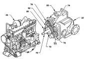
- FIG. 6is an exploded perspective view of a motor, compressor, and pump arrangement according to the present invention.
- FIG. 7is a top plan view of the motor, compressor, and pump arrangement according to the present invention.
- FIG. 8is a schematic diagram similar to FIG. 4 , pertaining to the present invention.
- FIG. 5Depicted in FIG. 5 is a drilling rig 30 on which the present invention is employed. That drilling rig is basically similar to that of FIG. 2 in terms of the overall equipment provided. That is, the drilling rig 30 includes a platform 12 to which a drivable ground support (e.g., tracks 14 or wheels) is attached. An operator's cab 16 is disposed at a rear end of the platform. Situated in front of the cab is a beam 18 whose lower end is connected to a fixed pedestal 18 a and is swingable about a horizontal axis between a vertical state to a horizontal state in which the free end of the beam sits on a rest 20 situated at the front of the platform.
- a drivable ground supporte.g., tracks 14 or wheels
- the beamcan be in the form of a mast which carries a carousel in which drill rods are stored.
- the mast 18is swung by hydraulic devices 21 to an upright state during a drilling operation and to a horizontal state for tramming to a new work site.
- Mounted on the mastis a hydraulic mechanism for raising or lowering drill rods and rotating the carousel.
- Pressurized hydraulic fluid for actuating the hydraulic devicesis provided by hydraulic pumps 50 , 52 .
- a conventional screw compressor 22is provided for providing compressed air to a drill bit in order to flush cuttings from a hole being drilled.
- the screw compressorcomprises a male (drive) screw and a female (driven) screw arranged to mesh with the male screw, as is conventional, e.g., see the conventional screw compressor depicted in copending Ser. No. 10/147,883, filed May 20, 2002, which is incorporated by reference herein.
- the compressed air from the screw compressoris stored in an air reservoir 19 ( FIG. 8 ) before being conducted to the drill string.
- a motor 26is provided for driving the screw compressor 22 and the hydraulic pumps 50 , 52 .
- the motor 26can be any suitable conventional type such as an electric motor or a fuel-driven engine (such as a diesel engine).
- a single gearbox 60that gearbox includes an outer casing 61 , having a flange 63 that is bolted to a flywheel housing 65 of the motor and forms an enclosed gear chamber.
- Each pump 50 , 52includes a flange 53 connected to the gearbox casing 61
- the compressor 22includes a flange 55 connected to the casing 61 .
- a drive shaft 70 driven by the enginedrives two coaxial drive gears 72 , 74 disposed in the gear chamber.
- a first of those gears 72constitutes a compressor drive gear in that it drives a gear 76 connected to a first of the screws of the compressor 22 ; that driver screw (male screw) then drives a second screw which meshes with the first screw. Air is compressed between the meshing screws.
- the hydraulic pumps 50 , 52also include respective input shafts to which are connected gears 78 , 80 respectively. Those gears are driven by the second drive gear 74 , which constitutes a pump drive gear.
- the gear ratio between the compressor drive gear 72 and the compressor input gear 76can be different than the gear ratio between the pump drive gear 74 and the pump input gears 78 , 80 , whereby the compressor can be driven at a different speed than the pumps.
- an oil input conduit 90extends from the reservoir 19 to the gearbox 60 and the compressor 22 for conducting lubricating oil into the gear chamber and the compressor.
- the oilis conventional compressor oil that is normally used in screw compressors and which is substantially less viscous than gear oil that is normally used to lubricate the gears of a pump.
- the compressor oilhas a viscosity grade no greater than about 1000 cSt at 30° F., and preferably is 750 cSt at 30° F. High pressure air, mixed with compressor oil, is conducted from the compressor 22 to the air reservoir 19 which separates the air from the oil.
- the separated compressor oilcan be conducted to the compressor and to the gear housing through the conduit 90 due to a difference in pressure between the reservoir 19 and the gearbox 60 .
- the compressor oiltogether with some pressurized air, is injected toward the meshing zones of the respective gears 72 , 74 , 76 , 78 , 80 .
- An oil output conduit 92extends from the gear chamber to the compressor inlet for conducting the oil/air from the gearbox to the compressor inlet.
- a light stream of cool, fresh compressor oilis continuously circulated through the gearbox 60 , and is sucked out of the gearbox by suction from the compressor or from a separate pump.
- the gearboxcan thus be called a “dry” gearbox.
- a separate suction pumpcould be used to suck the oil out of the gearbox.
- the pump gearing, as well as the compressor gearingis thereby lubricated in a manner which minimizes power losses, facilitates start-up and avoids the need for oil replacement, in contrast to conventional pump drive gearboxes which are flooded with much heavier gear oil, e.g., typically having a viscosity grade of about 20,000 cSt at 30° F.
- gearboxthat is common to the compressor and the pumps
- the advantageous lubrication technique commonly employed in compressor gearboxesis available to the pump gears as well.
- the engine 26can be provided with a disconnect such as a clutch between the flywheel and the gearbox, to facilitate starting of the engine in cold weather. It would also be possible to provide the hydraulic pumps and/or the compressor with respective clutches, but that is not preferred, in order to minimize the number of parts and maximize the robustness of the system.
- the length of the compressor/pump assemblycan be considerably shortened as compared to conventional assemblies, thereby providing enhanced versatility in locating the center of gravity of such an assembly along the longitudinal dimension of the rig platform. That, in turn, provides greater opportunity to optimize the location of the load on the ground support by centering, or nearly centering that center of gravity relative to the ground support tracks (or wheels).
Landscapes
- Engineering & Computer Science (AREA)
- General Engineering & Computer Science (AREA)
- Mechanical Engineering (AREA)
- Mining & Mineral Resources (AREA)
- Life Sciences & Earth Sciences (AREA)
- Geology (AREA)
- Fluid Mechanics (AREA)
- Environmental & Geological Engineering (AREA)
- Physics & Mathematics (AREA)
- General Life Sciences & Earth Sciences (AREA)
- Geochemistry & Mineralogy (AREA)
- Compressors, Vaccum Pumps And Other Relevant Systems (AREA)
- Earth Drilling (AREA)
- Details Of Reciprocating Pumps (AREA)
Abstract
Description
- to lubricate and cool the hydraulic pump gearings in a manner which reduces the power losses,
- to ease the difficult diesel engine start-ups,
- to eliminate the need for replacing the lubricating oil in the pump drive gear boxes,
- to eliminate expensive, complicated, high maintenance and cost items,
- to simplify the overall power train design and construction, and
- to reduce the size of the power unit comprised of the diesel engine, the compressor, and the hydraulic pumps
Claims (12)
Priority Applications (6)
| Application Number | Priority Date | Filing Date | Title |
|---|---|---|---|
| US10/259,308US6981855B2 (en) | 2002-09-30 | 2002-09-30 | Drilling rig having a compact compressor/pump assembly |
| JP2004541867AJP4417842B2 (en) | 2002-09-30 | 2003-09-30 | Drilling rig with compact assembly of compressor and pump |
| EP03799320AEP1546510A4 (en) | 2002-09-30 | 2003-09-30 | Drilling rig having a compact compressor/pump assembly |
| AU2003277066AAU2003277066B2 (en) | 2002-09-30 | 2003-09-30 | Drilling rig having a compact compressor/pump assembly |
| PCT/US2003/030746WO2004031528A2 (en) | 2002-09-30 | 2003-09-30 | Drilling rig having a compact compressor/pump assembly |
| ZA200503015AZA200503015B (en) | 2002-09-30 | 2005-04-14 | Drilling rig having a compact compressor/pump assembly |
Applications Claiming Priority (1)
| Application Number | Priority Date | Filing Date | Title |
|---|---|---|---|
| US10/259,308US6981855B2 (en) | 2002-09-30 | 2002-09-30 | Drilling rig having a compact compressor/pump assembly |
Publications (2)
| Publication Number | Publication Date |
|---|---|
| US20040060717A1 US20040060717A1 (en) | 2004-04-01 |
| US6981855B2true US6981855B2 (en) | 2006-01-03 |
Family
ID=32029478
Family Applications (1)
| Application Number | Title | Priority Date | Filing Date |
|---|---|---|---|
| US10/259,308Expired - LifetimeUS6981855B2 (en) | 2002-09-30 | 2002-09-30 | Drilling rig having a compact compressor/pump assembly |
Country Status (6)
| Country | Link |
|---|---|
| US (1) | US6981855B2 (en) |
| EP (1) | EP1546510A4 (en) |
| JP (1) | JP4417842B2 (en) |
| AU (1) | AU2003277066B2 (en) |
| WO (1) | WO2004031528A2 (en) |
| ZA (1) | ZA200503015B (en) |
Cited By (12)
| Publication number | Priority date | Publication date | Assignee | Title |
|---|---|---|---|---|
| US20090129956A1 (en)* | 2007-11-21 | 2009-05-21 | Jean-Louis Picouet | Compressor System and Method of Lubricating the Compressor System |
| US20090218142A1 (en)* | 2008-02-29 | 2009-09-03 | Forrest Burkholder | Method and system for helicopter portable drilling |
| US20090260357A1 (en)* | 2008-04-16 | 2009-10-22 | Gm Global Technology Operations, Inc. | Servo-actuated supercharger operating mechanism |
| WO2011043785A1 (en) | 2009-10-08 | 2011-04-14 | Atlas Copco Drilling Solutions Llc | Drilling machine power pack which includes a clutch |
| US20110127103A1 (en)* | 2007-08-09 | 2011-06-02 | Voith Patent Gmbh | Power steering pump drive |
| US20130011285A1 (en)* | 2005-12-08 | 2013-01-10 | Ghh Rand Schraubenkompressoren Gmbh | Three-stage screw compressor |
| US9010459B2 (en) | 2010-04-20 | 2015-04-21 | Sandvik Intellectual Property Ab | Air compressor system and method of operation |
| US20150275897A1 (en)* | 2012-09-21 | 2015-10-01 | Sandvik Surface Mining | Method and apparatus for decompressing a compressor |
| US10124844B2 (en) | 2015-04-28 | 2018-11-13 | Cnh Industrial America Llc | System and method for supplying fluid to a track drive box of a work vehicle |
| US10760456B2 (en) | 2012-01-05 | 2020-09-01 | Ford Global Technologies, Llc | Engine lubrication system |
| US11209002B2 (en)* | 2017-09-06 | 2021-12-28 | Joy Global Surface Mining Inc | Lubrication system for a compressor |
| US11680588B2 (en) | 2020-04-21 | 2023-06-20 | Joy Global Surface Mining Inc | Lubrication system for a compressor |
Families Citing this family (11)
| Publication number | Priority date | Publication date | Assignee | Title |
|---|---|---|---|---|
| DE102005016884A1 (en) | 2005-04-12 | 2006-10-19 | Wirth Maschinen- und Bohrgeräte-Fabrik GmbH | pump system |
| US8920146B2 (en) | 2005-04-12 | 2014-12-30 | Mhwirth Gmbh | Pump system |
| WO2007126477A2 (en) | 2006-03-30 | 2007-11-08 | Exxonmobil Upstream Research Company | Mobile, year-round arctic drilling system |
| US20090322732A1 (en)* | 2007-01-15 | 2009-12-31 | Matsushita Electric Industrial Co., Ltd. | Method for driving plasma display panel and plasma display device |
| SE531521C2 (en)* | 2007-09-07 | 2009-05-05 | Svenska Maskin Och Tryckluft I | Device for drilling in soil layers and rock |
| BRPI0912304B1 (en)* | 2008-06-04 | 2019-11-19 | Knorr Bremse Systeme Fuer Nutzfahrzeuge Gmbh | compressor system for supplying compressed air to a utility vehicle and process for operating a compressor system |
| CN102162333A (en)* | 2011-05-15 | 2011-08-24 | 石午江 | Fully-electric crawler suspension remote control pile driver |
| CN103362441B (en)* | 2012-04-08 | 2018-01-16 | 李立华 | A kind of new drill jumbo |
| CN104100200A (en)* | 2013-04-03 | 2014-10-15 | 郑州宇通重工有限公司 | Rotary drilling rig oil-electric double-power device |
| US11952893B2 (en) | 2019-12-20 | 2024-04-09 | Petróleo Brasiliero S. A.—Petrobras | Compact peripheral unit for onshore production rigs |
| WO2024211618A2 (en)* | 2023-04-05 | 2024-10-10 | Doosan Bobcat North America, Inc. | Secondary airflow paths for air compressors |
Citations (8)
| Publication number | Priority date | Publication date | Assignee | Title |
|---|---|---|---|---|
| US3809344A (en)* | 1971-12-08 | 1974-05-07 | Anlegg & Maskin As | Mobile drill rig |
| US4171188A (en)* | 1976-08-03 | 1979-10-16 | Chicago Pneumatic Tool Company | Rotary air compressors with intake valve control and lubrication system |
| US4315553A (en)* | 1980-08-25 | 1982-02-16 | Stallings Jimmie L | Continuous circulation apparatus for air drilling well bore operations |
| US4371041A (en)* | 1978-09-15 | 1983-02-01 | Drill Systems, Inc. | Multi-purpose mobile drill rig |
| US5697763A (en)* | 1993-10-29 | 1997-12-16 | Cash Engineering Research Pty Ltd | Tank mounted rotary compressor |
| US6478560B1 (en)* | 2000-07-14 | 2002-11-12 | Ingersoll-Rand Company | Parallel module rotary screw compressor and method |
| US6488488B2 (en)* | 1999-03-10 | 2002-12-03 | Ghh-Rand Schraubenkompressoren Gmbh | Rotary helical screw-type compressor having an intake filter and muffler |
| US6860730B2 (en)* | 2002-05-20 | 2005-03-01 | Driltech Mission, Llc | Methods and apparatus for unloading a screw compressor |
Family Cites Families (8)
| Publication number | Priority date | Publication date | Assignee | Title |
|---|---|---|---|---|
| CH416919A (en)* | 1963-04-03 | 1966-07-15 | Miroslav Ing Vlasak | Turbo compressor unit |
| US4086019A (en)* | 1974-01-31 | 1978-04-25 | Compair Industrial Limited | Transmission means for centrifugal compressors |
| DE2848030A1 (en)* | 1978-11-06 | 1980-05-14 | Gutehoffnungshuette Sterkrade | MULTI-STAGE COMPRESSOR |
| DE3801434A1 (en)* | 1988-01-20 | 1989-08-03 | Leybold Ag | MULTIPLE ANGLE GEARBOX |
| DE3923431A1 (en)* | 1989-07-15 | 1991-01-24 | Battenfeld Extrusionstech | GEARBOX FOR DOUBLE SCREW EXTRUDER |
| FR2660259B1 (en)* | 1990-03-27 | 1992-07-24 | Rockwell Cim | DEVICE FOR MOTORIZED CONTROL OF A SET OF ELEMENTS SUCH AS THE ADJUSTABLE PARTS OF A VEHICLE SEAT. |
| US5795136A (en)* | 1995-12-04 | 1998-08-18 | Sundstrand Corporation | Encapsulated rotary screw air compressor |
| US6009953A (en)* | 1997-02-25 | 2000-01-04 | Hale Products, Inc. | Foam pump system for firefighting apparatus |
- 2002
- 2002-09-30USUS10/259,308patent/US6981855B2/ennot_activeExpired - Lifetime
- 2003
- 2003-09-30EPEP03799320Apatent/EP1546510A4/ennot_activeWithdrawn
- 2003-09-30WOPCT/US2003/030746patent/WO2004031528A2/enactiveApplication Filing
- 2003-09-30AUAU2003277066Apatent/AU2003277066B2/ennot_activeCeased
- 2003-09-30JPJP2004541867Apatent/JP4417842B2/ennot_activeExpired - Fee Related
- 2005
- 2005-04-14ZAZA200503015Apatent/ZA200503015B/enunknown
Patent Citations (8)
| Publication number | Priority date | Publication date | Assignee | Title |
|---|---|---|---|---|
| US3809344A (en)* | 1971-12-08 | 1974-05-07 | Anlegg & Maskin As | Mobile drill rig |
| US4171188A (en)* | 1976-08-03 | 1979-10-16 | Chicago Pneumatic Tool Company | Rotary air compressors with intake valve control and lubrication system |
| US4371041A (en)* | 1978-09-15 | 1983-02-01 | Drill Systems, Inc. | Multi-purpose mobile drill rig |
| US4315553A (en)* | 1980-08-25 | 1982-02-16 | Stallings Jimmie L | Continuous circulation apparatus for air drilling well bore operations |
| US5697763A (en)* | 1993-10-29 | 1997-12-16 | Cash Engineering Research Pty Ltd | Tank mounted rotary compressor |
| US6488488B2 (en)* | 1999-03-10 | 2002-12-03 | Ghh-Rand Schraubenkompressoren Gmbh | Rotary helical screw-type compressor having an intake filter and muffler |
| US6478560B1 (en)* | 2000-07-14 | 2002-11-12 | Ingersoll-Rand Company | Parallel module rotary screw compressor and method |
| US6860730B2 (en)* | 2002-05-20 | 2005-03-01 | Driltech Mission, Llc | Methods and apparatus for unloading a screw compressor |
Cited By (20)
| Publication number | Priority date | Publication date | Assignee | Title |
|---|---|---|---|---|
| US9091268B2 (en)* | 2005-12-08 | 2015-07-28 | Ghh Rand Schraubenkompressoren Gmbh | Three-stage screw compressor |
| US20130011285A1 (en)* | 2005-12-08 | 2013-01-10 | Ghh Rand Schraubenkompressoren Gmbh | Three-stage screw compressor |
| US20110127103A1 (en)* | 2007-08-09 | 2011-06-02 | Voith Patent Gmbh | Power steering pump drive |
| US20090129956A1 (en)* | 2007-11-21 | 2009-05-21 | Jean-Louis Picouet | Compressor System and Method of Lubricating the Compressor System |
| US20090218142A1 (en)* | 2008-02-29 | 2009-09-03 | Forrest Burkholder | Method and system for helicopter portable drilling |
| US20090260357A1 (en)* | 2008-04-16 | 2009-10-22 | Gm Global Technology Operations, Inc. | Servo-actuated supercharger operating mechanism |
| US7909026B2 (en)* | 2008-04-16 | 2011-03-22 | Gm Global Technology Operations, Inc. | Servo-actuated supercharger operating mechanism |
| WO2011043785A1 (en) | 2009-10-08 | 2011-04-14 | Atlas Copco Drilling Solutions Llc | Drilling machine power pack which includes a clutch |
| US20110083903A1 (en)* | 2009-10-08 | 2011-04-14 | Atlas Copco Drilling Solutions Llc | Drilling machine power pack which includes a clutch |
| US8646549B2 (en) | 2009-10-08 | 2014-02-11 | Atlas Copco Drilling Solutions Llc | Drilling machine power pack which includes a clutch |
| US9708855B2 (en) | 2009-10-08 | 2017-07-18 | Allas Copco Drilling Solutions, LLC | Drilling machine power pack which includes a clutch |
| US9011107B2 (en) | 2010-04-20 | 2015-04-21 | Sandvik Intellectual Property Ab | Air compressor system and method of operation |
| US9341177B2 (en) | 2010-04-20 | 2016-05-17 | Sandvik Intellectual Property Ab | Air compressor system and method of operation |
| US9010459B2 (en) | 2010-04-20 | 2015-04-21 | Sandvik Intellectual Property Ab | Air compressor system and method of operation |
| US9856875B2 (en) | 2010-04-20 | 2018-01-02 | Sandvik Intellectual Property Ab | Air compressor system and method of operation |
| US10760456B2 (en) | 2012-01-05 | 2020-09-01 | Ford Global Technologies, Llc | Engine lubrication system |
| US20150275897A1 (en)* | 2012-09-21 | 2015-10-01 | Sandvik Surface Mining | Method and apparatus for decompressing a compressor |
| US10124844B2 (en) | 2015-04-28 | 2018-11-13 | Cnh Industrial America Llc | System and method for supplying fluid to a track drive box of a work vehicle |
| US11209002B2 (en)* | 2017-09-06 | 2021-12-28 | Joy Global Surface Mining Inc | Lubrication system for a compressor |
| US11680588B2 (en) | 2020-04-21 | 2023-06-20 | Joy Global Surface Mining Inc | Lubrication system for a compressor |
Also Published As
| Publication number | Publication date |
|---|---|
| ZA200503015B (en) | 2006-08-30 |
| JP4417842B2 (en) | 2010-02-17 |
| EP1546510A4 (en) | 2006-01-04 |
| AU2003277066B2 (en) | 2010-04-29 |
| EP1546510A2 (en) | 2005-06-29 |
| WO2004031528A3 (en) | 2004-07-08 |
| AU2003277066A1 (en) | 2004-04-23 |
| WO2004031528A2 (en) | 2004-04-15 |
| JP2006501404A (en) | 2006-01-12 |
| US20040060717A1 (en) | 2004-04-01 |
Similar Documents
| Publication | Publication Date | Title |
|---|---|---|
| US6981855B2 (en) | Drilling rig having a compact compressor/pump assembly | |
| JP2006501404A5 (en) | ||
| US9853523B2 (en) | Wheel motor cooling system with equally divided flow | |
| US6860358B1 (en) | Utility vehicle having hydrostatic drive | |
| CN112610682A (en) | Active lubricating and cooling system for new energy automobile transmission | |
| CN217300455U (en) | Power unit of horizontal core drilling machine for mine | |
| CN116518036A (en) | Gearbox assembly for dual-motor driving engineering machinery | |
| CN216045332U (en) | Axle gear box | |
| CN214832657U (en) | Four-eccentric vibration exciter matched with forced lubrication | |
| US11680588B2 (en) | Lubrication system for a compressor | |
| CN213743390U (en) | Cutting part and heading machine | |
| CN220082043U (en) | Gearbox assembly for dual-motor driving engineering machinery | |
| CN2506476Y (en) | Four output end power transer case | |
| JPS6241986A (en) | Oil-free screw compressor combination | |
| CN218440444U (en) | Lightweight speed reducer for petroleum pump truck | |
| US3254735A (en) | Self-propelled reciprocating pumps with selective drive to wheels and pump | |
| CN218953244U (en) | Compact type rock drilling trolley for tunnel construction | |
| CN215171988U (en) | Four-shaft vibration box for resonance crusher | |
| CN221525043U (en) | Low Wen Chezai drilling pump single unit and duplex unit sharing power with chassis | |
| CN223004104U (en) | New energy motor electric control integrated drilling mud pump set | |
| CN222527372U (en) | Independent lubricating device for core drill power box | |
| CN217712842U (en) | Single-machine double-pump structure and working machine | |
| CN217538929U (en) | High-pressure large-flow emulsion pump | |
| CN217107559U (en) | Integrated centrifugal compressor casing | |
| CN214465868U (en) | Four-shaft gear box for resonance crusher |
Legal Events
| Date | Code | Title | Description |
|---|---|---|---|
| AS | Assignment | Owner name:SANDVIK AB, SWEDEN Free format text:ASSIGNMENT OF ASSIGNORS INTEREST;ASSIGNOR:LEPPANEN, JARMO;REEL/FRAME:013492/0373 Effective date:20021023 | |
| AS | Assignment | Owner name:SANDVIK INTELLECTUAL PROPERTY HB, SWEDEN Free format text:ASSIGNMENT OF ASSIGNORS INTEREST;ASSIGNOR:SANDVIK AB;REEL/FRAME:016290/0628 Effective date:20050516 Owner name:SANDVIK INTELLECTUAL PROPERTY HB,SWEDEN Free format text:ASSIGNMENT OF ASSIGNORS INTEREST;ASSIGNOR:SANDVIK AB;REEL/FRAME:016290/0628 Effective date:20050516 | |
| AS | Assignment | Owner name:SANDVIK INTELLECTUAL PROPERTY AKTIEBOLAG, SWEDEN Free format text:ASSIGNMENT OF ASSIGNORS INTEREST;ASSIGNOR:SANDVIK INTELLECTUAL PROPERTY HB;REEL/FRAME:016621/0366 Effective date:20050630 Owner name:SANDVIK INTELLECTUAL PROPERTY AKTIEBOLAG,SWEDEN Free format text:ASSIGNMENT OF ASSIGNORS INTEREST;ASSIGNOR:SANDVIK INTELLECTUAL PROPERTY HB;REEL/FRAME:016621/0366 Effective date:20050630 | |
| STCF | Information on status: patent grant | Free format text:PATENTED CASE | |
| AS | Assignment | Owner name:QUANTUM CORPORATION, CALIFORNIA Free format text:RELEASE OF INTELLECTUAL PROPERTY SECURITY AGREEMENT AT REEL 018303 FRAME 0282;ASSIGNOR:KEYBANK NATIONAL ASSOCIATION;REEL/FRAME:019573/0001 Effective date:20070712 | |
| FPAY | Fee payment | Year of fee payment:4 | |
| FPAY | Fee payment | Year of fee payment:8 | |
| FPAY | Fee payment | Year of fee payment:12 |