US6981518B2 - Latching micro-regulator - Google Patents
Latching micro-regulatorDownload PDFInfo
- Publication number
- US6981518B2 US6981518B2US10/179,537US17953702AUS6981518B2US 6981518 B2US6981518 B2US 6981518B2US 17953702 AUS17953702 AUS 17953702AUS 6981518 B2US6981518 B2US 6981518B2
- Authority
- US
- United States
- Prior art keywords
- flow
- valve
- flow channel
- chamber
- stable
- Prior art date
- Legal status (The legal status is an assumption and is not a legal conclusion. Google has not performed a legal analysis and makes no representation as to the accuracy of the status listed.)
- Expired - Lifetime, expires
Links
Images


Classifications
- F—MECHANICAL ENGINEERING; LIGHTING; HEATING; WEAPONS; BLASTING
- F16—ENGINEERING ELEMENTS AND UNITS; GENERAL MEASURES FOR PRODUCING AND MAINTAINING EFFECTIVE FUNCTIONING OF MACHINES OR INSTALLATIONS; THERMAL INSULATION IN GENERAL
- F16K—VALVES; TAPS; COCKS; ACTUATING-FLOATS; DEVICES FOR VENTING OR AERATING
- F16K99/00—Subject matter not provided for in other groups of this subclass
- F16K99/0001—Microvalves
- F—MECHANICAL ENGINEERING; LIGHTING; HEATING; WEAPONS; BLASTING
- F15—FLUID-PRESSURE ACTUATORS; HYDRAULICS OR PNEUMATICS IN GENERAL
- F15C—FLUID-CIRCUIT ELEMENTS PREDOMINANTLY USED FOR COMPUTING OR CONTROL PURPOSES
- F15C5/00—Manufacture of fluid circuit elements; Manufacture of assemblages of such elements integrated circuits
- F—MECHANICAL ENGINEERING; LIGHTING; HEATING; WEAPONS; BLASTING
- F16—ENGINEERING ELEMENTS AND UNITS; GENERAL MEASURES FOR PRODUCING AND MAINTAINING EFFECTIVE FUNCTIONING OF MACHINES OR INSTALLATIONS; THERMAL INSULATION IN GENERAL
- F16K—VALVES; TAPS; COCKS; ACTUATING-FLOATS; DEVICES FOR VENTING OR AERATING
- F16K99/00—Subject matter not provided for in other groups of this subclass
- F16K99/0001—Microvalves
- F16K99/0003—Constructional types of microvalves; Details of the cutting-off member
- F16K99/0005—Lift valves
- F16K99/0007—Lift valves of cantilever type
- F—MECHANICAL ENGINEERING; LIGHTING; HEATING; WEAPONS; BLASTING
- F16—ENGINEERING ELEMENTS AND UNITS; GENERAL MEASURES FOR PRODUCING AND MAINTAINING EFFECTIVE FUNCTIONING OF MACHINES OR INSTALLATIONS; THERMAL INSULATION IN GENERAL
- F16K—VALVES; TAPS; COCKS; ACTUATING-FLOATS; DEVICES FOR VENTING OR AERATING
- F16K99/00—Subject matter not provided for in other groups of this subclass
- F16K99/0001—Microvalves
- F16K99/0003—Constructional types of microvalves; Details of the cutting-off member
- F16K99/0005—Lift valves
- F16K99/0009—Lift valves the valve element held by multiple arms
- F—MECHANICAL ENGINEERING; LIGHTING; HEATING; WEAPONS; BLASTING
- F16—ENGINEERING ELEMENTS AND UNITS; GENERAL MEASURES FOR PRODUCING AND MAINTAINING EFFECTIVE FUNCTIONING OF MACHINES OR INSTALLATIONS; THERMAL INSULATION IN GENERAL
- F16K—VALVES; TAPS; COCKS; ACTUATING-FLOATS; DEVICES FOR VENTING OR AERATING
- F16K99/00—Subject matter not provided for in other groups of this subclass
- F16K99/0001—Microvalves
- F16K99/0003—Constructional types of microvalves; Details of the cutting-off member
- F16K99/0015—Diaphragm or membrane valves
- F—MECHANICAL ENGINEERING; LIGHTING; HEATING; WEAPONS; BLASTING
- F16—ENGINEERING ELEMENTS AND UNITS; GENERAL MEASURES FOR PRODUCING AND MAINTAINING EFFECTIVE FUNCTIONING OF MACHINES OR INSTALLATIONS; THERMAL INSULATION IN GENERAL
- F16K—VALVES; TAPS; COCKS; ACTUATING-FLOATS; DEVICES FOR VENTING OR AERATING
- F16K99/00—Subject matter not provided for in other groups of this subclass
- F16K99/0001—Microvalves
- F16K99/0034—Operating means specially adapted for microvalves
- F16K99/0042—Electric operating means therefor
- F16K99/0046—Electric operating means therefor using magnets
- F—MECHANICAL ENGINEERING; LIGHTING; HEATING; WEAPONS; BLASTING
- F16—ENGINEERING ELEMENTS AND UNITS; GENERAL MEASURES FOR PRODUCING AND MAINTAINING EFFECTIVE FUNCTIONING OF MACHINES OR INSTALLATIONS; THERMAL INSULATION IN GENERAL
- F16K—VALVES; TAPS; COCKS; ACTUATING-FLOATS; DEVICES FOR VENTING OR AERATING
- F16K99/00—Subject matter not provided for in other groups of this subclass
- F16K99/0001—Microvalves
- F16K99/0034—Operating means specially adapted for microvalves
- F16K99/0042—Electric operating means therefor
- F16K99/0048—Electric operating means therefor using piezoelectric means
- G—PHYSICS
- G05—CONTROLLING; REGULATING
- G05D—SYSTEMS FOR CONTROLLING OR REGULATING NON-ELECTRIC VARIABLES
- G05D7/00—Control of flow
- G05D7/06—Control of flow characterised by the use of electric means
- G05D7/0617—Control of flow characterised by the use of electric means specially adapted for fluid materials
- G05D7/0629—Control of flow characterised by the use of electric means specially adapted for fluid materials characterised by the type of regulator means
- G05D7/0694—Control of flow characterised by the use of electric means specially adapted for fluid materials characterised by the type of regulator means by action on throttling means or flow sources of very small size, e.g. microfluidics
- F—MECHANICAL ENGINEERING; LIGHTING; HEATING; WEAPONS; BLASTING
- F16—ENGINEERING ELEMENTS AND UNITS; GENERAL MEASURES FOR PRODUCING AND MAINTAINING EFFECTIVE FUNCTIONING OF MACHINES OR INSTALLATIONS; THERMAL INSULATION IN GENERAL
- F16K—VALVES; TAPS; COCKS; ACTUATING-FLOATS; DEVICES FOR VENTING OR AERATING
- F16K99/00—Subject matter not provided for in other groups of this subclass
- F16K99/0001—Microvalves
- F16K2099/0069—Bistable microvalves
- F—MECHANICAL ENGINEERING; LIGHTING; HEATING; WEAPONS; BLASTING
- F16—ENGINEERING ELEMENTS AND UNITS; GENERAL MEASURES FOR PRODUCING AND MAINTAINING EFFECTIVE FUNCTIONING OF MACHINES OR INSTALLATIONS; THERMAL INSULATION IN GENERAL
- F16K—VALVES; TAPS; COCKS; ACTUATING-FLOATS; DEVICES FOR VENTING OR AERATING
- F16K99/00—Subject matter not provided for in other groups of this subclass
- F16K99/0001—Microvalves
- F16K2099/0071—Microvalves with latching means
- F—MECHANICAL ENGINEERING; LIGHTING; HEATING; WEAPONS; BLASTING
- F16—ENGINEERING ELEMENTS AND UNITS; GENERAL MEASURES FOR PRODUCING AND MAINTAINING EFFECTIVE FUNCTIONING OF MACHINES OR INSTALLATIONS; THERMAL INSULATION IN GENERAL
- F16K—VALVES; TAPS; COCKS; ACTUATING-FLOATS; DEVICES FOR VENTING OR AERATING
- F16K99/00—Subject matter not provided for in other groups of this subclass
- F16K2099/0073—Fabrication methods specifically adapted for microvalves
- F16K2099/0074—Fabrication methods specifically adapted for microvalves using photolithography, e.g. etching
- F—MECHANICAL ENGINEERING; LIGHTING; HEATING; WEAPONS; BLASTING
- F16—ENGINEERING ELEMENTS AND UNITS; GENERAL MEASURES FOR PRODUCING AND MAINTAINING EFFECTIVE FUNCTIONING OF MACHINES OR INSTALLATIONS; THERMAL INSULATION IN GENERAL
- F16K—VALVES; TAPS; COCKS; ACTUATING-FLOATS; DEVICES FOR VENTING OR AERATING
- F16K99/00—Subject matter not provided for in other groups of this subclass
- F16K2099/0073—Fabrication methods specifically adapted for microvalves
- F16K2099/0076—Fabrication methods specifically adapted for microvalves using electrical discharge machining [EDM], milling or drilling
- F—MECHANICAL ENGINEERING; LIGHTING; HEATING; WEAPONS; BLASTING
- F16—ENGINEERING ELEMENTS AND UNITS; GENERAL MEASURES FOR PRODUCING AND MAINTAINING EFFECTIVE FUNCTIONING OF MACHINES OR INSTALLATIONS; THERMAL INSULATION IN GENERAL
- F16K—VALVES; TAPS; COCKS; ACTUATING-FLOATS; DEVICES FOR VENTING OR AERATING
- F16K99/00—Subject matter not provided for in other groups of this subclass
- F16K2099/0073—Fabrication methods specifically adapted for microvalves
- F16K2099/008—Multi-layer fabrications
- F—MECHANICAL ENGINEERING; LIGHTING; HEATING; WEAPONS; BLASTING
- F16—ENGINEERING ELEMENTS AND UNITS; GENERAL MEASURES FOR PRODUCING AND MAINTAINING EFFECTIVE FUNCTIONING OF MACHINES OR INSTALLATIONS; THERMAL INSULATION IN GENERAL
- F16K—VALVES; TAPS; COCKS; ACTUATING-FLOATS; DEVICES FOR VENTING OR AERATING
- F16K99/00—Subject matter not provided for in other groups of this subclass
- F16K2099/0082—Microvalves adapted for a particular use
- F16K2099/0084—Chemistry or biology, e.g. "lab-on-a-chip" technology
- Y—GENERAL TAGGING OF NEW TECHNOLOGICAL DEVELOPMENTS; GENERAL TAGGING OF CROSS-SECTIONAL TECHNOLOGIES SPANNING OVER SEVERAL SECTIONS OF THE IPC; TECHNICAL SUBJECTS COVERED BY FORMER USPC CROSS-REFERENCE ART COLLECTIONS [XRACs] AND DIGESTS
- Y10—TECHNICAL SUBJECTS COVERED BY FORMER USPC
- Y10T—TECHNICAL SUBJECTS COVERED BY FORMER US CLASSIFICATION
- Y10T137/00—Fluid handling
- Y10T137/8593—Systems
- Y10T137/87265—Dividing into parallel flow paths with recombining
- Y10T137/87298—Having digital flow controller
- Y10T137/87306—Having plural branches under common control for separate valve actuators
- Y10T137/87314—Electromagnetic or electric control [e.g., digital control, bistable electro control, etc.]
- Y—GENERAL TAGGING OF NEW TECHNOLOGICAL DEVELOPMENTS; GENERAL TAGGING OF CROSS-SECTIONAL TECHNOLOGIES SPANNING OVER SEVERAL SECTIONS OF THE IPC; TECHNICAL SUBJECTS COVERED BY FORMER USPC CROSS-REFERENCE ART COLLECTIONS [XRACs] AND DIGESTS
- Y10—TECHNICAL SUBJECTS COVERED BY FORMER USPC
- Y10T—TECHNICAL SUBJECTS COVERED BY FORMER US CLASSIFICATION
- Y10T29/00—Metal working
- Y10T29/49—Method of mechanical manufacture
- Y10T29/49405—Valve or choke making
- Y10T29/49412—Valve or choke making with assembly, disassembly or composite article making
Definitions
- the present inventionrelates to a micro-regulator and a bi-stable latching valve for regulating fluid flow on micro-scale dimensions.
- Microfluidic devices and systemsprovide improved methods of performing chemical, biochemical and biological analysis and synthesis. Microfluidic devices and systems allow for the performance of multi-step, multi-species chemical operations in chip-based micro chemical analysis systems.
- Chip-based microfluidic systemsgenerally comprise conventional ‘microfluidic’ elements, particularly capable of handling and analyzing chemical and biological specimens.
- microfluidic in the artrefers to systems or devices having a network of processing nodes, chambers and reservoirs connected by channels, in which the channels have typical cross-sectional dimensions in the range between about 1.0 ⁇ m and about 500 ⁇ m. In the art, channels having these cross-sectional dimensions are referred to as ‘microchannels’.
- Downscaling dimensionsallows for diffusional processes, such as heating, cooling and passive transport of species (diffusional mass-transport), to proceed faster.
- diffusional processessuch as heating, cooling and passive transport of species (diffusional mass-transport)
- thermal processing of liquidswhich is typically a required step in chemical synthesis and analysis.
- thermal processing of liquidsis accelerated in a microchannel due to reduced diffusional distances.
- Another example of the efficiency of microfluidic systemsis the mixing of dissolved species in a liquid, a process that is also diffusion limited.
- Milliliter-sized systemstypically require milliliter volumes of these substances, while microliter sized microfluidic systems only require microliter volumes.
- the ability to perform these processes using smaller volumesresults in significant cost savings, allowing the economic operation of chemical synthesis and analysis operations.
- the amount of chemical waste produced during the chemical operationsis correspondingly reduced.
- a flow control devicemay be used to regulate, allow or halt the flow of liquid through a microchannel, either manually or automatically. Regulation includes control of flow rate, impeding of flow, switching of flows between various input channels and output channels, as well as volumetric dosing. It is generally desirable that flow control devices, such as valves, precisely and accurately regulates fluid flow, while being economical to manufacture.
- the present inventionprovides a latching micro-regulator for regulating liquid flow on micro-scale levels.
- the latching micro-regulatorprovides binary addressable flow control using digital latching.
- the latching micro-regulatorincludes a bi-stable latching valve comprising a substrate having an inlet port and an outlet port, a valve seat defining a valve chamber for opening and closing the inlet port, and an actuator assembly for actuating the valve element.
- the valve chamberis configured to contain a volume of fluid, and the inlet port and the outlet port are in fluid communication with the valve chamber to provide a liquid flow path through the chamber.
- the actuator assemblycomprises a cantilever beam for moving the valve seat between an open position and a closed position, an actuator, such as a piezoelectric element, for moving the cantilever beam, and a latch, such as a permanent magnet, for securing the cantilever beam in the closed position.
- a bi-stable latching valvefor controlling fluid flow through a channel.
- the bi-stable latching valvecomprises a substrate defining an inlet port and an outlet port in communication with the channel, a valve seat, an actuator assembly for selectively moving the valve seat between the open position and the closed position and a latching mechanism.
- the valve seatdefines a valve chamber in communication with the inlet port and the outlet port for containing a volume of fluid and the valve seat moves between a closed position wherein the valve seat blocks one of said inlet port and said outlet port and an open position to allow fluid flow through the valve chamber to regulate fluid flow through the chamber.
- the latching mechanismlatches the valve seat in one of said open position and closed position.
- a flow regulating systemcomprises a first flow channel for conveying liquids having a first flow resistance, a first bi-stable valve in communication with the first flow channel for selectively blocking liquid flow through the first flow channel, a second flow channel for conveying liquids having a second flow resistance and a second bi-stable valve in communication with the second flow channel for selectively blocking liquid flow through the second flow channel.
- a flow regulating systemcomprises a first flow channel for conveying liquids having a first flow resistance, a first bi-stable latching valve in communication with the first flow channel for selectively blocking liquid flow through the first flow channel, a second flow channel for conveying liquids having a second flow resistance and a second bi-stable latching valve in communication with the second flow channel for selectively blocking liquid flow through the second flow channel.
- the first and second bi-stable latching valveeach comprise a piezoelectric actuator for selectively opening and blocking the flow channel, and a magnetic latch for locking the valve in a closed position.
- FIG. 1is a cross-sectional side view of an embodiment of the bi-stable latching valve of the present invention.
- FIG. 2 ais a detailed side view of the bi-stable latching valve of FIG. 1 in an open position.
- FIG. 2 bis a top view of the bi-stable latching valve of FIG. 2 a.
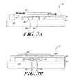
- FIGS. 3 a and 3 billustrate the bi-stable latching valve switching from a closed position to an open position.
- FIGS. 4 a and 4 billustrate the bi-stable latching valve switching from an open position to a closed position.
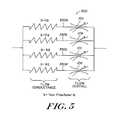
- FIG. 5is a schematic diagram of a flow regulating system for a microfluidic system implementing a plurality of bi-stable latching valves according to an illustrative embodiment of the invention to provide variable control of fluid flow.
- the present inventionprovides a digital latching micro-regulator including a bi-stable latching valve for accurately controlling fluid flow on demand.
- the present inventionwill be described below relative to an illustrative embodiment. Those skilled in the art will appreciate that the present invention may be implemented in a number of different applications and embodiments and is not specifically limited in its application to the particular embodiments depicted herein.
- the present inventionprovides a bi-stable latching valve for selectively blocking fluid flow through a channel.
- the valveis positioned in a channel to selectively block liquid flow through the channel.
- the bi-stable latching valve 10 of the present inventioncomprises a substrate 20 having an inlet port 22 and an outlet port 24 formed therein in fluid communication with a channel through which liquid flows.
- the substrate 20is preferably formed of glass or plastic, though other materials may be used.
- the bi-stable latching valve 10further includes a valve seat 30 cooperating with the substrate to define a valve chamber 26 in communication with the inlet port 22 and the outlet port 24 for containing a volume of fluid.
- the valve seat 30selectively blocks the inlet port 22 to regulate the flow of fluid into the chamber 26 .
- the position of the valve seat 30controls the fluid flow into the chamber 26 .
- the position of the valve seat 30is controlled by an actuator assembly 50 .
- the actuator assemblycan comprise any suitable structure for selectively operating or moving the valve seat 30 to block the inlet port 22 or the outlet port 24 .
- the actuator assemblyincludes a cantilever beam 40 hinged to the substrate 20 , an actuator 52 , and a latching mechanism 60 .
- the position of the valve seat 30is determined by the position of the cantilever beam 40 .
- the valve seat 30is connected to the cantilever beam 40 , which is in turn connected to the actuator 52 .
- the actuator 52can comprise any suitable structure for moving the valve seat 30 between an open position for allowing fluid to enter or exit the chamber, and a closed position. Examples of suitable actuators include mechanical, electrical, electromechanical, and magnetic devices. According to a preferred embodiment, the actuator 52 is a piezoelectric element.
- the cantilever beam 40is hinged at a first end 41 to the glass substrate 20 and rotates about the fixed hinge under the control of the actuator 52 to move the valve seat 30 between the open and closed positions.
- the cantilever beam 40When the cantilever beam 40 is lowered, the beam pushes the valve seat 30 into a closed position, thereby blocking the inlet port and preventing fluid flow into the chamber. When the cantilever beam 40 is raised, the valve 30 is moved to an open position to allow fluid flow through the chamber 26 .
- the cantilever beam 40is driven by the piezoelectric element 52 , which selectively applies a driving force to the beam 40 .
- the bi-stable latching valve 10further includes a latching mechanism 60 for selectively latching or holding the beam 40 in a selected position.
- the latching mechanismcan include any suitable mechanical, electrical, electromechanical or magnetic structure suitable for latching the beam 40 .
- the latching mechanism 60comprises a permanent magnet 62 and a permalloy element 46 disposed on a free end 44 of the beam 40 .
- the permanent magnet 62is attached to the glass substrate 20 opposite the permalloy element 46 and is configured to attract the permalloy element 46 .
- the magnetic attraction between the permanent magnet and the permalloy elementis effective to latch, i.e. to retain, the valve element in a closed position to prevent fluid flow through the bistable latching valve 10 .
- the valve seat 30is cylindrical in shape and includes a rim 38 about the circumference of the valve seat 30 , which defines the valve chamber 26 .
- the rim 38cooperates with the glass substrate 20 to fluidly seal the valve chamber 26 .
- the valve chambercommunicates with the inlet port 22 and the outlet port 24 .
- the valve seat 30is preferably formed of a flexible material, such as silicone rubber, though one skilled the art will recognize that alternate materials may be used.
- the valve seat 30further comprises a membrane portion 32 , a first protrusion 34 for contacting the cantilever beam 40 and second protrusion 36 for selectively blocking the inlet port 22 to prevent the flow of fluid through the valve chamber 26 , thereby blocking fluid flow through the associated channel.
- valve seat 30is not limited to a cylindrical shape, and that any suitable shape may be utilized.
- the operation of the bi-stable latching valve 10is illustrated in FIGS. 3 a - 3 b and FIGS. 4 a - 4 b .
- the bi-stable latching valve 10switches between two stable states: an ON state, which allows the flow of liquid through the valve chamber and an OFF state, which prevents the flow of liquid through the valve chamber.
- the state of the bi-stable latching valve 10is controlled by the driving force on the cantilever beam 40 by the actuator 52 and the magnetic latching force created by the permanent magnet 62 on the beam free end.
- the bi-stable latching valveonly requires power to switch between the two stable states and does not otherwise require power to operate.
- FIG. 3 aillustrates the bi-stable latching valve 10 in an OFF state, where the second protrusion 36 of the valve seat 30 blocks the inlet port 22 so that fluid is prevented from flowing through the valve chamber 26 .
- the latching mechanism 60latches the cantilever beam 40 in the closed position by securing the permalloy element 46 to the permanent magnet 60 .
- the attractive force of the magnetpulls the cantilever beam towards the magnet, causing the cantilever beam to push the valve into the closed position, such that the first protrusion blocks the inlet port.
- the valvemaintains the closed position until activated.
- a voltageis applied to the piezoelectric element 52 using a controller (not shown).
- the applied voltagecauses the piezoelectric element to compress, applying an opposite force on the cantilever beam in the direction away from the magnet. If the force generated is sufficient to overcome the magnetic attraction between the magnet and the permalloy, the magnet releases the permalloy element and the cantilever beam raises, pulling the valve seat 30 clear of the inlet port 22 . As shown in FIG. 3 b , fluid flows through unobstructed inlet port 22 into the valve chamber and out of the valve chamber via the outlet port.
- the bi-stable latching valve 10remains in the ON state, as shown in FIG. 4 a , until the controller subsequently actuates the piezoelectric element 52 by applying a second voltage.
- the second voltagecauses the piezoelectric element to expand, which applies a driving force on the cantilever beam 40 , pushing the beam towards the magnet 60 .
- the lowered beamin turn applies a force to the valve seat 30 , which shifts into a closed position, blocking the inlet port.
- a magnetic latching force generated by the magnetlatches the beam 40 into the closed position until a subsequent actuation of the piezoelectric element 52 .
- the bi-stable latching valve 10may be employed in a valve architecture to provide binary addressable flow control using digital latching. As shown in FIG. 5 , multiple bistable latching valves may be connected to channels 550 of specific flow conductance that vary according to a pre-determined ratio to provide a micro-regulator 500 . Each bi-stable latching valve 10 can be set to an on or off state as described previously, allowing or blocking flow through its associated flow channel 550 . The bi-stable latching valves are selectively activated in various combinations to provide a number of discrete flow conductance states through the micro-regulator 500 . The net flow through the micro-regulator is therefore determined by the sum of the flows through the open bi-stable latching valves 10 . The number of discrete flow conductance states is determined by the number of bi-stable latching valves in the system and the flow conductance ratios between the channels.
- FIG. 5A typical example of a 4-bit micro-regulator system is illustrated in FIG. 5 .
- the individual channels 550 a , 550 b , 550 c and 550 d in the systemhave flow conductance ratios of 1:2:4:8, thus providing 16 discrete net flow conductance states.
- a first flow conductance statemay be provided by opening all of the bi-stable latching valves 10 a - 10 d to allow flow through all of the channels 550 a , 550 b , 550 c and 550 d .
- a second flow conductance stateis achieved by closing the first bi-stable latching valve 10 a , while leaving the remaining bi-stable latching valves 10 b , 10 c , 10 d open, allowing fluid flow through the channels 550 b , 550 c and 550 d only.
- a third conductance stateis achieved by closing the first and second bi-stable latching valves 10 a , 10 b while leaving the remaining bi-stable latching valves 10 c , 10 d to allow flow through the associated channels 550 c and 550 d , and so on. This allows flow rates to be controlled to a 6.67% precision. Higher precision can be obtained by increasing the number of bits in the system—for example an 8-bit system has 128 discrete states, achieving less than 1% precision in the flow rate control.
- any suitable bi-stable valve for selectively blocking liquid flow through a channelmay be used in the flow regulating system 500 of FIG. 5 to provide variable flow resistance.
- the micro-regulator 500may have any suitable number of channels arranged in any suitable configuration and having any suitable flow resistance to achieve a system having variable flow resistance, wherein the flow resistance depends on the state of the bi-stable valves.
- the manufacturing process for the bi-stable latching valve 10 of an illustrative embodiment of the present inventionis efficient, economical and simplified.
- the valve seat 30may be formed by surface micromachining of a substrate, followed by deposition of silicone rubber, the permalloy element 46 and polysilicon.
- the substrate 20is etched to form a channel and then drilled to form the inlet port 22 and the outlet port 24 .
- the cantilever beam 40may be attached and hinged to the glass substrate through means known in the art.
- the permalloy elementmay be bonded to the beam and the permanent magnet 62 may be bonded to the substrate through means known in the art.
- the piezoelectric element 52 or other actuator for driving the cantilever beam 40may be attached to the beam through any suitable means.
Landscapes
- Engineering & Computer Science (AREA)
- General Engineering & Computer Science (AREA)
- Dispersion Chemistry (AREA)
- Mechanical Engineering (AREA)
- Chemical & Material Sciences (AREA)
- Physics & Mathematics (AREA)
- Microelectronics & Electronic Packaging (AREA)
- Theoretical Computer Science (AREA)
- Fluid Mechanics (AREA)
- Computer Hardware Design (AREA)
- General Physics & Mathematics (AREA)
- Automation & Control Theory (AREA)
- Electrically Driven Valve-Operating Means (AREA)
- Magnetically Actuated Valves (AREA)
Abstract
Description
Claims (6)
Priority Applications (4)
| Application Number | Priority Date | Filing Date | Title |
|---|---|---|---|
| US10/179,537US6981518B2 (en) | 2002-03-15 | 2002-06-24 | Latching micro-regulator |
| US11/099,014US7134639B2 (en) | 2002-03-15 | 2005-04-04 | Latching micro-regulator |
| US11/591,213US7293581B2 (en) | 2002-03-15 | 2006-11-01 | Latching micro-regulator |
| US11/973,266US20080086885A1 (en) | 2002-03-15 | 2007-10-05 | Latching micro-regulator |
Applications Claiming Priority (2)
| Application Number | Priority Date | Filing Date | Title |
|---|---|---|---|
| US36480302P | 2002-03-15 | 2002-03-15 | |
| US10/179,537US6981518B2 (en) | 2002-03-15 | 2002-06-24 | Latching micro-regulator |
Related Child Applications (1)
| Application Number | Title | Priority Date | Filing Date |
|---|---|---|---|
| US11/099,014DivisionUS7134639B2 (en) | 2002-03-15 | 2005-04-04 | Latching micro-regulator |
Publications (2)
| Publication Number | Publication Date |
|---|---|
| US20030172975A1 US20030172975A1 (en) | 2003-09-18 |
| US6981518B2true US6981518B2 (en) | 2006-01-03 |
Family
ID=28044409
Family Applications (4)
| Application Number | Title | Priority Date | Filing Date |
|---|---|---|---|
| US10/179,537Expired - LifetimeUS6981518B2 (en) | 2002-03-15 | 2002-06-24 | Latching micro-regulator |
| US11/099,014Expired - LifetimeUS7134639B2 (en) | 2002-03-15 | 2005-04-04 | Latching micro-regulator |
| US11/591,213Expired - LifetimeUS7293581B2 (en) | 2002-03-15 | 2006-11-01 | Latching micro-regulator |
| US11/973,266AbandonedUS20080086885A1 (en) | 2002-03-15 | 2007-10-05 | Latching micro-regulator |
Family Applications After (3)
| Application Number | Title | Priority Date | Filing Date |
|---|---|---|---|
| US11/099,014Expired - LifetimeUS7134639B2 (en) | 2002-03-15 | 2005-04-04 | Latching micro-regulator |
| US11/591,213Expired - LifetimeUS7293581B2 (en) | 2002-03-15 | 2006-11-01 | Latching micro-regulator |
| US11/973,266AbandonedUS20080086885A1 (en) | 2002-03-15 | 2007-10-05 | Latching micro-regulator |
Country Status (1)
| Country | Link |
|---|---|
| US (4) | US6981518B2 (en) |
Cited By (11)
| Publication number | Priority date | Publication date | Assignee | Title |
|---|---|---|---|---|
| EP2101092A1 (en) | 2008-03-11 | 2009-09-16 | Qiagen GmbH | Fluid control device for microfluidic systems |
| DE102009001474A1 (en) | 2008-03-11 | 2009-09-17 | Qiagen Gmbh | Fluid control diagnostic device for a micro flow system |
| DE102009027352A1 (en) | 2009-06-30 | 2011-01-05 | Qiagen Gmbh | Micro valve seal |
| US7992591B2 (en) | 2008-12-06 | 2011-08-09 | International Business Machines Corporation | Magnetically actuated microfluidic mixers |
| US8020586B2 (en) | 2008-12-06 | 2011-09-20 | International Business Machines Corporation | One-step flow control for crossing channels |
| DE102010028012A1 (en) | 2010-04-21 | 2011-10-27 | Qiagen Gmbh | Liquid control for micro flow system |
| US8051878B2 (en) | 2008-12-06 | 2011-11-08 | International Business Machines Corporation | Magnetic valves for performing multi-dimensional assays using one microfluidic chip |
| US20120039770A1 (en)* | 2010-08-12 | 2012-02-16 | Samsung Electronics Co., Ltd. | Microfluidic device including microvalve |
| CN109844649A (en)* | 2016-10-20 | 2019-06-04 | Asml荷兰有限公司 | Pressure control valve, fluid handling structure for a lithographic apparatus and lithographic apparatus |
| US11555554B2 (en)* | 2019-04-15 | 2023-01-17 | Stmicroelectronics S.R.L. | Membrane microfluidic valve with piezoelectric actuation and manufacturing process thereof |
| US20230128269A1 (en)* | 2021-10-22 | 2023-04-27 | Enplas Corporation | Fluid handling device and fluid handling system including the same |
Families Citing this family (22)
| Publication number | Priority date | Publication date | Assignee | Title |
|---|---|---|---|---|
| US6981518B2 (en)* | 2002-03-15 | 2006-01-03 | Cytonome, Inc. | Latching micro-regulator |
| US7474180B2 (en) | 2002-11-01 | 2009-01-06 | Georgia Tech Research Corp. | Single substrate electromagnetic actuator |
| US7867194B2 (en) | 2004-01-29 | 2011-01-11 | The Charles Stark Draper Laboratory, Inc. | Drug delivery apparatus |
| WO2005072793A1 (en) | 2004-01-29 | 2005-08-11 | The Charles Stark Draper Laboratory, Inc. | Implantable drug delivery apparatus |
| US9383758B2 (en)* | 2005-06-27 | 2016-07-05 | Fujikin Incorporated | Flow rate range variable type flow rate control apparatus |
| JP4856905B2 (en)* | 2005-06-27 | 2012-01-18 | 国立大学法人東北大学 | Flow rate variable type flow control device |
| US9921089B2 (en) | 2005-06-27 | 2018-03-20 | Fujikin Incorporated | Flow rate range variable type flow rate control apparatus |
| WO2008094672A2 (en) | 2007-01-31 | 2008-08-07 | Charles Stark Draper Laboratory, Inc. | Membrane-based fluid control in microfluidic devices |
| JP2011510404A (en) | 2008-01-18 | 2011-03-31 | ピヴォタル システムズ コーポレーション | Method for determining gas flow rate, method for determining the operation of a gas flow controller, method for determining a partial capacity of a gas flow control system, and gas transport system |
| CN105344389B (en) | 2008-05-16 | 2018-01-02 | 哈佛大学 | Microfluid system, method and apparatus |
| TWI435196B (en) | 2009-10-15 | 2014-04-21 | Pivotal Systems Corp | Method and apparatus for gas flow control |
| DE102009058165A1 (en)* | 2009-12-15 | 2011-06-16 | Svm Schultz Verwaltungs-Gmbh & Co. Kg | magnetic drive |
| US9400004B2 (en) | 2010-11-29 | 2016-07-26 | Pivotal Systems Corporation | Transient measurements of mass flow controllers |
| US8695618B2 (en) | 2010-12-22 | 2014-04-15 | Carnegie Mellon University | 3D chemical pattern control in 2D fluidics devices |
| CA2825757C (en) | 2011-02-02 | 2019-09-03 | The Charles Stark Draper Laboratory, Inc. | Drug delivery apparatus |
| JP6174839B2 (en)* | 2011-10-14 | 2017-08-02 | 株式会社Ihi | Ceramic matrix composite member and manufacturing method thereof |
| DE102012017501A1 (en)* | 2012-09-05 | 2014-03-06 | Astrium Gmbh | Device for controlling pressure and / or mass flow for a space propulsion system |
| US9146007B2 (en)* | 2012-11-27 | 2015-09-29 | Lam Research Ag | Apparatus for liquid treatment of work pieces and flow control system for use in same |
| GB2516671A (en)* | 2013-07-29 | 2015-02-04 | Atlas Genetics Ltd | A valve which actuates and latches |
| KR101638941B1 (en)* | 2014-09-15 | 2016-07-12 | 울산과학기술원 | Microfluidic device and control system for the same |
| KR102371907B1 (en) | 2015-07-10 | 2022-03-08 | 피포탈 시스템즈 코포레이션 | Gas flow control method and device |
| CN115715676B (en) | 2017-06-08 | 2025-09-16 | 贝克顿·迪金森公司 | Biological fluid separation device |
Citations (12)
| Publication number | Priority date | Publication date | Assignee | Title |
|---|---|---|---|---|
| US3726296A (en)* | 1971-08-09 | 1973-04-10 | Process Systems | Fluidic control system and method for calibrating same |
| US4577658A (en)* | 1983-06-30 | 1986-03-25 | Michel Bosteels | Calibrated fluid flow control device |
| US4684104A (en)* | 1984-07-06 | 1987-08-04 | Solex and Regie Nationale des Uines Renault | Electrically controlled valve with piezoelectric effect |
| US4828220A (en) | 1986-09-18 | 1989-05-09 | Aisin Seiki Kabushiki Kaisha | Control valve device |
| US5065978A (en) | 1988-04-27 | 1991-11-19 | Dragerwerk Aktiengesellschaft | Valve arrangement of microstructured components |
| US5203537A (en) | 1992-03-09 | 1993-04-20 | Teledyne Industries, Inc. | Piezoceramic valve actuator sandwich assembly and valve incorporating such an assembly |
| US5593134A (en) | 1995-02-21 | 1997-01-14 | Applied Power Inc. | Magnetically assisted piezo-electric valve actuator |
| US5711346A (en)* | 1995-05-03 | 1998-01-27 | Burkert Werke Gmbh & Co. | Fluid control element |
| US6047945A (en)* | 1996-11-27 | 2000-04-11 | Nass Magnet Gmbh | Electromagnetic valve construction |
| US6131879A (en)* | 1996-11-25 | 2000-10-17 | Fraunhofer-Gesellschaft Zur Forderung Der Angewandten Forschung E.V. | Piezoelectrically actuated microvalve |
| US6257548B1 (en)* | 1996-05-30 | 2001-07-10 | Nass Magnet Gmbh | Valve construction |
| US6293516B1 (en) | 1999-10-21 | 2001-09-25 | Arichell Technologies, Inc. | Reduced-energy-consumption actuator |
Family Cites Families (12)
| Publication number | Priority date | Publication date | Assignee | Title |
|---|---|---|---|---|
| US3827457A (en)* | 1973-06-22 | 1974-08-06 | Westinghouse Air Brake Co | Fluid pressure system for converting digital signals to analog signals |
| DE3334159A1 (en)* | 1983-09-21 | 1985-04-04 | Sauer, Otto, 6800 Mannheim | MAGNETIC VALVE |
| US5238223A (en)* | 1989-08-11 | 1993-08-24 | Robert Bosch Gmbh | Method of making a microvalve |
| US5163463A (en)* | 1990-07-19 | 1992-11-17 | Fisher Controls International, Inc. | Mechanical flexure for motion amplification and transducer with same |
| AT396392B (en)* | 1991-09-30 | 1993-08-25 | Hoerbiger Fluidtechnik Gmbh | PIEZO VALVE |
| DE4139947A1 (en)* | 1991-12-04 | 1993-06-09 | Robert Bosch Gmbh, 7000 Stuttgart, De | MAGNETIC VALVE |
| IT1276725B1 (en)* | 1995-06-15 | 1997-11-03 | Claber Spa | IRRIGATION CONTROL UNIT OF SIMPLIFIED USE WITH PREFIXED PROGRAMS |
| US5927325A (en)* | 1996-10-25 | 1999-07-27 | Inpod, Inc. | Microelectromechanical machined array valve |
| US6328279B1 (en)* | 2000-01-31 | 2001-12-11 | Sandia Corporation | Miniature electrically operated diaphragm valve |
| DE50008907D1 (en)* | 2000-05-25 | 2005-01-13 | Festo Ag & Co | valve means |
| AU2002213400A1 (en)* | 2000-10-18 | 2002-04-29 | Research Foundation Of State University Of New York | Microvalve |
| US6981518B2 (en)* | 2002-03-15 | 2006-01-03 | Cytonome, Inc. | Latching micro-regulator |
- 2002
- 2002-06-24USUS10/179,537patent/US6981518B2/ennot_activeExpired - Lifetime
- 2005
- 2005-04-04USUS11/099,014patent/US7134639B2/ennot_activeExpired - Lifetime
- 2006
- 2006-11-01USUS11/591,213patent/US7293581B2/ennot_activeExpired - Lifetime
- 2007
- 2007-10-05USUS11/973,266patent/US20080086885A1/ennot_activeAbandoned
Patent Citations (12)
| Publication number | Priority date | Publication date | Assignee | Title |
|---|---|---|---|---|
| US3726296A (en)* | 1971-08-09 | 1973-04-10 | Process Systems | Fluidic control system and method for calibrating same |
| US4577658A (en)* | 1983-06-30 | 1986-03-25 | Michel Bosteels | Calibrated fluid flow control device |
| US4684104A (en)* | 1984-07-06 | 1987-08-04 | Solex and Regie Nationale des Uines Renault | Electrically controlled valve with piezoelectric effect |
| US4828220A (en) | 1986-09-18 | 1989-05-09 | Aisin Seiki Kabushiki Kaisha | Control valve device |
| US5065978A (en) | 1988-04-27 | 1991-11-19 | Dragerwerk Aktiengesellschaft | Valve arrangement of microstructured components |
| US5203537A (en) | 1992-03-09 | 1993-04-20 | Teledyne Industries, Inc. | Piezoceramic valve actuator sandwich assembly and valve incorporating such an assembly |
| US5593134A (en) | 1995-02-21 | 1997-01-14 | Applied Power Inc. | Magnetically assisted piezo-electric valve actuator |
| US5711346A (en)* | 1995-05-03 | 1998-01-27 | Burkert Werke Gmbh & Co. | Fluid control element |
| US6257548B1 (en)* | 1996-05-30 | 2001-07-10 | Nass Magnet Gmbh | Valve construction |
| US6131879A (en)* | 1996-11-25 | 2000-10-17 | Fraunhofer-Gesellschaft Zur Forderung Der Angewandten Forschung E.V. | Piezoelectrically actuated microvalve |
| US6047945A (en)* | 1996-11-27 | 2000-04-11 | Nass Magnet Gmbh | Electromagnetic valve construction |
| US6293516B1 (en) | 1999-10-21 | 2001-09-25 | Arichell Technologies, Inc. | Reduced-energy-consumption actuator |
Non-Patent Citations (3)
| Title |
|---|
| Capanu et al. "Design Fabricatioin and Testing of a Bistable Electromagnetically Actuated Microvalve," Journal of Microelectromechanical Systems. 9(2): 181-189 (Jun. 2000). |
| Lisec et al. "A Bistable Pneumatic Microswitch for Driving Fluidic Components," Sensors and Actuators. A54: 746-749 (1996). |
| Vandelli et al. "Development of a MEMS Microvalve Array for Fluid Flow Control," Journal of Micrelectromechanical Systems. 7(4):395-400 (Dec. 1998). |
Cited By (16)
| Publication number | Priority date | Publication date | Assignee | Title |
|---|---|---|---|---|
| DE102009001474A1 (en) | 2008-03-11 | 2009-09-17 | Qiagen Gmbh | Fluid control diagnostic device for a micro flow system |
| EP2101092A1 (en) | 2008-03-11 | 2009-09-16 | Qiagen GmbH | Fluid control device for microfluidic systems |
| US7992591B2 (en) | 2008-12-06 | 2011-08-09 | International Business Machines Corporation | Magnetically actuated microfluidic mixers |
| US8020586B2 (en) | 2008-12-06 | 2011-09-20 | International Business Machines Corporation | One-step flow control for crossing channels |
| US8051878B2 (en) | 2008-12-06 | 2011-11-08 | International Business Machines Corporation | Magnetic valves for performing multi-dimensional assays using one microfluidic chip |
| US8887754B2 (en) | 2009-06-30 | 2014-11-18 | Qiagen Gmbh | Valve |
| DE102009027352A1 (en) | 2009-06-30 | 2011-01-05 | Qiagen Gmbh | Micro valve seal |
| DE102010028012A1 (en) | 2010-04-21 | 2011-10-27 | Qiagen Gmbh | Liquid control for micro flow system |
| WO2011131533A1 (en) | 2010-04-21 | 2011-10-27 | Qiagen Gmbh | Liquid controller for micro-throughflow system |
| US20120039770A1 (en)* | 2010-08-12 | 2012-02-16 | Samsung Electronics Co., Ltd. | Microfluidic device including microvalve |
| US8945484B2 (en)* | 2010-08-12 | 2015-02-03 | Samsung Electronics Co., Ltd. | Microfluidic device including microvalve |
| CN109844649A (en)* | 2016-10-20 | 2019-06-04 | Asml荷兰有限公司 | Pressure control valve, fluid handling structure for a lithographic apparatus and lithographic apparatus |
| US11199771B2 (en)* | 2016-10-20 | 2021-12-14 | Asml Netherlands B.V. | Pressure control valve, a fluid handling structure for lithographic apparatus and a lithographic apparatus |
| US12287570B2 (en) | 2016-10-20 | 2025-04-29 | Asml Netherlands B.V. | Pressure control valve, a fluid handling structure for lithographic apparatus and a lithographic apparatus |
| US11555554B2 (en)* | 2019-04-15 | 2023-01-17 | Stmicroelectronics S.R.L. | Membrane microfluidic valve with piezoelectric actuation and manufacturing process thereof |
| US20230128269A1 (en)* | 2021-10-22 | 2023-04-27 | Enplas Corporation | Fluid handling device and fluid handling system including the same |
Also Published As
| Publication number | Publication date |
|---|---|
| US20050166975A1 (en) | 2005-08-04 |
| US7134639B2 (en) | 2006-11-14 |
| US20080086885A1 (en) | 2008-04-17 |
| US20070044851A1 (en) | 2007-03-01 |
| US7293581B2 (en) | 2007-11-13 |
| US20030172975A1 (en) | 2003-09-18 |
Similar Documents
| Publication | Publication Date | Title |
|---|---|---|
| US7293581B2 (en) | Latching micro-regulator | |
| US7144616B1 (en) | Microfabricated elastomeric valve and pump systems | |
| US6415821B2 (en) | Magnetically actuated fluid handling devices for microfluidic applications | |
| US7169314B2 (en) | Microfabricated elastomeric valve and pump systems | |
| US7186383B2 (en) | Miniaturized fluid delivery and analysis system | |
| US6951632B2 (en) | Microfluidic devices for introducing and dispensing fluids from microfluidic systems | |
| US8056881B2 (en) | Electrostatic actuation for management of flow in micro-total analysis systems (μ-TAS) and related method thereof | |
| US20020155010A1 (en) | Microfluidic valve with partially restrained element | |
| US20070169686A1 (en) | Systems and methods for mixing reactants | |
| US20070020148A1 (en) | Miniaturized fluid delivery and analysis system | |
| US8309039B2 (en) | Valve structure for consistent valve operation of a miniaturized fluid delivery and analysis system | |
| WO2002043615A2 (en) | Microfabricated elastomeric valve and pump systems | |
| KR102525011B1 (en) | Touch Button Activated Microfluidic Microdroplet Generator | |
| KR101986429B1 (en) | Lab on a chip having negative pressure generator and using method thereof |
Legal Events
| Date | Code | Title | Description |
|---|---|---|---|
| AS | Assignment | Owner name:TERAGENICS, INC., MASSACHUSETTS Free format text:ASSIGNMENT OF ASSIGNORS INTEREST;ASSIGNOR:COVENTOR, INC.;REEL/FRAME:013261/0145 Effective date:20020819 | |
| AS | Assignment | Owner name:COVENTOR, INC., NORTH CAROLINA Free format text:ASSIGNMENT OF ASSIGNORS INTEREST;ASSIGNORS:GILBERT, JOHN RICHARD;BUNNER, BERNARD;BOHM, SEBASTIAN;AND OTHERS;REEL/FRAME:014110/0926;SIGNING DATES FROM 20030325 TO 20030418 | |
| AS | Assignment | Owner name:TERAGENICS, INC., MASSACHUSETTS Free format text:ASSIGNMENT OF ASSIGNORS INTEREST;ASSIGNOR:COVENTOR, INC.;REEL/FRAME:014089/0475 Effective date:20020819 | |
| AS | Assignment | Owner name:CYTONOME, INC., MASSACHUSETTS Free format text:CHANGE OF NAME;ASSIGNOR:TERAGENICS, INC;REEL/FRAME:015289/0976 Effective date:20030630 | |
| AS | Assignment | Owner name:MASSACHUSETTS DEVELOPMENT FINANCE AGENCY, MASSACHU Free format text:SECURITY AGREEMENT;ASSIGNOR:CYTONOME, INC.;REEL/FRAME:016216/0145 Effective date:20050630 | |
| STCF | Information on status: patent grant | Free format text:PATENTED CASE | |
| FPAY | Fee payment | Year of fee payment:4 | |
| AS | Assignment | Owner name:CYTONOME/ST, LLC, MASSACHUSETTS Free format text:CONFIRMATORY ASSIGNMENT;ASSIGNOR:CYTONOME, INC.;REEL/FRAME:023525/0158 Effective date:20091020 Owner name:CYTONOME/ST, LLC,MASSACHUSETTS Free format text:CONFIRMATORY ASSIGNMENT;ASSIGNOR:CYTONOME, INC.;REEL/FRAME:023525/0158 Effective date:20091020 | |
| FPAY | Fee payment | Year of fee payment:8 | |
| AS | Assignment | Owner name:COMPASS BANK, TEXAS Free format text:SECURITY INTEREST;ASSIGNOR:CYTONOME/ST, LLC;REEL/FRAME:035310/0670 Effective date:20150318 | |
| FPAY | Fee payment | Year of fee payment:12 | |
| AS | Assignment | Owner name:CYTONOME/ST, LLC, MASSACHUSETTS Free format text:RELEASE BY SECURED PARTY;ASSIGNOR:BBVA USA, FORMERLY KNOWN AS COMPASS BANK;REEL/FRAME:055648/0553 Effective date:20210305 | |
| AS | Assignment | Owner name:BANK OF AMERICA, N.A., AS ADMINISTRATIVE AGENT, TEXAS Free format text:SECURITY INTEREST;ASSIGNOR:CYTONOME/ST, LLC;REEL/FRAME:055791/0578 Effective date:20210305 |