US6981358B2 - Reheat combustion system for a gas turbine - Google Patents
Reheat combustion system for a gas turbineDownload PDFInfo
- Publication number
- US6981358B2 US6981358B2US10/460,363US46036303AUS6981358B2US 6981358 B2US6981358 B2US 6981358B2US 46036303 AUS46036303 AUS 46036303AUS 6981358 B2US6981358 B2US 6981358B2
- Authority
- US
- United States
- Prior art keywords
- mixing tube
- acoustic
- combustion chamber
- acoustic screen
- combustion
- Prior art date
- Legal status (The legal status is an assumption and is not a legal conclusion. Google has not performed a legal analysis and makes no representation as to the accuracy of the status listed.)
- Expired - Lifetime, expires
Links
Images


Classifications
- F—MECHANICAL ENGINEERING; LIGHTING; HEATING; WEAPONS; BLASTING
- F23—COMBUSTION APPARATUS; COMBUSTION PROCESSES
- F23D—BURNERS
- F23D11/00—Burners using a direct spraying action of liquid droplets or vaporised liquid into the combustion space
- F23D11/36—Details
- F23D11/40—Mixing tubes; Burner heads
- F23D11/402—Mixing chambers downstream of the nozzle
- F—MECHANICAL ENGINEERING; LIGHTING; HEATING; WEAPONS; BLASTING
- F23—COMBUSTION APPARATUS; COMBUSTION PROCESSES
- F23M—CASINGS, LININGS, WALLS OR DOORS SPECIALLY ADAPTED FOR COMBUSTION CHAMBERS, e.g. FIREBRIDGES; DEVICES FOR DEFLECTING AIR, FLAMES OR COMBUSTION PRODUCTS IN COMBUSTION CHAMBERS; SAFETY ARRANGEMENTS SPECIALLY ADAPTED FOR COMBUSTION APPARATUS; DETAILS OF COMBUSTION CHAMBERS, NOT OTHERWISE PROVIDED FOR
- F23M20/00—Details of combustion chambers, not otherwise provided for, e.g. means for storing heat from flames
- F23M20/005—Noise absorbing means
- F—MECHANICAL ENGINEERING; LIGHTING; HEATING; WEAPONS; BLASTING
- F23—COMBUSTION APPARATUS; COMBUSTION PROCESSES
- F23R—GENERATING COMBUSTION PRODUCTS OF HIGH PRESSURE OR HIGH VELOCITY, e.g. GAS-TURBINE COMBUSTION CHAMBERS
- F23R3/00—Continuous combustion chambers using liquid or gaseous fuel
- F23R3/28—Continuous combustion chambers using liquid or gaseous fuel characterised by the fuel supply
- F23R3/286—Continuous combustion chambers using liquid or gaseous fuel characterised by the fuel supply having fuel-air premixing devices
- F—MECHANICAL ENGINEERING; LIGHTING; HEATING; WEAPONS; BLASTING
- F23—COMBUSTION APPARATUS; COMBUSTION PROCESSES
- F23R—GENERATING COMBUSTION PRODUCTS OF HIGH PRESSURE OR HIGH VELOCITY, e.g. GAS-TURBINE COMBUSTION CHAMBERS
- F23R2900/00—Special features of, or arrangements for continuous combustion chambers; Combustion processes therefor
- F23R2900/00014—Reducing thermo-acoustic vibrations by passive means, e.g. by Helmholtz resonators
- F—MECHANICAL ENGINEERING; LIGHTING; HEATING; WEAPONS; BLASTING
- F23—COMBUSTION APPARATUS; COMBUSTION PROCESSES
- F23R—GENERATING COMBUSTION PRODUCTS OF HIGH PRESSURE OR HIGH VELOCITY, e.g. GAS-TURBINE COMBUSTION CHAMBERS
- F23R2900/00—Special features of, or arrangements for continuous combustion chambers; Combustion processes therefor
- F23R2900/03341—Sequential combustion chambers or burners
Definitions
- This inventionrelates to a reheat combustion system for a gas turbine.
- the inventionrelates to such a system comprising acoustic damping.
- Helmholtz resonatorsIn conventional gas turbines (having only one combustion zone) it is known to damp low frequency pulsations using Helmholtz resonators.
- the simplest design for a Helmholtz resonatorcomprises a cavity, with a neck through which the fluid inside the resonator communicates with an enclosure that the resonator is applied to. At its resonance frequency, the Helmholtz resonator is able to produce a small acoustic pressure on the mouth of its neck.
- the resonance frequency of the resonatorcoincides with an eigenfrequency of the enclosure with a mode having a high-pressure value where the resonator neck is located, then the resonator is able to damp the acoustic mode.
- Helmholtz resonatorThe advantage of a Helmholtz resonator is that the area of the neck mouth may be considerably smaller than the boundary of the enclosure. On the other hand, Helmholtz resonators may damp only single modes, with a damping efficiency proportional to the volume of the resonator cavity. Consequently, Helmholtz resonators are normally confined for use in the low frequency range, where the frequency shift between acoustic modes is relatively large (i.e. pressure peaks are well separated) and the resonator volume is also relatively large.
- a secondary combustion zoneis realised by injecting fuel into a high velocity gas stream formed by the products of the primary combustion zone. Consequently, combustion occurs without the need for flame stabilisation and high-frequency pulsations are generated. In such a case, classical Helmholtz resonators are not optimal for the frequency range in question.
- a linertypically consists of a perforated screen which lines the engine ducts (for example the fan ducts of a turbo fan engine).
- An inperforated screenis provided behind the perforated screen and a honeycomb core is generally located between the two screens.
- the goal of the lineris to provide a wall which does not fully reflect acoustically and is able to damp pulsations across a broad range of frequencies.
- the real part R of the impedanceis the resistance, determined by dissipative processes occurring in the voids of the liner.
- the main dissipative effectis the conversion of acoustic energy into a shedding of vorticity, generated at the rims of the perforations in the screen, convected downstream and finally dissipated into heat by turbulence.
- the imaginary part X of the impedanceis the reactance, which represents the inertia of the fluid fluctuating in the perforations and in the cavity between the two screens under the effect of the acoustic field.
- the present inventionsets out to provide a means for damping high-frequency pulsations for a gas turbine reheat system, whilst providing good cooling characteristics.
- the inventionprovides a reheat combustion system for a gas turbine, the said system comprising:
- a front panel of the said combustion chambermay define a said perforated wall and the said system may be provided with a said acoustic screen facing the said front panel.
- the combustion chamber and mixing tubemay each be generally cylindrical and the two be mutually coaxial, the mixing tube extending partially into the said combustion chamber and being surrounded, in an end region thereof, by the front panel-facing acoustic screen; the arrangement being such that the front panel-facing acoustic screen, the front panel, the mixing tube and a cylindrical wall of the said combustion chamber together define a substantially annular cavity therebetween.
- a front panel of the said combustion chambermay define a said acoustic screen and the said system may be provided with a perforated wall facing the said front panel.
- a wall of the said mixing tubemay define a said perforated wall and the said system may be provided with an acoustic screen facing the said mixing tube.
- a wall of the said mixing tubemay define a said acoustic screen and the said system may be provided with a perforated wall facing the said mixing tube.
- An outer wall of the said combustion chambermay define a said acoustic screen and the said system may be provided with a perforated wall facing the said outer wall of the said combustion chamber.
- An outer wall of the said combustion chambermay define a said perforated wall and the said system may be provided with an acoustic screen facing the said outer wall of the said combustion chamber.
- a further aspect of the inventionprovides gas turbine comprising a reheat combustion as set out above.
- embodiments of the inventionare able to damp high frequency pulsations.
- the acoustic screens provided by the inventionhave some similarity to liners, but provide substantial advantages in the reheat combustion system.
- the acoustic screens of the inventionseek to provide an anechoic condition in order to absorb all the acoustic energy of a normally incident plane wave.
- the inventionenables a “bias flow” to be maintained, which allows cooling by means of cold air coming from the compressor.
- the resistance Ris non linear, because it depends on the convection and dissipation of acoustically produced vorticity by means of the acoustic field itself.
- the tuning of Ris complicated, because the resistance depends on the acoustic pressure in front of the wall (which is a function of the applied R).
- Rdepends on frequency only and can be tuned by acting on the bias flow velocity and the screen porosity, independently of the acoustic field.
- the acoustic screen forming part of the inventionenables impingement cooling to take place by use of the cavity between the perforated wall and the acoustic screen (i.e. for tuning the reactance X to 0 in correspondence to the frequency which is to be damped). It is additionally the case that the pressure drop may be split between the perforated wall and the acoustic screen. This is significant, because if the pressure drop is large, both jet velocity and dissipation are also large, giving the acoustic resistance of an acoustically full reflecting wall (i.e. with no damping).
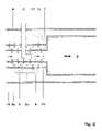
- FIG. 1shows a re-heat combustion system comprising impingement cooling and an acoustic screen applied to the front panel of the burner, in accordance with the invention
- FIG. 2shows a re-heat combustion system with impingement cooling and an acoustic screen applied to the burner mixing tube, in accordance with the invention
- FIG. 3shows a re-heat combustion system with impingement cooling and an acoustic screen applied to the combustion chamber liner, in accordance with the invention
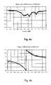
- FIG. 4 ashows the magnitude of the acoustic screen reflection coefficient for a plate with velocity 2.5% and no bias flow velocity through the holes;
- FIG. 4 bshows the phase of the acoustic screen reflection coefficient for a plate with velocity 2.5% and no bias flow velocity through the holes;
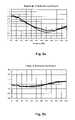
- FIG. 5 ashows the magnitude of the acoustic screen reflection coefficient for a plate with velocity 2.5% and 8 m/s bias flow velocity through the holes.
- FIG. 5 bshows the phase of the acoustic screen reflection coefficient for a plate with velocity 2.5% and 8 m/s bias flow velocity through the holes.
- FIG. 1shows a burner 1 , which is fed with a pre-mixed stream of reactants obtained by mixing the hot oxygen stream (i.e. the products of the primary combustion) entering the burner 1 with fuel injected by lance 2 .
- a pre-mixed stream of reactantsobtained by mixing the hot oxygen stream (i.e. the products of the primary combustion) entering the burner 1 with fuel injected by lance 2 .
- the mixtureenters the combustion chamber 3 , where combustion occurs.
- the walls of the burner 1are perforated and are cooled by air flowing from the plenum 4 .
- the burner mixing tube 15comprises rows of perforations 5 , which admit air flows 5 a . These serve to cool the mixing tube 15 by means of effusion.
- the axially facing front panel 17 of the combustion chamber 3is provided with apertures 7 a which admit an air flow 7 , which cools the front panel 17 by impingement cooling.
- annular screen 16which is parallel to the burner front panel 17 and separated by a short axial distance.
- the mixing tube 15extends into the combustion chamber 3 , so as to terminate at the same axial location as the acoustic screen 16 , thereby providing an annular cavity between the burner front panel 17 and the screen 16 .
- the acoustic screen 16is provided with a further series of apertures 6 and these admit the flow 7 a into the combustion chamber 3 as flow 6 a.
- the annular cavityis configured such that the reactance is 0 or close to 0.
- FIG. 2shows a further embodiment, in which the mixing tube 15 is provided with a cylindrical, co-axial screen 18 , provided with a series of perforations 8 .
- the fluid flow 5 from the plenum 4provides impingement cooling on the mixing tube 15 and, after passing through the cylindrical cavity formed between the screen 18 and the mixing tube 15 , it passes into the core of the mixing tube as flow 8 a via perforations 8 , so as to cause damping of the acoustic waves travelling in the burner 1 .
- the flow 7 through the front panel of the combustion chamber 3is used for effusion cooling.
- FIG. 3shows a further embodiment, in which flows 5 a and 6 a through the mixing tube 15 and burner front panel 16 respectively provide effusion cooling.
- the wall of the combustion chamber 3is perforations by apertures 10 and surrounded by a cylindrical, co-axial jacket 1 a with closed end walls, so as to define a cylindrical cavity around the outside of the wall of the combustion chamber 3 .
- the annular jacket 19is perforated with perforations 9 .
- each of the foregoing embodimentsmight be considered to have the acoustic screen either added to the inside or the outside of the conventional burner 1 , it is, in practice, largely irrelevant which of these is adopted. The significant thing is that there is a dual-layer structure with a cavity in between.
- FIGS. 4 and 5show a comparison between numerical prediction and experimental results for embodiments of perforated screens.
- FIGS. 4 and 5illustrate the reflection coefficient for the same screen, without and with bias flow (and therefore non linear and linear damping) respectively.
- the bias flowbesides allowing the tuning of the resonance frequency, leads to a greater acoustic damping.
- the magnitude plotindicates the maximum absorption for the resonance frequency, which is characterised by a typical phase jump. Both magnitude and phase show a good agreement between prediction and experiment, thereby showing the effectiveness of the embodiments.
Landscapes
- Engineering & Computer Science (AREA)
- Chemical & Material Sciences (AREA)
- Combustion & Propulsion (AREA)
- Mechanical Engineering (AREA)
- General Engineering & Computer Science (AREA)
- Soundproofing, Sound Blocking, And Sound Damping (AREA)
Abstract
Description
- a mixing tube adapted to be fed by products of a primary combustion zone of the gas turbine and by fuel injected by a lance;
- a combustion chamber fed by the said mixing tube; and
- at least one perforated acoustic screen;
- wherein the or each said acoustic screen is provided inside the mixing tube or the said combustion chamber, at a position where it faces, but is spaced from, a perforated wall thereof; such that, in use, the said perforated wall experiences impingement cooling as it admits air into the combustion system for onward passage through the perforations of the said acoustic screen, and the acoustic screen damps acoustic pulsations in the said mixing tube and combustion chamber.
Claims (6)
Applications Claiming Priority (2)
| Application Number | Priority Date | Filing Date | Title |
|---|---|---|---|
| GB0214783AGB2390150A (en) | 2002-06-26 | 2002-06-26 | Reheat combustion system for a gas turbine including an accoustic screen |
| GB0214783.3 | 2002-06-26 |
Publications (2)
| Publication Number | Publication Date |
|---|---|
| US20050229581A1 US20050229581A1 (en) | 2005-10-20 |
| US6981358B2true US6981358B2 (en) | 2006-01-03 |
Family
ID=9939341
Family Applications (1)
| Application Number | Title | Priority Date | Filing Date |
|---|---|---|---|
| US10/460,363Expired - LifetimeUS6981358B2 (en) | 2002-06-26 | 2003-06-13 | Reheat combustion system for a gas turbine |
Country Status (3)
| Country | Link |
|---|---|
| US (1) | US6981358B2 (en) |
| DE (1) | DE10325691A1 (en) |
| GB (1) | GB2390150A (en) |
Cited By (115)
| Publication number | Priority date | Publication date | Assignee | Title |
|---|---|---|---|---|
| US20040088996A1 (en)* | 2000-10-05 | 2004-05-13 | Adnan Eroglu | Method for introducing fuel into a premix burner |
| US20050076648A1 (en)* | 2003-10-10 | 2005-04-14 | Shahram Farhangi | Method and apparatus for injecting a fuel into a combustor assembly |
| US20050097891A1 (en)* | 2003-09-04 | 2005-05-12 | Karl Schreiber | Arrangement for the cooling of thermally highly loaded components |
| US20050106519A1 (en)* | 2002-03-07 | 2005-05-19 | Patrick Flohr | Burner, method for operating a burner and gas turbine |
| US20050144950A1 (en)* | 2002-03-07 | 2005-07-07 | Siemens Aktiengesellschaft | Gas turbine |
| US20050284690A1 (en)* | 2004-06-28 | 2005-12-29 | William Proscia | High admittance acoustic liner |
| US20060010878A1 (en)* | 2004-06-03 | 2006-01-19 | General Electric Company | Method of cooling centerbody of premixing burner |
| US20060053798A1 (en)* | 2004-09-10 | 2006-03-16 | Honeywell International Inc. | Waffled impingement effusion method |
| US20060059916A1 (en)* | 2004-09-09 | 2006-03-23 | Cheung Albert K | Cooled turbine engine components |
| US20060101825A1 (en)* | 2003-03-07 | 2006-05-18 | Valter Bellucci | Premix burner |
| US20060127827A1 (en)* | 2004-10-06 | 2006-06-15 | Shouhei Yoshida | Combustor and combustion method for combustor |
| US20070283700A1 (en)* | 2006-06-09 | 2007-12-13 | Miklos Gerendas | Gas-turbine combustion chamber wall for a lean-burning gas-turbine combustion chamber |
| US20080245337A1 (en)* | 2007-04-03 | 2008-10-09 | Bandaru Ramarao V | System for reducing combustor dynamics |
| US20080276619A1 (en)* | 2007-05-09 | 2008-11-13 | Siemens Power Generation, Inc. | Impingement jets coupled to cooling channels for transition cooling |
| US20080295519A1 (en)* | 2007-05-31 | 2008-12-04 | Roger James Park | Turbine engine fuel injector with Helmholtz resonators |
| US20090277180A1 (en)* | 2008-05-07 | 2009-11-12 | Kam-Kei Lam | Combustor dynamic attenuation and cooling arrangement |
| US20090293490A1 (en)* | 2008-05-28 | 2009-12-03 | Rolls-Royce Plc | Combustor wall with improved cooling |
| US20090301054A1 (en)* | 2008-06-04 | 2009-12-10 | Simpson Stanley F | Turbine system having exhaust gas recirculation and reheat |
| US20100058758A1 (en)* | 2008-09-11 | 2010-03-11 | General Electric Company | Exhaust gas recirculation system, turbomachine system having the exhaust gas recirculation system and exhaust gas recirculation control method |
| US20100077757A1 (en)* | 2008-09-30 | 2010-04-01 | Madhavan Narasimhan Poyyapakkam | Combustor for a gas turbine engine |
| US20100101229A1 (en)* | 2008-10-23 | 2010-04-29 | General Electric Company | Flame Holding Tolerant Fuel and Air Premixer for a Gas Turbine Combustor |
| US20100139281A1 (en)* | 2008-12-10 | 2010-06-10 | Caterpillar Inc. | Fuel injector arrangment having porous premixing chamber |
| US20100293952A1 (en)* | 2009-05-21 | 2010-11-25 | General Electric Company | Resonating Swirler |
| US20110000215A1 (en)* | 2009-07-01 | 2011-01-06 | General Electric Company | Combustor Can Flow Conditioner |
| US20110000671A1 (en)* | 2008-03-28 | 2011-01-06 | Frank Hershkowitz | Low Emission Power Generation and Hydrocarbon Recovery Systems and Methods |
| US20110048018A1 (en)* | 2009-08-31 | 2011-03-03 | Alstom Technology Ltd | Combustion device of a gas turbine |
| US20110139541A1 (en)* | 2008-08-14 | 2011-06-16 | Bruno Schuermans | Method for adjusting a helmholtz resonator and an adjustable helmholtz resonator |
| US20110311924A1 (en)* | 2010-06-22 | 2011-12-22 | Carrier Corporation | Low Pressure Drop, Low NOx, Induced Draft Gas Heaters |
| US20120047908A1 (en)* | 2010-08-27 | 2012-03-01 | Alstom Technology Ltd | Method for operating a burner arrangement and burner arrangement for implementing the method |
| US20120151935A1 (en)* | 2010-12-17 | 2012-06-21 | General Electric Company | Gas turbine engine and method of operating thereof |
| US20120260657A1 (en)* | 2009-09-21 | 2012-10-18 | Alstom Technology Ltd | Combustor of a gas turbine |
| CN102889613A (en)* | 2011-07-22 | 2013-01-23 | 通用电气公司 | System for damping oscillations in a turbine combustor |
| US20130091858A1 (en)* | 2011-10-14 | 2013-04-18 | General Electric Company | Effusion cooled nozzle and related method |
| US8469141B2 (en)* | 2011-08-10 | 2013-06-25 | General Electric Company | Acoustic damping device for use in gas turbine engine |
| US20130247581A1 (en)* | 2012-03-21 | 2013-09-26 | General Electric Company | Systems and Methods for Dampening Combustor Dynamics in a Micromixer |
| US20130255260A1 (en)* | 2012-03-29 | 2013-10-03 | Solar Turbines Inc. | Resonance damper for damping acoustic oscillations from combustor |
| US20130283799A1 (en)* | 2012-04-25 | 2013-10-31 | Solar Turbines Inc. | Resonance damper for damping acoustic oscillations from combustor |
| US20130306181A1 (en)* | 2012-05-17 | 2013-11-21 | Capstone Turbine Corporation | Multistaged Lean Prevaporizing Premixing Fuel Injector |
| US20140033728A1 (en)* | 2011-04-08 | 2014-02-06 | Alstom Technologies Ltd | Gas turbine assembly and corresponding operating method |
| US8647053B2 (en) | 2010-08-09 | 2014-02-11 | Siemens Energy, Inc. | Cooling arrangement for a turbine component |
| US20140116066A1 (en)* | 2012-10-30 | 2014-05-01 | General Electric Company | Combustor cap assembly |
| EP2738469A1 (en) | 2012-11-30 | 2014-06-04 | Alstom Technology Ltd | Gas turbine part comprising a near wall cooling arrangement |
| US20140338332A1 (en)* | 2013-05-14 | 2014-11-20 | Juan Enrique Portillo Bilbao | Acoustic damping system for a combustor of a gas turbine engine |
| US20150000282A1 (en)* | 2012-03-20 | 2015-01-01 | Alstom Technology Ltd | Annular helmholtz damper |
| US8984857B2 (en) | 2008-03-28 | 2015-03-24 | Exxonmobil Upstream Research Company | Low emission power generation and hydrocarbon recovery systems and methods |
| US9027321B2 (en) | 2008-03-28 | 2015-05-12 | Exxonmobil Upstream Research Company | Low emission power generation and hydrocarbon recovery systems and methods |
| US20150159870A1 (en)* | 2010-05-03 | 2015-06-11 | Alstom Technology Ltd | Combustion device for a gas turbine |
| US9222671B2 (en) | 2008-10-14 | 2015-12-29 | Exxonmobil Upstream Research Company | Methods and systems for controlling the products of combustion |
| US9353682B2 (en) | 2012-04-12 | 2016-05-31 | General Electric Company | Methods, systems and apparatus relating to combustion turbine power plants with exhaust gas recirculation |
| US9463417B2 (en) | 2011-03-22 | 2016-10-11 | Exxonmobil Upstream Research Company | Low emission power generation systems and methods incorporating carbon dioxide separation |
| US9512759B2 (en) | 2013-02-06 | 2016-12-06 | General Electric Company | System and method for catalyst heat utilization for gas turbine with exhaust gas recirculation |
| US9574496B2 (en) | 2012-12-28 | 2017-02-21 | General Electric Company | System and method for a turbine combustor |
| US9581081B2 (en) | 2013-01-13 | 2017-02-28 | General Electric Company | System and method for protecting components in a gas turbine engine with exhaust gas recirculation |
| US9587510B2 (en) | 2013-07-30 | 2017-03-07 | General Electric Company | System and method for a gas turbine engine sensor |
| US9599021B2 (en) | 2011-03-22 | 2017-03-21 | Exxonmobil Upstream Research Company | Systems and methods for controlling stoichiometric combustion in low emission turbine systems |
| US9599070B2 (en) | 2012-11-02 | 2017-03-21 | General Electric Company | System and method for oxidant compression in a stoichiometric exhaust gas recirculation gas turbine system |
| US9611756B2 (en) | 2012-11-02 | 2017-04-04 | General Electric Company | System and method for protecting components in a gas turbine engine with exhaust gas recirculation |
| US9618261B2 (en) | 2013-03-08 | 2017-04-11 | Exxonmobil Upstream Research Company | Power generation and LNG production |
| US9617914B2 (en) | 2013-06-28 | 2017-04-11 | General Electric Company | Systems and methods for monitoring gas turbine systems having exhaust gas recirculation |
| US9631815B2 (en) | 2012-12-28 | 2017-04-25 | General Electric Company | System and method for a turbine combustor |
| US9631542B2 (en) | 2013-06-28 | 2017-04-25 | General Electric Company | System and method for exhausting combustion gases from gas turbine engines |
| US9670841B2 (en) | 2011-03-22 | 2017-06-06 | Exxonmobil Upstream Research Company | Methods of varying low emission turbine gas recycle circuits and systems and apparatus related thereto |
| US9689309B2 (en) | 2011-03-22 | 2017-06-27 | Exxonmobil Upstream Research Company | Systems and methods for carbon dioxide capture in low emission combined turbine systems |
| US9708977B2 (en) | 2012-12-28 | 2017-07-18 | General Electric Company | System and method for reheat in gas turbine with exhaust gas recirculation |
| US9732673B2 (en) | 2010-07-02 | 2017-08-15 | Exxonmobil Upstream Research Company | Stoichiometric combustion with exhaust gas recirculation and direct contact cooler |
| US9732675B2 (en) | 2010-07-02 | 2017-08-15 | Exxonmobil Upstream Research Company | Low emission power generation systems and methods |
| US9752458B2 (en) | 2013-12-04 | 2017-09-05 | General Electric Company | System and method for a gas turbine engine |
| US9784140B2 (en) | 2013-03-08 | 2017-10-10 | Exxonmobil Upstream Research Company | Processing exhaust for use in enhanced oil recovery |
| US9784182B2 (en) | 2013-03-08 | 2017-10-10 | Exxonmobil Upstream Research Company | Power generation and methane recovery from methane hydrates |
| US9784185B2 (en) | 2012-04-26 | 2017-10-10 | General Electric Company | System and method for cooling a gas turbine with an exhaust gas provided by the gas turbine |
| US9803865B2 (en) | 2012-12-28 | 2017-10-31 | General Electric Company | System and method for a turbine combustor |
| US9810050B2 (en) | 2011-12-20 | 2017-11-07 | Exxonmobil Upstream Research Company | Enhanced coal-bed methane production |
| US9819292B2 (en) | 2014-12-31 | 2017-11-14 | General Electric Company | Systems and methods to respond to grid overfrequency events for a stoichiometric exhaust recirculation gas turbine |
| US9835089B2 (en) | 2013-06-28 | 2017-12-05 | General Electric Company | System and method for a fuel nozzle |
| US9863267B2 (en) | 2014-01-21 | 2018-01-09 | General Electric Company | System and method of control for a gas turbine engine |
| US9869247B2 (en) | 2014-12-31 | 2018-01-16 | General Electric Company | Systems and methods of estimating a combustion equivalence ratio in a gas turbine with exhaust gas recirculation |
| US9869279B2 (en) | 2012-11-02 | 2018-01-16 | General Electric Company | System and method for a multi-wall turbine combustor |
| US9885290B2 (en) | 2014-06-30 | 2018-02-06 | General Electric Company | Erosion suppression system and method in an exhaust gas recirculation gas turbine system |
| US9903271B2 (en) | 2010-07-02 | 2018-02-27 | Exxonmobil Upstream Research Company | Low emission triple-cycle power generation and CO2 separation systems and methods |
| US9903316B2 (en) | 2010-07-02 | 2018-02-27 | Exxonmobil Upstream Research Company | Stoichiometric combustion of enriched air with exhaust gas recirculation |
| US9903588B2 (en) | 2013-07-30 | 2018-02-27 | General Electric Company | System and method for barrier in passage of combustor of gas turbine engine with exhaust gas recirculation |
| US9915200B2 (en) | 2014-01-21 | 2018-03-13 | General Electric Company | System and method for controlling the combustion process in a gas turbine operating with exhaust gas recirculation |
| US9932874B2 (en) | 2013-02-21 | 2018-04-03 | Exxonmobil Upstream Research Company | Reducing oxygen in a gas turbine exhaust |
| US9938861B2 (en) | 2013-02-21 | 2018-04-10 | Exxonmobil Upstream Research Company | Fuel combusting method |
| US9951658B2 (en) | 2013-07-31 | 2018-04-24 | General Electric Company | System and method for an oxidant heating system |
| US10012151B2 (en) | 2013-06-28 | 2018-07-03 | General Electric Company | Systems and methods for controlling exhaust gas flow in exhaust gas recirculation gas turbine systems |
| US10030588B2 (en) | 2013-12-04 | 2018-07-24 | General Electric Company | Gas turbine combustor diagnostic system and method |
| US10047633B2 (en) | 2014-05-16 | 2018-08-14 | General Electric Company | Bearing housing |
| US10060359B2 (en) | 2014-06-30 | 2018-08-28 | General Electric Company | Method and system for combustion control for gas turbine system with exhaust gas recirculation |
| US10079564B2 (en) | 2014-01-27 | 2018-09-18 | General Electric Company | System and method for a stoichiometric exhaust gas recirculation gas turbine system |
| US10094566B2 (en) | 2015-02-04 | 2018-10-09 | General Electric Company | Systems and methods for high volumetric oxidant flow in gas turbine engine with exhaust gas recirculation |
| US10094570B2 (en) | 2014-12-11 | 2018-10-09 | General Electric Company | Injector apparatus and reheat combustor |
| US10094569B2 (en) | 2014-12-11 | 2018-10-09 | General Electric Company | Injecting apparatus with reheat combustor and turbomachine |
| US10094571B2 (en) | 2014-12-11 | 2018-10-09 | General Electric Company | Injector apparatus with reheat combustor and turbomachine |
| US10100741B2 (en) | 2012-11-02 | 2018-10-16 | General Electric Company | System and method for diffusion combustion with oxidant-diluent mixing in a stoichiometric exhaust gas recirculation gas turbine system |
| US10107498B2 (en) | 2014-12-11 | 2018-10-23 | General Electric Company | Injection systems for fuel and gas |
| US10107495B2 (en) | 2012-11-02 | 2018-10-23 | General Electric Company | Gas turbine combustor control system for stoichiometric combustion in the presence of a diluent |
| US10145269B2 (en) | 2015-03-04 | 2018-12-04 | General Electric Company | System and method for cooling discharge flow |
| US10197275B2 (en) | 2016-05-03 | 2019-02-05 | General Electric Company | High frequency acoustic damper for combustor liners |
| US10208677B2 (en) | 2012-12-31 | 2019-02-19 | General Electric Company | Gas turbine load control system |
| US10215412B2 (en) | 2012-11-02 | 2019-02-26 | General Electric Company | System and method for load control with diffusion combustion in a stoichiometric exhaust gas recirculation gas turbine system |
| US10221762B2 (en) | 2013-02-28 | 2019-03-05 | General Electric Company | System and method for a turbine combustor |
| US10227920B2 (en) | 2014-01-15 | 2019-03-12 | General Electric Company | Gas turbine oxidant separation system |
| US10253690B2 (en) | 2015-02-04 | 2019-04-09 | General Electric Company | Turbine system with exhaust gas recirculation, separation and extraction |
| US10267270B2 (en) | 2015-02-06 | 2019-04-23 | General Electric Company | Systems and methods for carbon black production with a gas turbine engine having exhaust gas recirculation |
| US10273880B2 (en) | 2012-04-26 | 2019-04-30 | General Electric Company | System and method of recirculating exhaust gas for use in a plurality of flow paths in a gas turbine engine |
| US10316746B2 (en) | 2015-02-04 | 2019-06-11 | General Electric Company | Turbine system with exhaust gas recirculation, separation and extraction |
| US10315150B2 (en) | 2013-03-08 | 2019-06-11 | Exxonmobil Upstream Research Company | Carbon dioxide recovery |
| US10480792B2 (en) | 2015-03-06 | 2019-11-19 | General Electric Company | Fuel staging in a gas turbine engine |
| US10655542B2 (en) | 2014-06-30 | 2020-05-19 | General Electric Company | Method and system for startup of gas turbine system drive trains with exhaust gas recirculation |
| US10788212B2 (en) | 2015-01-12 | 2020-09-29 | General Electric Company | System and method for an oxidant passageway in a gas turbine system with exhaust gas recirculation |
| US11156164B2 (en) | 2019-05-21 | 2021-10-26 | General Electric Company | System and method for high frequency accoustic dampers with caps |
| US11174792B2 (en) | 2019-05-21 | 2021-11-16 | General Electric Company | System and method for high frequency acoustic dampers with baffles |
| US20230407819A1 (en)* | 2022-06-17 | 2023-12-21 | Blue Origin, Llc | Multi-volume acoustic resonator for rocket engine |
| US11859539B2 (en) | 2021-02-01 | 2024-01-02 | General Electric Company | Aircraft propulsion system with inter-turbine burner |
Families Citing this family (22)
| Publication number | Priority date | Publication date | Assignee | Title |
|---|---|---|---|---|
| DE502004011481D1 (en)* | 2004-06-07 | 2010-09-16 | Siemens Ag | Combustion chamber with a damping device for damping thermoacoustic oscillations |
| DE102004034138B4 (en)* | 2004-07-15 | 2008-04-03 | Ceramat, S. Coop., Asteasu | Gas-fired heating device |
| GB0425794D0 (en)* | 2004-11-24 | 2004-12-22 | Rolls Royce Plc | Acoustic damper |
| CN101395428B (en)* | 2006-02-28 | 2010-12-08 | 西门子公司 | Gas turbine combustor and method of operating the same |
| EP2362147B1 (en) | 2010-02-22 | 2012-12-26 | Alstom Technology Ltd | Combustion device for a gas turbine |
| RU2531110C2 (en)* | 2010-06-29 | 2014-10-20 | Дженерал Электрик Компани | Gas-turbine unit and unit with injector vanes (versions) |
| EP2587158A1 (en)* | 2011-10-31 | 2013-05-01 | Siemens Aktiengesellschaft | Combustion chamber for a gas turbine and burner assembly |
| WO2013139914A1 (en)* | 2012-03-23 | 2013-09-26 | Alstom Technology Ltd | Combustion device |
| EP2693121B1 (en) | 2012-07-31 | 2018-04-25 | Ansaldo Energia Switzerland AG | Near-wall roughness for damping devices reducing pressure oscillations in combustion systems |
| EP2735796B1 (en) | 2012-11-23 | 2020-01-01 | Ansaldo Energia IP UK Limited | Wall of a hot gas path component of a gas turbine and method for enhancing operational behaviour of a gas turbine |
| EP2762784B1 (en) | 2012-11-30 | 2016-02-03 | Alstom Technology Ltd | Damping device for a gas turbine combustor |
| EP3026346A1 (en)* | 2014-11-25 | 2016-06-01 | Alstom Technology Ltd | Combustor liner |
| EP3051206B1 (en)* | 2015-01-28 | 2019-10-30 | Ansaldo Energia Switzerland AG | Sequential gas turbine combustor arrangement with a mixer and a damper |
| US10844792B2 (en)* | 2015-02-23 | 2020-11-24 | Mitsubishi Heavy Industries Ltd. | Damping device, combustor, and gas turbine |
| US10513984B2 (en) | 2015-08-25 | 2019-12-24 | General Electric Company | System for suppressing acoustic noise within a gas turbine combustor |
| US10145561B2 (en)* | 2016-09-06 | 2018-12-04 | General Electric Company | Fuel nozzle assembly with resonator |
| EP3299721B1 (en)* | 2016-09-22 | 2020-09-02 | Ansaldo Energia Switzerland AG | Annular helmholtz damper for a gas turbine can combustor |
| CN109140501B (en)* | 2017-06-28 | 2021-04-27 | 中国航发贵阳发动机设计研究所 | Double-oil-way double-nozzle centrifugal nozzle structure with double-layer air hood |
| US10941939B2 (en)* | 2017-09-25 | 2021-03-09 | General Electric Company | Gas turbine assemblies and methods |
| US20230194090A1 (en)* | 2021-12-20 | 2023-06-22 | General Electric Company | Combustor with resonator |
| US11788724B1 (en)* | 2022-09-02 | 2023-10-17 | General Electric Company | Acoustic damper for combustor |
| CN117029045A (en)* | 2023-08-18 | 2023-11-10 | 东方电气集团东方汽轮机有限公司 | Structure and method for inhibiting thermoacoustic oscillation of gas turbine combustor |
Citations (11)
| Publication number | Priority date | Publication date | Assignee | Title |
|---|---|---|---|---|
| US3848697A (en) | 1972-07-04 | 1974-11-19 | Aerospatiale | Acoustic damping and cooling of turbojet exhaust ducts |
| US4199936A (en)* | 1975-12-24 | 1980-04-29 | The Boeing Company | Gas turbine engine combustion noise suppressor |
| US5660044A (en)* | 1994-03-04 | 1997-08-26 | Nuovopignone S.P.A. | Perfected combustion system with low polluting emissions for gas turbines |
| US5765376A (en)* | 1994-12-16 | 1998-06-16 | Mtu Motoren- Und Turbinen-Union Muenchen Gmbh | Gas turbine engine flame tube cooling system and integral swirler arrangement |
| US5784876A (en)* | 1995-03-14 | 1998-07-28 | European Gas Turbines Limited | Combuster and operating method for gas-or liquid-fuelled turbine arrangement |
| US5941076A (en)* | 1996-07-25 | 1999-08-24 | Snecma-Societe Nationale D'etude Et De Construction De Moteurs D'aviation | Deflecting feeder bowl assembly for a turbojet engine combustion chamber |
| EP0971172A1 (en) | 1998-07-10 | 2000-01-12 | Asea Brown Boveri AG | Gas turbine combustion chamber with silencing wall structure |
| US6351947B1 (en)* | 2000-04-04 | 2002-03-05 | Abb Alstom Power (Schweiz) | Combustion chamber for a gas turbine |
| US6609376B2 (en)* | 2000-02-14 | 2003-08-26 | Ulstein Turbine As | Device in a burner for gas turbines |
| US6640544B2 (en)* | 2000-12-06 | 2003-11-04 | Mitsubishi Heavy Industries, Ltd. | Gas turbine combustor, gas turbine, and jet engine |
| US6732527B2 (en)* | 2001-05-15 | 2004-05-11 | Rolls-Royce Plc | Combustion chamber |
- 2002
- 2002-06-26GBGB0214783Apatent/GB2390150A/ennot_activeWithdrawn
- 2003
- 2003-06-06DEDE10325691Apatent/DE10325691A1/ennot_activeCeased
- 2003-06-13USUS10/460,363patent/US6981358B2/ennot_activeExpired - Lifetime
Patent Citations (11)
| Publication number | Priority date | Publication date | Assignee | Title |
|---|---|---|---|---|
| US3848697A (en) | 1972-07-04 | 1974-11-19 | Aerospatiale | Acoustic damping and cooling of turbojet exhaust ducts |
| US4199936A (en)* | 1975-12-24 | 1980-04-29 | The Boeing Company | Gas turbine engine combustion noise suppressor |
| US5660044A (en)* | 1994-03-04 | 1997-08-26 | Nuovopignone S.P.A. | Perfected combustion system with low polluting emissions for gas turbines |
| US5765376A (en)* | 1994-12-16 | 1998-06-16 | Mtu Motoren- Und Turbinen-Union Muenchen Gmbh | Gas turbine engine flame tube cooling system and integral swirler arrangement |
| US5784876A (en)* | 1995-03-14 | 1998-07-28 | European Gas Turbines Limited | Combuster and operating method for gas-or liquid-fuelled turbine arrangement |
| US5941076A (en)* | 1996-07-25 | 1999-08-24 | Snecma-Societe Nationale D'etude Et De Construction De Moteurs D'aviation | Deflecting feeder bowl assembly for a turbojet engine combustion chamber |
| EP0971172A1 (en) | 1998-07-10 | 2000-01-12 | Asea Brown Boveri AG | Gas turbine combustion chamber with silencing wall structure |
| US6609376B2 (en)* | 2000-02-14 | 2003-08-26 | Ulstein Turbine As | Device in a burner for gas turbines |
| US6351947B1 (en)* | 2000-04-04 | 2002-03-05 | Abb Alstom Power (Schweiz) | Combustion chamber for a gas turbine |
| US6640544B2 (en)* | 2000-12-06 | 2003-11-04 | Mitsubishi Heavy Industries, Ltd. | Gas turbine combustor, gas turbine, and jet engine |
| US6732527B2 (en)* | 2001-05-15 | 2004-05-11 | Rolls-Royce Plc | Combustion chamber |
Non-Patent Citations (1)
| Title |
|---|
| Search Report in GB 0214783.3 (Aug. 31, 2002). |
Cited By (171)
| Publication number | Priority date | Publication date | Assignee | Title |
|---|---|---|---|---|
| US20040088996A1 (en)* | 2000-10-05 | 2004-05-13 | Adnan Eroglu | Method for introducing fuel into a premix burner |
| US7594402B2 (en) | 2000-10-05 | 2009-09-29 | Alstom Technology Ltd. | Method for the introduction of fuel into a premixing burner |
| US20060277918A1 (en)* | 2000-10-05 | 2006-12-14 | Adnan Eroglu | Method for the introduction of fuel into a premixing burner |
| US7107771B2 (en)* | 2000-10-05 | 2006-09-19 | Alstom Technology Ltd. | Method for introducing fuel into a premix burner |
| US7246493B2 (en)* | 2002-03-07 | 2007-07-24 | Siemens Aktiengesellschaft | Gas turbine |
| US20050144950A1 (en)* | 2002-03-07 | 2005-07-07 | Siemens Aktiengesellschaft | Gas turbine |
| US7320222B2 (en)* | 2002-03-07 | 2008-01-22 | Siemens Aktiengesellschaft | Burner, method for operating a burner and gas turbine |
| US20050106519A1 (en)* | 2002-03-07 | 2005-05-19 | Patrick Flohr | Burner, method for operating a burner and gas turbine |
| US20060101825A1 (en)* | 2003-03-07 | 2006-05-18 | Valter Bellucci | Premix burner |
| US7424804B2 (en)* | 2003-03-07 | 2008-09-16 | Alstom Technology Ltd | Premix burner |
| US20050097891A1 (en)* | 2003-09-04 | 2005-05-12 | Karl Schreiber | Arrangement for the cooling of thermally highly loaded components |
| US7204089B2 (en)* | 2003-09-04 | 2007-04-17 | Rolls-Royce Deutschland Ltd & Co Kg | Arrangement for the cooling of thermally highly loaded components |
| US20050076648A1 (en)* | 2003-10-10 | 2005-04-14 | Shahram Farhangi | Method and apparatus for injecting a fuel into a combustor assembly |
| US7469544B2 (en)* | 2003-10-10 | 2008-12-30 | Pratt & Whitney Rocketdyne | Method and apparatus for injecting a fuel into a combustor assembly |
| US7412833B2 (en)* | 2004-06-03 | 2008-08-19 | General Electric Company | Method of cooling centerbody of premixing burner |
| US20060010878A1 (en)* | 2004-06-03 | 2006-01-19 | General Electric Company | Method of cooling centerbody of premixing burner |
| US7337875B2 (en)* | 2004-06-28 | 2008-03-04 | United Technologies Corporation | High admittance acoustic liner |
| US20050284690A1 (en)* | 2004-06-28 | 2005-12-29 | William Proscia | High admittance acoustic liner |
| US7464554B2 (en)* | 2004-09-09 | 2008-12-16 | United Technologies Corporation | Gas turbine combustor heat shield panel or exhaust panel including a cooling device |
| US20060059916A1 (en)* | 2004-09-09 | 2006-03-23 | Cheung Albert K | Cooled turbine engine components |
| US7219498B2 (en)* | 2004-09-10 | 2007-05-22 | Honeywell International, Inc. | Waffled impingement effusion method |
| US20060053798A1 (en)* | 2004-09-10 | 2006-03-16 | Honeywell International Inc. | Waffled impingement effusion method |
| US20060127827A1 (en)* | 2004-10-06 | 2006-06-15 | Shouhei Yoshida | Combustor and combustion method for combustor |
| US20100170248A1 (en)* | 2004-10-06 | 2010-07-08 | Shouhei Yoshida | Combustor and combustion method for combustor |
| US8596070B2 (en) | 2004-10-06 | 2013-12-03 | Hitachi, Ltd. | Combustor comprising a member including a plurality of air channels and fuel nozzles for supplying fuel into said channels |
| US7610759B2 (en)* | 2004-10-06 | 2009-11-03 | Hitachi, Ltd. | Combustor and combustion method for combustor |
| US7926278B2 (en)* | 2006-06-09 | 2011-04-19 | Rolls-Royce Deutschland Ltd & Co Kg | Gas-turbine combustion chamber wall for a lean-burning gas-turbine combustion chamber |
| US20070283700A1 (en)* | 2006-06-09 | 2007-12-13 | Miklos Gerendas | Gas-turbine combustion chamber wall for a lean-burning gas-turbine combustion chamber |
| US20080245337A1 (en)* | 2007-04-03 | 2008-10-09 | Bandaru Ramarao V | System for reducing combustor dynamics |
| US20080276619A1 (en)* | 2007-05-09 | 2008-11-13 | Siemens Power Generation, Inc. | Impingement jets coupled to cooling channels for transition cooling |
| US7886517B2 (en)* | 2007-05-09 | 2011-02-15 | Siemens Energy, Inc. | Impingement jets coupled to cooling channels for transition cooling |
| US8127546B2 (en)* | 2007-05-31 | 2012-03-06 | Solar Turbines Inc. | Turbine engine fuel injector with helmholtz resonators |
| US20080295519A1 (en)* | 2007-05-31 | 2008-12-04 | Roger James Park | Turbine engine fuel injector with Helmholtz resonators |
| US20110000671A1 (en)* | 2008-03-28 | 2011-01-06 | Frank Hershkowitz | Low Emission Power Generation and Hydrocarbon Recovery Systems and Methods |
| US9027321B2 (en) | 2008-03-28 | 2015-05-12 | Exxonmobil Upstream Research Company | Low emission power generation and hydrocarbon recovery systems and methods |
| US8984857B2 (en) | 2008-03-28 | 2015-03-24 | Exxonmobil Upstream Research Company | Low emission power generation and hydrocarbon recovery systems and methods |
| US8734545B2 (en) | 2008-03-28 | 2014-05-27 | Exxonmobil Upstream Research Company | Low emission power generation and hydrocarbon recovery systems and methods |
| US9121610B2 (en)* | 2008-05-07 | 2015-09-01 | Siemens Aktiengesellschaft | Combustor dynamic attenuation and cooling arrangement |
| US20090277180A1 (en)* | 2008-05-07 | 2009-11-12 | Kam-Kei Lam | Combustor dynamic attenuation and cooling arrangement |
| US20090293490A1 (en)* | 2008-05-28 | 2009-12-03 | Rolls-Royce Plc | Combustor wall with improved cooling |
| US20090301054A1 (en)* | 2008-06-04 | 2009-12-10 | Simpson Stanley F | Turbine system having exhaust gas recirculation and reheat |
| US8205714B2 (en)* | 2008-08-14 | 2012-06-26 | Alstom Technology Ltd. | Method for adjusting a Helmholtz resonator and an adjustable Helmholtz resonator |
| US20110139541A1 (en)* | 2008-08-14 | 2011-06-16 | Bruno Schuermans | Method for adjusting a helmholtz resonator and an adjustable helmholtz resonator |
| US20100058758A1 (en)* | 2008-09-11 | 2010-03-11 | General Electric Company | Exhaust gas recirculation system, turbomachine system having the exhaust gas recirculation system and exhaust gas recirculation control method |
| US9297306B2 (en) | 2008-09-11 | 2016-03-29 | General Electric Company | Exhaust gas recirculation system, turbomachine system having the exhaust gas recirculation system and exhaust gas recirculation control method |
| US8220269B2 (en)* | 2008-09-30 | 2012-07-17 | Alstom Technology Ltd. | Combustor for a gas turbine engine with effusion cooled baffle |
| US20100077757A1 (en)* | 2008-09-30 | 2010-04-01 | Madhavan Narasimhan Poyyapakkam | Combustor for a gas turbine engine |
| US9222671B2 (en) | 2008-10-14 | 2015-12-29 | Exxonmobil Upstream Research Company | Methods and systems for controlling the products of combustion |
| US10495306B2 (en) | 2008-10-14 | 2019-12-03 | Exxonmobil Upstream Research Company | Methods and systems for controlling the products of combustion |
| US9719682B2 (en) | 2008-10-14 | 2017-08-01 | Exxonmobil Upstream Research Company | Methods and systems for controlling the products of combustion |
| US8312722B2 (en)* | 2008-10-23 | 2012-11-20 | General Electric Company | Flame holding tolerant fuel and air premixer for a gas turbine combustor |
| US20100101229A1 (en)* | 2008-10-23 | 2010-04-29 | General Electric Company | Flame Holding Tolerant Fuel and Air Premixer for a Gas Turbine Combustor |
| US20100139281A1 (en)* | 2008-12-10 | 2010-06-10 | Caterpillar Inc. | Fuel injector arrangment having porous premixing chamber |
| US8413446B2 (en) | 2008-12-10 | 2013-04-09 | Caterpillar Inc. | Fuel injector arrangement having porous premixing chamber |
| US20100293952A1 (en)* | 2009-05-21 | 2010-11-25 | General Electric Company | Resonating Swirler |
| US20110000215A1 (en)* | 2009-07-01 | 2011-01-06 | General Electric Company | Combustor Can Flow Conditioner |
| US20110048018A1 (en)* | 2009-08-31 | 2011-03-03 | Alstom Technology Ltd | Combustion device of a gas turbine |
| US8839624B2 (en)* | 2009-08-31 | 2014-09-23 | Alstom Technology Ltd. | Combustion device of a gas turbine including a plurality of passages and chambers defining helmholtz resonators |
| US8635874B2 (en)* | 2009-09-21 | 2014-01-28 | Alstom Technology Ltd | Gas turbine combustor including an acoustic damper device |
| US20120260657A1 (en)* | 2009-09-21 | 2012-10-18 | Alstom Technology Ltd | Combustor of a gas turbine |
| US9857079B2 (en)* | 2010-05-03 | 2018-01-02 | Ansaldo Energia Ip Uk Limited | Combustion device for a gas turbine |
| US20150159870A1 (en)* | 2010-05-03 | 2015-06-11 | Alstom Technology Ltd | Combustion device for a gas turbine |
| US9127837B2 (en)* | 2010-06-22 | 2015-09-08 | Carrier Corporation | Low pressure drop, low NOx, induced draft gas heaters |
| US20110311924A1 (en)* | 2010-06-22 | 2011-12-22 | Carrier Corporation | Low Pressure Drop, Low NOx, Induced Draft Gas Heaters |
| US9903271B2 (en) | 2010-07-02 | 2018-02-27 | Exxonmobil Upstream Research Company | Low emission triple-cycle power generation and CO2 separation systems and methods |
| US9903316B2 (en) | 2010-07-02 | 2018-02-27 | Exxonmobil Upstream Research Company | Stoichiometric combustion of enriched air with exhaust gas recirculation |
| US9732675B2 (en) | 2010-07-02 | 2017-08-15 | Exxonmobil Upstream Research Company | Low emission power generation systems and methods |
| US9732673B2 (en) | 2010-07-02 | 2017-08-15 | Exxonmobil Upstream Research Company | Stoichiometric combustion with exhaust gas recirculation and direct contact cooler |
| US8647053B2 (en) | 2010-08-09 | 2014-02-11 | Siemens Energy, Inc. | Cooling arrangement for a turbine component |
| US9157637B2 (en)* | 2010-08-27 | 2015-10-13 | Alstom Technology Ltd. | Burner arrangement with deflection elements for deflecting cooling air flow |
| US20120047908A1 (en)* | 2010-08-27 | 2012-03-01 | Alstom Technology Ltd | Method for operating a burner arrangement and burner arrangement for implementing the method |
| US20120151935A1 (en)* | 2010-12-17 | 2012-06-21 | General Electric Company | Gas turbine engine and method of operating thereof |
| US9670841B2 (en) | 2011-03-22 | 2017-06-06 | Exxonmobil Upstream Research Company | Methods of varying low emission turbine gas recycle circuits and systems and apparatus related thereto |
| US9689309B2 (en) | 2011-03-22 | 2017-06-27 | Exxonmobil Upstream Research Company | Systems and methods for carbon dioxide capture in low emission combined turbine systems |
| US9599021B2 (en) | 2011-03-22 | 2017-03-21 | Exxonmobil Upstream Research Company | Systems and methods for controlling stoichiometric combustion in low emission turbine systems |
| US9463417B2 (en) | 2011-03-22 | 2016-10-11 | Exxonmobil Upstream Research Company | Low emission power generation systems and methods incorporating carbon dioxide separation |
| US10774740B2 (en)* | 2011-04-08 | 2020-09-15 | Ansaldo Energia Switzerland AG | Gas turbine assembly and corresponding operating method |
| US20140033728A1 (en)* | 2011-04-08 | 2014-02-06 | Alstom Technologies Ltd | Gas turbine assembly and corresponding operating method |
| US9341375B2 (en)* | 2011-07-22 | 2016-05-17 | General Electric Company | System for damping oscillations in a turbine combustor |
| CN102889613B (en)* | 2011-07-22 | 2016-12-21 | 通用电气公司 | For the system that the vibration in turbomachine combustor is damped |
| EP2549189A3 (en)* | 2011-07-22 | 2015-05-13 | General Electric Company | System for damping oscillations in a turbine combustor |
| CN102889613A (en)* | 2011-07-22 | 2013-01-23 | 通用电气公司 | System for damping oscillations in a turbine combustor |
| US20130019602A1 (en)* | 2011-07-22 | 2013-01-24 | General Electric Company | System for damping oscillations in a turbine combustor |
| US8469141B2 (en)* | 2011-08-10 | 2013-06-25 | General Electric Company | Acoustic damping device for use in gas turbine engine |
| US20130091858A1 (en)* | 2011-10-14 | 2013-04-18 | General Electric Company | Effusion cooled nozzle and related method |
| US9810050B2 (en) | 2011-12-20 | 2017-11-07 | Exxonmobil Upstream Research Company | Enhanced coal-bed methane production |
| US20150000282A1 (en)* | 2012-03-20 | 2015-01-01 | Alstom Technology Ltd | Annular helmholtz damper |
| US9618206B2 (en)* | 2012-03-20 | 2017-04-11 | General Electric Technology Gmbh | Annular helmholtz damper |
| US20130247581A1 (en)* | 2012-03-21 | 2013-09-26 | General Electric Company | Systems and Methods for Dampening Combustor Dynamics in a Micromixer |
| US9188342B2 (en)* | 2012-03-21 | 2015-11-17 | General Electric Company | Systems and methods for dampening combustor dynamics in a micromixer |
| US20130255260A1 (en)* | 2012-03-29 | 2013-10-03 | Solar Turbines Inc. | Resonance damper for damping acoustic oscillations from combustor |
| US9353682B2 (en) | 2012-04-12 | 2016-05-31 | General Electric Company | Methods, systems and apparatus relating to combustion turbine power plants with exhaust gas recirculation |
| US20130283799A1 (en)* | 2012-04-25 | 2013-10-31 | Solar Turbines Inc. | Resonance damper for damping acoustic oscillations from combustor |
| US9784185B2 (en) | 2012-04-26 | 2017-10-10 | General Electric Company | System and method for cooling a gas turbine with an exhaust gas provided by the gas turbine |
| US10273880B2 (en) | 2012-04-26 | 2019-04-30 | General Electric Company | System and method of recirculating exhaust gas for use in a plurality of flow paths in a gas turbine engine |
| US9366432B2 (en)* | 2012-05-17 | 2016-06-14 | Capstone Turbine Corporation | Multistaged lean prevaporizing premixing fuel injector |
| US20130306181A1 (en)* | 2012-05-17 | 2013-11-21 | Capstone Turbine Corporation | Multistaged Lean Prevaporizing Premixing Fuel Injector |
| US10197282B2 (en) | 2012-05-17 | 2019-02-05 | Capstone Turbine Corporation | Multistaged lean prevaporizing premixing fuel injector |
| US20140116066A1 (en)* | 2012-10-30 | 2014-05-01 | General Electric Company | Combustor cap assembly |
| US8756934B2 (en)* | 2012-10-30 | 2014-06-24 | General Electric Company | Combustor cap assembly |
| US10107495B2 (en) | 2012-11-02 | 2018-10-23 | General Electric Company | Gas turbine combustor control system for stoichiometric combustion in the presence of a diluent |
| US10215412B2 (en) | 2012-11-02 | 2019-02-26 | General Electric Company | System and method for load control with diffusion combustion in a stoichiometric exhaust gas recirculation gas turbine system |
| US9599070B2 (en) | 2012-11-02 | 2017-03-21 | General Electric Company | System and method for oxidant compression in a stoichiometric exhaust gas recirculation gas turbine system |
| US9611756B2 (en) | 2012-11-02 | 2017-04-04 | General Electric Company | System and method for protecting components in a gas turbine engine with exhaust gas recirculation |
| US9869279B2 (en) | 2012-11-02 | 2018-01-16 | General Electric Company | System and method for a multi-wall turbine combustor |
| US10161312B2 (en) | 2012-11-02 | 2018-12-25 | General Electric Company | System and method for diffusion combustion with fuel-diluent mixing in a stoichiometric exhaust gas recirculation gas turbine system |
| US10138815B2 (en) | 2012-11-02 | 2018-11-27 | General Electric Company | System and method for diffusion combustion in a stoichiometric exhaust gas recirculation gas turbine system |
| US10100741B2 (en) | 2012-11-02 | 2018-10-16 | General Electric Company | System and method for diffusion combustion with oxidant-diluent mixing in a stoichiometric exhaust gas recirculation gas turbine system |
| US10683801B2 (en) | 2012-11-02 | 2020-06-16 | General Electric Company | System and method for oxidant compression in a stoichiometric exhaust gas recirculation gas turbine system |
| EP2738469A1 (en) | 2012-11-30 | 2014-06-04 | Alstom Technology Ltd | Gas turbine part comprising a near wall cooling arrangement |
| US9945561B2 (en) | 2012-11-30 | 2018-04-17 | Ansaldo Energia Ip Uk Limited | Gas turbine part comprising a near wall cooling arrangement |
| US9803865B2 (en) | 2012-12-28 | 2017-10-31 | General Electric Company | System and method for a turbine combustor |
| US9708977B2 (en) | 2012-12-28 | 2017-07-18 | General Electric Company | System and method for reheat in gas turbine with exhaust gas recirculation |
| US9574496B2 (en) | 2012-12-28 | 2017-02-21 | General Electric Company | System and method for a turbine combustor |
| US9631815B2 (en) | 2012-12-28 | 2017-04-25 | General Electric Company | System and method for a turbine combustor |
| US10208677B2 (en) | 2012-12-31 | 2019-02-19 | General Electric Company | Gas turbine load control system |
| US9581081B2 (en) | 2013-01-13 | 2017-02-28 | General Electric Company | System and method for protecting components in a gas turbine engine with exhaust gas recirculation |
| US9512759B2 (en) | 2013-02-06 | 2016-12-06 | General Electric Company | System and method for catalyst heat utilization for gas turbine with exhaust gas recirculation |
| US9938861B2 (en) | 2013-02-21 | 2018-04-10 | Exxonmobil Upstream Research Company | Fuel combusting method |
| US10082063B2 (en) | 2013-02-21 | 2018-09-25 | Exxonmobil Upstream Research Company | Reducing oxygen in a gas turbine exhaust |
| US9932874B2 (en) | 2013-02-21 | 2018-04-03 | Exxonmobil Upstream Research Company | Reducing oxygen in a gas turbine exhaust |
| US10221762B2 (en) | 2013-02-28 | 2019-03-05 | General Electric Company | System and method for a turbine combustor |
| US10315150B2 (en) | 2013-03-08 | 2019-06-11 | Exxonmobil Upstream Research Company | Carbon dioxide recovery |
| US9618261B2 (en) | 2013-03-08 | 2017-04-11 | Exxonmobil Upstream Research Company | Power generation and LNG production |
| US9784140B2 (en) | 2013-03-08 | 2017-10-10 | Exxonmobil Upstream Research Company | Processing exhaust for use in enhanced oil recovery |
| US9784182B2 (en) | 2013-03-08 | 2017-10-10 | Exxonmobil Upstream Research Company | Power generation and methane recovery from methane hydrates |
| US9400108B2 (en)* | 2013-05-14 | 2016-07-26 | Siemens Aktiengesellschaft | Acoustic damping system for a combustor of a gas turbine engine |
| US20140338332A1 (en)* | 2013-05-14 | 2014-11-20 | Juan Enrique Portillo Bilbao | Acoustic damping system for a combustor of a gas turbine engine |
| US9617914B2 (en) | 2013-06-28 | 2017-04-11 | General Electric Company | Systems and methods for monitoring gas turbine systems having exhaust gas recirculation |
| US10012151B2 (en) | 2013-06-28 | 2018-07-03 | General Electric Company | Systems and methods for controlling exhaust gas flow in exhaust gas recirculation gas turbine systems |
| US9631542B2 (en) | 2013-06-28 | 2017-04-25 | General Electric Company | System and method for exhausting combustion gases from gas turbine engines |
| US9835089B2 (en) | 2013-06-28 | 2017-12-05 | General Electric Company | System and method for a fuel nozzle |
| US9903588B2 (en) | 2013-07-30 | 2018-02-27 | General Electric Company | System and method for barrier in passage of combustor of gas turbine engine with exhaust gas recirculation |
| US9587510B2 (en) | 2013-07-30 | 2017-03-07 | General Electric Company | System and method for a gas turbine engine sensor |
| US9951658B2 (en) | 2013-07-31 | 2018-04-24 | General Electric Company | System and method for an oxidant heating system |
| US10731512B2 (en) | 2013-12-04 | 2020-08-04 | Exxonmobil Upstream Research Company | System and method for a gas turbine engine |
| US9752458B2 (en) | 2013-12-04 | 2017-09-05 | General Electric Company | System and method for a gas turbine engine |
| US10030588B2 (en) | 2013-12-04 | 2018-07-24 | General Electric Company | Gas turbine combustor diagnostic system and method |
| US10900420B2 (en) | 2013-12-04 | 2021-01-26 | Exxonmobil Upstream Research Company | Gas turbine combustor diagnostic system and method |
| US10227920B2 (en) | 2014-01-15 | 2019-03-12 | General Electric Company | Gas turbine oxidant separation system |
| US9863267B2 (en) | 2014-01-21 | 2018-01-09 | General Electric Company | System and method of control for a gas turbine engine |
| US9915200B2 (en) | 2014-01-21 | 2018-03-13 | General Electric Company | System and method for controlling the combustion process in a gas turbine operating with exhaust gas recirculation |
| US10727768B2 (en) | 2014-01-27 | 2020-07-28 | Exxonmobil Upstream Research Company | System and method for a stoichiometric exhaust gas recirculation gas turbine system |
| US10079564B2 (en) | 2014-01-27 | 2018-09-18 | General Electric Company | System and method for a stoichiometric exhaust gas recirculation gas turbine system |
| US10047633B2 (en) | 2014-05-16 | 2018-08-14 | General Electric Company | Bearing housing |
| US10060359B2 (en) | 2014-06-30 | 2018-08-28 | General Electric Company | Method and system for combustion control for gas turbine system with exhaust gas recirculation |
| US10655542B2 (en) | 2014-06-30 | 2020-05-19 | General Electric Company | Method and system for startup of gas turbine system drive trains with exhaust gas recirculation |
| US10738711B2 (en) | 2014-06-30 | 2020-08-11 | Exxonmobil Upstream Research Company | Erosion suppression system and method in an exhaust gas recirculation gas turbine system |
| US9885290B2 (en) | 2014-06-30 | 2018-02-06 | General Electric Company | Erosion suppression system and method in an exhaust gas recirculation gas turbine system |
| US10094570B2 (en) | 2014-12-11 | 2018-10-09 | General Electric Company | Injector apparatus and reheat combustor |
| US10107498B2 (en) | 2014-12-11 | 2018-10-23 | General Electric Company | Injection systems for fuel and gas |
| US10094571B2 (en) | 2014-12-11 | 2018-10-09 | General Electric Company | Injector apparatus with reheat combustor and turbomachine |
| US10094569B2 (en) | 2014-12-11 | 2018-10-09 | General Electric Company | Injecting apparatus with reheat combustor and turbomachine |
| US9869247B2 (en) | 2014-12-31 | 2018-01-16 | General Electric Company | Systems and methods of estimating a combustion equivalence ratio in a gas turbine with exhaust gas recirculation |
| US9819292B2 (en) | 2014-12-31 | 2017-11-14 | General Electric Company | Systems and methods to respond to grid overfrequency events for a stoichiometric exhaust recirculation gas turbine |
| US10788212B2 (en) | 2015-01-12 | 2020-09-29 | General Electric Company | System and method for an oxidant passageway in a gas turbine system with exhaust gas recirculation |
| US10316746B2 (en) | 2015-02-04 | 2019-06-11 | General Electric Company | Turbine system with exhaust gas recirculation, separation and extraction |
| US10253690B2 (en) | 2015-02-04 | 2019-04-09 | General Electric Company | Turbine system with exhaust gas recirculation, separation and extraction |
| US10094566B2 (en) | 2015-02-04 | 2018-10-09 | General Electric Company | Systems and methods for high volumetric oxidant flow in gas turbine engine with exhaust gas recirculation |
| US10267270B2 (en) | 2015-02-06 | 2019-04-23 | General Electric Company | Systems and methods for carbon black production with a gas turbine engine having exhaust gas recirculation |
| US10145269B2 (en) | 2015-03-04 | 2018-12-04 | General Electric Company | System and method for cooling discharge flow |
| US10968781B2 (en) | 2015-03-04 | 2021-04-06 | General Electric Company | System and method for cooling discharge flow |
| US10480792B2 (en) | 2015-03-06 | 2019-11-19 | General Electric Company | Fuel staging in a gas turbine engine |
| US10197275B2 (en) | 2016-05-03 | 2019-02-05 | General Electric Company | High frequency acoustic damper for combustor liners |
| US11156164B2 (en) | 2019-05-21 | 2021-10-26 | General Electric Company | System and method for high frequency accoustic dampers with caps |
| US11174792B2 (en) | 2019-05-21 | 2021-11-16 | General Electric Company | System and method for high frequency acoustic dampers with baffles |
| US11859539B2 (en) | 2021-02-01 | 2024-01-02 | General Electric Company | Aircraft propulsion system with inter-turbine burner |
| US20230407819A1 (en)* | 2022-06-17 | 2023-12-21 | Blue Origin, Llc | Multi-volume acoustic resonator for rocket engine |
| US11867139B1 (en)* | 2022-06-17 | 2024-01-09 | Blue Origin, Llc | Multi-volume acoustic resonator for rocket engine |
| US20240191676A1 (en)* | 2022-06-17 | 2024-06-13 | Blue Origin, Llc | Multi-volume acoustic resonator for rocket engine |
| US12146454B2 (en)* | 2022-06-17 | 2024-11-19 | Blue Origin, Llc | Multi-volume acoustic resonator for rocket engine |
Also Published As
| Publication number | Publication date |
|---|---|
| DE10325691A1 (en) | 2004-01-22 |
| GB2390150A (en) | 2003-12-31 |
| GB0214783D0 (en) | 2002-08-07 |
| US20050229581A1 (en) | 2005-10-20 |
Similar Documents
| Publication | Publication Date | Title |
|---|---|---|
| US6981358B2 (en) | Reheat combustion system for a gas turbine | |
| JP6059902B2 (en) | Sound damping device used in gas turbine engine | |
| US7549290B2 (en) | Acoustic damper | |
| US6351947B1 (en) | Combustion chamber for a gas turbine | |
| CA2587058C (en) | Noise reducing combustor | |
| US7334408B2 (en) | Combustion chamber for a gas turbine with at least two resonator devices | |
| US8839624B2 (en) | Combustion device of a gas turbine including a plurality of passages and chambers defining helmholtz resonators | |
| US7784283B2 (en) | Sound-absorbing exhaust nozzle center plug | |
| EP1221574B2 (en) | Gas turbine combustor | |
| US4199936A (en) | Gas turbine engine combustion noise suppressor | |
| EP2549189B1 (en) | System for damping oscillations in a turbine combustor | |
| EP1612769B1 (en) | High admittance acoustic liner | |
| US11136942B2 (en) | Acoustic deep cavity centerbody | |
| EP0635632A1 (en) | Fixed geometry mixer/ejector noise suppression system for turbofan aircraft engines | |
| US8485309B2 (en) | Apparatus and method for improving the damping of acoustic waves | |
| JP2016525207A (en) | Cooling cover for gas turbine damped resonator | |
| US6164058A (en) | Arrangement for damping combustion-chamber oscillations | |
| JP2006524791A (en) | Noise suppression combustor | |
| US10197275B2 (en) | High frequency acoustic damper for combustor liners | |
| US7065971B2 (en) | Device for efficient usage of cooling air for acoustic damping of combustion chamber pulsations | |
| EP1557609A1 (en) | Device and method for damping thermoacoustic oscillations in a combustion chamber | |
| Zhang et al. | Experimental and Analytical Study on Suppressing Combustion Oscillations with Acoustic Metamaterial Burner |
Legal Events
| Date | Code | Title | Description |
|---|---|---|---|
| AS | Assignment | Owner name:ALSTOM (SWITZERLAND) LTD., SWITZERLAND Free format text:ASSIGNMENT OF ASSIGNORS INTEREST;ASSIGNORS:BELLUCCI, VALTER;FLOHR, PETER;PASCHEREIT, CHRISTIAN OLIVER;AND OTHERS;REEL/FRAME:014155/0103;SIGNING DATES FROM 20030603 TO 20030716 | |
| AS | Assignment | Owner name:ALSTOM TECHNOLOGY LTD., SWITZERLAND Free format text:ASSIGNMENT OF ASSIGNORS INTEREST;ASSIGNOR:ALSTOM (SWITZERLAND) LTD.;REEL/FRAME:014247/0585 Effective date:20031114 Owner name:ALSTOM TECHNOLOGY LTD.,SWITZERLAND Free format text:ASSIGNMENT OF ASSIGNORS INTEREST;ASSIGNOR:ALSTOM (SWITZERLAND) LTD.;REEL/FRAME:014247/0585 Effective date:20031114 | |
| STCF | Information on status: patent grant | Free format text:PATENTED CASE | |
| FEPP | Fee payment procedure | Free format text:PAYOR NUMBER ASSIGNED (ORIGINAL EVENT CODE: ASPN); ENTITY STATUS OF PATENT OWNER: LARGE ENTITY | |
| FPAY | Fee payment | Year of fee payment:4 | |
| FPAY | Fee payment | Year of fee payment:8 | |
| AS | Assignment | Owner name:GENERAL ELECTRIC TECHNOLOGY GMBH, SWITZERLAND Free format text:CHANGE OF NAME;ASSIGNOR:ALSTOM TECHNOLOGY LTD;REEL/FRAME:038216/0193 Effective date:20151102 | |
| AS | Assignment | Owner name:ANSALDO ENERGIA IP UK LIMITED, GREAT BRITAIN Free format text:ASSIGNMENT OF ASSIGNORS INTEREST;ASSIGNOR:GENERAL ELECTRIC TECHNOLOGY GMBH;REEL/FRAME:041731/0626 Effective date:20170109 | |
| FPAY | Fee payment | Year of fee payment:12 |