US6980848B2 - Optical MRI catheter system - Google Patents
Optical MRI catheter systemDownload PDFInfo
- Publication number
- US6980848B2 US6980848B2US11/119,718US11971805AUS6980848B2US 6980848 B2US6980848 B2US 6980848B2US 11971805 AUS11971805 AUS 11971805AUS 6980848 B2US6980848 B2US 6980848B2
- Authority
- US
- United States
- Prior art keywords
- optical
- assembly
- catheter
- signals
- electrical
- Prior art date
- Legal status (The legal status is an assumption and is not a legal conclusion. Google has not performed a legal analysis and makes no representation as to the accuracy of the status listed.)
- Expired - Fee Related
Links
Images


Classifications
- A—HUMAN NECESSITIES
- A61—MEDICAL OR VETERINARY SCIENCE; HYGIENE
- A61B—DIAGNOSIS; SURGERY; IDENTIFICATION
- A61B5/00—Measuring for diagnostic purposes; Identification of persons
- A61B5/05—Detecting, measuring or recording for diagnosis by means of electric currents or magnetic fields; Measuring using microwaves or radio waves
- A61B5/055—Detecting, measuring or recording for diagnosis by means of electric currents or magnetic fields; Measuring using microwaves or radio waves involving electronic [EMR] or nuclear [NMR] magnetic resonance, e.g. magnetic resonance imaging
- G—PHYSICS
- G01—MEASURING; TESTING
- G01R—MEASURING ELECTRIC VARIABLES; MEASURING MAGNETIC VARIABLES
- G01R33/00—Arrangements or instruments for measuring magnetic variables
- G01R33/20—Arrangements or instruments for measuring magnetic variables involving magnetic resonance
- G01R33/28—Details of apparatus provided for in groups G01R33/44 - G01R33/64
- G01R33/285—Invasive instruments, e.g. catheters or biopsy needles, specially adapted for tracking, guiding or visualization by NMR
- G—PHYSICS
- G01—MEASURING; TESTING
- G01R—MEASURING ELECTRIC VARIABLES; MEASURING MAGNETIC VARIABLES
- G01R33/00—Arrangements or instruments for measuring magnetic variables
- G01R33/20—Arrangements or instruments for measuring magnetic variables involving magnetic resonance
- G01R33/28—Details of apparatus provided for in groups G01R33/44 - G01R33/64
- G01R33/32—Excitation or detection systems, e.g. using radio frequency signals
- G01R33/34—Constructional details, e.g. resonators, specially adapted to MR
- G01R33/34084—Constructional details, e.g. resonators, specially adapted to MR implantable coils or coils being geometrically adaptable to the sample, e.g. flexible coils or coils comprising mutually movable parts
- G—PHYSICS
- G01—MEASURING; TESTING
- G01R—MEASURING ELECTRIC VARIABLES; MEASURING MAGNETIC VARIABLES
- G01R33/00—Arrangements or instruments for measuring magnetic variables
- G01R33/20—Arrangements or instruments for measuring magnetic variables involving magnetic resonance
- G01R33/28—Details of apparatus provided for in groups G01R33/44 - G01R33/64
- G01R33/32—Excitation or detection systems, e.g. using radio frequency signals
- G01R33/36—Electrical details, e.g. matching or coupling of the coil to the receiver
- G01R33/3692—Electrical details, e.g. matching or coupling of the coil to the receiver involving signal transmission without using electrically conductive connections, e.g. wireless communication or optical communication of the MR signal or an auxiliary signal other than the MR signal
Definitions
- An invasive apparatusfor receiving a magnetic resonance signal from within a body and providing means for transmitting the signal to the received signal input channel of standard magnetic resonance systems.
- Magnetic resonance imaging(“MRI”) has been developed as an imaging technique adapted to obtain both images of anatomical features of human patients as well as some aspects of the functional activities and characteristics of biological tissue. These images and/or functional and/or chemical measurements have medical diagnostic value in determining the state of the health of the tissue examined.
- a patientis typically aligned to place the portion of the patient's anatomy to be examined in the imaging volume of the MRI apparatus.
- Such an MRI apparatustypically comprises a primary magnet for supplying a constant magnetic field (B 0 ) which, by convention, is along the z-axis and is substantially homogeneous over the imaging volume and secondary magnets that can provide linear magnetic field gradients along each of three principal Cartesian axes in space (generally x, y, and z, or x 1 , x 2 and x 3 , respectively).
- a magnetic field gradient( ⁇ B 0 / ⁇ x i ) refers to the variation of the field along the direction parallel to B 0 with respect to each of the three principal Cartesian axes, x i .
- the apparatusalso comprises one or more RF (radio frequency) coils which provide excitation and detection of the MRI signal. Additionally or alternatively, detection coils may be designed into the distal end of a catheter to be inserted into a patient. When such catheters are employed, their proximal ends are connected to the signal input channel of the magnetic resonance imaging device. The detected signal is transmitted along the length of the catheter from the receiving antenna and/or receiving coil in the distal end to the MRI input channel connected at the proximal end.
- the coil or antennacan be placed closer to the tissue which is to be imaged or analyzed.
- the detected signalis less susceptible to radio frequency noise.
- the level of detail that can be resolvedis increased by the use of catheter coils.
- an apparatussuch as a catheter which can be used with a magnetic resonance system for insertion and positioning of an magnetic resonance receiver coil or antenna within a body which is not susceptible to the heating, noise pickup, electrostatic buildup and/or other hazards associated with the use of conductors in a magnetic resonance environment.
- an assembly for delivering optical signalscomprising a nuclear magnetic resonance system; an optical interface assembly electrically connected to the nuclear magnetic resonance system, the optical interface assembly comprising a first laser for producing laser optical signals, an interface optical to electrical signal convertor, and an interface optical connector assembly; and a catheter assembly comprising a proximal end, a distal end, and a catheter optical connector assembly disposed at the proximal end and connected to the interface optical connector assembly of the optical interface assembly, a fiber optic cable assembly, an electronics assembly disposed at the distal end comprised of a catheter electrical to optical signal convertor and a catheter optical to electrical signal convertor, and a first receiving coil disposed at the distal end.
- the laser optical signals received through the fiber optic cable assembly from the first laserare converted into catheter electrical signals by the catheter optical to electrical signal convertor; and the first receiving coil is adapted to receive electromagnetic signals and deliver coil electrical signals to the electronics assembly of the catheter assembly.
- the coil electrical signalsare converted by the catheter electrical to optical signal convertor to catheter optical signals and the catheter optical signals are delivered through the fiber optic cable assembly to the interface optical to electrical signal convertor; and the catheter optical signals are converted by the interface optical to electrical signal convertor into interface electrical signals and are delivered to the nuclear magnetic resonance system.
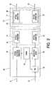
- FIG. 1is a block diagram of one preferred apparatus of the invention
- FIG. 2is a block diagram of the Optical Interface component of the device of FIG. 1 ;
- FIG. 3is a block diagram of another Optical Interface component
- FIGS. 4 through 7are component diagrams of the distal end of the catheter used in the device of FIG. 1 ;
- FIG. 8Ais a block diagram of another design of the distal end of the catheter used in the device of FIG. 1 ;
- FIG. 8Bis a schematic of the electronic components of the distal end.
- FIG. 8Cis a block diagram of the Optical Interface wherein the catheter comprises a single optic strand.
- the apparatus of this patent applicationcomprises the structure shown in FIG. 1 .
- a standard magnetic resonance system 10e.g. the GE Signa Infinity 1.5Tesla system, or Siemens Symphony 1.5 Tesla system
- means for generating and controlling magnetic fields 18which may comprise electromagnets and/or permanent magnets
- a programmable logic unit 20e.g. the GE Signa Infinity 1.5Tesla system, or Siemens Symphony 1.5 Tesla system
- the receiver input channel 22is used to pass the detected signals to the programmable logic unit for image reconstruction.
- the command/gating output channel 32is used to provide at minimum gating signals synchronized to the application of the gradient magnetic fields of the magnetic resonance system 10 .
- an optical interface assembly 34is connected to the receiver input channel 22 and to the command/gating output channel 32 of the magnetic resonance system 10 .
- the optical interface assembly 34converts the electrical command/gating signals of the magnetic resonance system 10 issued through the command/gating output channel 32 into optical signals and transmits these optical signals through the catheter assembly 12 .
- the optical interface assembly 34also converts the optical signals received from the catheter 12 into electrical signals suitable for the magnetic resonance system's 10 receiver input channel 22 .
- the optical interface assembly 34is connected to the catheter assembly 12 through optical connector assembly 36 within the optical interface assembly 34 and optical connector assembly 24 in the proximal end 14 of the catheter assembly 12 .
- Optical connectorsare well known to those skilled in the arts. Reference may be had, e.g., to U.S. Pat. No. 6,149,313 (Gender selectable fiber optic connector and associated fabrication method), which discloses “A gender selectable fiber optic connector is provided which can be readily converted between male and female configurations following assembly and polishing of the connector.” U.S. Pat. No.
- Optical connectordiscloses “A novel optical connector that includes the following: an optical connector ferrule which is capable of fixing optical fibers; optical fibers fixed onto the optical connector ferrule, such that the end surfaces of the optical fibers project beyond an end surface of the optical connector ferrule; an adhesive for fixing the optical fibers onto the optical connector ferrule; and a member whose Young's Modulus is less than that of the optical fiber and is provided to an area on the end surface of the optical connector ferrule surrounding, at a minimum, the projected portions of the optical fibers.” Further reference may be had to U.S. Pat. No. 4,934,785 (Optical fiber connector), U.S. Pat. No. 5,963,690 (Optical fiber connector), U.S. Pat.
- the optical connector assemblies 36 , 24may be so constructed as to allow the catheter assembly 12 to be detached from the optical interface assembly 34 .
- the interconnectincludes a multiple optical fiber connector and an optoelectronic board.
- the multiple fiber connectorcan be mechanically attached to or detached from the board.”
- the optical connectors 24are fabricated to one end of the fiber optic cable assembly 26 .
- the fiber optical cable assembly 26may comprise one or more fiber optical strands suitable for transmitting optical signals from the distal end 16 of the catheter assembly 12 to the proximal end 14 of the catheter assembly 12 .
- Such fiber optic cable assembly 26is typical of prior art optical cable assemblies. Reference may be had, e.g., to U.S. Pat. No. 4,784,461 (optical cable with improved strength), U.S. Pat. No. 6,259,843 (optical cable), U.S. Pat. No. 5,611,016 (dispersion balanced optical cable), U.S. Pat. No. 4,911,525 (optical communications cable), U.S. Pat. No. 4,798,443 (optical cable), U.S. Pat. No. 5,634,720 (multi-purpose multi-parameter cardiac catheter), and the like. The entire disclosure of each of these United States patents is hereby incorporated by reference into this specification.
- fiber optic cable assembly 26may comprise one or more lumens (not shown) suitable for the transport of a gas, e.g., air, or a liquid, e.g., a soluble drug in a saline or other solution, through the length of the catheter assembly 12 .
- a gase.g., air
- a liquide.g., a soluble drug in a saline or other solution
- said lumensmay allow a flexible solid material, e.g. a flexible plastic rod, to be maneuvered through the length of the catheter assembly 12 .
- Such lumens (not shown)are well known to those skilled in the arts of catheter assemblies and are typically used to extend or retract position stabilizing balloons (not shown) or other position stabilizing means built into the catheter assembly 12 .
- said lumensare used for performing biopsies, delivering stents, delivering drugs, and/or for other therapeutic purpose and/or medical procedures.
- Such lumensmay be made from nonconductive, nonmagnetic material, e.g. plastics, or silicon dioxide, etc.
- Reference to such catheter assembliesmay be made to International patent publication PCT WO 01/74241 A2 (Systems And Methods For Evaluating The Urethra And The Periurethral Tissues), U.S. Pat. No. 6,056,721 (Balloon catheter and method), U.S. Pat. No. 5,575,772 (Albation catheters), U.S. Pat. No. 6,146,415 (Stent delivery system), and the like. The entire disclosure of each of these United States patents is hereby incorporated by reference into this specification.
- the fiber optic cable assembly 26is connected to an electronic assembly 28 within the distal end 16 of the catheter assembly 12 .
- the electronic assembly 28provides the means for converting the electrical signal received by the pickup coil(s) 30 into an optical signal and to transmit said optical signal through the fiber optic cable assembly 26 to the proximal end 14 of the catheter assembly 12 .
- electronic assembly 28may receive optically encoded command/gating signals which originate as electrical signals from the magnetic resonance system's 10 command/gating output channel 32 , which are converted to optical command/gating signals in the optical interface 34 . Said command/gating signals may be used by the electronic assembly 28 to, e.g.
- said optical command/gating signalsmay be converted in total or in part into electrical power in the electronic assembly 28 .
- the receiving catheter coils 30may be any one of or a multiplicity of several coils and/or antenna used to receive signals from the tissues that have been excited by the magnetic resonance system 10 .
- Various catheter coil designsare well known to those skilled in the arts. Reference may be had to, e.g., U.S. Pat. No.
- 5,699,801(Method of internal magnetic resonance imaging and spectroscopic analysis and associated apparatus) discloses “The invention provides a method for magnetic resonance imaging and spectroscopic analysis of the interior of a specimen which includes positioning the specimen within a main magnetic field, introducing an invasive probe having an elongated receiver coil into or adjacent to the specimen with the coil having at least one pair of elongated electrical conductors, preferably, generally parallel to each other disposed within a dielectric material and having a pair of ends electrically connected to each other.
- RF pulsesare provided to the region of interest to excite magnetic resonance signals
- gradient magnetic pulsesare applied to the region of interest with the receiver coil receiving magnetic resonance signals and emitting responsive output signals which may be processed by a computer to provide image information for display in a desired manner.
- FIG. 2is a schematic of an optical interface assembly 34 that may be used in the device of FIG. 1 .
- optical connectors 54 and 62 of the optical interface assembly 34are the mating connectors to connectors 68 and 70 .
- Connectors 68 and 70comprise the proximal end 14 connector assembly 24 of the catheter assembly 12 .
- the proximal ends of the fiber optic strands 82 , 84are connected to the optical connectors 68 and 70 .
- Optical connectors 54 , 62 , 68 , 70may be, e.g., Tyco Electronic's AMP Ceramic style ST Connector part number 502579-2 or Tyco Electronic's AMP Ceramic style FC Connector Part number 504649-2.
- optical connectors 54 and 62comprise the connector assembly 36 of FIG. 1 .
- Optical connector 54is used to receive optical signals from the catheter assembly 12 .
- Optical connector 62is used to send optical signals through the catheter assembly 12 .
- connection lines 64 and 66are used to connect the optical interface assembly 34 to the magnetic resonance system's ( 10 of FIG. 1 ) signal input channel 22 of FIG. 1 and to the command/gating output channel 32 of FIG. 1 respectively.
- the connection line 64is connected to the optical to electrical signal converter 52 component of the optical interface assembly 34 .
- Optical to electrical signal converter 52may be, e.g., a standard photodiode operating in a photoconductive mode.
- One such photodiodeis UDT Sensors Inc.'s High Speed Silicon Fiber Optic Detector, part number PIN-HR020.
- optical to electrical signal converter 52comprises electrical amplification means (not shown), e.g. and operational amplifier, and other electronic components (not shown) suitable for reproducing the original electrical signal and for matching the impedance and/or other electrical characteristics of the signal input channel 22 of FIG. 1 of the magnetic resonance system 10 of FIG. 1 .
- connection line 66is connected to a programmable logic unit 58 , which may be, e.g. a programmable computer, which is used to receive electrical command/gating signals from the magnetic resonance system 10 of FIG. 1 and to control the conversion of such electrical command/gating signals into optical command signals.
- the programmable logic unit 58is used to modulate a laser 60 , such modulation in the laser's 60 light representing the converted command signal.
- the laser 60may be, e.g., Sanyo's Laser Diode 785 nanometer, 25 milliWatt, part number DL4140-001. Additionally, the laser 60 is used to supply power through the catheter assembly 12 to the electronic assembly 28 of FIG. 1 .
- the optical to electrical signal converter 52 component of the optical interface assembly 34is used to convert the received optical signal into an electrical signal.
- the received optical signalmay be a digital encoding of the original analog electrical signal from the coils 30 of FIG. 1 , or may be analog signals representing said original electrical signal. Such analog signals may be, e.g. modulated signals in the range of about 10 mega Hertz to about 1,000 mega Hertz.
- the converted optical to electrical signalis then sent on to the magnetic resonance system's ( 10 of FIG. 1 ) signal input channel 22 of FIG. 1 via electrical connection 64 .
- the optical signal received by the optical to electrical signal converter 52originates as a picked up electrical signal induced in the coils 30 of FIG. 1 located in the distal end 16 of FIG. 1 of the catheter assembly 12 .
- Said electrical signalis converted to an optical signal by the electronic assembly 28 of FIG. 1 located in the distal end 16 of FIG. 1 of the catheter assembly 12 .
- the optical signal sent to the optical to electrical converter 52may comprise a reference optical signal component in addition to the optically encoded received signal.
- a reference optical signal componentmay be, e.g., a constant optical signal, or a saw-tooth signal.
- the reference component of the optical signalis used for calibration of the optical signals.
- the bending of the catheter assembly 12 as well as the electrical components used to generate the optical signalsmay introduce nonlinear effects into the produced optical signal. Such nonlinearities may be quantified by the introduction of said reference optical signal component.
- optical to electrical converter 52contains means (not shown) for utilizing said reference optical signal to correct any nonlinearities induced into the received optical signal.
- a power supply 56is connected to all components of the optical interface assembly 34 which require power to operate.
- Power supply 56may be, e.g., an AC to DC power converter connected to an external United States' standard 120 Volt 60 Hertz wall socket.
- power supply 56may be a system of one or more batteries.
- optical connectors 54 , 76 and 80are used to connect to the proximal end 14 of catheter assembly 12 .
- Optical connectors 54 , 76 , and 80are mated to optical connectors 68 , 70 , 72 , respectively, in the connector assembly 24 of the proximal end 14 of the catheter assembly 12 .
- the fiber optic cable assembly 26 of FIG. 1preferably is comprised of at least three optical fiber strands. Each strand 82 , 84 , 86 of the fiber optic cable assembly 26 of FIG. 1 services a different communication need.
- optical connectors 54 and 68are used to connect the optical interface assembly 34 to the received signal strand 82 of the fiber optic cable assembly 26 of FIG. 1 .
- Optical connectors 76 and 70are used to connect the optical interface assembly 34 to the command signal strand 84 of the fiber optic cable assembly 26 of FIG. 1 .
- Optical connectors 80 and 72are used to connect the optical interface assembly 34 to the optical power transmission strand 86 of the fiber optic cable assembly 26 of FIG. 1 .
- the optical power transmission strand 86is used to deliver power to the distal end 16 of FIG. 1 of the catheter assembly 12 and in particular to the electronic assembly 28 of FIG. 1 .
- the laser 74is used to generate optical command/gating signals. These optical command/gating signals are used by the electronic assembly 28 of FIG. 1 to tune and/or detune and/or gate (connect/disconnect) and/or select the receiving coils 30 .
- Laser 78is used to generate optical power for use by the electronic assembly 28 of FIG. 1 in the distal end 16 of FIG. 1 of the catheter assembly 12 . Both lasers 74 and 78 are controlled by the programmable logical unit 58 which may be, e.g. a programmable computer.
- An optical fiber strand 102is connected to an optical to electrical converter 104 , which is connected to a switch 106 via line 114 .
- the optical to electrical converter 104may be, e.g., a silicon photovoltaic cell.
- One such silicon photovoltaic cellcan be UDT Sensors Inc.'s Planar Diffused Silicon Photodiode part number S-4CL.
- the switch 106is open. In the absence of the laser light, and thus in the absence of an electrical potential, the switch 106 is closed.
- Electronic assembly 28also contains an electrical to optical converter 122 which converts the electrical signals received through the pickup coil(s) 108 into optical signals. Only when the switch is open may electrical signals from the coil(s) 108 reach the electrical to optical converter 122 .
- the electrical to optical converter 122is connected to the switch 106 via line 110 and to a fiber optic strand 120 of the fiber optic cable assembly 26 of FIG. 1 .
- the electrical signals from receiving coils 108are converted into digital optical signals.
- the electrical signalsare converted into analog optical signals.
- the coil(s) 108are connected to the switch 106 via line 116 .
- the coil(s) 108may comprise electronic components, e.g. one or more capacitors, suitable to tune the receiving coil(s) 108 to a preferred electromagnetic frequency as well as to connect the coil(s) 108 to the electrical ground to prevent electrostatic charge from building up, as is known to those skilled in the art.
- FIG. 4Billustrates one preferred electronic embodiment of the components shown in FIG. 4A .
- the optical to electrical converter 104consists of a silicon photovoltaic cell 124 and the catheter's common ground 126 .
- the switch 106comprises a normally closed switch 132 , the catheter's common ground 126 , and resistor 134 .
- the electrical to optical converter 122comprises a photo diode 128 , the catheter's common ground 126 , and a preamplifier 130 .
- the coils 108comprises a single inductive loop coil 136 , a tuning capacitor 138 , and the catheter's common ground 126 . All such electronic components are well known to those skilled in the art.
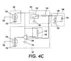
- FIG. 4Cillustrates another preferred electronic embodiment of the components shown in FIG. 4A .
- the electrical to optical converter 122further comprises a reference signal source 140 used to calibrate the received signal.
- the reference signal sourcecomprises a resistor connected to the optical to electrical converter 104 and to the a preamplifier 130 .
- a constant signalis used for the reference calibration signal.
- the constant reference signalis added to the received signal.
- a saw-tooth signal generatoris used for the reference signal source 140 .
- switch 106is preferably a multi-state switch, used to select which of several coils 108 is to have their signals passed to the electrical to optical converter 122 .
- the signal that the switch 106 receives from the optical to electrical converter 104provides information indicating which of the coils 108 to connect to the electrical to optical converter 122 . This is accomplished, e.g. by assigning different voltage levels to different receiver coils. For example, if the coils 108 consist of two different receiver coils (not shown), then the switch 106 is preferably a three state switch. Then an absence of any voltage from the optical to electrical converter 104 indicates the switch 106 is closed and that no receiver coil is connected to the electrical to optical converter 122 .
- the switch 106connects receiver coil # 1 (not shown) to the electrical to optical converter 122 . Finally, if a voltage between 3 ⁇ 4 and 1 Volts is applied to switch 106 then the switch 106 connects receiver coil # 2 (not shown) to the electrical to optical converter 122 .
- the electronic assembly 28is connected to three fiber optic strands 152 , 154 , 156 of the fiber optic cable assembly 26 of FIG. 1 . Additionally, the electronic assembly 28 is connected to the receiver coil(s) 170 via line 168 .
- the fiber optic strand 152carries optical signals to the detuning assembly 164 .
- the detuning assembly 164may comprise, e.g. photo resistors and/or other optically active components so arranged and so connected to the receiver coil(s) 170 as to change the resonance frequency of the receiver coil(s) 170 depending on the presence or absence of light in said fiber optic strand 152 . See, for example, the article “An Optical System for Wireless Detuning of Parallel Resonant Circuits” by E. Y. Wong, et. al., Journal Of Magnetic Resonance Imaging, 12:632-638 (2000) for one such detuning assembly.
- detuning assembly 164may comprise a switch activated by the presence or absence of a light in the optic strand 152 .
- the fiber optic strand 154is used to deliver optical power to the optical to electrical converter 158 .
- Optical to electrical converter 158may comprise, e.g., a photovoltaic cell which converts the delivered laser light into an electrical potential difference suitable for powering other electronic components within the electronic assembly 28 .
- the optical to electrical converter 158is connected to the electrical to optical converter 162 via line 160 .
- the electrical to optical converter 162is used to amplify and convert the electrical signal received in the coil(s) 170 into an optical signal and to transmit said optical signal through fiber optic strand 156 .
- the optical signal sent through fiber optic strand 156is a digital optical signal.
- the optical signal sent through fiber optic strand 156is an analog optical signal.
- the optical to electrical converter 158is further connected to the detuning component 164 to deliver electrical power to this component of the electronic assembly 28 .
- the components of the electronic assembly 28 of FIG. 1is shown.
- the receiver coil(s) 222is connected to the electronic assembly 28 via line 224 .
- the fiber optic strand 202carries a modulated laser light. This laser light is used to produce electrical power for the other electrical components in the electronic assembly 28 as well as to provided control signals suitable for controlling the decoupling circuit 216 .
- the laser light traveling through fiber strand 202is converted to an electrical signal by the optical to electrical converter 206 .
- the optical to electrical converter 206may comprise, e.g., a photovoltaic cell.
- the converted signalis passed on to the command extraction component 210 via line 208 where it is filtered for a detuning command as well as to provide power to other components within the electronic assembly 28 . Any detuning command signals are sent to the decoupling component 216 via line 212 .
- the power connection for the electrical to optical converteris provided by line 214 .
- the decoupling component 216may require electrical power. This be provided to it via optional line 226 .
- the decoupling component 216consists of a switch which is opened when a potential difference is provided to it via line 212 and is closed in the absence of a potential difference.
- the decoupling component 216comprises at least one capacitor whose capacitance changes with the application of a potential difference. In this way, the signals from line 212 change the capacitance of the receiving coil(s) 222 . Thus the coils are tuned and de-tuned to receive and/or not to receive signals in a predetermined frequency range.
- the catheter assembly 12 of FIG. 1can be utilized with any of a number of different magnetic resonance systems 10 of FIG. 1 , including systems utilizing 0.5 Tesla through 7.5 Tesla magnetic fields.
- the receiving coils 222are tuned to receive a signal, or in the case of switching when the switch is opened, the received signals are passed to the electrical to optical converter 218 via conducting line 220 .
- the electrical to optical converter 218is delivered power via line 214 .
- the received signalis converted to an optical signal by the electrical to optical converter 218 which is in turn sends the optical signal through fiber optic strand 204 .
- the electrical to optical converter 218can comprise a preamp, a reference signal generator, and other electrical components.
- the electronic assembly 28comprises electrical components, as in FIG. 6 , contained within an electromagnetic shielding encasement 252 .
- the electromagnetic shielding encasement 252comprises a coating of nanomagnetic particulate material (not shown) so designed as to respond to an electrostatic or time-varying magnetic field or effect, in a manner similar to that of liquid crystal display (LCD) materials. More specifically, these nanomagnetic particulate materials (not shown) are designed to shift alignment and to effect switching from a magnetic shielding orientation to a non-magnetic shielding orientation when a voltage is applied.
- Signal and power extraction element 210preferably has means for providing a voltage to the shielding encasement 252 via line 254 .
- the electromagnetic shielding encasement 252 of FIG. 7may comprise a Faraday cage. In another embodiment (not shown), the electromagnetic shielding encasement 252 may comprise superparamagnetic material.
- catheter assembly 12 of FIG. 1comprises additional means for allowing the positional tracking of the catheter assembly's 12 distal end 16 during a magnetic resonance procedure, e.g. during a magnetic resonance imaging procedure.
- the cathetermay be so manufactured as to have narrow rings (not shown), e.g. having a length from about 0.5 millimeter to about 1 millimeter, equally spaced along the length of the catheter assembly 12 .
- the rings (not shown)may be of a material, (e.g. gadolinium or other appropriate material) or combination of materials known to those skilled in the art which are visible in a magnetic resonance images without significantly distorting the applied magnetic fields in the immediate vicinity of the receiving coil(s) or antenna 30 .
- a single optic strand 102is used for both transporting the optical command/gating signals 304 from the optical interface assembly 34 of FIG. 1 to the electronic assembly 28 as well as for transporting optical encoded signals 302 received from the coils 108 to the optical interface assembly 34 of FIG. 1 .
- an optical filter/mirror component 310is added to the electronic assembly 28 .
- the electrical to optical converter 122receives an electrical signal 110 from the coil(s) 108 and converts it into an optical signal 302 .
- Said optical signal 302may be either a digital or an analog optical signal.
- Optical signal 302is passed on to the optical filter/mirror component 310 which directs the optical signal 302 through the fiber optic strand 102 .
- Optical signal 302will have a fixed wavelength A 1 while the optical command/gating signals 304 will have a different wavelength A 2 .
- the specific wavelengths to be useddepends in part on the specific implementation of the optical filter/mirror 310 .
- FIG. 8Bis a circuit diagram implementation for the embodiment depicted in FIG. 8A .
- the optical filter/mirror 310is implemented by element 306 , which can be, e.g. a dichroic color filter, or a hot mirror, or a cold mirror.
- element 306can be, e.g. a dichroic color filter, or a hot mirror, or a cold mirror.
- these optical elementsare ready available for separating (reflecting and passing) and combining optical signals of different wavelengths.
- optical filter/mirror 310is a be a hot mirror 306 set at a 45 degrees angle to the incident optical signals 302 and 304 and which passes wavelengths, e.g., between about 450 nanometers to about 650 nanometers and reflects wavelengths, e.g., in the range of about 750 nanometers to about 1000 nanometers. Then wavelength A 1 of optical signal 302 can be selected to be between 750 nanometers and 1000 nanometers so that optical signal 302 is reflected by hot mirror 306 while the wavelength A 2 of optical signal 304 can be selected to be between 450 nanometers and 650 nanometers so that optical signal 304 is passed through hot mirror 306 .
- wavelength A 1 of optical signal 302can be selected to be between 750 nanometers and 1000 nanometers so that optical signal 302 is reflected by hot mirror 306
- the wavelength A 2 of optical signal 304can be selected to be between 450 nanometers and 650 nanometers so that optical signal 304 is passed through hot mirror 306
- FIG. 8Cdepicts the components for the optical interface assembly 34 for the case in which one optic strand 102 is used within the catheter assembly 12 for transporting both the magnetic resonance received signal 302 and the command/gating signal 304 .
- the optical interface assembly 34comprises an optical mirror/filter which can be, e.g. a dichroic color filter, or a hot mirror, or a cold mirror.
- optical tilter/mirror 320is a cold mirror set at a 45 degree angle to the incident optical signals 302 and 304 and which reflects wavelengths, e.g., between about 450 nanometers to about 650 nanometers and passes wavelengths, e.g., in the range of about 750 nanometers to about 1000 nanometers.
- wavelength A 1 of optical signal 302is preferably selected to be between about 450 nanometers and 650 nanometers so that optical signal 302 passes through cold mirror 320
- wavelength A 2 of optical signal 304is preferably selected to be between about 750 nanometers and 1000 nanometers so that optical signal 304 is reflected into optical connector 54 by cold mirror 306 .
- an assembly for delivering optical signalscomprising a nuclear magnetic resonance system; an optical interface assembly electrically connected to the nuclear magnetic resonance system, and a catheter assembly connected to the optical interface assembly.
Landscapes
- Physics & Mathematics (AREA)
- Health & Medical Sciences (AREA)
- General Physics & Mathematics (AREA)
- Condensed Matter Physics & Semiconductors (AREA)
- General Health & Medical Sciences (AREA)
- Life Sciences & Earth Sciences (AREA)
- Pathology (AREA)
- Engineering & Computer Science (AREA)
- Nuclear Medicine, Radiotherapy & Molecular Imaging (AREA)
- Computer Networks & Wireless Communication (AREA)
- Surgery (AREA)
- Medical Informatics (AREA)
- Molecular Biology (AREA)
- Heart & Thoracic Surgery (AREA)
- Animal Behavior & Ethology (AREA)
- Radiology & Medical Imaging (AREA)
- Public Health (AREA)
- Veterinary Medicine (AREA)
- Biomedical Technology (AREA)
- Biophysics (AREA)
- High Energy & Nuclear Physics (AREA)
- Magnetic Resonance Imaging Apparatus (AREA)
Abstract
Description
This application is a divisional application of patent application U.S. Ser. No. 10/202,921, filed on Jul. 25, 2002, now U.S. Pat. No. 6,925,322, the disclosure of which is incorporated herein by reference.
1. Field of the Invention
An invasive apparatus for receiving a magnetic resonance signal from within a body and providing means for transmitting the signal to the received signal input channel of standard magnetic resonance systems.
2. Description of Related Art
Magnetic resonance imaging (“MRI”) has been developed as an imaging technique adapted to obtain both images of anatomical features of human patients as well as some aspects of the functional activities and characteristics of biological tissue. These images and/or functional and/or chemical measurements have medical diagnostic value in determining the state of the health of the tissue examined.
In an MRI process, a patient is typically aligned to place the portion of the patient's anatomy to be examined in the imaging volume of the MRI apparatus. Such an MRI apparatus typically comprises a primary magnet for supplying a constant magnetic field (B0) which, by convention, is along the z-axis and is substantially homogeneous over the imaging volume and secondary magnets that can provide linear magnetic field gradients along each of three principal Cartesian axes in space (generally x, y, and z, or x1, x2and x3, respectively). A magnetic field gradient (ΔB0/Δxi) refers to the variation of the field along the direction parallel to B0with respect to each of the three principal Cartesian axes, xi. The apparatus also comprises one or more RF (radio frequency) coils which provide excitation and detection of the MRI signal. Additionally or alternatively, detection coils may be designed into the distal end of a catheter to be inserted into a patient. When such catheters are employed, their proximal ends are connected to the signal input channel of the magnetic resonance imaging device. The detected signal is transmitted along the length of the catheter from the receiving antenna and/or receiving coil in the distal end to the MRI input channel connected at the proximal end.
The insertion of metallic wires into a body, e.g. catheters and guidewires, while in a magnetic resonance imaging environment, poses potentially deadly hazards to the patient through excessive heating of the wires, e.g. in excess of 74° C. in some studies. M. K. Konings, et. al, in “Catheters and Guidewires in Interventional MRI: Problems and Solutions”, MEDICA MUNDI 45/1 March 2001, list three ways in which conductors may heat up in such environments: 1) eddy currents, 2) induction loops, and 3) resonating RF transverse electromagnetic (TEM) waves along the length of the conductors. They write “Because of the risks associated with metal guidewires, and catheters with metal conductors, in the MRI environment, there is an urgent need for a non-metallic substitute, both for guidewires and for signal transfer.” They further propose the use of “ . . . a full-glass guidewire with a protective polymer coating . . . . ”
The tracking and placement of a catheter within a body is an important aspect of using catheters in magnetic resonance imaging procedures. Considering the dangers inherent in the use of metallic wires in the magnetic resonance imaging environment, as mentioned above, M. K. Konings, et. al., in their paper “Development of an MR-Safe Tracking Catheter With a Laser-Driven Tip Coil” describe the design of a tracking catheter “ . . . using an optical fiber with a light-diffusing tip segment to transport laser energy through the catheter. This energy is converted to a DC current running through a small coil at the catheter tip. Our method is inherently MR-safe since the use of long conducting wires is avoided.”
From the paper “An Optical System for Wireless Detuning of Parallel Resonant Circuits” by E. Y. Wong, et. al., in the Journal of Magnetic Resonance Imaging 12:632–638 (2000), it is pointed out that typically when a catheter coil is used in magnetic resonance imaging, it is necessary to detune the coil away from the frequency of the magnetic resonance imaging system during the transmission of the magnetic resonance imaging pulse sequence. The authors write “In all MRI experiments in which local coils are used for signal reception, coil detuning is necessary during transmission to prevent high voltages from being induced in the receiver coil and other electronic components including the receiver preamplifier. The potentially high voltages and currents, as well as the induced electric fields, pose a safety hazard for the patient, . . . , and disrupt the desired uniform excitation field generation required for excitation; this may lead to particular localized effects in interventional or intravascular MR imaging in which small coils are used.” This paper further describes the use of a complex design consisting of fiber optic cable and photoresistors to overcome these problems.
By providing a catheter with an MR receiving coil or antenna in the distal end, the coil or antenna can be placed closer to the tissue which is to be imaged or analyzed. Thus the detected signal is less susceptible to radio frequency noise. Additionally, the level of detail that can be resolved (the resolution of the image, spectrum, or other data obtained) is increased by the use of catheter coils.
Thus, it is desirable to provide an apparatus such as a catheter which can be used with a magnetic resonance system for insertion and positioning of an magnetic resonance receiver coil or antenna within a body which is not susceptible to the heating, noise pickup, electrostatic buildup and/or other hazards associated with the use of conductors in a magnetic resonance environment.
In accordance with the present invention, there is provided an assembly for delivering optical signals comprising a nuclear magnetic resonance system; an optical interface assembly electrically connected to the nuclear magnetic resonance system, the optical interface assembly comprising a first laser for producing laser optical signals, an interface optical to electrical signal convertor, and an interface optical connector assembly; and a catheter assembly comprising a proximal end, a distal end, and a catheter optical connector assembly disposed at the proximal end and connected to the interface optical connector assembly of the optical interface assembly, a fiber optic cable assembly, an electronics assembly disposed at the distal end comprised of a catheter electrical to optical signal convertor and a catheter optical to electrical signal convertor, and a first receiving coil disposed at the distal end. The laser optical signals received through the fiber optic cable assembly from the first laser are converted into catheter electrical signals by the catheter optical to electrical signal convertor; and the first receiving coil is adapted to receive electromagnetic signals and deliver coil electrical signals to the electronics assembly of the catheter assembly. The coil electrical signals are converted by the catheter electrical to optical signal convertor to catheter optical signals and the catheter optical signals are delivered through the fiber optic cable assembly to the interface optical to electrical signal convertor; and the catheter optical signals are converted by the interface optical to electrical signal convertor into interface electrical signals and are delivered to the nuclear magnetic resonance system.
The invention will be described by reference to the following drawings, in which like numerals refer to like elements, and in which:
The present invention will be described in connection with a preferred embodiment, however, it will be understood that there is no intent to limit the invention to the embodiment described. On the contrary, the intent is to cover all alternatives, modifications, and equivalents as may be included within the spirit and scope of the invention as defined by the appended claims.
In one embodiment, the apparatus of this patent application comprises the structure shown inFIG. 1 . Referring toFIG. 1 , a standard magnetic resonance system10 (e.g. the GE Signa Infinity 1.5Tesla system, or Siemens Symphony 1.5 Tesla system) comprises means for generating and controllingmagnetic fields 18, which may comprise electromagnets and/or permanent magnets, aprogrammable logic unit 20, areceiver input channel 22 and a command/gating output channel 32. Thereceiver input channel 22 is used to pass the detected signals to the programmable logic unit for image reconstruction. The command/gating output channel 32 is used to provide at minimum gating signals synchronized to the application of the gradient magnetic fields of themagnetic resonance system 10.
Continuing to refer toFIG. 1 , and to the embodiment depicted therein, anoptical interface assembly 34 is connected to thereceiver input channel 22 and to the command/gating output channel 32 of themagnetic resonance system 10. Theoptical interface assembly 34 converts the electrical command/gating signals of themagnetic resonance system 10 issued through the command/gating output channel 32 into optical signals and transmits these optical signals through thecatheter assembly 12. Theoptical interface assembly 34 also converts the optical signals received from thecatheter 12 into electrical signals suitable for the magnetic resonance system's10receiver input channel 22.
Continuing to refer toFIG. 1 , theoptical interface assembly 34 is connected to thecatheter assembly 12 throughoptical connector assembly 36 within theoptical interface assembly 34 andoptical connector assembly 24 in theproximal end 14 of thecatheter assembly 12. Optical connectors are well known to those skilled in the arts. Reference may be had, e.g., to U.S. Pat. No. 6,149,313 (Gender selectable fiber optic connector and associated fabrication method), which discloses “A gender selectable fiber optic connector is provided which can be readily converted between male and female configurations following assembly and polishing of the connector.” U.S. Pat. No. 5,619,605 (Optical connector) discloses “A novel optical connector that includes the following: an optical connector ferrule which is capable of fixing optical fibers; optical fibers fixed onto the optical connector ferrule, such that the end surfaces of the optical fibers project beyond an end surface of the optical connector ferrule; an adhesive for fixing the optical fibers onto the optical connector ferrule; and a member whose Young's Modulus is less than that of the optical fiber and is provided to an area on the end surface of the optical connector ferrule surrounding, at a minimum, the projected portions of the optical fibers.” Further reference may be had to U.S. Pat. No. 4,934,785 (Optical fiber connector), U.S. Pat. No. 5,963,690 (Optical fiber connector), U.S. Pat. No. 6,367,984 (Optical fiber adapter), U.S. Pat. No. 6,179,482 (Optical connector and housing for optical connector), U.S. Pat. No. 5,590,227 (Optical connector apparatus), U.S. Pat. No. 5,214,730 (Multifiber optical connector plug with low reflection and low insertion loss). The entire disclosure of each of these United States patents is hereby incorporated by reference into this specification.
Referring again toFIG. 1 , theoptical connector assemblies catheter assembly 12 to be detached from theoptical interface assembly 34. Reference may be made to U.S. Pat. No. 5,631,988 (Parallel optical interconnect) which discloses “An optical interconnect is disclosed that couples multiple optical fibers to an array of optoelectronic devices. The interconnect includes a multiple optical fiber connector and an optoelectronic board. The multiple fiber connector can be mechanically attached to or detached from the board.” U.S. Pat. No. 4,804,244 (Connector for optical fiber) discloses “An optical fiber connector in which an optical fiber and an optical conversion element are detachably coupled together, and optical fibers are mutually coupled together.” The entire disclosure of each of these United States patents is hereby incorporated by reference into this specification.
Continuing to refer toFIG. 1 , theoptical connectors 24 are fabricated to one end of the fiberoptic cable assembly 26. The fiberoptical cable assembly 26 may comprise one or more fiber optical strands suitable for transmitting optical signals from thedistal end 16 of thecatheter assembly 12 to theproximal end 14 of thecatheter assembly 12. Such fiberoptic cable assembly 26 is typical of prior art optical cable assemblies. Reference may be had, e.g., to U.S. Pat. No. 4,784,461 (optical cable with improved strength), U.S. Pat. No. 6,259,843 (optical cable), U.S. Pat. No. 5,611,016 (dispersion balanced optical cable), U.S. Pat. No. 4,911,525 (optical communications cable), U.S. Pat. No. 4,798,443 (optical cable), U.S. Pat. No. 5,634,720 (multi-purpose multi-parameter cardiac catheter), and the like. The entire disclosure of each of these United States patents is hereby incorporated by reference into this specification.
Additionally, fiberoptic cable assembly 26 may comprise one or more lumens (not shown) suitable for the transport of a gas, e.g., air, or a liquid, e.g., a soluble drug in a saline or other solution, through the length of thecatheter assembly 12. Additionally, said lumens (not shown), may allow a flexible solid material, e.g. a flexible plastic rod, to be maneuvered through the length of thecatheter assembly 12. Such lumens (not shown) are well known to those skilled in the arts of catheter assemblies and are typically used to extend or retract position stabilizing balloons (not shown) or other position stabilizing means built into thecatheter assembly 12. Additionally, said lumens (not shown) are used for performing biopsies, delivering stents, delivering drugs, and/or for other therapeutic purpose and/or medical procedures. Such lumens may be made from nonconductive, nonmagnetic material, e.g. plastics, or silicon dioxide, etc. Reference to such catheter assemblies may be made to International patent publication PCT WO 01/74241 A2 (Systems And Methods For Evaluating The Urethra And The Periurethral Tissues), U.S. Pat. No. 6,056,721 (Balloon catheter and method), U.S. Pat. No. 5,575,772 (Albation catheters), U.S. Pat. No. 6,146,415 (Stent delivery system), and the like. The entire disclosure of each of these United States patents is hereby incorporated by reference into this specification.
Continuing to refer toFIG. 1 and the embodiment depicted therein, the fiberoptic cable assembly 26 is connected to anelectronic assembly 28 within thedistal end 16 of thecatheter assembly 12. Theelectronic assembly 28 provides the means for converting the electrical signal received by the pickup coil(s)30 into an optical signal and to transmit said optical signal through the fiberoptic cable assembly 26 to theproximal end 14 of thecatheter assembly 12. Additionally,electronic assembly 28 may receive optically encoded command/gating signals which originate as electrical signals from the magnetic resonance system's10 command/gating output channel 32, which are converted to optical command/gating signals in theoptical interface 34. Said command/gating signals may be used by theelectronic assembly 28 to, e.g. select which of several receiver coils30 is to be utilized, tune and/or detune receiver coils30 into or away from a frequency range, activate a gating switch connected to receiver coils30, etc. Additionally or alternatively, said optical command/gating signals may be converted in total or in part into electrical power in theelectronic assembly 28.
Continuing to refer toFIG. 1 , the receiving catheter coils30 may be any one of or a multiplicity of several coils and/or antenna used to receive signals from the tissues that have been excited by themagnetic resonance system 10. Various catheter coil designs are well known to those skilled in the arts. Reference may be had to, e.g., U.S. Pat. No. 6,263,229 (Miniature Magnetic Resonance Catheter Coils and Related Methods) which discloses “The present invention provides several embodiments of methods of making magnetic resonance catheter coils which include employing a flexible electrically insulative base member, depositing an electrically conductive material on the base member in a predetermined pattern to create at least one pair of generally parallel electrically conductive coil elements which are electrically connected to each other.” U.S. Pat. No. 5,928,145 (Method of magnetic resonance imaging and spectroscopic analysis and associated apparatus employing a loopless antenna) discloses “The invention provides a method for magnetic resonance imaging and spectroscopic analysis of a specimen which includes positioning the specimen within a main magnetic field and introducing an antenna having a loopless antenna portion in close proximity to the specimen.” U.S. Pat. No. 5,699,801 (Method of internal magnetic resonance imaging and spectroscopic analysis and associated apparatus) discloses “The invention provides a method for magnetic resonance imaging and spectroscopic analysis of the interior of a specimen which includes positioning the specimen within a main magnetic field, introducing an invasive probe having an elongated receiver coil into or adjacent to the specimen with the coil having at least one pair of elongated electrical conductors, preferably, generally parallel to each other disposed within a dielectric material and having a pair of ends electrically connected to each other. RF pulses are provided to the region of interest to excite magnetic resonance signals, gradient magnetic pulses are applied to the region of interest with the receiver coil receiving magnetic resonance signals and emitting responsive output signals which may be processed by a computer to provide image information for display in a desired manner.” The entire disclosure of each of these United States patents is hereby incorporated by reference into this specification.
Continuing to refer toFIG. 2 and to the embodiment depicted therein, the connection lines64 and66 are used to connect theoptical interface assembly 34 to the magnetic resonance system's (10 ofFIG. 1 )signal input channel 22 ofFIG. 1 and to the command/gating output channel 32 ofFIG. 1 respectively. Theconnection line 64 is connected to the optical toelectrical signal converter 52 component of theoptical interface assembly 34. Optical toelectrical signal converter 52 may be, e.g., a standard photodiode operating in a photoconductive mode. One such photodiode is UDT Sensors Inc.'s High Speed Silicon Fiber Optic Detector, part number PIN-HR020. In another preferred embodiment (not shown), optical toelectrical signal converter 52 comprises electrical amplification means (not shown), e.g. and operational amplifier, and other electronic components (not shown) suitable for reproducing the original electrical signal and for matching the impedance and/or other electrical characteristics of thesignal input channel 22 ofFIG. 1 of themagnetic resonance system 10 ofFIG. 1 .
Continuing to refer toFIG. 2 , theconnection line 66 is connected to aprogrammable logic unit 58, which may be, e.g. a programmable computer, which is used to receive electrical command/gating signals from themagnetic resonance system 10 ofFIG. 1 and to control the conversion of such electrical command/gating signals into optical command signals. In one embodiment, as depicted inFIG. 2 , theprogrammable logic unit 58 is used to modulate alaser 60, such modulation in the laser's60 light representing the converted command signal. Thelaser 60 may be, e.g., Sanyo's Laser Diode 785 nanometer, 25 milliWatt, part number DL4140-001. Additionally, thelaser 60 is used to supply power through thecatheter assembly 12 to theelectronic assembly 28 ofFIG. 1 .
Referring toFIG. 2 , the optical toelectrical signal converter 52 component of theoptical interface assembly 34 is used to convert the received optical signal into an electrical signal. The received optical signal may be a digital encoding of the original analog electrical signal from thecoils 30 ofFIG. 1 , or may be analog signals representing said original electrical signal. Such analog signals may be, e.g. modulated signals in the range of about 10 mega Hertz to about 1,000 mega Hertz. The converted optical to electrical signal is then sent on to the magnetic resonance system's (10 ofFIG. 1 )signal input channel 22 ofFIG. 1 viaelectrical connection 64. The optical signal received by the optical toelectrical signal converter 52 originates as a picked up electrical signal induced in thecoils 30 ofFIG. 1 located in thedistal end 16 ofFIG. 1 of thecatheter assembly 12. Said electrical signal is converted to an optical signal by theelectronic assembly 28 ofFIG. 1 located in thedistal end 16 ofFIG. 1 of thecatheter assembly 12.
Additionally, the optical signal sent to the optical toelectrical converter 52 may comprise a reference optical signal component in addition to the optically encoded received signal. Such reference signal component may be, e.g., a constant optical signal, or a saw-tooth signal. The reference component of the optical signal is used for calibration of the optical signals. The bending of thecatheter assembly 12 as well as the electrical components used to generate the optical signals may introduce nonlinear effects into the produced optical signal. Such nonlinearities may be quantified by the introduction of said reference optical signal component. In the case where said reference optical signal is utilized, optical toelectrical converter 52 contains means (not shown) for utilizing said reference optical signal to correct any nonlinearities induced into the received optical signal.
Continuing to refer toFIG. 2 and to the embodiment depicted therein, apower supply 56 is connected to all components of theoptical interface assembly 34 which require power to operate.Power supply 56 may be, e.g., an AC to DC power converter connected to an external United States' standard 120Volt 60 Hertz wall socket. Alternatively,power supply 56 may be a system of one or more batteries.
In another preferred embodiment, depicted inFIG. 3 , threeoptical connectors proximal end 14 ofcatheter assembly 12.Optical connectors optical connectors connector assembly 24 of theproximal end 14 of thecatheter assembly 12. In this embodiment, the fiberoptic cable assembly 26 ofFIG. 1 preferably is comprised of at least three optical fiber strands. Eachstrand optic cable assembly 26 ofFIG. 1 services a different communication need.
Continuing to refer toFIG. 3 ,optical connectors optical interface assembly 34 to the receivedsignal strand 82 of the fiberoptic cable assembly 26 ofFIG. 1 .Optical connectors optical interface assembly 34 to thecommand signal strand 84 of the fiberoptic cable assembly 26 ofFIG. 1 .Optical connectors optical interface assembly 34 to the opticalpower transmission strand 86 of the fiberoptic cable assembly 26 ofFIG. 1 . The opticalpower transmission strand 86 is used to deliver power to thedistal end 16 ofFIG. 1 of thecatheter assembly 12 and in particular to theelectronic assembly 28 ofFIG. 1 .
Continuing to refer toFIG. 3 , the laser74 is used to generate optical command/gating signals. These optical command/gating signals are used by theelectronic assembly 28 ofFIG. 1 to tune and/or detune and/or gate (connect/disconnect) and/or select the receiving coils30.Laser 78 is used to generate optical power for use by theelectronic assembly 28 ofFIG. 1 in thedistal end 16 ofFIG. 1 of thecatheter assembly 12. Bothlasers 74 and78 are controlled by the programmablelogical unit 58 which may be, e.g. a programmable computer.
Referring toFIG. 4A , and to the embodiment depicted therein, the components of theelectronic assembly 28 ofFIG. 1 are shown. Anoptical fiber strand 102 is connected to an optical toelectrical converter 104, which is connected to aswitch 106 vialine 114. The optical toelectrical converter 104 may be, e.g., a silicon photovoltaic cell. One such silicon photovoltaic cell can be UDT Sensors Inc.'s Planar Diffused Silicon Photodiode part number S-4CL. In one preferred method of operation, when a laser light is present at the optical toelectrical converter 104, an electrical potential is applied to theswitch 106, theswitch 106 is open. In the absence of the laser light, and thus in the absence of an electrical potential, theswitch 106 is closed.
The coil(s)108 are connected to theswitch 106 vialine 116. The coil(s)108 may comprise electronic components, e.g. one or more capacitors, suitable to tune the receiving coil(s)108 to a preferred electromagnetic frequency as well as to connect the coil(s)108 to the electrical ground to prevent electrostatic charge from building up, as is known to those skilled in the art.
In another embodiment, and continuing to refer toFIG. 4A ,switch 106 is preferably a multi-state switch, used to select which ofseveral coils 108 is to have their signals passed to the electrical tooptical converter 122. The signal that theswitch 106 receives from the optical toelectrical converter 104 provides information indicating which of thecoils 108 to connect to the electrical tooptical converter 122. This is accomplished, e.g. by assigning different voltage levels to different receiver coils. For example, if thecoils 108 consist of two different receiver coils (not shown), then theswitch 106 is preferably a three state switch. Then an absence of any voltage from the optical toelectrical converter 104 indicates theswitch 106 is closed and that no receiver coil is connected to the electrical tooptical converter 122. If a voltage between the range ˜ to Yz Volts is applied to theswitch 106, then theswitch 106 connects receiver coil #1 (not shown) to the electrical tooptical converter 122. Finally, if a voltage between ¾ and 1 Volts is applied to switch106 then theswitch 106 connects receiver coil #2 (not shown) to the electrical tooptical converter 122.
In another preferred embodiment, as depicted inFIG. 5 , theelectronic assembly 28 is connected to threefiber optic strands optic cable assembly 26 ofFIG. 1 . Additionally, theelectronic assembly 28 is connected to the receiver coil(s)170 vialine 168.
Continuing with the preferred embodiment depicted inFIG. 5 , thefiber optic strand 152 carries optical signals to thedetuning assembly 164. Thedetuning assembly 164 may comprise, e.g. photo resistors and/or other optically active components so arranged and so connected to the receiver coil(s)170 as to change the resonance frequency of the receiver coil(s)170 depending on the presence or absence of light in saidfiber optic strand 152. See, for example, the article “An Optical System for Wireless Detuning of Parallel Resonant Circuits” by E. Y. Wong, et. al., Journal Of Magnetic Resonance Imaging, 12:632-638 (2000) for one such detuning assembly. In another embodiment, detuningassembly 164 may comprise a switch activated by the presence or absence of a light in theoptic strand 152.
Continuing withFIG. 5 , thefiber optic strand 154 is used to deliver optical power to the optical toelectrical converter 158. Optical toelectrical converter 158 may comprise, e.g., a photovoltaic cell which converts the delivered laser light into an electrical potential difference suitable for powering other electronic components within theelectronic assembly 28.
The optical toelectrical converter 158 is connected to the electrical tooptical converter 162 vialine 160. The electrical tooptical converter 162 is used to amplify and convert the electrical signal received in the coil(s)170 into an optical signal and to transmit said optical signal throughfiber optic strand 156. In one embodiment the optical signal sent throughfiber optic strand 156 is a digital optical signal. In another embodiment the optical signal sent throughfiber optic strand 156 is an analog optical signal.
In another embodiment, not shown, the optical toelectrical converter 158 is further connected to thedetuning component 164 to deliver electrical power to this component of theelectronic assembly 28.
Referring toFIG. 6 and to the preferred embodiment depicted therein, the components of theelectronic assembly 28 ofFIG. 1 is shown. In this embodiment there are twofiber optic strands electronic assembly 28. Additionally, the receiver coil(s)222 is connected to theelectronic assembly 28 vialine 224.
Thefiber optic strand 202 carries a modulated laser light. This laser light is used to produce electrical power for the other electrical components in theelectronic assembly 28 as well as to provided control signals suitable for controlling thedecoupling circuit 216. The laser light traveling throughfiber strand 202 is converted to an electrical signal by the optical toelectrical converter 206. The optical toelectrical converter 206 may comprise, e.g., a photovoltaic cell. The converted signal is passed on to thecommand extraction component 210 vialine 208 where it is filtered for a detuning command as well as to provide power to other components within theelectronic assembly 28. Any detuning command signals are sent to thedecoupling component 216 vialine 212. The power connection for the electrical to optical converter is provided byline 214. In one embodiment thedecoupling component 216 may require electrical power. This be provided to it viaoptional line 226.
In one embodiment, thedecoupling component 216 consists of a switch which is opened when a potential difference is provided to it vialine 212 and is closed in the absence of a potential difference. In one embodiment, thedecoupling component 216 comprises at least one capacitor whose capacitance changes with the application of a potential difference. In this way, the signals fromline 212 change the capacitance of the receiving coil(s)222. Thus the coils are tuned and de-tuned to receive and/or not to receive signals in a predetermined frequency range. Additionally, by actively adjusting the capacitance, thecatheter assembly 12 ofFIG. 1 can be utilized with any of a number of differentmagnetic resonance systems 10 ofFIG. 1 , including systems utilizing 0.5 Tesla through 7.5 Tesla magnetic fields.
Continuing to refer toFIG. 6 , when the receivingcoils 222 are tuned to receive a signal, or in the case of switching when the switch is opened, the received signals are passed to the electrical tooptical converter 218 via conductingline 220. The electrical tooptical converter 218 is delivered power vialine 214. The received signal is converted to an optical signal by the electrical tooptical converter 218 which is in turn sends the optical signal throughfiber optic strand 204. The electrical tooptical converter 218 can comprise a preamp, a reference signal generator, and other electrical components.
Referring toFIG. 7 and to the embodiment depicted therein, theelectronic assembly 28 comprises electrical components, as inFIG. 6 , contained within anelectromagnetic shielding encasement 252. Theelectromagnetic shielding encasement 252 comprises a coating of nanomagnetic particulate material (not shown) so designed as to respond to an electrostatic or time-varying magnetic field or effect, in a manner similar to that of liquid crystal display (LCD) materials. More specifically, these nanomagnetic particulate materials (not shown) are designed to shift alignment and to effect switching from a magnetic shielding orientation to a non-magnetic shielding orientation when a voltage is applied. Signal andpower extraction element 210 preferably has means for providing a voltage to the shieldingencasement 252 vialine 254.
In another embodiment (not shown), theelectromagnetic shielding encasement 252 ofFIG. 7 may comprise a Faraday cage. In another embodiment (not shown), theelectromagnetic shielding encasement 252 may comprise superparamagnetic material.
In another embodiment of this invention,catheter assembly 12 ofFIG. 1 comprises additional means for allowing the positional tracking of the catheter assembly's12distal end 16 during a magnetic resonance procedure, e.g. during a magnetic resonance imaging procedure. In this case, the catheter may be so manufactured as to have narrow rings (not shown), e.g. having a length from about 0.5 millimeter to about 1 millimeter, equally spaced along the length of thecatheter assembly 12. The rings (not shown) may be of a material, (e.g. gadolinium or other appropriate material) or combination of materials known to those skilled in the art which are visible in a magnetic resonance images without significantly distorting the applied magnetic fields in the immediate vicinity of the receiving coil(s) orantenna 30.
In another preferred embodiment, as depicted inFIG. 8A , asingle optic strand 102 is used for both transporting the optical command/gating signals304 from theoptical interface assembly 34 ofFIG. 1 to theelectronic assembly 28 as well as for transporting optical encodedsignals 302 received from thecoils 108 to theoptical interface assembly 34 ofFIG. 1 . In this embodiment, and continuing to refer toFIG. 8A , an optical filter/mirror component 310 is added to theelectronic assembly 28. The electrical tooptical converter 122 receives anelectrical signal 110 from the coil(s)108 and converts it into anoptical signal 302. Saidoptical signal 302 may be either a digital or an analog optical signal.Optical signal 302 is passed on to the optical filter/mirror component 310 which directs theoptical signal 302 through thefiber optic strand 102.Optical signal 302 will have a fixed wavelength A1 while the optical command/gating signals304 will have a different wavelength A2. The specific wavelengths to be used depends in part on the specific implementation of the optical filter/mirror 310.
Theoptical signal 302 is passed through the optical mirror/tilter to the optical toelectrical converter 52, while the optical command gating/switching signal 304 from the modulatedlaser 60 is reflected by the optical mirror/tilter 320 into theoptical connector 54. In one embodiment, optical tilter/mirror 320 is a cold mirror set at a 45 degree angle to the incidentoptical signals optical signal 302 is preferably selected to be between about 450 nanometers and 650 nanometers so thatoptical signal 302 passes throughcold mirror 320, while wavelength A2 ofoptical signal 304 is preferably selected to be between about 750 nanometers and 1000 nanometers so thatoptical signal 304 is reflected intooptical connector 54 bycold mirror 306.
It is, therefore, apparent that there has been provided, in accordance with the present invention, an assembly for delivering optical signals comprising a nuclear magnetic resonance system; an optical interface assembly electrically connected to the nuclear magnetic resonance system, and a catheter assembly connected to the optical interface assembly. While this invention has been described in conjunction with preferred embodiments thereof, it is evident that many alternatives, modifications, and variations will be apparent to those skilled in the art. Accordingly, it is intended to embrace all such alternatives, modifications and variations that fall within the spirit and broad scope of the appended claims.
Claims (22)
1. An assembly for delivering optical signals comprising a nuclear magnetic resonance system; an optical interface assembly electrically connected to said nuclear magnetic resonance system, said optical interface assembly comprising a first laser for producing laser optical signals, an interface optical to electrical signal convertor, and an interface optical connector assembly; and a catheter assembly comprising a proximal end, a distal end, and a catheter optical connector assembly disposed at said proximal end and connected to said interface optical connector assembly of said optical interface assembly, a fiber optic cable assembly, an electronics assembly disposed at said distal end comprised of a catheter electrical to optical signal convertor and a catheter optical to electrical signal convertor, and a first receiving coil disposed at said distal end, wherein:
a. said laser optical signals received through said fiber optic cable assembly from said first laser are converted into catheter electrical signals by said catheter optical to electrical signal convertor;
b. said first receiving coil is adapted to receive electromagnetic signals and deliver coil electrical signals to said electronics assembly of said catheter assembly;
c. said coil electrical signals are converted by said catheter electrical to optical signal convertor to catheter optical signals and said catheter optical signals are delivered through said fiber optic cable assembly to said interface optical to electrical signal convertor; and
d. said catheter optical signals are converted by said interface optical to electrical signal convertor into interface electrical signals and are delivered to said nuclear magnetic resonance system.
2. The assembly as recited inclaim 1 , wherein said catheter optical to electrical signal convertor is comprised of a photovoltaic cell.
3. The assembly as recited inclaim 1 , wherein said interface optical to electrical signal convertor is comprised of a photodiode.
4. The assembly as recited inclaim 1 , wherein said electronics assembly of said catheter assembly further comprises a switch for blocking or permitting the passage of said coil electrical signals to said catheter electrical to optical signal convertor.
5. The assembly as recited inclaim 4 , wherein said switch is opened by the delivery of light from said first laser to said catheter optical to electrical signal convertor.
6. The assembly as recited inclaim 4 , wherein said assembly further comprises a second receiving coil, and wherein said switch is a multi-state switch used to select which of said first or second receiving coils provides said coil electrical signal to said electronics assembly of said catheter assembly.
7. The assembly as recited inclaim 1 , wherein said catheter electrical to optical signal convertor further comprises a reference signal source.
8. The assembly as recited inclaim 1 , wherein said electronics assembly of said catheter assembly further comprises a detuning assembly adapted to change the resonance frequency of said first receiving coil.
9. The assembly as recited inclaim 8 , wherein said electronics assembly of said catheter assembly further comprises a switch, and said detuning assembly further comprises at least one capacitor whose capacitance changes with the application of a potential difference to said switch.
10. The assembly as recited inclaim 8 , wherein said receiving coil further comprises a single inductive loop coil, and a tuning capacitor.
11. The assembly as recited inclaim 8 , wherein said electronics assembly of said catheter further comprises a command extraction component for filtering a detuning command to said detuning assembly.
12. The assembly as recited inclaim 1 , wherein said first receiving coil is selected from the group consisting of a pickup coil, a single loop coil, a multi-loop coil, a loopless antenna, and a dipole antenna.
13. The assembly as recited inclaim 1 , wherein said first laser is modulated to produce said laser optical signals to said catheter optical to electrical signal convertor.
14. The assembly as recited inclaim 13 , wherein said first laser provides electrical power to said electronics assembly of said catheter and control signals to said electronics assembly of said catheter.
15. The assembly as recited inclaim 1 , wherein said optical interface assembly further comprises a second laser, and wherein said first laser generates optical command/gating signals to said electronics assembly of said catheter and said second laser generates optical power for use by said electronics assembly of said catheter.
16. The assembly as recited inclaim 1 , wherein:
a. said first laser produces laser optical signals at a first wavelength;
b. said catheter electrical to optical signal convertor converts said coil electrical signals to said catheter optical signals, said catheter optical signals being at a second wavelength;
c. said electronics assembly of said catheter assembly further comprises a catheter optical filter/mirror component that delivers said laser optical signals at said first wavelength from said optical interface assembly to said catheter optical to electrical signal convertor, and that delivers said catheter optical signals at said second wavelength from said catheter electrical to optical signal convertor to said optical interface assembly; and
d. said optical interface assembly further comprises an interface optical filter/mirror component that delivers said laser optical signals at said first wavelength from said first laser to said electronics assembly of said catheter assembly, and that delivers said catheter optical signals at said second wavelength from said catheter electrical to optical signal convertor to said interface optical to electrical signal convertor.
17. The assembly as recited inclaim 16 , wherein said catheter optical filter/mirror component reflects said catheter optical signals at said second wavelength to said optical interface assembly, and transmits said laser optical signals at said first wavelength to said catheter optical to electrical signal convertor.
18. The assembly as recited inclaim 16 , wherein said interface optical filter/mirror component reflects said laser optical signals of said first wavelength to said electronics assembly of said catheter assembly, and transmits said catheter optical signals at said second wavelength to said interface optical to electrical signal convertor.
19. The assembly as recited inclaim 18 , wherein said catheter optical filter/mirror component reflects said catheter optical signals at said second wavelength to said optical interface assembly, and transmits said laser optical signals at said first wavelength to said catheter optical to electrical signal convertor.
20. The assembly as recited inclaim 19 , wherein said first wavelength is between about 450 and about 650 nanometers, and said second wavelength is between about 750 and about 1000 nanometers.
21. The assembly as recited inclaim 19 , wherein said a fiber optic cable assembly of said catheter assembly is comprises of a single strand of optical fiber for transmission of said laser optical signals at said first wavelength and said catheter optical signals at said second wavelength.
22. The assembly as recited inclaim 16 , wherein said interface optical filter/mirror component and said catheter optical filter/mirror component are selected from the group consisting of a dichroic color filter, a hot mirror, and a cold mirror.
Priority Applications (1)
| Application Number | Priority Date | Filing Date | Title |
|---|---|---|---|
| US11/119,718US6980848B2 (en) | 2002-07-25 | 2005-05-02 | Optical MRI catheter system |
Applications Claiming Priority (2)
| Application Number | Priority Date | Filing Date | Title |
|---|---|---|---|
| US10/202,921US6925322B2 (en) | 2002-07-25 | 2002-07-25 | Optical MRI catheter system |
| US11/119,718US6980848B2 (en) | 2002-07-25 | 2005-05-02 | Optical MRI catheter system |
Related Parent Applications (1)
| Application Number | Title | Priority Date | Filing Date |
|---|---|---|---|
| US10/202,921DivisionUS6925322B2 (en) | 2002-07-25 | 2002-07-25 | Optical MRI catheter system |
Publications (2)
| Publication Number | Publication Date |
|---|---|
| US20050203378A1 US20050203378A1 (en) | 2005-09-15 |
| US6980848B2true US6980848B2 (en) | 2005-12-27 |
Family
ID=30769937
Family Applications (3)
| Application Number | Title | Priority Date | Filing Date |
|---|---|---|---|
| US10/202,921Expired - Fee RelatedUS6925322B2 (en) | 2002-07-25 | 2002-07-25 | Optical MRI catheter system |
| US11/119,718Expired - Fee RelatedUS6980848B2 (en) | 2002-07-25 | 2005-05-02 | Optical MRI catheter system |
| US11/119,677Expired - Fee RelatedUS7389137B2 (en) | 2002-07-25 | 2005-05-02 | Optical MRI catheter system |
Family Applications Before (1)
| Application Number | Title | Priority Date | Filing Date |
|---|---|---|---|
| US10/202,921Expired - Fee RelatedUS6925322B2 (en) | 2002-07-25 | 2002-07-25 | Optical MRI catheter system |
Family Applications After (1)
| Application Number | Title | Priority Date | Filing Date |
|---|---|---|---|
| US11/119,677Expired - Fee RelatedUS7389137B2 (en) | 2002-07-25 | 2005-05-02 | Optical MRI catheter system |
Country Status (5)
| Country | Link |
|---|---|
| US (3) | US6925322B2 (en) |
| EP (1) | EP1585559A4 (en) |
| JP (1) | JP2006517416A (en) |
| AU (1) | AU2003259255A1 (en) |
| WO (1) | WO2004011059A2 (en) |
Cited By (14)
| Publication number | Priority date | Publication date | Assignee | Title |
|---|---|---|---|---|
| US20050228273A1 (en)* | 2004-04-07 | 2005-10-13 | Konica Minolta Medical & Graphic, Inc. | Radiographic imaging apparatus, radiographic imaging program and information recording medium |
| US20060279284A1 (en)* | 2005-05-06 | 2006-12-14 | Vaughan J T | Wirelessly coupled magnetic resonance coil |
| US20070043288A1 (en)* | 2003-09-09 | 2007-02-22 | Mueller Joerg M | Catheter tip tracking for interventional procedures monitored by magnetic resonance imaging |
| US20070164746A1 (en)* | 2006-01-18 | 2007-07-19 | Invivo Corporation | Optical interface for local MRI coils |
| US7389137B2 (en) | 2002-07-25 | 2008-06-17 | Biophan Technologies, Inc. | Optical MRI catheter system |
| US20080146907A1 (en)* | 2006-10-26 | 2008-06-19 | Koste Glen P | Integrated optical link for mr system |
| US20100117643A1 (en)* | 2008-11-12 | 2010-05-13 | Anthony Peter Hulbert | Upconversion stage |
| US20130102868A1 (en)* | 2011-10-24 | 2013-04-25 | Vascomed Gmbh | Catheter and Catheter System |
| US20130119981A1 (en)* | 2011-11-10 | 2013-05-16 | Samsung Electronics Co., Ltd. | Wireless radio frequency coil for magnetic resonance imaging, method of controlling the coil, and magnetic resonance imaging apparatus using the coil |
| US20150301132A1 (en)* | 2012-11-12 | 2015-10-22 | Koninklijke Philips N.V. | Rheology unit for mri with integrated oscillator and rf antenna |
| US20160273988A1 (en)* | 2015-03-16 | 2016-09-22 | Total Wire Corporation | Remote pressure sensor and method of operation thereof |
| US9498300B1 (en)* | 2015-07-30 | 2016-11-22 | Novartis Ag | Communication system for surgical devices |
| US10182733B2 (en) | 2014-03-11 | 2019-01-22 | Biosense Webster (Israel) Ltd. | Multiple LED sensors on a fiberoptic cable used as a catheter |
| US12370259B2 (en) | 2009-11-02 | 2025-07-29 | Pulse Therapeutics, Inc. | Magnetic particle control and visualization |
Families Citing this family (54)
| Publication number | Priority date | Publication date | Assignee | Title |
|---|---|---|---|---|
| US7583642B2 (en)* | 2002-09-10 | 2009-09-01 | Harris Corporation | Communication system providing hybrid optical/wireless communications and related methods |
| AU2004203173A1 (en)* | 2003-07-14 | 2005-02-03 | Sunnybrook And Women's College And Health Sciences Centre | Optical image-based position tracking for magnetic resonance imaging |
| DE10353343B3 (en)* | 2003-11-14 | 2005-08-25 | Siemens Ag | Magnetic resonance apparatus with a high-frequency screen lying on a reference potential |
| US20050124773A1 (en)* | 2003-12-09 | 2005-06-09 | Tang Phan L. | Extrudable fluoroelastomer composition |
| US20080132782A1 (en)* | 2004-02-02 | 2008-06-05 | Rueckmann Bogdan Von | Combined MR-ultrasound (US) coil for prostate-, cevix- and rectum cancer imaging diagnostics |
| US7894876B2 (en)* | 2004-02-02 | 2011-02-22 | Siemens Medical Solutions, Inc. | Combined MR-optical coil for prostate, cervix and rectum cancer imaging diagnostics |
| US20060100529A1 (en)* | 2004-02-02 | 2006-05-11 | Siemens Corporate Research Inc. | Combined intra-rectal optical-MR and intra-rectal optical-US device for prostate-, cevix-, rectum imaging diagnostics |
| US20090030435A1 (en)* | 2004-09-27 | 2009-01-29 | Theranova, Llc | Method and apparatus for anchoring cardiovascular implants |
| US7123015B2 (en)* | 2004-09-29 | 2006-10-17 | General Electric Company | Magnetic resonance system and method |
| US20060074295A1 (en)* | 2004-10-01 | 2006-04-06 | Nexgen | Combined MR coil technology in medical devices |
| US7561915B1 (en) | 2004-12-17 | 2009-07-14 | Cardiac Pacemakers, Inc. | MRI system having implantable device safety features |
| US8014867B2 (en) | 2004-12-17 | 2011-09-06 | Cardiac Pacemakers, Inc. | MRI operation modes for implantable medical devices |
| DE102005058651B4 (en)* | 2005-01-26 | 2012-02-16 | Siemens Ag | Magnetic resonance device and integrated gradient and radio frequency coil unit |
| US8066759B2 (en) | 2005-02-04 | 2011-11-29 | Boston Scientific Scimed, Inc. | Resonator for medical device |
| WO2006097888A1 (en)* | 2005-03-16 | 2006-09-21 | Koninklijke Philips Electronics, N.V. | Optical decoupling, tuning and shimming of magnetic resonance coils |
| US7309989B2 (en)* | 2005-04-06 | 2007-12-18 | General Electric Company | Wireless RF coil power supply |
| WO2006122203A1 (en)* | 2005-05-11 | 2006-11-16 | The University Of Houston System | An intraluminal magneto sensor system and method of use |
| US7279664B2 (en) | 2005-07-26 | 2007-10-09 | Boston Scientific Scimed, Inc. | Resonator for medical device |
| US7304277B2 (en) | 2005-08-23 | 2007-12-04 | Boston Scientific Scimed, Inc | Resonator with adjustable capacitor for medical device |
| US7524282B2 (en) | 2005-08-29 | 2009-04-28 | Boston Scientific Scimed, Inc. | Cardiac sleeve apparatus, system and method of use |
| JP2009511105A (en)* | 2005-10-06 | 2009-03-19 | コーニンクレッカ フィリップス エレクトロニクス エヌ ヴィ | Cable-free MR coil |
| US7423496B2 (en) | 2005-11-09 | 2008-09-09 | Boston Scientific Scimed, Inc. | Resonator with adjustable capacitance for medical device |
| WO2007061977A2 (en)* | 2005-11-18 | 2007-05-31 | Invivo Corporation | Mri compatible wireless tympanic ear thermometer |
| US7173426B1 (en) | 2005-11-29 | 2007-02-06 | General Electric Company | Optical link for transmitting data through air from a plurality of receiver coils in a magnetic resonance imaging system |
| JP5175741B2 (en)* | 2005-12-08 | 2013-04-03 | コーニンクレッカ フィリップス エレクトロニクス エヌ ヴィ | In particular, an apparatus for receiving and / or transmitting an RF signal in an MRI system |
| US8139948B2 (en)* | 2006-06-12 | 2012-03-20 | Acist Medical Systems, Inc. | Process and system for providing electrical energy to a shielded medical imaging suite |
| US9253222B2 (en) | 2007-02-22 | 2016-02-02 | Match.Com. L.L.C. | Synchronous delivery of media content in a collaborative environment |
| US7873412B2 (en)* | 2007-02-28 | 2011-01-18 | Cardiac Pacemakers, Inc. | Induced current measurement systems and methods |
| US9345888B2 (en) | 2007-03-09 | 2016-05-24 | Cardiac Pacemakers, Inc. | MRI compatible implantable medical devices and methods |
| US7853318B2 (en)* | 2007-03-14 | 2010-12-14 | Cardiac Pacemakers, Inc. | Cardiac sensing by implantable medical devices during magnetic resonance imaging |
| DE102007021844B4 (en) | 2007-05-10 | 2011-09-22 | Tomovation Gmbh | Data-energy hybrid cable for use in MRI |
| US20080287771A1 (en)* | 2007-05-17 | 2008-11-20 | General Electric Company | Surgical navigation system with electrostatic shield |
| WO2009023818A1 (en)* | 2007-08-15 | 2009-02-19 | Theranova, Llc | Method and apparatus for automated active sterilization of fully implanted devices |
| US8032228B2 (en) | 2007-12-06 | 2011-10-04 | Cardiac Pacemakers, Inc. | Method and apparatus for disconnecting the tip electrode during MRI |
| US8086321B2 (en) | 2007-12-06 | 2011-12-27 | Cardiac Pacemakers, Inc. | Selectively connecting the tip electrode during therapy for MRI shielding |
| US8311637B2 (en) | 2008-02-11 | 2012-11-13 | Cardiac Pacemakers, Inc. | Magnetic core flux canceling of ferrites in MRI |
| US8160717B2 (en) | 2008-02-19 | 2012-04-17 | Cardiac Pacemakers, Inc. | Model reference identification and cancellation of magnetically-induced voltages in a gradient magnetic field |
| US9603558B2 (en) | 2008-08-15 | 2017-03-28 | Theranova, Llc | Methods and devices for the diagnosis and treatment of diabetes |
| US8571661B2 (en) | 2008-10-02 | 2013-10-29 | Cardiac Pacemakers, Inc. | Implantable medical device responsive to MRI induced capture threshold changes |
| EP2398553B1 (en)* | 2009-02-19 | 2015-07-22 | Cardiac Pacemakers, Inc. | Systems for providing arrhythmia therapy in mri environments |
| JP5558583B2 (en) | 2009-12-08 | 2014-07-23 | カーディアック ペースメイカーズ, インコーポレイテッド | Implantable medical device including automatic tachycardia detection and control in an MRI environment |
| KR20110137510A (en)* | 2010-06-17 | 2011-12-23 | (주)사이메딕스 | Receiving RF coil device using optical link in MRI device, magnetic resonance system using same and data processing method of RF coil device for receiving |
| US8892184B2 (en) | 2010-10-18 | 2014-11-18 | Siemens Medical Solutions Usa, Inc. | Systems and methods for reducing interference in a dual modality imaging system |
| US9864026B2 (en)* | 2011-03-29 | 2018-01-09 | The Government Of The United States Of America, As Represented By The Secretary, Department Of Health And Human Services | Wirelessly powered magnetic resonance imaging signal amplification system |
| US20140097847A1 (en)* | 2011-06-15 | 2014-04-10 | Koninklijke Philips N.V. | Optical angular momentum induced hyperpolarisation in interventional applications |
| EP2572752A1 (en) | 2011-09-21 | 2013-03-27 | BIOTRONIK SE & Co. KG | Electrode catheter device |
| DE102011086561B4 (en)* | 2011-11-17 | 2013-06-13 | Siemens Aktiengesellschaft | MRI system, receiving device for an MRI system and method for obtaining an MR signal in an MRI system |
| EP2790577B1 (en)* | 2011-12-15 | 2021-06-16 | Imricor Medical Systems, Inc. | Mr active tracking system |
| WO2015157695A1 (en)* | 2014-04-10 | 2015-10-15 | Georgia Tech Research Corporation | Interventional mri compatible medical device, system, and method |
| CN107003368B (en)* | 2014-12-04 | 2020-09-25 | 皇家飞利浦有限公司 | Optical data communication link device for use in a magnetic resonance examination system |
| TR201800406A2 (en)* | 2018-01-11 | 2019-07-22 | Aselsan Elektronik Sanayi Ve Ticaret As | MULTI-CHANNEL, INTEGRATED MRI TRANSMITTER SYSTEM FOR A MAGNETIC RESONANCE IMAGING DEVICE |
| EP3749972B1 (en)* | 2018-02-09 | 2023-06-14 | Koninklijke Philips N.V. | Apparatus for non-galvanic connection of mri receive coil to mri system using rf-over-fiber |
| EP3546971A1 (en)* | 2018-03-29 | 2019-10-02 | Koninklijke Philips N.V. | Radio frequency (rf) antenna element with a (de)tuning system |
| EP3546970A1 (en)* | 2018-03-29 | 2019-10-02 | Koninklijke Philips N.V. | A radio frequency (rf) antenna element with an optical back-end |
Citations (266)
| Publication number | Priority date | Publication date | Assignee | Title |
|---|---|---|---|---|
| US3057358A (en) | 1961-03-16 | 1962-10-09 | Art Steel Co Inc | File card drawers with means to compact the file cards |
| US3478746A (en) | 1965-05-12 | 1969-11-18 | Medtronic Inc | Cardiac implantable demand pacemaker |
| US3508167A (en) | 1968-06-28 | 1970-04-21 | Mennen Greatbatch Electronics | Pulse generator |
| US3669095A (en) | 1966-08-25 | 1972-06-13 | Tokyo Shibaura Electric Co | Catheter-type semi-conductor radiation detector for insertion into a human body |
| US3686958A (en) | 1971-02-22 | 1972-08-29 | Ladd Res Ind | Fiber optic pressure detector |
| US3718142A (en) | 1971-04-23 | 1973-02-27 | Medtronic Inc | Electrically shielded, gas-permeable implantable electro-medical apparatus |
| US3789667A (en) | 1972-02-14 | 1974-02-05 | Ladd Res Ind Inc | Fiber optic pressure detector |
| US3825015A (en) | 1972-12-14 | 1974-07-23 | American Optical Corp | Single catheter for atrial and ventricular stimulation |
| US4012641A (en) | 1975-12-05 | 1977-03-15 | The United States Of America As Represented By The Secretary Of The Navy | Portable pulsed signal generator |
| US4041954A (en) | 1974-05-07 | 1977-08-16 | Kabushiki Kaisha Daini Seikosha | System for detecting information in an artificial cardiac pacemaker |
| US4050004A (en) | 1970-04-29 | 1977-09-20 | Wilson Greatbatch Ltd. | Cardiac pacer including controlled voltage multiplier |
| US4071032A (en) | 1976-01-29 | 1978-01-31 | Pacesetter Systems Inc. | Implantable living tissue stimulators |
| US4091818A (en) | 1976-08-03 | 1978-05-30 | Research Corporation | Cardiac pacing apparatus with electromagnetic interference protection |
| US4200110A (en) | 1977-11-28 | 1980-04-29 | United States Of America | Fiber optic pH probe |
| US4210029A (en) | 1979-05-04 | 1980-07-01 | Lad Research Industries, Inc. | Differential fiber optic differential pressure sensor |
| US4254776A (en) | 1976-12-28 | 1981-03-10 | Agency Of Industrial Science & Technology | Apparatus for transmission of information by electrocutaneous stimuli |
| US4325382A (en) | 1980-05-15 | 1982-04-20 | Memorial Hospital For Cancer And Allied Diseases | Process and apparatus for the real time adaptive filtering of catheter pressure measurements |
| US4333053A (en) | 1979-03-13 | 1982-06-01 | Emi Limited | Imaging systems |
| US4341221A (en) | 1980-10-07 | 1982-07-27 | Medtronic, Inc. | Shielded recording electrode system |
| US4379262A (en) | 1979-08-10 | 1983-04-05 | Picker International Limited | Nuclear magnetic resonance systems |
| US4432363A (en) | 1980-01-31 | 1984-02-21 | Tokyo Shibaura Denki Kabushiki Kaisha | Apparatus for transmitting energy to a device implanted in a living body |
| US4450408A (en) | 1981-12-11 | 1984-05-22 | General Electric Company | Low loss wide band front end for NMR receiver |
| US4476870A (en) | 1982-03-30 | 1984-10-16 | The United States Of America As Represented By The Department Of Health And Human Services | Fiber optic PO.sbsb.2 probe |
| US4491768A (en) | 1981-11-04 | 1985-01-01 | Eaton Corporation | Pulse width modulation inverter with battery charger |
| US4545381A (en) | 1984-10-01 | 1985-10-08 | Cordis Corporation | Adapter for converting a metal encapsulated implantable cardiac pacer to an externally worn cardiac pacer |
| US4611127A (en) | 1984-09-20 | 1986-09-09 | Telectronics N.V. | Electronic sensor for static magnetic field |
| US4677471A (en) | 1985-08-16 | 1987-06-30 | Olympus Optical Co., Ltd. | Endoscope |
| US4686964A (en) | 1982-12-07 | 1987-08-18 | Olympus Optical Co., Ltd. | Endoscope pickup means |
| US4691164A (en) | 1985-08-30 | 1987-09-01 | Kabushiki Kaisha Toshiba | Nuclear magnetic resonance transmitter and receiver system |
| US4719159A (en) | 1986-05-19 | 1988-01-12 | Eastman Kodak Company | Sealed lithium battery |
| US4727874A (en) | 1984-09-10 | 1988-03-01 | C. R. Bard, Inc. | Electrosurgical generator with high-frequency pulse width modulated feedback power control |
| US4763075A (en) | 1984-08-20 | 1988-08-09 | Siemens Aktiengesellschaft | Electro-optical isolator for magnetic resonance tomography |
| US4784461A (en) | 1986-11-04 | 1988-11-15 | Northern Telecom Limited | Optical cable with improved strength |
| US4798443A (en) | 1981-06-17 | 1989-01-17 | Bicc Public Limited Company | Optical cable |
| US4800883A (en) | 1986-04-02 | 1989-01-31 | Intermedics, Inc. | Apparatus for generating multiphasic defibrillation pulse waveform |
| US4804244A (en) | 1985-02-28 | 1989-02-14 | Alps Electric Co., Ltd. | Connector for optical fiber |
| US4827934A (en) | 1987-10-27 | 1989-05-09 | Siemens-Pacesetter, Inc. | Sensing margin detectors for implantable electromedical devices |
| US4827906A (en) | 1987-08-31 | 1989-05-09 | Heineman Medical Research Center | Apparatus and method for activating a pump in response to optical signals from a pacemaker |
| US4858610A (en) | 1985-12-11 | 1989-08-22 | Telectronics, N.V. | Detection of cardiac evoked potentials |
| US4879992A (en) | 1987-04-27 | 1989-11-14 | Olympus Optical Co., Ltd. | Rigid electronic endoscope |
| US4880004A (en) | 1988-06-07 | 1989-11-14 | Intermedics, Inc. | Implantable cardiac stimulator with automatic gain control and bandpass filtering in feedback loop |
| US4903701A (en) | 1987-06-05 | 1990-02-27 | Medtronic, Inc. | Oxygen sensing pacemaker |
| US4911525A (en) | 1988-10-05 | 1990-03-27 | Hicks John W | Optical communication cable |
| US4930521A (en) | 1989-03-17 | 1990-06-05 | Metzger William T | Variable stiffness esophageal catheter |
| US4934785A (en) | 1983-08-29 | 1990-06-19 | American Telephone And Telegraph Company | Optical fiber connector |
| US4987897A (en) | 1989-09-18 | 1991-01-29 | Medtronic, Inc. | Body bus medical device communication system |
| US4991590A (en) | 1989-01-30 | 1991-02-12 | Martin Goffman Associates | Fiber optic intravascular blood pressure transducer |
| US5010888A (en) | 1988-03-25 | 1991-04-30 | Arzco Medical Electronics, Inc. | Method and apparatus for detection of posterior ischemia |
| US5055810A (en) | 1986-12-31 | 1991-10-08 | Hughes Aircraft Company | Ultra-high speed light activated microwave switch/modulation using photoreactive effect |
| US5058586A (en) | 1987-07-27 | 1991-10-22 | Siemens Aktiengesellschaft | Catheter for implantation in the heart, having an integrated measuring probe |
| US5061680A (en) | 1989-07-31 | 1991-10-29 | Biomagnetic Technologies, Inc. | Superconducting biomagnetometer with remote pickup coil |
| US5089697A (en) | 1989-01-11 | 1992-02-18 | Prohaska Otto J | Fiber optic sensing device including pressure detection and human implantable construction |
| US5113859A (en) | 1988-09-19 | 1992-05-19 | Medtronic, Inc. | Acoustic body bus medical device communication system |
| US5131409A (en) | 1989-10-06 | 1992-07-21 | Lobarev Valery E | Device for microwave resonance therapy |
| US5154387A (en) | 1990-05-31 | 1992-10-13 | Syncromed Corporation | Method and apparatus for esophageal pacing |
| US5158932A (en) | 1989-07-31 | 1992-10-27 | Biomagnetic Technologies, Inc. | Superconducting biomagnetometer with inductively coupled pickup coil |
| US5168871A (en) | 1990-11-09 | 1992-12-08 | Medtronic, Inc. | Method and apparatus for processing quasi-transient telemetry signals in noisy environments |
| US5178149A (en) | 1989-11-06 | 1993-01-12 | Michael Imburgia | Transesophageal probe having simultaneous pacing and echocardiographic capability, and method of diagnosing heart disease using same |
| US5214730A (en) | 1991-05-13 | 1993-05-25 | Nippon Telegraph And Telephone Corporation | Multifiber optical connector plug with low reflection and low insertion loss |
| US5217009A (en) | 1991-07-10 | 1993-06-08 | Kronberg James W | Compact biomedical pulsed signal generator for bone tissue stimulation |
| US5217010A (en) | 1991-05-28 | 1993-06-08 | The Johns Hopkins University | Ecg amplifier and cardiac pacemaker for use during magnetic resonance imaging |
| US5226210A (en) | 1989-01-23 | 1993-07-13 | Minnesota Mining And Manufacturing Company | Method of forming metal fiber mat/polymer composite |
| US5240004A (en) | 1989-04-28 | 1993-08-31 | Thomas Jefferson University | Intravascular, ultrasonic imaging catheters and methods for making same |
| US5243979A (en) | 1991-11-15 | 1993-09-14 | Medtronic, Inc. | Method and apparatus for implementing activity sensing in a pulse generator |
| US5265602A (en) | 1992-07-13 | 1993-11-30 | Medtronic, Inc. | Ring-to-ring cardiac electrogram pacemaker |
| US5267564A (en) | 1991-06-14 | 1993-12-07 | Siemens Pacesetter, Inc. | Pacemaker lead for sensing a physiologic parameter of the body |
| US5348010A (en) | 1989-02-24 | 1994-09-20 | Medrea, Inc., Pennsylvania Corp., Pa. | Intracavity probe and interface device for MRI imaging and spectroscopy |
| US5354220A (en) | 1990-03-15 | 1994-10-11 | Diagnostic Devices Group, Limited | Electrical coupler for coupling an ultrasonic transducer to a catheter |
| US5370668A (en) | 1993-06-22 | 1994-12-06 | Medtronic, Inc. | Fault-tolerant elective replacement indication for implantable medical device |
| US5387229A (en) | 1993-01-21 | 1995-02-07 | Pacesetter, Inc. | Multi-sensor cardiac pacemaker with sensor event recording capability |
| US5387232A (en) | 1990-05-31 | 1995-02-07 | Synchrotech Medical Corporation | Method and apparatus for esophageal pacing |
| US5410413A (en) | 1993-08-18 | 1995-04-25 | Petrometrix Ltd. | Optical head probe using a gradient index lens and optical fibers |
| US5415653A (en) | 1992-08-26 | 1995-05-16 | Advanced Interventional Systems, Inc. | Optical catheter with stranded fibers |
| US5425373A (en) | 1991-01-15 | 1995-06-20 | Pacesetter, Inc. | Apparatus and method for analyzing and enhancing intercardiac signals |
| US5435308A (en) | 1992-07-16 | 1995-07-25 | Abbott Laboratories | Multi-purpose multi-parameter cardiac catheter |
| US5435316A (en) | 1993-10-07 | 1995-07-25 | Medtronic, Inc. | Low amplitude pacing artifact detection amplifier circuit with driven right leg for filtering high frequency noise caused by multiple noise sources |
| US5445151A (en) | 1994-06-23 | 1995-08-29 | General Electric Company | Method for blood flow acceleration and velocity measurement using MR catheters |
| US5453838A (en) | 1994-06-17 | 1995-09-26 | Ceram Optec Industries, Inc. | Sensing system with a multi-channel fiber optic bundle sensitive probe |
| US5456698A (en) | 1991-09-26 | 1995-10-10 | Medtronic, Inc. | Pacemaker |
| US5464014A (en) | 1991-10-03 | 1995-11-07 | Sugan Company Limited | Display device for bioelectrical and biophysical phenomena |
| US5520190A (en) | 1994-10-31 | 1996-05-28 | Ventritex, Inc. | Cardiac blood flow sensor and method |
| US5523534A (en) | 1993-06-28 | 1996-06-04 | Vital Connections, Inc. | Shielded carbon lead for medical electrodes |
| US5569158A (en) | 1993-10-15 | 1996-10-29 | Fuji Photo Optical Co. Ltd. | Shielding structure of electronic endoscope apparatus |
| US5570671A (en) | 1989-09-18 | 1996-11-05 | The Research Foundation Of State University Of New York | Method for positioning esophageal catheter for determining pressures associated with the left atrium |
| US5574811A (en) | 1994-09-07 | 1996-11-12 | Northern Telecom Limited | Method and apparatus for providing optical coupling between optical components |
| US5575772A (en) | 1993-07-01 | 1996-11-19 | Boston Scientific Corporation | Albation catheters |
| US5582170A (en) | 1994-12-01 | 1996-12-10 | University Of Massachusetts Medical Center | Fiber optic sensor for in vivo measurement of nitric oxide |
| US5590227A (en) | 1991-11-18 | 1996-12-31 | Sumitomo Electric Industries, Ltd. | Optical connector apparatus |
| US5601611A (en) | 1994-08-05 | 1997-02-11 | Ventritex, Inc. | Optical blood flow measurement apparatus and method and implantable defibrillator incorporating same |
| US5604433A (en) | 1994-09-06 | 1997-02-18 | Deutsche Itt Industries Gmbh | Offset compensation for magnetic-field sensor with Hall effect device |
| US5603697A (en) | 1995-02-14 | 1997-02-18 | Fidus Medical Technology Corporation | Steering mechanism for catheters and methods for making same |
| US5611016A (en) | 1996-06-07 | 1997-03-11 | Lucent Technologies Inc. | Dispersion-balanced optical cable |
| US5619605A (en) | 1993-04-30 | 1997-04-08 | Sumitomo Electric Industries, Ltd | Optical connector |
| US5626619A (en) | 1993-10-08 | 1997-05-06 | Jacobson; Peter | Optically isolated shock circuit for implantable defibrillator |
| US5626618A (en) | 1993-09-24 | 1997-05-06 | The Ohio State University | Mechanical adjunct to cardiopulmonary resuscitation (CPR), and an electrical adjunct to defibrillation countershock, cardiac pacing, and cardiac monitoring |
| US5631988A (en) | 1993-05-24 | 1997-05-20 | Vixel Corporation | Parallel optical interconnect |
| US5649965A (en) | 1994-12-30 | 1997-07-22 | Ela Medical S.A. | Protection against electromagnetic perturbations of external origin for a active implantable device |
| US5654317A (en) | 1992-09-18 | 1997-08-05 | Otsuka Pharmaceutical Company, Limited | Antiarrhythmic agent |
| US5653735A (en) | 1995-06-28 | 1997-08-05 | Pacesetter, Inc. | Implantable cardiac stimulation device having an improved backup mode of operation and method thereof |
| US5658966A (en) | 1992-11-09 | 1997-08-19 | Fujitsu Limited | Method of coupling optical parts and refractive index imaging material |
| US5679026A (en) | 1995-12-21 | 1997-10-21 | Ventritex, Inc. | Header adapter for an implantable cardiac stimulation device |
| US5683435A (en) | 1995-11-13 | 1997-11-04 | Pacesetter, Inc. | Implantable medical device having shielded and filtered feedthrough assembly and methods for making such assembly |
| US5697958A (en) | 1995-06-07 | 1997-12-16 | Intermedics, Inc. | Electromagnetic noise detector for implantable medical devices |
| US5699801A (en) | 1995-06-01 | 1997-12-23 | The Johns Hopkins University | Method of internal magnetic resonance imaging and spectroscopic analysis and associated apparatus |
| US5709225A (en) | 1994-09-22 | 1998-01-20 | Pacesetter Ab | Combined magnetic field detector and activity detector employing a capacitive sensor, for a medical implant |
| US5716386A (en) | 1994-06-27 | 1998-02-10 | The Ohio State University | Non-invasive aortic impingement and core and cerebral temperature manipulation |
| US5723856A (en) | 1995-08-01 | 1998-03-03 | California Institute Of Technology | Opto-electronic oscillator having a positive feedback with an open loop gain greater than one |
| US5733247A (en) | 1995-12-20 | 1998-03-31 | Hewlett-Packard Company | MR compatible patient monitor |
| US5738105A (en) | 1995-10-24 | 1998-04-14 | Angeion Corporation | Method and apparatus for sensing R-waves using both near field and far field sensing simultaneously |
| US5749910A (en) | 1995-06-07 | 1998-05-12 | Angeion Corporation | Shield for implantable cardioverter defibrillator |
| US5752977A (en) | 1997-04-15 | 1998-05-19 | Medtronic, Inc. | Efficient high data rate telemetry format for implanted medical device |
| US5755742A (en) | 1996-11-05 | 1998-05-26 | Medtronic, Inc. | Cardioversion/defibrillation lead impedance measurement system |
| US5755739A (en) | 1996-12-04 | 1998-05-26 | Medtronic, Inc. | Adaptive and morphological system for discriminating P-waves and R-waves inside the human body |
| US5761354A (en) | 1995-08-10 | 1998-06-02 | Hitachi, Ltd. | Optical coupling system and optical module |
| US5759197A (en) | 1994-10-04 | 1998-06-02 | Medtronic, Inc. | Protective feedthrough |
| US5766227A (en) | 1997-03-04 | 1998-06-16 | Nappholz; Tibor A. | EMI detection in an implantable pacemaker and the like |
| US5772604A (en) | 1997-03-14 | 1998-06-30 | Emory University | Method, system and apparatus for determining prognosis in atrial fibrillation |
| US5774501A (en) | 1995-10-24 | 1998-06-30 | Halpern, Deceased; Peter H. | High speed multilevel symbol telemetry system for cardiac pacemakers |
| US5776168A (en) | 1996-04-03 | 1998-07-07 | Medtronic, Inc. | EGM recording system for implantable medical device |
| US5776167A (en) | 1996-02-27 | 1998-07-07 | Pacesetter, Inc. | System and method for alleviating the effects of pacemaker crosstalk |
| US5782880A (en) | 1996-04-23 | 1998-07-21 | Medtronic, Inc. | Low energy pacing pulse waveform for implantable pacemaker |
| US5782241A (en) | 1993-04-22 | 1998-07-21 | O.D.A.M. Office De Distribution D'appareils Medicaux (Sa) | Sensor device for electrocardiogram |
| US5808730A (en) | 1997-04-08 | 1998-09-15 | Ceramoptec Industries Inc. | Fiber optic displacement sensor |
| US5814091A (en) | 1996-03-26 | 1998-09-29 | Pacesetter Ab | Active medical implant having a hermetically sealed capsule and method for making same |
| US5814087A (en) | 1996-12-18 | 1998-09-29 | Medtronic, Inc. | Rate responsive pacemaker adapted to adjust lower rate limit according to monitored patient blood temperature |
| US5814089A (en) | 1996-12-18 | 1998-09-29 | Medtronic, Inc. | Leadless multisite implantable stimulus and diagnostic system |
| US5814090A (en) | 1995-06-07 | 1998-09-29 | Angeion Corporation | Implantable medical device having heat-shrink conforming shield |
| US5818990A (en) | 1994-03-18 | 1998-10-06 | Telefonaktiebolaget Lm Ericsson | Encapsulation of optoelectronic components |
| US5817136A (en) | 1997-05-02 | 1998-10-06 | Pacesetter, Inc. | Rate-responsive pacemaker with minute volume determination and EMI protection |
| US5817133A (en) | 1997-03-04 | 1998-10-06 | Medtronic, Inc. | Pacemaker with morphological filtering of sensed cardiac signals |
| US5817130A (en) | 1996-05-03 | 1998-10-06 | Sulzer Intermedics Inc. | Implantable cardiac cardioverter/defibrillator with EMI suppression filter with independent ground connection |
| US5827195A (en) | 1997-05-09 | 1998-10-27 | Cambridge Heart, Inc. | Electrocardiogram noise reduction using multi-dimensional filtering |
| US5827997A (en) | 1994-09-30 | 1998-10-27 | Chung; Deborah D. L. | Metal filaments for electromagnetic interference shielding |
| US5830209A (en) | 1992-02-05 | 1998-11-03 | Angeion Corporation | Multi-fiber laser catheter |
| US5836895A (en) | 1995-01-09 | 1998-11-17 | Arzco Medical Systems, Inc. | Esophageal catheter with gauge |
| US5861012A (en) | 1994-08-16 | 1999-01-19 | Medtronic, Inc. | Atrial and ventricular capture detection and threshold-seeking pacemaker |
| US5865839A (en) | 1996-12-30 | 1999-02-02 | Doorish; John F. | Artificial retina |
| US5867361A (en) | 1997-05-06 | 1999-02-02 | Medtronic Inc. | Adhesively-bonded capacitive filter feedthrough for implantable medical device |
| US5869412A (en) | 1991-08-22 | 1999-02-09 | Minnesota Mining & Manufacturing Co. | Metal fibermat/polymer composite |
| US5868664A (en) | 1996-02-23 | 1999-02-09 | Envision Medical Corporation | Electrically isolated sterilizable endoscopic video camera head |
| US5871512A (en) | 1997-04-29 | 1999-02-16 | Medtronic, Inc. | Microprocessor capture detection circuit and method |
| US5871509A (en) | 1998-04-02 | 1999-02-16 | Pacesetter Ab | Method and apparatus to remove data outliers, produced by external disturbance, in internally measured signals in an implantable cardiac stimulator |
| US5882108A (en) | 1995-10-12 | 1999-03-16 | Valeo Sylvania L.L.C. | Lighting with EMI shielding |
| US5882305A (en)* | 1996-09-09 | 1999-03-16 | General Electric Company | Optical coupling for invasive devices |
| US5891171A (en) | 1997-10-22 | 1999-04-06 | Pacesetter Incorporated | Apparatus with noise classification in an implantable cardiac device by using an amplifier with a variable threshold |
| US5895980A (en) | 1996-12-30 | 1999-04-20 | Medical Pacing Concepts, Ltd. | Shielded pacemaker enclosure |
| US5897577A (en) | 1997-11-07 | 1999-04-27 | Medtronic, Inc. | Pacing lead impedance monitoring circuit and method |
| US5899927A (en) | 1996-03-28 | 1999-05-04 | Medtronic, Inc. | Detection of pressure waves transmitted through catheter/lead body |
| US5902326A (en) | 1997-09-03 | 1999-05-11 | Medtronic, Inc. | Optical window for implantable medical devices |
| US5917625A (en) | 1993-09-09 | 1999-06-29 | Kabushiki Kaisha Toshiba | High resolution optical multiplexing and demultiplexing device in optical communication system |
| US5916237A (en) | 1998-04-30 | 1999-06-29 | Medtronic, Inc. | Power control apparatus and method for a body implantable medical device |
| US5916162A (en) | 1996-09-02 | 1999-06-29 | U.S. Philips Corporation | Invasive device for use in a magnetic resonance imaging apparatus |
| US5919135A (en) | 1997-02-28 | 1999-07-06 | Lemelson; Jerome | System and method for treating cellular disorders in a living being |
| US5928570A (en) | 1997-02-26 | 1999-07-27 | Specialty Silicone Products, Inc. | Method for making silver filled moldable organopolysiloxane compositions |
| US5928270A (en) | 1997-12-02 | 1999-07-27 | Cardiocommand, Inc. | Method and apparatus for incremental cardioversion or defibrillation |
| US5928145A (en) | 1996-04-25 | 1999-07-27 | The Johns Hopkins University | Method of magnetic resonance imaging and spectroscopic analysis and associated apparatus employing a loopless antenna |
| US5940554A (en) | 1997-05-23 | 1999-08-17 | Lightwave Link, Inc. | Fiber optic coupling apparatus and method |
| US5946086A (en) | 1997-12-10 | 1999-08-31 | Northern Telecom Limited | Optical mean power controller with provisionable output levels |
| US5951596A (en) | 1991-07-01 | 1999-09-14 | Laser Biotherapy Inc | Biological tissue stimulation by optical energy |
| US5954660A (en) | 1997-01-07 | 1999-09-21 | Ela Medical, S.A. | Apparatus for filtering cardiac signals |
| US5957857A (en) | 1998-05-07 | 1999-09-28 | Cardiac Pacemakers, Inc. | Apparatus and method for automatic sensing threshold determination in cardiac pacemakers |
| US5963690A (en) | 1998-01-20 | 1999-10-05 | Cheng; Yu-Feng | Optical fiber connector |
| US5963034A (en) | 1996-09-19 | 1999-10-05 | Ramar Corporation | Electro-optic electromagnetic field sensor system with optical bias adjustment |
| US5968083A (en) | 1997-11-12 | 1999-10-19 | Pacesetter, Inc. | Active overload detection and protection circuit for implantable cardiac therapy devices |
| US5967977A (en) | 1997-10-03 | 1999-10-19 | Medtronic, Inc. | Transesophageal medical lead |
| US5973906A (en) | 1998-03-17 | 1999-10-26 | Maxwell Energy Products, Inc. | Chip capacitors and chip capacitor electromagnetic interference filters |
| US5973779A (en) | 1996-03-29 | 1999-10-26 | Ansari; Rafat R. | Fiber-optic imaging probe |
| US5987995A (en) | 1997-07-17 | 1999-11-23 | Sentec Corporation | Fiber optic pressure catheter |
| US5999857A (en) | 1996-12-18 | 1999-12-07 | Medtronic, Inc. | Implantable device telemetry system and method |
| US5999853A (en) | 1998-03-02 | 1999-12-07 | Vitatron Medical, B.V. | Dual chamber pacemaker with single pass lead and with bipolar and unipolar signal processing capability |
| US6005191A (en) | 1996-05-02 | 1999-12-21 | Parker-Hannifin Corporation | Heat-shrinkable jacket for EMI shielding |
| US6011994A (en) | 1997-09-24 | 2000-01-04 | Equitech Intl' Corporation | Multipurpose biomedical pulsed signal generator |
| US6013376A (en) | 1997-12-09 | 2000-01-11 | 3M Innovative Properties Company | Metal fibermat/polymer composite |
| US6016477A (en) | 1997-12-18 | 2000-01-18 | International Business Machines Corporation | Method and apparatus for identifying applicable business rules |
| US6016448A (en) | 1998-10-27 | 2000-01-18 | Medtronic, Inc. | Multilevel ERI for implantable medical devices |
| US6023641A (en) | 1998-04-29 | 2000-02-08 | Medtronic, Inc. | Power consumption reduction in medical devices employing multiple digital signal processors |
| US6026316A (en) | 1997-05-15 | 2000-02-15 | Regents Of The University Of Minnesota | Method and apparatus for use with MR imaging |
| US6024738A (en) | 1988-07-08 | 2000-02-15 | Surgical Laser Technologies, Inc. | Laser catheter apparatus for use in arteries or other narrow paths within living organisms |
| US6029087A (en) | 1998-09-22 | 2000-02-22 | Vitatron Medical, B.V. | Cardiac pacing system with improved physiological event classification based on DSP |
| US6029086A (en) | 1998-06-15 | 2000-02-22 | Cardiac Pacemakers, Inc. | Automatic threshold sensitivity adjustment for cardiac rhythm management devices |
| US6036654A (en) | 1994-09-23 | 2000-03-14 | Baxter International Inc. | Multi-lumen, multi-parameter catheter |
| US6036639A (en) | 1997-04-11 | 2000-03-14 | Minrad Inc. | Laryngoscope having low magnetic susceptibility and method of assembling |
| US6044301A (en) | 1998-04-29 | 2000-03-28 | Medtronic, Inc. | Audible sound confirmation of programming change in an implantable medical device |
| US6052614A (en) | 1997-09-12 | 2000-04-18 | Magnetic Resonance Equipment Corp. | Electrocardiograph sensor and sensor control system for use with magnetic resonance imaging machines |
| US6052613A (en) | 1993-06-18 | 2000-04-18 | Terumo Cardiovascular Systems Corporation | Blood pressure transducer |
| US6052623A (en) | 1998-11-30 | 2000-04-18 | Medtronic, Inc. | Feedthrough assembly for implantable medical devices and methods for providing same |
| US6055465A (en) | 1996-12-19 | 2000-04-25 | Yazaki Corporation | Hazard display system |
| US6056415A (en) | 1997-04-11 | 2000-05-02 | Minrad Inc. | Penlight having low magnetic susceptibility |
| US6056721A (en) | 1997-08-08 | 2000-05-02 | Sunscope International, Inc. | Balloon catheter and method |
| US6067472A (en) | 1997-03-12 | 2000-05-23 | Medtronic, Inc. | Pacemaker system and method with improved evoked response and repolarization signal detection |
| US6066096A (en) | 1998-05-08 | 2000-05-23 | Duke University | Imaging probes and catheters for volumetric intraluminal ultrasound imaging and related systems |
| US6076003A (en) | 1998-05-01 | 2000-06-13 | R.Z. Comparative Diagnostics Ltd. | Electrocardiography electrodes holder and monitoring set |
| US6080829A (en) | 1998-06-24 | 2000-06-27 | Medtronic, Inc. | Silalkylenesiloxane copolymer materials and methods for their preparation |
| US6091744A (en) | 1998-01-14 | 2000-07-18 | Hewlett-Packard Company | Wavelength selectable source for wavelength division multiplexed applications |
| US6090728A (en) | 1998-05-01 | 2000-07-18 | 3M Innovative Properties Company | EMI shielding enclosures |
| US6091015A (en) | 1997-05-28 | 2000-07-18 | Universidad Politecnica De Cataluna | Photovoltaic energy supply system with optical fiber for implantable medical devices |
| US6091987A (en) | 1998-04-29 | 2000-07-18 | Medtronic, Inc. | Power consumption reduction in medical devices by employing different supply voltages |
| US6090473A (en) | 1997-06-24 | 2000-07-18 | Bridgestone Corporation | Electromagnetic-wave shielding and light transmitting plate |
| US6101973A (en) | 1997-09-03 | 2000-08-15 | Medtronic, Inc. | Apparatus for reducing friction on polymeric surfaces |
| US6118910A (en) | 1998-05-19 | 2000-09-12 | Agilent Technologies, Inc. | Method of aligning optical fibers to a multi-port optical assembly |
| US6119031A (en) | 1996-11-21 | 2000-09-12 | Boston Scientific Corporation | Miniature spectrometer |
| US6129745A (en) | 1998-10-23 | 2000-10-10 | Medtronic, Inc. | Medical device for automatic diagnosis of undersensing by timing |
| US6134003A (en) | 1991-04-29 | 2000-10-17 | Massachusetts Institute Of Technology | Method and apparatus for performing optical measurements using a fiber optic imaging guidewire, catheter or endoscope |
| US6134478A (en) | 1998-06-05 | 2000-10-17 | Intermedics Inc. | Method for making cardiac leads with zone insulated electrodes |
| US6144866A (en) | 1998-10-30 | 2000-11-07 | Medtronic, Inc. | Multiple sensor assembly for medical electric lead |
| US6142678A (en) | 1999-06-15 | 2000-11-07 | Jds Uniphase Inc. | Optical coupling |
| US6144205A (en) | 1998-11-19 | 2000-11-07 | General Electric Company | Optical control of radio frequency antennae in a magnetic resonance imaging system |
| US6148222A (en) | 1998-07-10 | 2000-11-14 | Cardiocommand, Inc. | Esophageal catheters and method of use |
| US6148229A (en) | 1998-12-07 | 2000-11-14 | Medrad, Inc. | System and method for compensating for motion artifacts in a strong magnetic field |
| US6146415A (en) | 1999-05-07 | 2000-11-14 | Advanced Cardiovascular Systems, Inc. | Stent delivery system |
| US6149313A (en) | 1998-12-31 | 2000-11-21 | Siecor Operations, Llc | Gender selectable fiber optic connector and associated fabrication method |
| US6163724A (en) | 1998-09-18 | 2000-12-19 | Medtronic, Inc. | Microprocessor capture detection circuit and method |
| US6166806A (en) | 1995-09-29 | 2000-12-26 | Tjin; Swee Chuan | Fiber optic catheter for accurate flow measurements |
| US6169921B1 (en) | 1998-12-08 | 2001-01-02 | Cardiac Pacemakers, Inc. | Autocapture determination for an implantable cardioverter defibrillator |
| US6173203B1 (en) | 1997-04-08 | 2001-01-09 | Survivalink Corpration | Circuit mounting system for automated external defibrillator circuits |
| US6171240B1 (en) | 1996-12-05 | 2001-01-09 | Picker International, Inc. | MRI RF catheter coil |
| US6179482B1 (en) | 1997-01-16 | 2001-01-30 | Fujikura, Ltd. | Optical connector and housing for optical connector |
| US6188926B1 (en) | 1997-12-04 | 2001-02-13 | Pacesetter Ab | Pacemaker with adaptable backup pacing in the presence of electromagnetic interference |
| US6192261B1 (en) | 1993-12-16 | 2001-02-20 | I.S.S. (Usa), Inc. | Photosensor with multiple light sources |
| US6198968B1 (en) | 1998-01-23 | 2001-03-06 | Intermedics Inc. | Implantable cardiac stimulator with safe noise mode |
| US6198972B1 (en) | 1997-04-30 | 2001-03-06 | Medtronic, Inc. | Control of externally induced current in implantable medical devices |
| US6208899B1 (en) | 1999-09-15 | 2001-03-27 | Pacesetter, Inc. | Implantable cardioversion device with automatic filter control |
| US6216041B1 (en) | 1992-11-13 | 2001-04-10 | Mark Tierney | Thermotherapy probe |
| US6223083B1 (en) | 1999-04-16 | 2001-04-24 | Medtronic, Inc. | Receiver employing digital filtering for use with an implantable medical device |
| US6226545B1 (en) | 1997-10-07 | 2001-05-01 | David John Gilderdale | RF coil structure for intra-cavity use in magnetic resonance imaging |
| US6230060B1 (en) | 1999-10-22 | 2001-05-08 | Daniel D. Mawhinney | Single integrated structural unit for catheter incorporating a microwave antenna |
| US6236879B1 (en) | 1997-01-23 | 2001-05-22 | Centrum Rrn Academisch Ziekenhuis Utrecht | Fiber optic catheter system |
| US6238686B1 (en) | 1992-05-19 | 2001-05-29 | Westaim Technologies | Anti-microbial coating for medical devices |
| US6240317B1 (en) | 1999-04-30 | 2001-05-29 | Medtronic, Inc. | Telemetry system for implantable medical devices |
| US6245020B1 (en) | 1998-01-26 | 2001-06-12 | Scimed Life System, Inc. | Catheter assembly with distal end inductive coupler and embedded transmission line |
| US6246910B1 (en) | 1998-06-26 | 2001-06-12 | Ela Medical S.A. | Rate responsive active implantable medical device such as a pacemaker, defibrillator and/or cardiovertor, including the multisite type |
| US6247474B1 (en) | 1998-04-29 | 2001-06-19 | Medtronic, Inc. | Audible sound communication from an implantable medical device |
| US6254632B1 (en) | 2000-09-28 | 2001-07-03 | Advanced Cardiovascular Systems, Inc. | Implantable medical device having protruding surface structures for drug delivery and cover attachment |
| US6256537B1 (en) | 1999-03-17 | 2001-07-03 | Medtronic, Inc. | Pacemaker system with inhibition of AV node for rate regulation during atrial fibrillation |
| US6256541B1 (en) | 1998-04-17 | 2001-07-03 | Cardiac Pacemakers, Inc. | Endocardial lead having defibrillation and sensing electrodes with septal anchoring |
| US6258087B1 (en) | 1998-02-19 | 2001-07-10 | Curon Medical, Inc. | Expandable electrode assemblies for forming lesions to treat dysfunction in sphincters and adjoining tissue regions |
| US6259843B1 (en) | 1998-09-22 | 2001-07-10 | Sumitomo Wiring Systems, Ltd. | Optical cable, a method of laying an optical cable, and a data transfer system using the optical cable |
| US6259954B1 (en) | 1999-02-18 | 2001-07-10 | Intermedics Inc. | Endocardial difibrillation lead with strain-relief coil connection |
| US6263242B1 (en) | 1999-03-25 | 2001-07-17 | Impulse Dynamics N.V. | Apparatus and method for timing the delivery of non-excitatory ETC signals to a heart |
| US6263229B1 (en) | 1998-11-13 | 2001-07-17 | Johns Hopkins University School Of Medicine | Miniature magnetic resonance catheter coils and related methods |
| US6266566B1 (en) | 1999-05-21 | 2001-07-24 | Medtronic, Inc. | Waveform normalization in a medical device |
| US6266555B1 (en) | 1998-05-07 | 2001-07-24 | Medtronic, Inc. | Single complex electrogram display having a sensing threshold for an implantable medical device |
| US6266564B1 (en) | 1998-04-30 | 2001-07-24 | Medtronic, Inc. | Method and device for electronically controlling the beating of a heart |
| US6266563B1 (en) | 1997-03-14 | 2001-07-24 | Uab Research Foundation | Method and apparatus for treating cardiac arrhythmia |
| US6272377B1 (en) | 1999-10-01 | 2001-08-07 | Cardiac Pacemakers, Inc. | Cardiac rhythm management system with arrhythmia prediction and prevention |
| US6270831B2 (en) | 1998-04-30 | 2001-08-07 | Medquest Products, Inc. | Method and apparatus for providing a conductive, amorphous non-stick coating |
| US6272380B1 (en) | 1999-08-19 | 2001-08-07 | Medtronic, Inc. | Apparatus for treating atrial tachy arrhythmias with synchronized shocks |
| US6270457B1 (en) | 1999-06-03 | 2001-08-07 | Cardiac Intelligence Corp. | System and method for automated collection and analysis of regularly retrieved patient information for remote patient care |
| US6275732B1 (en) | 1998-06-17 | 2001-08-14 | Cardiac Pacemakers, Inc. | Multiple stage morphology-based system detecting ventricular tachycardia and supraventricular tachycardia |
| US6275730B1 (en) | 1997-03-14 | 2001-08-14 | Uab Research Foundation | Method and apparatus for treating cardiac arrythmia |
| US6275734B1 (en) | 1998-12-30 | 2001-08-14 | Pacesetter, Inc. | Efficient generation of sensing signals in an implantable medical device such as a pacemaker or ICD |
| US6274265B1 (en) | 1999-07-21 | 2001-08-14 | Medtronic, Inc. | Method and system for evaluating an electrochemical cell for use with an implantable medical device |
| US6278897B1 (en) | 1998-12-03 | 2001-08-21 | Medtronic, Inc | Medical electrical lead and introducer system |
| US6278057B1 (en) | 1997-05-02 | 2001-08-21 | General Science And Technology Corp. | Medical devices incorporating at least one element made from a plurality of twisted and drawn wires at least one of the wires being a nickel-titanium alloy wire |
| US6278894B1 (en) | 1999-06-21 | 2001-08-21 | Cardiac Pacemakers, Inc. | Multi-site impedance sensor using coronary sinus/vein electrodes |
| US6277078B1 (en) | 1999-11-19 | 2001-08-21 | Remon Medical Technologies, Ltd. | System and method for monitoring a parameter associated with the performance of a heart |
| US6277107B1 (en) | 1993-08-13 | 2001-08-21 | Daig Corporation | Guiding introducer for introducing medical devices into the coronary sinus and process for using same |
| US6278277B1 (en) | 1998-07-24 | 2001-08-21 | Bruker Analytik Gmbh | Probe head for nuclear magnetic resonance measurements |
| US6296654B1 (en) | 1997-06-27 | 2001-10-02 | The Ohio State University Research Foundation | Non-invasive aortic impingement |
| US6317633B1 (en) | 1999-01-19 | 2001-11-13 | Medtronic, Inc. | Implantable lead functional status monitor and method |
| US6367984B1 (en) | 1999-11-10 | 2002-04-09 | Lucent Technologies, Inc. | Optical fiber adapter |
| US6493573B1 (en)* | 1999-10-28 | 2002-12-10 | Winchester Development Associates | Method and system for navigating a catheter probe in the presence of field-influencing objects |
| US6535755B2 (en)* | 2000-03-16 | 2003-03-18 | Koninklijke Philips Electronics N.V. | Nuclear magnetic resonance apparatus and method |
| US6537232B1 (en)* | 1997-05-15 | 2003-03-25 | Regents Of The University Of Minnesota | Intracranial pressure monitoring device and method for use in MR-guided drug delivery |
| US6584343B1 (en)* | 2000-03-15 | 2003-06-24 | Resolution Medical, Inc. | Multi-electrode panel system for sensing electrical activity of the heart |
| US6636757B1 (en)* | 2001-06-04 | 2003-10-21 | Surgical Navigation Technologies, Inc. | Method and apparatus for electromagnetic navigation of a surgical probe near a metal object |
Family Cites Families (23)
| Publication number | Priority date | Publication date | Assignee | Title |
|---|---|---|---|---|
| US3057356A (en) | 1960-07-22 | 1962-10-09 | Wilson Greatbatch Inc | Medical cardiac pacemaker |
| JPS5130869B2 (en) | 1972-06-13 | 1976-09-03 | ||
| US4450406A (en)* | 1981-10-05 | 1984-05-22 | The United States Of America As Represented By The Secretary Of The Navy | Triaxial optical fiber system for measuring magnetic fields |
| US4796443A (en)* | 1987-02-02 | 1989-01-10 | Trifari, Krussman & Fishel, Inc. | Comfort earring clip |
| US5114976A (en)* | 1989-01-06 | 1992-05-19 | Norden Michael J | Method for treating certain psychiatric disorders and certain psychiatric symptoms |
| US5985129A (en) | 1989-12-14 | 1999-11-16 | The Regents Of The University Of California | Method for increasing the service life of an implantable sensor |
| US5324310A (en) | 1992-07-01 | 1994-06-28 | Medtronic, Inc. | Cardiac pacemaker with auto-capture function |
| US5330512A (en) | 1992-12-28 | 1994-07-19 | Cardiac Pacemakers, Inc. | Electrode charge-neutral sensing of evoked ECG |
| JP3517975B2 (en)* | 1994-08-12 | 2004-04-12 | ソニー株式会社 | Liquid crystal display device and method of manufacturing the same |
| US5545999A (en)* | 1995-03-21 | 1996-08-13 | General Electric Company | Preamplifier circuit for magnetic resonance system |
| DE19640463A1 (en)* | 1996-09-30 | 1997-10-30 | Siemens Ag | Magnetic resonance catheter |
| US5904651A (en)* | 1996-10-28 | 1999-05-18 | Ep Technologies, Inc. | Systems and methods for visualizing tissue during diagnostic or therapeutic procedures |
| US6055455A (en) | 1997-01-06 | 2000-04-25 | Cardiac Pacemakers, Inc. | Filtered feedthrough for an implantable medical device |
| US5982961A (en) | 1997-01-21 | 1999-11-09 | Molecular Optoelectronics Corporation | Organic crystal compound optical waveguide and methods for its fabrication |
| US6289229B1 (en)* | 1998-01-20 | 2001-09-11 | Scimed Life Systems, Inc. | Readable probe array for in vivo use |
| DE69920170T2 (en)* | 1998-01-27 | 2005-09-22 | Lightouch Medical, Inc. | DEVICE AND METHOD FOR MODULATING TISSUE |
| DE19813867C2 (en)* | 1998-03-28 | 2000-03-23 | Loedige Maschbau Gmbh Geb | Device for producing solid and / or solid-liquid mixtures |
| CA2356623C (en)* | 1998-12-23 | 2005-10-18 | Medispectra, Inc. | Systems and methods for optical examination of samples |
| ATE285709T1 (en)* | 2000-03-06 | 2005-01-15 | Medos Sa | IMPLANTABLE NUCLEAR RESONANCE SPECTROMETER |
| WO2001074241A2 (en) | 2000-03-31 | 2001-10-11 | Surgi-Vision, Inc. | Systems for evaluating the urethra and the periurethral tissues |
| US6438206B1 (en)* | 2000-10-20 | 2002-08-20 | X-Technologies, Ltd. | Continuously pumped miniature X-ray emitting device and system for in-situ radiation treatment |
| US20020116033A1 (en)* | 2001-02-20 | 2002-08-22 | Wilson Greatbatch | Controllable, wearable MRI-compatible cardiac pacemaker with pulse carrying photonic catheter and VOO functionality |
| US6925322B2 (en) | 2002-07-25 | 2005-08-02 | Biophan Technologies, Inc. | Optical MRI catheter system |
- 2002
- 2002-07-25USUS10/202,921patent/US6925322B2/ennot_activeExpired - Fee Related
- 2003
- 2003-07-25EPEP03771896Apatent/EP1585559A4/ennot_activeWithdrawn
- 2003-07-25JPJP2004524873Apatent/JP2006517416A/enactivePending
- 2003-07-25AUAU2003259255Apatent/AU2003259255A1/ennot_activeAbandoned
- 2003-07-25WOPCT/US2003/023416patent/WO2004011059A2/enactiveSearch and Examination
- 2005
- 2005-05-02USUS11/119,718patent/US6980848B2/ennot_activeExpired - Fee Related
- 2005-05-02USUS11/119,677patent/US7389137B2/ennot_activeExpired - Fee Related
Patent Citations (275)
| Publication number | Priority date | Publication date | Assignee | Title |
|---|---|---|---|---|
| US3057358A (en) | 1961-03-16 | 1962-10-09 | Art Steel Co Inc | File card drawers with means to compact the file cards |
| US3478746A (en) | 1965-05-12 | 1969-11-18 | Medtronic Inc | Cardiac implantable demand pacemaker |
| US3669095A (en) | 1966-08-25 | 1972-06-13 | Tokyo Shibaura Electric Co | Catheter-type semi-conductor radiation detector for insertion into a human body |
| US3508167A (en) | 1968-06-28 | 1970-04-21 | Mennen Greatbatch Electronics | Pulse generator |
| US4050004A (en) | 1970-04-29 | 1977-09-20 | Wilson Greatbatch Ltd. | Cardiac pacer including controlled voltage multiplier |
| US3686958A (en) | 1971-02-22 | 1972-08-29 | Ladd Res Ind | Fiber optic pressure detector |
| US3718142A (en) | 1971-04-23 | 1973-02-27 | Medtronic Inc | Electrically shielded, gas-permeable implantable electro-medical apparatus |
| US3789667A (en) | 1972-02-14 | 1974-02-05 | Ladd Res Ind Inc | Fiber optic pressure detector |
| US3825015A (en) | 1972-12-14 | 1974-07-23 | American Optical Corp | Single catheter for atrial and ventricular stimulation |
| US4041954A (en) | 1974-05-07 | 1977-08-16 | Kabushiki Kaisha Daini Seikosha | System for detecting information in an artificial cardiac pacemaker |
| US4012641A (en) | 1975-12-05 | 1977-03-15 | The United States Of America As Represented By The Secretary Of The Navy | Portable pulsed signal generator |
| US4071032A (en) | 1976-01-29 | 1978-01-31 | Pacesetter Systems Inc. | Implantable living tissue stimulators |
| US4091818A (en) | 1976-08-03 | 1978-05-30 | Research Corporation | Cardiac pacing apparatus with electromagnetic interference protection |
| US4254776A (en) | 1976-12-28 | 1981-03-10 | Agency Of Industrial Science & Technology | Apparatus for transmission of information by electrocutaneous stimuli |
| US4200110A (en) | 1977-11-28 | 1980-04-29 | United States Of America | Fiber optic pH probe |
| US4333053A (en) | 1979-03-13 | 1982-06-01 | Emi Limited | Imaging systems |
| US4210029A (en) | 1979-05-04 | 1980-07-01 | Lad Research Industries, Inc. | Differential fiber optic differential pressure sensor |
| US4379262A (en) | 1979-08-10 | 1983-04-05 | Picker International Limited | Nuclear magnetic resonance systems |
| US4432363A (en) | 1980-01-31 | 1984-02-21 | Tokyo Shibaura Denki Kabushiki Kaisha | Apparatus for transmitting energy to a device implanted in a living body |
| US4325382A (en) | 1980-05-15 | 1982-04-20 | Memorial Hospital For Cancer And Allied Diseases | Process and apparatus for the real time adaptive filtering of catheter pressure measurements |
| US4341221A (en) | 1980-10-07 | 1982-07-27 | Medtronic, Inc. | Shielded recording electrode system |
| US4798443A (en) | 1981-06-17 | 1989-01-17 | Bicc Public Limited Company | Optical cable |
| US4491768A (en) | 1981-11-04 | 1985-01-01 | Eaton Corporation | Pulse width modulation inverter with battery charger |
| US4450408A (en) | 1981-12-11 | 1984-05-22 | General Electric Company | Low loss wide band front end for NMR receiver |
| US4476870A (en) | 1982-03-30 | 1984-10-16 | The United States Of America As Represented By The Department Of Health And Human Services | Fiber optic PO.sbsb.2 probe |
| US4686964A (en) | 1982-12-07 | 1987-08-18 | Olympus Optical Co., Ltd. | Endoscope pickup means |
| US4934785A (en) | 1983-08-29 | 1990-06-19 | American Telephone And Telegraph Company | Optical fiber connector |
| US4763075A (en) | 1984-08-20 | 1988-08-09 | Siemens Aktiengesellschaft | Electro-optical isolator for magnetic resonance tomography |
| US4727874A (en) | 1984-09-10 | 1988-03-01 | C. R. Bard, Inc. | Electrosurgical generator with high-frequency pulse width modulated feedback power control |
| US4611127A (en) | 1984-09-20 | 1986-09-09 | Telectronics N.V. | Electronic sensor for static magnetic field |
| US4545381A (en) | 1984-10-01 | 1985-10-08 | Cordis Corporation | Adapter for converting a metal encapsulated implantable cardiac pacer to an externally worn cardiac pacer |
| US4804244A (en) | 1985-02-28 | 1989-02-14 | Alps Electric Co., Ltd. | Connector for optical fiber |
| US4677471A (en) | 1985-08-16 | 1987-06-30 | Olympus Optical Co., Ltd. | Endoscope |
| US4691164A (en) | 1985-08-30 | 1987-09-01 | Kabushiki Kaisha Toshiba | Nuclear magnetic resonance transmitter and receiver system |
| US4858610A (en) | 1985-12-11 | 1989-08-22 | Telectronics, N.V. | Detection of cardiac evoked potentials |
| US4800883A (en) | 1986-04-02 | 1989-01-31 | Intermedics, Inc. | Apparatus for generating multiphasic defibrillation pulse waveform |
| US4719159A (en) | 1986-05-19 | 1988-01-12 | Eastman Kodak Company | Sealed lithium battery |
| US4784461A (en) | 1986-11-04 | 1988-11-15 | Northern Telecom Limited | Optical cable with improved strength |
| US5055810A (en) | 1986-12-31 | 1991-10-08 | Hughes Aircraft Company | Ultra-high speed light activated microwave switch/modulation using photoreactive effect |
| US4879992A (en) | 1987-04-27 | 1989-11-14 | Olympus Optical Co., Ltd. | Rigid electronic endoscope |
| US4903701A (en) | 1987-06-05 | 1990-02-27 | Medtronic, Inc. | Oxygen sensing pacemaker |
| US5058586A (en) | 1987-07-27 | 1991-10-22 | Siemens Aktiengesellschaft | Catheter for implantation in the heart, having an integrated measuring probe |
| US4827906A (en) | 1987-08-31 | 1989-05-09 | Heineman Medical Research Center | Apparatus and method for activating a pump in response to optical signals from a pacemaker |
| US4827934A (en) | 1987-10-27 | 1989-05-09 | Siemens-Pacesetter, Inc. | Sensing margin detectors for implantable electromedical devices |
| US5010888A (en) | 1988-03-25 | 1991-04-30 | Arzco Medical Electronics, Inc. | Method and apparatus for detection of posterior ischemia |
| US4880004A (en) | 1988-06-07 | 1989-11-14 | Intermedics, Inc. | Implantable cardiac stimulator with automatic gain control and bandpass filtering in feedback loop |
| US6024738A (en) | 1988-07-08 | 2000-02-15 | Surgical Laser Technologies, Inc. | Laser catheter apparatus for use in arteries or other narrow paths within living organisms |
| US5113859A (en) | 1988-09-19 | 1992-05-19 | Medtronic, Inc. | Acoustic body bus medical device communication system |
| US4911525A (en) | 1988-10-05 | 1990-03-27 | Hicks John W | Optical communication cable |
| US5089697A (en) | 1989-01-11 | 1992-02-18 | Prohaska Otto J | Fiber optic sensing device including pressure detection and human implantable construction |
| US5226210A (en) | 1989-01-23 | 1993-07-13 | Minnesota Mining And Manufacturing Company | Method of forming metal fiber mat/polymer composite |
| US4991590A (en) | 1989-01-30 | 1991-02-12 | Martin Goffman Associates | Fiber optic intravascular blood pressure transducer |
| US5476095A (en) | 1989-02-24 | 1995-12-19 | Medrad, Inc. | Intracavity probe and interface device for MRI imaging and spectroscopy |
| US5348010A (en) | 1989-02-24 | 1994-09-20 | Medrea, Inc., Pennsylvania Corp., Pa. | Intracavity probe and interface device for MRI imaging and spectroscopy |
| US4930521A (en) | 1989-03-17 | 1990-06-05 | Metzger William T | Variable stiffness esophageal catheter |
| US5240004A (en) | 1989-04-28 | 1993-08-31 | Thomas Jefferson University | Intravascular, ultrasonic imaging catheters and methods for making same |
| US5061680A (en) | 1989-07-31 | 1991-10-29 | Biomagnetic Technologies, Inc. | Superconducting biomagnetometer with remote pickup coil |
| US5158932A (en) | 1989-07-31 | 1992-10-27 | Biomagnetic Technologies, Inc. | Superconducting biomagnetometer with inductively coupled pickup coil |
| US4987897A (en) | 1989-09-18 | 1991-01-29 | Medtronic, Inc. | Body bus medical device communication system |
| US5570671A (en) | 1989-09-18 | 1996-11-05 | The Research Foundation Of State University Of New York | Method for positioning esophageal catheter for determining pressures associated with the left atrium |
| US5131409A (en) | 1989-10-06 | 1992-07-21 | Lobarev Valery E | Device for microwave resonance therapy |
| US5178149A (en) | 1989-11-06 | 1993-01-12 | Michael Imburgia | Transesophageal probe having simultaneous pacing and echocardiographic capability, and method of diagnosing heart disease using same |
| US5354220A (en) | 1990-03-15 | 1994-10-11 | Diagnostic Devices Group, Limited | Electrical coupler for coupling an ultrasonic transducer to a catheter |
| US5387232A (en) | 1990-05-31 | 1995-02-07 | Synchrotech Medical Corporation | Method and apparatus for esophageal pacing |
| US5154387A (en) | 1990-05-31 | 1992-10-13 | Syncromed Corporation | Method and apparatus for esophageal pacing |
| US5168871A (en) | 1990-11-09 | 1992-12-08 | Medtronic, Inc. | Method and apparatus for processing quasi-transient telemetry signals in noisy environments |
| US5425373A (en) | 1991-01-15 | 1995-06-20 | Pacesetter, Inc. | Apparatus and method for analyzing and enhancing intercardiac signals |
| US6134003A (en) | 1991-04-29 | 2000-10-17 | Massachusetts Institute Of Technology | Method and apparatus for performing optical measurements using a fiber optic imaging guidewire, catheter or endoscope |
| US5214730A (en) | 1991-05-13 | 1993-05-25 | Nippon Telegraph And Telephone Corporation | Multifiber optical connector plug with low reflection and low insertion loss |
| US5217010A (en) | 1991-05-28 | 1993-06-08 | The Johns Hopkins University | Ecg amplifier and cardiac pacemaker for use during magnetic resonance imaging |
| US5438987A (en) | 1991-06-14 | 1995-08-08 | Pacesetter, Inc. | Implantable lead for sensing a physiologic parameter of the body |
| US5267564A (en) | 1991-06-14 | 1993-12-07 | Siemens Pacesetter, Inc. | Pacemaker lead for sensing a physiologic parameter of the body |
| US5951596A (en) | 1991-07-01 | 1999-09-14 | Laser Biotherapy Inc | Biological tissue stimulation by optical energy |
| US5217009A (en) | 1991-07-10 | 1993-06-08 | Kronberg James W | Compact biomedical pulsed signal generator for bone tissue stimulation |
| US5869412A (en) | 1991-08-22 | 1999-02-09 | Minnesota Mining & Manufacturing Co. | Metal fibermat/polymer composite |
| US5456698A (en) | 1991-09-26 | 1995-10-10 | Medtronic, Inc. | Pacemaker |
| US5464014A (en) | 1991-10-03 | 1995-11-07 | Sugan Company Limited | Display device for bioelectrical and biophysical phenomena |
| US5243979A (en) | 1991-11-15 | 1993-09-14 | Medtronic, Inc. | Method and apparatus for implementing activity sensing in a pulse generator |
| US5590227A (en) | 1991-11-18 | 1996-12-31 | Sumitomo Electric Industries, Ltd. | Optical connector apparatus |
| US5830209A (en) | 1992-02-05 | 1998-11-03 | Angeion Corporation | Multi-fiber laser catheter |
| US6238686B1 (en) | 1992-05-19 | 2001-05-29 | Westaim Technologies | Anti-microbial coating for medical devices |
| US5265602A (en) | 1992-07-13 | 1993-11-30 | Medtronic, Inc. | Ring-to-ring cardiac electrogram pacemaker |
| US5435308A (en) | 1992-07-16 | 1995-07-25 | Abbott Laboratories | Multi-purpose multi-parameter cardiac catheter |
| US5634720A (en) | 1992-07-16 | 1997-06-03 | Abbott Laboratories | Multi-purpose multi-parameter cardiac catheter |
| US5415653A (en) | 1992-08-26 | 1995-05-16 | Advanced Interventional Systems, Inc. | Optical catheter with stranded fibers |
| US5654317A (en) | 1992-09-18 | 1997-08-05 | Otsuka Pharmaceutical Company, Limited | Antiarrhythmic agent |
| US5658966A (en) | 1992-11-09 | 1997-08-19 | Fujitsu Limited | Method of coupling optical parts and refractive index imaging material |
| US6216041B1 (en) | 1992-11-13 | 2001-04-10 | Mark Tierney | Thermotherapy probe |
| US5387229A (en) | 1993-01-21 | 1995-02-07 | Pacesetter, Inc. | Multi-sensor cardiac pacemaker with sensor event recording capability |
| US5782241A (en) | 1993-04-22 | 1998-07-21 | O.D.A.M. Office De Distribution D'appareils Medicaux (Sa) | Sensor device for electrocardiogram |
| US5619605A (en) | 1993-04-30 | 1997-04-08 | Sumitomo Electric Industries, Ltd | Optical connector |
| US5631988A (en) | 1993-05-24 | 1997-05-20 | Vixel Corporation | Parallel optical interconnect |
| US6052613A (en) | 1993-06-18 | 2000-04-18 | Terumo Cardiovascular Systems Corporation | Blood pressure transducer |
| US5402070A (en) | 1993-06-22 | 1995-03-28 | Medtronic, Inc. | Fault-tolerant elective replacement indication for implantable medical device |
| US5370668A (en) | 1993-06-22 | 1994-12-06 | Medtronic, Inc. | Fault-tolerant elective replacement indication for implantable medical device |
| US5523534A (en) | 1993-06-28 | 1996-06-04 | Vital Connections, Inc. | Shielded carbon lead for medical electrodes |
| US5575772A (en) | 1993-07-01 | 1996-11-19 | Boston Scientific Corporation | Albation catheters |
| US6277107B1 (en) | 1993-08-13 | 2001-08-21 | Daig Corporation | Guiding introducer for introducing medical devices into the coronary sinus and process for using same |
| US5410413A (en) | 1993-08-18 | 1995-04-25 | Petrometrix Ltd. | Optical head probe using a gradient index lens and optical fibers |
| US5917625A (en) | 1993-09-09 | 1999-06-29 | Kabushiki Kaisha Toshiba | High resolution optical multiplexing and demultiplexing device in optical communication system |
| US5626618A (en) | 1993-09-24 | 1997-05-06 | The Ohio State University | Mechanical adjunct to cardiopulmonary resuscitation (CPR), and an electrical adjunct to defibrillation countershock, cardiac pacing, and cardiac monitoring |
| US5435316A (en) | 1993-10-07 | 1995-07-25 | Medtronic, Inc. | Low amplitude pacing artifact detection amplifier circuit with driven right leg for filtering high frequency noise caused by multiple noise sources |
| US5626619A (en) | 1993-10-08 | 1997-05-06 | Jacobson; Peter | Optically isolated shock circuit for implantable defibrillator |
| US5569158A (en) | 1993-10-15 | 1996-10-29 | Fuji Photo Optical Co. Ltd. | Shielding structure of electronic endoscope apparatus |
| US6192261B1 (en) | 1993-12-16 | 2001-02-20 | I.S.S. (Usa), Inc. | Photosensor with multiple light sources |
| US5818990A (en) | 1994-03-18 | 1998-10-06 | Telefonaktiebolaget Lm Ericsson | Encapsulation of optoelectronic components |
| US5453838A (en) | 1994-06-17 | 1995-09-26 | Ceram Optec Industries, Inc. | Sensing system with a multi-channel fiber optic bundle sensitive probe |
| US5445151A (en) | 1994-06-23 | 1995-08-29 | General Electric Company | Method for blood flow acceleration and velocity measurement using MR catheters |
| US5716386A (en) | 1994-06-27 | 1998-02-10 | The Ohio State University | Non-invasive aortic impingement and core and cerebral temperature manipulation |
| US5601611A (en) | 1994-08-05 | 1997-02-11 | Ventritex, Inc. | Optical blood flow measurement apparatus and method and implantable defibrillator incorporating same |
| US5861012A (en) | 1994-08-16 | 1999-01-19 | Medtronic, Inc. | Atrial and ventricular capture detection and threshold-seeking pacemaker |
| US5604433A (en) | 1994-09-06 | 1997-02-18 | Deutsche Itt Industries Gmbh | Offset compensation for magnetic-field sensor with Hall effect device |
| US5574811A (en) | 1994-09-07 | 1996-11-12 | Northern Telecom Limited | Method and apparatus for providing optical coupling between optical components |
| US5709225A (en) | 1994-09-22 | 1998-01-20 | Pacesetter Ab | Combined magnetic field detector and activity detector employing a capacitive sensor, for a medical implant |
| US6036654A (en) | 1994-09-23 | 2000-03-14 | Baxter International Inc. | Multi-lumen, multi-parameter catheter |
| US5827997A (en) | 1994-09-30 | 1998-10-27 | Chung; Deborah D. L. | Metal filaments for electromagnetic interference shielding |
| US5759197A (en) | 1994-10-04 | 1998-06-02 | Medtronic, Inc. | Protective feedthrough |
| US5520190A (en) | 1994-10-31 | 1996-05-28 | Ventritex, Inc. | Cardiac blood flow sensor and method |
| US5582170A (en) | 1994-12-01 | 1996-12-10 | University Of Massachusetts Medical Center | Fiber optic sensor for in vivo measurement of nitric oxide |
| US5649965A (en) | 1994-12-30 | 1997-07-22 | Ela Medical S.A. | Protection against electromagnetic perturbations of external origin for a active implantable device |
| US5836895A (en) | 1995-01-09 | 1998-11-17 | Arzco Medical Systems, Inc. | Esophageal catheter with gauge |
| US5603697A (en) | 1995-02-14 | 1997-02-18 | Fidus Medical Technology Corporation | Steering mechanism for catheters and methods for making same |
| US5699801A (en) | 1995-06-01 | 1997-12-23 | The Johns Hopkins University | Method of internal magnetic resonance imaging and spectroscopic analysis and associated apparatus |
| US5749910A (en) | 1995-06-07 | 1998-05-12 | Angeion Corporation | Shield for implantable cardioverter defibrillator |
| US5697958A (en) | 1995-06-07 | 1997-12-16 | Intermedics, Inc. | Electromagnetic noise detector for implantable medical devices |
| US5814090A (en) | 1995-06-07 | 1998-09-29 | Angeion Corporation | Implantable medical device having heat-shrink conforming shield |
| US5653735A (en) | 1995-06-28 | 1997-08-05 | Pacesetter, Inc. | Implantable cardiac stimulation device having an improved backup mode of operation and method thereof |
| US5723856A (en) | 1995-08-01 | 1998-03-03 | California Institute Of Technology | Opto-electronic oscillator having a positive feedback with an open loop gain greater than one |
| US5761354A (en) | 1995-08-10 | 1998-06-02 | Hitachi, Ltd. | Optical coupling system and optical module |
| US6166806A (en) | 1995-09-29 | 2000-12-26 | Tjin; Swee Chuan | Fiber optic catheter for accurate flow measurements |
| US5882108A (en) | 1995-10-12 | 1999-03-16 | Valeo Sylvania L.L.C. | Lighting with EMI shielding |
| US5738105A (en) | 1995-10-24 | 1998-04-14 | Angeion Corporation | Method and apparatus for sensing R-waves using both near field and far field sensing simultaneously |
| US5774501A (en) | 1995-10-24 | 1998-06-30 | Halpern, Deceased; Peter H. | High speed multilevel symbol telemetry system for cardiac pacemakers |
| US5683435A (en) | 1995-11-13 | 1997-11-04 | Pacesetter, Inc. | Implantable medical device having shielded and filtered feedthrough assembly and methods for making such assembly |
| US5733247A (en) | 1995-12-20 | 1998-03-31 | Hewlett-Packard Company | MR compatible patient monitor |
| US5679026A (en) | 1995-12-21 | 1997-10-21 | Ventritex, Inc. | Header adapter for an implantable cardiac stimulation device |
| US5868664A (en) | 1996-02-23 | 1999-02-09 | Envision Medical Corporation | Electrically isolated sterilizable endoscopic video camera head |
| US5776167A (en) | 1996-02-27 | 1998-07-07 | Pacesetter, Inc. | System and method for alleviating the effects of pacemaker crosstalk |
| US5814091A (en) | 1996-03-26 | 1998-09-29 | Pacesetter Ab | Active medical implant having a hermetically sealed capsule and method for making same |
| US5899927A (en) | 1996-03-28 | 1999-05-04 | Medtronic, Inc. | Detection of pressure waves transmitted through catheter/lead body |
| US5973779A (en) | 1996-03-29 | 1999-10-26 | Ansari; Rafat R. | Fiber-optic imaging probe |
| US5776168A (en) | 1996-04-03 | 1998-07-07 | Medtronic, Inc. | EGM recording system for implantable medical device |
| US5782880A (en) | 1996-04-23 | 1998-07-21 | Medtronic, Inc. | Low energy pacing pulse waveform for implantable pacemaker |
| US5928145A (en) | 1996-04-25 | 1999-07-27 | The Johns Hopkins University | Method of magnetic resonance imaging and spectroscopic analysis and associated apparatus employing a loopless antenna |
| US6005191A (en) | 1996-05-02 | 1999-12-21 | Parker-Hannifin Corporation | Heat-shrinkable jacket for EMI shielding |
| US5817130A (en) | 1996-05-03 | 1998-10-06 | Sulzer Intermedics Inc. | Implantable cardiac cardioverter/defibrillator with EMI suppression filter with independent ground connection |
| US5611016A (en) | 1996-06-07 | 1997-03-11 | Lucent Technologies Inc. | Dispersion-balanced optical cable |
| US5916162A (en) | 1996-09-02 | 1999-06-29 | U.S. Philips Corporation | Invasive device for use in a magnetic resonance imaging apparatus |
| US5882305A (en)* | 1996-09-09 | 1999-03-16 | General Electric Company | Optical coupling for invasive devices |
| US5963034A (en) | 1996-09-19 | 1999-10-05 | Ramar Corporation | Electro-optic electromagnetic field sensor system with optical bias adjustment |
| US5755742A (en) | 1996-11-05 | 1998-05-26 | Medtronic, Inc. | Cardioversion/defibrillation lead impedance measurement system |
| US6119031A (en) | 1996-11-21 | 2000-09-12 | Boston Scientific Corporation | Miniature spectrometer |
| US5755739A (en) | 1996-12-04 | 1998-05-26 | Medtronic, Inc. | Adaptive and morphological system for discriminating P-waves and R-waves inside the human body |
| US6171240B1 (en) | 1996-12-05 | 2001-01-09 | Picker International, Inc. | MRI RF catheter coil |
| US5814087A (en) | 1996-12-18 | 1998-09-29 | Medtronic, Inc. | Rate responsive pacemaker adapted to adjust lower rate limit according to monitored patient blood temperature |
| US5814089A (en) | 1996-12-18 | 1998-09-29 | Medtronic, Inc. | Leadless multisite implantable stimulus and diagnostic system |
| US5999857A (en) | 1996-12-18 | 1999-12-07 | Medtronic, Inc. | Implantable device telemetry system and method |
| US6055465A (en) | 1996-12-19 | 2000-04-25 | Yazaki Corporation | Hazard display system |
| US5865839A (en) | 1996-12-30 | 1999-02-02 | Doorish; John F. | Artificial retina |
| US5895980A (en) | 1996-12-30 | 1999-04-20 | Medical Pacing Concepts, Ltd. | Shielded pacemaker enclosure |
| US5954660A (en) | 1997-01-07 | 1999-09-21 | Ela Medical, S.A. | Apparatus for filtering cardiac signals |
| US6179482B1 (en) | 1997-01-16 | 2001-01-30 | Fujikura, Ltd. | Optical connector and housing for optical connector |
| US6236879B1 (en) | 1997-01-23 | 2001-05-22 | Centrum Rrn Academisch Ziekenhuis Utrecht | Fiber optic catheter system |
| US5928570A (en) | 1997-02-26 | 1999-07-27 | Specialty Silicone Products, Inc. | Method for making silver filled moldable organopolysiloxane compositions |
| US5919135A (en) | 1997-02-28 | 1999-07-06 | Lemelson; Jerome | System and method for treating cellular disorders in a living being |
| US5766227A (en) | 1997-03-04 | 1998-06-16 | Nappholz; Tibor A. | EMI detection in an implantable pacemaker and the like |
| US5817133A (en) | 1997-03-04 | 1998-10-06 | Medtronic, Inc. | Pacemaker with morphological filtering of sensed cardiac signals |
| US6067472A (en) | 1997-03-12 | 2000-05-23 | Medtronic, Inc. | Pacemaker system and method with improved evoked response and repolarization signal detection |
| US5772604A (en) | 1997-03-14 | 1998-06-30 | Emory University | Method, system and apparatus for determining prognosis in atrial fibrillation |
| US6275730B1 (en) | 1997-03-14 | 2001-08-14 | Uab Research Foundation | Method and apparatus for treating cardiac arrythmia |
| US6064906A (en) | 1997-03-14 | 2000-05-16 | Emory University | Method, system and apparatus for determining prognosis in atrial fibrillation |
| US6266563B1 (en) | 1997-03-14 | 2001-07-24 | Uab Research Foundation | Method and apparatus for treating cardiac arrhythmia |
| US5808730A (en) | 1997-04-08 | 1998-09-15 | Ceramoptec Industries Inc. | Fiber optic displacement sensor |
| US6173203B1 (en) | 1997-04-08 | 2001-01-09 | Survivalink Corpration | Circuit mounting system for automated external defibrillator circuits |
| US6056415A (en) | 1997-04-11 | 2000-05-02 | Minrad Inc. | Penlight having low magnetic susceptibility |
| US6036639A (en) | 1997-04-11 | 2000-03-14 | Minrad Inc. | Laryngoscope having low magnetic susceptibility and method of assembling |
| US5752977A (en) | 1997-04-15 | 1998-05-19 | Medtronic, Inc. | Efficient high data rate telemetry format for implanted medical device |
| US5871512A (en) | 1997-04-29 | 1999-02-16 | Medtronic, Inc. | Microprocessor capture detection circuit and method |
| US5873898A (en) | 1997-04-29 | 1999-02-23 | Medtronic, Inc. | Microprocessor capture detection circuit and method |
| US6144881A (en) | 1997-04-29 | 2000-11-07 | Medtronic, Inc. | Capture detection circuit for pulses and physiologic signals |
| US6198972B1 (en) | 1997-04-30 | 2001-03-06 | Medtronic, Inc. | Control of externally induced current in implantable medical devices |
| US5817136A (en) | 1997-05-02 | 1998-10-06 | Pacesetter, Inc. | Rate-responsive pacemaker with minute volume determination and EMI protection |
| US6278057B1 (en) | 1997-05-02 | 2001-08-21 | General Science And Technology Corp. | Medical devices incorporating at least one element made from a plurality of twisted and drawn wires at least one of the wires being a nickel-titanium alloy wire |
| US6031710A (en) | 1997-05-06 | 2000-02-29 | Medtronic, Inc. | Adhesively- and solder-bonded capacitive filter feedthrough for implantable medical devices |
| US5870272A (en) | 1997-05-06 | 1999-02-09 | Medtronic Inc. | Capacitive filter feedthrough for implantable medical device |
| US5867361A (en) | 1997-05-06 | 1999-02-02 | Medtronic Inc. | Adhesively-bonded capacitive filter feedthrough for implantable medical device |
| US5827195A (en) | 1997-05-09 | 1998-10-27 | Cambridge Heart, Inc. | Electrocardiogram noise reduction using multi-dimensional filtering |
| US6537232B1 (en)* | 1997-05-15 | 2003-03-25 | Regents Of The University Of Minnesota | Intracranial pressure monitoring device and method for use in MR-guided drug delivery |
| US6026316A (en) | 1997-05-15 | 2000-02-15 | Regents Of The University Of Minnesota | Method and apparatus for use with MR imaging |
| US5940554A (en) | 1997-05-23 | 1999-08-17 | Lightwave Link, Inc. | Fiber optic coupling apparatus and method |
| US6091015A (en) | 1997-05-28 | 2000-07-18 | Universidad Politecnica De Cataluna | Photovoltaic energy supply system with optical fiber for implantable medical devices |
| US6090473A (en) | 1997-06-24 | 2000-07-18 | Bridgestone Corporation | Electromagnetic-wave shielding and light transmitting plate |
| US6296654B1 (en) | 1997-06-27 | 2001-10-02 | The Ohio State University Research Foundation | Non-invasive aortic impingement |
| US5987995A (en) | 1997-07-17 | 1999-11-23 | Sentec Corporation | Fiber optic pressure catheter |
| US6056721A (en) | 1997-08-08 | 2000-05-02 | Sunscope International, Inc. | Balloon catheter and method |
| US5902326A (en) | 1997-09-03 | 1999-05-11 | Medtronic, Inc. | Optical window for implantable medical devices |
| US6101973A (en) | 1997-09-03 | 2000-08-15 | Medtronic, Inc. | Apparatus for reducing friction on polymeric surfaces |
| US6052614A (en) | 1997-09-12 | 2000-04-18 | Magnetic Resonance Equipment Corp. | Electrocardiograph sensor and sensor control system for use with magnetic resonance imaging machines |
| US6011994A (en) | 1997-09-24 | 2000-01-04 | Equitech Intl' Corporation | Multipurpose biomedical pulsed signal generator |
| US5967977A (en) | 1997-10-03 | 1999-10-19 | Medtronic, Inc. | Transesophageal medical lead |
| US6226545B1 (en) | 1997-10-07 | 2001-05-01 | David John Gilderdale | RF coil structure for intra-cavity use in magnetic resonance imaging |
| US5891171A (en) | 1997-10-22 | 1999-04-06 | Pacesetter Incorporated | Apparatus with noise classification in an implantable cardiac device by using an amplifier with a variable threshold |
| US5897577A (en) | 1997-11-07 | 1999-04-27 | Medtronic, Inc. | Pacing lead impedance monitoring circuit and method |
| US5968083A (en) | 1997-11-12 | 1999-10-19 | Pacesetter, Inc. | Active overload detection and protection circuit for implantable cardiac therapy devices |
| US5928270A (en) | 1997-12-02 | 1999-07-27 | Cardiocommand, Inc. | Method and apparatus for incremental cardioversion or defibrillation |
| US6188926B1 (en) | 1997-12-04 | 2001-02-13 | Pacesetter Ab | Pacemaker with adaptable backup pacing in the presence of electromagnetic interference |
| US6013376A (en) | 1997-12-09 | 2000-01-11 | 3M Innovative Properties Company | Metal fibermat/polymer composite |
| US5946086A (en) | 1997-12-10 | 1999-08-31 | Northern Telecom Limited | Optical mean power controller with provisionable output levels |
| US6016477A (en) | 1997-12-18 | 2000-01-18 | International Business Machines Corporation | Method and apparatus for identifying applicable business rules |
| US6091744A (en) | 1998-01-14 | 2000-07-18 | Hewlett-Packard Company | Wavelength selectable source for wavelength division multiplexed applications |
| US5963690A (en) | 1998-01-20 | 1999-10-05 | Cheng; Yu-Feng | Optical fiber connector |
| US6198968B1 (en) | 1998-01-23 | 2001-03-06 | Intermedics Inc. | Implantable cardiac stimulator with safe noise mode |
| US6245020B1 (en) | 1998-01-26 | 2001-06-12 | Scimed Life System, Inc. | Catheter assembly with distal end inductive coupler and embedded transmission line |
| US6258087B1 (en) | 1998-02-19 | 2001-07-10 | Curon Medical, Inc. | Expandable electrode assemblies for forming lesions to treat dysfunction in sphincters and adjoining tissue regions |
| US5999853A (en) | 1998-03-02 | 1999-12-07 | Vitatron Medical, B.V. | Dual chamber pacemaker with single pass lead and with bipolar and unipolar signal processing capability |
| US5973906A (en) | 1998-03-17 | 1999-10-26 | Maxwell Energy Products, Inc. | Chip capacitors and chip capacitor electromagnetic interference filters |
| US5871509A (en) | 1998-04-02 | 1999-02-16 | Pacesetter Ab | Method and apparatus to remove data outliers, produced by external disturbance, in internally measured signals in an implantable cardiac stimulator |
| US6256541B1 (en) | 1998-04-17 | 2001-07-03 | Cardiac Pacemakers, Inc. | Endocardial lead having defibrillation and sensing electrodes with septal anchoring |
| US6247474B1 (en) | 1998-04-29 | 2001-06-19 | Medtronic, Inc. | Audible sound communication from an implantable medical device |
| US6044301A (en) | 1998-04-29 | 2000-03-28 | Medtronic, Inc. | Audible sound confirmation of programming change in an implantable medical device |
| US6023641A (en) | 1998-04-29 | 2000-02-08 | Medtronic, Inc. | Power consumption reduction in medical devices employing multiple digital signal processors |
| US6091987A (en) | 1998-04-29 | 2000-07-18 | Medtronic, Inc. | Power consumption reduction in medical devices by employing different supply voltages |
| US6270831B2 (en) | 1998-04-30 | 2001-08-07 | Medquest Products, Inc. | Method and apparatus for providing a conductive, amorphous non-stick coating |
| US6266564B1 (en) | 1998-04-30 | 2001-07-24 | Medtronic, Inc. | Method and device for electronically controlling the beating of a heart |
| US5916237A (en) | 1998-04-30 | 1999-06-29 | Medtronic, Inc. | Power control apparatus and method for a body implantable medical device |
| US6076003A (en) | 1998-05-01 | 2000-06-13 | R.Z. Comparative Diagnostics Ltd. | Electrocardiography electrodes holder and monitoring set |
| US6090728A (en) | 1998-05-01 | 2000-07-18 | 3M Innovative Properties Company | EMI shielding enclosures |
| US6266555B1 (en) | 1998-05-07 | 2001-07-24 | Medtronic, Inc. | Single complex electrogram display having a sensing threshold for an implantable medical device |
| US5957857A (en) | 1998-05-07 | 1999-09-28 | Cardiac Pacemakers, Inc. | Apparatus and method for automatic sensing threshold determination in cardiac pacemakers |
| US6066096A (en) | 1998-05-08 | 2000-05-23 | Duke University | Imaging probes and catheters for volumetric intraluminal ultrasound imaging and related systems |
| US6118910A (en) | 1998-05-19 | 2000-09-12 | Agilent Technologies, Inc. | Method of aligning optical fibers to a multi-port optical assembly |
| US6134478A (en) | 1998-06-05 | 2000-10-17 | Intermedics Inc. | Method for making cardiac leads with zone insulated electrodes |
| US6029086A (en) | 1998-06-15 | 2000-02-22 | Cardiac Pacemakers, Inc. | Automatic threshold sensitivity adjustment for cardiac rhythm management devices |
| US6275732B1 (en) | 1998-06-17 | 2001-08-14 | Cardiac Pacemakers, Inc. | Multiple stage morphology-based system detecting ventricular tachycardia and supraventricular tachycardia |
| US6080829A (en) | 1998-06-24 | 2000-06-27 | Medtronic, Inc. | Silalkylenesiloxane copolymer materials and methods for their preparation |
| US6246910B1 (en) | 1998-06-26 | 2001-06-12 | Ela Medical S.A. | Rate responsive active implantable medical device such as a pacemaker, defibrillator and/or cardiovertor, including the multisite type |
| US6148222A (en) | 1998-07-10 | 2000-11-14 | Cardiocommand, Inc. | Esophageal catheters and method of use |
| US6278277B1 (en) | 1998-07-24 | 2001-08-21 | Bruker Analytik Gmbh | Probe head for nuclear magnetic resonance measurements |
| US6163724A (en) | 1998-09-18 | 2000-12-19 | Medtronic, Inc. | Microprocessor capture detection circuit and method |
| US6259843B1 (en) | 1998-09-22 | 2001-07-10 | Sumitomo Wiring Systems, Ltd. | Optical cable, a method of laying an optical cable, and a data transfer system using the optical cable |
| US6029087A (en) | 1998-09-22 | 2000-02-22 | Vitatron Medical, B.V. | Cardiac pacing system with improved physiological event classification based on DSP |
| US6129745A (en) | 1998-10-23 | 2000-10-10 | Medtronic, Inc. | Medical device for automatic diagnosis of undersensing by timing |
| US6016448A (en) | 1998-10-27 | 2000-01-18 | Medtronic, Inc. | Multilevel ERI for implantable medical devices |
| US6144866A (en) | 1998-10-30 | 2000-11-07 | Medtronic, Inc. | Multiple sensor assembly for medical electric lead |
| US6263229B1 (en) | 1998-11-13 | 2001-07-17 | Johns Hopkins University School Of Medicine | Miniature magnetic resonance catheter coils and related methods |
| US6144205A (en) | 1998-11-19 | 2000-11-07 | General Electric Company | Optical control of radio frequency antennae in a magnetic resonance imaging system |
| US6052623A (en) | 1998-11-30 | 2000-04-18 | Medtronic, Inc. | Feedthrough assembly for implantable medical devices and methods for providing same |
| US6278897B1 (en) | 1998-12-03 | 2001-08-21 | Medtronic, Inc | Medical electrical lead and introducer system |
| US6148229A (en) | 1998-12-07 | 2000-11-14 | Medrad, Inc. | System and method for compensating for motion artifacts in a strong magnetic field |
| US6169921B1 (en) | 1998-12-08 | 2001-01-02 | Cardiac Pacemakers, Inc. | Autocapture determination for an implantable cardioverter defibrillator |
| US6275734B1 (en) | 1998-12-30 | 2001-08-14 | Pacesetter, Inc. | Efficient generation of sensing signals in an implantable medical device such as a pacemaker or ICD |
| US6149313A (en) | 1998-12-31 | 2000-11-21 | Siecor Operations, Llc | Gender selectable fiber optic connector and associated fabrication method |
| US6317633B1 (en) | 1999-01-19 | 2001-11-13 | Medtronic, Inc. | Implantable lead functional status monitor and method |
| US6259954B1 (en) | 1999-02-18 | 2001-07-10 | Intermedics Inc. | Endocardial difibrillation lead with strain-relief coil connection |
| US6256537B1 (en) | 1999-03-17 | 2001-07-03 | Medtronic, Inc. | Pacemaker system with inhibition of AV node for rate regulation during atrial fibrillation |
| US6263242B1 (en) | 1999-03-25 | 2001-07-17 | Impulse Dynamics N.V. | Apparatus and method for timing the delivery of non-excitatory ETC signals to a heart |
| US6223083B1 (en) | 1999-04-16 | 2001-04-24 | Medtronic, Inc. | Receiver employing digital filtering for use with an implantable medical device |
| US6240317B1 (en) | 1999-04-30 | 2001-05-29 | Medtronic, Inc. | Telemetry system for implantable medical devices |
| US6146415A (en) | 1999-05-07 | 2000-11-14 | Advanced Cardiovascular Systems, Inc. | Stent delivery system |
| US6266566B1 (en) | 1999-05-21 | 2001-07-24 | Medtronic, Inc. | Waveform normalization in a medical device |
| US6270457B1 (en) | 1999-06-03 | 2001-08-07 | Cardiac Intelligence Corp. | System and method for automated collection and analysis of regularly retrieved patient information for remote patient care |
| US6142678A (en) | 1999-06-15 | 2000-11-07 | Jds Uniphase Inc. | Optical coupling |
| US6278894B1 (en) | 1999-06-21 | 2001-08-21 | Cardiac Pacemakers, Inc. | Multi-site impedance sensor using coronary sinus/vein electrodes |
| US6274265B1 (en) | 1999-07-21 | 2001-08-14 | Medtronic, Inc. | Method and system for evaluating an electrochemical cell for use with an implantable medical device |
| US6272380B1 (en) | 1999-08-19 | 2001-08-07 | Medtronic, Inc. | Apparatus for treating atrial tachy arrhythmias with synchronized shocks |
| US6208899B1 (en) | 1999-09-15 | 2001-03-27 | Pacesetter, Inc. | Implantable cardioversion device with automatic filter control |
| US6272377B1 (en) | 1999-10-01 | 2001-08-07 | Cardiac Pacemakers, Inc. | Cardiac rhythm management system with arrhythmia prediction and prevention |
| US6230060B1 (en) | 1999-10-22 | 2001-05-08 | Daniel D. Mawhinney | Single integrated structural unit for catheter incorporating a microwave antenna |
| US6493573B1 (en)* | 1999-10-28 | 2002-12-10 | Winchester Development Associates | Method and system for navigating a catheter probe in the presence of field-influencing objects |
| US6367984B1 (en) | 1999-11-10 | 2002-04-09 | Lucent Technologies, Inc. | Optical fiber adapter |
| US6277078B1 (en) | 1999-11-19 | 2001-08-21 | Remon Medical Technologies, Ltd. | System and method for monitoring a parameter associated with the performance of a heart |
| US6584343B1 (en)* | 2000-03-15 | 2003-06-24 | Resolution Medical, Inc. | Multi-electrode panel system for sensing electrical activity of the heart |
| US6535755B2 (en)* | 2000-03-16 | 2003-03-18 | Koninklijke Philips Electronics N.V. | Nuclear magnetic resonance apparatus and method |
| US6254632B1 (en) | 2000-09-28 | 2001-07-03 | Advanced Cardiovascular Systems, Inc. | Implantable medical device having protruding surface structures for drug delivery and cover attachment |
| US6636757B1 (en)* | 2001-06-04 | 2003-10-21 | Surgical Navigation Technologies, Inc. | Method and apparatus for electromagnetic navigation of a surgical probe near a metal object |
Non-Patent Citations (43)
| Title |
|---|
| A. Jerwzewski et al., "Development of an MRI-Compatible Catheter for Pacing the Heart: Initial in Vitro and in Vivo Results," JMRI, ISHRM (US), vol. 6, (No. 6), pp. 948-949, (Jun. 14, 1996). |
| A.A. Damji et al, "RF Interference Suppression In a Cardiac Synchronization System Operating in High Magnetic Field NMR Imaging System," Magnetic Resonance Imaging, vol. 6, pp. 637-640, (1988). |
| Bernd Nowak; "Taking Advantage of Sophisticated Pacemaker Diagnostics," Excerpts Medica; (1999); pp. 172D-179D. |
| C. Hjang et al., "The EMI Shielding Effectiveness of PC/ABS/Nickel-Costed Carbon-Fibre Composites"Elsevier; European Polymer Journal 36; (2000) pp. 2727-2737. |
| C. Lee et al., "Electromagnetic Interference Shielding Efficiency of Polyaniline Mixtures and Multilayer Films" Elsevier; Synthetic Metals 102; (1999) pp. 1346-1349. |
| C. Roos, et al., "Fiber Optic Pressure Transducer for Use Near MR Magnetic Fields," RSNA 1965; one page. |
| C. Strandman et al., "A Production Process of Silicon Sensor Elements for a Fibre-Optic Pressure Sensor," Elsevier; Sensors and Actuators, A63; (1997); pp. 69-74. |
| D. Egelmann et al., "Calcium Dynamics in the Extracellular Space of Mammalian Nerual Tissue" Biophysical Journal; vol. 78; Apr. 1999; pp. 1856-1867. |
| D. Howard et al., "A Single-Fringe Etalon Silicon Pressure Transducer," Elsevier; Sensors and Actuators 86; (2000); pp. 21-25. |
| D. Sun et al., "High Performance Unidirectional Electrooptic Modulator Based On Polymeric Highly Multi-Mode Waveguides," Elsevier; Optics & Laser Technology 30; (1996); 481-489. |
| D.D.L. Chung, "Flexible Graphite for Gasketing, Absorption, Electromagnetic Interference Shielding, Vibration Damping, Electrochemical Applications, and Stress Sensing," Journal of Materials Engineering and Performance; Apr. 2000; vol. 9 pp. 161-163. |
| Dan Haronian, "Displacement Sensing Using Geometrical Modulation in Reflection Mode (GM-RM) of Coupled Optical Waveguides," J. Micromech, Microeng., (UK), (1998); pp. 323-326. |
| E T Enikov et al., "Three-Dimensional Microfabrication for a Multi- Degree of Freedom Capactive Force Sensor Using Fibre-Chip Coupling" IOP Publishing; (UK); J. Micromechi. Microeng. 10;(2000) pp. 492-497. |
| E. Piener et al., "A Micromachined Vibration Sensor Based on the Control of Power Transmitted Between Optical Fibres," Elsevier; Sensors and Actuators A65; (1996) pp. 23-29. |
| Ey Yong et al., "An Optical System for Wireless Detuning of Parallel Resonant Circuits" Journal of Magnetic Resonance Imaging; (2000); vol. 12, pp. 632-638. |
| Frank G. Shellock et al, "Burns Associated with the use of Monitoring Equipment during MR Procedure," JMRI, Jan./Feb. 1996; pp. 271-272. |
| Frank Shellock et al., "Cardiovascular Catheters and Accessories: Ex Vivo Testing of Ferromagnetism, Healing, and Artifacts Associated with MRI," JMRI, Nov./Dec. 1998, vol. 6 #6; pp. 1338-1342. |
| H Ghafouri-Shiraz, "A Novel Distributed Feedback Laser Diode Structure form Optical Wavelength Tunable Filter," Semicond. Sci. Technol. 12; (UK), (1997); pp. 1161-1165. |
| J. Holm et al., "Through-Etched Silicon Carriers for Passive Alighnment of Optical Fibers to Surface-Active Optoelectronic Components" Elsevier;Sensors and Actuators 82; (2000) pp. 245-248. |
| J. Nyenhuis et al., "Healing Near Implanted Medical Devices by the MRI RF-Magnetic Field," IEEE Trans. Mag.; Sep. 1989; three pages. |
| J. Rod Gimbel et al., "Safe Performance of Magnetic Resonance," PACE; vol. 19; Jun. 1996; pp. 913-919. |
| J. Zook et al., "Fiber-optic Vibration Sensor Based on Frequency Modulation of Light-Excited Oscillators" Elsevier; Sensors and Actuators 83; (2000); pp. 270-276. |
| J.A. Pomposo et al., "Polypyrmide-based Conducting Hot Melt Adhesive for EMI Shielding Applications," Elsevier; Synthetic Metals 104; (1999); pp. 107-111. |
| Jose A. Jogler et al., "International of a Commercial Heart Rate Monitor With Implanted Pacemakers," Excerpts Medica; (1999); pp. 790-792. |
| K. Grattan et al., "Fiber Optic Sensor Technology: An Overview," Elsevier; Sensors and Actuators 82; (2000);pp. 40-61. |
| K. Wickersheim et al., "Fiberoptic Thermometry and Its Applications," J. Microwave Power (1987); pp. 85-94. |
| L. Kasarian, "A New Optical Fiber Multiplexer for Distortion-Free Light Transfer in Multichannel Fiber Optic Sensor Systems," Elsevier; Sensors and Actuators 84; (2000); pp. 250-258. |
| L. Rippert et al., "Optical and Acoustic Damage Detection in Laminated CFRP Composite Materials," Elsevier; Composites Science and Technology 60; (2000); pp. 2713-2724. |
| M. Balucani et al., "Optical Link for DigitalTransmissions Using Porou Silicon Light Emitting Diode"Elsevier, Journal of Non-Crystalline Solids 286-289; (2000) pp. 1238-1240. |
| M. Kimura et al., "Vibration Sensor Using Optical-Fiber Catlever with Bulb-Lens" Elsevier; Sensors and Actuators A66; (2000) pp. 178-183. |
| M. Konings; "Development of an MR-Safe Tracking Catheter with a Laser Driven Tip Coll," Journal of Magnetic Resonance Imaging 2001:13:131-135, c. 2001 Wiley-Liss, Inc. |
| M. Reta-Hernandez et al., "Attenuation of Low Frequency Magnetic Fields Using Active Shielding" Elsevier; Electric Power Systems Research 45: (1996); pp. 57-63. |
| Marc Desmulliez, "Optoelectronics-VLSI System Integration Technological Challenges" Elsevier; Materials Science and Engineering B74;(2000) pp. 269-275. |
| Mark B. M. Hofman; "MRI-Compatible Cardiac Pacing Catheter," JMRI; May/Jun. 1997; p. 612. |
| National Library of Medicine; "Effects of Magnetic Resonance Imaging on Cardiac Pacemakers and Electrodes," Pub Med; Am Heart J; (1997); eleven pages. |
| National Library of Medicine; "Rapid Ventricular Pacing in a Pacemaker Patient Undergoing Magnetic Resonance Imaging," Pub Med; Pacing Clin Electrophysiol; Jun. 1996; four pages. |
| O. Parriaux et al., "Coupling Gratings as Waveguides Functional Elements," IOP Publishing; Pise Appl. Opt. 5; (1996); pp. 453-469. |
| W. Moshage et al., "A Non-Magnetic, MRI Compatible Pacing Center for Clinical Application in Magnetocardiography," Biomedixinioche Technik Band, Erganzungsband (Germany), pp. 162-163, (Jun. 14, 1990). |
| X Luo et al., "Electromagnetic Interference Shielding Lieing Continuous Carbon-Fiber Carbon-Matrix and Polymer-Matrix Composites," Composites Part B: Engineering; (1999); pp. 227-231. |
| X. Hu et al., "Dynamically Induced Inreversibility: Light Amplification and Quantum Noise Reduction in a V-Type Three-Level System" IOP Publishing: J. Opt. B: Quantum Semiclass. Opt. 2; (UK) (2000); pp. 570-575. |
| X. Yan et al., "Electric Field Controlled 2x2 Bypass Exchange Photorefractive Switch," IOP Publishing; (UK) (1996), pp. 383-386. |
| Y. Mao et al., Three-Stage Wavelength Converter Based on Cross-Grain Modulation In Semiconductor Optical Amplifiers Elsevier; Optics Communications 167; (1999) pp. 57-66. |
| Y. Yim et al., "Lithium Nicobels Integrated-Optic Voltage Sandwith Variable Sensing Ranges" Elsevier; Optics Communications 152; Jul. 1, 1998; pp. 225-228. |
Cited By (21)
| Publication number | Priority date | Publication date | Assignee | Title |
|---|---|---|---|---|
| US7389137B2 (en) | 2002-07-25 | 2008-06-17 | Biophan Technologies, Inc. | Optical MRI catheter system |
| US20070043288A1 (en)* | 2003-09-09 | 2007-02-22 | Mueller Joerg M | Catheter tip tracking for interventional procedures monitored by magnetic resonance imaging |
| US7742799B2 (en)* | 2003-09-09 | 2010-06-22 | Koninklijke Philips Electronics N.V. | Catheter tip tracking for interventional procedures monitored by magnetic resonance imaging |
| US20050228273A1 (en)* | 2004-04-07 | 2005-10-13 | Konica Minolta Medical & Graphic, Inc. | Radiographic imaging apparatus, radiographic imaging program and information recording medium |
| US20060279284A1 (en)* | 2005-05-06 | 2006-12-14 | Vaughan J T | Wirelessly coupled magnetic resonance coil |
| US9568572B2 (en)* | 2005-05-06 | 2017-02-14 | Regents Of The University Of Minnesota | Bandage or garment combined with a wirelessly coupled magnetic resonance coil |
| US20070164746A1 (en)* | 2006-01-18 | 2007-07-19 | Invivo Corporation | Optical interface for local MRI coils |
| US7345485B2 (en)* | 2006-01-18 | 2008-03-18 | Koninklijke Philips Electronics N.V. | Optical interface for local MRI coils |
| US20080146907A1 (en)* | 2006-10-26 | 2008-06-19 | Koste Glen P | Integrated optical link for mr system |
| US7508213B2 (en)* | 2006-10-26 | 2009-03-24 | General Electric Company | Integrated optical link for MR system |
| US8030931B2 (en)* | 2008-11-12 | 2011-10-04 | Siemens Aktiengesellschaft | Wireless magnetic resonance imaging upconversion stage with a paramagnetic amplifier and delay line converting RF signals to microwave signals |
| US20100117643A1 (en)* | 2008-11-12 | 2010-05-13 | Anthony Peter Hulbert | Upconversion stage |
| US12370259B2 (en) | 2009-11-02 | 2025-07-29 | Pulse Therapeutics, Inc. | Magnetic particle control and visualization |
| US20130102868A1 (en)* | 2011-10-24 | 2013-04-25 | Vascomed Gmbh | Catheter and Catheter System |
| US9668697B2 (en)* | 2011-10-24 | 2017-06-06 | Vascomed Gmbh | Catheter and catheter system |
| US20130119981A1 (en)* | 2011-11-10 | 2013-05-16 | Samsung Electronics Co., Ltd. | Wireless radio frequency coil for magnetic resonance imaging, method of controlling the coil, and magnetic resonance imaging apparatus using the coil |
| US9753106B2 (en)* | 2011-11-10 | 2017-09-05 | Samsung Electronics Co., Ltd. | Wireless radio frequency coil for magnetic resonance imaging, method of controlling the coil, and magnetic resonance imaging apparatus using the coil |
| US20150301132A1 (en)* | 2012-11-12 | 2015-10-22 | Koninklijke Philips N.V. | Rheology unit for mri with integrated oscillator and rf antenna |
| US10182733B2 (en) | 2014-03-11 | 2019-01-22 | Biosense Webster (Israel) Ltd. | Multiple LED sensors on a fiberoptic cable used as a catheter |
| US20160273988A1 (en)* | 2015-03-16 | 2016-09-22 | Total Wire Corporation | Remote pressure sensor and method of operation thereof |
| US9498300B1 (en)* | 2015-07-30 | 2016-11-22 | Novartis Ag | Communication system for surgical devices |
Also Published As
| Publication number | Publication date |
|---|---|
| US20050197563A1 (en) | 2005-09-08 |
| US20050203378A1 (en) | 2005-09-15 |
| AU2003259255A1 (en) | 2004-02-16 |
| JP2006517416A (en) | 2006-07-27 |
| US7389137B2 (en) | 2008-06-17 |
| WO2004011059A3 (en) | 2006-05-18 |
| EP1585559A2 (en) | 2005-10-19 |
| US20040019273A1 (en) | 2004-01-29 |
| WO2004011059A2 (en) | 2004-02-05 |
| US6925322B2 (en) | 2005-08-02 |
| EP1585559A4 (en) | 2008-05-14 |
| AU2003259255A8 (en) | 2004-02-16 |
Similar Documents
| Publication | Publication Date | Title |
|---|---|---|
| US6980848B2 (en) | Optical MRI catheter system | |
| CN101278206B (en) | MR coil with fiber optic connection | |
| US6263229B1 (en) | Miniature magnetic resonance catheter coils and related methods | |
| US7205768B2 (en) | Connection lead for an electrical accessory device of an MRI system | |
| CA2648973C (en) | Method of magnetic resonance imaging and spectroscopic analysis and associated apparatus | |
| US20100277175A1 (en) | Tunable and/or detunable mr receive coil arrangements | |
| US6144205A (en) | Optical control of radio frequency antennae in a magnetic resonance imaging system | |
| Fandrey et al. | A novel active MR probe using a miniaturized optical link for a 1.5‐T MRI scanner | |
| JP5128936B2 (en) | Magnetic resonance imaging system with electrical attachment | |
| Weiss et al. | In vivo safe catheter visualization and slice tracking using an optically detunable resonant marker | |
| Syms et al. | Magneto-inductive catheter receiver for magnetic resonance imaging | |
| US9259556B2 (en) | MRI guidewire | |
| EP2295999B1 (en) | System containing ultrasonic transducers for use with magnetic resonance imaging | |
| Yaras et al. | Real‐time device tracking under MRI using an acousto‐optic active marker | |
| CN101084450B (en) | Transmission path, electric auxiliary device and MR imaging system for use in RF fields | |
| US7180296B2 (en) | Magnetic resonance imaging receive circuit | |
| US20050261569A1 (en) | Catheter for use in mr imaging | |
| Syms et al. | Magnetic resonance imaging duodenoscope | |
| WO2002085216A1 (en) | Biopsy and sampling needle antennas for magnetic resonance imaging-guided biopsies | |
| JPH11225986A (en) | MRI endoscope and RF coil for MRI | |
| SYMS et al. | Metamaterial Catheter Receivers for Internal Magnetic Resonance Imaging |
Legal Events
| Date | Code | Title | Description |
|---|---|---|---|
| AS | Assignment | Owner name:BIOPHAN TECHNOLOGIES, INC., NEW YORK Free format text:ASSIGNMENT OF ASSIGNORS INTEREST;ASSIGNORS:HELFER, JEFFREY L;MACDONALD, STUART G;GRAY, ROBERT W;AND OTHERS;REEL/FRAME:016373/0640 Effective date:20050725 | |
| AS | Assignment | Owner name:IROQUOIS MASTER FUND LTD.,NEW YORK Free format text:SECURITY AGREEMENT;ASSIGNOR:BIOPHAN TECHNOLOGIES, INC.;REEL/FRAME:018398/0155 Effective date:20061011 Owner name:IROQUOIS MASTER FUND LTD., NEW YORK Free format text:SECURITY AGREEMENT;ASSIGNOR:BIOPHAN TECHNOLOGIES, INC.;REEL/FRAME:018398/0155 Effective date:20061011 | |
| REMI | Maintenance fee reminder mailed | ||
| LAPS | Lapse for failure to pay maintenance fees | ||
| STCH | Information on status: patent discontinuation | Free format text:PATENT EXPIRED DUE TO NONPAYMENT OF MAINTENANCE FEES UNDER 37 CFR 1.362 | |
| FP | Lapsed due to failure to pay maintenance fee | Effective date:20091227 |