US6980821B2 - Call center access in a push to talk based call system - Google Patents
Call center access in a push to talk based call systemDownload PDFInfo
- Publication number
- US6980821B2 US6980821B2US10/167,840US16784002AUS6980821B2US 6980821 B2US6980821 B2US 6980821B2US 16784002 AUS16784002 AUS 16784002AUS 6980821 B2US6980821 B2US 6980821B2
- Authority
- US
- United States
- Prior art keywords
- call center
- end station
- identifier
- subscriber unit
- push
- Prior art date
- Legal status (The legal status is an assumption and is not a legal conclusion. Google has not performed a legal analysis and makes no representation as to the accuracy of the status listed.)
- Expired - Lifetime, expires
Links
Images


Classifications
- H—ELECTRICITY
- H04—ELECTRIC COMMUNICATION TECHNIQUE
- H04W—WIRELESS COMMUNICATION NETWORKS
- H04W8/00—Network data management
- H04W8/18—Processing of user or subscriber data, e.g. subscribed services, user preferences or user profiles; Transfer of user or subscriber data
- H04W8/186—Processing of subscriber group data
- H—ELECTRICITY
- H04—ELECTRIC COMMUNICATION TECHNIQUE
- H04W—WIRELESS COMMUNICATION NETWORKS
- H04W4/00—Services specially adapted for wireless communication networks; Facilities therefor
- H04W4/06—Selective distribution of broadcast services, e.g. multimedia broadcast multicast service [MBMS]; Services to user groups; One-way selective calling services
- H04W4/10—Push-to-Talk [PTT] or Push-On-Call services
- H—ELECTRICITY
- H04—ELECTRIC COMMUNICATION TECHNIQUE
- H04W—WIRELESS COMMUNICATION NETWORKS
- H04W76/00—Connection management
- H04W76/40—Connection management for selective distribution or broadcast
- H04W76/45—Connection management for selective distribution or broadcast for Push-to-Talk [PTT] or Push-to-Talk over cellular [PoC] services
Definitions
- the present inventionrelates generally to communications systems and, more particularly, to providing users in a dispatch based call system access to a dispatch call center.
- a talkgroupis a set of logically associated subscriber units (e.g., in-vehicle mobile and/or hand-held portable radios) capable of engaging in group-wide communications.
- a single subscriber unit of the talkgrouptransmits voice information that is received by an infrastructure and re-transmitted to the other subscriber units in the talkgroup in a one to many type of call.
- the private dispatch serviceprovides a one to one call between two subscriber units in which the infrastructure receives voice from the transmitter and re-transmits the voice to one and only one other subscriber unit.
- Call centersenable simultaneous calls to be placed to a well-known generic number, such as a vanity “1-800” number, and be answered by one of several call center end devices, such as customer service representatives. Call centers enable multiple users to contact a single number simultaneously and allow each of the multiple users to communicate with a unique individual at the call center.
- known dispatch systemsdo not enable multiple users to simultaneously dispatch a single number.
- FIG. 1is a block diagram of a wireless communication system in accordance with the present invention
- FIG. 2is a block diagram illustrating operation of the wireless communication system of FIG. 1 in accordance with an embodiment of the present invention
- FIG. 3is a flow chart illustrating a method for use by a call center agent of the wireless communication system of FIG. 2 in accordance with the present invention
- FIG. 4is a block diagram illustrating operation of the wireless communication system of FIG. 1 in accordance with another embodiment of the present invention.
- FIG. 5is a flow chart illustrating a method for use by an address translator of the wireless communication system of FIG. 4 in accordance with the present invention
- FIG. 6is a block diagram illustrating operation of the wireless communication system of FIG. 1 in accordance with still another embodiment of the present invention.
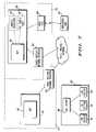
- FIG. 7is a block diagram illustrating operation of an alternate embodiment of a wireless communication in accordance with the present invention.
- the present inventiongenerally provides for enabling multiple users in a dispatch service to contact a call center using a single unique name or number. Multiple users are able to simultaneously dispatch the single generic call center number and communicate with a unique individual at the call center.
- a user, or subscriber unit, when dispatching a callcommunicates initially with the service provider infrastructure. The infrastructure then establishes communication with the call center. The call center determines the identifier of an available end station and the subscriber is subsequently connected to the available end station.
- the present inventionencompasses an infrastructure comprising a call center agent that communicates with the call center.
- the call center agentforwards the identity of the available end station within the call center to the subscriber unit. This enables the subscriber unit to dispatch a call directly to the end station.
- the infrastructurecomprises an address translator that maintains a mapping between the original call center identifier and an available end station identifier within the call center. The address translator performs address translation for the messages in the call session to enable the subscriber unit to communicate with the available end station.
- a dispatch applications processor in the infrastructureperforms the functions of, as described above, the address translator.
- the present inventionfurther encompasses a method for the infrastructure to establish communications between a subscriber unit and a unique end station within the call center.
- the methodcomprises the steps of initiating a dispatch request from the subscriber unit to the system controller using a selected name corresponding to a desired call center, obtaining an identifier corresponding to an available end station within the desired call center and establishing a connection between the subscriber unit and the available end station.
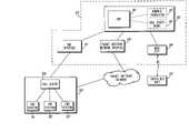
- FIG. 1is a block diagram depiction of a wireless communication system 100 in accordance with a preferred embodiment of the present invention.
- Communication system 100comprises at least one mobile wireless communication or subscriber unit 122 in wireless communication with an infrastructure 103 and a dispatch capable call center system 104 .
- the call center system 104includes a call center 108 and a number of end stations 110 , 110 ′, 110 ′′.
- the end stations 110 , 110 ′, 110 ′′are typically human customer service representatives or voice response terminals that interact electronically with callers using voice.
- the call centeris equipped with dispatch equipment (not shown), such as iDEN Desktop Dispatch units for enabling an IP-connected personal computer to participate in dispatch calls by way of a gateway. It is to be noted that the call center system 104 may be IP network based as well.
- the call center system 104functions as an automated device capable of initiating voice communications to end users.
- a weather tracking station(not shown) initiates a private or group call to a set of participants to provide an update on local weather conditions.
- the source of the callis identified using a single identifier, but the system initiating the communications is capable of initiating multiple calls simultaneously using many virtual end device interfaces.
- the infrastructure 103comprises those elements normally required to support communications within wireless system 100 and may conform to a CDMA, TDMA, GPRS, GSM or other architecture.
- the infrastructure 103comprises an “iDEN” communication system, all components of which are commercially available from “MOTOROLA”, Inc. of Schaumburg, Ill.
- a base site 106preferably comprises an “iDEN” Enhanced Base Transceiver System (EBTS) and a dispatch controller 102 preferably comprises an “iDEN” Dispatch Application Processor (DAP) 105 and either a call center agent 107 or an address translator 120 .
- the mobile wireless communication unit, or subscriber unit (SU) 122preferably comprises an “iDEN” wireless phone.
- call centers and call center agentsmay be used without compromising the scalability of the system.
- reliabilitymay be enhanced by allowing the SU 122 to communicate with multiple call center agents (CCAs).
- CCAscall center agents
- address translatorsmay be used as well to enhance reliability and scalability.
- the infrastructure 103has been limited as shown in FIG. 1 .
- the infrastructure 103also may include a mobile switching center (MSC) for providing the interface between the public switched telephone network (PSTN) and the iDEN network, a Message Mail Service (MMS) for providing text messaging capabilities, such as short message service (SMS) 111 , to subscriber units and Inter-Working Function (IWE) for supporting circuit switched data.
- MSCmobile switching center
- MMSMessage Mail Service
- SMSshort message service
- IWEInter-Working Function
- the infrastructure 103in order to support packet data through a packet switched network, also may include a packet switched network interface 109 such as an iDEN Metro Packet Switch (MPS) and Packet Duplicator.
- MPSiDEN Metro Packet Switch
- Packet DuplicatorPacket Duplicator
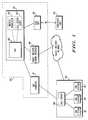
- the dispatch controller 102includes a CCA 107 connected to the DAP 105 .
- the CCA 107which may be a microprocessor based communications device, communicates with the subscriber unit 112 and the call center 108 using packet-data, SMS or dispatch messages.
- the CCA 107functions as an intermediary between the call center 108 , the SU 122 and the DAP 105 .
- the CCA 107receives a message from the SU 122 requesting dispatch to the call center 108 .
- the CCA 107contacts the call center 108 and receives the identifier of an available end station.
- the CCA 107then relays the identifier to the SU 122 , which then dispatches a call to the available end station using the given identifier.
- the CCA 107is capable of communicating with multiple call centers using packet-data, SMS or dispatch messages, as mentioned above.
- the CCA 107has a directory service such as Lightweight Directory Access Protocol (LDAP) that maintains a mapping between call center identifiers as sent by the SU 122 and assigned call center identifiers to enable a specific call center to be contacted based on its identifier.
- LDAPLightweight Directory Access Protocol
- FIG. 3is flow chart illustrating a method for use by the infrastructure 103 .
- the method described in FIG. 3generally is implemented by the infrastructure 103 , the method preferably is carried out by the CCA 107 or by the DAP 105 .
- the functionality illustrated in FIG. 3may be distributed throughout the infrastructure 103 .
- the method illustrated in FIG. 3is implemented as stored software routines that are executed by the platforms on which the software is stored.
- the wireless userselects on the SU 122 the identifier of a particular call center to be contacted.
- the identifier on the SU 122is preferably a memorable character string to help identify the call center being contacted.
- the identifiermay be MOTOROLA or 1-800-FLOWERS or similar such names having a strong identity.
- the userpresses the push to talk (PTT) button on the SU 122 to initiate a private call (step 201 ).
- the SU 122maps the selected call center name to an identifier belonging to the CCA 107 .
- the SU 122initiates a request, with information on the specific call center to be contacted, to the CCA 107 using a packet data, SMS, dispatch system, or other message in step 204 .
- the CCA 107contacts the requested call center 108 through the call center system 104 to obtain an identifier of an available end station 10 , 110 ′, 110 ′′.
- the call center 108allocates an available identifier in step 208 and notifies the CCA 107 of the available identifier in step 208 .
- the call center 108obtains the identity of the available identifier.
- the call center 108is able to obtain the identity of the available identifier from a pool of available identifiers.
- the call center 108obtains information regarding available identifiers from its own database.
- the identifieris preferably reserved for use for a given period of time. If no requests arrive for the reserved identifier before the time period expires, then the identifier is released back to the pool of available identifiers.
- steps 206 and 208may be combined for the purposes of the present invention since it is not always necessary to contact the call center 108 for the ID of an available end station.
- the CCA 107already may have its own database where the information is stored, or the information may reside on a 3 rd database accessible by both the CCA 107 and the call center 108 .
- step 210the CCA 107 forwards the identifier to the SU 122 using one of the messaging systems described above.
- the SU 122then dispatches a private call to the new identifier in step 212 .
- the call center 108upon receiving the call request from the SU 122 , forwards the call request to the particular end station associated with the available identifier, such as the end station 110 ′. Alternatively, instead of forwarding the call request to the end station 110 ′, the call request maybe provided directly to the SU 122 for a direct connection.
- step 216it is determined whether the call to the available identifier has been terminated. If, the call center 108 releases the identifier back into the pool of available identifiers in step 218 . Otherwise, the call continues.
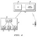
- the dispatch controller 102includes an address translator 120 in communication with the DAP 105 .
- the address translator 120which also maybe a microprocessor based communications device, communicates with the call center 108 using packet-data, dispatch or SMS messaging.
- the address translator 120intercepts a call from the SU 122 requesting dispatch to the call center 108 .
- the address translator 120then contacts the call center 108 using one of the above messaging systems and receives the identifier of an available end station 110 ′.
- the address translator 120is able to obtain available identifier information from a local or remote database populated by the call center 108 .
- the address translater 120switches the identifier of the call center 108 with the identifier of the end station 110 ′, resulting in the SU 122 dispatching a call to the available end station.
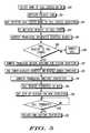
- FIG. 5is a flow chart illustrating a method for use by the infrastructure 103 .
- the method described in FIG. 5generally is implemented by the infrastructure 103 , the method preferably is carried out by the address translater 120 or by the DAP 105 .
- the functionality illustrated in FIG. 5may be distributed throughout the infrastructure 103 .
- the method illustrated in FIG. 5is implemented as stored software routines that are executed by the platforms in which the software is stored.
- the wireless userselects a particular call center on the SU 122 to be contacted, such as MOTOROLA.
- the userpresses the push to talk (PTT) buttton on the SU 122 to initiate a private call in step 301 .
- the SU 122maps the selected call center name to the call center's generic identifier and initiates a dispatch request in step 303 .
- the address translater 120intercepts the call request and determines in step 306 whether the call request is to a call center.
- the address translater 120makes this determination by matching the target address of the call request with a list of identifiers associated with call centers, by matching to a particular ID range allocated for call requests, or by discovering the need to resolve the address to an associated identifier through information retrieved while attempting to route the request.
- the routing informationmay be sourced from a Home Location Register. If the call request is to a call center 108 , the address translater 120 contacts the call center 108 to obtain a new identifier corresponding to an available end station 110 ′ in the call center 108 . The address translater 120 contacts the call center 108 using one of the above messaging systems. Otherwise, if the call request is not to a call center 108 , the call is dispatched in its normal manner in step 308 .
- step 310the call center 108 allocates an identifier and notifies the address translator 120 of the newly allocated identifier. Again, the identifier is available only for a predetermined period of time after which it is released back into a pool of available identifiers if a request for the identifier is not made within the predetermined time.
- step 314the address translator 120 switches the target address on the call request from the generic identifier to the newly allocated available identifier.
- step 316the call request is forwarded onwards to the DAP 105 .
- the DAP 105then sets up a session for the new identifier in step 318 .
- the call requestis received at the call center 108 , it is forwarded to the appropriate end station associated with the available identifier.
- the address translator 120maintains a mapping between the original target address and the newly allocated available identifier and performs address translations for all messages in the current call.
- the DAP 105performs the address translation functions of the address translator 120 as described above, thereby eliminating the need for the address translator 120 . As such, the DAP 105 performs all the functions of the address translator 120 . Thus, additional drawings illustrating Applicant's method are not provided. A particular advantage of such a configuration is the cost savings associated with eliminating the address translator.
- the call center system 104is located remote to the local infrastructure 103 and is connected to a remote infrastructure 103 ′.
- the 5 remote infrastructure 103 ′which includes a DAP 105 ′, communicates with the local DAP 105 over a packet switched interface or IP network.
- a local SU 122is able to dispatch a call to a local call center number as described above, and be connected via the interconnected DAPs 105 , 105 ′ to the call center system 104 , which is located remote to the subscriber unit 122 .
- the 1-800 vanity numbers described aboveare given only by way of example.
- accessing the dispatch call centerrequires the use of a dispatch ID's or other generic identifier instead of a toll-free number.
- the dispatch IDis numerically different from a PSTN number like 1-800-MOTOROLA.
- call lists on subscriber devicesmight obscure the difference.
- an address book entry labeled with the text “1-800-MOTOROLA”may be mapped to a dispatch identification number that is perhaps dynamically assigned.
- a memorable arbitrary text string like “Motorola” or “Mot”is used in the address book and mapped to a dispatch ID.
Landscapes
- Engineering & Computer Science (AREA)
- Databases & Information Systems (AREA)
- Computer Networks & Wireless Communication (AREA)
- Signal Processing (AREA)
- Mobile Radio Communication Systems (AREA)
Abstract
Description
Claims (17)
Priority Applications (1)
| Application Number | Priority Date | Filing Date | Title |
|---|---|---|---|
| US10/167,840US6980821B2 (en) | 2002-06-12 | 2002-06-12 | Call center access in a push to talk based call system |
Applications Claiming Priority (1)
| Application Number | Priority Date | Filing Date | Title |
|---|---|---|---|
| US10/167,840US6980821B2 (en) | 2002-06-12 | 2002-06-12 | Call center access in a push to talk based call system |
Publications (2)
| Publication Number | Publication Date |
|---|---|
| US20030232623A1 US20030232623A1 (en) | 2003-12-18 |
| US6980821B2true US6980821B2 (en) | 2005-12-27 |
Family
ID=29732272
Family Applications (1)
| Application Number | Title | Priority Date | Filing Date |
|---|---|---|---|
| US10/167,840Expired - LifetimeUS6980821B2 (en) | 2002-06-12 | 2002-06-12 | Call center access in a push to talk based call system |
Country Status (1)
| Country | Link |
|---|---|
| US (1) | US6980821B2 (en) |
Cited By (7)
| Publication number | Priority date | Publication date | Assignee | Title |
|---|---|---|---|---|
| US20040032843A1 (en)* | 2002-08-15 | 2004-02-19 | Schaefer Bradley R. | Push-to-talk/cellular networking system |
| US20060115071A1 (en)* | 2004-11-30 | 2006-06-01 | Michael Peters | Method for detecting availability of non-traditional agent |
| US20080008305A1 (en)* | 2004-11-17 | 2008-01-10 | Ralf Neuhaus | Call Distribution in a Direct-Communication Network |
| US20090041226A1 (en)* | 2007-08-08 | 2009-02-12 | Cisco Technology, Inc. | System and Method for Using the Reliability of an Agent's Connectivity as an Agent Selection Criteria |
| US20090141174A1 (en)* | 2007-11-30 | 2009-06-04 | Sony Corporation | System and method for presenting guide data on a remote control |
| US7574227B1 (en)* | 2004-09-22 | 2009-08-11 | Nextel Communcations Inc. | System and method for dispatch calling using personal telephone numbers |
| US8126017B1 (en)* | 2004-05-21 | 2012-02-28 | At&T Intellectual Property Ii, L.P. | Method for address translation in telecommunication features |
Families Citing this family (13)
| Publication number | Priority date | Publication date | Assignee | Title |
|---|---|---|---|---|
| US7403607B2 (en)* | 2003-12-23 | 2008-07-22 | Nortel Networks | Directing contacts between an end user and a contact center agent |
| KR100652650B1 (en)* | 2004-07-28 | 2006-12-06 | 엘지전자 주식회사 | PITITY SERVICE SYSTEM AND METHOD FOR SYNCHRONIZATION IN SERVICE SHARED |
| US8923797B2 (en)* | 2007-07-31 | 2014-12-30 | General Motors Llc | Method of establishing a communications connection from a deactivated telematics unit on a motor vehicle |
| US8561118B2 (en) | 2008-08-05 | 2013-10-15 | Mediafriends, Inc. | Apparatus and methods for TV social applications |
| US20120221962A1 (en) | 2008-08-05 | 2012-08-30 | Eugene Lee Lew | Social messaging hub system |
| US9356907B2 (en) | 2008-08-05 | 2016-05-31 | HeyWire, Inc. | Messaging system having multiple number, dual mode phone support |
| US12238246B2 (en)* | 2008-08-05 | 2025-02-25 | Salesforce, Inc. | Call center mobile messaging |
| US11172067B1 (en)* | 2008-08-05 | 2021-11-09 | HeyWire, Inc. | Call center mobile messaging |
| US10064024B2 (en) | 2014-02-14 | 2018-08-28 | HeyWire, Inc. | Cloud hosted multimedia file handling on mobile devices |
| US9256726B2 (en)* | 2014-02-19 | 2016-02-09 | Avaya Inc. | Call center customer service kiosk |
| US10360309B2 (en) | 2015-04-30 | 2019-07-23 | Salesforce.Com, Inc. | Call center SMS-MMS language router |
| WO2018013511A1 (en) | 2016-07-11 | 2018-01-18 | Salesforce.Com, Inc. | System and method to use a mobile number in conjunction with a non-telephony internet connected device |
| CN113269476B (en)* | 2021-07-01 | 2024-06-04 | 中电智恒信息科技服务有限公司 | Scheduling method for intelligent cloud call center to call multi-manufacturer AI (advanced technology attachment) capability |
Citations (10)
| Publication number | Priority date | Publication date | Assignee | Title |
|---|---|---|---|---|
| US5841854A (en)* | 1994-02-16 | 1998-11-24 | Priority Call Management, Inc. | Wireless telephone integration system and method for call centers and workgroups |
| US6314177B1 (en)* | 1998-12-22 | 2001-11-06 | Nortel Networks Limited | Communications handling center and communications forwarding method using agent attributes |
| US6473505B1 (en)* | 1999-04-27 | 2002-10-29 | Sprint Communications Company L.P. | Call processing system for handling calls to a call center |
| US20030083086A1 (en)* | 2001-11-01 | 2003-05-01 | Hannu Toyryla | Method for creating a dynamic talk group |
| US20030104827A1 (en)* | 2001-11-30 | 2003-06-05 | Brian Moran | Rerouting/reformating wireless messages for cross connectivity between service providers |
| US20030144018A1 (en)* | 1999-01-29 | 2003-07-31 | Siemens Transportation Systems, Inc. | Multiple channel communications system |
| US20030211859A1 (en)* | 2002-05-08 | 2003-11-13 | Chen An Mei | Method and apparatus for supporting application-layer media multicasting |
| US20030223571A1 (en)* | 2002-05-28 | 2003-12-04 | Dezonno Anthony J. | Web callback through multimedia devices |
| US6744858B1 (en)* | 2001-01-26 | 2004-06-01 | Telcontrol, Inc. | System and method for supporting multiple call centers |
| US6766009B2 (en)* | 2002-03-07 | 2004-07-20 | Newstep Networks Inc. | Method and system for correlating telephone calls with information delivery |
- 2002
- 2002-06-12USUS10/167,840patent/US6980821B2/ennot_activeExpired - Lifetime
Patent Citations (10)
| Publication number | Priority date | Publication date | Assignee | Title |
|---|---|---|---|---|
| US5841854A (en)* | 1994-02-16 | 1998-11-24 | Priority Call Management, Inc. | Wireless telephone integration system and method for call centers and workgroups |
| US6314177B1 (en)* | 1998-12-22 | 2001-11-06 | Nortel Networks Limited | Communications handling center and communications forwarding method using agent attributes |
| US20030144018A1 (en)* | 1999-01-29 | 2003-07-31 | Siemens Transportation Systems, Inc. | Multiple channel communications system |
| US6473505B1 (en)* | 1999-04-27 | 2002-10-29 | Sprint Communications Company L.P. | Call processing system for handling calls to a call center |
| US6744858B1 (en)* | 2001-01-26 | 2004-06-01 | Telcontrol, Inc. | System and method for supporting multiple call centers |
| US20030083086A1 (en)* | 2001-11-01 | 2003-05-01 | Hannu Toyryla | Method for creating a dynamic talk group |
| US20030104827A1 (en)* | 2001-11-30 | 2003-06-05 | Brian Moran | Rerouting/reformating wireless messages for cross connectivity between service providers |
| US6766009B2 (en)* | 2002-03-07 | 2004-07-20 | Newstep Networks Inc. | Method and system for correlating telephone calls with information delivery |
| US20030211859A1 (en)* | 2002-05-08 | 2003-11-13 | Chen An Mei | Method and apparatus for supporting application-layer media multicasting |
| US20030223571A1 (en)* | 2002-05-28 | 2003-12-04 | Dezonno Anthony J. | Web callback through multimedia devices |
Cited By (10)
| Publication number | Priority date | Publication date | Assignee | Title |
|---|---|---|---|---|
| US20040032843A1 (en)* | 2002-08-15 | 2004-02-19 | Schaefer Bradley R. | Push-to-talk/cellular networking system |
| US8126017B1 (en)* | 2004-05-21 | 2012-02-28 | At&T Intellectual Property Ii, L.P. | Method for address translation in telecommunication features |
| US7574227B1 (en)* | 2004-09-22 | 2009-08-11 | Nextel Communcations Inc. | System and method for dispatch calling using personal telephone numbers |
| US20080008305A1 (en)* | 2004-11-17 | 2008-01-10 | Ralf Neuhaus | Call Distribution in a Direct-Communication Network |
| US8514840B2 (en)* | 2004-11-17 | 2013-08-20 | Siemens Enterprise Communications Gmbh & Co. Kg | Call distribution in a direct-communication network |
| US20060115071A1 (en)* | 2004-11-30 | 2006-06-01 | Michael Peters | Method for detecting availability of non-traditional agent |
| US7864945B2 (en)* | 2004-11-30 | 2011-01-04 | Aspect Software, Inc. | Method for detecting availability of non-traditional agent |
| US20090041226A1 (en)* | 2007-08-08 | 2009-02-12 | Cisco Technology, Inc. | System and Method for Using the Reliability of an Agent's Connectivity as an Agent Selection Criteria |
| US20090141174A1 (en)* | 2007-11-30 | 2009-06-04 | Sony Corporation | System and method for presenting guide data on a remote control |
| US8792058B2 (en) | 2007-11-30 | 2014-07-29 | Sony Corporation | System and method for presenting guide data on a remote control |
Also Published As
| Publication number | Publication date |
|---|---|
| US20030232623A1 (en) | 2003-12-18 |
Similar Documents
| Publication | Publication Date | Title |
|---|---|---|
| US6980821B2 (en) | Call center access in a push to talk based call system | |
| CA2495093C (en) | Providing routing information in a communication system | |
| US6882856B1 (en) | Method for dynamically configuring group calls in a radio system | |
| US6138011A (en) | Method and apparatus for providing dispatch service to an existing telephone network | |
| EP1155579B1 (en) | A system selectively delivering calls to mobile devices | |
| US6026296A (en) | Apparatus for providing dispatch service to an existing telephone network | |
| JP3453138B2 (en) | Personal paging method | |
| JP3402612B2 (en) | Method and apparatus for dynamically assigning addresses to wireless communication stations | |
| US20070105531A1 (en) | Dynamic Processing of Virtual Identities for Mobile Communications Devices | |
| US8340040B2 (en) | System and method for providing mobile based services for hotel PBX | |
| US6442396B1 (en) | Method of processing group calls within a wireless communications network | |
| JPH11510991A (en) | Method and apparatus for notifying a remote device of a feature originating call | |
| CN1622573A (en) | System for providing interoperability of a proprietary enterprise communication network with a cellular communication network | |
| US6965594B2 (en) | Internet assisted mobile calling | |
| US20040137923A1 (en) | Short text messaging-based incoming call termination control | |
| JP2001157241A (en) | Method for using substitute message for retrieval of voice mail by way of cooperative calling | |
| US7403516B2 (en) | Enabling packet switched calls to a wireless telephone user | |
| US8351972B1 (en) | System and method for addressing dispatch stations | |
| KR100684941B1 (en) | System and method for providing presence service in premises wireless communication network | |
| US7509137B2 (en) | Method and system for address translation and aliasing to efficiently utilize UFMI address space | |
| US7813737B1 (en) | Integrated digital enhanced network migrated subscriber mapping | |
| JP3336938B2 (en) | Mobile phone system | |
| KR100760705B1 (en) | Method and system for providing conference call service to multiple user terminals | |
| EP1327372B1 (en) | A method and a system for signalling between a digital mobile communication system and a data communication network | |
| KR100234833B1 (en) | How to Transfer a Voice Mail Service in a Failed Transfer |
Legal Events
| Date | Code | Title | Description |
|---|---|---|---|
| AS | Assignment | Owner name:MOTOROLA, INC., ILLINOIS Free format text:ASSIGNMENT OF ASSIGNORS INTEREST;ASSIGNORS:BALASURIYA, SENAKA;COX, GREGORY W.;UPP, STEVEN;REEL/FRAME:013002/0740;SIGNING DATES FROM 20020529 TO 20020603 | |
| AS | Assignment | Owner name:MOTOROLA, INC., ILLINOIS Free format text:RE-RECORD TO ADD OMITTED CONVEYING PARTY'S NAME, PREVIOUSLY RECORDED AT REEL 013002, FRAME 0740.;ASSIGNORS:BALASURIYA, SENAKA;UPP, STEVEN;COX, GREGORY W.;AND OTHERS;REEL/FRAME:014927/0436;SIGNING DATES FROM 20020522 TO 20020603 | |
| STCF | Information on status: patent grant | Free format text:PATENTED CASE | |
| FPAY | Fee payment | Year of fee payment:4 | |
| AS | Assignment | Owner name:MOTOROLA MOBILITY, INC, ILLINOIS Free format text:ASSIGNMENT OF ASSIGNORS INTEREST;ASSIGNOR:MOTOROLA, INC;REEL/FRAME:025673/0558 Effective date:20100731 | |
| AS | Assignment | Owner name:MOTOROLA MOBILITY LLC, ILLINOIS Free format text:CHANGE OF NAME;ASSIGNOR:MOTOROLA MOBILITY, INC.;REEL/FRAME:029216/0282 Effective date:20120622 | |
| FPAY | Fee payment | Year of fee payment:8 | |
| AS | Assignment | Owner name:GOOGLE TECHNOLOGY HOLDINGS LLC, CALIFORNIA Free format text:ASSIGNMENT OF ASSIGNORS INTEREST;ASSIGNOR:MOTOROLA MOBILITY LLC;REEL/FRAME:034311/0001 Effective date:20141028 | |
| FPAY | Fee payment | Year of fee payment:12 |