US6980613B2 - Ultra-wideband correlating receiver - Google Patents
Ultra-wideband correlating receiverDownload PDFInfo
- Publication number
- US6980613B2 US6980613B2US10/718,984US71898403AUS6980613B2US 6980613 B2US6980613 B2US 6980613B2US 71898403 AUS71898403 AUS 71898403AUS 6980613 B2US6980613 B2US 6980613B2
- Authority
- US
- United States
- Prior art keywords
- signal
- pulse
- uwb
- ultra
- receiver
- Prior art date
- Legal status (The legal status is an assumption and is not a legal conclusion. Google has not performed a legal analysis and makes no representation as to the accuracy of the status listed.)
- Expired - Lifetime, expires
Links
- 238000004891communicationMethods0.000abstractdescription24
- 238000000034methodMethods0.000description39
- 238000001208nuclear magnetic resonance pulse sequenceMethods0.000description23
- 230000002596correlated effectEffects0.000description20
- 230000010363phase shiftEffects0.000description10
- 238000013139quantizationMethods0.000description9
- 230000001427coherent effectEffects0.000description8
- 230000005540biological transmissionEffects0.000description7
- 238000005070samplingMethods0.000description6
- 238000001514detection methodMethods0.000description5
- 238000005516engineering processMethods0.000description5
- 230000001360synchronised effectEffects0.000description4
- 230000003111delayed effectEffects0.000description3
- 238000012937correctionMethods0.000description2
- 230000000875corresponding effectEffects0.000description2
- 230000009977dual effectEffects0.000description2
- 239000000835fiberSubstances0.000description2
- 238000001914filtrationMethods0.000description2
- 238000012545processingMethods0.000description2
- 238000001228spectrumMethods0.000description2
- 102100036601Aggrecan core proteinHuman genes0.000description1
- 101000831175Homo sapiens Mitochondrial import inner membrane translocase subunit TIM16Proteins0.000description1
- 102100024285Mitochondrial import inner membrane translocase subunit TIM16Human genes0.000description1
- 108091006419SLC25A12Proteins0.000description1
- 108091006418SLC25A13Proteins0.000description1
- 230000003321amplificationEffects0.000description1
- 238000013459approachMethods0.000description1
- 230000002238attenuated effectEffects0.000description1
- 239000003990capacitorSubstances0.000description1
- 239000000969carrierSubstances0.000description1
- 230000001413cellular effectEffects0.000description1
- 238000006243chemical reactionMethods0.000description1
- 238000002591computed tomographyMethods0.000description1
- 230000010354integrationEffects0.000description1
- 230000002452interceptive effectEffects0.000description1
- 238000003199nucleic acid amplification methodMethods0.000description1
- 239000013307optical fiberSubstances0.000description1
- 238000012552reviewMethods0.000description1
- 239000003381stabilizerSubstances0.000description1
Images


Classifications
- H—ELECTRICITY
- H04—ELECTRIC COMMUNICATION TECHNIQUE
- H04B—TRANSMISSION
- H04B1/00—Details of transmission systems, not covered by a single one of groups H04B3/00 - H04B13/00; Details of transmission systems not characterised by the medium used for transmission
- H04B1/69—Spread spectrum techniques
- H04B1/7163—Spread spectrum techniques using impulse radio
- H04B1/71637—Receiver aspects
- H—ELECTRICITY
- H04—ELECTRIC COMMUNICATION TECHNIQUE
- H04B—TRANSMISSION
- H04B1/00—Details of transmission systems, not covered by a single one of groups H04B3/00 - H04B13/00; Details of transmission systems not characterised by the medium used for transmission
- H04B1/69—Spread spectrum techniques
- H04B1/7163—Spread spectrum techniques using impulse radio
- H04B1/7183—Synchronisation
Definitions
- the present inventiongenerally relates to ultra-wideband communications. More particularly, the invention concerns an apparatus for receiving and demodulating ultra-wideband electromagnetic pulses for wire and wireless communications.
- the Information Ageis upon us. Access to vast quantities of information through a variety of different communication systems are changing the way people work, entertain themselves, and communicate with each other. For example, as a result of increased telecommunications competition mapped out by Congress in the 1996 Telecommunications Reform Act, traditional cable television program providers have evolved into full-service providers of advanced video, voice and data services for homes and businesses. A number of competing cable companies now offer cable systems that deliver all of the just-described services via a single broadband network.
- bandwidthis the amount of data transmitted or received per unit time. More bandwidth has become increasingly important, as the size of data transmissions has continually grown.
- Applicationssuch as movies-on-demand and video teleconferencing demand high data transmission rates.
- Another exampleis interactive video in homes and offices.
- traffic across the Internetcontinues to increase, and with the introduction of new applications, such as the convergence of voice and Internet data, traffic will only increase at a faster rate. Consequently, carriers and service providers are overhauling the entire network infrastructure—including switches, routers, backbone, and the last mile (i.e., the local loop)—in an effort to provide more bandwidth.
- the present inventionprovides an apparatus for receiving and demodulating an ultra-wideband signal.
- the receivermay be configured to work in conjunction with wireless or wire communications mediums, whether the medium is twisted-pair wire, coaxial cable, fiber optic cable, or other types of wire media.
- One feature of the present inventionis it provides a receiver with demodulation capability of amplitude-, phase-, and timing-based modulation schemes. Another feature of the present invention is that it uses only a single correlator to detect and demodulate ultra-wideband pulses. Another feature of the present invention provides a receiver structured to operate in a multi-path environment.
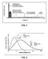
- FIG. 1is an illustration of different communication methods
- FIG. 2is an illustration of two ultra-wideband pulses
- FIG. 3is an illustration of a conventional non-coherent receiver architecture
- FIG. 4is an illustration of two conventional coherent receiver architectures
- FIG. 5is an illustration of one embodiment of the present invention.
- FIG. 6is an illustration of one embodiment of a radio frequency front-end and a correlator as shown in FIG. 5 ;
- FIG. 7is an illustration of the output of different receivers in the presence of white noise and multi-path conditions
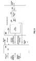
- FIG. 8is an illustration of one embodiment of the pulse level quantization block, pulse amplifier and energy estimator as shown in FIG. 5 ;
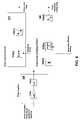
- FIG. 9is an illustration of one embodiment of the Digital Signal Processor (DSP) and the template generator as shown in FIG. 5 ;
- DSPDigital Signal Processor
- FIG. 10is an illustration of an ultra-wideband pulse signal coarse acquisition process, fine acquisition method, and pulse sampling method
- FIG. 11is an illustration of the ultra-wideband pulse acquisition process in the presence of multi-path interference and white noise
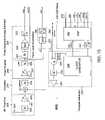
- FIG. 12is an illustration of an ultra-wideband pulse receiver according to one embodiment of the present invention.
- FIG. 13illustrates a method for receiving ultra-wideband signals according to one embodiment of the present invention
- FIG. 14illustrates a system for receiving ultra-wideband signals according to one embodiment of the present invention
- FIG. 15illustrates another embodiment of a correlating receiver structured to receive various data modulation schemes
- FIG. 16illustrates another embodiment of a correlating receiver structured to operate in a multi-path environment.
- the present inventionprovides a method of receiving and demodulating a plurality of electromagnetic ultra-wideband (UWB) pulses.
- the pulsescan be transmitted and received wirelessly, or through any wire medium, whether the medium is twisted-pair wire, coaxial cable, fiber optic cable, hybrid fiber-coax, or other type of wire media.
- ultra-wideband (UWB) communication technologyemploys pulses of electromagnetic energy that are emitted at, for example, nanosecond or picosecond intervals (generally tens of picoseconds to a few nanoseconds in duration). For this reason, ultra-wideband is often called “impulse radio.” That is, the UWB pulses are transmitted without modulation onto a sine wave carrier frequency, in contrast with conventional radio frequency technology as described above.
- a UWB pulseis a single electromagnetic burst of energy. That is, a UWB pulse may be a single positive burst of electromagnetic energy, a single negative burst of electromagnetic energy or a single burst of electromagnetic energy with a predefined phase.
- UWBcan be achieved by mixing baseband pulses with a carrier wave that controls a center frequency of a resulting UWB signal.
- Ultra-widebandgenerally requires neither an assigned frequency nor a power amplifier.
- FIG. 1An example of a conventional radio frequency technology is illustrated in FIG. 1 .
- IEEE 802.11aa wireless local area network (LAN) protocol, transmits radio frequency signals at a 5 GHz center frequency, with a radio frequency spread of about 5 MHz.
- a UWB pulsemay have a 2.0 GHz center frequency, with a frequency spread of approximately 4 GHz, as shown in FIG. 2 , which illustrates two typical UWB pulses.
- FIG. 2illustrates that the shorter the UWB pulse in time, the broader the spread of its frequency spectrum. This is because bandwidth is inversely proportional to the time duration of the pulse.
- a 600-picosecond UWB pulsecan have about a 1.8 GHz center frequency, with a frequency spread of approximately 1.6 GHz and a 300-picosecond UWB pulse can have about a 3 GHz center frequency, with a frequency spread of approximately 3.2 GHz.
- UWB pulsesgenerally do not operate within a specific frequency, as shown in FIG. 1 . Because UWB pulses are spread across an extremely wide frequency range, UWB communication systems allow communications at very high data rates, such as 100 megabits per second or greater.
- a UWB pulseis spread across an extremely wide frequency range, the power sampled at a single, or specific frequency is very low.
- a UWB one-watt pulse of one nano-second durationspreads the one-watt over the entire frequency occupied by the UWB pulse.
- the UWB pulse power presentis one nano-watt (for a frequency band of 1 GHz). This is calculated by dividing the power of the pulse (i.e., 1 watt) by the frequency band (i.e., 1 billion Hertz).
- UWB pulsesare transmitted at relatively low power (when sampled at a single, or specific frequency), for example, at less than ⁇ 30 power decibels to ⁇ 60 power decibels, which reduces interference with conventional radio frequencies.
- UWB pulsestransmitted through many wire media typically do not interfere with wireless radio frequency transmissions. Therefore, the power (sampled at a single frequency) of UWB pulses transmitted though wire media may range from about +30 dBm to about ⁇ 140 dBm.
- the present inventionmay be employed in any type of network, be it wireless, wire, or a mix of wire media and wireless components. That is, a network may use both wire media, such as coaxial cable, and wireless devices, such as satellites, or cellular antennas.
- a networkis a group of points or nodes connected by communication paths. The communication paths may be use wires or be wireless.
- a network as defined hereinmay interconnect with other networks and contain sub-networks.
- a network as defined hereinmay be characterized in terms of a spatial distance, for example, such as a local area network (LAN), a personal area network (PAN), a metropolitan area network (MAN), a wide area network (WAN), and a wireless personal area network (WPAN), among others.
- LANlocal area network
- PANpersonal area network
- MANmetropolitan area network
- WANwide area network
- WPANwireless personal area network
- a network as defined hereinmay also be characterized by the type of data transmission technology in use on it, for example, a Transmission Control Protocol/Internet Protocol (TCP/IP) network, and a Systems Network Architecture network, among others.
- a network as defined hereinmay also be characterized by whether it carries voice signals, data signals, or both.
- a network as defined hereinmay also be characterized by users of the network, such as, for example, users of a public switched telephone network (PSTN) other type of public networks, and private networks (such as within a single room or home), among others.
- PSTNpublic switched telephone network
- a network as defined hereinmay also be characterized by the usual nature of its connections, for example, a dial-up network, a switched network, a dedicated network, and a non-switched network, among others.
- a network as defined hereinmay also be characterized by the types of physical links that it employs, for example, optical fiber, coaxial cable, a mix of both, unshielded twisted pair, and shielded
- the present inventionmay also be employed in any type of wireless network, such as a wireless PAN, LAN, MAN, or WAN.
- the present inventionmay be implemented in a “carrier free” architecture, which does not require the use of high frequency carrier generation hardware, carrier modulation hardware, stabilizers, frequency and phase discrimination hardware or other devices employed in conventional frequency domain communication systems.
- One method practiced by the present inventioninvolves modulation and demodulation of data by employing Differentially Phase Shift Keying (DPSK), or Phase Shift Keying (PSK) for an ultra-wideband receiver.
- An incoming signalmay be a plurality of ultra-wideband (UWB) pulses wherein each of the pulses includes data encoded within a phase of the pulse.
- One method herein describedinitially estimates timing of the incoming signal with the use of a correlator and an energy estimator.
- the correlatorproduces a UWB pulse that matches in frequency and phase a UWB pulse generated by a UWB transmitter.
- the lower mixing (or multiplication) product that represents the UWB pulseis forwarded to a UWB pulse envelope matched filter.
- Additional components of the correlation receivermay include a multiplicative mixer, amplifiers, and band-pass and low-pass filters.
- the incoming signalmay be correlated with a local template signal then sent to the energy estimator.
- the energy estimatormay include an absolute value detector such as a rectifier or a square law detector that outputs the square of the incoming signal.
- the function of the absolute value detectoris to provide a rectified pulse to an integrator.
- the integratorsums the UWB pulse, or signal across a finite time period and provides its output as a coarse timing signal to an analog to digital converter (ADC) and then to a digital signal processor (DSP).
- ADCanalog to digital converter
- DSPdigital signal processor
- This summed signalgives the receiver a coarse timing estimate of the incoming signal or UWB pulse window.
- This coarse signalwhich in one embodiment is within one period of the UWB pulse, is appropriate for fast acquisition of UWB pulse position.
- the energy estimatorprovides a reference signal for accurate phase/frequency tuning of a UWB pulse template to an incoming UWB pulse, or signal.
- a number of receiver architecturesare known in the art of ultra-wideband communications. These conventional architectures can be classified into two basic groups: coherent and non-coherent.
- One usual approach, as illustrated in FIG. 3 , to non-coherent detection and demodulationinvolves the use of envelope detectors 12 to provide an output signal 40 that is representative of an incoming signal 10 .
- the incoming signal 10arrives at an envelope detector 12 that includes a resistor R 1 and a Diode D 1 .
- a negative part of the incoming signal 10is suppressed by the diode D 1 and a half wave rectified signal 20 is developed across the resistor R 1 .
- the half-wave rectified signal 20contains high frequency components that are attenuated by a low-pass filter 14 .
- a resultant low frequency signal 30is representative of the input signal but has a direct current (DC) offset.
- a capacitor C 1blocks the DC component of the signal 30 and the output signal 40 is developed across a resistor R 2 .
- Non-coherent architectureshave been used in the field of communications to receive and demodulate both amplitude-related signal modulation schemes, such as Amplitude Modulation (AM), dual sideband modulation, single sideband modulation, vestigial sideband modulation, as well as angle-related modulation schemes such as Frequency Modulation (FM) and Phase Modulation (PM).
- AMAmplitude Modulation
- FMFrequency Modulation
- PMPhase Modulation
- a correlating chainis a process for performing one or more functions.
- a continuous time correlating chainincludes an analog correlator that includes a product (or mixer) followed by an integrator.
- An incoming signalis multiplied by a locally generated signal and transmitted to an integrator that integrates and dumps the signal over a period of time.
- One correlating chainis used to provide a coarse timing estimate of a pulse.
- the coarse timing estimateis used to dither the frequency and phase of a locally generated signal.
- a second correlating chainis used as a data detector to lock-in on a precise timing of the signal and a peak of the pulse.
- an ultra-wideband (UWB) receiveruses only a single correlator to estimate the coarse timing and also updates a locally generated signal for data detection.
- the correlation receivermay include an absolute value detector that receives output from a pulse amplifier and delivers inputs into an integrator. By using an absolute value detector in such a manner, this allows the integrator to integrate and dump over a wider range of time.
- the absolute value detectorprovides twice as much energy as typically transmitted to the integrator by adding a negative portion of the correlated signal (i.e., taking the absolute value of the signal) to the positive portion of the correlated signal. This is because conventional UWB receivers use a diode which prevents the negative portion of a correlated signal from being transmitted to the integrator. Thus, only half of a signal is used to obtain the coarse timing signal.
- a coherent detectoris commonly used.
- a conventional coherent receiver architecture 60is illustrated in FIG. 4 .
- An incoming signalis multiplied by a locally generated signal cos( ⁇ c t) using a mixer 50 ( a ).
- the locally generated signalis at the same frequency ⁇ c as a carrier of the incoming signal.
- the product of the incoming signal and the locally generated signalwill have two components. Because the locally generated signal is at a carrier frequency, the first signal component will be low frequency or close to DC.
- the second signal componentis at twice the carrier frequency.
- a low-pass filter 52may be used to attenuate a high frequency component of the output signal.
- a voltage controlled oscillator (VCO) 62generates a local signal which is mixed with an incoming signal by a mixer 50 ( b ) to produce a first mixed signal.
- a copy of the local signalmay be phase delayed by ⁇ /2 and mixed with the incoming signal by mixer 50 ( c ) to produce a second mixed signal.
- the mixed signalsare then mixed to produce an error signal, which may then be transmitted through a low-pass filter 64 ( a ), 64 ( b ), 64 ( c ) to control the VCO 62 .
- the first mixed signalis taken as an output.
- a number of correlator designs, or architecturesare used in ultra-wideband communications.
- two correlatorsare used.
- Each correlatorincludes a mixer and an integrator.
- a local template signalis generated and delayed with a delay element to produce a second template signal.
- the first template signalis correlated with an incoming signal.
- the incoming signalis additionally correlated with the delayed template signal.
- Either the first or second correlatorprovides a feedback signal to the template generator.
- FIG. 5illustrates an ultra-wideband correlating receiver constructed according to one embodiment of the present invention.
- an incoming signalis received at a radio frequency (RF) front end 80 .
- the RF front end 80may include an antenna 80 ( a ), a, at least one filter 80 ( b ), and at least one amplifier (AMP) 80 ( c ).
- the filter 80 ( b )may be a band-pass filter (BPF).
- the amplifier 80 ( c )may be a low noise amplifier with or without gain control (GC) capabilities.
- GCgain control
- the correlator 90may include a mixer 90 ( a ) and a UWB pulse matched filter (MPEF) 90 ( b ). Additionally, there may be an optional amplifier in the correlator (not shown). The optional amplifier may include gain controlled capabilities.
- the mixer 50 ( d )multiplies the incoming signal by a locally generated template signal. The product of these signals has a high frequency component and a low frequency component. The high frequency component and noise is filtered by the UWB pulse matched filter 90 ( b ).
- FIG. 7illustrates the output from a square law detector receiver (A), a direct conversion receiver (B), and a UWB correlation receiver (C), constructed according to one embodiment of the present invention.
- a cross correlated ultra-wideband (UWB) pulse signal from the correlator 90may be forwarded to a pulse amplifier 100 for further amplification in amplifier 100 ( a ).
- the pulse amplifier 100may include a low-pass harmonic filter 100 ( b ).
- the pulse sequence energy estimator 120may be used to provide a correlated pulse energy level in a coarse/fine tuning process.
- the pulse sequence energy estimator 120 signalmay be transmitted to a digital signal processor (DSP) 130 (shown in FIG. 5 ) that provides a correlation aperture window signal, and/or a fine tuning signal for adjusting to a UWB pulse phase/frequency, and also executes a coarse UWB pulse positioning/fine tuning algorithm.
- DSPdigital signal processor
- the pulse sequence energy estimator 120may include an absolute value detector 120 ( a ) that converts a negative portion of a correlated signal into a positive portion.
- the absolute value detector 120 ( a )may include a square law detector.
- the pulse sequence energy estimator 120may additionally include an integrate and dump function 120 ( b ).
- the integrate and dump function 120 ( b )sums energy over a fixed time period and outputs a signal corresponding to the amount of energy summed over that time period.
- the energy estimator 120may further include an analog-to-digital (A/D) converter 120 ( d ).
- A/Danalog-to-digital
- the A/D converter 120 ( d )may provide a correlated pulse energy level to the DSP 130 .
- One purpose of the correlated pulse energy level window signalis to provide a reference related to the degree of correlation between the template and an incoming pulse to the DSP 130 .
- the DSP 130then makes a decision relating to window aperture positioning and phase/frequency correction.
- the pulse level quantization block 110may include a sample-and-hold function 110 ( a ) and an A/D function 110 ( b ).
- the correlated signalmay be sampled by the sample-and-hold function 110 ( a ) and converted to a digital signal by the A/D function 110 ( b ).
- the correlated signalmay carry data that represents polarity or pulse position in a data modulation symbol slot by its presence or absence in a given symbol slot location.
- the A/D function 110 ( b )may be multi-level wherein it is capable of producing one, or more, bit resolution from a sample.
- the A/D function 110 ( b )is a 4-bit per sample resolution.
- the DSP 130receives the data signal or digitized pulse level from a pulse level quantization block 110 and the signal that is proportional to pulse sequence energy content from the pulse sequence energy estimator 120 .
- an integration window timing pulseis provided by the DSP 130 as well, and it is forwarded to an integrate and dump block 120 ( b ).
- the DSP 130may comprise one or more of: a Digital Signal Processor (DSP); a general-purpose computer processor; or a finite state machine.
- the DSP 130may further process and format the received data.
- the DSP 130may generate two output signals to the template generator 140 . Both outputs may be based on an pulse sequence energy data input which represent output from the pulse sequence energy estimator 120 .
- the coarse pulse acquisition signalprovides a correlation window (Tw) (shown in FIG. 10A ) and its position within a symbol slot (Ts). In a preferred embodiment, accuracy of positioning may be defined within one period of an ultra-wideband pulse.
- the correlation window Twmay be shifted within the symbol slot Ts until the pulse sequence energy (E 0-n ) data exhibits its highest level, as shown in FIG. 10 A( 1 ). Pulse sequence energy (E 0-n ) data is provided by A/D converter 120 ( d ) of pulse energy estimator 120 .
- a fine pulse acquisition signalmay vary the frequency/phase of a reference oscillator (not shown) in clock generator 140 ( a ) of template generator 140 , until the energy data signal exhibits its new highest level that corresponds to a minimal phase difference ⁇ (as shown in FIG. 10B ), with a 0 or 180 degree offset between a signal template and a pulse.
- DSP 130provides a sampling clock to the pulse level quantization block 110 .
- This sampling clockis phased in such way that its sampling edge falls in the middle of an incoming ultra-wideband (UWB) pulse. This may be achieved by delaying a sampling edge by Tp (as shown in FIG. 10C ) relative to a synchronized correlation window aperture. Multiple sampling within the UWB pulse duration is also possible in order to achieve a better signal-to-noise ratio.
- UWBultra-wideband
- a digitized pulseis then forwarded to the DSP 130 as pulse level data input.
- the datamay be provided to a user in a number of different formats, such as, USB, PCI, serial synchronous, serial asynchronous, etc.
- a standard clock inputmay accept clock output from a clock generator 140 ( a ) that is generated from a common reference oscillator, causing all timing events to appear synchronous.
- the template generator 140may include a signal generator 140 ( a ) such as a phase locked loop (PLL), a gating function 140 ( b ), a harmonic low pass filter 140 ( c ) and an optional amplifier 140 ( d ).
- the clock generator 140 ( a )may include components normally present in a frequency synthesizers such as a PLL, a voltage controlled oscillator (VCO), filters, amplifiers, passive or active multipliers, digital dividers, and counters, to name a few.
- the clock generator 140 ( a )generates a signal whose frequency is equal or close to a received ultra-wideband pulse frequency. This frequency is forwarded to the AND gate function 140 ( b ).
- the clock generator 140 ( a )provides a lock to DSP 130 that assures timing synchronicity.
- the clock frequency/phasemay be controlled by the DSP 130 by means of a tunable frequency reference oscillator that is part of the clock generator 140 ( a ).
- a “loop”comprising the correlator 90 , pulse amplifier 100 , pulse sequence energy estimator 120 , DSP 130 and template generator 140 are shown.
- the gating function 120 ( b )allows a signal whose frequency is equal or close to a received ultra-wideband pulse to pass when the DSP 130 sends a template window with a duration of Tw.
- the DSP 130determines the coarse timing of an incoming signal it begins to dither the phase/frequency first and second signals to achieve the optimum correlation from the correlator 90 .
- Optimum correlation valuesare achieved when the frequency of the template signal best matches the frequency/phase of the incoming ultra-wideband pulse.
- Low-pass filter 140 ( c )( FIG. 9 ) serves as a harmonic suppressor that eliminates the high frequency content from the square wave that is received from gate 140 ( b ) and thus provides a sine wave to the input of the optional amplifier 140 ( d ).
- Minimum correlation valuesthen indicate a phase shift in the data relative to the template, and maximum values indicate no phase shift between the template signal and the incoming signal.
- FIG. 11is an illustration of the ultra-wideband pulse acquisition process in the presence of multi-path and white noise. Specifically, three different stages of ultra-wideband pulse acquisition are illustrated: A) when no ultra-wideband pulse is detected by the correlating receiver constructed according to one embodiment of the present invention; B) when a weak ultra-wideband pulse is detected by the correlating receiver constructed according to one embodiment of the present invention; and C) when a strong ultra-wideband pulse is detected by the correlating receiver constructed according to one embodiment of the present invention.
- FIG. 12illustrates an ultra-wideband correlator receiver 400 that uses binary phase shift keying according to one embodiment of the present invention.
- the receiver 400may include an RF front end 200 .
- the RF front end 200may include an antenna 201 , band-pass filter 202 , and low noise amplifier 203 .
- the band-pass filter 202filters signals having a frequency in a range of 3–5 GHz and the amplifier 208 is an automatic gain control (AGC) amplifier.
- AGCautomatic gain control
- the RF front end 200may be in communication with a correlator 210 .
- the correlator 210may include a mixer 211 , and an ultra-wideband pulse envelope matched filter 212 .
- Pulse amplifier 250may include pulse amplifier 251 and low-pass filter 252 .
- amplifiers 203 and 251 containing gain controlmay be included in automatic gain control loops AGC 1 and AGC 2 .
- the correlator 210receives an incoming signal from the RF front end 200 .
- a template generator 230generates a local signal that is transmitted to the correlator 210 .
- the template generator 230may include a mixer amplifier 231 , low pass harmonic filter 232 , “and” gate 233 , and clock generator 234 .
- the clock generator 234may be a phase-locked loop (PLL). It will be appreciated that other components may be added, or substituted for any of the above described components.
- PLLphase-locked loop
- the local signal from the template generator 230is multiplied with the incoming signal from the RF front end 200 by the mixer 211 of the correlator 210 .
- a UWB pulse envelope matched filter 212provides optimal filtration of high level mixing product and noise.
- the resulting signalmay be transmitted to the amplifier 251 and subsequently pass through the second low-pass filter 252 for higher harmonic filtration that may appear as a result of non-linearities in amplifier 251 , yielding a processed signal.
- the processed signalmay be transmitted to an pulse sequence energy estimator 220 .
- the energy estimator 220may include an absolute value detector 221 , an integrate-and-dump function 222 , and an analog-to-digital converter function 223 .
- the absolute value detector 221converts a negative portion of the correlated signal into a positive portion.
- the absolute value detector 221may include a square law detector that outputs the square of the incoming signal.
- An integrate-and-dump function 222may be used to sum energy over a fixed period of time and output a signal corresponding to an amount of energy summed over that period.
- the correlated signalmay also be passed to a pulse level quantization block 260 .
- the pulse level quantization block 260may include a sample-and-hold function 261 and also an analog-to-digital converter 262 , which may provide a quantized pulse level to DSP 240 .
- the incoming signalmay be sampled by the sample-and-hold function 261 and converted to a digital signal by analog-to-digital converter 262 .
- the analog-to-digital converter 262is a 2, 3, 4, 5, 6, 7, or 8 bit-per-sample converter.
- the DSP 240may include a digital signal processor 242 and analog-to-digital converter 241 .
- the digital signal processor 242receives a data signal from the pulse level quantization block 260 and the pulse sequence energy estimator 220 .
- the data and window signalsmay be received by the digital signal processor 242 .
- the DSP 240may decode, provide error correction, format output data and provide template window acquisition and tracking algorithms.
- the digital-to-analog converter 241may be used to provide a signal for the incoming pulse tracking by providing template phase/frequency adjustment.
- an output of the DSP 240may be used as input to the template generator 230 .
- the outputmay include a first output and a second output.
- the first outputmay provide coarse correlation window aperture generation and positioning.
- a pulse sequence energy estimator signalmay be used to inform the DSP 240 when an incoming signal has been acquired and thus provide feedback for acquisition and fine tuning algorithms.
- the second output to the template generator of the DSP 240may be a analogue signal that provides the phase and frequency adjustment to the incoming signal by using the pulse sequence energy estimator (PSEE) output.
- PSEEpulse sequence energy estimator
- the correlator receiver 400may have components added to, removed from, or substituted for any of the above described components to achieve the same, or similar function(s).
- FIG. 13illustrates a method for receiving ultra-wideband (UWB) pulses, or signals according to one embodiment of the invention.
- UWBultra-wideband
- an incoming signal from a transmitting devicemay be received.
- a template signalmay be generated locally by template generator.
- the template signalis at the same frequency and phase as the incoming ultra-wideband pulse.
- the incoming signal and the template signalmay then be correlated. Correlating may include multiplying the incoming signal and the template signal using, for example, a mixer.
- the product of the incoming and template signalstypically results in a signal having a high frequency component and a low frequency component. Correlation may also include attenuating the high frequency component using, for example, an ultra-wideband pulse envelope matched filter.
- a coarse UWB pulse sequence energy levelmay be estimated.
- the template signalmay be updated using a coarse pulse correlation aperture window signal, as well as fine tuning algorithms and processes for adjusting phase/frequency to the incoming UWB pulse.
- the updated template signal and the incoming signalmay be correlated.
- an ultra-wideband pulse from the correlated incoming signal and the updated template signalmay then be detected.
- FIG. 14illustrates a system 320 for receiving ultra-wideband pulses, or signals according to one embodiment of the invention.
- the system 320may include an incoming signal receiver 322 , template signal generator 324 , incoming signal and template signal correlator 326 , pulse sequence energy estimator 328 , template signal updater 330 , incoming and updated template signal correlator 332 , and pulse detector 334 .
- the incoming signal receiver 322may receive one or more transmitted UWB pulses, or signals using, for example, an antenna.
- a template signalmay be generated using the template signal generator 324 .
- the template signal generatedis preferably of the same frequency/phase as the incoming UWB pulse.
- the incoming signal and the template signalmay be transmitted to the incoming and template signal correlator 326 .
- the incoming and template signal correlator 326may be used to correlate the incoming signal with the template signal.
- the incoming and template signal correlator 326may multiply the incoming signal and the template signal and optimally filter an output signal by employing an envelope matched filter.
- the pulse sequence energy estimator 328may be used to estimate pulse sequence energy that may be used for coarse template positioning and fine frequency tuning.
- the template signal updater 330may then update the template signal parameters using a pulse sequence energy estimator signal.
- the updated template signal and the incoming signalmay be correlated using the incoming and updated template signal correlator 332 .
- a pulse from the correlated incoming signal and updated template signalmay then be detected using pulse detector 334 .
- One feature of the present inventionis to provide a receiver device, or architecture for ultra-wideband (UWB) communications which is capable of receiving and demodulating data that is transmitted using a variety of signal modulation techniques or methods.
- some of the modulation methodsmay be: Pulse Amplitude Modulation, On-Off keying, Ternary Modulation, Pulse Position Modulation, and Binary Phase Shift Keying (BPSK).
- BPSKBinary Phase Shift Keying
- One feature of the present inventionis that the multi-level A/D function 110 ( b ) (shown in FIG. 8 ), allows for the detection of UWB pulse amplitudes.
- On-Off keyingmay be demodulated in the present invention by the presence or absence of energy at a specific time.
- Pulse positioning modulation detectionmay be achieved according to method and apparatus illustrated in FIG. 15B .
- a templateis generated a multiple number of times within a modulation symbol slot in such a way that the template timing corresponds to the possible pulse position within the symbol slot.
- template correlation with the incoming UWB pulsedetermines it position within symbol slot.
- Ternary modulationcarries data in unique data groups that always contain a polarity of a pulse and also the absence of a pulse within each symbol slot data group. Because the present invention can determine the difference between polarities and the time of arrival of the UWB pulse, the DSP 240 (shown in FIG. 12 ) may process ternary modulation.
- BPSK modulationcarries data in one of two distinct phases and the correlating receiver architecture herein described is capable of demodulating incoming signals with two (2) distinct polarities or phases.
- a second correlator channel 300that contains multipliers, or mixers 340 and 350 , a phase shifter or delay line (shown as a 90 degree phase shift), a template generator 330 , and matched UWB pulse envelope filters 310 , 320 , may allow for detection and demodulation of signals where four or more phases are used to carry information. In that situation, amplitude and timing information may be extracted in a similar manner making this alternative architecture suitable for Quadrature Phase Shift Keying (QPSK) and multi-amplitude QPSK both with and without additional PPM.
- QPSKQuadrature Phase Shift Keying
- Ultra-wideband (UWB) pulse modulation techniquesenable a single representative data symbol to represent a plurality of binary digits, or bits. This has an advantage of increasing the data rate in a communications system.
- modulationinclude Pulse Width Modulation (PWM), Pulse Amplitude Modulation (PAM), and Pulse Position Modulation (PPM).
- PWMPulse Width Modulation
- PAMPulse Amplitude Modulation
- PPMPulse Position Modulation
- PWMPulse Width Modulation
- PAMPulse Amplitude Modulation
- PPMPulse Position Modulation
- PWMPulse Position Modulation
- a series of predefined UWB pulse widthsare used to represent different sets of bits. For example, in a system employing 8 different UWB pulse widths, each symbol could represent one of 8 combinations. This symbol would carry 3 bits of information.
- predefined UWB pulse amplitudesare used to represent different sets of bits.
- a system employing PAM 16would have 16 predefined UWB pulse amplitudes. This system would be able to carry 4 bits of information per symbol.
- predefined positions within a UWB pulse timeslotare used to carry a set of bits.
- a system employing PPM 16would be capable of carrying 4 bits of information per symbol.
- Additional UWB pulse modulation techniquesmay include: Coded Recurrence Modulation (CRM); Sloped Amplitude Modulation (SLAM); ternary modulation; 1-pulse modulation; and other UWB pulse modulation methods.
- CCMCoded Recurrence Modulation
- SLAMSloped Amplitude Modulation
- ternary modulation1-pulse modulation
- other UWB pulse modulation methodsmay include: Coded Recurrence Modulation (CRM); Sloped Amplitude Modulation (SLAM); ternary modulation; 1-pulse modulation; and other UWB pulse modulation methods.
- a doublet or wavelet “chip”is modulated by a data signal.
- the data signalimparts a phase to the chip.
- a “doublet” or “wavelet” in some instancesis a positive UWB pulse followed by a negative UWB pulse, or vice-versa.
- the two UWB pulsesinclude a single chip, which is the smallest element of data in a modulated signal.
- the chip, comprising the two UWB pulsesrepresents a single bit of data (a 1 or a 0).
- the chipmay start with a positive UWB pulse and end with a negative UWB pulse, and if the data bit being sent is a 1, the chip may start with a negative UWB pulse and end with a positive UWB pulse.
- the two-pulse “wavelet” or “doublet” or its inverse (180° phase shift)represents a 1 or a 0.
- Other phase shiftsmay also be used such as 0°, 90°, 180°, and 270° shifts to develop quad-phasic systems.
- a 0 or 1is represented by at least a positive and a negative pulse of energy.
- a 0is represented by two pulses of energy—a positive pulse and a negative pulse (or vice-versa).
- conventional modulation techniquesuse energy in the form of at least two UWB pulses having a specific phase (positive or negative) to send each data bit. This type of modulation may be received and demodulated by the present invention.
- Another signal modulation method that may be demodulated by the present inventionincludes transmitting at least one data symbol with every UWB pulse.
- the data symbolmay represent one or more binary digits, or bits.
- a “ping-pong” signal acquisition methodmay be employed.
- two equivalent receiver sections 600 , 610are utilized. These sections consist of corellators 600 a , 610 a , template generators 600 b , 610 b , pulse amplifiers 600 c , 610 c , and pulse sequence energy estimators 600 d , 610 d .
- Common radio frequency (RF) front end 620amplifies, and band-limits the incoming UWB pulse, or signal. The signal is then passed to receiver sections 600 , 610 where it is processed and amplified.
- RFradio frequency
- one receiver section(either 600 or 610 ) is in “search” mode, looking for a best possible correlation as described earlier.
- the other receiver section(either 600 or 610 ) has its correlation signal fixed at a particular position within the modulation symbol slot and only the fine tuning signal is active.
- Selector switch 640passes the signal from one of the sections 600 , 610 , to the pulse level quantization block 650 .
- a DSP 660processes the signal further.
- the DSP 660is performing a pulse acquisition process in receiver section 600 searching for a pulse, or signal propagation path.
- the DSP 660will switch selector switch 640 so the signal from receiver section 600 will be routed to pulse level quantization block 650 .
- DSP 660starts an acquisition process in receiver section 610 , searching for the new best pulse, or signal propagation path. This methodology assures that either receiver 600 or 610 will always be tuned to the best propagation “path.”
- an apparatus for receiving ultra-wideband signalsis provided.
- the present inventionis suitable for both wireless and wire communications media.
- One skilled in the artwill appreciate that the present invention can be practiced by other than the above-described embodiments, which are presented in this description for purposes of illustration and not of limitation.
- the description and examples set forth in this specification and associated drawingsonly set forth preferred embodiment(s) of the present invention.
- the specification and drawingsare not intended to limit the exclusionary scope of this patent. Many designs other than the above-described embodiments will fall within the literal and/or legal scope of the instant disclosure, and the present invention is limited only by the instant disclosure. It is noted that various equivalents for the particular embodiments discussed in this description may practice the invention as well.
Landscapes
- Engineering & Computer Science (AREA)
- Computer Networks & Wireless Communication (AREA)
- Signal Processing (AREA)
- Noise Elimination (AREA)
- Digital Transmission Methods That Use Modulated Carrier Waves (AREA)
Abstract
Description
Claims (1)
Priority Applications (3)
| Application Number | Priority Date | Filing Date | Title |
|---|---|---|---|
| US10/718,984US6980613B2 (en) | 2003-09-30 | 2003-11-21 | Ultra-wideband correlating receiver |
| PCT/US2004/038017WO2005053259A1 (en) | 2003-11-21 | 2004-11-15 | Ultra-wideband correlating receiver |
| US11/100,871US20050175125A1 (en) | 2003-09-30 | 2005-04-06 | Ultra-wideband correlating receiver |
Applications Claiming Priority (2)
| Application Number | Priority Date | Filing Date | Title |
|---|---|---|---|
| US10/676,449US7020224B2 (en) | 2003-09-30 | 2003-09-30 | Ultra-wideband correlating receiver |
| US10/718,984US6980613B2 (en) | 2003-09-30 | 2003-11-21 | Ultra-wideband correlating receiver |
Related Parent Applications (1)
| Application Number | Title | Priority Date | Filing Date |
|---|---|---|---|
| US10/676,449Continuation-In-PartUS7020224B2 (en) | 2003-09-30 | 2003-09-30 | Ultra-wideband correlating receiver |
Related Child Applications (1)
| Application Number | Title | Priority Date | Filing Date |
|---|---|---|---|
| US11/100,871ContinuationUS20050175125A1 (en) | 2003-09-30 | 2005-04-06 | Ultra-wideband correlating receiver |
Publications (2)
| Publication Number | Publication Date |
|---|---|
| US20050069059A1 US20050069059A1 (en) | 2005-03-31 |
| US6980613B2true US6980613B2 (en) | 2005-12-27 |
Family
ID=34633230
Family Applications (2)
| Application Number | Title | Priority Date | Filing Date |
|---|---|---|---|
| US10/718,984Expired - LifetimeUS6980613B2 (en) | 2003-09-30 | 2003-11-21 | Ultra-wideband correlating receiver |
| US11/100,871AbandonedUS20050175125A1 (en) | 2003-09-30 | 2005-04-06 | Ultra-wideband correlating receiver |
Family Applications After (1)
| Application Number | Title | Priority Date | Filing Date |
|---|---|---|---|
| US11/100,871AbandonedUS20050175125A1 (en) | 2003-09-30 | 2005-04-06 | Ultra-wideband correlating receiver |
Country Status (2)
| Country | Link |
|---|---|
| US (2) | US6980613B2 (en) |
| WO (1) | WO2005053259A1 (en) |
Cited By (60)
| Publication number | Priority date | Publication date | Assignee | Title |
|---|---|---|---|---|
| US20050041725A1 (en)* | 2003-05-26 | 2005-02-24 | Commissariat A L'energie Atomique | Receiver of an ultra wide band signal and associated reception method |
| US20050058211A1 (en)* | 2003-07-30 | 2005-03-17 | Mitsubishi Denki Kabushiki Kaisha | Method for detecting UWB pulse sequences and analog detection means suitable for this purpose |
| US20050113045A1 (en)* | 2003-11-21 | 2005-05-26 | John Santhoff | Bridged ultra-wideband communication method and apparatus |
| US20050282514A1 (en)* | 2004-05-25 | 2005-12-22 | Samsung Electronics Co., Ltd. | Apparatus and method generating multi RF tone signals in UWB communication system |
| US20060039448A1 (en)* | 2004-08-20 | 2006-02-23 | Interuniversitair Microelektronica Centrum (Imec) | Devices and methods for ultra-wideband communications |
| US20070211834A1 (en)* | 2006-03-13 | 2007-09-13 | Lockheed Martin Corporation | Emitter pulse detection utilizing adaptive matched filter approach |
| US20090052586A1 (en)* | 2007-08-20 | 2009-02-26 | Seiko Epson Corporation | Pulse receiving circuit, pulse receiving method and pulse wireless communication device |
| US7576605B2 (en) | 2006-04-20 | 2009-08-18 | Qualcomm Incorporated | Low power output stage |
| US7576672B2 (en) | 2007-07-18 | 2009-08-18 | Qualcomm Incorporated | Adaptive Dynamic Range Control |
| US7592878B2 (en) | 2007-04-05 | 2009-09-22 | Qualcomm Incorporated | Method and apparatus for generating oscillating signals |
| US20100005371A1 (en)* | 2008-07-07 | 2010-01-07 | Qualcomm Incorporated | System and method of puncturing pulses in a receiver or transmitter |
| US7716001B2 (en) | 2006-11-15 | 2010-05-11 | Qualcomm Incorporated | Delay line calibration |
| US7812667B2 (en) | 2008-03-10 | 2010-10-12 | Qualcomm Incorporated | System and method of enabling a signal processing device in a relatively fast manner to process a low duty cycle signal |
| US7834482B2 (en) | 2007-04-23 | 2010-11-16 | Qualcomm Incorporated | Apparatus and method for generating fine timing from coarse timing source |
| US7855611B2 (en) | 2006-11-15 | 2010-12-21 | Qualcomm Incorporated | Delay line calibration |
| US7868689B2 (en) | 2008-04-08 | 2011-01-11 | Qualcomm Incorporated | Low power slicer-based demodulator for PPM |
| US7889753B2 (en) | 2006-11-16 | 2011-02-15 | Qualcomm Incorporated | Multiple access techniques for a wireless communication medium |
| US7965805B2 (en) | 2007-09-21 | 2011-06-21 | Qualcomm Incorporated | Signal generator with signal tracking |
| US7974580B2 (en) | 2007-08-28 | 2011-07-05 | Qualcomm Incorporated | Apparatus and method for modulating an amplitude, phase or both of a periodic signal on a per cycle basis |
| US7991095B2 (en) | 2001-03-26 | 2011-08-02 | Qualcomm Incorporated | Sampling method, reconstruction method, and device for sampling and/or reconstructing signals |
| US8005065B2 (en) | 2007-09-11 | 2011-08-23 | Qualcomm Incorporated | Keep-alive for wireless networks |
| US8014425B2 (en) | 2006-11-16 | 2011-09-06 | Qualcomm Incorporated | Multiple access techniques for a wireless communiation medium |
| US20110231657A1 (en)* | 2009-03-16 | 2011-09-22 | Qualcomm Incorporated | Apparatus and method for employing codes for telecommunications |
| US8059573B2 (en) | 2007-07-30 | 2011-11-15 | Qualcomm Incorporated | Method of pairing devices |
| US8103228B2 (en) | 2007-07-12 | 2012-01-24 | Qualcomm Incorporated | Method for determining line-of-sight (LOS) distance between remote communications devices |
| US8165080B2 (en) | 2008-08-22 | 2012-04-24 | Qualcomm Incorporated | Addressing schemes for wireless communication |
| US8233572B2 (en) | 2007-09-25 | 2012-07-31 | Qualcomm Incorporated | Interference mitigation for impulse-based communication |
| US8254595B2 (en) | 2008-03-25 | 2012-08-28 | Qualcomm Incorporated | System and method of companding an input signal of an energy detecting receiver |
| US8275373B2 (en) | 2007-09-28 | 2012-09-25 | Qualcomm Incorporated | Randomization of periodic channel scans |
| US8275343B2 (en) | 2008-03-10 | 2012-09-25 | Qualcomm Incorporated | System and method of using residual voltage from a prior operation to establish a bias voltage for a subsequent operation |
| US8289159B2 (en) | 2006-04-26 | 2012-10-16 | Qualcomm Incorporated | Wireless localization apparatus and method |
| US8326246B2 (en) | 2007-07-10 | 2012-12-04 | Qualcomm Incorporated | Super regenerative (SR) apparatus having plurality of parallel SR amplifiers tuned to distinct frequencies |
| US8363583B2 (en) | 2006-12-15 | 2013-01-29 | Qualcomm Incorporated | Channel access scheme for ultra-wide band communication |
| US8385474B2 (en) | 2007-09-21 | 2013-02-26 | Qualcomm Incorporated | Signal generator with adjustable frequency |
| US8406794B2 (en) | 2006-04-26 | 2013-03-26 | Qualcomm Incorporated | Methods and apparatuses of initiating communication in wireless networks |
| US8446976B2 (en) | 2007-09-21 | 2013-05-21 | Qualcomm Incorporated | Signal generator with adjustable phase |
| US8451710B2 (en) | 2006-04-26 | 2013-05-28 | Qualcomm Incorporated | Sub-packet pulse-based communications |
| US8473013B2 (en) | 2008-04-23 | 2013-06-25 | Qualcomm Incorporated | Multi-level duty cycling |
| US20130163638A1 (en)* | 2010-03-22 | 2013-06-27 | Decawave Limited | Receiver For Use In An Ultra-Wideband Communication System |
| US8483639B2 (en) | 2008-05-06 | 2013-07-09 | Qualcomm Incorporated | AGC for slicer-based low power demodulator |
| US8514911B2 (en) | 2009-05-13 | 2013-08-20 | Qualcomm Incorporated | Method and apparatus for clock drift compensation during acquisition in a wireless communication system |
| US8538345B2 (en) | 2007-10-09 | 2013-09-17 | Qualcomm Incorporated | Apparatus including housing incorporating a radiating element of an antenna |
| US8552903B2 (en) | 2006-04-18 | 2013-10-08 | Qualcomm Incorporated | Verified distance ranging |
| US8553744B2 (en) | 2009-01-06 | 2013-10-08 | Qualcomm Incorporated | Pulse arbitration for network communications |
| US8589720B2 (en) | 2008-04-15 | 2013-11-19 | Qualcomm Incorporated | Synchronizing timing mismatch by data insertion |
| US8600373B2 (en) | 2006-04-26 | 2013-12-03 | Qualcomm Incorporated | Dynamic distribution of device functionality and resource management |
| US8612693B2 (en) | 2009-03-19 | 2013-12-17 | Qualcomm Incorporated | Optimized transfer of packets in a resource constrained operating environment |
| US8644396B2 (en) | 2006-04-18 | 2014-02-04 | Qualcomm Incorporated | Waveform encoding for wireless applications |
| US20140050252A1 (en)* | 2012-08-14 | 2014-02-20 | Tsinghua University | Apparatus and method for ultra wideband communication using dual band pass filter |
| US8787440B2 (en) | 2008-07-25 | 2014-07-22 | Qualcomm Incorporated | Determination of receive data values |
| US8811456B2 (en) | 2006-04-19 | 2014-08-19 | Qualcomm Incorporated | Apparatus and method of low latency multi-hop communication |
| US8837724B2 (en) | 2007-03-27 | 2014-09-16 | Qualcomm Incorporated | Synchronization test for device authentication |
| US8886125B2 (en) | 2006-04-14 | 2014-11-11 | Qualcomm Incorporated | Distance-based association |
| US9083448B2 (en) | 2007-10-26 | 2015-07-14 | Qualcomm Incorporated | Preamble capture and medium access control |
| US9124357B2 (en) | 2006-04-20 | 2015-09-01 | Qualcomm Incorporated | Media access control for ultra-wide band communication |
| US9141961B2 (en) | 2007-06-20 | 2015-09-22 | Qualcomm Incorporated | Management of dynamic mobile coupons |
| US9215581B2 (en) | 2006-04-14 | 2015-12-15 | Qualcomm Incorported | Distance-based presence management |
| US9483769B2 (en) | 2007-06-20 | 2016-11-01 | Qualcomm Incorporated | Dynamic electronic coupon for a mobile environment |
| US9524502B2 (en) | 2007-06-20 | 2016-12-20 | Qualcomm Incorporated | Management of dynamic electronic coupons |
| US10542372B2 (en) | 2011-03-15 | 2020-01-21 | Qualcomm Incorporated | User identification within a physical merchant location through the use of a wireless network |
Families Citing this family (26)
| Publication number | Priority date | Publication date | Assignee | Title |
|---|---|---|---|---|
| US7983349B2 (en) | 2001-03-20 | 2011-07-19 | Lightwaves Systems, Inc. | High bandwidth data transport system |
| US7539267B2 (en)* | 2004-08-20 | 2009-05-26 | Mitsubishi Electric Research Laboratories, Inc. | Impulse radio systems with multiple pulse types |
| JP4492264B2 (en)* | 2004-09-13 | 2010-06-30 | 株式会社日立製作所 | Quadrature detector and quadrature demodulator and sampling quadrature demodulator using the same |
| US7769115B2 (en)* | 2004-10-01 | 2010-08-03 | Regents Of The University Of Minnesota | Noncoherent ultra-wideband (UWB) demodulation |
| US20060094937A1 (en)* | 2004-11-03 | 2006-05-04 | Marcott International Investment, Co. Ltd. | Monitoring apparatus of arterial pulses and method for the same |
| US7729407B2 (en)* | 2005-01-21 | 2010-06-01 | Renesas Technology Corp. | Single-pulse and multi-pulse transmitted reference impulse radio systems with energy detecting receivers |
| WO2006098701A1 (en)* | 2005-03-16 | 2006-09-21 | Agency For Science, Technology And Research | Method and system for detecting code sequences in ultra-wideband systems |
| US20060250939A1 (en)* | 2005-03-28 | 2006-11-09 | Wang Michael M | Optimal timing and frequency acquisition for OFDM systems |
| JP4440855B2 (en)* | 2005-08-25 | 2010-03-24 | 富士通株式会社 | RZ-DPSK optical receiver circuit |
| TWI280002B (en)* | 2005-09-15 | 2007-04-21 | Realtek Semiconductor Corp | Apparatus and method for calibrating IQ mismatch |
| KR100662872B1 (en)* | 2005-11-22 | 2007-01-02 | 삼성전자주식회사 | Method and apparatus for obtaining impulse signal |
| WO2007100633A2 (en)* | 2006-02-22 | 2007-09-07 | Lightwaves Systems, Inc. | High bandwidth data transport system |
| EP1833173A1 (en) | 2006-03-06 | 2007-09-12 | Seiko Epson Corporation | Pulse generator and method of genrerating pulses, such as for template generation in impulse radio systems |
| US20080212507A1 (en)* | 2007-03-02 | 2008-09-04 | Li-Jau Yang | Apparatus and method to combine wired and wireless uwb applications |
| JP5109668B2 (en)* | 2007-03-09 | 2012-12-26 | セイコーエプソン株式会社 | Receiving apparatus and receiving method |
| US8115673B1 (en)* | 2007-08-11 | 2012-02-14 | Mcewan Technologies, Llc | Self-oscillating UWB emitter-detector |
| KR101367003B1 (en)* | 2008-05-27 | 2014-02-24 | 파나소닉 주식회사 | Reception device |
| JP5443479B2 (en)* | 2008-05-30 | 2014-03-19 | 電子部品研究院 | Multi-node simultaneous reception demodulator and method |
| EP2429089A1 (en) | 2010-09-08 | 2012-03-14 | Fraunhofer-Gesellschaft zur Förderung der Angewandten Forschung e.V. | Receiver and method for determining a time measure depending on a time of arrival of a pulse signal |
| CN102843165B (en)* | 2011-09-01 | 2015-06-03 | 陈志璋 | Nonlinear signal processing device used for pulse ultra wideband system |
| US8587351B1 (en)* | 2012-05-11 | 2013-11-19 | Hamilton Sundstrand Corporation | Method for synchronizing sampling to sinusoidal inputs |
| US10568224B2 (en)* | 2017-05-04 | 2020-02-18 | Raytheon Company | Software-configurable multi-function RF module |
| KR102175951B1 (en)* | 2019-01-07 | 2020-11-09 | 한국전자통신연구원 | Wideband pulse detector and operating method thereof |
| RU2730389C1 (en)* | 2019-08-05 | 2020-08-21 | Федеральное государственное казенное военное образовательное учреждение высшего образования "Краснодарское высшее военное авиационное училище летчиков имени Героя Советского Союза А.К. Серова" | Method of third decision circuit of accelerated search and efficient reception of broadband signals |
| CN111416600B (en)* | 2020-03-25 | 2022-09-23 | 哈尔滨工业大学 | Adaptive Threshold PAM4 Decoder Based on Current Mode Rectifier Structure |
| US11706723B2 (en)* | 2021-06-09 | 2023-07-18 | XP Power Limited | Radio frequency generator with automatic level control |
Citations (23)
| Publication number | Priority date | Publication date | Assignee | Title |
|---|---|---|---|---|
| US3728632A (en) | 1971-03-12 | 1973-04-17 | Sperry Rand Corp | Transmission and reception system for generating and receiving base-band pulse duration pulse signals without distortion for short base-band communication system |
| US3835393A (en)* | 1972-04-17 | 1974-09-10 | Jerrold Electronics Corp | Duplex cable communications network employing automatic gain control utilizing a band limited noise agc pilot |
| US3906453A (en)* | 1974-03-27 | 1975-09-16 | Victor Comptometer Corp | Care memory control circuit |
| US4626858A (en)* | 1983-04-01 | 1986-12-02 | Kentron International, Inc. | Antenna system |
| US4641317A (en) | 1984-12-03 | 1987-02-03 | Charles A. Phillips | Spread spectrum radio transmission system |
| SU1396103A1 (en)* | 1986-07-25 | 1988-05-15 | Военно-воздушная инженерная Краснознаменная академия им.проф.Н.Е.Жуковского | Complex range finder |
| US4813057A (en) | 1984-12-03 | 1989-03-14 | Charles A. Phillips | Time domain radio transmission system |
| US4846920A (en)* | 1987-12-09 | 1989-07-11 | International Business Machine Corporation | Plasma amplified photoelectron process endpoint detection apparatus |
| US5210772A (en)* | 1990-03-16 | 1993-05-11 | Ricoh Company, Ltd. | Approximate figures measuring system |
| US5212827A (en)* | 1991-02-04 | 1993-05-18 | Motorola, Inc. | Zero intermediate frequency noise blanker |
| US5640417A (en)* | 1991-10-04 | 1997-06-17 | Harris Canada, Inc. | QAM detector which compensates for received symbol distortion induced by a cellular base station |
| US5677927A (en) | 1994-09-20 | 1997-10-14 | Pulson Communications Corporation | Ultrawide-band communication system and method |
| US5692019A (en)* | 1996-06-17 | 1997-11-25 | Motorola, Inc. | Communication device having antenna switch diversity, and method therefor |
| US5854593A (en)* | 1996-07-26 | 1998-12-29 | Prince Corporation | Fast scan trainable transmitter |
| US5973494A (en)* | 1996-05-13 | 1999-10-26 | Mitutoyo Corporation | Electronic caliper using a self-contained, low power inductive position transducer |
| WO2001073965A2 (en) | 2000-03-29 | 2001-10-04 | Time Domain Corporation | Apparatus, system and method in an impulse radio communications system |
| WO2001076086A2 (en) | 2000-03-29 | 2001-10-11 | Time Domain Corporation | System and method of using multiple correlator receivers in an impulse radio system |
| WO2001093446A2 (en) | 2000-05-26 | 2001-12-06 | Xtremespectrum, Inc. | Ultrawide bandwidth communication system and method for fast synchronisation |
| US6378080B1 (en)* | 1999-01-07 | 2002-04-23 | Nec Corporation | Clock distribution circuit |
| US6505032B1 (en) | 2000-05-26 | 2003-01-07 | Xtremespectrum, Inc. | Carrierless ultra wideband wireless signals for conveying application data |
| US6529568B1 (en)* | 2000-10-13 | 2003-03-04 | Time Domain Corporation | Method and system for canceling interference in an impulse radio |
| US20030054764A1 (en) | 1998-12-11 | 2003-03-20 | Mccorkle John W. | Carrierless ultra wideband wireless signals for conveying application data |
| US20030096578A1 (en) | 2000-05-26 | 2003-05-22 | Mccorkle John W. | Ultra wideband signals for conveying data |
Family Cites Families (28)
| Publication number | Priority date | Publication date | Assignee | Title |
|---|---|---|---|---|
| US808142A (en)* | 1904-12-12 | 1905-12-26 | John W Danhour | Tool-rack. |
| US2226059A (en)* | 1940-06-19 | 1940-12-24 | Jens A Hoff | Paintbrush hanger and rest |
| US2508707A (en)* | 1947-10-13 | 1950-05-23 | Clarence G Davis | Paintbrush holder |
| US2906410A (en)* | 1957-10-03 | 1959-09-29 | Marvin B Mcguire | Surgical instrument storage rack |
| CH539461A (en)* | 1971-08-02 | 1973-07-31 | Gema Ag App Bau | Powder spray gun for spraying different colored powders from a gun powder channel |
| US3925014A (en)* | 1974-06-26 | 1975-12-09 | Robert S Langdon | Instrument sterilization |
| US4025206A (en)* | 1975-06-27 | 1977-05-24 | Universal Products, Inc. | Wire brush holder coupled to can |
| US4229420A (en)* | 1979-03-26 | 1980-10-21 | American Hospital Supply Corporation | Surgical instrument rack |
| US4270209A (en)* | 1979-12-07 | 1981-05-26 | International Telephone And Telegraph Corporation | Digital compressive receiver |
| US4512466A (en)* | 1984-07-05 | 1985-04-23 | Delang Theodore G | Surgical instrument organizer |
| GB2259820B (en)* | 1985-05-20 | 1993-08-25 | Gec Avionics | A noise radar |
| US4723663A (en)* | 1986-12-16 | 1988-02-09 | Quickie Manufacturing Corporation | Merchandise display system |
| US4721225A (en)* | 1987-02-24 | 1988-01-26 | Sobel Edward J | Paint brush valet |
| US4742923A (en)* | 1987-04-20 | 1988-05-10 | Thomas Industries, Inc. | Gravity fed display and dispensing apparatus |
| US4865821A (en)* | 1988-07-25 | 1989-09-12 | Langdon Robert S | Instrument sterilization rack |
| US5029182A (en)* | 1988-10-24 | 1991-07-02 | Hughes Aircraft Company | Automatic gain control (AGC) for frequency hopping receiver |
| US5137151A (en)* | 1990-08-16 | 1992-08-11 | Choate Carol A | Instrument rack |
| US5035386A (en)* | 1990-09-20 | 1991-07-30 | Tucker Francis C | Paintbrush holder |
| DE69329960T2 (en)* | 1992-05-29 | 2001-06-13 | Sony Corp., Tokio/Tokyo | Demodulator for phase shift modulated (PSK) signals |
| DE19606206C2 (en)* | 1996-02-21 | 2003-01-16 | Wolf Gmbh Richard | Rack for medical forceps |
| US5920278A (en)* | 1997-05-28 | 1999-07-06 | Gregory D. Gibbons | Method and apparatus for identifying, locating, tracking, or communicating with remote objects |
| US6056253A (en)* | 1998-08-17 | 2000-05-02 | Tripp; Dave L. | Paintbrush holder having length adjustment |
| US6160259A (en)* | 1998-10-23 | 2000-12-12 | Adac Laboratories | Channel-specific control of pulse integration in a gamma camera system in response to pulse pile-up |
| US6330948B1 (en)* | 1999-09-21 | 2001-12-18 | Alfonso Leto | Stable rack for dish washing scrubbers |
| US6419194B1 (en)* | 2000-06-23 | 2002-07-16 | Vincent J. LoSacco | Paint brush holder |
| JP2002271428A (en)* | 2001-03-08 | 2002-09-20 | Sony Corp | Communication device, communication method, program and storage means |
| KR100406659B1 (en)* | 2001-11-09 | 2003-11-21 | 삼성전자주식회사 | Apparatus and method of detecting energy of tone signals |
| US7099623B2 (en)* | 2002-12-20 | 2006-08-29 | Qualcomm Incorporated | Managing searcher and tracker resources in a wireless communication device |
- 2003
- 2003-11-21USUS10/718,984patent/US6980613B2/ennot_activeExpired - Lifetime
- 2004
- 2004-11-15WOPCT/US2004/038017patent/WO2005053259A1/enactiveApplication Filing
- 2005
- 2005-04-06USUS11/100,871patent/US20050175125A1/ennot_activeAbandoned
Patent Citations (24)
| Publication number | Priority date | Publication date | Assignee | Title |
|---|---|---|---|---|
| US3728632A (en) | 1971-03-12 | 1973-04-17 | Sperry Rand Corp | Transmission and reception system for generating and receiving base-band pulse duration pulse signals without distortion for short base-band communication system |
| US3835393A (en)* | 1972-04-17 | 1974-09-10 | Jerrold Electronics Corp | Duplex cable communications network employing automatic gain control utilizing a band limited noise agc pilot |
| US3906453A (en)* | 1974-03-27 | 1975-09-16 | Victor Comptometer Corp | Care memory control circuit |
| US4626858A (en)* | 1983-04-01 | 1986-12-02 | Kentron International, Inc. | Antenna system |
| US4641317A (en) | 1984-12-03 | 1987-02-03 | Charles A. Phillips | Spread spectrum radio transmission system |
| US4813057A (en) | 1984-12-03 | 1989-03-14 | Charles A. Phillips | Time domain radio transmission system |
| US4979186A (en) | 1984-12-03 | 1990-12-18 | Charles A. Phillips | Time domain radio transmission system |
| SU1396103A1 (en)* | 1986-07-25 | 1988-05-15 | Военно-воздушная инженерная Краснознаменная академия им.проф.Н.Е.Жуковского | Complex range finder |
| US4846920A (en)* | 1987-12-09 | 1989-07-11 | International Business Machine Corporation | Plasma amplified photoelectron process endpoint detection apparatus |
| US5210772A (en)* | 1990-03-16 | 1993-05-11 | Ricoh Company, Ltd. | Approximate figures measuring system |
| US5212827A (en)* | 1991-02-04 | 1993-05-18 | Motorola, Inc. | Zero intermediate frequency noise blanker |
| US5640417A (en)* | 1991-10-04 | 1997-06-17 | Harris Canada, Inc. | QAM detector which compensates for received symbol distortion induced by a cellular base station |
| US5677927A (en) | 1994-09-20 | 1997-10-14 | Pulson Communications Corporation | Ultrawide-band communication system and method |
| US5973494A (en)* | 1996-05-13 | 1999-10-26 | Mitutoyo Corporation | Electronic caliper using a self-contained, low power inductive position transducer |
| US5692019A (en)* | 1996-06-17 | 1997-11-25 | Motorola, Inc. | Communication device having antenna switch diversity, and method therefor |
| US5854593A (en)* | 1996-07-26 | 1998-12-29 | Prince Corporation | Fast scan trainable transmitter |
| US20030054764A1 (en) | 1998-12-11 | 2003-03-20 | Mccorkle John W. | Carrierless ultra wideband wireless signals for conveying application data |
| US6378080B1 (en)* | 1999-01-07 | 2002-04-23 | Nec Corporation | Clock distribution circuit |
| WO2001073965A2 (en) | 2000-03-29 | 2001-10-04 | Time Domain Corporation | Apparatus, system and method in an impulse radio communications system |
| WO2001076086A2 (en) | 2000-03-29 | 2001-10-11 | Time Domain Corporation | System and method of using multiple correlator receivers in an impulse radio system |
| WO2001093446A2 (en) | 2000-05-26 | 2001-12-06 | Xtremespectrum, Inc. | Ultrawide bandwidth communication system and method for fast synchronisation |
| US6505032B1 (en) | 2000-05-26 | 2003-01-07 | Xtremespectrum, Inc. | Carrierless ultra wideband wireless signals for conveying application data |
| US20030096578A1 (en) | 2000-05-26 | 2003-05-22 | Mccorkle John W. | Ultra wideband signals for conveying data |
| US6529568B1 (en)* | 2000-10-13 | 2003-03-04 | Time Domain Corporation | Method and system for canceling interference in an impulse radio |
Non-Patent Citations (5)
| Title |
|---|
| David G. Leeper, "Wireless Data Blaster", Scientific American, vol. 286, No. 5, May 2002, pp. 64-69, USA. |
| Moe Z. Win, Robert A. Scholtz, "Energy Capture vs. Correlator Resources in Ultra-Wide Bandwidth Indoor Wireless Communications Channels," Communication Sciences Institute, Department of Electrical Engineering-Systems, University of Southern California, Los Angeles, CA 90089-2565 USA. |
| Robert Fleming, Cherie Kusher, "Integrated, Low-Power, Ultra-Wideband Transceivers for Distributed Position Location and Communication", Semi-Annual Technical Report Contract J-BFI-94-058, Aether Wire & Location, Inc. Jul. 1995, Nicasio, CA, USA. |
| Robert Fleming, Cherie Kusher, "Low-Power, Miniature, Distributed Position Location and Communication Devices Using Ultra-Wideband, Nonsinusoidal Communication Technology", Semi-Annual Technical Report Contract J-BFI-94-058, Aether Wire & Location, Inc. Jul. 1995, Nicasio, CA, USA. |
| V. Srinivasa Somayazulu, Jeffrey R. Foerster and Sumit Roy, "Design Challenges for Very High Data Rate UWB Systems," Intel Labs., 2111 N.E. 25th Ave., Hillsboro, OR 97124-5961 USA. |
Cited By (84)
| Publication number | Priority date | Publication date | Assignee | Title |
|---|---|---|---|---|
| US8077757B2 (en) | 2001-03-26 | 2011-12-13 | Qualcomm Incorporated | Sampling method for a spread spectrum communication system |
| US8031820B2 (en) | 2001-03-26 | 2011-10-04 | Qualcomm Incorporated | Sampling method, reconstruction method, and device for sampling and/or reconstructing signals |
| US7991095B2 (en) | 2001-03-26 | 2011-08-02 | Qualcomm Incorporated | Sampling method, reconstruction method, and device for sampling and/or reconstructing signals |
| US8160194B2 (en) | 2001-03-26 | 2012-04-17 | Qualcomm Incorporated | Sampling method, reconstruction method, and device for sampling and/or reconstructing signals |
| US20050041725A1 (en)* | 2003-05-26 | 2005-02-24 | Commissariat A L'energie Atomique | Receiver of an ultra wide band signal and associated reception method |
| US7580464B2 (en)* | 2003-07-30 | 2009-08-25 | Mitsubishi Denki Kabushiki Kaisha | Method for detecting UWB pulse sequences and analog detection means suitable for this purpose |
| US20050058211A1 (en)* | 2003-07-30 | 2005-03-17 | Mitsubishi Denki Kabushiki Kaisha | Method for detecting UWB pulse sequences and analog detection means suitable for this purpose |
| US20050113045A1 (en)* | 2003-11-21 | 2005-05-26 | John Santhoff | Bridged ultra-wideband communication method and apparatus |
| US20050243709A1 (en)* | 2003-11-21 | 2005-11-03 | John Santhoff | Bridged ultra-wideband communication method and apparatus |
| US20050282514A1 (en)* | 2004-05-25 | 2005-12-22 | Samsung Electronics Co., Ltd. | Apparatus and method generating multi RF tone signals in UWB communication system |
| US7536163B2 (en)* | 2004-05-25 | 2009-05-19 | Samsung Electronics Co., Ltd. | Apparatus and method generating multi RF tone signals in UWB communication system |
| US7822097B2 (en)* | 2004-08-20 | 2010-10-26 | Imec | Devices and methods for ultra-wideband communications |
| US20060039448A1 (en)* | 2004-08-20 | 2006-02-23 | Interuniversitair Microelektronica Centrum (Imec) | Devices and methods for ultra-wideband communications |
| US7929647B2 (en)* | 2006-03-13 | 2011-04-19 | Lockheed Martin Corporation | Emitter pulse detection utilizing adaptive matched filter approach |
| US20070211834A1 (en)* | 2006-03-13 | 2007-09-13 | Lockheed Martin Corporation | Emitter pulse detection utilizing adaptive matched filter approach |
| US8886125B2 (en) | 2006-04-14 | 2014-11-11 | Qualcomm Incorporated | Distance-based association |
| US9510383B2 (en) | 2006-04-14 | 2016-11-29 | Qualcomm Incorporated | System and method of associating devices based on actuation of input devices and signal strength |
| US9215581B2 (en) | 2006-04-14 | 2015-12-15 | Qualcomm Incorported | Distance-based presence management |
| US9591470B2 (en) | 2006-04-14 | 2017-03-07 | Qualcomm Incorporated | System and method for enabling operations based on distance to and motion of remote device |
| US8552903B2 (en) | 2006-04-18 | 2013-10-08 | Qualcomm Incorporated | Verified distance ranging |
| US8644396B2 (en) | 2006-04-18 | 2014-02-04 | Qualcomm Incorporated | Waveform encoding for wireless applications |
| US8654868B2 (en) | 2006-04-18 | 2014-02-18 | Qualcomm Incorporated | Offloaded processing for wireless applications |
| US8811456B2 (en) | 2006-04-19 | 2014-08-19 | Qualcomm Incorporated | Apparatus and method of low latency multi-hop communication |
| US7576605B2 (en) | 2006-04-20 | 2009-08-18 | Qualcomm Incorporated | Low power output stage |
| US9124357B2 (en) | 2006-04-20 | 2015-09-01 | Qualcomm Incorporated | Media access control for ultra-wide band communication |
| US8600373B2 (en) | 2006-04-26 | 2013-12-03 | Qualcomm Incorporated | Dynamic distribution of device functionality and resource management |
| US8553745B2 (en) | 2006-04-26 | 2013-10-08 | Qualcomm Incorporated | Inter-pulse duty cycling |
| US8527016B2 (en) | 2006-04-26 | 2013-09-03 | Qualcomm Incorporated | Wireless device communication with multiple peripherals |
| US8451710B2 (en) | 2006-04-26 | 2013-05-28 | Qualcomm Incorporated | Sub-packet pulse-based communications |
| US8406794B2 (en) | 2006-04-26 | 2013-03-26 | Qualcomm Incorporated | Methods and apparatuses of initiating communication in wireless networks |
| US8289159B2 (en) | 2006-04-26 | 2012-10-16 | Qualcomm Incorporated | Wireless localization apparatus and method |
| US8698572B2 (en) | 2006-11-15 | 2014-04-15 | Qualcomm Incorporated | Delay line calibration |
| US7855611B2 (en) | 2006-11-15 | 2010-12-21 | Qualcomm Incorporated | Delay line calibration |
| US7716001B2 (en) | 2006-11-15 | 2010-05-11 | Qualcomm Incorporated | Delay line calibration |
| US7889753B2 (en) | 2006-11-16 | 2011-02-15 | Qualcomm Incorporated | Multiple access techniques for a wireless communication medium |
| US8014425B2 (en) | 2006-11-16 | 2011-09-06 | Qualcomm Incorporated | Multiple access techniques for a wireless communiation medium |
| US8363583B2 (en) | 2006-12-15 | 2013-01-29 | Qualcomm Incorporated | Channel access scheme for ultra-wide band communication |
| US8837724B2 (en) | 2007-03-27 | 2014-09-16 | Qualcomm Incorporated | Synchronization test for device authentication |
| US7902936B2 (en) | 2007-04-05 | 2011-03-08 | Qualcomm Incorporated | Method and apparatus for generating oscillating signals |
| US7592878B2 (en) | 2007-04-05 | 2009-09-22 | Qualcomm Incorporated | Method and apparatus for generating oscillating signals |
| US7834482B2 (en) | 2007-04-23 | 2010-11-16 | Qualcomm Incorporated | Apparatus and method for generating fine timing from coarse timing source |
| US9141961B2 (en) | 2007-06-20 | 2015-09-22 | Qualcomm Incorporated | Management of dynamic mobile coupons |
| US9483769B2 (en) | 2007-06-20 | 2016-11-01 | Qualcomm Incorporated | Dynamic electronic coupon for a mobile environment |
| US9524502B2 (en) | 2007-06-20 | 2016-12-20 | Qualcomm Incorporated | Management of dynamic electronic coupons |
| US9747613B2 (en) | 2007-06-20 | 2017-08-29 | Qualcomm Incorporated | Dynamic electronic coupon for a mobile environment |
| US8326246B2 (en) | 2007-07-10 | 2012-12-04 | Qualcomm Incorporated | Super regenerative (SR) apparatus having plurality of parallel SR amplifiers tuned to distinct frequencies |
| US8103228B2 (en) | 2007-07-12 | 2012-01-24 | Qualcomm Incorporated | Method for determining line-of-sight (LOS) distance between remote communications devices |
| US7576672B2 (en) | 2007-07-18 | 2009-08-18 | Qualcomm Incorporated | Adaptive Dynamic Range Control |
| US8059573B2 (en) | 2007-07-30 | 2011-11-15 | Qualcomm Incorporated | Method of pairing devices |
| US8036320B2 (en)* | 2007-08-20 | 2011-10-11 | Seiko Epson Corporation | Pulse receiving circuit, pulse receiving method and pulse wireless communication device |
| US20090052586A1 (en)* | 2007-08-20 | 2009-02-26 | Seiko Epson Corporation | Pulse receiving circuit, pulse receiving method and pulse wireless communication device |
| US8406693B2 (en) | 2007-08-28 | 2013-03-26 | Qualcomm Incorporated | Apparatus and method for modulating an amplitude, phase or both of a periodic signal on a per cycle basis |
| US7974580B2 (en) | 2007-08-28 | 2011-07-05 | Qualcomm Incorporated | Apparatus and method for modulating an amplitude, phase or both of a periodic signal on a per cycle basis |
| US8005065B2 (en) | 2007-09-11 | 2011-08-23 | Qualcomm Incorporated | Keep-alive for wireless networks |
| US8446976B2 (en) | 2007-09-21 | 2013-05-21 | Qualcomm Incorporated | Signal generator with adjustable phase |
| US7965805B2 (en) | 2007-09-21 | 2011-06-21 | Qualcomm Incorporated | Signal generator with signal tracking |
| US8385474B2 (en) | 2007-09-21 | 2013-02-26 | Qualcomm Incorporated | Signal generator with adjustable frequency |
| US8233572B2 (en) | 2007-09-25 | 2012-07-31 | Qualcomm Incorporated | Interference mitigation for impulse-based communication |
| US8275373B2 (en) | 2007-09-28 | 2012-09-25 | Qualcomm Incorporated | Randomization of periodic channel scans |
| US8538345B2 (en) | 2007-10-09 | 2013-09-17 | Qualcomm Incorporated | Apparatus including housing incorporating a radiating element of an antenna |
| US9083448B2 (en) | 2007-10-26 | 2015-07-14 | Qualcomm Incorporated | Preamble capture and medium access control |
| US8275343B2 (en) | 2008-03-10 | 2012-09-25 | Qualcomm Incorporated | System and method of using residual voltage from a prior operation to establish a bias voltage for a subsequent operation |
| US7812667B2 (en) | 2008-03-10 | 2010-10-12 | Qualcomm Incorporated | System and method of enabling a signal processing device in a relatively fast manner to process a low duty cycle signal |
| US8254595B2 (en) | 2008-03-25 | 2012-08-28 | Qualcomm Incorporated | System and method of companding an input signal of an energy detecting receiver |
| US7868689B2 (en) | 2008-04-08 | 2011-01-11 | Qualcomm Incorporated | Low power slicer-based demodulator for PPM |
| US8589720B2 (en) | 2008-04-15 | 2013-11-19 | Qualcomm Incorporated | Synchronizing timing mismatch by data insertion |
| US8473013B2 (en) | 2008-04-23 | 2013-06-25 | Qualcomm Incorporated | Multi-level duty cycling |
| US8483639B2 (en) | 2008-05-06 | 2013-07-09 | Qualcomm Incorporated | AGC for slicer-based low power demodulator |
| US8375261B2 (en) | 2008-07-07 | 2013-02-12 | Qualcomm Incorporated | System and method of puncturing pulses in a receiver or transmitter |
| US20100005371A1 (en)* | 2008-07-07 | 2010-01-07 | Qualcomm Incorporated | System and method of puncturing pulses in a receiver or transmitter |
| US8787440B2 (en) | 2008-07-25 | 2014-07-22 | Qualcomm Incorporated | Determination of receive data values |
| US8848636B2 (en) | 2008-08-22 | 2014-09-30 | Qualcomm Incorporated | Addressing schemes for wireless communication |
| US8165080B2 (en) | 2008-08-22 | 2012-04-24 | Qualcomm Incorporated | Addressing schemes for wireless communication |
| US8553744B2 (en) | 2009-01-06 | 2013-10-08 | Qualcomm Incorporated | Pulse arbitration for network communications |
| US20110231657A1 (en)* | 2009-03-16 | 2011-09-22 | Qualcomm Incorporated | Apparatus and method for employing codes for telecommunications |
| US8612693B2 (en) | 2009-03-19 | 2013-12-17 | Qualcomm Incorporated | Optimized transfer of packets in a resource constrained operating environment |
| US8514911B2 (en) | 2009-05-13 | 2013-08-20 | Qualcomm Incorporated | Method and apparatus for clock drift compensation during acquisition in a wireless communication system |
| US8760334B2 (en)* | 2010-03-22 | 2014-06-24 | Decawave Ltd. | Receiver for use in an ultra-wideband communication system |
| US20130163638A1 (en)* | 2010-03-22 | 2013-06-27 | Decawave Limited | Receiver For Use In An Ultra-Wideband Communication System |
| US20140269846A1 (en)* | 2010-03-22 | 2014-09-18 | Decawave Limited | Receiver For Use In An Ultra-Wideband Communication System |
| US10084507B2 (en)* | 2010-03-22 | 2018-09-25 | DecaWave, Limited | Receiver for use in an ultra-wideband communication system |
| US10542372B2 (en) | 2011-03-15 | 2020-01-21 | Qualcomm Incorporated | User identification within a physical merchant location through the use of a wireless network |
| US20140050252A1 (en)* | 2012-08-14 | 2014-02-20 | Tsinghua University | Apparatus and method for ultra wideband communication using dual band pass filter |
| US9172425B2 (en)* | 2012-08-14 | 2015-10-27 | Samsung Electronics Co., Ltd. | Apparatus and method for ultra wideband communication using dual band pass filter |
Also Published As
| Publication number | Publication date |
|---|---|
| WO2005053259A1 (en) | 2005-06-09 |
| US20050069059A1 (en) | 2005-03-31 |
| US20050175125A1 (en) | 2005-08-11 |
Similar Documents
| Publication | Publication Date | Title |
|---|---|---|
| US6980613B2 (en) | Ultra-wideband correlating receiver | |
| US7020224B2 (en) | Ultra-wideband correlating receiver | |
| US7177341B2 (en) | Ultra wide bandwidth noise cancellation mechanism and method | |
| USRE42538E1 (en) | System and method for signal synchronization in a communication system | |
| US6967993B1 (en) | Ultrawide bandwidth system and method for fast synchronization using sub-code spins | |
| US5856997A (en) | Spread spectrum receiving apparatus | |
| US5960031A (en) | Ultrawide-band communication system and method | |
| US5881098A (en) | Efficient demodulation scheme for DSSS communication | |
| US7508860B2 (en) | Pulse signal generator for ultra-wideband radio transception and radio transceiver having the same | |
| US5353301A (en) | Method and apparatus for combining multipath spread-spectrum signals | |
| EP0851602A2 (en) | Differential phase shift keying spread spectrum packet signal detection | |
| US20050175076A1 (en) | System and method for tracking an ultrawide bandwidth signal | |
| JP2002543674A (en) | Method and apparatus for frequency offset correction | |
| WO2000001079A1 (en) | Direct conversion time division duplex radio, direct sequence spread spectrum cordless telephone | |
| US20050069052A1 (en) | Ultra-wideband receiver | |
| KR101757014B1 (en) | Ultra-wide band communication apparatus and method | |
| JP3917637B2 (en) | Wireless communication system, wireless transmitter, wireless receiver, and wireless communication method | |
| EP1834415B1 (en) | Method of coding and decoding a pulse signal, in particular an uwb-ir signal, and corresponding devices | |
| US6661834B1 (en) | Carrier recovery for spread spectrum communications | |
| KR20040095122A (en) | Method and Apparatus for Transceiving Ultra WideBand Wireless Signal Using Differential Phase Shift Keying | |
| Huang et al. | Performances of impulse train modulated ultra-wideband systems | |
| EP1284049A1 (en) | Ultra wide band system and method for fast synchronization using multiple detection arms | |
| CN100574164C (en) | Radio communications system, transmitter, receiver and communication, method of sending and receiving | |
| JPH08307312A (en) | Spread spectrum communication receiver | |
| Zhang et al. | An improved autocorrelation demodulation detector for a Chirp UWB system |
Legal Events
| Date | Code | Title | Description |
|---|---|---|---|
| AS | Assignment | Owner name:PULSE-LINK, INC., CALIFORNIA Free format text:ASSIGNMENT OF ASSIGNORS INTEREST;ASSIGNOR:KRIVOKAPIC, IVAN;REEL/FRAME:014733/0987 Effective date:20031120 | |
| AS | Assignment | Owner name:PULSE-LINK, INC., CALIFORNIA Free format text:ASSIGNMENT OF ASSIGNORS INTEREST;ASSIGNOR:KRIVOKAPIC, IVAN;REEL/FRAME:016259/0383 Effective date:20031121 | |
| AS | Assignment | Owner name:PULSE~LINK, INC., CALIFORNIA Free format text:ASSIGNMENT OF ASSIGNORS INTEREST;ASSIGNOR:KRIVOKAPIC, IVAN;REEL/FRAME:016609/0137 Effective date:20031121 | |
| STCF | Information on status: patent grant | Free format text:PATENTED CASE | |
| AS | Assignment | Owner name:AUDIO MPEG, INC., VIRGINIA Free format text:SECURITY AGREEMENT;ASSIGNOR:PULSE~LINK, INC.;REEL/FRAME:022575/0704 Effective date:20090420 Owner name:AUDIO MPEG, INC., VIRGINIA Free format text:SECURITY AGREEMENT;ASSIGNOR:PULSE LINK, INC.;REEL/FRAME:022575/0704 Effective date:20090420 | |
| REMI | Maintenance fee reminder mailed | ||
| FPAY | Fee payment | Year of fee payment:4 | |
| SULP | Surcharge for late payment | ||
| FEPP | Fee payment procedure | Free format text:PAYOR NUMBER ASSIGNED (ORIGINAL EVENT CODE: ASPN); ENTITY STATUS OF PATENT OWNER: LARGE ENTITY Free format text:PAYER NUMBER DE-ASSIGNED (ORIGINAL EVENT CODE: RMPN); ENTITY STATUS OF PATENT OWNER: LARGE ENTITY Free format text:PAT HOLDER NO LONGER CLAIMS SMALL ENTITY STATUS, ENTITY STATUS SET TO UNDISCOUNTED (ORIGINAL EVENT CODE: STOL); ENTITY STATUS OF PATENT OWNER: LARGE ENTITY | |
| AS | Assignment | Owner name:INTELLECTUAL VENTURES HOLDING 73 LLC, NEVADA Free format text:ASSIGNMENT OF ASSIGNORS INTEREST;ASSIGNOR:PULSE-LINK, INC.;REEL/FRAME:027910/0936 Effective date:20120213 | |
| FPAY | Fee payment | Year of fee payment:8 | |
| AS | Assignment | Owner name:INTELLECTUAL VENTURES HOLDING 81 LLC, NEVADA Free format text:MERGER;ASSIGNOR:INTELLECTUAL VENTURES HOLDING 73 LLC;REEL/FRAME:037408/0001 Effective date:20150827 | |
| FPAY | Fee payment | Year of fee payment:12 | |
| AS | Assignment | Owner name:PULSE-LINK, INC., CALIFORNIA Free format text:RELEASE BY SECURED PARTY;ASSIGNOR:AUDIO MPEG, INC.;REEL/FRAME:054086/0652 Effective date:20120227 |