US6980383B2 - Monitoring of phenomena indicative of PTP in a magnetic disk drive - Google Patents
Monitoring of phenomena indicative of PTP in a magnetic disk driveDownload PDFInfo
- Publication number
- US6980383B2 US6980383B2US10/369,179US36917903AUS6980383B2US 6980383 B2US6980383 B2US 6980383B2US 36917903 AUS36917903 AUS 36917903AUS 6980383 B2US6980383 B2US 6980383B2
- Authority
- US
- United States
- Prior art keywords
- ptp
- head
- write current
- write
- disk
- Prior art date
- Legal status (The legal status is an assumption and is not a legal conclusion. Google has not performed a legal analysis and makes no representation as to the accuracy of the status listed.)
- Expired - Fee Related
Links
Images


Classifications
- G—PHYSICS
- G11—INFORMATION STORAGE
- G11B—INFORMATION STORAGE BASED ON RELATIVE MOVEMENT BETWEEN RECORD CARRIER AND TRANSDUCER
- G11B5/00—Recording by magnetisation or demagnetisation of a record carrier; Reproducing by magnetic means; Record carriers therefor
- G11B5/127—Structure or manufacture of heads, e.g. inductive
- G11B5/31—Structure or manufacture of heads, e.g. inductive using thin films
- G11B5/3109—Details
- G11B5/313—Disposition of layers
- G11B5/3133—Disposition of layers including layers not usually being a part of the electromagnetic transducer structure and providing additional features, e.g. for improving heat radiation, reduction of power dissipation, adaptations for measurement or indication of gap depth or other properties of the structure
- G11B5/3136—Disposition of layers including layers not usually being a part of the electromagnetic transducer structure and providing additional features, e.g. for improving heat radiation, reduction of power dissipation, adaptations for measurement or indication of gap depth or other properties of the structure for reducing the pole-tip-protrusion at the head transducing surface, e.g. caused by thermal expansion of dissimilar materials
- G—PHYSICS
- G11—INFORMATION STORAGE
- G11B—INFORMATION STORAGE BASED ON RELATIVE MOVEMENT BETWEEN RECORD CARRIER AND TRANSDUCER
- G11B27/00—Editing; Indexing; Addressing; Timing or synchronising; Monitoring; Measuring tape travel
- G11B27/36—Monitoring, i.e. supervising the progress of recording or reproducing
- G—PHYSICS
- G11—INFORMATION STORAGE
- G11B—INFORMATION STORAGE BASED ON RELATIVE MOVEMENT BETWEEN RECORD CARRIER AND TRANSDUCER
- G11B5/00—Recording by magnetisation or demagnetisation of a record carrier; Reproducing by magnetic means; Record carriers therefor
- G11B5/012—Recording on, or reproducing or erasing from, magnetic disks
- G—PHYSICS
- G11—INFORMATION STORAGE
- G11B—INFORMATION STORAGE BASED ON RELATIVE MOVEMENT BETWEEN RECORD CARRIER AND TRANSDUCER
- G11B5/00—Recording by magnetisation or demagnetisation of a record carrier; Reproducing by magnetic means; Record carriers therefor
- G11B5/02—Recording, reproducing, or erasing methods; Read, write or erase circuits therefor
- G—PHYSICS
- G11—INFORMATION STORAGE
- G11B—INFORMATION STORAGE BASED ON RELATIVE MOVEMENT BETWEEN RECORD CARRIER AND TRANSDUCER
- G11B5/00—Recording by magnetisation or demagnetisation of a record carrier; Reproducing by magnetic means; Record carriers therefor
- G11B5/40—Protective measures on heads, e.g. against excessive temperature
- G—PHYSICS
- G11—INFORMATION STORAGE
- G11B—INFORMATION STORAGE BASED ON RELATIVE MOVEMENT BETWEEN RECORD CARRIER AND TRANSDUCER
- G11B5/00—Recording by magnetisation or demagnetisation of a record carrier; Reproducing by magnetic means; Record carriers therefor
- G11B2005/0002—Special dispositions or recording techniques
- G11B2005/0005—Arrangements, methods or circuits
- G11B2005/001—Controlling recording characteristics of record carriers or transducing characteristics of transducers by means not being part of their structure
- G—PHYSICS
- G11—INFORMATION STORAGE
- G11B—INFORMATION STORAGE BASED ON RELATIVE MOVEMENT BETWEEN RECORD CARRIER AND TRANSDUCER
- G11B2220/00—Record carriers by type
- G11B2220/20—Disc-shaped record carriers
- G—PHYSICS
- G11—INFORMATION STORAGE
- G11B—INFORMATION STORAGE BASED ON RELATIVE MOVEMENT BETWEEN RECORD CARRIER AND TRANSDUCER
- G11B5/00—Recording by magnetisation or demagnetisation of a record carrier; Reproducing by magnetic means; Record carriers therefor
- G11B5/455—Arrangements for functional testing of heads; Measuring arrangements for heads
Definitions
- the present inventionmay relate to the manufacture of magnetic disk drives. In other respects, the present invention may relate to methods and systems for determining when a magnetic disk drive read/write head is subjected to undesired PTP and for taking corrective action.
- Magnetic disk drivesare being manufactured with increased access speeds and storage capacities. Manufacturers of these (present day and future) improved-performance magnetic disk drives have decreased the distance between the magnetic disk drive's read/write heads and its disk media. As a result, slight variations in the positioning or dimensions of the heads or of the disk media can cause the heads and the disk media to collide. For example, such a collision can be caused by protrusion of the pole tips of the write portion of a given read/write head, a phenomenon referred to as pole tip protrusion (PTP).
- PTPpole tip protrusion
- PTPhappens when the disk head heats up causing part of the head's air bearing surface (ABS) to protrude and touch the disk.
- ABSair bearing surface
- SAMservo address mark
- gray code errorshead damage, and disk damage.
- the present inventionis provided to improve upon PTP detection systems and methods.
- This disclosurepresents tools that can help disk manufacturers determine the occurrence of undesired PTP.
- Some of the tools presentedcapitalize on existing features of the magnetic disk drive; such existing features may comprise, for example, the processes provided in a typical magnetic disk drive read channel.
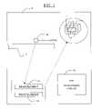
- FIG. 1is a schematic diagram illustrating certain elements of a magnetic disk drive, provided with a monitoring circuit for monitoring for PTP;
- FIG. 2is a block diagram of an embodiment of a computer system
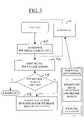
- FIG. 3is a flow chart of a PTP monitoring and correction process
- FIG. 4is a block diagram of PTP monitoring circuit
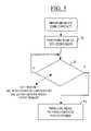
- FIG. 5is a flow chart of a process to sense the head to disk contact.
- FIG. 6is a flow chart of a process to determine the PTP WC.
- a magnetic disk drivemay comprise a unitary housing, and within that housing, a number of elements may be provided, including an input/output interface, a cache buffer memory, a controller, disk RAM, and disk ROM.
- the magnetic disk drivemay have, within the same unitary housing, a spindle motor, a servo, disk media, and read/write heads.
- a motor control circuitis typically provided for controlling the spindle motor, and a servo control is typically provided for controlling the servo.
- read/write electronics and a read/write channelare each provided for facilitating the transfer of information to and from the disk media.
- a magnetic disk drivemay be provided, which contains a complete subsystem for determining when there is an undesired PTP in the write portion of a read/write head and for taking corrective action upon the indication of such an undesired PTP condition.
- the magnetic disk drivemay contain, within its unitary housing, a mechanism for automatically causing the burnishing of the pole tips to prevent the further occurrence of the PTP condition for the given head from which it was detected.
- magnetic disk drivesmay be provided which contain the elements for identifying the presence of an undesired PTP condition for a given read/write head as a part of a test mode, and a corrective action system (e.g., a burnishing system) may be provided which is separate (or separable) from the magnetic disk drive, e.g., so such can be utilized only during the initial setup or manufacture of the magnetic disk drives.
- a corrective action systemmay be provided only for the manufacture of the magnetic disk drive, and may not be provided as part of the resulting magnetic disk drive after it is fully assembled.
- FIG. 1shows a magnetic disk drive having a unitary housing schematically depicted by a rectangle 11 .
- disk mediais provided, including a stack of disk platters (not shown).
- a given disk platter 12is shown in the simplified diagram.
- a different read/write head 10is provided for each side of a disk platter.
- Each read/write head 10may comprise a read element 13 and a write element 14 .
- These elementsare provided in some of the newer higher-performance magnetic disk drives which utilize a traditional U-shaped head for writing data onto the disk while using a magneto-resistive (MR) read element for reading data from the disk media.
- MRmagneto-resistive
- FIG. 1includes an enlarged portion which shows write element 14 comprising pole tips 17 .
- Write element 14comprises a U-shaped head made of conductive material. The U-shaped member is wrapped with coils of wire. A magnetic field is generated and transferred to the disk media in accordance with disk drive write signals that are passed through the coils. By changing the polarity of the electric current passed through the coils, the polarity of the field generated is also changed. The pattern of such magnetic conditions is transferred to the surface of the disk media on disk platter 12 to form a pattern which comprises the resulting encoded version of the data to be retrieved at a later point.
- Poles 17are positioned very close to the surface of disk platter 12 , and are maintained at a specified distance from the surface of the disk platter 12 by an air bearing. If there is contact, or if the distance between the surface of the disk platter 12 and the pole tips 17 becomes unacceptably small, there can be problems with the disk. The head or the disk media can be damaged, and errors can be encountered when retrieving the data and reading the data from the disk media.
- Pole tip protrusioncan be caused by high frequency writing which causes thermal expansion of the pole tips 17 due to, for example, the combined effects of eddy current heating and coil heating.
- PTP phenomenacan cause problems while writing data onto the disk media, such as off track writing, due to frictional forces, as well as high servo PES (position error signal), because the pole tip is dragging the head. These effects could cause drive failure.
- FIG. 2is a block diagram of one embodiment of a personal computer system.
- the illustrated computer systemhas a magnetic disk drive 17 .
- the illustrated magnetic disk drive 17comprises, among other elements, disk media 46 .
- disk media 46comprises magnetic media sputtered onto a metal substrate (the metal may be aluminum).
- the illustrated computer systemcomprises a host system 23 and a magnetic disk drive 17 .
- Magnetic disk drive 17comprises a unitary magnetic disk drive housing which houses an input/output interface 26 , a cache buffer memory 28 , a controller 30 , a RAM (random access memory) 36 , and a ROM (read only memory) 34 .
- Input/output interface 26is connected to cache buffer memory 28 , which is connected to controller 30 .
- Each of the RAM and ROM portions 36 , 34is coupled to controller 30 .
- the magnetic disk drive housingfurther houses motor and servo mechanisms 38 , read/write electronics 40 , and a read channel 42 .
- Read channel 42is coupled to read/write heads 44 , which interact with disk media 46 .
- Read/write heads 44 and disk media 46are also provided within the unitary magnetic disk drive housing (depicted with a schematic dotted line).
- Input/output interface 26may comprise a SCSI, IDE, or ADA interface, just to name a few examples. While a cache buffer memory 28 is not required, such is common.
- controller 22serves as a control portion of the magnetic disk drive.
- Motor and servo control portions (not shown) of motor and servo mechanisms 38 , read/write electronics 40 , and read channel 42collectively comprise hardware interaction circuitry coupling controller 30 to a head/disk assembly, which comprises a spindle motor (not shown), a servo (not shown), read/write heads 44 , and disk media 46 .
- magnetic disk drive 17has in its housing, internal memory, including RAM 36 and ROM 34 . All or a portion of such memory (and any other devices or mechanisms that may be provided in the magnetic disk drive and that serve as memory) may serve as the internal memory for the magnetic disk drive, and may contain information pertinent to the functions and operation of the magnetic disk drive.
- FIG. 3is a flow chart of a PTP test process performed by the illustrated disk drive when it is in a PTP test mode.
- the PTP write current (WC)is determined (by a process to be more fully explained below).
- the PTP WCis the WC at which head disk contact occurs due to PTP.
- the write current(for normal disk drive operation, outside of the PTP test mode) is limited to a value equal to the PTP WC less a specified margin—to provide a “buffer” against undesired PTP in the disk drive.
- a determinationis made as to whether the PTP WC less the margin (the write current limit) is too low. This can be determined by checking if the BER (bit error rate) is unacceptable, a result of having a WC that is too low.
- act 56if the write current limit was too low, corrective action is taken. In this act, the head is burnished and/or the data rate is decreased (thereby decreasing the BER).
- the PTP WCis determined at act 50 while the disk drive is placed under a PTP stress condition—per act 53 .
- Thiscan be accomplished, e.g., by continuously writing for a given period of time, ideally with missing revolutions.
- the track detectionmay be expanded (or the bias changed), to include time after the negation of the write gate (WG). This helps when the pole tip motion away from the disk is faster than the motion towards the disk.
- Another way to add PTP stressis to increase the data rate of the write operation.
- FIG. 4shows a block diagram of a PTP monitoring circuit.
- the illustrated circuit 16comprises a disk contact detection mechanism and a write current (WC) level detector 20 .
- the circuit 16is active when the drive is in a PTP test mode per an input 60 .
- the WC level that occurs when the disk contact is detected due to an undesired PTP conditionis stored at storage 22 .
- the PTP monitoring circuit 16may be part of read channel 15 .
- FIG. 5is a flow chart of a process to sense head to disk contact.
- the headIn an initial act 70 , the head is positioned at a non-zero skew.
- the processdetermines whether the head is off track, whether the bias exceeds a threshold, or whether there is a given SAM or gray code error.
- act 74an indication is made that a head to disk contact has occurred.
- FIG. 6is a flow chart of a process to determine the PTP WC.
- act 80the WC is increased.
- act 82a determination is made as to whether a head to disk contact had been detected. When such contact has been detected, the process proceeds to act 84 .
- act 84the measured write current (WC) is deemed the PTP WC.
Landscapes
- Physics & Mathematics (AREA)
- Electromagnetism (AREA)
- Engineering & Computer Science (AREA)
- Manufacturing & Machinery (AREA)
- Digital Magnetic Recording (AREA)
- Recording Or Reproducing By Magnetic Means (AREA)
Abstract
Description
Claims (30)
Priority Applications (1)
| Application Number | Priority Date | Filing Date | Title |
|---|---|---|---|
| US10/369,179US6980383B2 (en) | 2001-06-18 | 2003-02-19 | Monitoring of phenomena indicative of PTP in a magnetic disk drive |
Applications Claiming Priority (3)
| Application Number | Priority Date | Filing Date | Title |
|---|---|---|---|
| US29896801P | 2001-06-18 | 2001-06-18 | |
| US17357802A | 2002-06-18 | 2002-06-18 | |
| US10/369,179US6980383B2 (en) | 2001-06-18 | 2003-02-19 | Monitoring of phenomena indicative of PTP in a magnetic disk drive |
Related Parent Applications (1)
| Application Number | Title | Priority Date | Filing Date |
|---|---|---|---|
| US17357802AContinuation | 2001-06-18 | 2002-06-18 |
Publications (2)
| Publication Number | Publication Date |
|---|---|
| US20040100255A1 US20040100255A1 (en) | 2004-05-27 |
| US6980383B2true US6980383B2 (en) | 2005-12-27 |
Family
ID=32328668
Family Applications (1)
| Application Number | Title | Priority Date | Filing Date |
|---|---|---|---|
| US10/369,179Expired - Fee RelatedUS6980383B2 (en) | 2001-06-18 | 2003-02-19 | Monitoring of phenomena indicative of PTP in a magnetic disk drive |
Country Status (1)
| Country | Link |
|---|---|
| US (1) | US6980383B2 (en) |
Cited By (23)
| Publication number | Priority date | Publication date | Assignee | Title |
|---|---|---|---|---|
| US7224548B1 (en)* | 2002-01-04 | 2007-05-29 | Maxtor Corporation | Determining contact write current in disk drive using position error signal variance |
| US20070236821A1 (en)* | 2006-04-10 | 2007-10-11 | Iomega Corporation | Detecting head/disk contact in a disk drive using a calibration parameter |
| US7417813B2 (en)* | 2004-05-26 | 2008-08-26 | Seagate Technology Llc | Overlapping data track access |
| US7436620B1 (en) | 2007-05-29 | 2008-10-14 | Western Digital (Fremont), Llc | Method for selecting an electrical power to be applied to a head-based flying height actuator |
| US7440220B1 (en) | 2007-05-29 | 2008-10-21 | Western Digital (Fremont), Llc | Method for defining a touch-down power for head having a flying height actuator |
| US20090128947A1 (en)* | 2007-11-15 | 2009-05-21 | Western Digital (Fremont), Llc | Disk drive determining operating fly height by detecting head disk contact from disk rotation time |
| US7551390B1 (en) | 2007-08-21 | 2009-06-23 | Western Digital Technologies, Inc. | Disk drive to characterize misaligned servo wedges |
| US20090195936A1 (en)* | 2008-02-04 | 2009-08-06 | Western Digital Technologies, Inc. | Disk drive servoing off of first head while determining fly height for second head |
| US7675707B1 (en) | 2008-11-21 | 2010-03-09 | Western Digital Technologies, Inc. | Disk drive employing repeatable disturbance compensation for fly height control |
| US20100142080A1 (en)* | 2008-12-08 | 2010-06-10 | Youping Deng | Methods and apparatus to detect surface characteristics on magnetic read/write heads |
| US7839595B1 (en) | 2008-01-25 | 2010-11-23 | Western Digital Technologies, Inc. | Feed forward compensation for fly height control in a disk drive |
| US7916420B1 (en) | 2010-05-14 | 2011-03-29 | Western Digital Technologies, Inc. | Disk drive employing comb filter for repeatable fly height compensation |
| US8059357B1 (en) | 2010-03-18 | 2011-11-15 | Western Digital Technologies, Inc. | Disk drive adjusting fly height when calibrating head/disk contact |
| US8300338B1 (en) | 2010-09-30 | 2012-10-30 | Western Digital Technologies, Inc. | Disk drive correlating different fly height measurements to verify disk warpage |
| US8320069B1 (en) | 2010-03-18 | 2012-11-27 | Western Digital Technologies, Inc. | Disk drive detecting positive correlation in fly height measurements |
| US8482873B1 (en) | 2008-02-18 | 2013-07-09 | Western Digital Technologies, Inc. | Disk drive employing pulse width modulation of head control signal |
| US8599512B2 (en) | 2011-09-16 | 2013-12-03 | Western Digital Technologies, Inc. | Current sensor comprising differential amplifier biased by leakage current |
| US8681442B2 (en) | 2012-05-11 | 2014-03-25 | Western Digital Technologies, Inc. | Disk drive comprising extended range head proximity sensor |
| US8837081B1 (en) | 2011-12-06 | 2014-09-16 | Western Digital (Fremont), Llc | Laminated touchdown sensor for hard disk drives |
| US8934192B1 (en) | 2008-11-24 | 2015-01-13 | Western Digital Technologies, Inc. | Disk drive determining operating fly height by detecting head disk contact from read signal amplitude variance |
| US8976633B1 (en) | 2014-04-15 | 2015-03-10 | Western Digital Technologies, Inc. | Data storage device calibrating fly height actuator based on laser power for heat assisted magnetic recording |
| US9042208B1 (en) | 2013-03-11 | 2015-05-26 | Western Digital Technologies, Inc. | Disk drive measuring fly height by applying a bias voltage to an electrically insulated write component of a head |
| US9047902B1 (en) | 2011-06-15 | 2015-06-02 | Western Digital (Fremont), Llc | Touchdown sensor having a more stable crystal structure for use in hard disk drives |
Families Citing this family (3)
| Publication number | Priority date | Publication date | Assignee | Title |
|---|---|---|---|---|
| KR100468766B1 (en)* | 2002-09-19 | 2005-01-29 | 삼성전자주식회사 | Method for controlling flying height between head and disk and apparatus thereof |
| KR100468779B1 (en)* | 2002-12-13 | 2005-01-29 | 삼성전자주식회사 | Method for measuring TPTP of a magnetic head and a method for controlling write current thereof |
| JP2005135543A (en)* | 2003-10-31 | 2005-05-26 | Toshiba Corp | Magnetic disk apparatus and write control method |
Citations (6)
| Publication number | Priority date | Publication date | Assignee | Title |
|---|---|---|---|---|
| US5594595A (en)* | 1995-01-19 | 1997-01-14 | Conner Peripherals, Inc. | FM detection of slider-disk interface |
| US5863237A (en)* | 1996-12-04 | 1999-01-26 | Seagate Technology, Inc. | Low speed burnishing of asperities in a disc drive |
| US6084741A (en)* | 1997-01-28 | 2000-07-04 | Samsung Electronics Co., Ltd. | Method for preventing head collision when detection of servo synchronizing signals fails |
| US6195219B1 (en)* | 1998-10-20 | 2001-02-27 | International Business Machines Corporation | Method and apparatus for improving a thermal response of a magnetoresistive element |
| US20020036850A1 (en)* | 2000-09-28 | 2002-03-28 | Seagate Technologies Llc | Enhanced short disc drive self test using historical logs |
| US6693769B2 (en)* | 2001-06-18 | 2004-02-17 | Hitachi Global Storage Technologies Netherlands B.V. | High data rate write head |
- 2003
- 2003-02-19USUS10/369,179patent/US6980383B2/ennot_activeExpired - Fee Related
Patent Citations (6)
| Publication number | Priority date | Publication date | Assignee | Title |
|---|---|---|---|---|
| US5594595A (en)* | 1995-01-19 | 1997-01-14 | Conner Peripherals, Inc. | FM detection of slider-disk interface |
| US5863237A (en)* | 1996-12-04 | 1999-01-26 | Seagate Technology, Inc. | Low speed burnishing of asperities in a disc drive |
| US6084741A (en)* | 1997-01-28 | 2000-07-04 | Samsung Electronics Co., Ltd. | Method for preventing head collision when detection of servo synchronizing signals fails |
| US6195219B1 (en)* | 1998-10-20 | 2001-02-27 | International Business Machines Corporation | Method and apparatus for improving a thermal response of a magnetoresistive element |
| US20020036850A1 (en)* | 2000-09-28 | 2002-03-28 | Seagate Technologies Llc | Enhanced short disc drive self test using historical logs |
| US6693769B2 (en)* | 2001-06-18 | 2004-02-17 | Hitachi Global Storage Technologies Netherlands B.V. | High data rate write head |
Cited By (29)
| Publication number | Priority date | Publication date | Assignee | Title |
|---|---|---|---|---|
| US7224548B1 (en)* | 2002-01-04 | 2007-05-29 | Maxtor Corporation | Determining contact write current in disk drive using position error signal variance |
| US7417813B2 (en)* | 2004-05-26 | 2008-08-26 | Seagate Technology Llc | Overlapping data track access |
| US20070236821A1 (en)* | 2006-04-10 | 2007-10-11 | Iomega Corporation | Detecting head/disk contact in a disk drive using a calibration parameter |
| US7423830B2 (en)* | 2006-04-10 | 2008-09-09 | Iomega Corporation | Detecting head/disk contact in a disk drive using a calibration parameter |
| US7436620B1 (en) | 2007-05-29 | 2008-10-14 | Western Digital (Fremont), Llc | Method for selecting an electrical power to be applied to a head-based flying height actuator |
| US7440220B1 (en) | 2007-05-29 | 2008-10-21 | Western Digital (Fremont), Llc | Method for defining a touch-down power for head having a flying height actuator |
| US7551390B1 (en) | 2007-08-21 | 2009-06-23 | Western Digital Technologies, Inc. | Disk drive to characterize misaligned servo wedges |
| US20090128947A1 (en)* | 2007-11-15 | 2009-05-21 | Western Digital (Fremont), Llc | Disk drive determining operating fly height by detecting head disk contact from disk rotation time |
| US7583466B2 (en) | 2007-11-15 | 2009-09-01 | Western Digital (Fremont), Llc | Disk drive determining operating fly height by detecting head disk contact from disk rotation time |
| US7839595B1 (en) | 2008-01-25 | 2010-11-23 | Western Digital Technologies, Inc. | Feed forward compensation for fly height control in a disk drive |
| US7630162B2 (en) | 2008-02-04 | 2009-12-08 | Western Digital Technologies, Inc. | Disk drive servoing off of first head while determining fly height for second head |
| US8780473B1 (en) | 2008-02-04 | 2014-07-15 | Western Digital Technologies, Inc. | Disk drive selecting a global digital-to-analog setting for a plurality of heads |
| US20090195936A1 (en)* | 2008-02-04 | 2009-08-06 | Western Digital Technologies, Inc. | Disk drive servoing off of first head while determining fly height for second head |
| US8482873B1 (en) | 2008-02-18 | 2013-07-09 | Western Digital Technologies, Inc. | Disk drive employing pulse width modulation of head control signal |
| US7675707B1 (en) | 2008-11-21 | 2010-03-09 | Western Digital Technologies, Inc. | Disk drive employing repeatable disturbance compensation for fly height control |
| US8934192B1 (en) | 2008-11-24 | 2015-01-13 | Western Digital Technologies, Inc. | Disk drive determining operating fly height by detecting head disk contact from read signal amplitude variance |
| US20100142080A1 (en)* | 2008-12-08 | 2010-06-10 | Youping Deng | Methods and apparatus to detect surface characteristics on magnetic read/write heads |
| US7982987B2 (en) | 2008-12-08 | 2011-07-19 | Hitachi Global Storage Technologies Netherlands B.V. | Methods and apparatus to detect surface characteristics on magnetic read/write heads |
| US8059357B1 (en) | 2010-03-18 | 2011-11-15 | Western Digital Technologies, Inc. | Disk drive adjusting fly height when calibrating head/disk contact |
| US8320069B1 (en) | 2010-03-18 | 2012-11-27 | Western Digital Technologies, Inc. | Disk drive detecting positive correlation in fly height measurements |
| US7916420B1 (en) | 2010-05-14 | 2011-03-29 | Western Digital Technologies, Inc. | Disk drive employing comb filter for repeatable fly height compensation |
| US8300338B1 (en) | 2010-09-30 | 2012-10-30 | Western Digital Technologies, Inc. | Disk drive correlating different fly height measurements to verify disk warpage |
| US9047902B1 (en) | 2011-06-15 | 2015-06-02 | Western Digital (Fremont), Llc | Touchdown sensor having a more stable crystal structure for use in hard disk drives |
| US8599512B2 (en) | 2011-09-16 | 2013-12-03 | Western Digital Technologies, Inc. | Current sensor comprising differential amplifier biased by leakage current |
| US8837081B1 (en) | 2011-12-06 | 2014-09-16 | Western Digital (Fremont), Llc | Laminated touchdown sensor for hard disk drives |
| US8681442B2 (en) | 2012-05-11 | 2014-03-25 | Western Digital Technologies, Inc. | Disk drive comprising extended range head proximity sensor |
| US9053730B1 (en) | 2012-05-11 | 2015-06-09 | Western Digital Technologies, Inc. | Disk drive comprising extended range head proximity sensor |
| US9042208B1 (en) | 2013-03-11 | 2015-05-26 | Western Digital Technologies, Inc. | Disk drive measuring fly height by applying a bias voltage to an electrically insulated write component of a head |
| US8976633B1 (en) | 2014-04-15 | 2015-03-10 | Western Digital Technologies, Inc. | Data storage device calibrating fly height actuator based on laser power for heat assisted magnetic recording |
Also Published As
| Publication number | Publication date |
|---|---|
| US20040100255A1 (en) | 2004-05-27 |
Similar Documents
| Publication | Publication Date | Title |
|---|---|---|
| US6980383B2 (en) | Monitoring of phenomena indicative of PTP in a magnetic disk drive | |
| US6266199B1 (en) | Method of apparatus to characterize and limit the effect of disk damage in a hard disk drive | |
| US8711508B2 (en) | Contact detection between a disk and magnetic head | |
| US7423830B2 (en) | Detecting head/disk contact in a disk drive using a calibration parameter | |
| JP4564692B2 (en) | Hard disk drive, defect type detection method on disk, and defect detection method | |
| CN101359481B (en) | Disk drive apparatus and method of adaptively controlling flying height of magnetic head therein | |
| US8416521B2 (en) | Magnetic recording and reproduction device and flying height control method | |
| KR100468767B1 (en) | Method for preventing adjacent track erase in HDD and apparatus thereof | |
| EP2372708B1 (en) | Systems and methods for detecting head contact | |
| US7117399B2 (en) | Method of and apparatus for controlling data storage system according to temperature, and medium | |
| US6956707B2 (en) | Method for look-ahead thermal sensing in a data storage device | |
| KR100416604B1 (en) | Method and apparatus to detect and manage servo sectors with defect on servo pattern area in hard disk drives | |
| US20030210488A1 (en) | Apparatus for look-ahead thermal sensing in a data storage device | |
| US5982568A (en) | Apparatus for detecting error in magnetic head for use in disk storage system | |
| US8139308B2 (en) | Hard disk drive, method of controlling flying height of magnetic head thereof, and recording medium containing computer program thereon | |
| US7525752B2 (en) | Media drive and control method for the same | |
| US6717759B1 (en) | Hindering PTP in a hard disk | |
| US7224548B1 (en) | Determining contact write current in disk drive using position error signal variance | |
| US7561368B2 (en) | Hard disk drive having improved head stability at low temperature and method of applying current to a head of the hard disk drive | |
| US6263462B1 (en) | Testing method and tester | |
| US7382562B2 (en) | Preamplifier for use in data storage devices | |
| US7987317B2 (en) | Data recording device and control method of same | |
| US6445520B1 (en) | Method for detecting mechanical damage in a parking zone of a hard disk drive | |
| US20110134557A1 (en) | Real time monitoring inconsistent operations in a hard disk drive | |
| US7009797B2 (en) | Method of tagging calibration results with temperature, time and/or voltage |
Legal Events
| Date | Code | Title | Description |
|---|---|---|---|
| AS | Assignment | Owner name:MAXTOR CORPORATION, COLORADO Free format text:ASSIGNMENT OF ASSIGNORS INTEREST;ASSIGNORS:BRUNNETT, DON;BANH, DUC;YU, JINGBO;AND OTHERS;REEL/FRAME:014508/0135;SIGNING DATES FROM 20030819 TO 20030910 | |
| AS | Assignment | Owner name:WELLS FARGO BANK, NATIONAL ASSOCIATION, AS COLLATERAL AGENT AND SECOND PRIORITY REPRESENTATIVE, CALIFORNIA Free format text:SECURITY AGREEMENT;ASSIGNORS:MAXTOR CORPORATION;SEAGATE TECHNOLOGY LLC;SEAGATE TECHNOLOGY INTERNATIONAL;REEL/FRAME:022757/0017 Effective date:20090507 Owner name:JPMORGAN CHASE BANK, N.A., AS ADMINISTRATIVE AGENT AND FIRST PRIORITY REPRESENTATIVE, NEW YORK Free format text:SECURITY AGREEMENT;ASSIGNORS:MAXTOR CORPORATION;SEAGATE TECHNOLOGY LLC;SEAGATE TECHNOLOGY INTERNATIONAL;REEL/FRAME:022757/0017 Effective date:20090507 Owner name:JPMORGAN CHASE BANK, N.A., AS ADMINISTRATIVE AGENT Free format text:SECURITY AGREEMENT;ASSIGNORS:MAXTOR CORPORATION;SEAGATE TECHNOLOGY LLC;SEAGATE TECHNOLOGY INTERNATIONAL;REEL/FRAME:022757/0017 Effective date:20090507 Owner name:WELLS FARGO BANK, NATIONAL ASSOCIATION, AS COLLATE Free format text:SECURITY AGREEMENT;ASSIGNORS:MAXTOR CORPORATION;SEAGATE TECHNOLOGY LLC;SEAGATE TECHNOLOGY INTERNATIONAL;REEL/FRAME:022757/0017 Effective date:20090507 | |
| FPAY | Fee payment | Year of fee payment:4 | |
| AS | Assignment | Owner name:SEAGATE TECHNOLOGY LLC, CALIFORNIA Free format text:RELEASE;ASSIGNOR:JPMORGAN CHASE BANK, N.A., AS ADMINISTRATIVE AGENT;REEL/FRAME:025662/0001 Effective date:20110114 Owner name:MAXTOR CORPORATION, CALIFORNIA Free format text:RELEASE;ASSIGNOR:JPMORGAN CHASE BANK, N.A., AS ADMINISTRATIVE AGENT;REEL/FRAME:025662/0001 Effective date:20110114 Owner name:SEAGATE TECHNOLOGY INTERNATIONAL, CALIFORNIA Free format text:RELEASE;ASSIGNOR:JPMORGAN CHASE BANK, N.A., AS ADMINISTRATIVE AGENT;REEL/FRAME:025662/0001 Effective date:20110114 Owner name:SEAGATE TECHNOLOGY HDD HOLDINGS, CALIFORNIA Free format text:RELEASE;ASSIGNOR:JPMORGAN CHASE BANK, N.A., AS ADMINISTRATIVE AGENT;REEL/FRAME:025662/0001 Effective date:20110114 | |
| AS | Assignment | Owner name:THE BANK OF NOVA SCOTIA, AS ADMINISTRATIVE AGENT, CANADA Free format text:SECURITY AGREEMENT;ASSIGNOR:SEAGATE TECHNOLOGY LLC;REEL/FRAME:026010/0350 Effective date:20110118 Owner name:THE BANK OF NOVA SCOTIA, AS ADMINISTRATIVE AGENT, Free format text:SECURITY AGREEMENT;ASSIGNOR:SEAGATE TECHNOLOGY LLC;REEL/FRAME:026010/0350 Effective date:20110118 | |
| FPAY | Fee payment | Year of fee payment:8 | |
| AS | Assignment | Owner name:SEAGATE TECHNOLOGY LLC, CALIFORNIA Free format text:TERMINATION AND RELEASE OF SECURITY INTEREST IN PATENT RIGHTS;ASSIGNOR:WELLS FARGO BANK, NATIONAL ASSOCIATION, AS COLLATERAL AGENT AND SECOND PRIORITY REPRESENTATIVE;REEL/FRAME:030833/0001 Effective date:20130312 Owner name:SEAGATE TECHNOLOGY INTERNATIONAL, CAYMAN ISLANDS Free format text:TERMINATION AND RELEASE OF SECURITY INTEREST IN PATENT RIGHTS;ASSIGNOR:WELLS FARGO BANK, NATIONAL ASSOCIATION, AS COLLATERAL AGENT AND SECOND PRIORITY REPRESENTATIVE;REEL/FRAME:030833/0001 Effective date:20130312 Owner name:EVAULT INC. (F/K/A I365 INC.), CALIFORNIA Free format text:TERMINATION AND RELEASE OF SECURITY INTEREST IN PATENT RIGHTS;ASSIGNOR:WELLS FARGO BANK, NATIONAL ASSOCIATION, AS COLLATERAL AGENT AND SECOND PRIORITY REPRESENTATIVE;REEL/FRAME:030833/0001 Effective date:20130312 Owner name:SEAGATE TECHNOLOGY US HOLDINGS, INC., CALIFORNIA Free format text:TERMINATION AND RELEASE OF SECURITY INTEREST IN PATENT RIGHTS;ASSIGNOR:WELLS FARGO BANK, NATIONAL ASSOCIATION, AS COLLATERAL AGENT AND SECOND PRIORITY REPRESENTATIVE;REEL/FRAME:030833/0001 Effective date:20130312 | |
| REMI | Maintenance fee reminder mailed | ||
| LAPS | Lapse for failure to pay maintenance fees | Free format text:PATENT EXPIRED FOR FAILURE TO PAY MAINTENANCE FEES (ORIGINAL EVENT CODE: EXP.) | |
| STCH | Information on status: patent discontinuation | Free format text:PATENT EXPIRED DUE TO NONPAYMENT OF MAINTENANCE FEES UNDER 37 CFR 1.362 | |
| FP | Lapsed due to failure to pay maintenance fee | Effective date:20171227 | |
| AS | Assignment | Owner name:SEAGATE TECHNOLOGY PUBLIC LIMITED COMPANY, CALIFORNIA Free format text:RELEASE BY SECURED PARTY;ASSIGNOR:THE BANK OF NOVA SCOTIA;REEL/FRAME:072193/0001 Effective date:20250303 Owner name:SEAGATE TECHNOLOGY, CALIFORNIA Free format text:RELEASE BY SECURED PARTY;ASSIGNOR:THE BANK OF NOVA SCOTIA;REEL/FRAME:072193/0001 Effective date:20250303 Owner name:SEAGATE TECHNOLOGY HDD HOLDINGS, CALIFORNIA Free format text:RELEASE BY SECURED PARTY;ASSIGNOR:THE BANK OF NOVA SCOTIA;REEL/FRAME:072193/0001 Effective date:20250303 Owner name:I365 INC., CALIFORNIA Free format text:RELEASE BY SECURED PARTY;ASSIGNOR:THE BANK OF NOVA SCOTIA;REEL/FRAME:072193/0001 Effective date:20250303 Owner name:SEAGATE TECHNOLOGY LLC, CALIFORNIA Free format text:RELEASE BY SECURED PARTY;ASSIGNOR:THE BANK OF NOVA SCOTIA;REEL/FRAME:072193/0001 Effective date:20250303 Owner name:SEAGATE TECHNOLOGY INTERNATIONAL, CAYMAN ISLANDS Free format text:RELEASE BY SECURED PARTY;ASSIGNOR:THE BANK OF NOVA SCOTIA;REEL/FRAME:072193/0001 Effective date:20250303 Owner name:SEAGATE HDD CAYMAN, CAYMAN ISLANDS Free format text:RELEASE BY SECURED PARTY;ASSIGNOR:THE BANK OF NOVA SCOTIA;REEL/FRAME:072193/0001 Effective date:20250303 Owner name:SEAGATE TECHNOLOGY (US) HOLDINGS, INC., CALIFORNIA Free format text:RELEASE BY SECURED PARTY;ASSIGNOR:THE BANK OF NOVA SCOTIA;REEL/FRAME:072193/0001 Effective date:20250303 |