US6980299B1 - Systems and methods for imaging a sample - Google Patents
Systems and methods for imaging a sampleDownload PDFInfo
- Publication number
- US6980299B1 US6980299B1US10/272,171US27217102AUS6980299B1US 6980299 B1US6980299 B1US 6980299B1US 27217102 AUS27217102 AUS 27217102AUS 6980299 B1US6980299 B1US 6980299B1
- Authority
- US
- United States
- Prior art keywords
- spectral density
- cross
- modified
- cross spectral
- combination
- Prior art date
- Legal status (The legal status is an assumption and is not a legal conclusion. Google has not performed a legal analysis and makes no representation as to the accuracy of the status listed.)
- Expired - Lifetime, expires
Links
Images


Classifications
- G—PHYSICS
- G01—MEASURING; TESTING
- G01B—MEASURING LENGTH, THICKNESS OR SIMILAR LINEAR DIMENSIONS; MEASURING ANGLES; MEASURING AREAS; MEASURING IRREGULARITIES OF SURFACES OR CONTOURS
- G01B9/00—Measuring instruments characterised by the use of optical techniques
- G01B9/02—Interferometers
- G01B9/0209—Low-coherence interferometers
- G01B9/02091—Tomographic interferometers, e.g. based on optical coherence
- G—PHYSICS
- G01—MEASURING; TESTING
- G01B—MEASURING LENGTH, THICKNESS OR SIMILAR LINEAR DIMENSIONS; MEASURING ANGLES; MEASURING AREAS; MEASURING IRREGULARITIES OF SURFACES OR CONTOURS
- G01B9/00—Measuring instruments characterised by the use of optical techniques
- G01B9/02—Interferometers
- G01B9/02083—Interferometers characterised by particular signal processing and presentation
Definitions
- the present inventiongenerally relates to systems and methods for imaging a sample by processing optical coherence tomography (OCT) signals.
- OCToptical coherence tomography
- the present inventionis directed to systems and methods for imaging a sample in which OCT signals are processed to modify a spectral shape of a source of light and/or compensate for a dispersion between a portion of the light transmitted to the sample and a portion of the light transmitted to a reference arrangement.
- the systems and method of the present inventioncan also implement a demodulation algorithm to extract intensity, polarization and/or Doppler shift information from the OCT signals.
- OCToptical coherence tomography
- a sourcee.g. , a light source
- a particular coherence lengthe.g. , between about 1 micron and about 1 meter
- an interferometermay be used with such arrangement, such as a Michelson interferometer, a Mach Zehnder interferometer, etc.
- light from the sourceis routed through a fiber. This light enters a fiberoptic coupler (e.g.
- the fiberoptic couplerdivides the light into two portions (e.g. , equal portions). After the light is divided, a first portion of the light is transmitted towards a reference arrangement (e.g. , a reflective arrangement such as a mirror) via a reflective arm having a variable length, and a second portion of the light is transmitted towards the sample via a sample arm having a constant length. Moreover, the first and second portions of light return or reflect from the reference arrangement and the sample, respectively, and recombine within the fiberoptic coupler. The recombined light is then transmitted to a detector. Further, the detector is coupled to a computer arrangement which extracts information from the signal received from the detector. Specifically, this information is associated with interference fringes of light from the sample and the reference arrangement to generate an image of the sample.
- a reference arrangemente.g. , a reflective arrangement such as a mirror
- the first and second portions of lightreturn or reflect from the reference arrangement and the sample, respectively, and recombine within the fiberoptic coupler.
- the interference fringesare only formed when the distance propagated by the first portion of light matches the distance propagated by the second portion of light within the coherence length of the source. Therefore, when the length of the reference arm increases from a particular length to a further length, and the length of the sample arm remains constant, the detected light will be such light which is propagated further into the sample than when the length of the reference arm has the particular length. Consequently, by adjusting the length of the reference arm to detect a plurality of signals, substantially the entire sample may be imaged.
- the source used in this OCT systemhas a Gaussian spectrum.
- sources having Gaussian structuresare difficult to manufacture, and many readily available sources have non-Gaussian structures.
- sources having non-Gaussian spectrumsmay generate side lobes in a coherence envelope of the interference pattern, which can generate spurious structures within the image of the sample. Consequently, portions of the image may be unclear.
- OCT signalscan be processed to modify the spectral shape of a source having a non-Gaussian spectrum, such that the side lobes in the coherence envelope are reduced or eliminated.
- the OCT signalscan be processed to compensate for the dispersion between the light which is transmitted to the reference arrangement and the light which is transmitted to the sample.
- the OCT signalscan be processed to implement a demodulation algorithm for extracting intensity, polarization and/or Doppler shift information from the OCT signals.
- a first combination of light and a second combination of lightare received ( e.g. , by a detector), in which a first cross-correlation function is associated with the first combination and a second cross correlation function is associated with the second combination.
- Each of the first and the second combinationsinclude a first portion of light which is received from a reference arrangement (e.g. , a reflective arrangement, such as a mirror) and a second portion of light which is received from the sample (e.g. , a microstructure in biological structure, such as tissue in a human).
- a first relative position of the sample associated with the first combinationis different than a second relative position of the sample associated with the second combination.
- the first combination of light(e.g. , first beam of light) can be transmitted from a source to a fiberoptic coupler (e.g. , a beam splitter), and the fiberoptic coupler can divide the first combination of light into the first portion of light and the second portion of light.
- the first portion of the first combinationcan be transmitted to the reference arrangement, and the second portion of the first combination can be transmitted to the sample.
- the first portion of the first combinationmay reflect off of the reference arrangement and return to the fiberoptic coupler, and the second portion of the first combination may reflect off of the sample and return to the fiberoptic coupler, such that the first portion of the first combination and the second portion of the first combination are recombined at the fiberoptic coupler.
- a distance between the fiberoptic coupler and the reference arrangementcan be altered (e.g. , by about 2 mm).
- the first combinationis then transmitted to a detector, and a computer arrangement coupled to the detector may receive a signal or signals associated with the first combination.
- a position of the source and/or a position of the samplecan be altered (i.e. , the relative position of the sample can be altered), and the second combination of light (e.g. , second beam of light) can be transmitted from the source to the fiberoptic coupler.
- the source and/or the samplecan be moved in the X, Y, and/or Z direction.
- the fiberoptic couplercan divide the second combination of light into the first portion of light and the second portion of light. Further, the first portion of the second combination can be transmitted to the reference arrangement, and the second portion of the second combination can be transmitted to the sample.
- the first portion of the second combinationmay reflect off of the reference arrangement and return to the fiberoptic coupler
- the second portion of the second combinationmay reflect off of the sample and return to the fiberoptic coupler, such that the first portion of the second combination and the second portion of the second combination are recombined at the fiberoptic coupler.
- the distance between the fiberoptic coupler and the reference arrangementcan be altered ( e.g. , by about 2 mm).
- the distance between the fiberoptic coupler and the reference arrangementcan be altered in the same manner as during the transmission of the first combination.
- the second combinationis then transmitted to the detector, and the computer arrangement may receive a signal or signals associated with the second combination. This may continue for a predetermined number of combinations of light (e.g. , any number of combinations of light greater than one combination which are sufficient to image the sample).
- the first cross correlation functioncan be transformed ( e.g. , using a Fourier transform) into a first complex cross spectral density
- the second cross correlation functioncan be transformed ( e.g. , using a Fourier transform) into a second complex cross spectral density
- a third complex cross spectral densitycan be determined which is approximately an average of the first complex cross spectral density and the second complex cross spectral density
- a particular ( e.g. , desired) width of a Gaussian spectra of the sourcecan be determined based on the third complex cross spectral density.
- an area, average amplitude, and width of the third complex cross spectral densitycan be determined, and the particular width can be determined based on the area, the average amplitude, and the width of the third complex cross spectral density.
- a correction curvecan be determined based on a ratio between the Gaussian spectra and the third complex cross spectral density, and the first complex cross spectral density and the second complex cross spectral density can be modified as a function of the correction curve.
- the first complex cross spectral densitycan be multiplied by the correction curve in order to obtain a first modified complex cross spectral density
- the second complex cross spectral densitycan be multiplied by the correction curve in order to obtain a second modified complex cross spectral density.
- the first modified complex cross spectral densitycan then be transformed ( e.g. , using an inverse Fourier transform) into a first modified cross correlation function
- the second modified complex cross spectral densitycan be transformed ( e.g. , using an inverse Fourier transform) into a second modified cross correlation function.
- a coherence function envelope of the samplecan be determined based on the first modified cross correlation function and the second modified cross correlation function.
- the first cross correlation functioncan be transformed ( e.g. , using a Fourier transform) into the first complex cross spectral density and the second cross correlation function can be transformed ( e.g. , using a Fourier transform) into the second complex cross spectral density.
- first complex cross spectral densitycan be modified to implement a phase shift of the first complex cross spectral density
- second complex cross spectral densitycan be modified in order to implement a phase shift of the second complex cross spectral density.
- first complex cross spectral density and/or the second complex cross spectral densitycan be multiplied by a predetermined factor to obtain a first modified complex cross spectral density and/or a second modified complex cross spectral density, respectively, and the predetermined factor can include a particular quadratic phase shifting term.
- an image of the samplecan be generated based on the first cross correlation function and/or the second cross correlation function, and an average variance associated with the image of the sample can be determined.
- the first modified complex cross spectral densitycan be transformed ( e.g. , using an inverse Fourier transform) into a third cross correlation function and/or the second modified complex cross spectral density can be transformed ( e.g. , using an inverse Fourier transform) into a fourth cross correlation function.
- a modified image of the samplecan be generated based on the third cross correlation function and/or the fourth cross correlation function, and an average variance associated with the modified image of the sample can be determined.
- the particular quadratic phase shifting termcan then be iteratively altered in order to generate additional modified images of the sample until the average variance associated with the image of the sample is maximized. It will be understood by those of ordinary skill in the art that the second exemplary embodiment of the present invention can be used in combination with, or independent of, the first exemplary embodiment of the present invention.
- first cross correlation functione.g. , by multiplying it by a particular factor, such as e ⁇ 2kz
- second cross correlation functione.g. , by multiplying it by the particular factor
- an average of the first modified cross correlation function and/or an average of the second modified cross correlation functionmay be determined over a first frequency range (e.g.
- the first modified cross correlation function and/or the second modified cross correlation functioncan be transformed into a first complex cross spectral density and/or a second complex cross spectral density, respectively. Then, the exemplary embodiments of the present invention may be performed at a reduced bandwidth range.
- the first cross correlation functionmay be transformed into a first complex cross spectral density
- the second cross correlation functionmay be transformed into a second complex cross spectral density.
- a frequency range of the first complex cross spectral density and/or the second complex cross spectral densitycan be modified or shifted from a first frequency range (e.g. , between about 600 Hz and about 1000 Hz) to a second frequency range ( e.g. , between about ⁇ 200 Hz and about 200 Hz). Then, the exemplary embodiments of the present invention may be performed at a reduced bandwidth range.
- FIG. 1is a schematic diagram of a first exemplary embodiment of a system according to the present invention for imaging a sample.
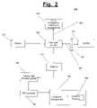
- FIG. 2is a schematic diagram of a second exemplary embodiment of a system according to the present invention for imaging the sample.
- FIG. 3is a graph depicting an ideal Gaussian spectrum, a spectrum for a non-Gaussian source, and a Gaussian fit for the spectrum of the non-Gaussian source according to an exemplary embodiment of the present invention.
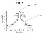
- FIG. 4is a graph depicting an unmodified coherence envelope with side lobes, and a modified coherence envelope with reduced side lobes according to an exemplary embodiment of the present invention.
- FIG. 5is an image of an exemplary onion cell based on the unmodified coherence envelope of FIG. 4 , and an image of the onion cell based on the modified coherence envelope of FIG. 4 .
- FIG. 6is a graph depicting a depth profile of the image based on the unmodified coherence envelope of FIG. 4 , and a depth profile of the image based on the modified coherence envelope of FIG. 4 .
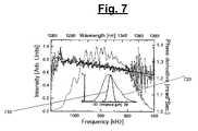
- FIG. 7is a graph of a spectrum and phase derivative of the source as a function of frequency, including an insert of an unmodified coherence envelope and a modified coherence envelope according to an exemplary embodiment of the present invention.
- FIG. 8is an image of an ex-vivo human skin graft based on the unmodified coherence envelope of FIG. 7 , and an image of the ex vivo human skin graft based on the modified coherence envelope of FIG. 7 .
- FIG. 9is a flow diagram of a first exemplary embodiment of a method according to the present invention for imaging the sample.
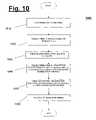
- FIG. 10is a flow diagram of a second exemplary embodiment of a method according to the present invention for imaging the sample.
- FIG. 11is a flow diagram of a third exemplary embodiment of a method according to the present invention for imaging the sample.
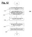
- FIG. 12is a flow diagram of a fourth exemplary embodiment of a method according to the present invention for imaging the sample.
- FIG. 13is a flow diagram of a fifth exemplary embodiment of a method according to the present invention for imaging the sample.
- FIGS. 1–13like numerals being used for like corresponding parts in the various drawings.
- the system 100(e.g. , a system 100 based on a Michelson or a Mach Zehnder interferometer) can include a source 110 coupled to a fiberoptic coupler 120 ( e.g. , a beam splitter).
- the system 100also may include a reference arrangement (e.g. , a reflective arrangement 130 such as a mirror, a delay arrangement 130 ′ of FIG. 2 , etc.) and a sample 140 (e.g. , a microstructure in biological structure, such as tissue in a human).
- a path between the fiberoptic coupler 120 and the reflective arrangement 130may be defined as a reference arm 150
- a path between the fiberoptic coupler 120 and the sample 140may be defined as a sample arm 160 .
- the system 100can also include a detector 170 , and a computer arrangement 180 coupled to the detector 170 .
- the computer arrangement 180can be coupled to the detector 170 via an analog data processing unit 185 and/or an A/D converter 190 .
- a software program 195may be executed by the computer arrangement 180 when this computer arrangement 180 receives signals (e.g. , data) from the detector 170 to extract desired information from the signals, such as structural images, polarization images and flow images.
- the computer arrangement 180can be configured to modify the spectral shape of the source 110 (i.e.
- a first combination of beam of light(not shown) can be transmitted from the source 110 to the fiberoptic coupler 120 , and the fiberoptic coupler 120 can divide the first beam of light into a first portion of light and a second portion of light.
- the first portioncan be transmitted to the reflective arrangement 130
- the second portioncan be transmitted to the sample 140 .
- the first portionmay reflect off of the reflective arrangement 130 and return to the fiberoptic coupler 120
- the second portionmay reflect off of the sample 140 and return to the fiberoptic coupler 120 . In this manner, the first portion and the second portion are recombined at the fiberoptic coupler 120 .
- the distance between the fiberoptic coupler and the reference arrangementcan be altered (e.g. , by about 2 mm).
- the recombined first beam of lightis then transmitted to the detector 170 , and the computer arrangement 180 receives a signal or signals associated with the first beam of light.
- the position of the source 110 and/or the position of the sample 140can be altered (i.e. , the relative position of the sample 140 can be altered), and the second combination or beam of light can be transmitted from the source 110 to the fiberoptic coupler 120 .
- the source 110 and/or the sample 140can be moved in the X, Y, and/or Z direction.
- the processmay be repeated until a predetermined number of signals are received by the computer arrangement 180 (e.g. , a number of signals sufficient to allow the computer arrangement 180 to generate an image of the sample 140 ).
- system 100for imaging the sample is illustrated.
- system 100also includes a probe 145 positioned between the fiberoptic coupler 120 and the sample 140 .
- the probe 145may be scanned over the sample 140 to generate two or three dimensional data.
- the reflective arrangement 130may be replaced by the delay arrangement 130 ′.
- Described belowis an exemplary digital spectral shaping technique to reduce the side lobes (e.g., ringing) of the axial point spread function in Optical Coherence Tomography for non-Gaussian shaped source spectra, according to the present invention.
- a temporal coherence or, equivalently, the source spectral bandwidthmay control the axial point spread function that determines the depth of the microstructure.
- several methodscan be used to generate light with low temporal and high spatial coherence. In virtually all of these techniques, special care should be taken to generate spectral shapes that resemble a Gaussian profile. Non-Gaussian spectral shapes would result in side lobes in the coherence envelope that generate spurious structures in the OCT images.
- R(z)is preferably the interference part of the signal detected at the photo detectors.
- the intensity I(z) back-scattered from the sample armis preferably proportional to the square of R(z), I(z) ⁇ R 2 (z).
- the spectral-shaping techniqueshapes the source spectrum by Fourier transforming the interferometric signal in Equation 1, then applying a correction to each Fourier component such that the spectrum becomes Gaussian. After an inverse transform, the ideal coherence function for a Gaussian source spectrum can be obtained.
- OCT fringe data for an imagecan be obtained, which consists of obtaining a plurality of cross correlation functions R(z) at different locations within the sample 140 .
- the cross correlation functionsare Fourier transformed to a obtain complex cross spectral density for each cross correlation function: R(z) ⁇ >S(k).
- is averaged to obtain ⁇
- >can be used to obtain an estimate for Gaussian function, e.g. , by calculating the zero'th, first and second moment.
- can be subtracted first.
- the noise componentcan be estimated by assuming a white noise spectrum, and subtracting a constant from the spectral density
- the noise componentmay be estimated by performing a measurement R(z) with the sample arm blocked, thus obtaining an estimate of the sum of the electronic noise spectrum, shot noise spectrum, source noise spectrum and other noise sources.
- a spectra correction curve SC(k)can be determined by taking the ratio of Gaussian and averaged spectral density ⁇
- each complex spectral density S(k)can be multiplied by the spectral correction curve SC(k) to obtain the spectrally corrected complex spectral density.
- an inverse Fourier transformmay be performed on the spectrally corrected complex spectral density to obtain the spectrally corrected cross correlation function.
- the spectrally corrected cross correlation functioncan be demodulated to obtain structural information of depth profile (A-line). This structural information would likely have reduced side lobes due to the reshaping of the spectrum into a more Gaussian form.
- the noise penalty and the variance of the demodulated depth profilecan be analyzed to adapt the spectral filter by adapting the zero'th, first and second moment of the Gaussian fit to improve image quality.
- the optimal correction curvecan be found for a particular measurement environment (e.g., system configuration, target, application or patient), the correction can be applied immediately without the iterative procedure.
- FIG. 3depicts an exemplary spectrum 310 which can be calculated from the average of the square root of the power spectrum of 500 A-lines (10,000 samples per A-line, zero padded to 16,384) by Fourier-transforming the interferometric responses to a single surface.
- the dashed curve 320is a Gaussian fit to the spectrum 310 , determined by the zero'th, first and second moments of the spectral density.
- the center wavelength and FWHM of the ideal Gaussian 330are preferably 823 nm and 49 nm, respectively.
- the ratio of the Gaussian fit 320 and measured spectral densitydefine a spectral correction curve SC( ⁇ ), or equivalently SC(k).
- the spectrally filtered response of each depth profilecan be obtained by Fourier-transforming each individual depth profile, multiplying the resulting spectrum with SC(k), and performing the inverse transform thereon.
- FIG. 4shows an exemplary illustration of a coherence function envelope 400 which can be obtained by digital quadrature demodulation with a spatial resolution of 1.6 ⁇ m.
- an unmodified coherence envelope 410is provided before spectral shaping for a single surface (glass slide), and a modified coherence envelope 420 with side lobe reduction at specific locations is also shown.
- the increase in the noise floor far from the coherence envelope 400is approximately 8.5 dB, and the FWHM of the coherence envelope is approximately 6.0–6.5 ⁇ m.
- the distancecan be calibrated using the front and back reflection from a 1 mm thick microscope slide with refractive index of, e.g., 1.5.
- spectral shapingis not only feasible for (e.g., highly) reflective single surfaces, but that it also actually improves images of biological structures, it is possible to image a section of e.g. , an onion skin. For example, a total of 6 images can then be acquired at the same location. Each image may take approximately 1 second to be acquired, scanning a width of 1 mm, and each image is preferably processed both without and with spectral shaping.
- the spectral densitycan be determined from the image data itself by calculating the square root of the power spectrum for each individual A-line in the image and averaging over all A-lines ( 500 ). To obtain the Gaussian fit, the zero'th moment (the area) of the spectral density can be calculated.
- the values determined from the glass slide measurementare preferably utilized.
- the spectral correction curvecan be calculated independently for each image from the Gaussian fit and the spectral density.
- the image spectraare scaled vertically such that the Gaussian fits to the image and glass slide spectra exactly overlap.
- FIG. 5depicts an exemplary side-by-side illustration of uncorrected images 510 , and spectrally shaped images 520 after summing the six individual images to reduce background noise.
- Both exemplary images illustrated in FIG. 5are gray scale coded over a dynamic range of 40 dB (e.g., from maximum signal in the image to the noise level) and cropped to 600 ⁇ 480 ⁇ m (W ⁇ D). The image can be magnified in the depth direction by a factor of 2 to increase the visibility of the side lobes.
- FIG. 6shows exemplary single depth profiles 610 and 620 averaged over 4 A-lines before and after spectral correction, and the achieved side lobe reduction in between the position of the arrows of FIG. 5 , respectively.
- the increase in the noise floor determined by averaging the signal in the air above the sample surfacecan preferably be only approximately 0.9 dB.
- the increase in the noise floorcan be estimated as follows.
- the intensity I(z) reflected from the sample armis preferably proportional to the square of the interferometric intensity R(z) in Equation 1.
- the curve SC(k)gives a multiplication factor for each Fourier component R(k), which consists of a signal R s (k) and a noise R n (k) contribution.
- the average noise level ⁇ R n 2 (z)>is equal to ⁇
- the increase in the noise levelis given by ⁇ SC 2 (k)
- this noise levelcan be reduced to 10*log ⁇ SC 2 (k)> in dB.
- For the glass slideit is possible to calculate a value of 8.65 dB, which corresponds well to a measured value of 8.5 dB, and for the image which have been calculated—a value of 0.97 dB, which corresponds to a measured value of 0.9 dB.
- the 8.5 dB increase in the noise level for the glass slideis mainly due to the large value of SC(k) between 855 and 867 nm (see FIG. 3 ).
- the peak values of the coherence envelopesare proportional to ⁇
- dk⁇ SC(k)
- the first and second moments as determined from the Glass slidewere used as parameters for the Gaussian fit to the spectral density obtained from the onion sample.
- the first and second momentdirectly from the spectral density of the onion sample.
- an autocorrelation functione.g. , a point response.
- a good estimate of the source spectrumcan be obtained from the cross correlation function by averaging the spectral density
- could be subtracted first.
- the noise componentcan be estimated by assuming a white noise spectrum, and subtracting a constant from the spectral density
- the noise componentcould be estimated by performing a measurement of R(z) with the sample arm blocked, thus obtaining an estimate of the sum of the electronic noise spectrum, shot noise spectrum, source noise spectrum and other noise sources.
- the optimal choice of the first and second moment for the target Gaussian in a particular measurementcould also be determined by selecting the maximum allowable increase in the noise floor.
- the Gaussian functioncan be replaced by any other type of function that is advantageous for an image quality improvement and/or side lobe reduction.
- One of the benefits of the present inventionis that the spectral shaping procedure enables the use of non-Gaussian source spectra in the OCT. A quantitative analysis of the accompanying signal to noise penalty can also be implemented.
- Phase sensitive digital signal processing techniquescan be used to remove a broadening of the response function due to a Group Delay Dispersion (“GDD”) in post-processing. It is possible for the phase sensitive digital signal processing to also compensate for higher order dispersion terms in unbalanced OCT systems. GDD introduces a linear dependence of the phase derivative on frequency (or wavelength). Third and fourth order dispersions would likely manifest themselves as quadratic and cubic dependencies, respectively. Ultimately, depth dependent sample dispersion could be corrected for.
- GDDGroup Delay Dispersion
- a second exemplary embodiment of a method 1000 for compensating for dispersion of light in order to image the sample 140is depicted.
- OCT fringe data for an imageis obtained. This step may consist of obtaining a plurality of cross correlation functions R(z) at different sample locations.
- the depth profile R(z)is demodulated to obtain the structural profile I(z).
- the average variance ⁇ I 2 (z)>is calculated for the full image ( e.g. , all depth profiles).
- each of the cross correlation functionsare Fourier-transformed to obtain complex spectral density: R(z) ⁇ >S(k).
- step 1050an inverse Fourier transform is performed on ⁇ tilde over (S) ⁇ (k), ⁇ tilde over (S) ⁇ (k) ⁇ > ⁇ tilde over (R) ⁇ (z), and the GDD corrected depth profile ⁇ tilde over (R) ⁇ (z) is demodulated to obtain the structural profile I(z), in which I(z) proportional to the intensity reflected from the sample arm.
- step 1060the average variance ⁇ I 2 (z)> is calculated for the full image (all depth profiles).
- step 1060the variance ⁇ I 2 (z)> is maximized through an iterative procedure by varying a ( e.g. , by performing steps 1040 and 1050 a plurality of times). When a maximum is found for a, the optimal GDD correction has likely been found.
- the correctioncan be applied immediately without the iterative procedure.
- the GDD compensationcan be demonstrated by experimentally introducing 4.4 ⁇ 10 3 fS 2 GDD in the reference arm.
- GDDcan be measured by a Fourier transformation of the interferometric response to a single surface.
- the phase of each Fourier componentcan be calculated by taking the arc tangent of the ratio of imaginary and real parts.
- the power spectrum and first derivative of the phase, averaged over 1000 depth profiles,can be provided as a function of frequency.
- a linear fit to the first derivative of the phasemay yield a slope of 1.36 ⁇ 10 ⁇ 7 mrad s 2 , corresponding to 4.7 ⁇ 10 3 fS 2 GDD. Correcting for this quadratic phase shift in the Fourier domain of the interferometric signal may preferably remove the GDD in each individual depth profile.
- the inset of FIG. 7shows the coherence envelopes 710 and 720 of the response to a single surface before and after digital processing, respectively, averaged over 1000 depth profiles. The resulting coherence envelope 720 overlaps the coherence envelope 710 of a dispersion balanced system.
- a human skin graftcan be imaged with an unbalanced GDD system.
- the left image 810 of FIG. 8shows the effect of an unbalanced GDD
- the right image 820 of FIG. 8shows the result of a digital GDD compensation on the same data set, where a prior knowledge on the amount of GDD in the system can preferably be used.
- the fit parameter amay be determined beforehand.
- the GDDpreferably broadens the point response function.
- the intensity reflected from the sample arm I(z)is proportional to the square of R(z).
- This broadening of the response function I(z) due to GDDreduces the variance ⁇ I 2 (z)>.
- the variance of ⁇ I 2 (z)>likely does not change by introducing a quadratic or higher order phase shift due to the Parsefal's theorem.
- the variance ⁇ I 2 (z)>is a criterion to optimize the depth profile I(z) by a compensation of a non-linear dispersion.
- R(z)is the interference part of the signal detected at the photo detectors.
- the intensity I(z) back-scattered from the sample armcan be proportional to the square of R(z), I(z) ⁇ R 2 (z).
- the coherence functionis given by; R ⁇ ( z ) ⁇ ⁇ ⁇ ⁇ i ⁇ Re ⁇ ⁇ exp ⁇ ( i2k ⁇ ( z - z i ) ) ⁇ S ⁇ ( k ) ⁇ d k , where R(z) is the measured interference part of the OCT signal.
- the sine and cosine components of the signal carriercan be extracted by multiplying R(z) with the sine and cosine term, respectively, and averaging over a single cycle of the oscillation.
- the inverse ransform [R(q ⁇ 2k 0 )]preferably results in a reduced size, in which the signal is averaged over a number of points proportional to the reduction of the size of the Fourier spectrum.
- An example of a signal bandis shown in FIGS. 3 and 7 .
- Spectral filteringcan be implemented seamlessly by using the above-described technique according to the present invention.
- the Fourier spectrumis available before shifting and the inverse transform.
- the spectral filtercan be applied in the Fourier domain before the inverse Fourier transform is applied.
- the sine and cosine components of the OCT signal as a function of zcan be used to calculate the Stokes parameters (e.g. , as described in U.S. Pat. No. 6,208,415, the entire disclosure of which is incorporated herein by reference) and the phase at each point z by taking the arc-tangent of the ratio of the sine and cosine components.
- the phasecan be used to calculate the Doppler shift between the adjacent A-lines.
- the above-described method and system for processing the OCT signalscan extract the intensity and the phase at each location z in the OCT signal R(z) in an efficient manner, perform a FFT on the signal, and also implement an inverse FFT on a frequency shifted and reduced data set that immediately provides the sine and cosine components of the signal at location z, averaged over a section ⁇ z (determined by the amount the original FFT is reduced).
- These method and systemare computationally efficient due to the reduced size of the inverse transform. They render, e.g. , immediately the cosine and sine components of the signal for further processing.
- the method and system of the present inventionallow for spectral correction and dispersion compensation in an efficient manner by applying the correction and compensation on the data set in the Fourier domain.
- a third exemplary embodiment of a method 1100 according to the present invention for reducing a bandwidth range over which Fourier transforms and inverse Fourier transforms are performed by the software program 195 to image the sample 140is depicted.
- the cross correlation functionsare Fourier-transformed to obtain a complex cross spectral density R(z) ⁇ >S(k) for each cross correlation function.
- each complex cross spectral density S(k) ⁇ >S(k ⁇ 2k 0 )is shifted.
- an inverse Fourier transformis performed on the reduced complex cross spectral density S(k ⁇ 2k 0 ).
- the cosine and sine components at each location zare given by the real and complex part of the inverse Fourier transform.
- the resultsare used to calculate the intensity image, stokes vectors and flow.
- These signalscan be obtained in a fast manner by multiplying the real fringe pattern R(z) by R(z)exp(i2k 0 z), and averaging the signal over an interval that corresponds to the desired pass band for the signal.
- the real and imaginary parts of the averaged signalpreferably correspond to the cosine and sin terms, respectively, with the averaged signal being the desired signal. Due to the averaging process, the data can be reduced in size by summing the data over the averaging interval into a single point.
- the datawould likely be reduced in size by a factor equal or proportional to the length of the averaging interval.
- a variety of weight functionscould be chosen for the averaging process. Since this convolution with the weight function in the real domain corresponds to a product in the Fourier domain, the weight function defines a pass band filter for the signal. This method does not provide access to the Fourier spectrum of the signal, which can be preferable to perform the spectral filtering or the dispersion compensation.
- a Fourier transform of the averaged and in-size reduced complex data set R(z) exp(i2k 0 z)provide, likely immediately, the shifted Fourier spectrum Re [ [R(q ⁇ 2k 0 )]].
- this Fourier transformis implemented significantly faster than the Fourier transform of the original data set R(z).
- the spectral filtering and/or the dispersion compensationcan be applied to the Fourier spectrum as described earlier.
- the multiplication R(z) exp(i2k 0 z) and averagingcan be implemented in analog electronics before the A/D conversions to reduce the A/D conversion speed.
- the analog datais split into two signals, representing the real and imaginary part of R(z) exp(i2k 0 z), respectively.
- a fourth exemplary embodiment of the method 1200 for reducing a bandwidth range over which Fourier transforms and inverse Fourier transforms are performed by the software program 195 to image the sample 140is depicted.
- R(z)is multiplied by exp(ik0z) and averaged, and the data set is reduced. This can be done digitally or using analog electronics (e.g., using mixers and pass band filters).
- the complex averaged and reduced cross correlation functionsare Fourier-transformed to obtain their corresponding complex cross spectral density, R(z) exp(i2k 0 z) ⁇ >S(k ⁇ 2k 0 z).
- step 1230spectral filtering and/or dispersion compensation in Fourier domain is implemented.
- step 1240the inverse Fourier transform is performed on the reduced complex cross spectral density S(k ⁇ 2k 0 ). The cosine and sine components at each location z are given by the real and complex parts of the inverse Fourier transform.
- step 1240the results are used to calculate intensity image, stokes vectors and flow.
- the three componentscan work independently from one another.
- One of the benefits of the method and system of the present inventioncan be obtained by merging the spectral filtering and dispersion compensation algorithms into the fast data processing algorithm, as shown in the flow diagram of FIG. 13 . Both the spectral correction and the dispersion compensation are performed on Fourier transformed data sets, which can be calculated during the fast data processing algorithm.
- step 1305the optical OCT signal is detected by the detector 170 , processed by the data processing unit 185 (which is optional), converted into digital data by the A/D converter 190 , and stored in memory (not shown) of the computer arrangement 180 .
- step 1310it is determined whether to reduce a bandwidth range over which Fourier transforms and inverse Fourier transforms are performed by the software program 195 . If the bandwidth is not to be reduced, the method 1300 is directed to step 1340 . Nevertheless, if the bandwidth is to be reduced, then in step 1315 , the manner of the reduction is selected.
- step 1320it is determined whether the signal is to be mixed with a sine wave at the carrier frequency and a cosine wave at the carrier frequency. If that is the case, in step 1325 , the signal is mixed with the sine wave at the carrier frequency and the cosine wave at the carrier frequency, and in step 1330 the mixed signal may be processed by the FFT. Otherwise, in step 1330 , the FFT is performed on the signal, and in step 1335 the spectrum (the result of the FFT) is shifted, and then the processing is forwarded to step 1340 .
- step 1340a decision is made whether to perform the dispersion compensation. If the dispersion compensation is not performed, the step 1360 is executed. Otherwise, if the correction parameters (e.g. , the maximized quadratic phase shift) are known in step 1345 from a previous data set or run through the algorithm, the correction is applied in step 1355 . If the correction parameters are not known in step 1345 , an iterative procedure can be followed in step 1350 to obtain the quadratic correction to the phase as described with respect to FIG. 10 . When all correction coefficients of interest for a particular measurement environment (e.g. , system configuration, target, application or patient) are obtained (e.g. , first order, second order, etc.), these coefficients are stored for future use with different data sets. Then, the correction is applied to this data set in step 1355 .
- the correction parameterse.g. , the maximized quadratic phase shift
- step 1360a decision is made as to whether to perform a spectral correction. If the spectral correction is not performed, the method jumps to step 1380 . However, if spectral correction is performed, and the correction curve is known in step 1365 from a previous data set or executed using the algorithm/technique, the spectral correction is applied in step 1375 . Nevertheless, if the correction curve is not known in step 1365 , a procedure is directed to step 1370 to obtain the spectral correction curve as described with respect to FIG. 9 . Then, the spectral correction is applied in step 1375 . In step 1380 , the spectrum or the corrected spectrum can be processed by an inverse FFT.
- step 1385the cosine and sine components of the signal centered at the carrier frequency within the signal bandwidth are preferably obtained. These sine and cosine components can be used to calculate an intensity (structural) image, birefringence information or image, and flow information or image in step 1390 . Moreover, it will be understood by those of ordinary skill in the art that in a modification of the method 1300 , steps 1360 through 1380 can be performed before steps 1340 through 1355 .
Landscapes
- Physics & Mathematics (AREA)
- General Physics & Mathematics (AREA)
- Health & Medical Sciences (AREA)
- General Health & Medical Sciences (AREA)
- Nuclear Medicine, Radiotherapy & Molecular Imaging (AREA)
- Radiology & Medical Imaging (AREA)
- Engineering & Computer Science (AREA)
- Signal Processing (AREA)
- Investigating Or Analysing Materials By Optical Means (AREA)
Abstract
Description
The present application claims priority from U.S. Provisional Patent Application No. 60/329,842 filed Oct. 16, 2001, entitled “Method and System for Processing of Data Related to Optical Coherence Tomography Signals,” the disclosure of which is incorporated herein by reference in its entirety.
The present invention generally relates to systems and methods for imaging a sample by processing optical coherence tomography (OCT) signals. In particular, the present invention is directed to systems and methods for imaging a sample in which OCT signals are processed to modify a spectral shape of a source of light and/or compensate for a dispersion between a portion of the light transmitted to the sample and a portion of the light transmitted to a reference arrangement. The systems and method of the present invention can also implement a demodulation algorithm to extract intensity, polarization and/or Doppler shift information from the OCT signals.
Optical coherence tomography (OCT) is non-invasive imaging technique capable of performing high-resolution, two-dimensional cross-sectional imaging of samples, such as microstructures in biological structures (e.g., human tissue, such as an eye). Specifically, OCT arrangements can use a source (e.g., a light source) having a particular coherence length (e.g., between about 1 micron and about 1 meter). For example, an interferometer may be used with such arrangement, such as a Michelson interferometer, a Mach Zehnder interferometer, etc. In this configuration, light from the source is routed through a fiber. This light enters a fiberoptic coupler (e.g., a beam splitter), and the fiberoptic coupler divides the light into two portions (e.g., equal portions). After the light is divided, a first portion of the light is transmitted towards a reference arrangement (e.g., a reflective arrangement such as a mirror) via a reflective arm having a variable length, and a second portion of the light is transmitted towards the sample via a sample arm having a constant length. Moreover, the first and second portions of light return or reflect from the reference arrangement and the sample, respectively, and recombine within the fiberoptic coupler. The recombined light is then transmitted to a detector. Further, the detector is coupled to a computer arrangement which extracts information from the signal received from the detector. Specifically, this information is associated with interference fringes of light from the sample and the reference arrangement to generate an image of the sample.
Nevertheless, in such OCT system, the interference fringes are only formed when the distance propagated by the first portion of light matches the distance propagated by the second portion of light within the coherence length of the source. Therefore, when the length of the reference arm increases from a particular length to a further length, and the length of the sample arm remains constant, the detected light will be such light which is propagated further into the sample than when the length of the reference arm has the particular length. Consequently, by adjusting the length of the reference arm to detect a plurality of signals, substantially the entire sample may be imaged.
Ideally, the source used in this OCT system has a Gaussian spectrum. However, sources having Gaussian structures are difficult to manufacture, and many readily available sources have non-Gaussian structures. However, sources having non-Gaussian spectrums may generate side lobes in a coherence envelope of the interference pattern, which can generate spurious structures within the image of the sample. Consequently, portions of the image may be unclear.
Therefore, a need has arisen to provide systems and methods for imaging which overcome the above-described and other shortcomings of the prior art.
One of the advantages of the present invention is that OCT signals can be processed to modify the spectral shape of a source having a non-Gaussian spectrum, such that the side lobes in the coherence envelope are reduced or eliminated. Another advantage of the present invention is that the OCT signals can be processed to compensate for the dispersion between the light which is transmitted to the reference arrangement and the light which is transmitted to the sample. Yet another advantage of the present invention is that the OCT signals can be processed to implement a demodulation algorithm for extracting intensity, polarization and/or Doppler shift information from the OCT signals.
These and other advantages can be achieved with the system and method according to exemplary embodiments of the present invention. With this system and method for imaging the sample, a first combination of light and a second combination of light are received (e.g., by a detector), in which a first cross-correlation function is associated with the first combination and a second cross correlation function is associated with the second combination. Each of the first and the second combinations include a first portion of light which is received from a reference arrangement (e.g., a reflective arrangement, such as a mirror) and a second portion of light which is received from the sample (e.g., a microstructure in biological structure, such as tissue in a human). Moreover, a first relative position of the sample associated with the first combination is different than a second relative position of the sample associated with the second combination.
For example, the first combination of light (e.g., first beam of light) can be transmitted from a source to a fiberoptic coupler (e.g., a beam splitter), and the fiberoptic coupler can divide the first combination of light into the first portion of light and the second portion of light. The first portion of the first combination can be transmitted to the reference arrangement, and the second portion of the first combination can be transmitted to the sample. Also, the first portion of the first combination may reflect off of the reference arrangement and return to the fiberoptic coupler, and the second portion of the first combination may reflect off of the sample and return to the fiberoptic coupler, such that the first portion of the first combination and the second portion of the first combination are recombined at the fiberoptic coupler. In particular, during the transmission of the first combination, a distance between the fiberoptic coupler and the reference arrangement can be altered (e.g., by about 2 mm). The first combination is then transmitted to a detector, and a computer arrangement coupled to the detector may receive a signal or signals associated with the first combination.
After the computer arrangement receives the signal associated with the first combination, a position of the source and/or a position of the sample can be altered (i.e., the relative position of the sample can be altered), and the second combination of light (e.g., second beam of light) can be transmitted from the source to the fiberoptic coupler. For example, the source and/or the sample can be moved in the X, Y, and/or Z direction. The fiberoptic coupler can divide the second combination of light into the first portion of light and the second portion of light. Further, the first portion of the second combination can be transmitted to the reference arrangement, and the second portion of the second combination can be transmitted to the sample. Also, the first portion of the second combination may reflect off of the reference arrangement and return to the fiberoptic coupler, and the second portion of the second combination may reflect off of the sample and return to the fiberoptic coupler, such that the first portion of the second combination and the second portion of the second combination are recombined at the fiberoptic coupler. In particular, during the transmission of the second combination, the distance between the fiberoptic coupler and the reference arrangement can be altered (e.g., by about 2 mm). For example, the distance between the fiberoptic coupler and the reference arrangement can be altered in the same manner as during the transmission of the first combination. The second combination is then transmitted to the detector, and the computer arrangement may receive a signal or signals associated with the second combination. This may continue for a predetermined number of combinations of light (e.g., any number of combinations of light greater than one combination which are sufficient to image the sample).
In another exemplary embodiment of the present invention, to modify the spectral shape of the source (i.e., a source having a non-Gaussian spectrum), the first cross correlation function can be transformed (e.g., using a Fourier transform) into a first complex cross spectral density, and the second cross correlation function can be transformed (e.g., using a Fourier transform) into a second complex cross spectral density. Moreover, a third complex cross spectral density can be determined which is approximately an average of the first complex cross spectral density and the second complex cross spectral density, and a particular (e.g., desired) width of a Gaussian spectra of the source can be determined based on the third complex cross spectral density. For example, an area, average amplitude, and width of the third complex cross spectral density can be determined, and the particular width can be determined based on the area, the average amplitude, and the width of the third complex cross spectral density.
In addition, a correction curve can be determined based on a ratio between the Gaussian spectra and the third complex cross spectral density, and the first complex cross spectral density and the second complex cross spectral density can be modified as a function of the correction curve. For example, the first complex cross spectral density can be multiplied by the correction curve in order to obtain a first modified complex cross spectral density, and the second complex cross spectral density can be multiplied by the correction curve in order to obtain a second modified complex cross spectral density. The first modified complex cross spectral density can then be transformed (e.g., using an inverse Fourier transform) into a first modified cross correlation function, and the second modified complex cross spectral density can be transformed (e.g., using an inverse Fourier transform) into a second modified cross correlation function. Moreover, a coherence function envelope of the sample can be determined based on the first modified cross correlation function and the second modified cross correlation function.
In yet another exemplary embodiment of the present invention, to compensate for dispersion between the light which is transmitted to the reference arrangement (i.e., the first portion of the light) and the light which is transmitted to the sample (i.e., the second portion of the light), the first cross correlation function can be transformed (e.g., using a Fourier transform) into the first complex cross spectral density and the second cross correlation function can be transformed (e.g., using a Fourier transform) into the second complex cross spectral density. Moreover, the first complex cross spectral density can be modified to implement a phase shift of the first complex cross spectral density, and/or the second complex cross spectral density can be modified in order to implement a phase shift of the second complex cross spectral density. For example, the first complex cross spectral density and/or the second complex cross spectral density can be multiplied by a predetermined factor to obtain a first modified complex cross spectral density and/or a second modified complex cross spectral density, respectively, and the predetermined factor can include a particular quadratic phase shifting term.
Further, an image of the sample can be generated based on the first cross correlation function and/or the second cross correlation function, and an average variance associated with the image of the sample can be determined. Moreover, the first modified complex cross spectral density can be transformed (e.g., using an inverse Fourier transform) into a third cross correlation function and/or the second modified complex cross spectral density can be transformed (e.g., using an inverse Fourier transform) into a fourth cross correlation function. Then, a modified image of the sample can be generated based on the third cross correlation function and/or the fourth cross correlation function, and an average variance associated with the modified image of the sample can be determined. The particular quadratic phase shifting term can then be iteratively altered in order to generate additional modified images of the sample until the average variance associated with the image of the sample is maximized. It will be understood by those of ordinary skill in the art that the second exemplary embodiment of the present invention can be used in combination with, or independent of, the first exemplary embodiment of the present invention.
In still another exemplary embodiment of the present invention, it is possible to reduce a bandwidth range over which the Fourier transforms and the inverse Fourier transforms are performed in the exemplary embodiments of the present invention. This can be accomplished by modifying the first cross correlation function (e.g., by multiplying it by a particular factor, such as eι2kz) to obtain a first modified cross correlation function, and/or modifying the second cross correlation function (e.g., by multiplying it by the particular factor) to obtain a second modified cross correlation function. Further, an average of the first modified cross correlation function and/or an average of the second modified cross correlation function may be determined over a first frequency range (e.g., between about −200 Hz and about 200 Hz) which is different than a second frequency range (e.g., between about 600 Hz and about 1000 Hz) of the first cross correlation function and/or the second cross correlation function. Also, the first modified cross correlation function and/or the second modified cross correlation function can be transformed into a first complex cross spectral density and/or a second complex cross spectral density, respectively. Then, the exemplary embodiments of the present invention may be performed at a reduced bandwidth range.
In a further exemplary embodiment of the present invention, to reduce a bandwidth range over which the Fourier transforms and the inverse Fourier transforms can be performed in the first and second exemplary embodiments of the present invention, the first cross correlation function may be transformed into a first complex cross spectral density, and/or the second cross correlation function may be transformed into a second complex cross spectral density. Further, a frequency range of the first complex cross spectral density and/or the second complex cross spectral density can be modified or shifted from a first frequency range (e.g., between about 600 Hz and about 1000 Hz) to a second frequency range (e.g., between about −200 Hz and about 200 Hz). Then, the exemplary embodiments of the present invention may be performed at a reduced bandwidth range.
Exemplary embodiments of the present invention and their advantages may be understood by referring toFIGS. 1–13 , like numerals being used for like corresponding parts in the various drawings.
Referring toFIG. 1 , an exemplary first embodiment of asystem 100 for imaging a sample is illustrated. The system100 (e.g., asystem 100 based on a Michelson or a Mach Zehnder interferometer) can include asource 110 coupled to a fiberoptic coupler120 (e.g., a beam splitter). Thesystem 100 also may include a reference arrangement (e.g., areflective arrangement 130 such as a mirror, adelay arrangement 130′ ofFIG. 2 , etc.) and a sample140 (e.g., a microstructure in biological structure, such as tissue in a human). A path between thefiberoptic coupler 120 and thereflective arrangement 130 may be defined as areference arm 150, and a path between thefiberoptic coupler 120 and thesample 140 may be defined as asample arm 160.
Thesystem 100 can also include adetector 170, and acomputer arrangement 180 coupled to thedetector 170. For example, thecomputer arrangement 180 can be coupled to thedetector 170 via an analogdata processing unit 185 and/or an A/D converter 190. Moreover, asoftware program 195 may be executed by thecomputer arrangement 180 when thiscomputer arrangement 180 receives signals (e.g., data) from thedetector 170 to extract desired information from the signals, such as structural images, polarization images and flow images. Specifically, thecomputer arrangement 180 can be configured to modify the spectral shape of the source110 (i.e., having a non-Gaussian spectrum), compensate for dispersion between the light which is transmitted to thereflective arrangement 130 and the light which is transmitted to thesample 140, and/or reduce a bandwidth range over which Fourier transforms and inverse Fourier transforms are performed by thesoftware program 195.
For example, a first combination of beam of light (not shown) can be transmitted from thesource 110 to thefiberoptic coupler 120, and thefiberoptic coupler 120 can divide the first beam of light into a first portion of light and a second portion of light. The first portion can be transmitted to thereflective arrangement 130, and the second portion can be transmitted to thesample 140. Moreover, the first portion may reflect off of thereflective arrangement 130 and return to thefiberoptic coupler 120, and the second portion may reflect off of thesample 140 and return to thefiberoptic coupler 120. In this manner, the first portion and the second portion are recombined at thefiberoptic coupler 120. In particular, during the transmission of the first combination, the distance between the fiberoptic coupler and the reference arrangement can be altered (e.g., by about 2 mm). The recombined first beam of light is then transmitted to thedetector 170, and thecomputer arrangement 180 receives a signal or signals associated with the first beam of light. After thecomputer arrangement 180 receives the signal associated with the first beam of light, the position of thesource 110 and/or the position of thesample 140 can be altered (i.e., the relative position of thesample 140 can be altered), and the second combination or beam of light can be transmitted from thesource 110 to thefiberoptic coupler 120. For example, thesource 110 and/or thesample 140 can be moved in the X, Y, and/or Z direction. The process may be repeated until a predetermined number of signals are received by the computer arrangement180 (e.g., a number of signals sufficient to allow thecomputer arrangement 180 to generate an image of the sample140).
Referring toFIG. 2 , a second exemplary embodiment of thesystem 100 for imaging the sample is illustrated. The features and advantages of thesecond embodiment system 100 are substantially similar to the features and advantages of the first exemplary embodiment of thesystem 100 except as indicated below. Therefore, the similar features and advantages of the first embodiment are not discussed further with respect to the second embodiment. In the second exemplary embodiment of the system according to the present invention,system 100 also includes aprobe 145 positioned between thefiberoptic coupler 120 and thesample 140. Theprobe 145 may be scanned over thesample 140 to generate two or three dimensional data. Moreover, thereflective arrangement 130 may be replaced by thedelay arrangement 130′.
I. Modification of the Spectral Shape of the Source
Described below is an exemplary digital spectral shaping technique to reduce the side lobes (e.g., ringing) of the axial point spread function in Optical Coherence Tomography for non-Gaussian shaped source spectra, according to the present invention.
A temporal coherence or, equivalently, the source spectral bandwidth may control the axial point spread function that determines the depth of the microstructure. To increase axial resolution, several methods can be used to generate light with low temporal and high spatial coherence. In virtually all of these techniques, special care should be taken to generate spectral shapes that resemble a Gaussian profile. Non-Gaussian spectral shapes would result in side lobes in the coherence envelope that generate spurious structures in the OCT images. Many sources that can be used for OCT do not have Gaussian spectra (e.g., Erbium doped fiber amplifiers or self phase modulated spectral broadening of short pulses in microstructure fibers), thus possibly requiring some form of spectral filtering or shaping of the source spectrum into a more Gaussian form. These problems can be addressed by a signal processing technique described in greater detail below without a significant signal-to-noise penalty.
In the OCT system according to the present invention, the coherence function can be proportional to the real part of the Fourier transform of the source spectrum S(k), such that
R(Δz)∝Re ∫exp(i2kΔz)S(k)dk, (1)
with k=2π/λ being the free space wave number, and Δz=z−z′ being the path length difference between reference and sample waves, respectively. R(z) is preferably the interference part of the signal detected at the photo detectors. The intensity I(z) back-scattered from the sample arm is preferably proportional to the square of R(z), I(z)∝R2(z). For a Gaussian source with spectral full width at half maximum (FWHM) Δλ centered at λ0, the FWHM of the coherence envelope is given by the equation
The spectral-shaping technique shapes the source spectrum by Fourier transforming the interferometric signal in Equation 1, then applying a correction to each Fourier component such that the spectrum becomes Gaussian. After an inverse transform, the ideal coherence function for a Gaussian source spectrum can be obtained.
Referring toFIG. 9 , a first exemplary embodiment of amethod 900 for modifying the spectral shape of thesource 110 in order to image thesample 140 is illustrated. Instep 910, OCT fringe data for an image can be obtained, which consists of obtaining a plurality of cross correlation functions R(z) at different locations within thesample 140. Instep 920, the cross correlation functions are Fourier transformed to a obtain complex cross spectral density for each cross correlation function: R(z)−>S(k). Instep 930, |S(k)| is averaged to obtain <|S(k)|> over many (e.g., more than one) depth profiles (A-lines) to average out the specific structure on |S(k)| that is related to sample structure.
Instep 940, the averaged spectral density <|S(k)|> can be used to obtain an estimate for Gaussian function,e.g., by calculating the zero'th, first and second moment. To improve the accuracy of the zero'th, first and second moment, the noise component to |S(k)| can be subtracted first. The noise component can be estimated by assuming a white noise spectrum, and subtracting a constant from the spectral density |S(k)| with the requirement that |S(k)|-constant is never negative. Alternatively, the noise component may be estimated by performing a measurement R(z) with the sample arm blocked, thus obtaining an estimate of the sum of the electronic noise spectrum, shot noise spectrum, source noise spectrum and other noise sources. Instep 950, a spectra correction curve SC(k) can be determined by taking the ratio of Gaussian and averaged spectral density <|S(k)|>.
Instep 960 ofFIG. 9 , each complex spectral density S(k) can be multiplied by the spectral correction curve SC(k) to obtain the spectrally corrected complex spectral density. Instep 970, an inverse Fourier transform may be performed on the spectrally corrected complex spectral density to obtain the spectrally corrected cross correlation function. Moreover, instep 980, the spectrally corrected cross correlation function can be demodulated to obtain structural information of depth profile (A-line). This structural information would likely have reduced side lobes due to the reshaping of the spectrum into a more Gaussian form. Optionally, the noise penalty and the variance of the demodulated depth profile can be analyzed to adapt the spectral filter by adapting the zero'th, first and second moment of the Gaussian fit to improve image quality. Once the optimal correction curve can be found for a particular measurement environment (e.g., system configuration, target, application or patient), the correction can be applied immediately without the iterative procedure.
To demonstrate that spectral shaping is not only feasible for (e.g., highly) reflective single surfaces, but that it also actually improves images of biological structures, it is possible to image a section ofe.g., an onion skin. For example, a total of 6 images can then be acquired at the same location. Each image may take approximately 1 second to be acquired, scanning a width of 1 mm, and each image is preferably processed both without and with spectral shaping. The spectral density can be determined from the image data itself by calculating the square root of the power spectrum for each individual A-line in the image and averaging over all A-lines (500). To obtain the Gaussian fit, the zero'th moment (the area) of the spectral density can be calculated. For the first moment (e.g., the mean) and for the second moment (e.g., the width), the values determined from the glass slide measurement are preferably utilized. The spectral correction curve can be calculated independently for each image from the Gaussian fit and the spectral density. The image spectra are scaled vertically such that the Gaussian fits to the image and glass slide spectra exactly overlap.
The effects of side lobes on image quality is clearly visible in the uncorrected image. Throughout such image, spurious structures are visible around strongly scattering objects that correspond to the positions of the side lobes. The spectrally shaped image shows a significant reduction in the presence of these spurious structures.FIG. 6 shows exemplary single depth profiles610 and620 averaged over 4 A-lines before and after spectral correction, and the achieved side lobe reduction in between the position of the arrows ofFIG. 5 , respectively. The increase in the noise floor determined by averaging the signal in the air above the sample surface can preferably be only approximately 0.9 dB.
The increase in the noise floor can be estimated as follows. The intensity I(z) reflected from the sample arm is preferably proportional to the square of the interferometric intensity R(z) in Equation 1. The curve SC(k) gives a multiplication factor for each Fourier component R(k), which consists of a signal Rs(k) and a noise Rn(k) contribution. Using Parsefal's theorem, the average noise level <Rn2(z)> is equal to <|Rn(k)|2>, where angular brackets denote averaging. Thus, the increase in the noise level is given by ∫SC2(k)|Rn(k)|2dk/∫|Rn(k)|2dk. Assuming a white noise spectrum, this noise level can be reduced to 10*log <SC2(k)> in dB. For the glass slide, it is possible to calculate a value of 8.65 dB, which corresponds well to a measured value of 8.5 dB, and for the image which have been calculated—a value of 0.97 dB, which corresponds to a measured value of 0.9 dB. The 8.5 dB increase in the noise level for the glass slide is mainly due to the large value of SC(k) between 855 and 867 nm (seeFIG. 3 ).
The peak values of the coherence envelopes are proportional to ∫|Rs(k)|dk. Equal peak heights before and after spectral shaping can be maintained if ∫|Rs(k)|dk=∫SC(k)|Rs(k)|dk. This condition can be approximately satisfied by using the zero'th moment of the spectral density |R(k)| as the zero'th moment for the Gaussian fit. This results in virtually equal values of the coherence peaks for uncorrected and spectrally filtered depth profiles, as can be observed inFIGS. 3 and 4 . Alternatively, an estimate of the noise can be subtracted from |R(k)| to obtain a possibly better estimate of |Rs(k)|.
In the previous example, the first and second moments as determined from the Glass slide were used as parameters for the Gaussian fit to the spectral density obtained from the onion sample. However, as shown inFIG. 3 , it is possible to obtain the first and second moment directly from the spectral density of the onion sample. Thus, it may not be necessary to obtain an autocorrelation function (e.g., a point response). A good estimate of the source spectrum can be obtained from the cross correlation function by averaging the spectral density |S(k)| over many A-lines. To improve the accuracy of the zero'th, first and second moment, the noise component to |S(k)| could be subtracted first. The noise component can be estimated by assuming a white noise spectrum, and subtracting a constant from the spectral density |S(k)| with, for example, the preference that |S(k)|-constant is not negative. Alternatively, the noise component could be estimated by performing a measurement of R(z) with the sample arm blocked, thus obtaining an estimate of the sum of the electronic noise spectrum, shot noise spectrum, source noise spectrum and other noise sources. The optimal choice of the first and second moment for the target Gaussian in a particular measurement could also be determined by selecting the maximum allowable increase in the noise floor. It should also be understood that in the example, the Gaussian function can be replaced by any other type of function that is advantageous for an image quality improvement and/or side lobe reduction.
One of the benefits of the present invention is that the spectral shaping procedure enables the use of non-Gaussian source spectra in the OCT. A quantitative analysis of the accompanying signal to noise penalty can also be implemented.
II. Dispersion Compensation
Phase sensitive digital signal processing techniques can be used to remove a broadening of the response function due to a Group Delay Dispersion (“GDD”) in post-processing. It is possible for the phase sensitive digital signal processing to also compensate for higher order dispersion terms in unbalanced OCT systems. GDD introduces a linear dependence of the phase derivative on frequency (or wavelength). Third and fourth order dispersions would likely manifest themselves as quadratic and cubic dependencies, respectively. Ultimately, depth dependent sample dispersion could be corrected for.
Referring toFIG. 10 , a second exemplary embodiment of amethod 1000 for compensating for dispersion of light in order to image thesample 140 is depicted. Instep 1010, OCT fringe data for an image is obtained. This step may consist of obtaining a plurality of cross correlation functions R(z) at different sample locations. Instep 1020, the depth profile R(z) is demodulated to obtain the structural profile I(z). Instep 1030, the average variance <I2(z)> is calculated for the full image (e.g., all depth profiles). Instep 1040, each of the cross correlation functions are Fourier-transformed to obtain complex spectral density: R(z)−>S(k). Instep 1050, each component of the complex spectral density S(k) is multiplied by eiφ(k), i.e., {tilde over (S)}(k)=S(k)eiφ(k), where φ(k) is given by φ(k)=(k−k0)2*a, k0is the center wave-vector of the spectrum, and a defines a quadratic phase shift that is introduced to compensate for GDD present in the recorded cross correlation function R(z). Also, a is a variable that will be optimized in an iterative procedure. Instep 1050, an inverse Fourier transform is performed on {tilde over (S)}(k), {tilde over (S)}(k)−>{tilde over (R)}(z), and the GDD corrected depth profile {tilde over (R)}(z) is demodulated to obtain the structural profile I(z), in which I(z) proportional to the intensity reflected from the sample arm.
Instep 1060, the average variance <I2(z)> is calculated for the full image (all depth profiles). Instep 1060, the variance <I2(z)> is maximized through an iterative procedure by varying a (e.g., by performingsteps 1040 and1050 a plurality of times). When a maximum is found for a, the optimal GDD correction has likely been found. It will be understood by those of ordinary skill in the art that this procedure can be repeated for a third order dispersion (TOD) and higher order dispersion by multiplying each component of the complex spectral density S(k) by eiφ(k), i.e., {tilde over (S)}(k)=S(k)eiφ(k), where φ(k) is given by φ(k)=(k−k0)3*b, k0is the center wave-vector of the spectrum, and b defines a cubic phase shift that is introduced to compensate for TOD present in the recorded cross correlation function R(z). Higher order corrections can be calculated by consecutive terms of a Taylor expansion of the phase φ(k) around k=k0.
When the optimal compensation parameters are determined for a particular measurement environment (e.g., system configuration, target, application or patient), the correction can be applied immediately without the iterative procedure.
The GDD compensation can be demonstrated by experimentally introducing 4.4×10³fS2GDD in the reference arm. GDD can be measured by a Fourier transformation of the interferometric response to a single surface. The phase of each Fourier component can be calculated by taking the arc tangent of the ratio of imaginary and real parts. As shown inFIG. 7 , the power spectrum and first derivative of the phase, averaged over 1000 depth profiles, can be provided as a function of frequency.
A linear fit to the first derivative of the phase may yield a slope of 1.36×10⁻⁷mrad s2, corresponding to 4.7×10³fS2GDD. Correcting for this quadratic phase shift in the Fourier domain of the interferometric signal may preferably remove the GDD in each individual depth profile. The inset ofFIG. 7 shows thecoherence envelopes coherence envelope 720 overlaps thecoherence envelope 710 of a dispersion balanced system.
To demonstrate that the GDD correction can be extended beyond the example of a single surface, a human skin graft can be imaged with an unbalanced GDD system. Theleft image 810 ofFIG. 8 shows the effect of an unbalanced GDD, and theright image 820 ofFIG. 8 shows the result of a digital GDD compensation on the same data set, where a prior knowledge on the amount of GDD in the system can preferably be used. Thus, the fit parameter a may be determined beforehand.
In the present example, a prior knowledge of the amount of GDD in the system was known. However, the GDD correction can be determined without the prior knowledge of the GDD imbalance in the system. The GDD preferably broadens the point response function. The intensity reflected from the sample arm I(z) is proportional to the square of R(z). This broadening of the response function I(z) due to GDD reduces the variance <I2(z)>. The variance of <I2(z)> likely does not change by introducing a quadratic or higher order phase shift due to the Parsefal's theorem. Thus, the variance <I2(z)> is a criterion to optimize the depth profile I(z) by a compensation of a non-linear dispersion.
III. Fast Data Processing
a. First Embodiment for Fast Data Processing
In an OCT system, the coherence function is preferably proportional to the real part of the Fourier transform of the source spectrum S(k),
R(Δz)∝Re∫exp(i2kΔz)S(k)dk,
with k=2π/λ being the free space wave number, and Δz=z−zibeing the path length difference between reference and sample waves, respectively, for a scattering object located at zi. R(z) is the interference part of the signal detected at the photo detectors. The intensity I(z) back-scattered from the sample arm can be proportional to the square of R(z), I(z)∝R2(z). For a Gaussian source with spectral full width at half maximum (FWHM) Δλ centered at λ0, the FWHM of the coherence envelope is given by
For a series of scattering objects positioned at the location zi, the coherence function is given by;
where R(z) is the measured interference part of the OCT signal. For the Gaussian source spectrum, the signal can be characterized as a set of Gaussians centered at the locations zι, modulated with a carrier frequency given by the wave vector k at the central wavelength of the source k0=2π/λ0. The sine and cosine components of the signal carrier can be extracted by multiplying R(z) with the sine and cosine term, respectively, and averaging over a single cycle of the oscillation.
where R(z) is the measured interference part of the OCT signal. For the Gaussian source spectrum, the signal can be characterized as a set of Gaussians centered at the locations zι, modulated with a carrier frequency given by the wave vector k at the central wavelength of the source k0=2π/λ0. The sine and cosine components of the signal carrier can be extracted by multiplying R(z) with the sine and cosine term, respectively, and averaging over a single cycle of the oscillation.
The equations R(z)sin(2k0z) and R(z)cos(2k0z), averaged over an interval Δz=πk0or fractions or multiples thereof, can be used for the above. This can be written as R(z) exp(i2k0z), with the real part and the complex part corresponding to the cosine and sine term, respectively.
Defining the Fourier transform as, e.g., f(k)= [f(x)]=√{square root over (½)}π∫f(x)exp (ikx)dx, and the inverse transform as,e.g., f(x)=
 [f(k)]=√{square root over (½)}π∫f(x)exp (−ikx)dx, the Fourier transform of f (x)g(x) is given by
 [f(x)g(x)]=√{square root over (½)}π∫f(x)g(x) exp(iqx)dx=[f{circle around (×)}g](q), with [f{circle around (×)}g](q)=√{square root over (½)}π∫f(q−k)g(k)dk. Using the equation f(x)g(x)=
 [
[ [f(x)g(x)]]=
 [[f{circle around (×)}g](q)] and {right arrow over (F)}[exp(i2k0z]=√{square root over (½)}πδ(2k0+k), it is possible to express:
R(z)exp(i2k0z)= [∫R(q−k)δ(2k0+k)dk]=
 [R(q−2k0)].


R(z)exp(i2k0z)=


Thus, the quantities of interest can be given by the real and imaginary part of the inverse Fourier transform of the shifted Fourier spectrum R(k) of the original signal R(x):
R(z)cos(2k0z)=Re[ [R(q−2k0)]]
R(z)sin(2k0z)=Im[ [R(q−2k0)]]
R(z)cos(2k0z)=Re[

R(z)sin(2k0z)=Im[

By reducing the size of the inverse transform to the signal band (which is now centered at around zero), the inverse ransform [R(q−2k0)] preferably results in a reduced size, in which the signal is averaged over a number of points proportional to the reduction of the size of the Fourier spectrum. An example of a signal band is shown in
FIGS. 3 and 7 .

Spectral filtering can be implemented seamlessly by using the above-described technique according to the present invention. The Fourier spectrum is available before shifting and the inverse transform. The spectral filter can be applied in the Fourier domain before the inverse Fourier transform is applied.
The sine and cosine components of the OCT signal as a function of z can be used to calculate the Stokes parameters (e.g., as described in U.S. Pat. No. 6,208,415, the entire disclosure of which is incorporated herein by reference) and the phase at each point z by taking the arc-tangent of the ratio of the sine and cosine components. The phase can be used to calculate the Doppler shift between the adjacent A-lines.
In summary, the above-described method and system for processing the OCT signals can extract the intensity and the phase at each location z in the OCT signal R(z) in an efficient manner, perform a FFT on the signal, and also implement an inverse FFT on a frequency shifted and reduced data set that immediately provides the sine and cosine components of the signal at location z, averaged over a section Δz (determined by the amount the original FFT is reduced). These method and system are computationally efficient due to the reduced size of the inverse transform. They render,e.g., immediately the cosine and sine components of the signal for further processing. The method and system of the present invention allow for spectral correction and dispersion compensation in an efficient manner by applying the correction and compensation on the data set in the Fourier domain.
Referring toFIG. 11 , a third exemplary embodiment of amethod 1100 according to the present invention for reducing a bandwidth range over which Fourier transforms and inverse Fourier transforms are performed by thesoftware program 195 to image thesample 140 is depicted. Instep 1110, the cross correlation functions are Fourier-transformed to obtain a complex cross spectral density R(z)−>S(k) for each cross correlation function. Instep 1120, each complex cross spectral density S(k)−>S(k−2k0) is shifted. Instep 1130, an inverse Fourier transform is performed on the reduced complex cross spectral density S(k−2k0). The cosine and sine components at each location z are given by the real and complex part of the inverse Fourier transform. In step1140, the results are used to calculate the intensity image, stokes vectors and flow.
b. Second Embodiment for Fast Data Processing
As described above, the equations for signals R(z)sin(2k0z) and R(z)cos(2k0z) can be averaged over an interval Δz=πk0, or fractions or fractional multiples thereof. These signals can be obtained in a fast manner by multiplying the real fringe pattern R(z) by R(z)exp(i2k0z), and averaging the signal over an interval that corresponds to the desired pass band for the signal. The real and imaginary parts of the averaged signal preferably correspond to the cosine and sin terms, respectively, with the averaged signal being the desired signal. Due to the averaging process, the data can be reduced in size by summing the data over the averaging interval into a single point. Thus, the data would likely be reduced in size by a factor equal or proportional to the length of the averaging interval. A variety of weight functions could be chosen for the averaging process. Since this convolution with the weight function in the real domain corresponds to a product in the Fourier domain, the weight function defines a pass band filter for the signal. This method does not provide access to the Fourier spectrum of the signal, which can be preferable to perform the spectral filtering or the dispersion compensation. A Fourier transform of the averaged and in-size reduced complex data set R(z) exp(i2k0z) provide, likely immediately, the shifted Fourier spectrum Re [ [R(q−2k0)]].

Because the data set was reduced, this Fourier transform is implemented significantly faster than the Fourier transform of the original data set R(z). The spectral filtering and/or the dispersion compensation can be applied to the Fourier spectrum as described earlier. Alternatively, the multiplication R(z) exp(i2k0z) and averaging (e.g., pass band filtering) can be implemented in analog electronics before the A/D conversions to reduce the A/D conversion speed. The analog data is split into two signals, representing the real and imaginary part of R(z) exp(i2k0z), respectively.
Referring toFIG. 12 , a fourth exemplary embodiment of themethod 1200 for reducing a bandwidth range over which Fourier transforms and inverse Fourier transforms are performed by thesoftware program 195 to image thesample 140 is depicted. Instep 1210, R(z) is multiplied by exp(ik0z) and averaged, and the data set is reduced. This can be done digitally or using analog electronics (e.g., using mixers and pass band filters). Instep 1220, the complex averaged and reduced cross correlation functions are Fourier-transformed to obtain their corresponding complex cross spectral density, R(z) exp(i2k0z)−>S(k−2k0z). Instep 1230, spectral filtering and/or dispersion compensation in Fourier domain is implemented. Instep 1240, the inverse Fourier transform is performed on the reduced complex cross spectral density S(k−2k0). The cosine and sine components at each location z are given by the real and complex parts of the inverse Fourier transform. Instep 1240, the results are used to calculate intensity image, stokes vectors and flow.
The above-described procedures can be performed using multiple detectors. For example, in a polarization sensitive system, both orthogonal polarization channels can be processed in this manner. Also, the signals of multiple channels using array detectors can be processed similarly. The above-described procedures can also be implemented as a function of depth in the tissue, allowing for depth dependent dispersion compensation and spectral correction. The exemplary calculation of stoke vectors is described in U.S. Pat. No. 6,208,415.
As described above, the three components (Spectral filtering, Dispersion compensation, and Fast Data Processing) can work independently from one another. One of the benefits of the method and system of the present invention can be obtained by merging the spectral filtering and dispersion compensation algorithms into the fast data processing algorithm, as shown in the flow diagram ofFIG. 13 . Both the spectral correction and the dispersion compensation are performed on Fourier transformed data sets, which can be calculated during the fast data processing algorithm.
Referring toFIG. 13 , a fifth exemplary embodiment of themethod 1300 for imaging thesample 140 is depicted. In step1305, the optical OCT signal is detected by thedetector 170, processed by the data processing unit185 (which is optional), converted into digital data by the A/D converter 190, and stored in memory (not shown) of thecomputer arrangement 180. Instep 1310, it is determined whether to reduce a bandwidth range over which Fourier transforms and inverse Fourier transforms are performed by thesoftware program 195. If the bandwidth is not to be reduced, themethod 1300 is directed to step1340. Nevertheless, if the bandwidth is to be reduced, then instep 1315, the manner of the reduction is selected. Specifically, instep 1320, it is determined whether the signal is to be mixed with a sine wave at the carrier frequency and a cosine wave at the carrier frequency. If that is the case, instep 1325, the signal is mixed with the sine wave at the carrier frequency and the cosine wave at the carrier frequency, and instep 1330 the mixed signal may be processed by the FFT. Otherwise, instep 1330, the FFT is performed on the signal, and instep 1335 the spectrum (the result of the FFT) is shifted, and then the processing is forwarded to step1340.
At this point, instep 1340, a decision is made whether to perform the dispersion compensation. If the dispersion compensation is not performed, thestep 1360 is executed. Otherwise, if the correction parameters (e.g., the maximized quadratic phase shift) are known instep 1345 from a previous data set or run through the algorithm, the correction is applied instep 1355. If the correction parameters are not known instep 1345, an iterative procedure can be followed instep 1350 to obtain the quadratic correction to the phase as described with respect toFIG. 10 . When all correction coefficients of interest for a particular measurement environment (e.g., system configuration, target, application or patient) are obtained (e.g., first order, second order, etc.), these coefficients are stored for future use with different data sets. Then, the correction is applied to this data set instep 1355.
At this point, instep 1360, a decision is made as to whether to perform a spectral correction. If the spectral correction is not performed, the method jumps to step1380. However, if spectral correction is performed, and the correction curve is known instep 1365 from a previous data set or executed using the algorithm/technique, the spectral correction is applied instep 1375. Nevertheless, if the correction curve is not known instep 1365, a procedure is directed to step1370 to obtain the spectral correction curve as described with respect toFIG. 9 . Then, the spectral correction is applied instep 1375. Instep 1380, the spectrum or the corrected spectrum can be processed by an inverse FFT. From the inverse FFT, instep 1385, the cosine and sine components of the signal centered at the carrier frequency within the signal bandwidth are preferably obtained. These sine and cosine components can be used to calculate an intensity (structural) image, birefringence information or image, and flow information or image instep 1390. Moreover, it will be understood by those of ordinary skill in the art that in a modification of themethod 1300,steps 1360 through1380 can be performed beforesteps 1340 through1355.
While the invention has been described in connecting with preferred embodiments, it will be understood by those of ordinary skill in the art that other variations and modifications of the preferred embodiments described above may be made without departing from the scope of the invention. Other embodiments will be apparent to those of ordinary skill in the art from a consideration of the specification or/practice of the invention disclosed herein. It is intended that the specification and the described examples are considered as exemplary only, with the true scope and spirit of the invention indicated by the following claims.
Claims (79)
1. A method for obtaining information regarding a sample, comprising the steps of:
receiving a first combination of light and a second combination of light, wherein a first cross spectral density is associated with the first combination and a second cross spectral density is associated with the second combination, wherein each of the first and the second combinations includes a first portion of light which is received from a reference arrangement and a second portion of light which is received from the sample, and wherein a first relative position of the sample associated with the first combination is different than a second relative position of the sample associated with the second combination; and
determining a third cross spectral density which is at least approximately an average of the first cross spectral density and the second cross spectral density for imaging the sample.
2. The method ofclaim 1 , further comprising the step of determining a particular width of a Gaussian spectra of a source of associated with the first combination and the second combination based on the third cross spectral density.
3. The method ofclaim 2 , wherein the determining step comprises the substeps of:
determining an area of the third cross spectral density;
determining an average amplitude of the third cross spectral density; and
determining a width of the third cross spectral density, wherein the particular width is based on the area, the average amplitude, and the width of the third cross spectral density.
4. The method ofclaim 2 , further comprising the steps of
determining a correction curve based on a ratio between the Gaussian spectra and the third cross spectral density;
modifying the first cross spectral density as a function of the correction curve; and
modifying the second cross spectral density as a function of the correction curve.
5. The method ofclaim 4 , wherein the step of modifying the first cross spectral density comprises the substep of multiplying the first cross spectral density by the correction curve to obtain a first modified cross spectral density, and wherein the step of modifying the second complex cross spectral density comprises the substep of multiplying the second cross spectral density by the correction curve to obtain a second modified complex cross spectral density.
6. The method ofclaim 5 , further comprising the steps of:
transforming the first modified cross spectral density into a first modified cross correlation function;
transforming the second modified cross spectral density into a second modified cross correlation function; and
determining a coherence function envelope of the sample based on the first modified cross correlation function and the second modified cross correlation function.
7. The method ofclaim 1 , wherein the first cross spectral density is transformed from a first cross correlation function, and the second cross spectral density is transformed from a second cross correlation function.
8. The method ofclaim 1 , wherein at least one of the first cross spectral density and the second cross spectral density is complex.
9. A method for obtaining information regarding a sample, comprising the steps of:
receiving a first combination of light and a second combination of light, wherein a first cross spectral density is associated with the first combination and a second cross spectral density is associated with the second combination, wherein each of the first and the second combinations includes a first portion of light which is received from a reference arrangement and a second portion of light which is received from the sample, and wherein a first relative position of the sample associated with the first combination is different than a second relative position of the sample associated with the second combination; and
determining a particular width of a Gaussian spectra of a source associated with the first combination and the second combination based on a third cross spectral density which is at least partially based on the first cross spectral density and the second cross spectral density, wherein the particular width is used for imaging the sample.
10. A method for obtaining information regarding a sample, comprising the steps of:
receiving a first combination of light and a second combination of light, wherein a first cross spectral density is associated with the first combination and a second cross spectral density is associated with the second combination, wherein each of the first and the second combinations includes a first portion of light which is received from a reference arrangement and a second portion of light which is received from the sample, and wherein a first relative position of the sample associated with the first combination is different than a second relative position of the sample associated with the second combination; and
modifying the first cross spectral density to implement a phase shift of the first cross spectral density.
11. The method ofclaim 10 , further comprising the step of modifying the second cross spectral density to implement a phase shift of the second cross spectral density.
12. The method ofclaim 10 , further comprising the step of generating an image of the sample based on the first cross spectral density and the second cross spectral density.
13. The method ofclaim 12 , further comprising the step of determining an average variance associated with the image.
14. The method ofclaim 13 , wherein the step of modifying the first cross spectral density comprises the substep of multiplying the first cross spectral density by a predetermined factor to obtain a first modified cross spectral density, and wherein the predetermined factor includes a particular quadratic phase shifting term.
15. The method ofclaim 14 , further comprising the steps of:
generating a modified image of the sample based on at least the first modified cross spectral density; and
determining an average variance associated with the modified image.
16. The method ofclaim 15 , further comprising the steps of:
modifying the particular quadratic phase shifting term to obtain a modified predetermined factor;
multiplying the first cross spectral density by the modified predetermined factor to obtain a second modified cross spectral density;
generating a further modified image of the sample based on at least the second modified cross spectral density; and
determining an average variance associated with the further modified image.
17. A method for obtaining information regarding a sample, comprising the steps of:
receiving a first combination of light and a second combination of light, wherein a first cross correlation function is associated with the first combination and a second cross correlation function is associated with the second combination, wherein each of the first and the second combinations includes a first portion of light which is received from a reference arrangement and a second portion of light which is received from the sample, and wherein a first relative position of the sample associated with the first combination is different than a second relative position of the sample associated with the second combination;
modifying the first cross correlation function to obtain a modified cross correlation function;
determining an average of the modified cross correlation function over a first electronic receiver frequency range which is different than a second electronic receiver frequency range of the first cross correlation function; and
transforming the first modified cross correlation function into a first cross spectral density.
18. The method ofclaim 17 , further comprising the steps of:
modifying the second cross correlation function to obtain a further modified cross correlation function;
determining an average of the further cross correlation function over the first frequency range; and
transforming the further cross correlation function into a second cross spectral density.
19. The method ofclaim 18 , further comprising the step of determining a third complex cross spectral density which is at least approximately an average of the first cross spectral density and the second cross spectral density.
20. The method ofclaim 19 , further comprising the step of determining a particular width of a Gaussian spectra of a source associated with the first combination and the second combination based on the third cross spectral density.
21. The method ofclaim 20 , wherein the determining step comprises the substeps of:
determining an area of the third cross spectral density;
determining an average amplitude of the third cross spectral density; and
determining a width of the third cross spectral density, wherein the particular width is based on the area, the average amplitude, and the width of the third cross spectral density.
22. The method ofclaim 20 , further comprising the steps of
determining a correction curve based on a ratio between the Gaussian spectra and the third cross spectral density;
modifying the first cross spectral density as a function of the correction curve; and
modifying the second cross spectral density as a function of the correction curve.
23. The method ofclaim 22 , wherein the step of modifying the first cross spectral density comprises the substep of multiplying the first cross spectral density by the correction curve to obtain a first modified cross spectral density, and wherein the step of modifying the second cross spectral density comprises the substep of multiplying the second cross spectral density by the correction curve to obtain a second modified cross spectral density.
24. The method ofclaim 23 , further comprising the steps of:
transforming the first modified cross spectral density into a third modified cross correlation function;
transforming the second modified cross spectral density into a fourth modified cross correlation function; and
determining a coherence function envelope of the sample based on the third modified cross correlation function and the fourth modified cross correlation function.
25. The method ofclaim 18 , further comprising the step of modifying the first cross spectral density to implement a phase shift of the first cross spectral density.
26. The method ofclaim 25 , further comprising the step of modifying the second cross spectral density to implement a phase shift of the second cross spectral density.
27. The method ofclaim 25 , further comprising the step of generating an image of the sample based on the modified cross correlation function and the further modified cross correlation function.
28. The method ofclaim 27 , further comprising the step of determining an average variance associated with the image, wherein the average variance associated with the image is used to determine an optimum phase correction.
29. The method ofclaim 28 , wherein the modifying step comprises the substep of multiplying the first cross spectral density by a predetermined factor to obtain a first modified cross spectral density, wherein the predetermined factor includes a particular quadratic phase shifting term.
30. The method ofclaim 29 , further comprising the steps of:
transforming the first modified cross spectral density into a third cross correlation function;
generating a modified image of the sample based on at least the third cross correlation function; and
determining an average variance associated with the modified image, wherein the average variance associated with the modified image is used to determine the optimum phase correction.
31. The method ofclaim 30 , further comprising the steps of:
modifying the particular quadratic phase shifting term to obtain a modified predetermined factor;
multiplying the first cross spectral density by the modified predetermined factor to obtain a second modified cross spectral density;
transforming the second modified cross spectral density into a fourth cross correlation function;
generating a further modified image of the sample based on at least the fourth cross correlation function; and
determining an average variance associated with the further modified image, wherein the average variance associated with the further modified image is used to determine the optimum phase correction.
32. A method for obtaining information regarding a sample, comprising the steps of:
receiving a first combination of light and a second combination of light, wherein a first cross spectral density is associated with the first combination and a second cross spectral density is associated with the second combination, wherein each of the first and the second combinations includes a first portion of light which is received from a reference arrangement and a second portion of light which is received from the sample, and wherein a first relative position of the sample associated with the first combination is different than a second relative position of the sample associated with the second combination; and
modifying an electrical receiver frequency range of the first cross spectral density from a first frequency range to a second frequency range.
33. The method ofclaim 32 , further comprising the steps of:
modifying a frequency range of the second cross spectral density from the first frequency range to the second frequency range.
34. The method ofclaim 33 , wherein the first frequency range is between about 600 Hz and about 1 kHz, and wherein the second frequency range is between about −200 Hz and about 200 Hz.
35. An system for obtaining information regarding a sample, comprising:
a computer arrangement, which when executing a software program, is configured to:
receive a first combination of light and a second combination of light, wherein a first cross spectral density is associated with the first combination and a second cross spectral density is associated with the second combination, wherein each of the first and the second combinations includes a first portion of light which is received from a reference arrangement and a second portion of light which is received from the sample, and wherein a first relative position of the sample associated with the first combination is different than a second relative position of the sample associated with the second combination; and
determine a third cross spectral density which is at least approximately an average of the first cross spectral density and the second cross spectral density.
36. The system ofclaim 35 , wherein the computer arrangement is further configured to determine a particular width of a Gaussian spectra of a source of the first combination and the second combination based on the third cross spectral density.
37. The system ofclaim 36 , wherein the computer arrangement is further configured to:
determine an area of the third cross spectral density,
determine an average amplitude of the third cross spectral density, and
determine a width of the third cross spectral density, wherein the computer arrangement determines the particular width based on the area, the average amplitude, and the width of the third cross spectral density.
38. The system ofclaim 36 , wherein the computer arrangement is further configured to:
determine a correction curve based on a ratio between the Gaussian spectra and the third cross spectral density,
modify the first cross spectral density as a function of the correction curve, and
modify the second cross spectral density as a function of the correction curve.
39. The system ofclaim 38 , wherein, in order to modify the first cross spectral density comprises, the computer arrangement is configured to multiply the first cross spectral density by the correction curve to obtain a first modified cross spectral density, and wherein, in order to modify the second cross spectral density, the computer arrangement is configured to multiply the second cross spectral density by the correction curve to obtain a second modified cross spectral density.
40. The system ofclaim 39 , wherein the computer arrangement is further configured to:
transform the first modified cross spectral density into a first modified cross correlation function,
transform the second modified cross spectral density into a second modified cross correlation function, and
determine a coherence function envelope of the sample based on the first modified cross correlation function and the second modified cross correlation function.
41. The system ofclaim 35 , wherein the first cross spectral density is transformed from a first cross correlation function, and the second cross spectral density is transformed from a second cross correlation function.
42. The system ofclaim 35 , wherein at least one of the first cross spectral density and the second cross spectral density is complex.
43. A system for obtaining information regarding a sample, comprising the steps of:
a computer arrangement, which when executing a software program, is configured to:
receive a first combination of light and a second combination of light, wherein a first cross spectral density is associated with the first combination and a second cross spectral density is associated with the second combination, wherein each of the first and the second combinations includes a first portion of light which is received from a reference arrangement and a second portion of light which is received from the sample, and wherein a first relative position of the sample associated with the first combination is different than a second relative position of the sample associated with the second combination; and
determine a particular width of a Gaussian spectra of a source associated with the first combination and the second combination based on a third cross spectral density which is at least partially based on the first cross spectral density and the second cross spectral density, wherein the particular width is used for imaging the sample.
44. A system for obtaining information regarding a sample, comprising:
a computer arrangement, which when executing a software program, is configured to:
receive a first combination of light and a second combination of light, wherein a first cross spectral density is associated with the first combination and a second cross spectral density is associated with the second combination, wherein each of the first and the second combinations includes a first portion of light which is received from a reference arrangement and a second portion of light which is received from the sample, and wherein a first relative position of the sample associated with the first combination is different than a second relative position of the sample associated with the second combination, and
modify the first cross spectral density to implement a phase shift of the first cross spectral density.
45. The system ofclaim 44 , wherein the computer arrangement is further configured to modify the second cross spectral density to implement a phase shift of the second cross spectral density.
46. The system ofclaim 44 , wherein the computer arrangement is further configured to generate an image of the sample based on the first cross correlation function and the second cross correlation function.
47. The system ofclaim 46 , wherein the computer arrangement is further configured to determine an average variance associated with the image, wherein the average variance associated with the image is used to determine an optimum phase correction.
48. The system ofclaim 47 , wherein the computer arrangement is configured to modify by multiplying the first cross spectral density by a predetermined factor to obtain a first modified cross spectral density, wherein the predetermined factor includes a particular quadratic phase shifting term.
49. The system ofclaim 48 , wherein the computer arrangement is further configured to:
transform the first modified cross spectral density into a third cross correlation function,
generate a modified image of the sample based on at least the third cross correlation function, and
determine an average variance associated with the modified image, wherein the average variance associated with the modified image is used to determine the optimum phase correction.
50. The system ofclaim 49 , wherein the computer arrangement is further configured to:
modify the particular quadratic phase shifting term to obtain a modified predetermined factor,
multiply the first cross spectral density by the modified predetermined factor to obtain a second modified cross spectral density,
transform the second modified cross spectral density into a fourth cross correlation function,
generate a further modified image of the sample based on at least the fourth cross correlation function, and
determine an average variance associated with the further modified image, wherein the average variance associated with the further modified image is used to determine the optimum phase correction.
51. A system for obtaining information regarding a sample, comprising:
a computer arrangement, which when executing a software program, is configured to:
receive a first combination of light and a second combination of light, wherein a first cross correlation function is associated with the first combination and a second cross correlation function is associated with the second combination, wherein each of the first and the second combinations includes a first portion of light which is received from a reference arrangement and a second portion of light which is received from the sample, and wherein a first relative position of the sample associated with the first combination is different than a second relative position of the sample associated with the second combination,
modify the first cross correlation function to obtain a modified cross correlation function,
determine an average of the modified cross correlation function over a first electronic receiver frequency range which is different than a second electronic receiver frequency range of the first cross correlation function, and
transform the modified cross correlation function into a cross spectral density.
52. The system ofclaim 51 , wherein the computer arrangement is further configured to:
modify the second cross correlation function to obtain a further modified cross correlation function,
determine an average of the further modified cross correlation function over the first frequency range, and
transform the further modified cross correlation function into a further cross spectral density.
53. The system ofclaim 52 , wherein the computer arrangement is further configured to determine a third cross spectral density which is at least approximately an average of the cross spectral density and the further cross spectral density.
54. The system ofclaim 53 , wherein the computer arrangement is further configured to determine a particular width of a Gaussian spectra of a source of the first combination and the second combination based on the third cross spectral density.
55. The system ofclaim 54 , wherein the computer arrangement is further configured to:
determine an area of the third cross spectral density,
determine an average amplitude of the third cross spectral density, and
determine a width of the third cross spectral density, wherein the particular width is based on the area, the average amplitude, and the width of the third cross spectral density.
56. The system ofclaim 54 , wherein the computer arrangement is further configured to:
determine a correction curve based on a ratio between the Gaussian spectra and the third cross spectral density,
modify the cross spectral density as a function of the correction curve, and
modify the further cross spectral density as a function of the correction curve.
57. The system ofclaim 56 , wherein the computer arrangement is configured to modify the cross spectral density by multiplying the cross spectral density by the correction curve to obtain modified cross spectral density, and wherein the computer arrangement is configured to modify the cross spectral density by multiplying the further cross spectral density by the correction curve to obtain a further modified cross spectral density.
58. The system ofclaim 57 , wherein the computer arrangement is further configured to:
transform the modified cross spectral density into a third modified cross correlation function,
transform the further modified cross spectral density into a fourth modified cross correlation function, and
determine a coherence function envelope of the sample based on the third modified cross correlation function and the fourth modified cross correlation function.
59. The system ofclaim 52 , wherein the computer arrangement is further configured to modify the first cross spectral density to implement a phase shift of the cross spectral density.
60. The system ofclaim 59 , wherein the computer arrangement is further configured to modify the further cross spectral density to implement a phase shift of the further cross spectral density.
61. The system ofclaim 59 , wherein the computer arrangement is further configured to generate an image of the sample based on the modified cross correlation function and the further modified cross correlation function.
62. The system ofclaim 61 , wherein the computer arrangement is further configured to determine an average variance associated with the image, wherein the average variance associated with the image is used to determine an optimum phase correction.
63. The system ofclaim 62 , wherein the computer arrangement is further configured to modify by multiplying the cross spectral density by a predetermined factor to obtain a modified cross spectral density, wherein the predetermined factor includes a particular quadratic phase shifting term.
64. The system ofclaim 63 , wherein the computer arrangement is further configured to:
transform the modified cross spectral density into a third cross correlation function,
generate a modified image of the sample based on at least the third cross correlation function, and
determine an average variance associated with the modified image, wherein the average variance associated with the image is used to determine the optimum phase correction.
65. The system ofclaim 64 , wherein the computer arrangement is further configured to:
modify the particular quadratic phase shifting term to obtain a modified predetermined factor,
multiply the first cross spectral density by the modified predetermined factor to obtain the further modified cross spectral density,
transform the further modified cross spectral density into a fourth cross correlation function,
generate a further modified image of the sample based on at least the fourth cross correlation function, and
determine an average variance associated with the further modified image, wherein the average variance associated with the further modified image is used to determine the optimum phase correction.
66. A system for obtaining information regarding a sample, comprising:
a computer arrangement, which when executing a software program, is configured to:
receive a first combination of light and a second combination of light, wherein a first cross spectral density is associated with the first combination and a second cross spectral density is associated with the second combination, wherein each of the first and the second combinations includes a first portion of light which is received from a reference arrangement and a second portion of light which is received from the sample, and wherein a first relative position of the sample associated with the first combination is different than a second relative position of the sample associated with the second combination, and
modify an electrical receiver frequency range of the first cross spectral density from a first frequency range to a second frequency range.
67. The system ofclaim 66 , wherein the computer arrangement is further adapted to:
modify a frequency range of the second cross spectral density from the first frequency range to the second frequency range.
68. The system ofclaim 67 , wherein the first frequency range is between about 600 Hz and about 1 kHz, and wherein the second frequency range is between about −200 Hz and about 200 Hz.
69. A method for determining data associated with at least one portion of a sample, comprising:
a) obtaining at least one spectral density associated with at least one first section of light from the at least one portion of the sample and at least one second section of light from a reference;
b) modifying the at least one spectral density using a particular criteria or function which is at least one of predetermined and determinable; and
c) generating an image for the at least one portion of the sample based on the at least one modified spectral density.
70. The method according toclaim 69 , wherein the particular criteria or function is a spectral correction function which is intended to be used to modify an amplitude of the at least one spectral density.
71. The method according toclaim 69 , wherein the particular criteria or function is a phase function intended to implement a variable phase shift of the at least one spectral density as a function of at least one of a wavelength and a wave vector, and wherein the phase function is intended to be used to modify only a phase of the at least one spectral density, without modifying the amplitude thereof.
72. The method according toclaim 71 , further comprising:
d) iteratively modifying the phase function so as to increase a variance of the image.
73. The method according toclaim 69 , wherein the at least one spectral density is a plurality of spectral densities, and wherein the at least one modified spectral density is a plurality of modified spectral densities.
74. An imaging system for imaging a sample, comprising:
a computer arrangement, which when executing a software program, is configured to:
a) obtain at least one spectral density associated with at least one first section of light from the at least one portion of the sample and at least one second section of light from a reference,
b) modify the at least one spectral density using a particular criteria or function which is at least one of predetermined and determinable, and
c) generate an image for the at least one portion of the sample based on the at least one modified spectral density.
75. The system according toclaim 74 , wherein the particular criteria or function is a spectral correction function which is intended to be used to modify an amplitude of the at least one spectral density.
76. The system according toclaim 74 , wherein the particular criteria or function is a phase function intended to implement a variable phase shift of the at least one spectral density as a function of at least one of a wavelength and a wave vector, and wherein the phase function is intended to be used to modify only a phase of the at least one spectral density, without modifying the amplitude thereof.
77. The system according toclaim 76 , wherein the computer arrangement is further configured to:
d) iteratively modifying the phase function so as to increase a variance of the image.
78. The system according toclaim 74 , wherein the at least one spectral density is a plurality of spectral densities, and wherein the at least one modified spectral density is a plurality of modified spectral densities.
79. The system according toclaim 78 , wherein the particular criteria or function is approximately an average of the plurality of spectral densities.
Priority Applications (2)
| Application Number | Priority Date | Filing Date | Title |
|---|---|---|---|
| US10/272,171US6980299B1 (en) | 2001-10-16 | 2002-10-16 | Systems and methods for imaging a sample |
| US11/213,208US7148970B2 (en) | 2001-10-16 | 2005-08-25 | Systems and methods for imaging a sample |
Applications Claiming Priority (2)
| Application Number | Priority Date | Filing Date | Title |
|---|---|---|---|
| US32984201P | 2001-10-16 | 2001-10-16 | |
| US10/272,171US6980299B1 (en) | 2001-10-16 | 2002-10-16 | Systems and methods for imaging a sample |
Related Child Applications (1)
| Application Number | Title | Priority Date | Filing Date |
|---|---|---|---|
| US11/213,208ContinuationUS7148970B2 (en) | 2001-10-16 | 2005-08-25 | Systems and methods for imaging a sample |
Publications (1)
| Publication Number | Publication Date |
|---|---|
| US6980299B1true US6980299B1 (en) | 2005-12-27 |
Family
ID=35480219
Family Applications (2)
| Application Number | Title | Priority Date | Filing Date |
|---|---|---|---|
| US10/272,171Expired - LifetimeUS6980299B1 (en) | 2001-10-16 | 2002-10-16 | Systems and methods for imaging a sample |
| US11/213,208Expired - LifetimeUS7148970B2 (en) | 2001-10-16 | 2005-08-25 | Systems and methods for imaging a sample |
Family Applications After (1)
| Application Number | Title | Priority Date | Filing Date |
|---|---|---|---|
| US11/213,208Expired - LifetimeUS7148970B2 (en) | 2001-10-16 | 2005-08-25 | Systems and methods for imaging a sample |
Country Status (1)
| Country | Link |
|---|---|
| US (2) | US6980299B1 (en) |
Cited By (114)
| Publication number | Priority date | Publication date | Assignee | Title |
|---|---|---|---|---|
| US7148970B2 (en)* | 2001-10-16 | 2006-12-12 | The General Hospital Corporation | Systems and methods for imaging a sample |
| US20070076211A1 (en)* | 2005-09-30 | 2007-04-05 | Fuji Photo Film Co., Ltd. | Optical tomography method and optical tomography system |
| US7231243B2 (en) | 2000-10-30 | 2007-06-12 | The General Hospital Corporation | Optical methods for tissue analysis |
| US20070263227A1 (en)* | 2006-05-12 | 2007-11-15 | The General Hospital Corporation | Processes, arrangements and systems for providing a fiber layer thickness map based on optical coherence tomography images |
| US7310150B2 (en) | 2002-01-11 | 2007-12-18 | The General Hospital Corporation | Apparatus and method for low coherence ranging |
| US7355716B2 (en) | 2002-01-24 | 2008-04-08 | The General Hospital Corporation | Apparatus and method for ranging and noise reduction of low coherence interferometry LCI and optical coherence tomography OCT signals by parallel detection of spectral bands |
| US20080097225A1 (en)* | 2006-10-19 | 2008-04-24 | The General Hospital Corporation | Apparatus and method for obtaining and providing imaging information associated with at least one portion of a sample, and effecting such portion(s) |
| US7366376B2 (en) | 2004-09-29 | 2008-04-29 | The General Hospital Corporation | System and method for optical coherence imaging |
| US7365859B2 (en) | 2004-09-10 | 2008-04-29 | The General Hospital Corporation | System and method for optical coherence imaging |
| US7382949B2 (en) | 2004-11-02 | 2008-06-03 | The General Hospital Corporation | Fiber-optic rotational device, optical system and method for imaging a sample |
| US20080175465A1 (en)* | 2007-01-19 | 2008-07-24 | Thorlabs, Inc. | Optical Coherence Tomography Imaging System and Method |
| US7405831B2 (en) | 2005-02-01 | 2008-07-29 | Purdue Research Foundation | Laser scanning interferometric surface metrology |
| US7418169B2 (en) | 2006-02-01 | 2008-08-26 | The General Hospital Corporation | Apparatus for controlling at least one of at least two sections of at least one fiber |
| US7447408B2 (en) | 2004-07-02 | 2008-11-04 | The General Hospital Corproation | Imaging system and related techniques |
| EP1989997A1 (en) | 2004-08-24 | 2008-11-12 | The General Hospital Corporation | Process, System and Software Arrangement for Measuring a Mechanical Strain and Elastic Properties of a Sample |
| US20080297804A1 (en)* | 2007-06-01 | 2008-12-04 | Crowe Devon G | Imaging system with low coherence light source |
| US7519096B2 (en) | 2003-06-06 | 2009-04-14 | The General Hospital Corporation | Process and apparatus for a wavelength tuning source |
| US7522282B2 (en) | 2006-11-30 | 2009-04-21 | Purdue Research Foundation | Molecular interferometric imaging process and apparatus |
| US20090103091A1 (en)* | 2007-05-18 | 2009-04-23 | Jones Richard D | interferometric detection system and method |
| US7538859B2 (en) | 2006-02-01 | 2009-05-26 | The General Hospital Corporation | Methods and systems for monitoring and obtaining information of at least one portion of a sample using conformal laser therapy procedures, and providing electromagnetic radiation thereto |
| US7551293B2 (en) | 2003-11-28 | 2009-06-23 | The General Hospital Corporation | Method and apparatus for three-dimensional spectrally encoded imaging |
| US7567349B2 (en) | 2003-03-31 | 2009-07-28 | The General Hospital Corporation | Speckle reduction in optical coherence tomography by path length encoded angular compounding |
| US7643153B2 (en) | 2003-01-24 | 2010-01-05 | The General Hospital Corporation | Apparatus and method for ranging and noise reduction of low coherence interferometry LCI and optical coherence tomography OCT signals by parallel detection of spectral bands |
| US20100007848A1 (en)* | 2008-07-04 | 2010-01-14 | Nidek Co., Ltd. | Optical tomographic image photographing apparatus |
| US20100027008A1 (en)* | 2004-10-22 | 2010-02-04 | Vanderbilt University | On-Chip Polarimetry for High-Throughput Screening of Nanoliter and Smaller Sample Volumes |
| US7659968B2 (en) | 2007-01-19 | 2010-02-09 | Purdue Research Foundation | System with extended range of molecular sensing through integrated multi-modal data acquisition |
| US7733497B2 (en) | 2003-10-27 | 2010-06-08 | The General Hospital Corporation | Method and apparatus for performing optical imaging using frequency-domain interferometry |
| US7742173B2 (en) | 2006-04-05 | 2010-06-22 | The General Hospital Corporation | Methods, arrangements and systems for polarization-sensitive optical frequency domain imaging of a sample |
| US7761139B2 (en) | 2003-01-24 | 2010-07-20 | The General Hospital Corporation | System and method for identifying tissue using low-coherence interferometry |
| US7787126B2 (en) | 2007-03-26 | 2010-08-31 | Purdue Research Foundation | Method and apparatus for conjugate quadrature interferometric detection of an immunoassay |
| US7796270B2 (en) | 2006-01-10 | 2010-09-14 | The General Hospital Corporation | Systems and methods for generating data based on one or more spectrally-encoded endoscopy techniques |
| US7843572B2 (en) | 2005-09-29 | 2010-11-30 | The General Hospital Corporation | Method and apparatus for optical imaging via spectral encoding |
| US7859679B2 (en) | 2005-05-31 | 2010-12-28 | The General Hospital Corporation | System, method and arrangement which can use spectral encoding heterodyne interferometry techniques for imaging |
| US7865231B2 (en) | 2001-05-01 | 2011-01-04 | The General Hospital Corporation | Method and apparatus for determination of atherosclerotic plaque type by measurement of tissue optical properties |
| US7880895B2 (en) | 2008-07-04 | 2011-02-01 | Nidek Co., Ltd. | Optical tomographic image photographing apparatus |
| US7889348B2 (en) | 2005-10-14 | 2011-02-15 | The General Hospital Corporation | Arrangements and methods for facilitating photoluminescence imaging |
| US7911621B2 (en) | 2007-01-19 | 2011-03-22 | The General Hospital Corporation | Apparatus and method for controlling ranging depth in optical frequency domain imaging |
| US7910356B2 (en) | 2005-02-01 | 2011-03-22 | Purdue Research Foundation | Multiplexed biological analyzer planar array apparatus and methods |
| US7920271B2 (en) | 2006-08-25 | 2011-04-05 | The General Hospital Corporation | Apparatus and methods for enhancing optical coherence tomography imaging using volumetric filtering techniques |
| US7933021B2 (en) | 2007-10-30 | 2011-04-26 | The General Hospital Corporation | System and method for cladding mode detection |
| US7949019B2 (en) | 2007-01-19 | 2011-05-24 | The General Hospital | Wavelength tuning source based on a rotatable reflector |
| US7982879B2 (en) | 2006-02-24 | 2011-07-19 | The General Hospital Corporation | Methods and systems for performing angle-resolved fourier-domain optical coherence tomography |
| US7995210B2 (en) | 2004-11-24 | 2011-08-09 | The General Hospital Corporation | Devices and arrangements for performing coherence range imaging using a common path interferometer |
| US8018598B2 (en)* | 2004-05-29 | 2011-09-13 | The General Hospital Corporation | Process, system and software arrangement for a chromatic dispersion compensation using reflective layers in optical coherence tomography (OCT) imaging |
| US20110234786A1 (en)* | 2009-01-23 | 2011-09-29 | Canon Kabushiki Kaisha | Optical tomographic imaging method and optical tomographic imaging apparatus |
| US8040608B2 (en) | 2007-08-31 | 2011-10-18 | The General Hospital Corporation | System and method for self-interference fluorescence microscopy, and computer-accessible medium associated therewith |
| US8045177B2 (en) | 2007-04-17 | 2011-10-25 | The General Hospital Corporation | Apparatus and methods for measuring vibrations using spectrally-encoded endoscopy |
| US8081316B2 (en) | 2004-08-06 | 2011-12-20 | The General Hospital Corporation | Process, system and software arrangement for determining at least one location in a sample using an optical coherence tomography |
| US8097864B2 (en) | 2009-01-26 | 2012-01-17 | The General Hospital Corporation | System, method and computer-accessible medium for providing wide-field superresolution microscopy |
| US8115919B2 (en) | 2007-05-04 | 2012-02-14 | The General Hospital Corporation | Methods, arrangements and systems for obtaining information associated with a sample using optical microscopy |
| US8145018B2 (en) | 2006-01-19 | 2012-03-27 | The General Hospital Corporation | Apparatus for obtaining information for a structure using spectrally-encoded endoscopy techniques and methods for producing one or more optical arrangements |
| US8175685B2 (en) | 2006-05-10 | 2012-05-08 | The General Hospital Corporation | Process, arrangements and systems for providing frequency domain imaging of a sample |
| US8208995B2 (en) | 2004-08-24 | 2012-06-26 | The General Hospital Corporation | Method and apparatus for imaging of vessel segments |
| US8298831B2 (en) | 2005-02-01 | 2012-10-30 | Purdue Research Foundation | Differentially encoded biological analyzer planar array apparatus and methods |
| US8351665B2 (en) | 2005-04-28 | 2013-01-08 | The General Hospital Corporation | Systems, processes and software arrangements for evaluating information associated with an anatomical structure by an optical coherence ranging technique |
| US8445217B2 (en) | 2007-09-20 | 2013-05-21 | Vanderbilt University | Free solution measurement of molecular interactions by backscattering interferometry |
| US20130235180A1 (en)* | 2012-03-08 | 2013-09-12 | Edward Thomas Foss Rogers | Super-oscillatory lens apparatus and methods |
| US8593619B2 (en) | 2008-05-07 | 2013-11-26 | The General Hospital Corporation | System, method and computer-accessible medium for tracking vessel motion during three-dimensional coronary artery microscopy |
| US8705047B2 (en) | 2007-01-19 | 2014-04-22 | Thorlabs, Inc. | Optical coherence tomography imaging system and method |
| US8721077B2 (en) | 2011-04-29 | 2014-05-13 | The General Hospital Corporation | Systems, methods and computer-readable medium for determining depth-resolved physical and/or optical properties of scattering media by analyzing measured data over a range of depths |
| US8804126B2 (en) | 2010-03-05 | 2014-08-12 | The General Hospital Corporation | Systems, methods and computer-accessible medium which provide microscopic images of at least one anatomical structure at a particular resolution |
| US8861910B2 (en) | 2008-06-20 | 2014-10-14 | The General Hospital Corporation | Fused fiber optic coupler arrangement and method for use thereof |
| US8922781B2 (en) | 2004-11-29 | 2014-12-30 | The General Hospital Corporation | Arrangements, devices, endoscopes, catheters and methods for performing optical imaging by simultaneously illuminating and detecting multiple points on a sample |
| US8937724B2 (en) | 2008-12-10 | 2015-01-20 | The General Hospital Corporation | Systems and methods for extending imaging depth range of optical coherence tomography through optical sub-sampling |
| US9044166B2 (en) | 2011-04-18 | 2015-06-02 | Nidek Co., Ltd. | Optical tomographic image photographing apparatus |
| US9060689B2 (en) | 2005-06-01 | 2015-06-23 | The General Hospital Corporation | Apparatus, method and system for performing phase-resolved optical frequency domain imaging |
| US9069130B2 (en) | 2010-05-03 | 2015-06-30 | The General Hospital Corporation | Apparatus, method and system for generating optical radiation from biological gain media |
| US9087368B2 (en) | 2006-01-19 | 2015-07-21 | The General Hospital Corporation | Methods and systems for optical imaging or epithelial luminal organs by beam scanning thereof |
| US20150300806A1 (en)* | 2014-04-21 | 2015-10-22 | Volcano Corporation | System and Method for Resampling Optical Coherence Tomography Signals in Segments |
| US9176319B2 (en) | 2007-03-23 | 2015-11-03 | The General Hospital Corporation | Methods, arrangements and apparatus for utilizing a wavelength-swept laser using angular scanning and dispersion procedures |
| US9178330B2 (en) | 2009-02-04 | 2015-11-03 | The General Hospital Corporation | Apparatus and method for utilization of a high-speed optical wavelength tuning source |
| US9254089B2 (en) | 2008-07-14 | 2016-02-09 | The General Hospital Corporation | Apparatus and methods for facilitating at least partial overlap of dispersed ration on at least one sample |
| US9273949B2 (en) | 2012-05-11 | 2016-03-01 | Vanderbilt University | Backscattering interferometric methods |
| US9295391B1 (en) | 2000-11-10 | 2016-03-29 | The General Hospital Corporation | Spectrally encoded miniature endoscopic imaging probe |
| US9330092B2 (en) | 2011-07-19 | 2016-05-03 | The General Hospital Corporation | Systems, methods, apparatus and computer-accessible-medium for providing polarization-mode dispersion compensation in optical coherence tomography |
| US9332942B2 (en) | 2008-01-28 | 2016-05-10 | The General Hospital Corporation | Systems, processes and computer-accessible medium for providing hybrid flourescence and optical coherence tomography imaging |
| US9341783B2 (en) | 2011-10-18 | 2016-05-17 | The General Hospital Corporation | Apparatus and methods for producing and/or providing recirculating optical delay(s) |
| US9351642B2 (en) | 2009-03-12 | 2016-05-31 | The General Hospital Corporation | Non-contact optical system, computer-accessible medium and method for measurement at least one mechanical property of tissue using coherent speckle technique(s) |
| US9375158B2 (en) | 2007-07-31 | 2016-06-28 | The General Hospital Corporation | Systems and methods for providing beam scan patterns for high speed doppler optical frequency domain imaging |
| US9415550B2 (en) | 2012-08-22 | 2016-08-16 | The General Hospital Corporation | System, method, and computer-accessible medium for fabrication miniature endoscope using soft lithography |
| US9441948B2 (en) | 2005-08-09 | 2016-09-13 | The General Hospital Corporation | Apparatus, methods and storage medium for performing polarization-based quadrature demodulation in optical coherence tomography |
| US9510758B2 (en) | 2010-10-27 | 2016-12-06 | The General Hospital Corporation | Apparatus, systems and methods for measuring blood pressure within at least one vessel |
| US9557154B2 (en) | 2010-05-25 | 2017-01-31 | The General Hospital Corporation | Systems, devices, methods, apparatus and computer-accessible media for providing optical imaging of structures and compositions |
| US9562853B2 (en) | 2011-02-22 | 2017-02-07 | Vanderbilt University | Nonaqueous backscattering interferometric methods |
| US9629528B2 (en) | 2012-03-30 | 2017-04-25 | The General Hospital Corporation | Imaging system, method and distal attachment for multidirectional field of view endoscopy |
| US9638632B2 (en) | 2010-06-11 | 2017-05-02 | Vanderbilt University | Multiplexed interferometric detection system and method |
| US9668652B2 (en) | 2013-07-26 | 2017-06-06 | The General Hospital Corporation | System, apparatus and method for utilizing optical dispersion for fourier-domain optical coherence tomography |
| US9733460B2 (en) | 2014-01-08 | 2017-08-15 | The General Hospital Corporation | Method and apparatus for microscopic imaging |
| US9777053B2 (en) | 2006-02-08 | 2017-10-03 | The General Hospital Corporation | Methods, arrangements and systems for obtaining information associated with an anatomical sample using optical microscopy |
| US9784681B2 (en) | 2013-05-13 | 2017-10-10 | The General Hospital Corporation | System and method for efficient detection of the phase and amplitude of a periodic modulation associated with self-interfering fluorescence |
| US9795301B2 (en) | 2010-05-25 | 2017-10-24 | The General Hospital Corporation | Apparatus, systems, methods and computer-accessible medium for spectral analysis of optical coherence tomography images |
| US9897538B2 (en) | 2001-04-30 | 2018-02-20 | The General Hospital Corporation | Method and apparatus for improving image clarity and sensitivity in optical coherence tomography using dynamic feedback to control focal properties and coherence gating |
| US10117576B2 (en) | 2013-07-19 | 2018-11-06 | The General Hospital Corporation | System, method and computer accessible medium for determining eye motion by imaging retina and providing feedback for acquisition of signals from the retina |
| US10228556B2 (en) | 2014-04-04 | 2019-03-12 | The General Hospital Corporation | Apparatus and method for controlling propagation and/or transmission of electromagnetic radiation in flexible waveguide(s) |
| US10241028B2 (en) | 2011-08-25 | 2019-03-26 | The General Hospital Corporation | Methods, systems, arrangements and computer-accessible medium for providing micro-optical coherence tomography procedures |
| US10261013B2 (en) | 2015-01-23 | 2019-04-16 | Vanderbilt University | Robust interferometer and methods of using same |
| US10285568B2 (en) | 2010-06-03 | 2019-05-14 | The General Hospital Corporation | Apparatus and method for devices for imaging structures in or at one or more luminal organs |
| EP3536222A2 (en) | 2018-03-06 | 2019-09-11 | Nidek Co., Ltd. | Oct apparatus |
| US10426548B2 (en) | 2006-02-01 | 2019-10-01 | The General Hosppital Corporation | Methods and systems for providing electromagnetic radiation to at least one portion of a sample using conformal laser therapy procedures |
| US10478072B2 (en) | 2013-03-15 | 2019-11-19 | The General Hospital Corporation | Methods and system for characterizing an object |
| US10534129B2 (en) | 2007-03-30 | 2020-01-14 | The General Hospital Corporation | System and method providing intracoronary laser speckle imaging for the detection of vulnerable plaque |
| EP3603485A1 (en) | 2018-08-02 | 2020-02-05 | Nidek Co., Ltd. | Oct apparatus and oct image processing program |
| US10627396B2 (en) | 2016-01-29 | 2020-04-21 | Vanderbilt University | Free-solution response function interferometry |
| US10638062B1 (en)* | 2018-11-29 | 2020-04-28 | Shimadzu Corporation | Spectrally-resolved three-dimensional shape measurement device and spectrally-resolved three-dimensional shape measurement method |
| US10736494B2 (en) | 2014-01-31 | 2020-08-11 | The General Hospital Corporation | System and method for facilitating manual and/or automatic volumetric imaging with real-time tension or force feedback using a tethered imaging device |
| US10893806B2 (en) | 2013-01-29 | 2021-01-19 | The General Hospital Corporation | Apparatus, systems and methods for providing information regarding the aortic valve |
| US10912462B2 (en) | 2014-07-25 | 2021-02-09 | The General Hospital Corporation | Apparatus, devices and methods for in vivo imaging and diagnosis |
| US11123047B2 (en) | 2008-01-28 | 2021-09-21 | The General Hospital Corporation | Hybrid systems and methods for multi-modal acquisition of intravascular imaging data and counteracting the effects of signal absorption in blood |
| US11179028B2 (en) | 2013-02-01 | 2021-11-23 | The General Hospital Corporation | Objective lens arrangement for confocal endomicroscopy |
| US11452433B2 (en) | 2013-07-19 | 2022-09-27 | The General Hospital Corporation | Imaging apparatus and method which utilizes multidirectional field of view endoscopy |
| US11490797B2 (en) | 2012-05-21 | 2022-11-08 | The General Hospital Corporation | Apparatus, device and method for capsule microscopy |
| US11490826B2 (en) | 2009-07-14 | 2022-11-08 | The General Hospital Corporation | Apparatus, systems and methods for measuring flow and pressure within a vessel |
| US11883100B2 (en) | 2019-09-30 | 2024-01-30 | Nidek Co., Ltd. | Ophthalmologic image processing method and OCT apparatus |
| US12440097B2 (en) | 2019-09-04 | 2025-10-14 | Nidek Co., Ltd. | OCT device |
Families Citing this family (81)
| Publication number | Priority date | Publication date | Assignee | Title |
|---|---|---|---|---|
| GB2424069B (en)* | 2003-11-25 | 2007-11-14 | Univ Leland Stanford Junior | Method for determining the optical nonlinearity profile of a material |
| US7869627B2 (en)* | 2004-12-07 | 2011-01-11 | Aoptix Technologies, Inc. | Post processing of iris images to increase image quality |
| US7336366B2 (en)* | 2005-01-20 | 2008-02-26 | Duke University | Methods and systems for reducing complex conjugate ambiguity in interferometric data |
| US20060262903A1 (en)* | 2005-05-20 | 2006-11-23 | Diebold Roger M | Method and apparatus for photothermal modification of x-ray images |
| CN101262822B (en)* | 2005-07-18 | 2013-11-20 | 安德烈亚斯·曼德利斯 | Device for diagnosis of dental defects using infrared photothermal radiometry (PTR) and modulated laser luminescence (LUM) |
| US8784336B2 (en) | 2005-08-24 | 2014-07-22 | C. R. Bard, Inc. | Stylet apparatuses and methods of manufacture |
| WO2007034802A1 (en)* | 2005-09-20 | 2007-03-29 | Sumitomo Electric Industries, Ltd. | Elasticity/viscosity measuring device |
| JP3992064B2 (en)* | 2006-01-20 | 2007-10-17 | 住友電気工業株式会社 | Optical analyzer |
| JP2009530614A (en)* | 2006-03-16 | 2009-08-27 | デューク ユニバーシティ | Method, system and computer program product for performing real-time quadrature projection based on Fourier domain optical coherence tomography |
| WO2007127395A2 (en)* | 2006-04-28 | 2007-11-08 | Bioptigen, Inc. | Methods, systems and computer program products for optical coherence tomography (oct) using automatic dispersion compensation |
| US8388546B2 (en) | 2006-10-23 | 2013-03-05 | Bard Access Systems, Inc. | Method of locating the tip of a central venous catheter |
| US7794407B2 (en) | 2006-10-23 | 2010-09-14 | Bard Access Systems, Inc. | Method of locating the tip of a central venous catheter |
| JP5541831B2 (en)* | 2006-12-07 | 2014-07-09 | 株式会社トプコン | Optical tomographic imaging apparatus and operating method thereof |
| DE112008002383T5 (en) | 2007-09-06 | 2010-06-24 | LenSx Lasers, Inc., Aliso Viejo | Precise targeting of surgical photodisruption |
| US9649048B2 (en) | 2007-11-26 | 2017-05-16 | C. R. Bard, Inc. | Systems and methods for breaching a sterile field for intravascular placement of a catheter |
| US10449330B2 (en) | 2007-11-26 | 2019-10-22 | C. R. Bard, Inc. | Magnetic element-equipped needle assemblies |
| US8849382B2 (en) | 2007-11-26 | 2014-09-30 | C. R. Bard, Inc. | Apparatus and display methods relating to intravascular placement of a catheter |
| US9521961B2 (en) | 2007-11-26 | 2016-12-20 | C. R. Bard, Inc. | Systems and methods for guiding a medical instrument |
| ES2465915T3 (en) | 2007-11-26 | 2014-06-09 | C.R. Bard, Inc. | Integrated system for intravascular catheter placement |
| US8781555B2 (en) | 2007-11-26 | 2014-07-15 | C. R. Bard, Inc. | System for placement of a catheter including a signal-generating stylet |
| US10524691B2 (en) | 2007-11-26 | 2020-01-07 | C. R. Bard, Inc. | Needle assembly including an aligned magnetic element |
| US10751509B2 (en) | 2007-11-26 | 2020-08-25 | C. R. Bard, Inc. | Iconic representations for guidance of an indwelling medical device |
| US9636031B2 (en) | 2007-11-26 | 2017-05-02 | C.R. Bard, Inc. | Stylets for use with apparatus for intravascular placement of a catheter |
| US8478382B2 (en) | 2008-02-11 | 2013-07-02 | C. R. Bard, Inc. | Systems and methods for positioning a catheter |
| US10426348B2 (en) | 2008-03-05 | 2019-10-01 | Purdue Research Foundation | Using differential time-frequency tissue-response spectroscopy to evaluate living body response to a drug |
| WO2009111609A2 (en)* | 2008-03-05 | 2009-09-11 | Purdue Research Foundation | Method and apparatus for motility contrast imaging |
| GB0807668D0 (en)* | 2008-04-28 | 2008-06-04 | Innovia Films Ltd | Method of authenticating a polymer film |
| US7898656B2 (en) | 2008-04-30 | 2011-03-01 | The General Hospital Corporation | Apparatus and method for cross axis parallel spectroscopy |
| CN102046071B (en) | 2008-06-02 | 2013-11-06 | 光学实验室成像公司 | Quantitative methods for obtaining tissue characteristics from optical coherence tomography images |
| US9901714B2 (en) | 2008-08-22 | 2018-02-27 | C. R. Bard, Inc. | Catheter assembly including ECG sensor and magnetic assemblies |
| US8437833B2 (en) | 2008-10-07 | 2013-05-07 | Bard Access Systems, Inc. | Percutaneous magnetic gastrostomy |
| JP2010122004A (en)* | 2008-11-18 | 2010-06-03 | Canon Inc | Measurement apparatus, measurement method, computer, program and, exposure apparatus |
| JP2012515576A (en) | 2009-01-20 | 2012-07-12 | ザ ジェネラル ホスピタル コーポレイション | Endoscopic biopsy device, system, and method |
| US9532724B2 (en) | 2009-06-12 | 2017-01-03 | Bard Access Systems, Inc. | Apparatus and method for catheter navigation using endovascular energy mapping |
| JP5795576B2 (en) | 2009-06-12 | 2015-10-14 | バード・アクセス・システムズ,インコーポレーテッド | Method of operating a computer-based medical device that uses an electrocardiogram (ECG) signal to position an intravascular device in or near the heart |
| EP2464407A4 (en) | 2009-08-10 | 2014-04-02 | Bard Access Systems Inc | Devices and methods for endovascular electrography |
| WO2011044421A1 (en) | 2009-10-08 | 2011-04-14 | C. R. Bard, Inc. | Spacers for use with an ultrasound probe |
| US9492322B2 (en) | 2009-11-16 | 2016-11-15 | Alcon Lensx, Inc. | Imaging surgical target tissue by nonlinear scanning |
| JP5512254B2 (en)* | 2009-12-21 | 2014-06-04 | 株式会社トプコン | Optical tomographic imaging apparatus and interference signal processing method thereof |
| WO2011097312A1 (en) | 2010-02-02 | 2011-08-11 | C.R. Bard, Inc. | Apparatus and method for catheter navigation and tip location |
| US8265364B2 (en) | 2010-02-05 | 2012-09-11 | Alcon Lensx, Inc. | Gradient search integrated with local imaging in laser surgical systems |
| US8414564B2 (en) | 2010-02-18 | 2013-04-09 | Alcon Lensx, Inc. | Optical coherence tomographic system for ophthalmic surgery |
| EP2569607B1 (en) | 2010-05-13 | 2020-04-22 | Quantum Dental Technologies Inc. | Handpiece with integrated optical system for photothermal radiometry and luminescence measurements |
| EP4122385A1 (en) | 2010-05-28 | 2023-01-25 | C. R. Bard, Inc. | Insertion guidance system for needles and medical components |
| EP2912999B1 (en) | 2010-05-28 | 2022-06-29 | C. R. Bard, Inc. | Apparatus for use with needle insertion guidance system |
| US8398236B2 (en) | 2010-06-14 | 2013-03-19 | Alcon Lensx, Inc. | Image-guided docking for ophthalmic surgical systems |
| CN103228219B (en) | 2010-08-09 | 2016-04-27 | C·R·巴德股份有限公司 | Support and Covering Structures for Ultrasound Probe Heads |
| BR112013002431B1 (en) | 2010-08-20 | 2021-06-29 | C.R. Bard, Inc | SYSTEM FOR RECONFIRMING THE POSITION OF A CATHETER INSIDE A PATIENT |
| US9532708B2 (en) | 2010-09-17 | 2017-01-03 | Alcon Lensx, Inc. | Electronically controlled fixation light for ophthalmic imaging systems |
| US8801693B2 (en) | 2010-10-29 | 2014-08-12 | C. R. Bard, Inc. | Bioimpedance-assisted placement of a medical device |
| WO2012103557A2 (en)* | 2011-01-28 | 2012-08-02 | The Regents Of The University Of Colorado, A Body Corporate | Spectral phase analysis for precision ranging |
| US9179843B2 (en) | 2011-04-21 | 2015-11-10 | Hassan Ghaderi MOGHADDAM | Method and system for optically evaluating proximity to the inferior alveolar nerve in situ |
| US8459794B2 (en) | 2011-05-02 | 2013-06-11 | Alcon Lensx, Inc. | Image-processor-controlled misalignment-reduction for ophthalmic systems |
| US9622913B2 (en) | 2011-05-18 | 2017-04-18 | Alcon Lensx, Inc. | Imaging-controlled laser surgical system |
| RU2609203C2 (en) | 2011-07-06 | 2017-01-30 | Си.Ар. Бард, Инк. | Determination and calibration of needle length for needle guidance system |
| USD724745S1 (en) | 2011-08-09 | 2015-03-17 | C. R. Bard, Inc. | Cap for an ultrasound probe |
| USD699359S1 (en) | 2011-08-09 | 2014-02-11 | C. R. Bard, Inc. | Ultrasound probe head |
| US8398238B1 (en) | 2011-08-26 | 2013-03-19 | Alcon Lensx, Inc. | Imaging-based guidance system for ophthalmic docking using a location-orientation analysis |
| US9211107B2 (en) | 2011-11-07 | 2015-12-15 | C. R. Bard, Inc. | Ruggedized ultrasound hydrogel insert |
| US9066784B2 (en) | 2011-12-19 | 2015-06-30 | Alcon Lensx, Inc. | Intra-surgical optical coherence tomographic imaging of cataract procedures |
| US9023016B2 (en) | 2011-12-19 | 2015-05-05 | Alcon Lensx, Inc. | Image processor for intra-surgical optical coherence tomographic imaging of laser cataract procedures |
| EP2861153A4 (en) | 2012-06-15 | 2016-10-19 | Bard Inc C R | Apparatus and methods for detection of a removable cap on an ultrasound probe |
| EP2929327B1 (en) | 2012-12-05 | 2019-08-14 | Perimeter Medical Imaging, Inc. | System and method for wide field oct imaging |
| US9968261B2 (en) | 2013-01-28 | 2018-05-15 | The General Hospital Corporation | Apparatus and method for providing diffuse spectroscopy co-registered with optical frequency domain imaging |
| CN105074774B (en)* | 2013-03-21 | 2019-11-15 | 皇家飞利浦有限公司 | For carrying out the method and x-ray system of computer aided detection to the structure in radioscopic image |
| WO2015120256A2 (en) | 2014-02-06 | 2015-08-13 | C.R. Bard, Inc. | Systems and methods for guidance and placement of an intravascular device |
| US9907507B2 (en)* | 2014-07-11 | 2018-03-06 | Lancaster University Business Enterprises Limited | Diagnostic methods and device |
| EP3229663B1 (en) | 2014-12-12 | 2021-02-24 | Lightlab Imaging, Inc. | Method to detect and display endovascular features |
| US10973584B2 (en) | 2015-01-19 | 2021-04-13 | Bard Access Systems, Inc. | Device and method for vascular access |
| US10499809B2 (en) | 2015-03-20 | 2019-12-10 | Glaukos Corporation | Gonioscopic devices |
| JP6437364B2 (en)* | 2015-03-30 | 2018-12-12 | 株式会社Screenホールディングス | Signal processing method and image processing apparatus |
| US9984459B2 (en) | 2015-04-15 | 2018-05-29 | Kabushiki Kaisha Topcon | OCT angiography calculation with optimized signal processing |
| WO2016210325A1 (en) | 2015-06-26 | 2016-12-29 | C.R. Bard, Inc. | Connector interface for ecg-based catheter positioning system |
| US11000207B2 (en) | 2016-01-29 | 2021-05-11 | C. R. Bard, Inc. | Multiple coil system for tracking a medical device |
| CN106289051A (en)* | 2016-08-02 | 2017-01-04 | 天津大学 | The direction of big change density of electronic speckle interference fringe pattern and density processing method |
| US10674906B2 (en) | 2017-02-24 | 2020-06-09 | Glaukos Corporation | Gonioscopes |
| USD833008S1 (en) | 2017-02-27 | 2018-11-06 | Glaukos Corporation | Gonioscope |
| WO2019014767A1 (en) | 2017-07-18 | 2019-01-24 | Perimeter Medical Imaging, Inc. | Sample container for stabilizing and aligning excised biological tissue samples for ex vivo analysis |
| US10529096B2 (en)* | 2018-03-02 | 2020-01-07 | Synaptive Medical (Barbados) Inc. | System and method for characterizing tissue organization using polarization sensitive optical coherence tomography |
| US10992079B2 (en) | 2018-10-16 | 2021-04-27 | Bard Access Systems, Inc. | Safety-equipped connection systems and methods thereof for establishing electrical connections |
| CN116258947B (en)* | 2023-03-07 | 2023-08-18 | 浙江研几网络科技股份有限公司 | Industrial automation processing method and system applicable to home furnishing customization industry |
Citations (82)
| Publication number | Priority date | Publication date | Assignee | Title |
|---|---|---|---|---|
| US2339754A (en) | 1941-03-04 | 1944-01-25 | Westinghouse Electric & Mfg Co | Supervisory apparatus |
| EP0110201A2 (en) | 1982-11-25 | 1984-06-13 | Központi Elelmiszeripari Kutato Intezet | Apparatus for providing radiation of controlled spectral composition |
| US4601036A (en) | 1982-09-30 | 1986-07-15 | Honeywell Inc. | Rapidly tunable laser |
| US4631498A (en) | 1985-04-26 | 1986-12-23 | Hewlett-Packard Company | CW Laser wavemeter/frequency locking technique |
| EP0251062A2 (en) | 1986-06-20 | 1988-01-07 | Fujitsu Limited | Dual balanced optical signal receiver |
| GB2209221A (en) | 1987-09-01 | 1989-05-04 | Litton Systems Inc | A demodulator circuit for an interferometer type of hydrophone |
| US4868834A (en) | 1988-09-14 | 1989-09-19 | The United States Of America As Represented By The Secretary Of The Army | System for rapidly tuning a low pressure pulsed laser |
| US4925302A (en) | 1988-04-13 | 1990-05-15 | Hewlett-Packard Company | Frequency locking device |
| US4965441A (en) | 1988-01-27 | 1990-10-23 | Commissariat A L'energie Atomique | Method for the scanning confocal light-optical microscopic and indepth examination of an extended field and devices for implementing said method |
| US4993834A (en) | 1988-10-03 | 1991-02-19 | Fried. Krupp Gmbh | Spectrometer for the simultaneous measurement of intensity in various spectral regions |
| US5040889A (en) | 1986-05-30 | 1991-08-20 | Pacific Scientific Company | Spectrometer with combined visible and ultraviolet sample illumination |
| US5046501A (en) | 1989-01-18 | 1991-09-10 | Wayne State University | Atherosclerotic identification |
| US5120953A (en) | 1988-07-13 | 1992-06-09 | Harris Martin R | Scanning confocal microscope including a single fibre for transmitting light to and receiving light from an object |
| WO1992019930A1 (en) | 1991-04-29 | 1992-11-12 | Massachusetts Institute Of Technology | Method and apparatus for optical imaging and measurement |
| WO1993003672A1 (en) | 1991-08-20 | 1993-03-04 | Redd Douglas C B | Optical histochemical analysis, in vivo detection and real-time guidance for ablation of abnormal tissues using a raman spectroscopic detection system |
| US5197470A (en) | 1990-07-16 | 1993-03-30 | Eastman Kodak Company | Near infrared diagnostic method and instrument |
| US5293872A (en) | 1991-04-03 | 1994-03-15 | Alfano Robert R | Method for distinguishing between calcified atherosclerotic tissue and fibrous atherosclerotic tissue or normal cardiovascular tissue using Raman spectroscopy |
| US5317389A (en) | 1989-06-12 | 1994-05-31 | California Institute Of Technology | Method and apparatus for white-light dispersed-fringe interferometric measurement of corneal topography |
| DE4309056A1 (en) | 1993-03-20 | 1994-09-22 | Haeusler Gerd | Method for determining the distance and intensity of scattering of the scattering points |
| US5353790A (en) | 1992-01-17 | 1994-10-11 | Board Of Regents, The University Of Texas System | Method and apparatus for optical measurement of bilirubin in tissue |
| US5383467A (en) | 1992-11-18 | 1995-01-24 | Spectrascience, Inc. | Guidewire catheter and apparatus for diagnostic imaging |
| US5419323A (en) | 1988-12-21 | 1995-05-30 | Massachusetts Institute Of Technology | Method for laser induced fluorescence of tissue |
| US5439000A (en) | 1992-11-18 | 1995-08-08 | Spectrascience, Inc. | Method of diagnosing tissue with guidewire |
| US5441053A (en) | 1991-05-03 | 1995-08-15 | University Of Kentucky Research Foundation | Apparatus and method for multiple wavelength of tissue |
| US5465147A (en) | 1991-04-29 | 1995-11-07 | Massachusetts Institute Of Technology | Method and apparatus for acquiring images using a ccd detector array and no transverse scanner |
| US5486701A (en) | 1992-06-16 | 1996-01-23 | Prometrix Corporation | Method and apparatus for measuring reflectance in two wavelength bands to enable determination of thin film thickness |
| US5491552A (en) | 1993-03-29 | 1996-02-13 | Bruker Medizintechnik | Optical interferometer employing mutually coherent light source and an array detector for imaging in strongly scattered media |
| US5583342A (en) | 1993-06-03 | 1996-12-10 | Hamamatsu Photonics K.K. | Laser scanning optical system and laser scanning optical apparatus |
| US5590660A (en) | 1994-03-28 | 1997-01-07 | Xillix Technologies Corp. | Apparatus and method for imaging diseased tissue using integrated autofluorescence |
| WO1997032182A1 (en) | 1996-02-27 | 1997-09-04 | Massachusetts Institute Of Technology | Method and apparatus for performing optical measurements using a fiber optic imaging guidewire, catheter or endoscope |
| US5697373A (en) | 1995-03-14 | 1997-12-16 | Board Of Regents, The University Of Texas System | Optical method and apparatus for the diagnosis of cervical precancers using raman and fluorescence spectroscopies |
| US5719399A (en) | 1995-12-18 | 1998-02-17 | The Research Foundation Of City College Of New York | Imaging and characterization of tissue based upon the preservation of polarized light transmitted therethrough |
| US5748598A (en) | 1995-12-22 | 1998-05-05 | Massachusetts Institute Of Technology | Apparatus and methods for reading multilayer storage media using short coherence length sources |
| US5784352A (en) | 1995-07-21 | 1998-07-21 | Massachusetts Institute Of Technology | Apparatus and method for accessing data on multilayered optical media |
| WO1998035203A2 (en) | 1997-02-07 | 1998-08-13 | Massachusetts Institute Of Technology | Method and apparatus for performing optical measurements using a rapidly frequency-tuned laser |
| US5795295A (en) | 1996-06-25 | 1998-08-18 | Carl Zeiss, Inc. | OCT-assisted surgical microscope with multi-coordinate manipulator |
| US5803082A (en) | 1993-11-09 | 1998-09-08 | Staplevision Inc. | Omnispectramammography |
| US5840023A (en) | 1996-01-31 | 1998-11-24 | Oraevsky; Alexander A. | Optoacoustic imaging for medical diagnosis |
| US5842995A (en) | 1996-06-28 | 1998-12-01 | Board Of Regents, The Univerisity Of Texas System | Spectroscopic probe for in vivo measurement of raman signals |
| US5865754A (en) | 1995-08-24 | 1999-02-02 | Purdue Research Foundation Office Of Technology Transfer | Fluorescence imaging system and method |
| US5871449A (en) | 1996-12-27 | 1999-02-16 | Brown; David Lloyd | Device and method for locating inflamed plaque in an artery |
| US5921926A (en) | 1997-07-28 | 1999-07-13 | University Of Central Florida | Three dimensional optical imaging colposcopy |
| WO1999044089A1 (en) | 1998-02-26 | 1999-09-02 | The General Hospital Corporation | Confocal microscopy with multi-spectral encoding |
| US5968064A (en) | 1997-02-28 | 1999-10-19 | Lumend, Inc. | Catheter system for treating a vascular occlusion |
| WO1999057507A1 (en) | 1998-05-01 | 1999-11-11 | Board Of Regents, The University Of Texas System | Method and apparatus for subsurface imaging |
| US5987346A (en) | 1993-02-26 | 1999-11-16 | Benaron; David A. | Device and method for classification of tissue |
| US5994690A (en) | 1997-03-17 | 1999-11-30 | Kulkarni; Manish D. | Image enhancement in optical coherence tomography using deconvolution |
| US6002480A (en)* | 1997-06-02 | 1999-12-14 | Izatt; Joseph A. | Depth-resolved spectroscopic optical coherence tomography |
| US6006128A (en) | 1997-06-02 | 1999-12-21 | Izatt; Joseph A. | Doppler flow imaging using optical coherence tomography |
| US6010449A (en) | 1997-02-28 | 2000-01-04 | Lumend, Inc. | Intravascular catheter system for treating a vascular occlusion |
| US6033721A (en) | 1994-10-26 | 2000-03-07 | Revise, Inc. | Image-based three-axis positioner for laser direct write microchemical reaction |
| US6044288A (en) | 1996-11-08 | 2000-03-28 | Imaging Diagnostics Systems, Inc. | Apparatus and method for determining the perimeter of the surface of an object being scanned |
| US6048742A (en) | 1998-02-26 | 2000-04-11 | The United States Of America As Represented By The Secretary Of The Air Force | Process for measuring the thickness and composition of thin semiconductor films deposited on semiconductor wafers |
| US6069698A (en) | 1997-08-28 | 2000-05-30 | Olympus Optical Co., Ltd. | Optical imaging apparatus which radiates a low coherence light beam onto a test object, receives optical information from light scattered by the object, and constructs therefrom a cross-sectional image of the object |
| US6091984A (en) | 1997-10-10 | 2000-07-18 | Massachusetts Institute Of Technology | Measuring tissue morphology |
| US6111645A (en) | 1991-04-29 | 2000-08-29 | Massachusetts Institute Of Technology | Grating based phase control optical delay line |
| US6117128A (en) | 1997-04-30 | 2000-09-12 | Kenton W. Gregory | Energy delivery catheter and method for the use thereof |
| US6120516A (en) | 1997-02-28 | 2000-09-19 | Lumend, Inc. | Method for treating vascular occlusion |
| WO2000058766A1 (en) | 1999-03-29 | 2000-10-05 | Scimed Life Systems, Inc. | Single mode optical fiber coupling systems |
| US6151522A (en) | 1998-03-16 | 2000-11-21 | The Research Foundation Of Cuny | Method and system for examining biological materials using low power CW excitation raman spectroscopy |
| US6159445A (en) | 1994-07-20 | 2000-12-12 | Nycomed Imaging As | Light imaging contrast agents |
| US6161031A (en) | 1990-08-10 | 2000-12-12 | Board Of Regents Of The University Of Washington | Optical imaging methods |
| US6175669B1 (en) | 1998-03-30 | 2001-01-16 | The Regents Of The Universtiy Of California | Optical coherence domain reflectometry guidewire |
| US6185271B1 (en) | 1999-02-16 | 2001-02-06 | Richard Estyn Kinsinger | Helical computed tomography with feedback scan control |
| US6191862B1 (en) | 1999-01-20 | 2001-02-20 | Lightlab Imaging, Llc | Methods and apparatus for high speed longitudinal scanning in imaging systems |
| US6201989B1 (en) | 1997-03-13 | 2001-03-13 | Biomax Technologies Inc. | Methods and apparatus for detecting the rejection of transplanted tissue |
| US6208887B1 (en) | 1999-06-24 | 2001-03-27 | Richard H. Clarke | Catheter-delivered low resolution Raman scattering analyzing system for detecting lesions |
| WO2001042735A1 (en) | 1999-12-09 | 2001-06-14 | Oti Ophthalmic Technologies Inc. | Optical mapping apparatus with adjustable depth resolution |
| US6377349B1 (en) | 1998-03-30 | 2002-04-23 | Carl Zeiss Jena Gmbh | Arrangement for spectral interferometric optical tomography and surface profile measurement |
| WO2002054027A1 (en) | 2000-12-28 | 2002-07-11 | Coretek, Inc. | Wavelength monitoring system |
| US20020161357A1 (en) | 2000-12-28 | 2002-10-31 | Anderson R. Rox | Method and apparatus for EMR treatment |
| US20020163622A1 (en) | 2001-04-06 | 2002-11-07 | Paul Magnin | Apparatus and method for selective data collection and signal to noise ratio enhancement using optical coherence tomography |
| US6485413B1 (en) | 1991-04-29 | 2002-11-26 | The General Hospital Corporation | Methods and apparatus for forward-directed optical scanning instruments |
| US6485482B1 (en) | 1999-07-30 | 2002-11-26 | Scimed Life Systems, Inc. | Rotational and translational drive coupling for catheter assembly |
| US6501551B1 (en) | 1991-04-29 | 2002-12-31 | Massachusetts Institute Of Technology | Fiber optic imaging endoscope interferometer with at least one faraday rotator |
| US20030026735A1 (en) | 2001-06-22 | 2003-02-06 | Nolte David D. | Bio-optical compact disk system |
| WO2003020119A2 (en) | 2001-09-04 | 2003-03-13 | Bioluminate, Inc. | Multisensor probe for tissue identification |
| US6564087B1 (en) | 1991-04-29 | 2003-05-13 | Massachusetts Institute Of Technology | Fiber optic needle probes for optical coherence tomography imaging |
| US6622732B2 (en) | 1998-07-15 | 2003-09-23 | Corazon Technologies, Inc. | Methods and devices for reducing the mineral content of vascular calcified lesions |
| US20030236443A1 (en) | 2002-04-19 | 2003-12-25 | Cespedes Eduardo Ignacio | Methods and apparatus for the identification and stabilization of vulnerable plaque |
| US6687007B1 (en) | 2000-12-14 | 2004-02-03 | Kestrel Corporation | Common path interferometer for spectral image generation |
| US20040166593A1 (en) | 2001-06-22 | 2004-08-26 | Nolte David D. | Adaptive interferometric multi-analyte high-speed biosensor |
Family Cites Families (80)
| Publication number | Priority date | Publication date | Assignee | Title |
|---|---|---|---|---|
| US4295738A (en) | 1979-08-30 | 1981-10-20 | United Technologies Corporation | Fiber optic strain sensor |
| US4300816A (en) | 1979-08-30 | 1981-11-17 | United Technologies Corporation | Wide band multicore optical fiber |
| US5065331A (en) | 1981-05-18 | 1991-11-12 | Vachon Reginald I | Apparatus and method for determining the stress and strain in pipes, pressure vessels, structural members and other deformable bodies |
| CH663466A5 (en) | 1983-09-12 | 1987-12-15 | Battelle Memorial Institute | METHOD AND DEVICE FOR DETERMINING THE POSITION OF AN OBJECT IN RELATION TO A REFERENCE. |
| US4770492A (en) | 1986-10-28 | 1988-09-13 | Spectran Corporation | Pressure or strain sensitive optical fiber |
| FR2626367B1 (en)* | 1988-01-25 | 1990-05-11 | Thomson Csf | MULTI-POINT FIBER OPTIC TEMPERATURE SENSOR |
| GB8817672D0 (en)* | 1988-07-25 | 1988-09-01 | Sira Ltd | Optical apparatus |
| US5039193A (en)* | 1990-04-03 | 1991-08-13 | Focal Technologies Incorporated | Fibre optic single mode rotary joint |
| US5262644A (en) | 1990-06-29 | 1993-11-16 | Southwest Research Institute | Remote spectroscopy for raman and brillouin scattering |
| GB9015793D0 (en)* | 1990-07-18 | 1990-09-05 | Medical Res Council | Confocal scanning optical microscope |
| US5127730A (en)* | 1990-08-10 | 1992-07-07 | Regents Of The University Of Minnesota | Multi-color laser scanning confocal imaging system |
| US5305759A (en) | 1990-09-26 | 1994-04-26 | Olympus Optical Co., Ltd. | Examined body interior information observing apparatus by using photo-pulses controlling gains for depths |
| US5202745A (en)* | 1990-11-07 | 1993-04-13 | Hewlett-Packard Company | Polarization independent optical coherence-domain reflectometry |
| JP3035336B2 (en)* | 1990-11-27 | 2000-04-24 | 興和株式会社 | Blood flow measurement device |
| DE4128744C1 (en)* | 1991-08-29 | 1993-04-22 | Siemens Ag, 8000 Muenchen, De | |
| US5248876A (en)* | 1992-04-21 | 1993-09-28 | International Business Machines Corporation | Tandem linear scanning confocal imaging system with focal volumes at different heights |
| US5772597A (en)* | 1992-09-14 | 1998-06-30 | Sextant Medical Corporation | Surgical tool end effector |
| US5698397A (en) | 1995-06-07 | 1997-12-16 | Sri International | Up-converting reporters for biological and other assays using laser excitation techniques |
| DE4314189C1 (en)* | 1993-04-30 | 1994-11-03 | Bodenseewerk Geraetetech | Device for the examination of optical fibres made of glass by means of heterodyne Brillouin spectroscopy |
| US5983125A (en) | 1993-12-13 | 1999-11-09 | The Research Foundation Of City College Of New York | Method and apparatus for in vivo examination of subcutaneous tissues inside an organ of a body using optical spectroscopy |
| US5450203A (en)* | 1993-12-22 | 1995-09-12 | Electroglas, Inc. | Method and apparatus for determining an objects position, topography and for imaging |
| DE4411017C2 (en)* | 1994-03-30 | 1995-06-08 | Alexander Dr Knuettel | Optical stationary spectroscopic imaging in strongly scattering objects through special light focusing and signal detection of light of different wavelengths |
| TW275570B (en)* | 1994-05-05 | 1996-05-11 | Boehringer Mannheim Gmbh | |
| US5459325A (en)* | 1994-07-19 | 1995-10-17 | Molecular Dynamics, Inc. | High-speed fluorescence scanner |
| EP1231496B1 (en) | 1994-08-18 | 2004-12-29 | Carl Zeiss AG | Optical coherence tomography assisted surgical apparatus |
| US5491524A (en)* | 1994-10-05 | 1996-02-13 | Carl Zeiss, Inc. | Optical coherence tomography corneal mapping apparatus |
| US5817144A (en) | 1994-10-25 | 1998-10-06 | Latis, Inc. | Method for contemporaneous application OF laser energy and localized pharmacologic therapy |
| US5600486A (en)* | 1995-01-30 | 1997-02-04 | Lockheed Missiles And Space Company, Inc. | Color separation microlens |
| US5526338A (en)* | 1995-03-10 | 1996-06-11 | Yeda Research & Development Co. Ltd. | Method and apparatus for storage and retrieval with multilayer optical disks |
| US5735276A (en)* | 1995-03-21 | 1998-04-07 | Lemelson; Jerome | Method and apparatus for scanning and evaluating matter |
| US5785651A (en)* | 1995-06-07 | 1998-07-28 | Keravision, Inc. | Distance measuring confocal microscope |
| ATA107495A (en) | 1995-06-23 | 1996-06-15 | Fercher Adolf Friedrich Dr | COHERENCE BIOMETRY AND TOMOGRAPHY WITH DYNAMIC COHERENT FOCUS |
| US6615071B1 (en) | 1995-09-20 | 2003-09-02 | Board Of Regents, The University Of Texas System | Method and apparatus for detecting vulnerable atherosclerotic plaque |
| DE19542955C2 (en) | 1995-11-17 | 1999-02-18 | Schwind Gmbh & Co Kg Herbert | endoscope |
| US5843000A (en) | 1996-05-07 | 1998-12-01 | The General Hospital Corporation | Optical biopsy forceps and method of diagnosing tissue |
| ATA84696A (en)* | 1996-05-14 | 1998-03-15 | Adolf Friedrich Dr Fercher | METHOD AND ARRANGEMENTS FOR INCREASING CONTRAST IN OPTICAL COHERENCE TOMOGRAPHY |
| DE19640495C2 (en) | 1996-10-01 | 1999-12-16 | Leica Microsystems | Device for confocal surface measurement |
| US5872879A (en)* | 1996-11-25 | 1999-02-16 | Boston Scientific Corporation | Rotatable connecting optical fibers |
| US5991697A (en) | 1996-12-31 | 1999-11-23 | The Regents Of The University Of California | Method and apparatus for optical Doppler tomographic imaging of fluid flow velocity in highly scattering media |
| DE69820867T2 (en) | 1997-04-29 | 2004-11-18 | Amersham Health As | LIGHT IMAGING CONTRAST AGENTS |
| US5887009A (en)* | 1997-05-22 | 1999-03-23 | Optical Biopsy Technologies, Inc. | Confocal optical scanning system employing a fiber laser |
| US6208415B1 (en)* | 1997-06-12 | 2001-03-27 | The Regents Of The University Of California | Birefringence imaging in biological tissue using polarization sensitive optical coherent tomography |
| US5920390A (en)* | 1997-06-26 | 1999-07-06 | University Of North Carolina | Fiberoptic interferometer and associated method for analyzing tissue |
| US6048349A (en) | 1997-07-09 | 2000-04-11 | Intraluminal Therapeutics, Inc. | Systems and methods for guiding a medical instrument through a body |
| US5920373A (en)* | 1997-09-24 | 1999-07-06 | Heidelberg Engineering Optische Messysteme Gmbh | Method and apparatus for determining optical characteristics of a cornea |
| US6193676B1 (en)* | 1997-10-03 | 2001-02-27 | Intraluminal Therapeutics, Inc. | Guide wire assembly |
| US5951482A (en)* | 1997-10-03 | 1999-09-14 | Intraluminal Therapeutics, Inc. | Assemblies and methods for advancing a guide wire through body tissue |
| US6134010A (en) | 1997-11-07 | 2000-10-17 | Lucid, Inc. | Imaging system using polarization effects to enhance image quality |
| US6831781B2 (en) | 1998-02-26 | 2004-12-14 | The General Hospital Corporation | Confocal microscopy with multi-spectral encoding and system and apparatus for spectroscopically encoded confocal microscopy |
| US6066102A (en)* | 1998-03-09 | 2000-05-23 | Spectrascience, Inc. | Optical biopsy forceps system and method of diagnosing tissue |
| US6384915B1 (en) | 1998-03-30 | 2002-05-07 | The Regents Of The University Of California | Catheter guided by optical coherence domain reflectometry |
| US6053613A (en) | 1998-05-15 | 2000-04-25 | Carl Zeiss, Inc. | Optical coherence tomography with new interferometer |
| US6549801B1 (en)* | 1998-06-11 | 2003-04-15 | The Regents Of The University Of California | Phase-resolved optical coherence tomography and optical doppler tomography for imaging fluid flow in tissue with fast scanning speed and high velocity sensitivity |
| US6166373A (en) | 1998-07-21 | 2000-12-26 | The Institute For Technology Development | Focal plane scanner with reciprocating spatial window |
| WO2000019889A1 (en) | 1998-10-08 | 2000-04-13 | University Of Kentucky Research Foundation | Methods and apparatus for in vivo identification and characterization of vulnerable atherosclerotic plaques |
| US6324419B1 (en) | 1998-10-27 | 2001-11-27 | Nejat Guzelsu | Apparatus and method for non-invasive measurement of stretch |
| US6272376B1 (en) | 1999-01-22 | 2001-08-07 | Cedars-Sinai Medical Center | Time-resolved, laser-induced fluorescence for the characterization of organic material |
| US6445944B1 (en)* | 1999-02-01 | 2002-09-03 | Scimed Life Systems | Medical scanning system and related method of scanning |
| US6615072B1 (en)* | 1999-02-04 | 2003-09-02 | Olympus Optical Co., Ltd. | Optical imaging device |
| US6353693B1 (en)* | 1999-05-31 | 2002-03-05 | Sanyo Electric Co., Ltd. | Optical communication device and slip ring unit for an electronic component-mounting apparatus |
| US7426409B2 (en) | 1999-06-25 | 2008-09-16 | Board Of Regents, The University Of Texas System | Method and apparatus for detecting vulnerable atherosclerotic plaque |
| US6687010B1 (en) | 1999-09-09 | 2004-02-03 | Olympus Corporation | Rapid depth scanning optical imaging device |
| US6198956B1 (en)* | 1999-09-30 | 2001-03-06 | Oti Ophthalmic Technologies Inc. | High speed sector scanning apparatus having digital electronic control |
| US6393312B1 (en)* | 1999-10-13 | 2002-05-21 | C. R. Bard, Inc. | Connector for coupling an optical fiber tissue localization device to a light source |
| US6308092B1 (en) | 1999-10-13 | 2001-10-23 | C. R. Bard Inc. | Optical fiber tissue localization device |
| WO2001038820A1 (en) | 1999-11-24 | 2001-05-31 | Haag-Streit Ag | Method and device for measuring the optical properties of at least two regions located at a distance from one another in a transparent and/or diffuse object |
| US6680780B1 (en)* | 1999-12-23 | 2004-01-20 | Agere Systems, Inc. | Interferometric probe stabilization relative to subject movement |
| AU2001259435A1 (en)* | 2000-05-03 | 2001-11-12 | Stephen T Flock | Optical imaging of subsurface anatomical structures and biomolecules |
| JP4460117B2 (en) | 2000-06-29 | 2010-05-12 | 独立行政法人理化学研究所 | Grism |
| US7231243B2 (en) | 2000-10-30 | 2007-06-12 | The General Hospital Corporation | Optical methods for tissue analysis |
| US9295391B1 (en) | 2000-11-10 | 2016-03-29 | The General Hospital Corporation | Spectrally encoded miniature endoscopic imaging probe |
| US6558324B1 (en)* | 2000-11-22 | 2003-05-06 | Siemens Medical Solutions, Inc., Usa | System and method for strain image display |
| EP1358443A2 (en) | 2001-01-22 | 2003-11-05 | Jonathan E. Roth | Method and apparatus for polarization-sensitive optical coherence tomography |
| DE10118760A1 (en) | 2001-04-17 | 2002-10-31 | Med Laserzentrum Luebeck Gmbh | Procedure for determining the runtime distribution and arrangement |
| WO2002088684A1 (en) | 2001-04-30 | 2002-11-07 | The General Hospital Corporation | Method and apparatus for improving image clarity and sensitivity in optical coherence tomography using dynamic feedback to control focal properties and coherence gating |
| US6980299B1 (en)* | 2001-10-16 | 2005-12-27 | General Hospital Corporation | Systems and methods for imaging a sample |
| US6947787B2 (en) | 2001-12-21 | 2005-09-20 | Advanced Cardiovascular Systems, Inc. | System and methods for imaging within a body lumen |
| US20030125101A1 (en)* | 2001-12-28 | 2003-07-03 | Arrow International, Inc. | Concurrent, combinational, interactive games played on electronic gaming devices |
| EP1426799A3 (en) | 2002-11-29 | 2005-05-18 | Matsushita Electric Industrial Co., Ltd. | Optical demultiplexer, optical multi-/demultiplexer, and optical device |
| US7376455B2 (en) | 2003-05-22 | 2008-05-20 | Scimed Life Systems, Inc. | Systems and methods for dynamic optical imaging |
- 2002
- 2002-10-16USUS10/272,171patent/US6980299B1/ennot_activeExpired - Lifetime
- 2005
- 2005-08-25USUS11/213,208patent/US7148970B2/ennot_activeExpired - Lifetime
Patent Citations (96)
| Publication number | Priority date | Publication date | Assignee | Title |
|---|---|---|---|---|
| US2339754A (en) | 1941-03-04 | 1944-01-25 | Westinghouse Electric & Mfg Co | Supervisory apparatus |
| US4601036A (en) | 1982-09-30 | 1986-07-15 | Honeywell Inc. | Rapidly tunable laser |
| EP0110201A2 (en) | 1982-11-25 | 1984-06-13 | Központi Elelmiszeripari Kutato Intezet | Apparatus for providing radiation of controlled spectral composition |
| US4631498A (en) | 1985-04-26 | 1986-12-23 | Hewlett-Packard Company | CW Laser wavemeter/frequency locking technique |
| US5040889A (en) | 1986-05-30 | 1991-08-20 | Pacific Scientific Company | Spectrometer with combined visible and ultraviolet sample illumination |
| EP0251062A2 (en) | 1986-06-20 | 1988-01-07 | Fujitsu Limited | Dual balanced optical signal receiver |
| GB2209221A (en) | 1987-09-01 | 1989-05-04 | Litton Systems Inc | A demodulator circuit for an interferometer type of hydrophone |
| US4965441A (en) | 1988-01-27 | 1990-10-23 | Commissariat A L'energie Atomique | Method for the scanning confocal light-optical microscopic and indepth examination of an extended field and devices for implementing said method |
| US4925302A (en) | 1988-04-13 | 1990-05-15 | Hewlett-Packard Company | Frequency locking device |
| US5120953A (en) | 1988-07-13 | 1992-06-09 | Harris Martin R | Scanning confocal microscope including a single fibre for transmitting light to and receiving light from an object |
| US4868834A (en) | 1988-09-14 | 1989-09-19 | The United States Of America As Represented By The Secretary Of The Army | System for rapidly tuning a low pressure pulsed laser |
| US4993834A (en) | 1988-10-03 | 1991-02-19 | Fried. Krupp Gmbh | Spectrometer for the simultaneous measurement of intensity in various spectral regions |
| US5419323A (en) | 1988-12-21 | 1995-05-30 | Massachusetts Institute Of Technology | Method for laser induced fluorescence of tissue |
| US5562100A (en) | 1988-12-21 | 1996-10-08 | Massachusetts Institute Of Technology | Method for laser induced fluorescence of tissue |
| US5046501A (en) | 1989-01-18 | 1991-09-10 | Wayne State University | Atherosclerotic identification |
| US5317389A (en) | 1989-06-12 | 1994-05-31 | California Institute Of Technology | Method and apparatus for white-light dispersed-fringe interferometric measurement of corneal topography |
| US5197470A (en) | 1990-07-16 | 1993-03-30 | Eastman Kodak Company | Near infrared diagnostic method and instrument |
| US6161031A (en) | 1990-08-10 | 2000-12-12 | Board Of Regents Of The University Of Washington | Optical imaging methods |
| US5293872A (en) | 1991-04-03 | 1994-03-15 | Alfano Robert R | Method for distinguishing between calcified atherosclerotic tissue and fibrous atherosclerotic tissue or normal cardiovascular tissue using Raman spectroscopy |
| US6111645A (en) | 1991-04-29 | 2000-08-29 | Massachusetts Institute Of Technology | Grating based phase control optical delay line |
| US6282011B1 (en) | 1991-04-29 | 2001-08-28 | Massachusetts Institute Of Technology | Grating based phase control optical delay line |
| US6160826A (en) | 1991-04-29 | 2000-12-12 | Massachusetts Institute Of Technology | Method and apparatus for performing optical frequency domain reflectometry |
| US5321501A (en) | 1991-04-29 | 1994-06-14 | Massachusetts Institute Of Technology | Method and apparatus for optical imaging with means for controlling the longitudinal range of the sample |
| US6564087B1 (en) | 1991-04-29 | 2003-05-13 | Massachusetts Institute Of Technology | Fiber optic needle probes for optical coherence tomography imaging |
| US6501551B1 (en) | 1991-04-29 | 2002-12-31 | Massachusetts Institute Of Technology | Fiber optic imaging endoscope interferometer with at least one faraday rotator |
| US5956355A (en) | 1991-04-29 | 1999-09-21 | Massachusetts Institute Of Technology | Method and apparatus for performing optical measurements using a rapidly frequency-tuned laser |
| US5459570A (en) | 1991-04-29 | 1995-10-17 | Massachusetts Institute Of Technology | Method and apparatus for performing optical measurements |
| US6134003A (en) | 1991-04-29 | 2000-10-17 | Massachusetts Institute Of Technology | Method and apparatus for performing optical measurements using a fiber optic imaging guidewire, catheter or endoscope |
| US5465147A (en) | 1991-04-29 | 1995-11-07 | Massachusetts Institute Of Technology | Method and apparatus for acquiring images using a ccd detector array and no transverse scanner |
| WO1992019930A1 (en) | 1991-04-29 | 1992-11-12 | Massachusetts Institute Of Technology | Method and apparatus for optical imaging and measurement |
| US6421164B2 (en) | 1991-04-29 | 2002-07-16 | Massachusetts Institute Of Technology | Interferometeric imaging with a grating based phase control optical delay line |
| US6485413B1 (en) | 1991-04-29 | 2002-11-26 | The General Hospital Corporation | Methods and apparatus for forward-directed optical scanning instruments |
| US5441053A (en) | 1991-05-03 | 1995-08-15 | University Of Kentucky Research Foundation | Apparatus and method for multiple wavelength of tissue |
| WO1993003672A1 (en) | 1991-08-20 | 1993-03-04 | Redd Douglas C B | Optical histochemical analysis, in vivo detection and real-time guidance for ablation of abnormal tissues using a raman spectroscopic detection system |
| US5353790A (en) | 1992-01-17 | 1994-10-11 | Board Of Regents, The University Of Texas System | Method and apparatus for optical measurement of bilirubin in tissue |
| US5486701A (en) | 1992-06-16 | 1996-01-23 | Prometrix Corporation | Method and apparatus for measuring reflectance in two wavelength bands to enable determination of thin film thickness |
| US5601087A (en) | 1992-11-18 | 1997-02-11 | Spectrascience, Inc. | System for diagnosing tissue with guidewire |
| US5383467A (en) | 1992-11-18 | 1995-01-24 | Spectrascience, Inc. | Guidewire catheter and apparatus for diagnostic imaging |
| US5439000A (en) | 1992-11-18 | 1995-08-08 | Spectrascience, Inc. | Method of diagnosing tissue with guidewire |
| US5987346A (en) | 1993-02-26 | 1999-11-16 | Benaron; David A. | Device and method for classification of tissue |
| DE4309056A1 (en) | 1993-03-20 | 1994-09-22 | Haeusler Gerd | Method for determining the distance and intensity of scattering of the scattering points |
| US5491552A (en) | 1993-03-29 | 1996-02-13 | Bruker Medizintechnik | Optical interferometer employing mutually coherent light source and an array detector for imaging in strongly scattered media |
| US5583342A (en) | 1993-06-03 | 1996-12-10 | Hamamatsu Photonics K.K. | Laser scanning optical system and laser scanning optical apparatus |
| US5803082A (en) | 1993-11-09 | 1998-09-08 | Staplevision Inc. | Omnispectramammography |
| US5590660A (en) | 1994-03-28 | 1997-01-07 | Xillix Technologies Corp. | Apparatus and method for imaging diseased tissue using integrated autofluorescence |
| US6159445A (en) | 1994-07-20 | 2000-12-12 | Nycomed Imaging As | Light imaging contrast agents |
| US6033721A (en) | 1994-10-26 | 2000-03-07 | Revise, Inc. | Image-based three-axis positioner for laser direct write microchemical reaction |
| US5697373A (en) | 1995-03-14 | 1997-12-16 | Board Of Regents, The University Of Texas System | Optical method and apparatus for the diagnosis of cervical precancers using raman and fluorescence spectroscopies |
| US5784352A (en) | 1995-07-21 | 1998-07-21 | Massachusetts Institute Of Technology | Apparatus and method for accessing data on multilayered optical media |
| US5865754A (en) | 1995-08-24 | 1999-02-02 | Purdue Research Foundation Office Of Technology Transfer | Fluorescence imaging system and method |
| US5719399A (en) | 1995-12-18 | 1998-02-17 | The Research Foundation Of City College Of New York | Imaging and characterization of tissue based upon the preservation of polarized light transmitted therethrough |
| US5748598A (en) | 1995-12-22 | 1998-05-05 | Massachusetts Institute Of Technology | Apparatus and methods for reading multilayer storage media using short coherence length sources |
| US5840023A (en) | 1996-01-31 | 1998-11-24 | Oraevsky; Alexander A. | Optoacoustic imaging for medical diagnosis |
| WO1997032182A1 (en) | 1996-02-27 | 1997-09-04 | Massachusetts Institute Of Technology | Method and apparatus for performing optical measurements using a fiber optic imaging guidewire, catheter or endoscope |
| US5795295A (en) | 1996-06-25 | 1998-08-18 | Carl Zeiss, Inc. | OCT-assisted surgical microscope with multi-coordinate manipulator |
| US5842995A (en) | 1996-06-28 | 1998-12-01 | Board Of Regents, The Univerisity Of Texas System | Spectroscopic probe for in vivo measurement of raman signals |
| US6044288A (en) | 1996-11-08 | 2000-03-28 | Imaging Diagnostics Systems, Inc. | Apparatus and method for determining the perimeter of the surface of an object being scanned |
| US5871449A (en) | 1996-12-27 | 1999-02-16 | Brown; David Lloyd | Device and method for locating inflamed plaque in an artery |
| WO1998035203A2 (en) | 1997-02-07 | 1998-08-13 | Massachusetts Institute Of Technology | Method and apparatus for performing optical measurements using a rapidly frequency-tuned laser |
| US5968064A (en) | 1997-02-28 | 1999-10-19 | Lumend, Inc. | Catheter system for treating a vascular occlusion |
| US6010449A (en) | 1997-02-28 | 2000-01-04 | Lumend, Inc. | Intravascular catheter system for treating a vascular occlusion |
| US6120516A (en) | 1997-02-28 | 2000-09-19 | Lumend, Inc. | Method for treating vascular occlusion |
| US6201989B1 (en) | 1997-03-13 | 2001-03-13 | Biomax Technologies Inc. | Methods and apparatus for detecting the rejection of transplanted tissue |
| US5994690A (en) | 1997-03-17 | 1999-11-30 | Kulkarni; Manish D. | Image enhancement in optical coherence tomography using deconvolution |
| US6117128A (en) | 1997-04-30 | 2000-09-12 | Kenton W. Gregory | Energy delivery catheter and method for the use thereof |
| US6006128A (en) | 1997-06-02 | 1999-12-21 | Izatt; Joseph A. | Doppler flow imaging using optical coherence tomography |
| US20030023153A1 (en) | 1997-06-02 | 2003-01-30 | Joseph A. Izatt | Doppler flow imaging using optical coherence tomography |
| US6002480A (en)* | 1997-06-02 | 1999-12-14 | Izatt; Joseph A. | Depth-resolved spectroscopic optical coherence tomography |
| US6141577A (en) | 1997-07-28 | 2000-10-31 | University Of Central Florida | Three dimensional optical imaging colposcopy |
| US5921926A (en) | 1997-07-28 | 1999-07-13 | University Of Central Florida | Three dimensional optical imaging colposcopy |
| US6069698A (en) | 1997-08-28 | 2000-05-30 | Olympus Optical Co., Ltd. | Optical imaging apparatus which radiates a low coherence light beam onto a test object, receives optical information from light scattered by the object, and constructs therefrom a cross-sectional image of the object |
| US6091984A (en) | 1997-10-10 | 2000-07-18 | Massachusetts Institute Of Technology | Measuring tissue morphology |
| US6048742A (en) | 1998-02-26 | 2000-04-11 | The United States Of America As Represented By The Secretary Of The Air Force | Process for measuring the thickness and composition of thin semiconductor films deposited on semiconductor wafers |
| WO1999044089A1 (en) | 1998-02-26 | 1999-09-02 | The General Hospital Corporation | Confocal microscopy with multi-spectral encoding |
| US6341036B1 (en) | 1998-02-26 | 2002-01-22 | The General Hospital Corporation | Confocal microscopy with multi-spectral encoding |
| US6151522A (en) | 1998-03-16 | 2000-11-21 | The Research Foundation Of Cuny | Method and system for examining biological materials using low power CW excitation raman spectroscopy |
| US6377349B1 (en) | 1998-03-30 | 2002-04-23 | Carl Zeiss Jena Gmbh | Arrangement for spectral interferometric optical tomography and surface profile measurement |
| US6175669B1 (en) | 1998-03-30 | 2001-01-16 | The Regents Of The Universtiy Of California | Optical coherence domain reflectometry guidewire |
| WO1999057507A1 (en) | 1998-05-01 | 1999-11-11 | Board Of Regents, The University Of Texas System | Method and apparatus for subsurface imaging |
| US6622732B2 (en) | 1998-07-15 | 2003-09-23 | Corazon Technologies, Inc. | Methods and devices for reducing the mineral content of vascular calcified lesions |
| US6191862B1 (en) | 1999-01-20 | 2001-02-20 | Lightlab Imaging, Llc | Methods and apparatus for high speed longitudinal scanning in imaging systems |
| US6185271B1 (en) | 1999-02-16 | 2001-02-06 | Richard Estyn Kinsinger | Helical computed tomography with feedback scan control |
| WO2000058766A1 (en) | 1999-03-29 | 2000-10-05 | Scimed Life Systems, Inc. | Single mode optical fiber coupling systems |
| US6208887B1 (en) | 1999-06-24 | 2001-03-27 | Richard H. Clarke | Catheter-delivered low resolution Raman scattering analyzing system for detecting lesions |
| US6485482B1 (en) | 1999-07-30 | 2002-11-26 | Scimed Life Systems, Inc. | Rotational and translational drive coupling for catheter assembly |
| WO2001042735A1 (en) | 1999-12-09 | 2001-06-14 | Oti Ophthalmic Technologies Inc. | Optical mapping apparatus with adjustable depth resolution |
| US6687007B1 (en) | 2000-12-14 | 2004-02-03 | Kestrel Corporation | Common path interferometer for spectral image generation |
| US20020161357A1 (en) | 2000-12-28 | 2002-10-31 | Anderson R. Rox | Method and apparatus for EMR treatment |
| WO2002054027A1 (en) | 2000-12-28 | 2002-07-11 | Coretek, Inc. | Wavelength monitoring system |
| US6552796B2 (en) | 2001-04-06 | 2003-04-22 | Lightlab Imaging, Llc | Apparatus and method for selective data collection and signal to noise ratio enhancement using optical coherence tomography |
| US20020163622A1 (en) | 2001-04-06 | 2002-11-07 | Paul Magnin | Apparatus and method for selective data collection and signal to noise ratio enhancement using optical coherence tomography |
| US20030026735A1 (en) | 2001-06-22 | 2003-02-06 | Nolte David D. | Bio-optical compact disk system |
| US6685885B2 (en) | 2001-06-22 | 2004-02-03 | Purdue Research Foundation | Bio-optical compact dist system |
| US20040166593A1 (en) | 2001-06-22 | 2004-08-26 | Nolte David D. | Adaptive interferometric multi-analyte high-speed biosensor |
| WO2003020119A2 (en) | 2001-09-04 | 2003-03-13 | Bioluminate, Inc. | Multisensor probe for tissue identification |
| US20030236443A1 (en) | 2002-04-19 | 2003-12-25 | Cespedes Eduardo Ignacio | Methods and apparatus for the identification and stabilization of vulnerable plaque |
Non-Patent Citations (76)
| Title |
|---|
| "High Resolution in Vivo Intra-Arterial Imaging with Optical Coherence Tomography" by Jujimoto et al., in the Official Journal of the British Cardiac Society, vol. 82, pp. 128-133 Heart-1999. |
| "In Vivo Endoscopic Optical Biopsy with Optical Coherence Tomography" by Tearney, et al., in the SCIENCE, vol. 276, Jun. 1997. |
| "Narrow-Band light Source with Acoustooptic Tunable Filter for Optical Low-Coherence Reflectometry", by Takada, Kazumasa et al., IEEE Photonics Technology Letters, vol. 8, pp. 658-660, May, 1996. |
| A. M. Rollins et al. "In vivo video rate optical coherence tomography," Optics Express, vol. 3, pp. 219-229, Sep. 1998. |
| Abbas, G.L., V.W.S. Chan et al., "Local-Oscillator Excess-Noise Suppresion for Homodyne and Heterodyne-Detection", Optics Letters, vol. 8, pp. 419-421, Aug. 1983 issue. |
| Agrawal, G.P., "Population Pulsations and Nondegenerate 4-Wave Mixing in Semiconductor-Lasers and Amplifiers", Journal Of The Optical Society Of America B-Optical Physics, vol. 5, pp. 147-159, Jan. 1998. |
| Andretzky, P. et al., "Optical Coherence Tomography by Spectral Radar: Improvement of Signal-to-Noise Ratio", The International Society for Optical Engineering, USA, vol. 3915, 2000. |
| Ballif, J. et al., "Rapid and Scalable Scans at 21 m/s in optical Low-Coherence Reflectometry", Optics Letters, vol. 22, pp. 757-759, Jun. 1997. |
| Barfuss H. et al., "Modified Optical Frequency-Domain Reflectometry with High Spatial-Resolution for Components of Integrated Optic Systems", Journal of Lightwave Technology, vol. 7, pp. 3-10, Jan. 1989. |
| Beaud, P. et al., "Optical Reflectometry with Micrometer Resolution for the Investigation of Integrated Optical-Devices", Leee Journal of Quantam Electronics, vol. 25, pp. 755-759, Apr. 1989. |
| Bouma, Brett et al., "Power-Efficient Nonreciprocal Interferometer and Linear-Scanning Fiber-Optic Catheter for Optical Coherence Tomography", Optics Letters, vol. 24, pp. 531-533, Apr. 1999. |
| Brinkmeyer, E. et al., "Efficient Algorithm for Non-Equidistant Interpolation of Sampled Data", Electronics Letters, vol. 28, p. 693, Mar. 1992. |
| Brinkmeyer, E. et al., "High-Resolution OCDR in Dispersive Wave-Guides", Electronics Letters, vol. 26, pp. 413-414, Mar. 1990. |
| C. E. Saxer et al., "High speed fiber-based polarization-sensitive optical coherence tomography of in vivo human skin," Opt. Lett., vol. 25, pp. 1355-1357, Sep. 2000. |
| Chinn, S.R. et al., "Optical Coherence Tomography Using a Frequency-Tunable Optical Source", Optics Letters, vol. 22, pp. 340-342, Mar. 1997. |
| D. Huang et al., "Optical coherence tomography," Science, vol. 254, pp. 1178-1181, Nov. 1991. |
| Danielson, B.L. et al., "Absolute Optical Ranging Using Low Coherence Interferometry", Applied Optics, vol. 30, p. 2975, Jul. 1991. |
| Dorrer, C. et al., "Spectral Resolution and Sampling Issues in Fourier-Transform Spectral Interferometry", Journal of the Optical Society of America B-Optical Physics, vol. 17, pp.1795-1802, Oct. 2000. |
| Dudley, J.M. et al., "Cross-Correlation Frequency Resolved Optical Gating Analysis of Broadband Continuum Generation in Photonic Crystal Fiber: Simulations and Experiments", Optics Express, vol. 10, p. 1215, Oct. 2002. |
| Eickhoff, W. et al., "Optical Frequency-Domain Reflectometry in Single-Mode Fiber", Applied Physics Letters, vol. 39, pp. 693-695, 1981. |
| Fercher, Adolf "Optical Coherence Tomography", Jounrla of Biomedical Optics, vol. 1, pp. 157-173, Apr. 1996. |
| Ferreira, L.A. et al., "Polarization-Insensitive Fiberoptic White-Light Interferometry", Optics Communications, vol. 114, pp. 386-392, Feb. 1995. |
| Fujii, Yohji, "High-Isolation Polarization-Independent Optical Ciruclator", Journal of Lightwave Technology, vol. 9, pp. 1239-1243, Oct. 1991. |
| G. J. Tearney et al., "High-speed phase- and group-delay scanning with a grating based phase control delay line," Opt. Lett., vol. 22, pp. 1811-1813, Dec. 1997. |
| Glance, B., "Polarization Independent Coherent Optical Receiver", Journal of Lightwave Technology, vol. LT-5, p. 274, Feb. 1987. |
| Glombitza, U., "Coherent Frequency-Domain Reflectometry for Characterization of Single-Mode Integrated-Optical Wave-Guides", Journal of Lightwave Technology, vol. 11, pp. 1377-1384, Aug. 1993. |
| Golubovic, B. et al., "Optical Frequency-Domain Reflectometry Using Rapid Wavelength Tuning of a Cr4+: Forsterite Laser", Optics Letters, vol. 11, pp. 1704-1706, Nov. 1997. |
| Haberland, U. H. P. et al., "Chirp Optical Coherence Tomography of Layered Scattering Media", Journal of Biomedical Optics, vol. 3, pp. 259-266, Jul. 1998. |
| Hammer, Daniel X. et al., "Spectrally Resolved White-Light Interferometry for Measurement of Ocular Dispersion", Journal of the Optical Society of America A-Optics Image Science and Vision, vol. 16, pp. 2092-2102, Sep. 1999. |
| Harvey, K. C. et al., "External-Cavity Diode-Laser Using a Grazing-Incidence Diffraction Grating", Optics Letters, vol. 16, pp. 910-912, Jun. 1991. |
| Hausler, Gerd et al., " 'Coherence Radar∝ and 'Spectral Radar∝ New Tools for Dermatological Diagnosis", Journal of Biomedical Optics, vol., 3, pp. 21-31, Jan. 1998. |
| Hee, Michael R. et al., "Polarization-Sensitive Low-Coherence Reflectometer for Birefringence Characterization and Ranging", Journal of the Optical Society of America B (Optical Physics), vol. 9, pp. 903-908, Jun. 1992. |
| Hotate Kazuo et al., "Optical Coherence Domain Reflectometry by Synthesis of Coherence Function", Journal of Lightwave Technology, vol. 11, pp. 1701-1710, Oct. 1993. |
| Inoue, Kyo et al., "Nearly Degenerate 4-Wave-Mixing in a Traveling-Wave Semiconductor-Laser Amplifier", Applied Physics Letters, vol. 51, pp. 1051-1053, 1987. |
| Ivanov, A. P. et al., "Interferometric Study of the Spatial Structure of a Light-Scattering Medium", Journal of Applied Spectroscopy, vol. 28, pp. 518-525, 1978. |
| Ivanov, A. P. et al., "New Method for High-Range Resolution Measurements of Light Scattering in Optically Dense Inhomogeneous Media", Optics Letters, vol. 1, pp. 226-228, Dec. 1977. |
| K. M. Yung et al., "Phase-domain processing of optical coherence tomography images," Journal of Biomedical Optics, vol. 4 pp. 125-136, Jan. 1999. |
| Kazovsky, L. G. et al., "Heterodyne Detection Through Rain, Snow, and Turbid Media: Effective Receiver Size at Optical Through Millimeter Wavelenghths", Applied Optics, vol. 22, pp. 706-710, Mar. 1983. |
| Kersey, A. D. et al., "Adaptive Polarization Diversity Receiver Configuration for Coherent Optical Fiber Communcations", Electronics Letters, vol. 25, pp. 275-277, Feb. 1989. |
| Kohlhaas, Andreas et al., "High-Resolution OCDR for Testing Integrated-Optical Waveguides: Dispersion-Corrupted Experimental Data Corrected by a Numerical Algorithm", Journal of Lightwave Technology, vol. 9, pp. 1493-1502, Nov. 1991. |
| Larkin, Kieran G., "Efficient Nonlinear Algorithm for Envelope Detection in White Light Interferometry", Journal of the Optical Society of America A-Optics Image Science and Vision, vol. 13, pp. 832-843, Apr. 1996. |
| Leitgab, R. et al., "Spectral measurement of Absorption by Spectroscopic Frequency-Domain Optical Coherence Tomography", Optics Letters, vol. 25, pp. 820-822, Jun. 2000. |
| Lexer, F. et al., "Wavelength-Tuning Interferometry of Intraocular Distances", Applied Optics, vol. 36, pp. 6548-6553, Sep. 1997. |
| M. Bashkansky et al., "Signal processing for improving field cross-correlation function in optical coherence tomography," Appl. Opt., vol. 37, pp. 8137-8138, Dec. 1998. |
| M. D. Kulkarni et al., "Image enhancement in optical coherence tomography using deconvolution," Electronics Letters, vol. 33, pp. 1365-1367, Jul. 1997. |
| Mitsui, Takahisa, "Dynamic Range of Optical Reflectometry with Spectral Interferometry", Japanese Journal of Applied Physics Part 1-Regular Papers Short Notes & Review Papers, vol. 38, pp. 6133-6137, 1999. |
| Naganuma, Kazunori et al., "Group-Delay Measurement Using the Fourier-Transform of an Interferometric Cross-Correlation Generated by White Light", Optics Letters, vol. 15, pp. 393-395, Apr. 1990. |
| Nicusor V. Iftimia et al., "A Portable, Low Coherence Interferometry Based Instrument for Fine Needle Aspiration Biopsy Guidance" Accepted to Review of Scientific Instruments, 2005. |
| O. E. Martinez, "3000 times grating compressor with positive group velocity dispersion: Application to fiber compensation in 1.3-1.6 mum region," IEEE J. Quantum Electron, vol. 23, pp. 59-64, Jan. 1987. |
| Okoshi, Takanori, "Polarization-State Control Schemes for Heterodyne or Homodyne Optical Fiber Communications", Journal of Lightwave Technology, vol. LT-3, pp. 1232-1237, Dec. 1995. |
| Passy, R. et al., "Experimental and Theoretical Investigations of Coherent OFDR with Semiconductor-Laser Sources", Journal of Lightwave Technology, vol. 12, pp. 1622-1630, Sep. 1994. |
| Podoleanu, Adrian G., "Unbalanced Versus Balanced Operation in an Optical Coherence Tomography System", Applied Optics, vol. 39, pp. 173-182, Jan. 2000. |
| Price, J. H. V. et al., "Tunable, Femtosecond Pulse Source Operating in the Range 1.06-1.33 mu m Based on an Yb3+-doped Holey Fiber Amplifier", Journal of the Optical Society of America B-Optical Physics, vol. 19, pp. 1286-1294, Jun. 2002. |
| Schmitt, J. M. et al, "Measurement of Optical-Properties O Biological Tissues By Low-Coherence Reflectometry" Applied Optics, vol. 32, pp. 6032-6042, Oct. 1993. |
| Silberberg, Y. et al., "Passive-Mode Locking of a Semiconductor Diode-Laser", Optics Letters, vol. 9, pp. 507-509, Nov. 1984. |
| Smith, L. Montgomery et al., "Absolute Displacement Measurements Using Modulation of the Spectrum of White-Light in a Michelson Interferometer", Applied Optics, vol. 28, pp. 3339-3342, Aug. 1989. |
| Sonnenschein, C. M. et al., "Signal-To-Noise Relationships for Coaxial Systems that Heterodyne Backscatter from Atmosphere", Applied Optics, vol. 10, pp. 1600-1604, Jul. 1971. |
| Sorin, W.V. et al., "A Simple Intensity Noise-Reduction Technique for Optical Low-Coherence Reflectometry", IEEE Photonics Technology Letters, vol. 4, pp. 1404-1406, Dec. 1992. |
| Sorin, W.V. et al., "Measurement of Rayleigh Backscattering at 1.55 mu m with 32 mu m Spatial Resolution", IEEE Photonics Technology Letters, vol. 4, pp. 374-376, Apr. 1992. |
| Swanson, E. A. et al., "High-Speed Optical Coherence Domair Reflectometry", Optics Letters, vol. 17, pp. 151-153, Jan. 1992. |
| Takada, K. et al., "High-Resolution OFDR with Incorporated Fiberoptic Frequency Encoder", IEEE Photonics Technology Letters, vol. 4, pp. 1069-1072, Sep. 1992. |
| Takada, Kazumasa et al., "New Measurement System for Fault Location in Optical Wave-Guide Devices Based on an Interometric-Technique", Applied Optics, vol. 26, pp. 1603-1606, Mar. 1987. |
| Tateda, Mitsuhiro et al., "Interferometric Method for Chromatic Dispersion Measurement in a Single-Mode Optical Fiber", IEEE Journal of Quantam Electronics, vol. 17, pp. 404-407, Mar. 1981. |
| Toide, M. et al., "Two-Dimensional Coherent Detection Imaging in Multiple Scattering Media Based the Directional Resolution Capability of the Optical Heterodyne Method", Applied Physics B (Photophysics and Laser Chemistry), vol. B52, pp. 391-394, 1991. |
| Trutna, W. R. et al., "Continuously Tuned External-Cavity Semiconductor-Laser", Journal of Lightwave Technology, vol. 11, pp. 1279-1286, Aug. 1993. |
| Uttam, Deepak et al., "Precision Time Domain Reflectometry in Optical Fiber Systems Using a Frequency Modulated Continuous Wave Ranging Technique", Journal of Lightwave Technology, vol. 3, pp. 971-977, Oct. 1985. |
| Victor S. Y. Lin et al., "A Porous Silicon-Based Optical Interferometric Biosensor", Science, vol. 278, pp. 840-843, Oct. 31, 1997 |
| Von Der Weid, J. P. et al., "On the Characterization of Optical Fiber Network Components with Optical Frequency Domain Reflectometry", Journal of Lightwave Technology, vol. 15, pp. 1131-1141, Jul. 1997. |
| W. Drexler et al., "In vivo ultrahigh-resolution optical coherence tomography," Opt. Lett., vol. 24, pp. 1221-1223, Sep. 1999. |
| Wysocki, P.F. et al., "Broad-Spectrum, Wavelength-Swept, Erbium-Doped Fiber Laser at 1.55-Mu-M", Optics Letters, vol. 15, pp. 879-881, Aug. 1990. |
| Youngquist, Robert C. et al., "Optical Coherence-Domain Reflectometry - A New Optical Evaluation Technique", Optics Letters, vol. 12, pp. 158-160, Mar. 1987. |
| Yun, S. H. et al., "Interrogation of Fiber Grating Sensor Arrays with a Wavelength-Swept Fiber Laser", Optics Letters, vol. 23, pp. 843-845, Jun. 1998. |
| Yun, S. H. et al., "Wavelength-Swept Fiber Laser with Frequency Shifted Feedback and Resonantly Swept Intra-Cavity Acoustooptic Tunable Filter", IEEE Journal of Selected Topics in Quantam Electronics, vol. 3, pp. 1087-1096, Aug. 1998. |
| Yung, K. M., "Phase-Domain Processing of Optical Coherence Tomography Images", Journal of Biomedical Optics, vol. 4, pp. 125-136, Jan. 1999. |
| Zhou, Xiao-Qun et al., "Extended-Range FMCW Reflectometry Using an optical Loop with a Frequency Shifter", IEEE Photonics Technology Letters, vol. 8, pp. 248-250, Feb. 1996. |
| Zorabedian, Paul et al., "Tuning Fidelity of Acoustooptically Controlled External Cavity Semiconductor-Lasers", Journal of Lightwave Technology, vol. 13, pp. 62-66, Jan. 1995. |
Cited By (199)
| Publication number | Priority date | Publication date | Assignee | Title |
|---|---|---|---|---|
| US7231243B2 (en) | 2000-10-30 | 2007-06-12 | The General Hospital Corporation | Optical methods for tissue analysis |
| US9282931B2 (en) | 2000-10-30 | 2016-03-15 | The General Hospital Corporation | Methods for tissue analysis |
| US8032200B2 (en) | 2000-10-30 | 2011-10-04 | The General Hospital Corporation | Methods and systems for tissue analysis |
| US9295391B1 (en) | 2000-11-10 | 2016-03-29 | The General Hospital Corporation | Spectrally encoded miniature endoscopic imaging probe |
| US9897538B2 (en) | 2001-04-30 | 2018-02-20 | The General Hospital Corporation | Method and apparatus for improving image clarity and sensitivity in optical coherence tomography using dynamic feedback to control focal properties and coherence gating |
| US7865231B2 (en) | 2001-05-01 | 2011-01-04 | The General Hospital Corporation | Method and apparatus for determination of atherosclerotic plaque type by measurement of tissue optical properties |
| US8150496B2 (en) | 2001-05-01 | 2012-04-03 | The General Hospital Corporation | Method and apparatus for determination of atherosclerotic plaque type by measurement of tissue optical properties |
| US8050747B2 (en) | 2001-05-01 | 2011-11-01 | The General Hospital Corporation | Method and apparatus for determination of atherosclerotic plaque type by measurement of tissue optical properties |
| US7148970B2 (en)* | 2001-10-16 | 2006-12-12 | The General Hospital Corporation | Systems and methods for imaging a sample |
| US7310150B2 (en) | 2002-01-11 | 2007-12-18 | The General Hospital Corporation | Apparatus and method for low coherence ranging |
| US7797119B2 (en) | 2002-01-24 | 2010-09-14 | The General Hospital Corporation | Apparatus and method for rangings and noise reduction of low coherence interferometry LCI and optical coherence tomography OCT signals by parallel detection of spectral bands |
| US7872757B2 (en) | 2002-01-24 | 2011-01-18 | The General Hospital Corporation | Apparatus and method for ranging and noise reduction of low coherence interferometry LCI and optical coherence tomography OCT signals by parallel detection of spectral bands |
| US7355716B2 (en) | 2002-01-24 | 2008-04-08 | The General Hospital Corporation | Apparatus and method for ranging and noise reduction of low coherence interferometry LCI and optical coherence tomography OCT signals by parallel detection of spectral bands |
| US7630083B2 (en) | 2002-01-24 | 2009-12-08 | The General Hospital Corporation | Apparatus and method for ranging and noise reduction of low coherence interferometry LCI and optical coherence tomography OCT signals by parallel detection of spectral bands |
| US7903257B2 (en) | 2002-01-24 | 2011-03-08 | The General Hospital Corporation | Apparatus and method for ranging and noise reduction of low coherence interferometry (LCI) and optical coherence tomography (OCT) signals by parallel detection of spectral bands |
| US7643152B2 (en) | 2002-01-24 | 2010-01-05 | The General Hospital Corporation | Apparatus and method for ranging and noise reduction of low coherence interferometry LCI and optical coherence tomography OCT signals by parallel detection of spectral bands |
| US8054468B2 (en) | 2003-01-24 | 2011-11-08 | The General Hospital Corporation | Apparatus and method for ranging and noise reduction of low coherence interferometry LCI and optical coherence tomography OCT signals by parallel detection of spectral bands |
| US8174702B2 (en) | 2003-01-24 | 2012-05-08 | The General Hospital Corporation | Speckle reduction in optical coherence tomography by path length encoded angular compounding |
| US8559012B2 (en) | 2003-01-24 | 2013-10-15 | The General Hospital Corporation | Speckle reduction in optical coherence tomography by path length encoded angular compounding |
| US7761139B2 (en) | 2003-01-24 | 2010-07-20 | The General Hospital Corporation | System and method for identifying tissue using low-coherence interferometry |
| US7643153B2 (en) | 2003-01-24 | 2010-01-05 | The General Hospital Corporation | Apparatus and method for ranging and noise reduction of low coherence interferometry LCI and optical coherence tomography OCT signals by parallel detection of spectral bands |
| US9226665B2 (en) | 2003-01-24 | 2016-01-05 | The General Hospital Corporation | Speckle reduction in optical coherence tomography by path length encoded angular compounding |
| US7567349B2 (en) | 2003-03-31 | 2009-07-28 | The General Hospital Corporation | Speckle reduction in optical coherence tomography by path length encoded angular compounding |
| USRE47675E1 (en) | 2003-06-06 | 2019-10-29 | The General Hospital Corporation | Process and apparatus for a wavelength tuning source |
| US7724786B2 (en) | 2003-06-06 | 2010-05-25 | The General Hospital Corporation | Process and apparatus for a wavelength tuning source |
| US7519096B2 (en) | 2003-06-06 | 2009-04-14 | The General Hospital Corporation | Process and apparatus for a wavelength tuning source |
| US8416818B2 (en) | 2003-06-06 | 2013-04-09 | The General Hospital Corporation | Process and apparatus for a wavelength tuning source |
| US7995627B2 (en) | 2003-06-06 | 2011-08-09 | The General Hospital Corporation | Process and apparatus for a wavelength tuning source |
| US8705046B2 (en) | 2003-10-27 | 2014-04-22 | The General Hospital Corporation | Method and apparatus for performing optical imaging using frequency-domain interferometry |
| US9812846B2 (en) | 2003-10-27 | 2017-11-07 | The General Hospital Corporation | Method and apparatus for performing optical imaging using frequency-domain interferometry |
| US8355138B2 (en) | 2003-10-27 | 2013-01-15 | The General Hospital Corporation | Method and apparatus for performing optical imaging using frequency-domain interferometry |
| US8384909B2 (en) | 2003-10-27 | 2013-02-26 | The General Hospital Corporation | Method and apparatus for performing optical imaging using frequency-domain interferometry |
| US9377290B2 (en) | 2003-10-27 | 2016-06-28 | The General Hospital Corporation | Method and apparatus for performing optical imaging using frequency-domain interferometry |
| US7733497B2 (en) | 2003-10-27 | 2010-06-08 | The General Hospital Corporation | Method and apparatus for performing optical imaging using frequency-domain interferometry |
| US7969578B2 (en) | 2003-10-27 | 2011-06-28 | The General Hospital Corporation | Method and apparatus for performing optical imaging using frequency-domain interferometry |
| US7551293B2 (en) | 2003-11-28 | 2009-06-23 | The General Hospital Corporation | Method and apparatus for three-dimensional spectrally encoded imaging |
| US8018598B2 (en)* | 2004-05-29 | 2011-09-13 | The General Hospital Corporation | Process, system and software arrangement for a chromatic dispersion compensation using reflective layers in optical coherence tomography (OCT) imaging |
| US7809225B2 (en) | 2004-07-02 | 2010-10-05 | The General Hospital Corporation | Imaging system and related techniques |
| US7809226B2 (en) | 2004-07-02 | 2010-10-05 | The General Hospital Corporation | Imaging system and related techniques |
| US8369669B2 (en) | 2004-07-02 | 2013-02-05 | The General Hospital Corporation | Imaging system and related techniques |
| US9664615B2 (en) | 2004-07-02 | 2017-05-30 | The General Hospital Corporation | Imaging system and related techniques |
| US7447408B2 (en) | 2004-07-02 | 2008-11-04 | The General Hospital Corproation | Imaging system and related techniques |
| US8676013B2 (en) | 2004-07-02 | 2014-03-18 | The General Hospital Corporation | Imaging system using and related techniques |
| US7925133B2 (en) | 2004-07-02 | 2011-04-12 | The General Hospital Corporation | Imaging system and related techniques |
| US9226660B2 (en) | 2004-08-06 | 2016-01-05 | The General Hospital Corporation | Process, system and software arrangement for determining at least one location in a sample using an optical coherence tomography |
| US8081316B2 (en) | 2004-08-06 | 2011-12-20 | The General Hospital Corporation | Process, system and software arrangement for determining at least one location in a sample using an optical coherence tomography |
| US8965487B2 (en) | 2004-08-24 | 2015-02-24 | The General Hospital Corporation | Process, system and software arrangement for measuring a mechanical strain and elastic properties of a sample |
| US8208995B2 (en) | 2004-08-24 | 2012-06-26 | The General Hospital Corporation | Method and apparatus for imaging of vessel segments |
| US9763623B2 (en) | 2004-08-24 | 2017-09-19 | The General Hospital Corporation | Method and apparatus for imaging of vessel segments |
| US9254102B2 (en) | 2004-08-24 | 2016-02-09 | The General Hospital Corporation | Method and apparatus for imaging of vessel segments |
| EP1989997A1 (en) | 2004-08-24 | 2008-11-12 | The General Hospital Corporation | Process, System and Software Arrangement for Measuring a Mechanical Strain and Elastic Properties of a Sample |
| USRE44042E1 (en) | 2004-09-10 | 2013-03-05 | The General Hospital Corporation | System and method for optical coherence imaging |
| US7365859B2 (en) | 2004-09-10 | 2008-04-29 | The General Hospital Corporation | System and method for optical coherence imaging |
| US7366376B2 (en) | 2004-09-29 | 2008-04-29 | The General Hospital Corporation | System and method for optical coherence imaging |
| USRE45512E1 (en) | 2004-09-29 | 2015-05-12 | The General Hospital Corporation | System and method for optical coherence imaging |
| USRE43875E1 (en) | 2004-09-29 | 2012-12-25 | The General Hospital Corporation | System and method for optical coherence imaging |
| US8134707B2 (en)* | 2004-10-22 | 2012-03-13 | Vanderbilt University | On-chip polarimetry for high-throughput screening of nanoliter and smaller sample volumes |
| US20100027008A1 (en)* | 2004-10-22 | 2010-02-04 | Vanderbilt University | On-Chip Polarimetry for High-Throughput Screening of Nanoliter and Smaller Sample Volumes |
| US7382949B2 (en) | 2004-11-02 | 2008-06-03 | The General Hospital Corporation | Fiber-optic rotational device, optical system and method for imaging a sample |
| US7995210B2 (en) | 2004-11-24 | 2011-08-09 | The General Hospital Corporation | Devices and arrangements for performing coherence range imaging using a common path interferometer |
| US8922781B2 (en) | 2004-11-29 | 2014-12-30 | The General Hospital Corporation | Arrangements, devices, endoscopes, catheters and methods for performing optical imaging by simultaneously illuminating and detecting multiple points on a sample |
| US8298831B2 (en) | 2005-02-01 | 2012-10-30 | Purdue Research Foundation | Differentially encoded biological analyzer planar array apparatus and methods |
| US7405831B2 (en) | 2005-02-01 | 2008-07-29 | Purdue Research Foundation | Laser scanning interferometric surface metrology |
| US7910356B2 (en) | 2005-02-01 | 2011-03-22 | Purdue Research Foundation | Multiplexed biological analyzer planar array apparatus and methods |
| US7663092B2 (en) | 2005-02-01 | 2010-02-16 | Purdue Research Foundation | Method and apparatus for phase contrast quadrature interferometric detection of an immunoassay |
| US9326682B2 (en) | 2005-04-28 | 2016-05-03 | The General Hospital Corporation | Systems, processes and software arrangements for evaluating information associated with an anatomical structure by an optical coherence ranging technique |
| US8351665B2 (en) | 2005-04-28 | 2013-01-08 | The General Hospital Corporation | Systems, processes and software arrangements for evaluating information associated with an anatomical structure by an optical coherence ranging technique |
| US7859679B2 (en) | 2005-05-31 | 2010-12-28 | The General Hospital Corporation | System, method and arrangement which can use spectral encoding heterodyne interferometry techniques for imaging |
| US9060689B2 (en) | 2005-06-01 | 2015-06-23 | The General Hospital Corporation | Apparatus, method and system for performing phase-resolved optical frequency domain imaging |
| US9441948B2 (en) | 2005-08-09 | 2016-09-13 | The General Hospital Corporation | Apparatus, methods and storage medium for performing polarization-based quadrature demodulation in optical coherence tomography |
| US7847949B2 (en) | 2005-09-29 | 2010-12-07 | The General Hospital Corporation | Method and apparatus for optical imaging via spectral encoding |
| US7843572B2 (en) | 2005-09-29 | 2010-11-30 | The General Hospital Corporation | Method and apparatus for optical imaging via spectral encoding |
| US9304121B2 (en) | 2005-09-29 | 2016-04-05 | The General Hospital Corporation | Method and apparatus for optical imaging via spectral encoding |
| US9513276B2 (en) | 2005-09-29 | 2016-12-06 | The General Hospital Corporation | Method and apparatus for optical imaging via spectral encoding |
| US7872759B2 (en) | 2005-09-29 | 2011-01-18 | The General Hospital Corporation | Arrangements and methods for providing multimodality microscopic imaging of one or more biological structures |
| US8384907B2 (en) | 2005-09-29 | 2013-02-26 | The General Hospital Corporation | Method and apparatus for optical imaging via spectral encoding |
| US8760663B2 (en) | 2005-09-29 | 2014-06-24 | The General Hospital Corporation | Method and apparatus for optical imaging via spectral encoding |
| US8928889B2 (en) | 2005-09-29 | 2015-01-06 | The General Hospital Corporation | Arrangements and methods for providing multimodality microscopic imaging of one or more biological structures |
| US8149418B2 (en) | 2005-09-29 | 2012-04-03 | The General Hospital Corporation | Method and apparatus for optical imaging via spectral encoding |
| US8289522B2 (en) | 2005-09-29 | 2012-10-16 | The General Hospital Corporation | Arrangements and methods for providing multimodality microscopic imaging of one or more biological structures |
| US7542145B2 (en)* | 2005-09-30 | 2009-06-02 | Fujifilm Corporation | Optical tomography method and optical tomography system |
| US20070076211A1 (en)* | 2005-09-30 | 2007-04-05 | Fuji Photo Film Co., Ltd. | Optical tomography method and optical tomography system |
| US7889348B2 (en) | 2005-10-14 | 2011-02-15 | The General Hospital Corporation | Arrangements and methods for facilitating photoluminescence imaging |
| US7796270B2 (en) | 2006-01-10 | 2010-09-14 | The General Hospital Corporation | Systems and methods for generating data based on one or more spectrally-encoded endoscopy techniques |
| US9646377B2 (en) | 2006-01-19 | 2017-05-09 | The General Hospital Corporation | Methods and systems for optical imaging or epithelial luminal organs by beam scanning thereof |
| US10987000B2 (en) | 2006-01-19 | 2021-04-27 | The General Hospital Corporation | Methods and systems for optical imaging or epithelial luminal organs by beam scanning thereof |
| US9087368B2 (en) | 2006-01-19 | 2015-07-21 | The General Hospital Corporation | Methods and systems for optical imaging or epithelial luminal organs by beam scanning thereof |
| US8145018B2 (en) | 2006-01-19 | 2012-03-27 | The General Hospital Corporation | Apparatus for obtaining information for a structure using spectrally-encoded endoscopy techniques and methods for producing one or more optical arrangements |
| US8818149B2 (en) | 2006-01-19 | 2014-08-26 | The General Hospital Corporation | Spectrally-encoded endoscopy techniques, apparatus and methods |
| US9516997B2 (en) | 2006-01-19 | 2016-12-13 | The General Hospital Corporation | Spectrally-encoded endoscopy techniques, apparatus and methods |
| US9791317B2 (en) | 2006-01-19 | 2017-10-17 | The General Hospital Corporation | Spectrally-encoded endoscopy techniques and methods |
| US9186067B2 (en) | 2006-02-01 | 2015-11-17 | The General Hospital Corporation | Apparatus for applying a plurality of electro-magnetic radiations to a sample |
| US10426548B2 (en) | 2006-02-01 | 2019-10-01 | The General Hosppital Corporation | Methods and systems for providing electromagnetic radiation to at least one portion of a sample using conformal laser therapy procedures |
| US7418169B2 (en) | 2006-02-01 | 2008-08-26 | The General Hospital Corporation | Apparatus for controlling at least one of at least two sections of at least one fiber |
| US7538859B2 (en) | 2006-02-01 | 2009-05-26 | The General Hospital Corporation | Methods and systems for monitoring and obtaining information of at least one portion of a sample using conformal laser therapy procedures, and providing electromagnetic radiation thereto |
| US9186066B2 (en) | 2006-02-01 | 2015-11-17 | The General Hospital Corporation | Apparatus for applying a plurality of electro-magnetic radiations to a sample |
| US9777053B2 (en) | 2006-02-08 | 2017-10-03 | The General Hospital Corporation | Methods, arrangements and systems for obtaining information associated with an anatomical sample using optical microscopy |
| USRE46412E1 (en) | 2006-02-24 | 2017-05-23 | The General Hospital Corporation | Methods and systems for performing angle-resolved Fourier-domain optical coherence tomography |
| US7982879B2 (en) | 2006-02-24 | 2011-07-19 | The General Hospital Corporation | Methods and systems for performing angle-resolved fourier-domain optical coherence tomography |
| US7742173B2 (en) | 2006-04-05 | 2010-06-22 | The General Hospital Corporation | Methods, arrangements and systems for polarization-sensitive optical frequency domain imaging of a sample |
| US10413175B2 (en) | 2006-05-10 | 2019-09-17 | The General Hospital Corporation | Process, arrangements and systems for providing frequency domain imaging of a sample |
| US8175685B2 (en) | 2006-05-10 | 2012-05-08 | The General Hospital Corporation | Process, arrangements and systems for providing frequency domain imaging of a sample |
| US9364143B2 (en) | 2006-05-10 | 2016-06-14 | The General Hospital Corporation | Process, arrangements and systems for providing frequency domain imaging of a sample |
| US20070263227A1 (en)* | 2006-05-12 | 2007-11-15 | The General Hospital Corporation | Processes, arrangements and systems for providing a fiber layer thickness map based on optical coherence tomography images |
| US7782464B2 (en) | 2006-05-12 | 2010-08-24 | The General Hospital Corporation | Processes, arrangements and systems for providing a fiber layer thickness map based on optical coherence tomography images |
| US7920271B2 (en) | 2006-08-25 | 2011-04-05 | The General Hospital Corporation | Apparatus and methods for enhancing optical coherence tomography imaging using volumetric filtering techniques |
| US8838213B2 (en)* | 2006-10-19 | 2014-09-16 | The General Hospital Corporation | Apparatus and method for obtaining and providing imaging information associated with at least one portion of a sample, and effecting such portion(s) |
| US9968245B2 (en) | 2006-10-19 | 2018-05-15 | The General Hospital Corporation | Apparatus and method for obtaining and providing imaging information associated with at least one portion of a sample, and effecting such portion(s) |
| US20080097225A1 (en)* | 2006-10-19 | 2008-04-24 | The General Hospital Corporation | Apparatus and method for obtaining and providing imaging information associated with at least one portion of a sample, and effecting such portion(s) |
| US7522282B2 (en) | 2006-11-30 | 2009-04-21 | Purdue Research Foundation | Molecular interferometric imaging process and apparatus |
| US7659968B2 (en) | 2007-01-19 | 2010-02-09 | Purdue Research Foundation | System with extended range of molecular sensing through integrated multi-modal data acquisition |
| US20080175465A1 (en)* | 2007-01-19 | 2008-07-24 | Thorlabs, Inc. | Optical Coherence Tomography Imaging System and Method |
| US7911621B2 (en) | 2007-01-19 | 2011-03-22 | The General Hospital Corporation | Apparatus and method for controlling ranging depth in optical frequency domain imaging |
| US8072585B2 (en) | 2007-01-19 | 2011-12-06 | Purdue Research Foundation | System with extended range of molecular sensing through integrated multi-modal data acquisition |
| WO2008089393A3 (en)* | 2007-01-19 | 2008-10-23 | Thorlabs Inc | An optical coherence tomography imaging system and method |
| US7949019B2 (en) | 2007-01-19 | 2011-05-24 | The General Hospital | Wavelength tuning source based on a rotatable reflector |
| US7936462B2 (en) | 2007-01-19 | 2011-05-03 | Thorlabs, Inc. | Optical coherence tomography imaging system and method |
| US8705047B2 (en) | 2007-01-19 | 2014-04-22 | Thorlabs, Inc. | Optical coherence tomography imaging system and method |
| US9176319B2 (en) | 2007-03-23 | 2015-11-03 | The General Hospital Corporation | Methods, arrangements and apparatus for utilizing a wavelength-swept laser using angular scanning and dispersion procedures |
| US7787126B2 (en) | 2007-03-26 | 2010-08-31 | Purdue Research Foundation | Method and apparatus for conjugate quadrature interferometric detection of an immunoassay |
| US10534129B2 (en) | 2007-03-30 | 2020-01-14 | The General Hospital Corporation | System and method providing intracoronary laser speckle imaging for the detection of vulnerable plaque |
| US8045177B2 (en) | 2007-04-17 | 2011-10-25 | The General Hospital Corporation | Apparatus and methods for measuring vibrations using spectrally-encoded endoscopy |
| US8115919B2 (en) | 2007-05-04 | 2012-02-14 | The General Hospital Corporation | Methods, arrangements and systems for obtaining information associated with a sample using optical microscopy |
| US20090103091A1 (en)* | 2007-05-18 | 2009-04-23 | Jones Richard D | interferometric detection system and method |
| US7835013B2 (en) | 2007-05-18 | 2010-11-16 | Vanderbilt University | Interferometric detection system and method |
| US20080297804A1 (en)* | 2007-06-01 | 2008-12-04 | Crowe Devon G | Imaging system with low coherence light source |
| US7667850B2 (en)* | 2007-06-01 | 2010-02-23 | Raytheon Corporation | Imaging system with low coherence light source |
| US9375158B2 (en) | 2007-07-31 | 2016-06-28 | The General Hospital Corporation | Systems and methods for providing beam scan patterns for high speed doppler optical frequency domain imaging |
| US8040608B2 (en) | 2007-08-31 | 2011-10-18 | The General Hospital Corporation | System and method for self-interference fluorescence microscopy, and computer-accessible medium associated therewith |
| US8445217B2 (en) | 2007-09-20 | 2013-05-21 | Vanderbilt University | Free solution measurement of molecular interactions by backscattering interferometry |
| US10900961B2 (en) | 2007-09-20 | 2021-01-26 | Vanderbilt University | Free solution measurement of molecular interactions by backscattering interferometry |
| US7933021B2 (en) | 2007-10-30 | 2011-04-26 | The General Hospital Corporation | System and method for cladding mode detection |
| US11123047B2 (en) | 2008-01-28 | 2021-09-21 | The General Hospital Corporation | Hybrid systems and methods for multi-modal acquisition of intravascular imaging data and counteracting the effects of signal absorption in blood |
| US9332942B2 (en) | 2008-01-28 | 2016-05-10 | The General Hospital Corporation | Systems, processes and computer-accessible medium for providing hybrid flourescence and optical coherence tomography imaging |
| US9173572B2 (en) | 2008-05-07 | 2015-11-03 | The General Hospital Corporation | System, method and computer-accessible medium for tracking vessel motion during three-dimensional coronary artery microscopy |
| US8593619B2 (en) | 2008-05-07 | 2013-11-26 | The General Hospital Corporation | System, method and computer-accessible medium for tracking vessel motion during three-dimensional coronary artery microscopy |
| US8861910B2 (en) | 2008-06-20 | 2014-10-14 | The General Hospital Corporation | Fused fiber optic coupler arrangement and method for use thereof |
| US7880895B2 (en) | 2008-07-04 | 2011-02-01 | Nidek Co., Ltd. | Optical tomographic image photographing apparatus |
| US7954946B2 (en) | 2008-07-04 | 2011-06-07 | Nidek Co., Ltd. | Optical tomographic image photographing apparatus |
| US20100007848A1 (en)* | 2008-07-04 | 2010-01-14 | Nidek Co., Ltd. | Optical tomographic image photographing apparatus |
| US9254089B2 (en) | 2008-07-14 | 2016-02-09 | The General Hospital Corporation | Apparatus and methods for facilitating at least partial overlap of dispersed ration on at least one sample |
| US10835110B2 (en) | 2008-07-14 | 2020-11-17 | The General Hospital Corporation | Apparatus and method for facilitating at least partial overlap of dispersed ration on at least one sample |
| US8937724B2 (en) | 2008-12-10 | 2015-01-20 | The General Hospital Corporation | Systems and methods for extending imaging depth range of optical coherence tomography through optical sub-sampling |
| US20110234786A1 (en)* | 2009-01-23 | 2011-09-29 | Canon Kabushiki Kaisha | Optical tomographic imaging method and optical tomographic imaging apparatus |
| CN102333477A (en)* | 2009-01-23 | 2012-01-25 | 佳能株式会社 | Optical tomographic imaging method and optical tomographic imaging apparatus |
| US9044165B2 (en)* | 2009-01-23 | 2015-06-02 | Canon Kabushiki Kaisha | Optical tomographic imaging method and optical tomographic imaging apparatus |
| US8097864B2 (en) | 2009-01-26 | 2012-01-17 | The General Hospital Corporation | System, method and computer-accessible medium for providing wide-field superresolution microscopy |
| US9178330B2 (en) | 2009-02-04 | 2015-11-03 | The General Hospital Corporation | Apparatus and method for utilization of a high-speed optical wavelength tuning source |
| US9351642B2 (en) | 2009-03-12 | 2016-05-31 | The General Hospital Corporation | Non-contact optical system, computer-accessible medium and method for measurement at least one mechanical property of tissue using coherent speckle technique(s) |
| US11490826B2 (en) | 2009-07-14 | 2022-11-08 | The General Hospital Corporation | Apparatus, systems and methods for measuring flow and pressure within a vessel |
| US10463254B2 (en) | 2010-03-05 | 2019-11-05 | The General Hospital Corporation | Light tunnel and lens which provide extended focal depth of at least one anatomical structure at a particular resolution |
| US9642531B2 (en) | 2010-03-05 | 2017-05-09 | The General Hospital Corporation | Systems, methods and computer-accessible medium which provide microscopic images of at least one anatomical structure at a particular resolution |
| US9408539B2 (en) | 2010-03-05 | 2016-08-09 | The General Hospital Corporation | Systems, methods and computer-accessible medium which provide microscopic images of at least one anatomical structure at a particular resolution |
| US9081148B2 (en) | 2010-03-05 | 2015-07-14 | The General Hospital Corporation | Systems, methods and computer-accessible medium which provide microscopic images of at least one anatomical structure at a particular resolution |
| US8896838B2 (en) | 2010-03-05 | 2014-11-25 | The General Hospital Corporation | Systems, methods and computer-accessible medium which provide microscopic images of at least one anatomical structure at a particular resolution |
| US8804126B2 (en) | 2010-03-05 | 2014-08-12 | The General Hospital Corporation | Systems, methods and computer-accessible medium which provide microscopic images of at least one anatomical structure at a particular resolution |
| US9951269B2 (en) | 2010-05-03 | 2018-04-24 | The General Hospital Corporation | Apparatus, method and system for generating optical radiation from biological gain media |
| US9069130B2 (en) | 2010-05-03 | 2015-06-30 | The General Hospital Corporation | Apparatus, method and system for generating optical radiation from biological gain media |
| US9557154B2 (en) | 2010-05-25 | 2017-01-31 | The General Hospital Corporation | Systems, devices, methods, apparatus and computer-accessible media for providing optical imaging of structures and compositions |
| US10939825B2 (en) | 2010-05-25 | 2021-03-09 | The General Hospital Corporation | Systems, devices, methods, apparatus and computer-accessible media for providing optical imaging of structures and compositions |
| US9795301B2 (en) | 2010-05-25 | 2017-10-24 | The General Hospital Corporation | Apparatus, systems, methods and computer-accessible medium for spectral analysis of optical coherence tomography images |
| US10285568B2 (en) | 2010-06-03 | 2019-05-14 | The General Hospital Corporation | Apparatus and method for devices for imaging structures in or at one or more luminal organs |
| US9638632B2 (en) | 2010-06-11 | 2017-05-02 | Vanderbilt University | Multiplexed interferometric detection system and method |
| US9510758B2 (en) | 2010-10-27 | 2016-12-06 | The General Hospital Corporation | Apparatus, systems and methods for measuring blood pressure within at least one vessel |
| US9562853B2 (en) | 2011-02-22 | 2017-02-07 | Vanderbilt University | Nonaqueous backscattering interferometric methods |
| US9044166B2 (en) | 2011-04-18 | 2015-06-02 | Nidek Co., Ltd. | Optical tomographic image photographing apparatus |
| US8721077B2 (en) | 2011-04-29 | 2014-05-13 | The General Hospital Corporation | Systems, methods and computer-readable medium for determining depth-resolved physical and/or optical properties of scattering media by analyzing measured data over a range of depths |
| US9330092B2 (en) | 2011-07-19 | 2016-05-03 | The General Hospital Corporation | Systems, methods, apparatus and computer-accessible-medium for providing polarization-mode dispersion compensation in optical coherence tomography |
| US10241028B2 (en) | 2011-08-25 | 2019-03-26 | The General Hospital Corporation | Methods, systems, arrangements and computer-accessible medium for providing micro-optical coherence tomography procedures |
| US9341783B2 (en) | 2011-10-18 | 2016-05-17 | The General Hospital Corporation | Apparatus and methods for producing and/or providing recirculating optical delay(s) |
| US20130235180A1 (en)* | 2012-03-08 | 2013-09-12 | Edward Thomas Foss Rogers | Super-oscillatory lens apparatus and methods |
| US9007451B2 (en)* | 2012-03-08 | 2015-04-14 | University Of Southampton | Super-oscillatory lens apparatus and methods |
| US9629528B2 (en) | 2012-03-30 | 2017-04-25 | The General Hospital Corporation | Imaging system, method and distal attachment for multidirectional field of view endoscopy |
| US9273949B2 (en) | 2012-05-11 | 2016-03-01 | Vanderbilt University | Backscattering interferometric methods |
| US11490797B2 (en) | 2012-05-21 | 2022-11-08 | The General Hospital Corporation | Apparatus, device and method for capsule microscopy |
| US9415550B2 (en) | 2012-08-22 | 2016-08-16 | The General Hospital Corporation | System, method, and computer-accessible medium for fabrication miniature endoscope using soft lithography |
| US10893806B2 (en) | 2013-01-29 | 2021-01-19 | The General Hospital Corporation | Apparatus, systems and methods for providing information regarding the aortic valve |
| US11179028B2 (en) | 2013-02-01 | 2021-11-23 | The General Hospital Corporation | Objective lens arrangement for confocal endomicroscopy |
| US10478072B2 (en) | 2013-03-15 | 2019-11-19 | The General Hospital Corporation | Methods and system for characterizing an object |
| US9784681B2 (en) | 2013-05-13 | 2017-10-10 | The General Hospital Corporation | System and method for efficient detection of the phase and amplitude of a periodic modulation associated with self-interfering fluorescence |
| US11452433B2 (en) | 2013-07-19 | 2022-09-27 | The General Hospital Corporation | Imaging apparatus and method which utilizes multidirectional field of view endoscopy |
| US10117576B2 (en) | 2013-07-19 | 2018-11-06 | The General Hospital Corporation | System, method and computer accessible medium for determining eye motion by imaging retina and providing feedback for acquisition of signals from the retina |
| US9668652B2 (en) | 2013-07-26 | 2017-06-06 | The General Hospital Corporation | System, apparatus and method for utilizing optical dispersion for fourier-domain optical coherence tomography |
| US10058250B2 (en) | 2013-07-26 | 2018-08-28 | The General Hospital Corporation | System, apparatus and method for utilizing optical dispersion for fourier-domain optical coherence tomography |
| US9733460B2 (en) | 2014-01-08 | 2017-08-15 | The General Hospital Corporation | Method and apparatus for microscopic imaging |
| US10736494B2 (en) | 2014-01-31 | 2020-08-11 | The General Hospital Corporation | System and method for facilitating manual and/or automatic volumetric imaging with real-time tension or force feedback using a tethered imaging device |
| US10228556B2 (en) | 2014-04-04 | 2019-03-12 | The General Hospital Corporation | Apparatus and method for controlling propagation and/or transmission of electromagnetic radiation in flexible waveguide(s) |
| US9869542B2 (en)* | 2014-04-21 | 2018-01-16 | Axsun Technologies, Inc. | System and method for resampling optical coherence tomography signals in segments |
| US20150300806A1 (en)* | 2014-04-21 | 2015-10-22 | Volcano Corporation | System and Method for Resampling Optical Coherence Tomography Signals in Segments |
| US10912462B2 (en) | 2014-07-25 | 2021-02-09 | The General Hospital Corporation | Apparatus, devices and methods for in vivo imaging and diagnosis |
| US10261013B2 (en) | 2015-01-23 | 2019-04-16 | Vanderbilt University | Robust interferometer and methods of using same |
| US11293863B2 (en) | 2015-01-23 | 2022-04-05 | Vanderbilt University | Robust interferometer and methods of using same |
| US11143649B2 (en) | 2016-01-29 | 2021-10-12 | Vanderbilt University | Free-solution response function interferometry |
| US10627396B2 (en) | 2016-01-29 | 2020-04-21 | Vanderbilt University | Free-solution response function interferometry |
| EP3536222A2 (en) | 2018-03-06 | 2019-09-11 | Nidek Co., Ltd. | Oct apparatus |
| EP3603485A1 (en) | 2018-08-02 | 2020-02-05 | Nidek Co., Ltd. | Oct apparatus and oct image processing program |
| US10638062B1 (en)* | 2018-11-29 | 2020-04-28 | Shimadzu Corporation | Spectrally-resolved three-dimensional shape measurement device and spectrally-resolved three-dimensional shape measurement method |
| US12440097B2 (en) | 2019-09-04 | 2025-10-14 | Nidek Co., Ltd. | OCT device |
| US11883100B2 (en) | 2019-09-30 | 2024-01-30 | Nidek Co., Ltd. | Ophthalmologic image processing method and OCT apparatus |
Also Published As
| Publication number | Publication date |
|---|---|
| US7148970B2 (en) | 2006-12-12 |
| US20050280828A1 (en) | 2005-12-22 |
Similar Documents
| Publication | Publication Date | Title |
|---|---|---|
| US6980299B1 (en) | Systems and methods for imaging a sample | |
| KR101239250B1 (en) | Process, system and software arrangement for a chromatic dispersion compensation using reflective layers in optical coherence tomography (oct) imaging | |
| US7903256B2 (en) | Methods, systems, and computer program products for performing real-time quadrature projection based Fourier domain optical coherence tomography | |
| US9226660B2 (en) | Process, system and software arrangement for determining at least one location in a sample using an optical coherence tomography | |
| US8457440B1 (en) | Method and system for background subtraction in medical optical coherence tomography system | |
| US7079254B2 (en) | Method and apparatus for imaging internal structures of transparent and translucent materials | |
| US7643155B2 (en) | Partially coherent illumination for inverse scattering full-field interferometric synthetic aperture microscopy | |
| TWI397715B (en) | Method and apparatus for performing optical imaging using frequency-domain interferometry | |
| EP2572157B1 (en) | Method and device for high resolution full field interference microscopy | |
| JP6360065B2 (en) | Signal processing method and apparatus in spectral domain interferometry, and spectral domain optical coherence tomography method and apparatus | |
| US20060171503A1 (en) | Method to suppress artifacts in frequency-domain optical coherence tomography | |
| WO2006077921A1 (en) | Optical coherent tomography device | |
| JPH0743282B2 (en) | Spatial wave front evaluation by intensity relationship | |
| Cao et al. | Non-harmonic analysis applied to optical coherence tomography imaging | |
| US10760893B2 (en) | Apparatus and method for processing the signal in master slave interferometry and apparatus and method for master slave optical coherence tomography with any number of sampled depths | |
| JP5052116B2 (en) | Optical tomographic imaging system | |
| US9261349B2 (en) | Optical imaging apparatus, optical imaging method, apparatus for setting characteristics of a light source, and method for setting characteristics of a light source | |
| KR20250036835A (en) | Method and system for optical characterization of volume scattering media | |
| JP2006300801A (en) | Optical coherent tomography device | |
| Koch et al. | Ultrahigh-resolution FDOCT system for dermatology | |
| Koch et al. | Linear OCT system with down conversion of the fringe pattern | |
| RU2531764C2 (en) | Method of forming of equidistant by optical frequency readouts at spectral interference reception of backward scattered of ultrabandwidth radiation | |
| Kim | Signal Processing Approaches for Sensitive and Efficient Measurements of Structures and Vibrations with an Optical Coherence Tomography Based Vibrometry System, and Analysis of Effects of Noise and an Adjacent Reflector on the Measurement | |
| Krishnan et al. | Zero-crossing approach to high-resolution reconstruction in frequency-domain optical-coherence tomography | |
| Nitta et al. | Full-field optical coherence tomography system with controllable longitudinal resolution |
Legal Events
| Date | Code | Title | Description |
|---|---|---|---|
| AS | Assignment | Owner name:GENERAL HOSPITAL CORPORATION, MASSACHUSETTS Free format text:ASSIGNMENT OF ASSIGNORS INTEREST;ASSIGNOR:DE BOER, JOHANNES FITZGERALD;REEL/FRAME:013397/0100 Effective date:20021015 | |
| STCF | Information on status: patent grant | Free format text:PATENTED CASE | |
| FEPP | Fee payment procedure | Free format text:PAT HOLDER NO LONGER CLAIMS SMALL ENTITY STATUS, ENTITY STATUS SET TO UNDISCOUNTED (ORIGINAL EVENT CODE: STOL); ENTITY STATUS OF PATENT OWNER: LARGE ENTITY | |
| AS | Assignment | Owner name:NATIONAL INSTITUTES OF HEALTH (NIH), U.S. DEPT. OF Free format text:CONFIRMATORY LICENSE;ASSIGNOR:GENERAL HOSPITAL CORPORATION DBA MASS;REEL/FRAME:022867/0796 Effective date:20090430 | |
| FPAY | Fee payment | Year of fee payment:4 | |
| FPAY | Fee payment | Year of fee payment:8 | |
| FPAY | Fee payment | Year of fee payment:12 |